T105. Skid Steer Loader. Owner s and Operator s Manual
|
|
|
- Garey Eaton
- 5 years ago
- Views:
Transcription


1 T105 Skid Steer Loader Owner s and Operator s Manual PUBLICATION NO September, 2001
2 THOMAS EQUIPMENT LIABILITY WARRANTY THE WARRANTY IS THE ONLY OBLIGATION OF THOMAS OR A THOMAS DEALER TO THE PURCHASER OR ANYONE ELSE CONCERNING A PRODUCT, ITS SERVICE, ITS USE OR PERFORMANCE OR ITS LOSS OF USE OR FAILURE TO PERFORM. NEITHER THOMAS NOR A THOMAS DEALER HAVE MADE AND NEITHER WILL MAKE ANY OTHER EXPRESSED OR IMPLIED REPRESENTATION, WARRANTY OR AGREEMENT CONCERNING A PRODUCT. NEITHER THOMAS NOR A THOMAS DEALER HAVE MADE OR WILL MAKE ANY REPRESENTATION, WARRANTY OR AGREEMENT CONCERNING A PRODUCTS MERCHANTABILITY OR OTHER QUALITY, ITS SUITABILITY FOR PURCHASER S PURPOSE (EVEN IF A PURCHASER HAS INFORMED THOMAS OR A THOMAS DEALER OF THAT PURPOSE), ITS DURABILITY, PERFORMANCE OR OTHER CONDITION. EVEN IF THOMAS OR A THOMAS DEALER WAS ADVISE OF THE POSSIBILITY OF SUCH LOSS, NEITHER THOMAS NOR A THOMAS DEALER WILL BE LIABLE TO PURCHASER OR ANYONE ELSE FOR ANY INDIRECT, INCIDENTAL CONSEQUENTIAL, PUNITIVE, ECONOMIC, COMMERCIAL, OR SPECIAL LOSS WHICH IS IN ANY WAY ASSOCIATED WITH A PRODUCT. THIS INCLUDES ANY LOSS OF USE OR NON- PERFORMANCE OF A PRODUCT, ANY REPLACEMENT RENTAL OR ACQUISITION COST, ANY LOSS OF REVENUE OR PROFITS, ANY FAILURE TO REALIZE EXPECTED SAVINGS, ANY INTEREST COSTS, ANY IMPAIRMENT OF OTHER GOODS, ANY INCONVENIENCE OR ANY LIABILITY OF PURCHASER TO ANY OTHER PERSON. PURCHASER MAY NOT ATTEMPT TO ENLARGE ITS RIGHTS UNDER THE WARRANTY BY MAKING A CLAIM FOR INDEMNITY, FOR BREACH OF CONTRACT, FOR BREACH OF COLLATERAL WARRANTY, FOR A TORT (INCLUDING NEGLIGENCE, MISREPRESENTATION OR STRICT LIABILITY) OR BY CLAIMING ANY OTHER CAUSE OF ACTION. THE WARRANTY IS A CONDITION OF SALE OF THE PRODUCT TO PURCHASER AND WILL THEREFORE APPLY EVEN IF PURCHASER ALLEGES THAT THERE IS A TOTAL FAILURE OF THE PRODUCT. N.B. Read and practice your Thomas operating and servicing instructions. Failure to do this may void your warranty. PUBLICATION NO September, 2001
3 INDEX 1. SAFETY PRECAUTIONS 2. CONTROLS 2. 1 Instrument Panel 2. 2 Seat and Seat Belt 2. 3 Seat Bar 2. 4 Parking Brake 2. 5 Throttle Control 2. 6 Lift Arm Supports 2. 7 Steering Controls 2. 8 Hand Controls 2. 9 Electrical Solenoid Auxiliary Foot Pedals Quick-Tach Electrical Panel 3. OPERATION 3. 1 Starting Instructions 3. 2 Operating Procedure 3. 3 Filling From a Pile 3. 4 Digging with a Bucket 3. 5 Leveling and Backfilling 3. 6 Auxiliary Hydraulics 3. 7 Lifting 3. 8 Towing 3. 9 Securing and Transporting Battery Maintenance and Boosting Lower Lift Arms 4. MAINTENANCE 4. 1 Preventative Maintenance Service Schedule 4. 2 Daily Service Checks Hour Service Check 4. 4 Service Access 4. 5 Final Drive Maintenance 4. 6 Hydraulic / Hydrostatic System Maintenance 4. 7 Engine Maintenance 4. 8 Air Cleaner Maintenance 4. 9 Electrical System Tire Maintenance Trouble Shooting Hydraulic / Hydrostatic Circuit Special Tools 5. SPECIFICATIONS 5. 1 Loader Specifications 5. 2 Torque Specifications 5. 3 Sound Power Level 5. 4 Decals, Warning 6. ATTACHMENTS AND BUCKETS 6. 1 Thomas Approved Buckets and Attachments 3
4 FOREWORD This book has been written to give the Owner / Operator necessary operating servicing and preventative maintenance instructions on the loader. Read this manual completely and know the loader before operating or servicing it. Do not do any service procedures that are not in the Operator s manual. Only service personnel that have had training in the service of this loader can do these service procedures. Reference Information Write the correct information for your loaders in the spaces below. Always use these numbers when referring to your loader. Model No. Serial No. Dealer Name Address Phone Throughout this manual the terms DANGER, and CAUTION are used to indicate the degree of hazard in terms of personal safety. These words will be used in conjunction with the Safety - Alert symbol, a triangle with an exclamation mark. Throughout this manual, the term IMPORTANT is used * To indicate that instructions are necessary before operating or servicing the loader. * To show important procedures which must be followed to prevent damage to the loader or attachment. DANGER This warning indicates an immediate hazard which WILL result in severe personal injury or death. This warning indicates hazards or unsafe practices which COULD result in severe personal injury or death. IMPORTANT Instructions are necessary before operating or servicing this machine. Read the operators manual and service decals on the loader. Follow warnings and instructions in this manual when making repairs, adjustments or servicing. Check for correct operation after adjustments and repairs. CAUTION This warning indicates hazards or unsafe practices which COULD result in minor personal injury or product or property damage. IMPORTANT This notice shows important procedures which must be followed to prevent damage to the loader or attachment. 4
5 1...SAFETY PRECAUTIONS The following precautions are suggested to help prevent accidents. A careful operator is the best operator. Most accidents can be avoided by observing certain precautions. Read and take the following precautions before operating this loader to help prevent accidents. Equipment should be operated only by those who are responsible and instructed to do so. 1. Read this manual carefully before using the loader. Working with unfamiliar equipment can lead to accidents. 2. Do not allow anyone to ride on the loader with the operator. 3. Make sure the control locks and the seat bar are installed and functioning at all times. 4. Never run the engine in a closed building without adequate ventilation, as the exhaust fumes can cause death. 5. Always fasten the seat belt around your waist before starting the engine. Never fasten the seat belt behind you. 6. Never attempt to start the engine while standing beside the unit unless as specified in this manual or under specific service and backhoe operation procedures. Start the engine only while sitting in the operator s seat with the seat belt fastened around you. Always check to make certain that the seat cushion is secured to the frame. 7 Keep the operator s area free of debris. 8. Never enter or leave the loader while the engine is running. Always lower the lift arms down against the frame, drop the attachment down to contact the ground, set the parking brake and shut off the engine prior to leaving the loader. 9. If the unit is equipped with a cab enclosure kit always close the door prior to operating the loader lift arms. 10. Do not operate the loader unless all safety equipment, shields, seat belt, seat bar, hydraulic controls, parking brake, operator guard, and lift arm supports are working properly, as well as all safety and instruction decals are in place. OPERATING THE LOADER 1. Always drive the loader at speeds compatible with safety, especially when operating over rough ground, crossing ditches or when turning. 2. Avoid jerky turns, starts, stops, or reverses. 3. Use care when operating on steep grades to maintain proper stability. 4. Do not turn the loader while the lift arms are in the raised position. 5. Be careful when driving through door openings or under overhead objects. Always make sure there is sufficient clearance for the operator s guard. 6. When travelling on public roads, know the local rules and regulations and make sure your loader is equipped with the proper safety equipment. 7. Always be sure of water, gas, sewage and electrical line locations before you start to dig. 8. Watch out for overhead and underground highvoltage electrical lines when operating the loader. 9. Always park the loader on level ground where possible. If the loader is to be parked on an incline, always lower the attachment so it contacts the ground, set the parking brake and block the wheels. 10. Do not leave the loader when it is in motion. 11. Do not dismount from the loader and leave the loader lift arms raised, unless following specific service procedures. Always lower the lift arms down against the frame and drop the attachment down to contact the ground. 12. Always be watchful of bystanders when operating the loader. 13. Always carry the attachment low for maximum stability and visibility. 14. Exercise extreme caution when operating the loader with a raised attachment. 15. Never attempt to lift loads in excess of loader capacity. 16. Check that the foot pedals are locked before getting out of the operator s seat. MAINTENANCE 1. Stop the engine before performing any service on the loader. 2. Never refuel the loader while smoking or with the engine hot or running. 3. Replace all missing, illegible or damaged safety and warning decals. See section 5.4 for list. 4. Do not modify or alter, or permit anyone to modify or alter this loader or any of its components or any loader function. 5. Do not bypass the safety system. Consult your Thomas Equipment Dealer if your safety controls are malfunctioning. Use jumper cables only in recommended manner. See section Do not make mechanical adjustments while the loader is in motion or when the engine is running. However, if minor engine adjustments must be made, securely block the loader with the wheels clear of the ground, and use extreme caution. 7. Do not attempt to repair or tighten hydraulic hoses when the system is under pressure, when the engine is running or when the lift arms are raised. 8. Do not get under the attachment or lift arms or reach through the lift arms when they are raised. 9. Never attach the chains or ropes to the operator s guard for pulling purposes, as the loader can tip over. 5


6 10. Whenever servicing or replacing pins in cylinder ends, buckets, etc., always use a brass drift and a hammer. Failure to do so could result in injury from flying metal fragments. 11. Cooling system operates under pressure which is controlled by the radiator cap. It is dangerous to remove the cap while system is hot. Always turn cap slowly to the first stop and allow the pressure to escape before removing the cap entirely. 12. Keep the operator and foot pedal areas free from debris. 13. For lifting and towing instructions, refer to sections 3. 7 and 3. 8 of this manual. 1...SAFETY PRECAUTIONS To avoid personal injury, lower the lift arms, shut off the engine, raise the seat bar and cycle the hydraulics to ensure they are locked. Then, unlatch the seat belt and exit the loader. Do not enter or exit with the engine running unless as specified in this manual or under specific service and backhoe operating procedures. START SAFELY C360 To prevent personal injury do not start the engine unless you are in the seat with the seat belt fastened around you. 1. Sit in the operator s seat and adjust it so you can operate all of the controls properly. 2. Adjust the seat and fasten the seat belt. Cycle the controls to make sure they are in the locked or neutral position. Lower the seat bar. PARK SAFELY Select level ground whenever possible. If you must park on a slope or incline, position the machine at right angles to the slope. Lower the attachment to the ground, engage the parking brake and block the wheels (C359). 3. Know the exact starting procedure for your machine. See Section 3 for the manufacturer s instructions for starting. To prevent personal injury do not operate the loader without lowering the safety bar, fastening the seat belt and keeping feet on the control pedals or cab floor. IMPORTANT This engine is equipped with glow plugs. Do not use ether or any high energy fuels to assist starting. C359 6
7 2...CONTROLS 2...CONTROLS 2. 1 Instrument Panel 2. 2 Seat and Seat Belt 2. 3 Seat Bar 2. 4 Parking Brake 2. 5 Throttle Control 2. 6 Lift Arm Supports 2. 7 Steering Controls 2. 8 Hand Controls 2. 9 Electric Solenoid Auxiliary Foot Pedals Quick - Tach Electrical Panel 7

 is turned on. 4.")
8 2...CONTROLS 2.1 INSTRUMENT PANEL C3066 fig Lift Arm Supports: For safety while performing service or maintenance, the loader is equipped with a lift arm support device. Refer to section 2.6 for details. 2. Left Signal Indicator Light: This light will illuminate when the operator uses the optional left signal (if equipped). 3. Auxiliary Front Indicator Light: This light will illuminate when the loader auxiliary hydraulic front switch (if equipped) is turned on. 4. Brake Indicator Light: The brake light will illuminate when the parking brake is engaged. 5. Work Light Indicator: This light will illuminated when the loader headlights are turned on. This will serve as a reminder to turn them OFF when the loader is not in use. 6. Right Signal Indicator Light: This light will illuminate when the operator uses the optional right signal (if equipped). 7. Hydraulic Oil Temperature Indicator: This light will illuminate when the oil temperature has exceeded recommended levels. Shut off the engine immediately and determine the cause. 8. Hydraulic Oil Pressure Indicator Light: This light will illuminate when there is low hydraulic oil pressure. If this light illuminates, shut off the engine and determine the cause. 11. Alternator Indicator Light: This light will illuminate when the alternator is not producing sufficient current. 12. Engine Oil Pressure Indicator: This light will illuminate when the engine loses lubrication pressure. Shut off the engine immediately and determine the cause. 13. Pre-heat Indicator Light: This light will illuminate when the ignition key is turned counter clockwise to activate the engine glow plugs. 14. Rotary Beacon Indicator: This light will illuminate when the optional rotary beacon (if equipped) is turned on. 15. Hazard Light Switch: This switch is a toggle switch. Push up to turn the optional hazard light (if equipped) on. 16. Rotary Beacon Light Switch: This switch is a toggle switch. Push up to turn the optional rotary beacon light (if equipped) on. 17. Dipped Beam Light Switch: This switch is a toggle switch. Push up to turn the work lights on. The light is located on the front of the loader. 18. Auxiliary Hydraulics Front Switch: This switch is a toggle switch. Push up to provide a continuous flow of hydraulic oil to the quick couplers when using an attachment. 9. Coolant Temperature Indicator Light: This light will illuminate if there is a rise in engine temperature. If this occurs, shut off the engine immediately and determine the cause. 10. Seat Belt Indicator Light: This light will illuminate when the seat belt is unfastened. IMPORTANT This engine is equipped with glow plugs. Do not use ether or any high energy fuels to assist starting. To prevent personal injury never add fuel to the loader when the engine is running or is hot. NO SMOKING! To prevent personal injury do not start the engine unless you are in the seat with the seat belt fastened around you. 8


9 2...CONTROLS 19. Work Light Switch: This switch is a toggle switch. Push up to turn the optional work light (if equipped) on. The light is located on the back of the loader. 20. Fuel Gauge/Hour Meter: The fuel gauge indicates the quantity of fuel remaining in the fuel tank. The hour meter records the number of engine operating hours and has a total of hours. 21. Ignition Switch: The ignition switch is a four (4) position switch: OFF, PRE-HEAT, RUN and START. Turn the key counter clockwise to engage engine PRE- HEAT. Turn the key clockwise to the START position, this engages the starter. The key will be in the RUN position when released. Turn the key to OFF to shut off the engine and remove the key. IMPORTANT Seat Belt Mechanism Fully retract the lift arm supports before raising or lowering lift arms. To prevent personal injury do not start the engine unless you are in the seat with the seat belt fastened around you SEAT AND SEAT BELT The loader is equipped with a deluxe seat. The seat can be adjusted forward or back for operator comfort. (Fig. 2.2A). C2698 Release fig. 2.2B For your safety the loader is equipped with a seat belt. Before starting the loader adjust and fasten the beat belt (Fig. 2.2B) around you. The seat and seat belt also have integrated safety lock switches whereby the operator must be seated in the seat with the belt securely fastened before the loader can be operated. Seat Adjust C2699 fig. 2.2A 9

. 2. 4 PARKING BRAKE The loader is equipped with park brakes, located inside the torque motor. The brakes are activated and de-activated by the seat bar, via charge pressure.")

10 2...CONTROLS 2. 3 SEAT BAR For operator protection the loader is equipped with a seat bar. To raise the seat bar, lift up on the bar (Fig. 2. 3A). In the up position, the seat bar activates the park brake. Before exiting the loader always check hand control levers by cycling them to be sure they are in the neutral position. The loader must be started with the operator seated in the loader and the seat bar in the up position.when down, the seat bar releases the park brake (Fig. 2. 3C) PARKING BRAKE The loader is equipped with park brakes, located inside the torque motor. The brakes are activated and de-activated by the seat bar, via charge pressure. When the seat bar is in the up position, the brake is activated (Fig. 2.3A). When the seat bar is in the down position, the brake is off (Fig. 2.3C). The loader has a parking brake indication light to warn that the brake is engaged. When the seat bar is in the down position, activation of the emergency brake can be carried out by pushing on the button (optional), located on the ROPS in front of the Left Control Handle. Optional Emergency Brake Button Seat Bar UP (Parking Brake On) C999 fig 2. 4c C3163 fig. 2.3A Seat Bar DOWN (Parking Brake Off) To avoid personal injury, lower the lift arms, shut off the engine, raise the seat bar and cycle the hydraulics to ensure they are locked. Then, unlatch the seat belt and exit the loader. Do not enter or exit with the engine running unless as specified in this manual or under specific service and backhoe operating procedures. C-689 fig. 2. 3C To avoid personal injury do not enter or exit the loader with the engine running unless as specified in this manual or under service procedures and backhoe operation. 10
 Before shutting off the engine, return the throttle control to idle position and allow the engine to cool at least 2 minutes.")
 2.")

11 2...CONTROLS 2. 5 THROTTLE CONTROL The diesel engine throttle control, is the lever located on the left hand side of the loader next to the steering control lever (Fig. 2. 5A) Engine start and stop are controlled electrically by the ignition key. (FIG. 2. 5B) Before shutting off the engine, return the throttle control to idle position and allow the engine to cool at least 2 minutes. Pushing the lever full forward increases the engine speed to maximum high idle. Pulling the lever back decreases the engine RPM. The engine should always be operated at full speed and the loader travel speed controlled with the steering control levers. (See section 2. 7) 2. 6 LIFT ARM SUPPORTS For safety while performing regular service or maintenance work, the loader is equipped with lift arm supports. The lift arm supports, when extended, prevent the lift arms from dropping if hydraulic pressure is relieved or the foot control pedals are accidentally cycled. To operate the lift arm supports, first remove any bucket or attachment from the quick-tach; raise the lift arms to full height and shut OFF the engine. Raise the lift arm support handles (Fig. 2. 6A) up and push out toward lift arms to extend the lift arm supports. (Fig. 2. 6B) C -729 fig. 2. 6A C-839 fig. 2. 5A C3158 fig.2. 5B C730 fig. 2. 6B To avoid personal injury, lower the lift arms, shut off the engine, raise the seat bar and cycle the hydraulics to ensure they are locked. Then, unlatch the seat belt and exit the loader. Do not enter or exit with the engine running unless as specified in this manual or under specific service and backhoe operating procedures. IMPORTANT Fully retract the lift arm supports before raising or lowering lift arms. 11
 The further away from neutral the faster the travel speed.")
12 2...CONTROLS 2. 7 STEERING CONTROLS The two steering levers control speed, direction and turning the loader. The R.H. lever controls the wheels on the R.H. side of the loader and the L.H. lever controls the wheels on the left hand side of the loader. The loader speed is controlled by the amount each lever is moved from centre or neutral position. (Fig. 2. 7A) The further away from neutral the faster the travel speed. For maximum power and slow travel speed move the control levers only a small amount. To drive the loader forward in a straight line, move both control levers forward the same amount. (Fig. 2. 7B) FORWARD C696 REVERSE C697 Faster - Slow - N - Slow - Faster LEFT TURN C698 RIGHT TURN C2701 fig. 2. 7A C699 fig. 2. 7B To drive the loader in reverse in a straight line, move both control levers back the same amount (Fig. 2. 7B). The loader is turned by moving one lever further forward than the other. To turn right move the left lever further than the right lever, to turn left move the right lever further than the left lever. For the loader to turn or skid-steer within its own length, one lever is moved forward and the other back. This causes the wheels on one side to turn forward and the wheels on the other side to reverse turning the loader. (Fig. 2. 7B) 2.8 HAND CONTROLS (OPTIONAL) Hand controls to operate the loaders lift arm and bucket hydraulic system as well as the loaders travel speed and direction are available. Refer to section 2. 7 for instruction on steering controls. To avoid personal injury do not start the engine unless you are in the seat with the seat belt fastened around you unless specified in this manual or under specific service and backhoe operating procedures. To avoid personal injury always carry the load low. 12

13 2...CONTROLS LIFT ARM and BUCKET CONTROLS: The right hand lever controls the bucket tilt cylinders (Fig. 2. 8A). Moving the left hand control lever to the left will cause the lift cylinders to extend, raising the loaders lift arms. Moving the control lever to the right causes the lift cylinders to retract, lowering the lift arms. Moving the control lever to extreme right will place the lift arms in float position. This allows the bucket to follow the contour of the ground as the loader moves backward. When the control levers are released they will automatically return to the neutral position stopping all hydraulic movement and travel speed. Before exiting the loader, shut off the engine and lower the lift arms completely down to the frame and ground the attachment. Raise the seat bar to the locked position. Move both levers to the left and right to ensure the hydraulic controls are locked before you get out of the loader. Dump Reverse Forward Roll Back Reverse Lower Forward Raise Lift Arms AUXILIARY HYDRAULICS: The foot pedal is used to engage the loaders auxiliary hydraulic circuit to power an attachment such as a post hole auger. Pressing on the toe of the pedal provides hydraulic flow to the female quick - connect coupling located at the front of the lift arms. Firm pressure on the toe of the pedal will lock it into detent position providing a continuous flow of hydraulic oil to the attachment. Pressing on the heel of the pedal provides hydraulic flow to the quick-connect coupling reversing the flow of hydraulic oil. If not locked in detent position, releasing the pedal will cause it to return to the neutral position stopping all hydraulic flow. Once the pedal is locked in detent, it can be returned to neutral by tapping the heel of the pedal. When the auxiliary hydraulic system is not in use return the pedal to the neutral position otherwise starting the loader may be difficult or impossible and damage to the starter motor may occur. C3165 fig. 2.8A IMPORTANT Return the auxiliary hydraulic foot pedal to neutral position when not in use. To prevent personal injury do not start the engine unless you are in the seat with the seat belt fastened around you. 13
 1 2 To avoid personal injury, lower the lift arms, shut off the engine, raise the seat bar and cycle the hydraulics to ensure they are locked.")
 provides hydraulic flow to the female quick connect coupling located at the front of the lift arms (Fig. 2. 9B).")
14 2...CONTROLS 2. 9 ELECTRICAL SOLENOID AUXILIARY (OPTIONAL) A switch located in the L.H. steering control lever (Fig. 2. 9A) is used to engage the loaders auxiliary hydraulic circuit to power attachments such as post hole augers, sweepers etc. Control Lever Switch (L.H.) 1 2 To avoid personal injury, lower the lift arms, shut off the engine, raise the seat bar and cycle the hydraulics to ensure they are locked. Then, unlatch the seat belt and exit the loader. Do not enter or exit with the engine running unless as specified in this manual or under specific service and backhoe operating procedures. ROPS side NEUTRAL CONTROLS: By pressing and holding the switch in position 1 (Fig. 2. 9A) provides hydraulic flow to the female quick connect coupling located at the front of the lift arms (Fig. 2. 9B). Releasing the switch returns the auxiliary hydraulic circuit to neutral, stopping hydraulic flow. By pressing and holding the switch in position 2 (Fig. 2. 9A) provides hydraulic flow to the male quick connect coupling located at the front of the lift arms (Fig. 2. 9B). Releasing the switch returns the auxiliary hydraulic circuit to neutral, stopping hydraulic flow. For continuous flow to the auxiliary hydraulic circuit, a toggle switch is located on the Instrument Panel. Placing the switch in the ON position provides continuous hydraulic flow to the female quick connect coupling located at the front of the lift arms (Fig. 2. 9B). To stop hydraulic flow to the auxiliary hydraulic circuit, return the switch to the OFF position. When the switch on the instrument panel is in the ON position, the switch located in the L.H. control lever is not operable. C3166 Seat side fig. 2. 9A FEMALE QUICK CONNECT NOTE: The optional left hand control lever auxiliary control switch operates a horn, if equipped. C MALE QUICK CONNECT Fig. 2. 9B 14

. IMPORTANT C - 702 2.")
 connected to a hydraulic control valve.")
15 2...CONTROLS When the auxiliary circuit is not in use and before starting the loader, ensure the switch located in the. instrument panel is in the off position, otherwise starting the loader may be difficult or impossible and damage to the starter may occur. If for any reason the loader stops or loses current when the electric solenoid is engaged, it can be disengaged by simply turning off the switch located in the upper panel, or by depressing the poppet located at either end of the control valve (Fig. 2.9B). IMPORTANT C FOOT PEDALS Return the auxiliary control switch to OFF when not in use otherwise starting may be impossible and damage to the starter may occur. Return toggle switch to neutral. fig. 2. 9B Operation of the lift cylinders, bucket tilt cylinders and auxiliary hydraulic circuit are controlled by foot pedals (Fig ) connected to a hydraulic control valve. The hydraulic control valve is a series type valve which allows simultaneous use of both the lift and bucket tilt circuits. To avoid personal injury, lower the lift arms, shut off the engine, raise the seat bar and cycle the hydraulics to ensure they are locked. Then, unlatch the seat belt and exit the loader. Do not enter or exit with the engine running unless as specified in this manual or under specific service and backhoe operating procedures. Lift The L.H. pedal is the lift control (Fig ). To raise the lift arms press on the heel (2) of the pedal. To lower the lift arms press on the toe (1) of the pedal. Firm pressure on the toe (1) of the pedal will lock the lift arms in float position. This allows the bucket to follow the ground as the loader moves backward. Auxiliary Hydraulics The center pedal is used to engage the auxiliary hydraulic circuit to power an attachment such as a backhoe. Pressing on the toe (3) of the pedal provides hydraulic pressure to the female quick - connect coupling located at the front of the lift arms. Firm pressure on the toe (3) of the pedal places the valve in detent position providing a continuous flow of hydraulic oil to the attachment. Pressing on the heel of the pedal (4) provides hydraulic pressure to the male quick-connect coupling reversing the flow of hydraulic oil. When the auxiliary circuit is not in use return the foot pedal to neutral position otherwise starting the loader may be difficult or impossible and damage to the starter may occur. Bucket Tilt The R.H. pedal is the bucket tilt (dump) control. Pressing on the toe (5) of the pedal will dump the bucket. Pressing on the heel (6) of the pedal will roll the bucket back. IMPORTANT Return auxiliary hydraulic foot pedal to neutral position when not in use. C fig
 (Fig. 2. 11B) extending the lock pins (5) through the attachment.")


16 2...CONTROLS QUICK - TACH The loader is available with a Thomas Quick - Tach. The Thomas Quick - Tach is designed to fit Thomas approved attachments. off the engine. Push the locking levers down (4) (Fig B) extending the lock pins (5) through the attachment. Before operating the attachment check that the locking pins are correctly engaged. The quick - tach, which is standard equipment, allows changing from one attachment to another quickly without having to remove bolt or pins. To operate, simply lift the two over - centre locking levers to disengage the lock pins (Fig B). Tilt the quick-tach frame forward (Fig A) with the bucket tilt cylinders and drive into the attachment. Retract the bucket tilt cylinders which will line up the bottom of the attachment with the quick-tach lock pins. Shut After hook up the attachment check to be sure pins and locking levers are fully engaged. Fig A Fig. 2.11A 1108 C-660 C-661 Fig. 2.11A C3069 fig B C3070 fig B 16
17 2...CONTROLS ELECTRICAL PANEL The loader is equipped with a 12 volt, negative ground electrical system. The fuse and relay panel is located in the engine compartment just in front of the battery box. The panel consist of the following: 1. Glow Plug Relay 2. Starter Relay 3. Fan Relay 4 Main Electrical Circuit Breaker FUSE PANEL 5. Valve Locks / Park Brake 6 Fan 7. Electric Fuel Shutoff 8. Spare 9. Horn 10. Solenoid Auxiliary 11. Alternator 12. Spare GROUND FAN RELAY STARTER RELAY MAIN ELECTRICAL CIRCUIT BREAKER GLOW PLUG RELAY C
18 3...OPERATION 3...OPERATION 3. 1 Starting Instructions A. Pre - Starting Inspection B. Starting Procedure C. Shut - Off Procedure 3. 2 Operating Procedure 3. 3 Filling From a Pile 3. 4 Digging With a Bucket 3. 5 Leveling and Backfilling 3. 6 Auxiliary Hydraulics 3. 7 Lifting 3. 8 Towing 3. 9 Securing and Transporting Battery Maintenance and Boosting Lowering Lift Arms 18
19 3...OPERATION 3. 1 STARTING INSTRUCTIONS A. Pre-Starting Inspection Before starting the loader complete the following inspection: 1. Check the hydraulic oil level, engine oil level, engine coolant level and fuel supply. 2. Check the air filter indicator. 3. Check for fuel, oil and hydraulic leaks. 4. Check lights, battery level and cables. 5. Check tire pressure: 8.50 X P.S.I. ( kpa) x P.S.I. ( kpa) 6. Check wheel nut torque ft. lbs. ( Nm) 7. Lubricate all grease fittings. 8. Check the condition and operation of all safety decals and equipment Ensure all shields and safety screens are in place. If necessary repair or replace before starting. For complete daily servicing refer to section B. Starting Procedure Diesel 1. Ensure the seat bar is in the UP position and the steering controls are centered and the hydraulic controls are locked. To prevent personal injury do not operate the loader without lowering the safety bar, fastening the seat belt and keeping feet on the control pedals or cab floor. 2. Adjust and fasten the seat belt securely around you. 3. Place the throttle control in idle position. 4. Turn the ignition key counter clockwise to activate the glow plugs. Hold approximately 15 seconds. Both the alternator and engine oil pressure warning lights should be on. 5. Turn the key clockwise to start position to engage the starter. Do not crank the starter for more than 15 seconds. If the engine fails to start turn the key counter clockwise and pre - heat again. 6. When the engine has started the engine oil pressure and alternator warning lights should go out. If they don t, shut - off the engine immediately and determine cause. Allow the engine to warm up for five minutes before operating. When ready to operate, lower the seat bar and advance the throttle to full on position. IMPORTANT C. Shut-Off Procedure This engine is equipped with glow plugs. Do not use ether or any high energy fuels to assist starting. 1. Park the loader on level ground. If it s necessary to park on a slope, position the machine at right angles to the slope. 2. Lower the lift arms and ground the attachment. 3. Return the throttle control to idle position. If the engine is hot allow it to idle until normal. At least 2 minutes. 4. When the engine is cool, turn the ignition key to the OFF position and remove the key. 5. Never enter or exit the loader when the engine is running unless as specified in this manual or under specific service and backhoe operating procedures. 6. Place the auxiliary foot pedal in neutral position. If the auxiliary foot pedal is left in detent, restarting the machine may be impossible. If equipped with an electric solenoid make sure the switch is in the OFF position. 7. Raise the seat bar to apply the park brake. Turn the ignition switch to the OFF position, unfasten the seat belt, and ensure the pedals are locked by rocking them, and ensure the steering levers are in neutral. To avoid personal injury, do not start the engine unless you are in the seat with the seat belt fastened around you. Do not enter or exit with the engine running unless as specified in this manual or under specific service and backhoe operating procedures. To avoid personal injury, lower the lift arms, shut off the engine, raise the seat bar and cycle the hydraulics to ensure they are locked. Then, unlatch the seat belt and exit the loader. Do not enter or exit with the engine running unless as specified in this manual or under specific service and backhoe operating procedures. 19


.")
20 3...OPERATION 3. 2 OPERATING PROCEDURES 1. When learning to use the loader operate at a slow rate. 2. Take advantage of the efficient operation of the loader. Keep the travel distance as short as possible. Keep the work area small so the cycle time is short. 3. Keep the work area as level as possible. 4. Decrease cycle time by skid turning (section 2.7) rather than a go backward-go forward turn. 5. Fill the bucket to rated capacity. Turning is easier with a full load than with a partial load. Keep the loaded bucket close to the ground when transporting. 6. Tilt the bucket as you raise the lift arms or drive up a slope. This will prevent material from falling off the back of the bucket. C-705 LH RH 7. Do not drive across a slope. Always go up or down a slope with the heavy end of the loader pointing up towards the top of the slope FILLING FROM A PILE Push down on the toe of the lift arm pedal and lower the lift arms completely down (Fig. 3. 3A). Push the toe of the bucket pedal and place the cutting edge of the bucket on the ground. For hand control units, move the L.H. control lever towards you and lower the lift arms completely down.move the R.H. control lever away from you (Fig. 3. 3A) and place the cutting edge of the bucket on the ground. C-706 fig. 3.3A Drive the loader forward slowly. As the bucket begins to fill push on the heel of the bucket pedal to raise the front of the bucket (Fig. 3. 3B) and push on the heel of the lift arm pedal to raise the lift arms. When the bucket is full back away from the pile. For hand control units, move the R.H. control lever towards you to raise the front of the bucket, and move the L.H. control lever away from you to raise the lift arms (Fig. 3. 3B). When the bucket is full back away from the pile. C-708 LH RH IMPORTANT Always let the engine warm completely before you begin operation each day. fig. 3.3B 20

 to raise the lift arms. Move the R.H. control lever away from you in small amounts as the lift arms are raising to stop material from falling from the back of the bucket.")
.")
 to increase traction and keep an even digging depth. Continue to drive forward until the bucket is full. When the bucket is full, move the R.H. control lever towards you (Fig. 3.")

21 3...OPERATION To dump the bucket (Fig. 3. 3C) push down on the heel of the lift arm pedal to raise the lift arms. Push down on the toe of the bucket pedal small amounts as the lift arms are raising to stop material from falling off the back of the bucket. When the bucket is at the correct height for dumping, push on the toe of the bucket pedal to empty the bucket. For hand control units, move the L.H. control lever away from you (Fig. 3. 3C) to raise the lift arms. Move the R.H. control lever away from you in small amounts as the lift arms are raising to stop material from falling from the back of the bucket. When the bucket is at the correct height for dumping, move the R.H. lever away from you to empty the bucket DIGGING WITH A BUCKET For hand control units, move the L.H. control lever towards you to lower the lift arms completely down. Move the R.H. control lever away from you and place the cutting edge of the bucket on the ground (Fig. 3. 4D). Drive the loader forward at a slow rate and continue to tilt the bucket down until it enters the ground. Move the R.H. control lever towards you (Fig. 3. 4E) to increase traction and keep an even digging depth. Continue to drive forward until the bucket is full. When the bucket is full, move the R.H. control lever towards you (Fig. 3. 4F) to raise the tip of the bucket To avoid personal injury always carry the load low. LH C RH C-710 LH RH fig. 3.3C To avoid personal injury: When starting or operating loader in an enclosed area make sure there is enough ventilation. Exhaust fumes can kill. C711 fig. 3.4D Push on the toe of the lift arm pedal and lower the lift arms completely down. Push on the toe of the bucket pedal and place the cutting edge of the bucket on the ground (Fig. 3. 4D). Drive the loader forward at a slow rate and continue to tilt the bucket down until it enters the ground. Push down on the heel of the bucket pedal (Fig. 3.4E) to increase traction and keep an even digging depth. LH C RH Continue to drive forward until the bucket is full. When digging in hard ground, it is easier to raise and lower the bucket cutting edge with the tilt pedal while slowly driving forward. When the bucket is full push down on the heel of the bucket pedal (Fig. 3. 4F) to raise the tip of the bucket. fig. 3. 4E 21


.")
 drive the loader slowly with the bucket low, up to the hole.")


. Push firmly on the toe of the lift arm pedal to lock the lift arms in float position.")
22 3...OPERATION LH C- 718 RH To level the ground with a hand control unit, raise the lift arms and tilt the bucket down by moving the R.H. control lever away from you. Move the L.H. control lever all of the way towards you (Fig. 3. 5H) to place the lift arms in the float position. The weight of the lift arms and the bucket will hold the bucket on the ground. Drive backwards to level material. Fig.3. 4F 3. 5 LEVELING AND BACKFILLING Spread dirt on uneven ground by pushing on the heel of the lift arm pedal (Fig. 3.5G) to raise the lift arms and push on the toe of the bucket pedal to tilt the bucket down as you drive forward. For hand control units, spread dirt on uneven ground by moving the L.H. control lever away from you (Fig. 3. 5G). To raise the lift arms and move the right hand control lever away from you to tilt the bucket down as you drive forward. LH C-720 RH FIG 3. 5H 1059 FIG 3.5G To fill a hole (Fig. 3. 5I) drive the loader slowly with the bucket low, up to the hole. As the bucket passes the edge of the hole, push on the toe of the bucket pedal to dump the bucket. When necessary raise the lift arms to empty the bucket. On hand control units, as the bucket passes the edge of the hole, move the R.H. control lever away from you to dump the bucket. When necessary, raise the lift arms to empty the bucket. LH LH C-722 RH C RH To level the ground; raise the lift arms and tilt the bucket down by pressing on the toe of the bucket pedal (Fig. 3.5H). Push firmly on the toe of the lift arm pedal to lock the lift arms in float position. The weight of the lift arms and bucket will hold the bucket on the ground. Drive backward to level material. FIG 3. 5I 22
. Fig.")

23 3...OPERATION 3. 6 AUXILIARY HYDRAULICS To operate an attachment such as a grapple fork using the auxiliary hydraulic circuit, push on the heel of the centre or auxiliary pedal to open the grapple (Fig. 3. 6J). Fig. 3. 6J To avoid personal injury, lower the lift arms, shut off the engine, raise the seat bar and cycle the hydraulics to ensure they are locked. Then, unlatch the seat belt and exit the loader. Do not enter or exit with the engine running unless as specified in this manual or under specific service and backhoe operation procedures. IMPORTANT Return the auxiliary control to neutral when not in use otherwise starting may be impossible and damage to the starter may occur. Return toggle switch to neutral. To close the grapple (Fig. 3. 6K), push down on the toe of the auxiliary pedal. The lift arm and the bucket pedals can be used to raise and tilt the grapple as with a bucket. To operate an attachment which requires a constant flow of oil such as a sweeper push down firmly on the toe of the Fig. 3. 6K 3. 7 LIFTING The loader can be equipped with optional features to use in lifting (for example by crane onto a flatbed trailer or a flat car), for securing, and for extraction (from mud or snow). To lift using a crane, first follow the shut-off procedure in section 3.1C. Once this is done, attach properly rated cables, chains or straps to lift points provided (Fig. 3.7). To prevent marking the operator guard or chafing of the lifting cable, a lifting frame should be used. auxiliary pedal until the pedal locks in detent position. When the auxiliary circuit is not in use return the auxiliary pedal to neutral position otherwise starting the loader may be difficult or impossible. C3021 Fig

24 3...OPERATION To avoid personal injury, lower the lift arms, shut off the engine, raise the seat bar and cycle the hydraulics to ensure they are locked. Then, unlatch the seat belt and exit the loader. Do not enter or exit with the engine running unless as specified in this manual or under specific service and backhoe operating procedures TOWING 1. When winching or towing a stuck loader from the rear, always lower the lift arms until the attachment is resting on the ground and then follow the shut-off procedure (See 3.1C). 2. When winching or towing a stuck loader from the front, lower the attachment so that the front attachment points are accessible and have an assistant block the attachment, then follow the shut-off procedure (See 3.1C). 3. Attach a properly rated chain, cable or towing strap to the towing point provided (Fig. 3.8). The point was designed to accommodate a chain, but a cable or strap with a sufficiently large hook to prevent jamming in the chain slot may be used. 4. If towing from the front, remove the blocks supporting the attachment prior to engaging tow equipment. 5. The attachment point on the towing or winching equipment should be kept as low as possible and in as direct a line as possible with the stuck loader. A steep tow line angle or side pull could result in upsetting the stuck loader. IMPORTANT 3. 9 SECURING AND TRANSPORTING C fig. 3.9 Never install tie down chains across the bucket cylinders. Damage to the cylinders may occur. There are three tie down points provided for securing the skid steer while transporting. One at the lower front and two at the rear (fig. 3. 9). Be sure the trailer and/or truck is of adequate size and capacity to safely transport your skid steer. Measure the clearance height of the machine and trailer or truck, and post it in the cab of the truck. Before loading the skid steer make sure the ramps and parking surface are free of all oil, grease, ice, etc. and of sufficient strength to support the load. IMPORTANT When moving your skid steer on or off a transport vehicle, drive slowly and keep the machine centered. C FIG Know the local rules and regulations, and make sure your truck and trailer is equipped with the correct safety equipment. When loading a skid steer with an attachment, always load the heavy end of the skid steer first. Once the skid steer has been loaded, lower the attachment to the floor, stop the engine and engage the park brake. Install chains at the front and rear tie down locations, and securely attach to the transport vehicle. NOTE: Minimum 3/8 in. grade 40 chain is required 24

25 3...OPERATION 3.10 BATTERY MAINTENANCE AND BOOSTING Inspect the battery on a regular basis for damage such as a cracked or broken case or cover which would allow electrolyte loss. Ramps must be of sufficient strength to support the weight of your skid steer. Wooden ramps can break and cause personal injury. To avoid personal injury, lower the lift arms, shut off the engine, raise the seat bar and cycle the hydraulics to ensure they are locked. Then, unlatch the seat belt and exit the loader. Do not enter or exit with the engine running unless as specified in this manual or under specific service and backhoe operating procedures. Lead-acid batteries contain sulfuric acid which will damage the eyes or skin on contact. Always wear goggles to avoid acid in the eyes. If acid contacts the eyes, wash immediately with LARGE QUANTITIES of clean water and get medical attention. Wear rubber gloves and protective clothing to keep acid off the skin. If acid contacts the skin, wash off immediately with clean water. To prevent personal injury DO NOT charge a frozen battery because it can explode and cause personal injury. Let the battery warm to 60ÞF. (15.5ÞC.) before putting on a charger. Boosting Lug C-914 fig Check the battery cables for tightness and that they are corrosion free. Remove any acid corrosion from the battery and cables with a baking soda and water solution. Coat the terminal connections with di-electric grease. If it is necessary to use a booster battery to start the engine, BE CAREFUL! The ignition must be in the OFF position. The booster battery to be used must be 12 volt. Connect the end of the first cable to the positive (+) terminal of the booster battery. Connect the other end of the same cable to the loader battery positive (+) terminal, or to the boosting lug. (See Fig 3. 10). Connect the end of the second cable to the negative ( ) terminal of the booster battery. Connect the other end of the same cable to a ground. Keep cables away from moving parts. Start the engine. After the engine has started, disconnect the end of the second cable from the negative ( ) terminal of the booster battery. Disconnect the other end of the same cable from the ground. Disconnect the end of the first cable from the positive (+) terminal of the booster battery. Disconnect the other end of the same cable from the loader battery positive (+) terminal, or boosting lug. (See Fig 3. 10). 25

26 3... OPERATION Safe Shutdown Procedures - Stop machine - Lower the bucket and other attachments flat on the ground - Position controls in neutral - Idle engine for short cool-down period - Stop engine - Cycle hydraulic controls to eliminate pressure - Raise operator seat bar - Check that lift arm/bucket controls are locked in neutral - Unbuckle seat belt - Remove ignition key and lock covers and closures C-361 C-362 Don t give anyone the key to an accident. 26
 In the event that you should have an electrical failure which renders your skid steer inoperable with the lift arms up, the following procedures would apply.")
27 3...OPERATION LOWERING LIFT ARMS (ENGINE OFF) In the event that you should have an electrical failure which renders your skid steer inoperable with the lift arms up, the following procedures would apply. To avoid personal injury: Do not leave lift arms up unless the lift arm supports are engaged. 1. Lift Arm Height Is Sufficient To Engage Lift Arm Support Pins Engage lift arm support pins. (Fig A) Raise seat bar and cycle all controls to ensure they are locked. Exit loader and open rear door. Locate the control valve on the right side of the machine. Unplug the electrical wire and remove the knurled nut holding the solenoid on the spool lock. Remove the solenoid, then remove the lock pin and spring assembly. (Fig B2) Once the lock pin and spring are removed, the lift arm spool is free to travel. Enter the machine, being careful not to cycle the foot pedals or the control levers as the locking system has been disabled. Once in the operator seat, lower the safety bar, and disengage lift arm support pins. Move the lift arm pedal or control lever to lower the lift arms to the ground. 2. Lift Arm Height Is Not Sufficient To Engage Lift Arm Support Pins DO NOT EXIT FROM FRONT OF LOADER WITHOUT LIFT - ARMS ON GROUND OR SUPPORTED BY ACCEPTABLE MEANS! Raise seat bar and cycle all controls to ensure they are locked. If help is readily available, have some one place a suitable support under the lift arms (e.g. 4 x 4 Lumber) or a piece of angle iron between lift cylinder end cap and lift cylinder rod mount. Then exit loader using extreme caution. If help is not available, the operator must exit the loader from the rear window and perform the proper lift arm supporting (As described previously). Once this is completed, open rear door. Locate the control valve on the right side of the machine. (FIG B1) Unplug the electrical wire and remove the knurled nut holding the solenoid on the spool lock. Remove the solenoid, then remove the lock pin and spring assembly (Fig B2). Once the lock pin and spring are removed, the lift arm spool is free to travel. Ensure assistance is available, then the operator can enter the machine, being careful not to cycle the foot pedals or the control levers as the locking system has been disabled. Once in the operator seat, lower the safety bar. Have the assistant remove the lift arm support devices. The operator can then move the lift arm pedal or control lever to lower the lift arms to the ground. LIFT SOLENOID C887 Fig. 3.11B1 Solenoid Knurled Nut Spring C-730 fig. 3.11A C-805 Lock Pin Fig. 3.11B2 27
28 4...MAINTENANCE 4...MAINTENANCE 4. 1 Preventative Maintenance Service Schedule 4. 2 Daily Service Checks 1. Radiator Service 2. Hydraulic Oil Level 3. Air Cleaner 4. Tires and Wheel Nuts 5. Safety Equipment 6. Decals 7. Lubrication 8. Engine Oil Level Hour Service Check 1. Engine 2. Hydraulic / Hydrostatic 3. Final Drive 4. Controls & Safety Equipment 5. Electrical 6. Grease / Lubrication 7. General 4..4 Service Access 1. Lift Arm Support 2. Seat Removal 3. Engine Compartment 4. 5 Final Drive Maintenance 1. Oil Level Check 2. Adding Oil 3. Drive Chain,Axles and Socket Inspection 4. Mounting Bolts 4. 6 Hydraulic/Hydrostatic System Maintenance 1. Oil Level Check 2. Adding Oil 3. Main Hydraulic Filter Replacement 4. Draining System Fluid 5. Brake Service Override 4. 7 Engine Maintenance 1. Engine Specifications 2. Oil Level Check 3. Engine Oil and Filter Replacement 4. Cooling System Fluid 5. Fan Belt Tension 6. Fuel Filter Replacement 7. Adding Fuel 4. 8 Air Cleaner Maintenance 1. Daily Maintenance 2. Servicing Cleaner Element 4. 9 Electrical System 1. Circuit Diagram 2. Battery Access Tire Maintenance 1. Tire Inflation and Service 2. Tire Rotation Trouble Shooting 1. Hydrostatic Drive System 2. Hydraulic System 3. Final Drive System 4. Control System 5. Park Brake 6. Electrical 7. Engine Hydraulic/Hydrostatic Circuit Special Tools 28
29 4...MAINTENANCE 4.1 PREVENTIVE MAINTENANCE SERVICE SCHEDULE ITEM SERVICE REQUIRED 8 HOURS 50 HOURS 150 HOURS 200 HOURS 400 HOURS 1000 HOURS Engine Oil Check level and add if necessary. Use 10W30 API Classification SE/CD oil. Radiator Check level and add if necessary. Fill with 50% mixture of ethylene glycol and water. Check cooling fins for dirt. If necessary blow out with compressed air. Check rubber seal around radiator baffle. Hydraulic Oil Check level and add if necessary. Use 10W30or 20W50 API Classification SE/CD oil. Air Cleaner Empty dust cap. Check condition indicator and service or replace element as required. Tires and Wheel Nuts Check for low pressure or tire damage.inflate standard tires PSI (345 KPa), flotation tires PSI ( KPa). Check wheel nut torque ft. lbs. ( N m) Safety Equipment Check all safety equipment for proper operation and condition. Seat belt, lift arm supports, quick - tach locks, parking brake, foot pedal locks, safety treads. Repair or replace if necessary. Decals Check for damaged safety or instruction decals (see section 5.4). If necessary replace. Hydraulic Oil Filter 50 Hour Service Lubrication Engine Oil Engine Oil Filter Muffler Safety System Linkages and Springs Hydraulic Oil Filter Check Filter Service Indicator Perform complete 50 hour service (see 4. 3). Grease all hinge pin fittings until excess shows. Replace engine oil. Use 10W30 API Classification SE / CD oil. Initial change only. Change engine oil filter element. Initial change only. Check the muffler for carbon buildup and plugging. If necessary clean. Check every 100 hours. Check and if necessary adjust. Lubricate foot pedal lock springs, shaft and linkage with a silicone based lubricant. Change hydraulic oil filter element. Initial change only. 50 Hour Service Perform complete 50 hour service (see 4. 3). Final Drive Check chain and sprocket condition. Check every 150 hours. Engine Oil Replace engine oil (initial change already made). Use 10W30 API Classification SE/CD oil. See Replace every 200 hours. Engine Oil Filter Replace engine oil filter. See Replace every 200 hours Hydraulic Oil Filter Replace engine oil filter every 150 hrs or when the Service Indicator shows red. 29
30 4...MAINTENANCE ITEM SERVICE REQUIRED 8 HOURS 50 HOURS 150 HOURS 200 HOURS 400 HOURS 1000 HOURS Preventative Maintenance Service Check It is recommended as a preventative maintenance procedure that the 50 hour service be repeated every 150 hours. (See section 4. 3) Final Drive Engine Fuel Filter Hydraulic Oil Final Drive Engine Cooling System Hydraulic Reservoir Filters Check Chain and Sprocket Condition. Replace engine fuel filter. See Change hydraulic oil. Replace with 10W30 A.P.I. Classification SE/CD oil or 20W50 A.P.I. Classification SE/CD oil. Change final drive lubricating oil. Use 10W30 A.P.I. Classification SE/CE oil. Drain, flush and refill. Use 50% mixture of ethylene glycol and water. Remove and replace the 100 micron suction element in the oil reservoir. (See ) NOTE: For complete engine service details refer to the engine manufacturers service manual. Specify Kubota Part # V1305B for this manual. To avoid personal injury service repairs must be performed by an authorized Thomas dealer. 30


31 4...MAINTENANCE 4. 2 DAILY SERVICE CHECK 1. Radiator Service With the engine cool remove the radiator cap and check the coolant level. If adding coolant is required fill with a 50% mixture of ethylene glycol and water for cold weather protection. The radiator cooling fins must be kept free of debris otherwise overheating of the engine will occur. Inspect the radiator cooling fins for damage or buildup of debris. Repair any damage and if necessary flush the radiator with compressed air to remove debris. 2. Hydraulic Oil Level Check the oil level with the machine on a level surface with the lift arms down and the bucket flat on the ground. Open the rear door and check the oil level sight glass (Fig. 4. 2A). If oil is apparent the oil level is satisfactory. If necessary to add oil, remove the reservoir cap located at the top of the oil reservoir and add oil until oil appears in the oil level sight glass. 4 Tires and Wheel Nuts Inspect tires for wear or damage. Check and inflate tires to correct pressure: X 8.50 X PSI ( kpa) X X PSI ( kpa) To prevent shearing of the wheel studs and rim damage check wheel nuts for proper torque lbs. ft.( N m) daily (Fig. 4. 2C). After changing a rim, Check wheel nuts hourly, until the reading stabilizes. C-731 Fig. 4.2C To avoid personal injury: Stop, Cool and Clean the engine of flammable materials before servicing. Never service or adjust machine with engine running. C fig. 4. 2A Use a good quality 10W30 or 20W50 oil which meets the API classification SE/CD only. TORQUE WHEEL NUTS LBS. FT. ( N m) AIR CLEANER 3. Air Cleaner The T103S is equipped with an air pre-cleaner restriction visual indicator. If indicator changes from green to red, shut off the engine and determine cause. Possibly a plugged air filter. (Fig. 4.2B) C FIG 4. 2B 31

32 4...MAINTENANCE 5. Safety Equipment Do not operate the loader unless equipment shields, seat belt, seat bar, hydraulic controls, parking brake, operator guard and lift arm supports are working properly as well as all safety and instruction decals are in place. 6. Decals Check the condition of all safety and instruction decals. Replace any damaged or missing decals. Refer to section 5. 4 for decal description and locations. 7. Lubrication There are sixteen grease fittings located in the loader that require lubrication every eight hours. Lubricate with a good quality multi-purpose lithium based grease. Apply grease until excess shows. Refer to the service schedule for complete service details.(see Fig. 4. 4G). The sixteen lubrication points are: Rear Lift Arm Pivots (2) Lift Arm Cylinder Bushings (4) Bucket Cylinder Bushings (4) Lift Arm Supports (2) Quick Tach Pivot and Lock Pins (4) 8. Engine Oil Level To check the oil level, stop the engine with the loader on level ground, open the rear door and remove the dipstick (Fig. 4. 4I1). Keep the oil level between the full and low mark on the dipstick (Fig. 4. 4I2). Do not fill above the full mark use 10W30 or 20W50 API Classification SE/CD oil. FIG 4. 4I1 C-880 C-732 Fig. 4. 4G C fig. 4. 4I2 32
33 4...MAINTENANCE HOUR SERVICE CHECK The following service check is to be performed by your dealer after the first 50 hours of operation. 1 Engine 1. 1 Oil Filter: Change the engine oil filter. Use only original replacement parts. Refer to section for installation details. Change the oil filter every 150 hours Engine Oil: Change the engine oil. Use only 10W30 API classification SE/CD oil. Refer to section for procedure. Change engine oil every 150 hours Coolant Level: Check that the coolant is to the proper level. The cooling system is filled with a 50% mixture of ethylene glycol and water. (see Section ) 1. 4 Radiator for Leakage and Dirt: If necessary flush the radiator with compressed air. A dirt buildup on the radiator cooling fins can cause both engine and hydraulic system overheating. Check rubber gasket on radiator baffle Fan Belt Tension and Condition: Check fan belt for cuts and wear, if necessary replace. Check tension and adjust as shown Section Fuel System for Leaks: Make a visual inspection of fuel system for leaks and potential hazards such as fuel line(s) touching exhaust manifold, flywheel, etc. Replace fuel filter every 400 hours Air Intake and Cleaner System: Visually inspect the air cleaner system and be sure all hose clamps are secure. Check that the filter indicator is not indicating that filter service is required Exhaust System: Visually inspect the exhaust system and ensure all clamps are secure and the manifold bolts/nuts are tight Engine Speed: Check and if necessary adjust engine R.P.M. See specifications Muffler: Check muffler for carbon and soot buildup and plugging. If necessary clean. 2 Hydraulic/Hydrostatic 2. 1 Hydraulic Oil Filter: Change the hydraulic filter only when the filter indicator changes from green to red or every 150 hrs. Lubricate the filter cartridge seal with system fluid Hydraulic Oil Level: If oil is visible in the oil level sight glass the level satisfactory. If additional oil is required use only 10W30 or 20W50 API classification SE/CD oil. Fill to the top or maximum check point Hoses and Pipes: Make a visual inspection of all hydraulic lines and fittings for leaks. Check that steel lines do not touch one another Cylinders: Inspect cylinders for leaks. Extend cylinders and check for rod damage Hydraulic Functions: Check that the following operate properly: control valve float position, auxiliary hydraulic detent, hydraulic cylinders Pumps & Motors, Leakage: Inspect pumps and motors for leaks. To avoid personal injury, lower the lift arms, shut off the engine, raise the seat bar and cycle the hydraulics to ensure they are locked. Then, unlatch the seat belt and exit the loader. Do not enter or exit with the engine running unless as specified in this manual or under specific service and backhoe operating procedures. To avoid personal injury: Never repair or tighten hydraulic hoses or fittings with the engine running or the system under pressure. IMPORTANT Keep the rear door closed except for servicing. Make sure the door is closed and latched before operating the loader. 33
34 4...MAINTENANCE 3 Final Drive 3. 1 Oil Level: Check lubricating oil level. If necessary add 10W30 API classification SE/CD oil Drive Chain Tension and Condition: Check drive chains for any sign of wear or damage. Check lubrication oil in housing for signs of contamination Hydrostatic Motor Mounting Bolts: Check torque ft. lbs. ( N m) 3. 4 Axle Bearing End Play: Axle bearings are preloaded and must have no end play. Inspect and adjust if necessary. 4 Controls and Safety Equipment 4. 1 Control Levers, Operation and Linkage: Check that the steering levers operate freely without binding, they return to neutral when released and the machine travels in a straight line with both levers in forward position. Lubricate linkage with a silicone based lubricant Foot Pedals, Operation and Linkage: Check that the foot pedals operate freely without binding. Before leaving the operator seat, ensure the pedals are locked, raise the safety bar and unbuckle the seat belt, to test the seat switch, grasp the seat bar and raise your weight off the seat and check pedals at the same time to ensure they are locked. Lubricate linkage with a silicone based lubricant Engine Throttle Control: Check that the throttle control operates freely without binding or slackening off due to vibration Parking Brake: Check that the parking brake engages and completely disengages. The park brake automatically engages with seat bar up Lift Arm Supports: Check that the lift arm supports operate without binding. NOTE:Ensure the lift arm supports are fully retracted before raising or lowering the lift arms Quick - Tach, Operation & Linkage: Ensure the quick - tach linkage operates smoothly without binding engage completely Seat Belt: Check seat belt condition. If necessary replace. For your safety, the loader is equipped with electrically activated safety devices through the seat and seat belt. Consult your repair manual for repairs. 5 Electrical 5. 1 Battery: Maintenance Free Battery Terminals: Check battery terminals for corrosion. If necessary, clean Operation of Starter: Engage and disengage the starter several times to ensure it s working properly. To prevent starter damage do not engage for more than 15 seconds. Allow 1 minute between starting attempts for cooling the starter Operation of Electrical Equipment: Make a complete check of all electrical equipment, gauges, warning devices, pre - heat indicator, work lights, seat belt switch and seat bar and all optional equipment to ensure they are operating correctly. 6 Grease/Lubrication Lubricate the following points with a good quality grease. Numbers marked ( ) indicate the number of fittings at each location. Rear Lift Arm Pivots (2) Lift Arm Cylinder Bushings (4) Bucket Cylinder Bushings (4) Lift Arm Supports (2) Quick - Tach Pivot and Lock Pins (4) 7 General 7. 1 Tire Pressure: Check tire pressure and if necessary inflate to the following pressures: 8.50 x PSI ( kpa) x PSI ( kpa) 7. 2 Wheel Nut Torque: Check and torque wheel nuts to ft. lbs. ( N m). 34


35 4...MAINTENANCE 7. 3 Condition of Cab: Inspect both the seat and seat belt. Ensure all safety and instruction decals are in place. Inspect sound insulation, side windows and door operation for machines equipped with cab enclosure kits. Inspect for structural damage and alterations to R.O.P.S 7. 4 Condition of Shields and Safety Equipment: Inspect and ensure all shields are in place and securely fastened. Inspect and ensure all safety equipment is working properly. Ensure owners and operators manual, safety manual and all safety and instruction decals are in place. if necessary replace. If the safety controls are malfunctioning or require adjustment consult your Thomas Equipment Dealer for service. IMPORTANT Fully retract pins before raising or lowering lift arms General Condition: Make a general inspection of the machine looking for loose or missing parts, oil leaks, etc SERVICE ACCESS 1. Lift Arm Support To avoid personal injury: Do not leave lift arms up unless the lift arm locks are engaged. For safety while performing regular service or maintenance work, the loader is equipped with lift arm support pins. The lift arm support pins, when extended, prevent the lift arms from dropping if hydraulic pressure is relieved or the hydraulic controls are accidentally cycled. To operate the lift arm support, first remove any bucket or attachment from the quick - tach; raise the lift arms to full height. Raise the lift arm support handle (fig. 4. 4A1) up and push out toward lift arms to extend the lift arm locking pins (fig. 4. 4A2) Slowly lower the lift arms down on to the pins. 2. Seat Removal Seat Switch C-729 Fig. 4. 4A1 Electrical Plug C-796 fig. 4.4B The seat and seat plate can be removed to provide access to the controls, hydraulic and hydrostatic components. To remove the seat assembly, remove the fasteners located at the front of the seat. Disconnect the electrical plug!! Lift the seat assembly out of the machine. When installing the seat, be sure the seat plate locks are in place at the rear (Fig. 4. 4B). C-730 Fig. 4. 4A2 35


36 4...MAINTENANCE 3. Engine Compartment The engine compartment is completely enclosed for component protection and lockable to discourage vandalism. For servicing, the rear door swings open and the engine cover hinges up. To open; pull door latch upward, releasing the door catch, grasp the door handle and swing the door open. (See Fig. 4. 4C1). Lower the engine cover before closing the rear door. (See Fig. 4. 4C2) IMPORTANT Keep the rear door closed except for servicing. Make sure the door is closed and latched before operating the loader. Engine Cover 4. 5 FINAL DRIVE MAINTENANCE 1. Oil Level Check The loader has two independent final drive housings. Check the lubricating oil level with the loader on a level surface. Remove the check plug (Fig. 4. 5A) located on the front of the frame to determine the oil level. The oil level should be checked after 50 operating hours and every 150 hours thereafter. It is recommended the oil be changed after 1000 operating hours of if it shows signs of contamination. C-893 FIG 4.5A C C1 Oil Level Check Plug Door Handle Oil Drain Plug Door Latch C C2 36
. Filler Holes 2. Adding Oil Add oil with the loader on level ground.")
. 3. Drive Chain, Axle and Sprocket Inspection The condition of the drive chains should be checked after the first 50 hours of operation and every 150 hours thereafter.")
37 4...MAINTENANCE C-896 FIG 4.5B 2. Adding Oil To add oil, remove the oil filler cap located at the top of the oil reservoir (Fig. 4. 6B). Check the filter screen in the filler neck for signs of damage. Add 10W30 or 20W50API Classification SE/ CD engine oil until oil is visible in the oil level sight glass (Fig. 4.6A). Filler Holes 2. Adding Oil Add oil with the loader on level ground. Remove the oil level check plug (Fig. 4. 5A) on the final drive housing. remove the filler cap (Fig. 4. 5B). Fill with 10W30 API Classification SE/CD engine oil check plug level, total capacity is 3.5 gal. (13 l). 3. Drive Chain, Axle and Sprocket Inspection The condition of the drive chains should be checked after the first 50 hours of operation and every 150 hours thereafter. To inspect, block the loader securely with all four wheels clear off the ground. Remove both the front and rear wheels. On reassembly torque the wheel nuts to ft. lbs. ( N m). Remove the inspection cover on the side of the chain drive housing. Inspect the chain for any sign of wear, damage or excessive looseness. Inspect the sprockets for any sign of damage or excessive wear. Inspect the lubricating oil for signs of contamination. Check the axle bearings for loss of bearing preload. If necessary adjust the bearings for zero end play. 4.6 HYDRAULIC/ HYDROSTATIC SYSTEM MAINTENANCE 1. Oil Level Check Check the oil level of the hydraulic reservoir with the machine on a level surface with the lift arms down and the bucket flat on the ground. Open the rear door and check the oil level sight glass (Fig. 4.6A). If oil is apparent the level is satisfactory. C-892 FIG 4.6A C3073 FIG 4.6B : Escaping hydraulic fluid under pressure can penetrate the skin causing serious injury. DO NOT use your hand to check for leaks. Use a piece of cardboard or paper to search for leaks. Stop engine and relieve pressure before connecting or disconnecting lines. Tighten all connections before starting engine or pressurizing lines. If any fluid is injected into the skin obtain medical attention immediately. To avoid personal injury, lower the lift arms, shut off the engine, raise the seat bar and cycle the hydraulics to ensure they are locked. Then, unlatch the seat belt and exit the loader. Do not enter or exit with the engine running unless as specified in this manual or under specific service and backhoe operating procedures. 37

. Lubricate the new filter element with system fluid and reinstall. 5. Brake Service Override A Service Override has been incorporated for use by Thomas Dealers.")

........................... 33.")
38 4...MAINTENANCE 3. Main Hydraulic Filter Replacement The hydraulic oil filter must be changed after the first 50 hours operation. This filter has an indicator which indicates a blocked filter. Change the filter when it indicates a blocked condition or every 150 hours whichever is first. To change the filter; shut off the engine, lower the lift arms, ground any attachment and set the parking brake. Open the rear door and using an oil filter wrench remove the filter element (Fig. 4.6C). Lubricate the new filter element with system fluid and reinstall. 5. Brake Service Override A Service Override has been incorporated for use by Thomas Dealers. The normal position of the plunger is down and turned into the locked position. Service Override Plunger C3177 FIG 4.6C C To avoid personal injury: Stop, Cool and Clean the engine of flammable materials before servicing. Never service or adjust machine with engine running. Main Hydraulic Filter 4. Draining System Fluid: Change the hydraulic oil: 1. after 1000 operating hours, 2. if the oil has become contaminated 3. after any major hydrostatic repair. 4.7 ENGINE MAINTENANCE 1. Engine Specifications Make Kubota Model V1305B No. of Cyls H.P (kw) (25) ISO Net RPM Max. Torque ft lbs ( RPM Displacement cu. in.(1335 c.c.) Max. High Idle Engine Oil Capacity qts. (8. 5 L) Oil Pressure ( kpa) Injector Working Pressure PSI ( MPa) Cooling System Capacity gal. (12 l) Radiator Pressure Cap Setting PSI (48 kpa) Thermostat Rating o F (82 o C) Full open Alternator A OIL RESERVOIR DRAIN C-734 FIG 4.6D To drain the oil: remove the drain plug located at the bottom of the reservoir (Fig. 4.6D). Refill the hydraulic oil reservoir with 10W30 or 20W50 API Classification SE/CD engine oil. 38
. Do not fill above the full mark use 10W30 API classification SE/CD oil. Remove the oil filter (Fig. 4. 7C2).")

39 2. Oil Level Check To check the oil level, stop the engine with the loader on level ground, open the rear door and remove the dipstick (Fig. 4. 7B1). 4...MAINTENANCE C-880 FIG 4.7.B1 C-842 Engine Oil Drain Fig. 4.7C1 Keep the oil level between the full and low mark on the dipstick (Fig. 4. 7B2). Do not fill above the full mark use 10W30 API classification SE/CD oil. Remove the oil filter (Fig. 4. 7C2). Clean the filter housing surface. Put clean oil on the seal of the new filter and install the filter hand tight. Replace the oil drain plug. Remove the filler cap and add 10W30 API classification SE/CD engine oil. Start the engine and run for 5 minutes. Stop the engine and check for leaks at the filter. Recheck the oil level and add oil until the level is at the top mark on the dipstick. Oil Check Oil Change Filter Change Daily 150 hrs. 150 hrs. C-894 FIG 4.7C2 Engine Fuel Filter C-642 fig. 47B2 3. Engine Oil and Filter Replacement Operate the engine until warm, approximately 5 minutes. Stop the engine. Remove the cap on the oil drain hose located at the bottom of the oil pan. (Fig 4. 7C1). Engine Oil Filter 39

. Lubricate the seal on the new filter and install the filter hand tight. Open the fuel inlet shut-off.")

.")

40 4...MAINTENANCE Radiator Drain 6. Fuel Filter Replacement The fuel filter is located in the engine compartment on the left hand side (Fig. 4. 7F). The fuel filter should be removed every 100 hours and any water or dirt found in the element drained off. Change the filter every 400 hours. To replace the filter; close the fuel inlet line shut - off located on the side of the fuel tank (Fig. 4. 7F). Remove the filter element (Fig. 4. 7F). Lubricate the seal on the new filter and install the filter hand tight. Open the fuel inlet shut-off. It is not a requirement to bleed air from the fuel system. Follow Section 3. 1 for starting procedures. C2932 Fig. 4.7D1 4. Cooling System Fluid The engine cooling system fluid is a mixture of ethylene glycol and water for cold - weather protection. To drain the cooling system; attach a hose to the drain valve located at the engine block (Fig. 4. 7D1). Remove the radiator cap. Turn the drain valve handle so that it s toward the valve outlet. To completely drain the radiator open the drain valve located at the bottom of the radiator (Fig. 4. 7D1). To fill the cooling system; close the drain valve on the engine block (Fig. 4. 7D1) and refit the radiator drain plug. Fill the radiator with a mixture of ethylene glycol and water. Refit the radiator cap. Fig 4. 7F C C Fuel Inlet Shut-off To avoid personal injury: DO NOT remove the radiator cap when the engine is hot. Fuel Filter 5. Fan Belt Tension Check the fan belt tension midway between the fan pulley and alternator pulley (Fig. 4. 7E1). Deflection should be between 1/4 to 3/8 in. (7-9 mm). Ensure the Fan Belt Guard is replaced after the tension check.(fig 4. 7E2). Alternator Pulley Water Pump Pulley Crankshaft Pulley Fan Belt Guard fig 4.7E1 C-1006 fig 4. 7E2 40
. Use a clean approved safety container to add fuel.")

41 4...MAINTENANCE C Adding Fuel Fig. 4.7G Use No. 2 diesel fuel only. Total tank capacity 14.6 gal. (55 L). Before adding fuel to the loader the key switch must be off and the engine must be cool. Remove the fuel cap (Fig. 4. 7G). Use a clean approved safety container to add fuel. Add fuel only in an area that is well ventilated and away from open flames or sparks NO SMOKING. 2. Servicing Cleaner Element To replace the air filter element carry out the following: 1. Empty the dust cap as required.dust should not be allowed to build up closer than 1 in. from the baffle. 2. Remove the primary element as gently as possible. Before installing the new element inspect the element and gasket for shipping or storage damage. 3. Always clean the inside of the housing and gasket seating surface making sure no dust is allowed into the intake duct. 4. Check for uneven dirt patterns on the old filter. Make sure the new gasket is seating evenly. Reinstall dust cap, making sure it seals 360 degrees around the cleaner body. Reset the restriction indicator. 5. Check all connections between the air cleaner and the engine to be certain they are tight and leak - free. INLET COVER ASSEMBLY VACUATOR To avoid personal injury never add fuel to the loader when the engine is running or is hot. NO SMOKING AIR CLEANER MAINTENANCE 1. Daily Maintenance Inspect the air precleaner canister for holes or dents, or missing or mis-aligned gaskets. Check all hose clamps for tightness and inspect the hoses for damage. Check the vacuator for damage. OUTLET C MAIN BODY PRIMARY FILTER 41
42 4...MAINTENANCE 4.9 ELECTRICAL SYSTEM Electrical Schematic 105 Light Kit Wire Harness To Fuse Box Light Kit Wire Harness C
43 4...MAINTENANCE 4.9 ELECTRICAL SYSTEM Electrical Schematic 105 Light Kit Wire Harness To Switch at Left Hand Control Lever Engine Wire Harness Light Kit Wire Harness C
44 4...MAINTENANCE 4.9 ELECTRICAL SYSTEM Electrical Schematic 105 Light Kit Wire Harness ROPS Wire Harness C
). Fig 4.")

45 4...MAINTENANCE 2. Battery Access The battery is located behind the LH transmission, in the engine compartment ( See Fig. 4. 9B1 & B2)). Fig 4.9B1 To avoid personal injury, lower the lift arms, shut off the engine, raise the seat bar and cycle the hydraulics to ensure they are locked. Then, unlatch the seat belt and exit the loader. Do not enter or exit with the engine running unless as specified in this manual or under specific service and backhoe operating procedures. C-895 Battery C-1004 Fig 4.9B2 45
46 4...MAINTENANCE 4.10 TIRE MAINTENANCE 1. Tire Inflation and Service 1. 1 Upon receiving your loader, check the air pressure in the tires as indicated in the table Check tire pressure every 50 hours or weekly Tire inflation pressure affects the amount of weight which a tire may carry. Do not over or under inflate the tires Do not inflate a tire above the manufacturer s maximum pressure shown on the tire or the maximum pressure shown in the table Do not re - inflate a tire that has been run flat or seriously under - inflated until the tire has been inspected for damage by a qualified person When checking tire pressure, inspect the tire for damaged side walls and tread cuts. Neglected damage will lead to early tire failure Be sure the rim is clean and free of rust. To avoid personal injury: Inflating or servicing tires can be dangerous. Trained personnel should be called to service and/or mount tires when possible. In any event to avoid possible serious or fatal injury, follow the safety precautions below. NEVER INFLATE TIRES TO OVER 240 KPA (35 PSI) TO SEAT BEADS. If beads have not seated by the time pressure reaches 240 KPa (35 PSI), deflate the assembly, reposition the tire on the rim, relubricate both tire beads, rim flanges and reinflate. INFLATION Beyond 240 KPa (35 PSI) with unseated beads may break the bead or rim with EXPLOSIVE force, sufficient to cause serious injury Lubricate both tire beads and rim flanges with soap solution. Do not use oil or grease Use a clip - on tire chuck with a remote hose and gauge which allows the operator to stand clear of the tire while inflating it After seating the beads, adjust inflation pressure to recommended operating pressure Do not inflate a tire unless the rim is mounted on the loader or is secured so that it will not move if the tire or rim should suddenly fail Do not weld, braze or otherwise repair a rim. Do not use a damaged rim Never attempt tire repairs on a public road or highway Use jack stands or other suitable blocking to support the loader while repairing tires Insure jack has adequate capacity to lift your loader Insure jack is placed on a firm level surface Do not put any part of your body under the loader or start the engine while the loader is on the jack Torque lug nuts to specification after reinstalling wheel. Check lug not torque hourly until torque stabilizes. Tire Inflation Table Tire Inflation Pressure 8.50 x PSI ( kpa) x PSI ( kpa) 2. Tire Rotation The front and rear tires will wear at different rates. For even wear move the front tires to the rear and the rear tires to the front when wear is first noticed. If two tires become worn more than the other two put the two worn tires on the same side. When new tires are installed, always keep tires the same size on the same side of the loader. Two different size tires on the same side of the loader will cause drive chain wear, tire wear and a loss of power. 46
47 4...MAINTENANCE TROUBLESHOOTING 1. Hydrostatic Drive Power Cause Remedy No power on Reservoir low Replenish with one side (both 10W30 API directions) on oil SE/CD oil. Check for hose or fitting leak. Disconnected control linkage Groove pin sheared on pump pintle lever High pressure line failure Drive chain failure Adjust tightener tension. Motor shaft or key failure Check mounting bolts. Excessive internal leakage in and/or motor pump Reconnect and adjust linkage. Replace. Check pintle lever for loose bolt or excessive play. Replace line. Ensure new line fits without being forced. If necessary stress relieve. Replace chain or connection link. Inspect and repair defective parts. motor Inspect and repair defective unit. Flush al lines and tank. Replace filter. Check on type of fluid used and engine RPM. No power on Defective relief Replace defective one side (one valve valve. direction only) Damaged ball check Disassemble and repair. No power on Reservoir low Replace with 10W30 both sides on oil or 20W50 API SE/CD also loss of oil. check for hose or hyd. power fitting leak Pump coupling failure Check system pressure if damaged, consult dealer or Thomas Service Dept. If low, consult dealer or Thomas Service Dept. Gradual loss Excessive Consult dealer or of power as internal Thomas Service machine leakage in Dept. warms up pump and/or motor Power Cause Remedy System erratic Air in system due Replenish with and/or noisy to low oil level in 10W30 API SE/CD reservoir oil. PROBLEM CAUSE REMEDY Loss of hydraulic power (no flow from gear pump) Loss of hydraulic power (flow from gear pump) Hydraulic action jerky Air in system due to leak at suction fitting Internal pump or motor wear caused by overspeeding Excessive play in linkage or pintle lever Reservoir low on fluid hose or fitting leak. Flexible coupling between engine and pump failure Spline coupling failure between front and rear hydrostatic pump Hydraulic gear pump not functioning Reservoir low on fluid Foot pedal linkage disconnected or binding Auxiliary foot pedal engaged Relief valve failure in control valve Reservoir low on oil Air in hydraulic system Check fittings and tighten. Consult your dealer or Thomas Service Dept. Adjust linkage and tighten or replace pintle lever. Machine will Control levers Check that shields not travel in a binding are not stopping straight line in lever from full travel. high range 2. Hydraulic System Check for linkage binding at spring mount. Adjust tracking. Replenish with 10W30 or 20W50 API SE/CD oil. Check for leaks. Inspect and replace damaged parts. Check for misalignment between engine and pumps. Inspect coupling for sheared splines. Also check pump shaft bearings. Inspect and repair. Replenish with 10W30 or 20W50 API SE/CD oil. Inspect and adjust. Disengage Check pressure and adjust. Replenish with 10W30 API or 20W50 SE/CD oil. Check for leak between reservoir and pump. Bleed System by extending and retracting lift cylinders several times. 47
48 4...MAINTENANCE Lift arms raise slowly at full engine rpm Anti-cavitation check valve not functioning Reservoir low on oil Foot pedal linkage binding Auxiliary foot pedal engaged Engine RPM too slow Anti-cavitation check valve spring broken Main relief valve in control valve faulty Internal leakage in pump due to wear Inspect and repair or replace Replenish with 10W30 or 20W50 API SE/CD oil Inspect and adjust Disengage Check RPM and reset Replace Check pressure if necessary - adjust Check pump flow and repair or replace as necessary Foot pedals do not operate smoothly Final drive transmission noisy Foot pedal linkage out of adjustment Foot pedal linkages need lubrication Cable Binding 3. Final Drive Transmission No lubricating oil Axles have too much end play Chain loose Adjust foot pedal linkages Lubricate with a silicone based lubricant Check routing for kinks etc. Check and bring oil to the proper level. Use 10W30 SE/CD engine oil Pre-load axle bearings removing all end play Replace the chain Lift or tilt cylinders will not support a load Hydraulic oil overheating Oil bypassing one or both lift cylinder piston seals External leak between or at control valve and cylinders Control valve spool not centering Oil leaking by one or both cylinder piston seals Reservoir low on fluid Auxiliary foot pedal engaged Engine RPM too slow Incorrect temperature sensor Install new piston seal kits Check for leaks and correct Check for sticking foot pedal linkage Check for broken or stuck return spring on valve spool Install new piston seal kits Replenish with 10W30 or 20W50 API SE/CD oil Disengage Check RPM and adjust Replace 4. Control Levers Control levers will not centre Machine operates erratically Linkage out of adjustment Linkage disconnected Centering spring broken Linkage binding Control lever linkage loose Spiral pin in pintle lever worn or broken Adjust, check for wear at rod ends, loose counter nuts Reconnect, check for wear at rod ends, loose counter nuts Replace Binding of spring bushing in spring box. Align spring box with linkage. Control levers binding with safety shields or sound insulation Adjust Control lever bearings binding in lever assy. Inspect replace or clean as required Inspect linkage for wear at rod ends, loose counter nuts Replace pin. Inspect pintle lever for wear at pin hole. Ensure bolt clamping lever to pump shaft is tight See hydrostatic system Machine will not travel in straight line Linkage binding Control lever travel out of adjustment Adjust Adjust 48
49 4...MAINTENANCE 4. Control Levers 6. Electrical Control levers do not operate smoothly Internal pump and/or motor leakage Control lever linkages out of adjustment See troubleshooting hydrostatic system Adjust control lever linkages Engine will not crank over Battery failure Battery cable failure Check battery, charge or replace Check for loose or corroded connectors. tighten and clean as required. Use di-electric grease to prevent corrosion. Check continuity of cables and replace if defective Starter failure Repair or replace 5. Park Brake Brake will not hold machine Brake will not release machine Brake valve will not release pressure Brake parts damaged or worn Brakes are disengaged No power to brake valve solenoid No pressure in supply line to brake valve Brakes are engaged Verify position of override Sect Consult your Dealer or Thomas Service Dept. Engage parking brake Check fuse, If fine, consult Dealer or Thomas Service Dept. Consult your Dealer or Thomas service Dept. Release brake Engine cranks over, but will not start Fuse burnt Defective relay Ignition switch failure Auxiliary hydraulics engaged Defective glow plug relay Defective glow plugs Broken connection or defective wire Check and replace Check relay continuity if defective, replace Check continuity and if defective, replace Engine will smoke but not run unassisted by starter. Disengage aux. hydraulics Check continuity and if defective, replace Check continuity and if defective, replace Disconnect the ROPS harness from the engine harness. Open the dash panel and check continuity of the circuit not functioning properly in both engine and ROPS harness. No fuel Check fuel levels and system Loader starts, but foot pedals will not release Engine will not stop when the key is tuned OFF Electro solenoids not releasing valve spools Defective fuel solenoid switch Defective solenoid or solenoid lock. Loosen screws and readjust Check and correct 49
50 4...MAINTENANCE 7. Diesel Engine SYMPTOM Engine does not start Starter does not run Engine revolution is not smooth Either white or blue exhaust gas is observed PROBABLE CAUSE No fuel Air in the fuel Water in the fuel Fuel pipe clogged Fuel filter clogged Excessively high viscosity of fuel or engine oil at low temperature Fuel with low cetane number Fuel leak due to loose injection pipe retaining nut Incorrect injection timing Fuel cam shaft worn Injection nozzle clogged Injection pump malfunctioning Seizure of crankshaft, camshaft, piston, cylinder liner or bearing Compression leak from cylinder Improper valve timing Piston ring and liner worn Excessive valve clearance Battery discharged Starter malfunctioning Key switch malfunctioning Wiring disconnected Fuel filter clogged or dirty Air cleaner clogged Fuel leak due to loose injection pipe retaining nut Injection pump malfunctioning Incorrect nozzle opening pressure Injection nozzle stuck or clogged Fuel overflow pipe clogged Governor malfunctioning Excessive engine oil Low grade fuel used Fuel filter clogged Air cleaner clogged SOLUTION Replenish fuel Vent air Change fuel and repair or replace fuel system Clean Clean or change Use the specified fuel or engine oil Use the specified fuel Tighten nut Adjust Replace Clean Repair or replace Repair or replace Replace head gasket, tighten cylinder head bolt, glow plug and nozzle holder Correct or replace timing gear Replace Adjust Charge Repair or replace Repair or replace Connect Clean or change Clean or change Tighten nut Repair or replace Adjust Repair or replace Clean Repair Reduce to the specified level Repair or replace Adjust Adjust top clearance Either black or dark gray exhaust gas is observed Overload Low grade fuel used fuel filter clogged air cleaner clogged Lessen the load Use the specified fuel Clean or change Clean or change 50
51 4...MAINTENANCE 7. Diesel Engine SYMPTOM Excessive lubricant oil consumption Fuel mixed into lubricant oil Water mixed into lubricant oil Low oil pressure High oil pressure Engine overheated Deficient output Battery quickly discharges PROBABLE CAUSE Piston rings gap facing the same direction Oil ring worn or stuck Piston ring groove worn Valve stem and guide worn Crankshaft bearing and crank pin bearing worn Injection pump plunger worn Injection pump broken Head gasket defective Cylinder block or cylinder head flawed Engine oil insufficient Oil strainer clogged Relief valve stuck with dirt Relief valve spring weakened or broken Excessive oil clearance of crankshaft bearing Excessive oil clearance of crank pin bearing Excessive oil clearance of rocker arm bearing Oil passage clogged Oil pump defective Different type of oil Relief valve defective Engine oil insufficient Fan belt broken or elongated Cooling water insufficient Radiator net and radiator fin clogged with dust Inside of radiator corroded Cooling water flow route corroded Radiator cap defective Overload running Head gasket defective Incorrect injection timing Unsuitable fuel used Incorrect injection timing Engine s moving parts seem to be seizing Uneven fuel injection Deficient nozzle injection Compression leak Battery electrolyte insufficient Fan belt slips Wiring disconnected Rectifier defective Alternator defective Battery defective SOLUTION Shift gap direction Replace Replace Replace Replace Replace pump element or pump Replace Replace Replace Replenish Clean Clean Replace Replace Replace Replace Clean Use the specified oil type Use the specified oil type Replace Replenish Change or adjust Replenish Clean Clean or replace Clean or replace Replace Loosen the load Replace Adjust Use the specified fuel Adjust Repair or replace Repair or replace injection pump Repair or replace nozzle Replace head gasket, tighten cylinder head bolt, glow plug and nozzle holder Replenish distilled water recharge Adjust belt tension or change Connect Replace Replace Change 51
52 4.12 HYDRAULIC/HYDROSTATIC CIRCUIT 4...MAINTENANCE Hydraulic Gear Pump Torque Motor Torque Motor Brake Valve Hydrostatic Pump Oil Reservoir Oil Filter 100 Micron Control Valve Oil Filter 10 Micron Brake Coupler Oil Cooler C
53 4.12 HYDRAULIC/HYDROSTATIC CIRCUIT 4...MAINTENANCE Lift Cylinders Auxiliary Hydraulics Tilt Cylinders C-1008 Control Valve 53
54 4...MAINTENANCE 4.13 SPECIAL TOOLS P/N ILLUSTRATION DESCRIPTION MODEL AXLE INSTALLATION TOOL - To install axle in final drive housing. T133 T133 S Quantity SEAL INSTALLATION TOOL - To install axle seal in final drive housing. Quantity - 3 required T103 T103S T133 T133 S AXLE EXTRACTOR TOOLS- To remove axle from final drive housing. Quantity - 2 ALL LOADERS SEAL INSTALLATION TOOL - To install axle seal in final drive housing. Quantity - 1 T173 T SEAL INSTALLATION TOOL - To install axle seal in final drive housing. Quantity - 1 T173HL T173HL S II T203HD T233HD T243HD S CHAIN TENSION TOOL - To test chain tension. T103 T133 T133 S U-1288 Universal Tool Kit 1 each. Combination wrench 7/16, 1/2, 9/16,11/16 3/4, 1 1/16,1 1/4. Sockets, 1, 1/2 drive, 7/8, 1/2 drive, tool pouch, allen wrench 5/32 and 1/8 ALL MODELS 54
55 4...MAINTENANCE 4.13 SPECIAL TOOLS Order # Illustration Description Models DRY LINER PULLER - Used for removing and installing the dry liner of the engine. Consists of: (64mm); (68mm); (75mm) (76mm); (82mm); (105mm); Removing Plates; Installing Plate KUBOTA DIESEL ENGINE COMPRESSION TESTER - Used to measure diesel engine compression and diagnosis of need for major overhaul. KUBOTA CRANKSHAFT NUT SOCKET - Used to take off and fix the crankshaft nut. (46 mm). KUBOTA NOZZLE REMOVER SOCKET - Used to unfasten the screw type nozzle holders. KUBOTA NOZZLE DISASSEMBLY SOCKET - Used in place of a vice for disassembly and repair of nozzles. KUBOTA HYDRAULIC FLOW AND PRESSURE GAUGE ASSEMBLY. All Models 55

56 4...MAINTENANCE 4.13 SPECIAL TOOLS Order # Illustration Description Models TOOTHED BELT TENSION GAUGE Quantity -1 T243 HDS ADJUSTING PIN FOR CRANKSHAFT AND CAMSHAFT T243HDS 56
57 5...SPECIFICATIONS 5...SPECIFICATIONS 5. 1 Loader Specifications 5. 2 Torque Specifications 5. 3 Sound Power Level 5. 4 Decals, Warning 57
 C. Overall vehicle height with ROPS..................................................... 71 (1803 mm) D.")
58 5...SPECIFICATIONS 5. 1 LOADER SPECIFICATIONS Dimensions 5. 1: (With Std. Tires & Dirt Bucket) A. Overall operating height (3416 mm) B. Height to hinge pin (2604 mm) C. Overall vehicle height with ROPS (1803 mm) D. Overall length with bucket (2921 mm) E. Dump angle F. Dump height (2070 mm) G. Reach fully raised (578 mm) H. Height at 45 dump angle (1391 mm) I. Reach at 45 dump angle (686 mm) J. Maximum roll back at ground K. Maximum roll back fully raised M. Wheel base (843 mm) N. Overall length less bucket (2311 mm) O. Ground clearance (171 mm) P. Maximum grading angle bucket Q. Angle of departure R. Bucket width (1219mm) S. Clearance circle front less bucket (1041 mm) T. Clearance circle front with bucket (1683 mm) U. Clearance circle rear (1372 mm) V. Overall width less bucket (1213 mm) W. Tread (978) Performance Rated operating capacity lbs. (454 kg) Operating weight lbs. (1656 kg) Shipping weight lbs. (1429 kg) Speed RPM 5.8 mph (9.3 km/hr) Tipping Load lbs. (953 kg) 58
59 5...SPECIFICATIONS Controls VEHICLE: Steering direction and speed controlled by two hand operated control levers. HYDRAULICS: Lift, bucket tilt and auxiliary hydraulic functions controlled by separate foot pedals. ENGINE: Engine Hand lever throttle, engine stop and key type ignition switch. Make and model...kubota V1305B Cylinders...4 Cooling system...liquid Displacement cu. in. (1335 cc) Horsepower (kw) (25) ISO Net RPM Torque ft. lbs (6 kg/m) Fuel type...diesel No. 2 Air cleaner...replaceable Dry Cartridge...w/ indicator Maximum governed RPM (no load) RPM Hydraulic System Pump type...gear Pump capacity GPM / 3000 RPM...33 L/M / 3000 RPM Control valve... Parallel type with float on lift and...detent on auxiliary System relief pressure (Zero Flow) PSI... (148 Bar) Filtration... 5 micron Hydraulic fluid... 10W30 API Class, SE/CD...20W50 API Class, SE/CD Oil Cooler BTU/min (264 kj/min) Hydrostatic Transmission & Final Drive Pump type... Two in line, axial piston Pump displacement cu. in. (25 cm 3 ) Motor type... Geroler, torque motor System relief setting PSI (250 Bar) Final drive... No. 60 HT roller chain...running in an oil bath Electrical Alternator...60A Battery...12 V Type...34/78 Cranking amps Reserve capacity Starter...12 V Tires Standard x 15, 4 ply Flotation x 15, 4 ply PSI ( kpa) Fluid Capacities Fuel tank gal. (43 L) Final drive transmission gal. (22.3 L) Hyd. Reservoir...9 gal (34 L) Engine cooling system gal. (12.1 L) Engine oil qt (8.5 L) Cylinders (double acting) Lift Tilt Bore dia. 2 in. 2 in. Rod dia in in. 59
60 5...SPECIFICATIONS 5. 2 TORQUE SPECIFICATIONS Loader Wheel nuts (32) lbs. ft ( N m) Hydrostatic pump mtg. bolts (4) lbs. ft. ( N m) Hydraulic / Hydrostatic Gear pump section bolts lbs. ft. (34-38 N m) Piston pump section bolts lbs. ft (37-42 N m) Torque motor section bolts lbs. ft.. (9.4 N m) Hydraulic filter, case lbs. ft. (41 N m) Bolts & Nuts Torque lbs. ft. (N m) 1/ ( ) 5/ (16-20) 5/ (16-20) 3/ (23-30) 3/ (30-37) 7/ (41-47) 7/ (54-61) 1/ (61-68) 1/ (68-81) 9/ (81-95) 9/ (88-102) 5/ ( ) 5.3 Sound Power Level Specification LPA Sound level at operators ear db(a) LWA Adjusted sound level db(a) 60


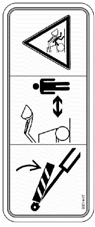


61 5. 4 DECAL CHART


62 5. 4 DECAL CHART On top of Radiator


 30 35 34. 39192 35. 44616 36.")
63 DECAL CHART T105 DECAL PARTS LIST (Kit)
Skid Steer Loader. Owner s and Operator s Manual. PUBLICATION NO July 2003
 175 Skid Steer Loader Owner s and Operator s Manual PUBLICATION NO. 48609 July 2003 THOMAS EQUIPMENT LIABILITY WARRANTY THE WARRANTY IS THE ONLY OBLIGATION OF THOMAS OR A THOMAS DEALER TO THE PURCHASER
T245 HDK. Skid Steer Loader. Owner s and Operator s Manual
 T245 HDK Skid Steer Loader Owner s and Operator s Manual PUBLICATION NO. 47640 August, 2001 THOMAS EQUIPMENT LIABILITY WARRANTY THE WARRANTY IS THE ONLY OBLIGATION OF THOMAS OR A THOMAS DEALER TO THE PURCHASER
Pro Tough Owner s and Operator s Manual
 Pro Tough 2200 Owner s and Operator s Manual PUBLICATION NO. 48241, MAY 2002 THOMAS EQUIPMENT LIABILITY WARRANTY THE WARRANTY IS THE ONLY OBLIGATION OF THOMAS OR A THOMAS DEALER TO THE PURCHASER OR ANYONE
35DT. Mini-Skid Loader
 35DT Mini-Skid Loader Owner s, Operator s and Parts Manual Publication Number - 52597 July, 2005 THOMAS EQUIPMENT LIABILITY WARRANTY THE WARRANTY IS THE ONLY OBLIGATION OF THOMAS OR A THOMAS DEALER TO
Walker Loader Bucket OPERATOR S AND PARTS MANUAL
 Walker Loader Bucket OPERATOR S AND PARTS MANUAL Please Read and Save These Instructions For Safety, Read all Safety and Operation Instructions Prior To Operating Machine P/N 6690 TABLE OF CONTENTS Introduction
OPERATORS MANUAL SAFETY & WARRANTY SECTION
 OPERATORS MANUAL SAFETY & WARRANTY SECTION KMW Ltd. 198 N. Hwy 281 Great Bend, Kansas 67530 800 445-7388 Fax 620 793-6737 ïïïkâãïäç~çéêëkåçã SAFETY FIRST This symbol, the industry s Safety Alert Symbol,
Trench Filler for Compact Utility Loaders
 Form No. 3353-608 Rev A Trench Filler for Compact Utility Loaders Model No. 22472 260000001 and Up Operator s Manual Register your product at www.toro.com Original Instructions (EN) Contents Page Introduction................................
Begin Program: Welcome everyone and introduce yourself, speaker(s) and/or interpreter if one is present/necessary. Feel free to include your name/prog
 and/or interpreter if one is present/necessary. Feel free to include your name/prog") Begin Program: Welcome everyone and introduce yourself, speaker(s) and/or interpreter if one is present/necessary. Feel free to include your name/program name on the title slide for purposes of personalization.
Begin Program: Welcome everyone and introduce yourself, speaker(s) and/or interpreter if one is present/necessary. Feel free to include your name/program name on the title slide for purposes of personalization.
Road Service Quick Reference Guide 2016 Lincoln MKZ / MKZ Hybrid. Quality and Education Services AAA Automotive 1000 AAA Drive Heathrow, FL 32746
 Road Service Quick Reference Guide 2016 Lincoln MKZ / MKZ Hybrid Quality and Education Services AAA Automotive 1000 AAA Drive Heathrow, FL 32746 December 12, 2015 Index Towing, Loading and Transporting
Mulcher Operators Manual
 Mulcher Operators Manual Skid Pro Attachments PO Box 982 Alexandria, MN 56308 October 2015 1 2 Contents 1. Introduction And Warranty... 4 1.1 Introduction... 4 1.2 Warranty... 4 2. Component Identification...
610 BUSHEL MANURE SPREADER
 610 BUSHEL MANURE SPREADER RODA MANUFACTURING 1008 LOCUST ST. HULL, IA. 51239 Art s-way Manufacturing 712-439-2366 Co., Inc. Hwy 9 West - PO Box 288 WWW.RODAMFG.COM Armstrong, IA. 50514 U.S.A 2 INTRODUCTION
Boring Unit Sitework Systems Attachment
 FORM NO. 6 Boring Unit Sitework Systems Attachment Model No. 0 89000 & Up Operator s Manual English (CE) Contents Page Introduction................................. Safety......................................
Backhoe for Dingo Compact Utility Loaders
 Form No. 50-5 Backhoe for Dingo Compact Utility Loaders Model No. 60 000000 & Up Operator s Manual Original Instructions (EN/GB) Contents Page Introduction................................. Safety......................................
WARNING this attachments capacity changes depending on the Skid Steer Loader it is hooked up to. CAPACITY AT 24 LOAD CENTER
 SKID STEER FORKLIFT ATTACHMENT Any piece of equipment can be dangerous if not operated properly. YOU are responsible for the safe operation of this equipment. The operator must carefully read and follow
BUCKET SWEEPER OPERATORS & PARTS MANUAL 2852 & 3174 SERIES
 OM628 BUCKET SWEEPER OPERATORS & PARTS MANUAL 2852 & 3174 SERIES MODEL 12002-5 FOOT WIDE X 24 INCH DIAMETER (SKID-STEER) MODEL 12004-6 FOOT WIDE X 24 INCH DIAMETER (SKID-STEER) MODEL 12017-6 FOOT WIDE
before serial number 2214
 before serial number 2214 Contents Page Safety Rules... 3 Pre-operational & Safety Inspection... 4 Operating Instructions... 6 Transport... 12 Maintenance & Routine Service... 12 Specifications... 14 SAFETY
R T SERIES ROTARY TILLER
 R T SERIES ROTARY TILLER Operating and Maintenance Manual TABLE OF CONTENTS 1. PRODUCT WARRANTY. 3 2. CHECKLIST Dealer s File Copy. 4 Customer s File Copy.. 5 3. INTRODUCTION 6 4. SPECIFICATIONS.. 7 5.
Mini Skid Steer Training
 Safe Operating Practices Mini Skid Steer Training This product is capable of amputating hands and feet. Always follow all safety instructions to avoid serious injury or death. Engine exhaust contains carbon
Prime Attachments & Custom Fab Brush Mower Owners/Operators Manual
 Prime Attachments & Custom Fab Brush Mower Owners/Operators Manual The operator is responsible for the safe operation and maintenance of the machine. It is important that anyone who uses the machine is
Talet Equipment International Ltd. Sand Kicker
 Talet Equipment International Ltd. Sand Kicker Parts & Operators Manual P.O. Box 35 Strathmore AB Canada TP K3 www.taletattachments.com sales@taletattachments.com Toll Free -888-37-5878 Fax -403-934-304
Backhoe for Compact Utility Loaders
 Form No. 54-4 Rev A Backhoe for Compact Utility Loaders Model No. 6 6000000 and Up Operator s Manual Register your product at www.toro.com. Original Instructions (EN) Contents Page Introduction.................................
John Deere. MODEL: 350C Crawler Loader, Bulldozer JD-O-OMT79469
 John Deere MODEL: 350C Crawler Loader, Bulldozer THIS IS A MANUAL PRODUCED BY JENSALES INC. WITHOUT THE AUTHORIZATION OF JOHN DEERE OR IT'S SUCCESSORS. JOHN DEERE AND IT'S SUCCESSORS ARE NOT RESPONSIBLE
Operator Manual. The most important component is you. This operator manual. has information for. all models of series. B plus some options and
 Operator Manual This operator manual has information for all models of series B plus some options and accessories. Some of the illustrations and information may not apply to your truck. The most important
1500 Series Roll Off Hoist. Owner s Manual (5-06)
") 1500 Series Roll Off Hoist Owner s Manual (5-06) Section 1: General Information Introduction Safety Information Warranty Information Table of Contents Section 2: Operation Operating the P.T.O. Operating
1500 Series Roll Off Hoist Owner s Manual (5-06) Section 1: General Information Introduction Safety Information Warranty Information Table of Contents Section 2: Operation Operating the P.T.O. Operating
TABLE OF CONTENTS. Warranty Disclaimers Delivery Checklist After Sale Checklist Safety Set Up... 8
 TABLE OF CONTENTS Pickett Equipment Warranty... 2 Warranty Disclaimers... 3 Delivery Checklist... 4 After Sale Checklist... 4 Safety... 5-7 Set Up... 8 Machine Adjustments and Operation... 9 Maintenance
Road Service Quick Reference Guide 2016 Lincoln MKX. Quality and Education Services AAA Automotive 1000 AAA Drive Heathrow, FL 32746
 Road Service Quick Reference Guide 2016 Lincoln MKX Quality and Education Services AAA Automotive 1000 AAA Drive Heathrow, FL 32746 December 12, 2015 Index Towing, Loading and Transporting 2 Curb Weight
OPERATOR S AND PARTS MANUAL PALLET FORKS. Part Number: MODEL NUMBER: Rev. 4
 OPERATOR S AND PARTS MANUAL PALLET FORKS SERIAL NUMBER: Manual Number: OM642 Part Number: 75542 MODEL NUMBER: Rev. 4 800-456-7100 I www.paladinlcg.com 503 Gay Street, Delhi, IA 52223, United States of
SAFETY AND OPERATION REQUIREMENTS CHART
 OPERATION, MAINTENANCE and SAFETY MANUAL MB16 and MTB16 Scoot-Crete Power Buggies IMPORTANT MACHINE SERVICE NOTES This manual covers the safety, operation and adjustment procedures for the Miller Scoot-Crete
RED23305 Owner s Manual
 RED23305 Owner s Manual 5 foot, 3-Point Mounted Snow Blower 270 West Park Avenue Huron, SD 57350 866-526-5682 Serial Number: Date of Purchase: Red Devil Snow Blower See Figure 1. 1. The Red Devil Snow
ROTARY BRUSH CUTTERS THE LEADER OF THE PACK OWNER/OPERATOR SAFETY & INSTRUCTION MANUAL
 72 M-AX ROTARY BRUSH CUTTERS THE LEADER OF THE PACK OWNER/OPERATOR SAFETY & INSTRUCTION MANUAL CONTENTS Page 1. Introduction..................................2 2. Safety Instructions...........................3-4
9-2 In case of emergency
 In case of emergency If you park your vehicle in case of an emergency... 9-2 Temporary spare tire... 9-2 Maintenance tools... 9-3 Flat tires... 9-5 Changing a flat tire... 9-5 Tire pressure monitoring
Wheel Horse. 44 Snowthrower. for 5xi Lawn and Garden Tractors. Model No & Up. Operator s Manual
 FORM NO. 8 Rev A Wheel Horse Snowthrower for 5xi Lawn and Garden Tractors Model No. 7966 890050 & Up Operator s Manual IMPORTANT: Read this manual, and your tractor manual, carefully. They contain information
36 Tiller Wheel Horse Lawn and Garden Tractor Attachment
 Form No. 9 6 Rev B 6 Tiller Wheel Horse Lawn and Garden Tractor Attachment Model No. 797 890000 and Up Operator s Manual English(En) Contents Page Introduction................................ Safety.....................................
1250 LB. CAPACITY MECHANICAL WHEEL DOLLY
 1250 LB. CAPACITY MECHANICAL WHEEL DOLLY 67287 SET-UP AND OPERATING INSTRUCTIONS Visit our website at: http://www.harborfreight.com Read this material before using this product. Failure to do so can result
Operator s Manual. Nitro 1000 Nitro 1000X. Nitro 750 Nitro 750X. September REV0
 Operator s Manual Nitro 750 Nitro 750X Nitro 1000 Nitro 1000X September.27.2018REV0 Table of Contents Introduction...3 Safety.....4 Equipment Requirements......5 What You Have Received. 5 Serial Number...6
Backhoe. Operation and Maintenance Manual
 Backhoe Operation and Maintenance Manual Revision Date: January 2018 Skid Pro Attachments PO Box 982 Alexandria, MN 56308 Toll Free: 877-378-4642 www.skidpro.com Contents INTRODUCTION... 2 To the Purchaser...
Road Service Quick Reference Guide 2016 Lincoln MKT. Quality and Education Services AAA Automotive 1000 AAA Drive Heathrow, FL 32746
 Road Service Quick Reference Guide 2016 Lincoln MKT Quality and Education Services AAA Automotive 1000 AAA Drive Heathrow, FL 32746 December 12, 2015 Index Towing, Loading and Transporting 2 Curb Weight
EZ Hauler 2500 Training & Procedure Manual
 EZ Hauler 2500 Training & Procedure Manual Load Capacity One of the most important considerations when operating this machine is the Load Capacity of the EZ Hauler 2500 s boom. The maximum weight capacity
Operator's Manual. VC-60 & VC-60 Plus Harper Industries, Inc. 7/03 Part No
 Operator's Manual VC-60 & VC-60 Plus 2003 Harper Industries, Inc. 7/03 Part No. 970066 Thank you for purchasing a Harper/Goossen Verti-Cutter. As with all Harper/Goossen products, the Harper/Goossen Verti-Cutter
Table of Contents. Technical Information Warning Statement
 Table of Contents Technical Information-----------------------------------1 Warning Statement--------------------------------------2 Read Before Riding-------------------------------------3 List of Parts-----------------------------------------------4
Operator s Manual. Operator s Manual BC-O-742
 Bobcat Operator s Manual 742 Operator s Manual THIS IS A MANUAL PRODUCED BY JENSALES INC. WITHOUT THE AUTHORIZATION OF BOBCAT OR IT S SUCCESSORS. BOBCAT AND IT S SUCCESSORS ARE NOT RESPONSIBLE FOR THE
MODEL HD99 HYDRAULIC ONE MAN TOWABLE EARTHDRILL
 DO NOT THROW AWAY IMPORTANT MANUAL MODEL HD99 HYDRAULIC ONE MAN TOWABLE EARTHDRILL Operators Manual GROUND HOG, INC. P.O.BOX 290 San Bernardino, CA. 92402 Phone (909) 478-5700 Fax (909) 478-5710 E-mail:
Road Service Quick Reference Guide 2016 Lincoln MKS. Quality and Education Services AAA Automotive 1000 AAA Drive Heathrow, FL 32746
 Road Service Quick Reference Guide 2016 Lincoln MKS Quality and Education Services AAA Automotive 1000 AAA Drive Heathrow, FL 32746 December 12, 2015 Index Towing, Loading and Transporting 2 Curb Weight
MT55 Mini Tracked Loader A3WU A3WU /02/2010
 Copyright 2000-2010 Bobcat Europe MT55 Mini Tracked Loader A3WU 11001 A3WU 99999 15/02/2010 Dimensions (A) Angle of departure 23.3 Carry position 168 mm (C) Dump angle at maximum height 49.6 (D) Dump height
HydroTote Trailer Hydroject Aerator
 Form No. 3355 89 Rev. C HydroTote Trailer Hydroject Aerator Model No. 09833 Serial No. 6000000 and Up Operator s Manual English (EN, GB) Contents Page Introduction................................. Safety......................................
W & A 12 ROW TOP LEVELING STACKER LEVEL BANDER
 W & A 12 ROW TOP LEVELING STACKER LEVEL BANDER NO. 3640 OPERATOR S MANUAL TO THE OWNER: Congratulations on your purchase of a new W & A Top Leveling Stacker Level Bander. Your selection is an indication
RedGum GP160 Splitter. Owner s Manual
 RedGum GP160 Splitter Owner s Manual Product Description & Intended Purpose: This Log Splitter / Wood Splitter is an outdoor product that splits wood logs for use as fuel in a fireplace or a woodstove.
Towing and Road Service Guide For Lexus LS 600h L. Quality and Education Services AAA Automotive 1000 AAA Drive Heathrow, FL 32746
 Towing and Road Service Guide For Lexus LS 600h L Quality and Education Services AAA Automotive 1000 AAA Drive Heathrow, FL 32746 June 15, 2007 Index General Towing Information Special Precautions 3 Hybrid
SHEYENNE TELE-BOOM OWNERS MANUAL OPERATOR INSTRUCTIONS PARTS BOOK
 SHEYENNE TELE-BOOM OWNERS MANUAL OPERATOR INSTRUCTIONS PARTS BOOK 701 Lenham Ave. SW PO Box 647 Cooperstown ND 58425 1-800-797-1883 701-797-2700 * 701-797-2584 Fax www.sheyennemfg.com TABLE OF CONTENTS
Road Service Quick Reference Guide 2016 Lincoln Navigator. Quality and Education Services AAA Automotive 1000 AAA Drive Heathrow, FL 32746
 Road Service Quick Reference Guide 2016 Lincoln Navigator Quality and Education Services AAA Automotive 1000 AAA Drive Heathrow, FL 32746 December 12, 2015 Index Towing, Loading and Transporting 2 Curb
Light condition and operation Windshield glass condition Wiper blade condition Paint condition and corrosion Fluid leaks Door and hood lock condition
 GENERAL CHECKS Engine Compartment The following should be checked regularly: Engine oil level and condition Transmission fluid level and condition Brake fluid level Clutch fluid level Engine coolant level
John Deere. MODEL: 410 Backhoe Loader JD-O-OMT66840
 John Deere MODEL: 410 Backhoe Loader THIS IS A MANUAL PRODUCED BY JENSALES INC. WITHOUT THE AUTHORIZATION OF JOHN DEERE OR IT'S SUCCESSORS. JOHN DEERE AND IT'S SUCCESSORS ARE NOT RESPONSIBLE FOR THE QUALITY
SECTION 1 7 OPERATION OF INSTRUMENTS AND CONTROLS Ignition switch, Transmission and Parking brake
 SECTION 1 7 OPERATION OF INSTRUMENTS AND CONTROLS Ignition switch, Transmission and Parking brake Ignition switch.............................................. 114 Automatic transmission.....................................
Wheel Horse. 36 Tiller. Model No & Up. Operator s Manual
 FORM NO. 8 9 Rev. A Wheel Horse 6 Tiller for Classic Garden Tractors Model No. 7970 690000 & Up Operator s Manual IMPORTANT: Read this manual carefully. It contains information about your safety and the
Table of Contents. Safety symbols... 3 Assembly 6. Operation Maintenance Troubleshooting 11. Storage. 12. Notes. 13
 Table of Contents Safety symbols... 3 Assembly 6 Operation... 8 Maintenance... 10 Troubleshooting 11 Storage. 12 Notes. 13 2 Safety Information Attention; this machine can be dangerous! All operators should
Multi-Purpose Tool Sitework Systems Attachment
 FORM NO. 22 648 Multi-Purpose Tool Sitework Systems Attachment Model No. 2242 89000 & Up Operator s Manual English (CE) Contents Page Introduction................................. 2 Safety......................................
Miller Compact Manual Quick Couplers
 Miller: Issue 2 Miller Compact Manual Quick Couplers For Mini Excavators (1 to 10 tonne) and Backhoe Loaders Installation Guide and Operator s Instructions IMPORTANT Keep this manual with the machine at
Section 4.3. Machine Operation - Operating Procedures. Before Starting the Engine: General Pre-Start Inspection
 Section 4.3 Machine Operation - Operating Procedures Before Starting the Engine: General Pre-Start Inspection... 4.3.2 Engine Starting Procedure... 4.3.2 Cold Weather Start-Up... 4.3.3 Engine Shutdown
Operating and Assembly Manual
 Model 1080 Operating and Assembly Manual Midwest Equipment Manufacturing, Inc. 5225 Serum Plant Road Thorntown, IN 46071 08-02-16 SAFETY RULES Remember, any power equipment can cause injury if operated
Talet Equipment International Ltd. Sanding Auger Bucket
 Talet Equipment International Ltd. Sanding Auger Bucket Parts & Operators Manual P.O. Box 35 Strathmore AB Canada TP K3 www.taletattachments.com sales@taletattachments.com Toll Free -888-37-5878 Fax -403-934-304
Extreme Duty Grapple (Rock, Skeleton, Scrap & Tine) Operation and Maintenance Manual
 Operation and Maintenance Manual") Extreme Duty Grapple (Rock, Skeleton, Scrap & Tine) Operation and Maintenance Manual Revision Date: May 12, 2017 Skid Pro PO Box 982 Alexandria, MN 56308 Toll Free: 877-378-4642 www.skidpro.com TABLE OF
Extreme Duty Grapple (Rock, Skeleton, Scrap & Tine) Operation and Maintenance Manual Revision Date: May 12, 2017 Skid Pro PO Box 982 Alexandria, MN 56308 Toll Free: 877-378-4642 www.skidpro.com TABLE OF
Trencher Dingo Attachment
 Form No. 3326-453 Trencher Dingo Attachment Model No. 22459 2000000 & Up Operator s Manual English (CE) Contents Page Introduction................................ 2 Safety.....................................
Towing and Road Service Guide For The 2010 Lexus HS250H. Quality and Education Services AAA Automotive 1000 AAA Drive Heathrow, FL 32746
 Towing and Road Service Guide For The 2010 Lexus HS250H Quality and Education Services AAA Automotive 1000 AAA Drive Heathrow, FL 32746 October 7, 2009 Index General Vehicle Information Major Component
North Dakota State University Grounds Maintenance Equipment
 North Dakota State University Grounds Maintenance Equipment I. Introduction Grounds maintenance equipment is an important part of the work activities on NDSU campus. They can make grounds maintenance jobs
OWNER S, INSTALLATION AND PARTS MANUAL
 OWNER S, INSTALLATION AND PARTS MANUAL QUICK HITCH CONVERSION KIT CONVERTS 24/MT TO 26 SERIES HITCH FOR PLOW SERIAL NUMBERS AFTER 24G100000 24D100000 MTD200000 MTG200000 2005 Sno-Way International 97101198A
TOWABLE EXCAVATOR USER MANUAL. Please read and understand all instructions before use. Retain this manual for future reference.
 TOWABLE EXCAVATOR USER MANUAL Please read and understand all instructions before use. Retain this manual for future reference. 10005833-10 REV2 TABLE OF CONTENTS Introduction 2 Functions 2 Specifications
POST HOLE DIGGER. Operation, Service & Parts Manual For Models D20 & D40. FORM: D20_40DigRev.QXD
 POST HOLE DIGGER Operation, Service & Parts Manual For Models D20 & D40 FORM: D20_40DigRev.QXD September 2006 Revised August 2009 TABLE OF CONTENTS Introduction.............................1 Preparation..............................2
Towing and Road Service Guide For The Lexus ES300h. Quality and Education Services AAA Automotive 1000 AAA Drive Heathrow, FL 32746
 Towing and Road Service Guide For The Lexus ES300h Quality and Education Services AAA Automotive 1000 AAA Drive Heathrow, FL 32746 September 7, 2012 1 Index General Vehicle Information Major Component
Road Service Quick Reference Guide 2016 Lincoln MKC. Quality and Education Services AAA Automotive 1000 AAA Drive Heathrow, FL 32746
 Road Service Quick Reference Guide 2016 Lincoln MKC Quality and Education Services AAA Automotive 1000 AAA Drive Heathrow, FL 32746 December 12, 2015 Index Towing, Loading and Transporting 2 Curb Weight
Richmond Conveyor. Hydraulic Ultimate Manual. January 2013
 Richmond Conveyor Hydraulic Ultimate Manual January 2013 Table of Contents Operators Manual Removing conveyor from truck Maintenance checklist Maintenance kit material list Safety information Index Installation
Owner s Manual. Instructions for Assembly, Testing, Operation, and Servicing. Trailer Kit: High speed upgrade kit used with Item# WARNING
 M268176D.1 ITEM NUMBER: 268176 SERIAL NUMBER: Owner s Manual Instructions for Assembly, Testing, Operation, and Servicing Trailer Kit: High speed upgrade kit used with Item# 268175 WARNING READ and UNDERSTAND
Service Manual S160 Skid-Steer Loader
 Service Manual S160 Skid-Steer Loader S/N 529960001 & Above S/N 530060001 & Above S/N AC3260001 & Above S/N AHWA11001 & Above EQUIPPED WITH BOBCAT INTERLOCK CONTROL SYSTEM (BICS ) 6987034 (9-09) Printed
REPAIR MANUAL Publication No April, 2005 THOMAS
 REPAIR MANUAL 250 255 Publication No. 49903 April, 2005 THOMAS THOMAS EQUIPMENT LIABILITY WARRANTY THE WARRANTY IS THE ONLY OBLIGATION OF THOMAS OR A THOMAS DEALER TO THE PURCHASER OR ANYONE ELSE CONCERNING
LARGE FRAME SKID-STEER LOADERS S220 S250 S300 S330
 LARGE FRAME SKID-STEER LOADERS S220 S250 S300 S330 Large Frame Skid-Steer Loaders Bobcat Large Frame Skid-Steer Loaders Name your task Bobcat large frame skid-steer loaders cut em down to size. These rugged
Wind and Temperature Tip Over Hazard Do not add notice boards or similar
 Lift & Work Platform Safety Information Safety Information: Boom Lifts Safety Information: Scissor Lifts Safety Information: Boom Lifts Power Lines Electrocution Hazard Maintain safe clearance from Electrical
Operator Manual. This operator manual has. information for all models. of series M plus some. options and accessories. Some of the illustrations
 M S E R I E Operator Manual S This operator manual has information for all models of series M plus some options and accessories. Some of the illustrations and information may not The most apply to your
1.CONTENTS 1. Contents Control location Before riding Safe riding Driving Use genuine spare parts Use
 1.CONTENTS 1. Contents... 1 2. Control location... 3 3. Before riding... 4 4. Safe riding... 4 5. Driving... 5 6. Use genuine spare parts... 5 7. Use of each component... 6 Gauges... 6 Operation of ignition
Rotary Brush Cutter. Model Number RBV. Serial Number. Serial Number and Greater. Maximum Flow Rate gpm. Phone: RBV
 Rotary Brush Cutter Model Number RBV. Serial Number. Serial Number 75 and Greater Maximum Flow Rate gpm. Phone: 0--700 0/5/0 Revised // RBV Features of Virnig Mfg. Inc. Rotary Brush Cutter include: diameter
MK AUGERS POWER SWING KIT ASSEMBLY & OPERATION MANUAL
 MK AUGERS POWER SWING KIT ASSEMBLY & OPERATION MANUAL Read this manual before using product. Failure to follow instructions and safety precautions can result in serious injury, death, or property damage.
ROTARY TILLER. Operation, Service & Parts Manual For "AS" Series. FORM: ASTillerBook.QXD
 ROTARY TILLER Operation, Service & Parts Manual For "AS" Series FORM: ASTillerBook.QXD April 2002 TABLE OF CONTENTS Preparation......................................1 Assembly Instructions.............................2
S600/S600TX. There s nothing mini about their productivity
 Mini Skid Steers Mini Skid Steers S600/S600TX There s nothing mini about their productivity From landscape contractors to do-it-yourselfers, the Vermeer mini skid steer is a machine built for multiple
Towing and Road Service Guide For Lexus GS 300 and GS 430. Quality and Education Services AAA Automotive 1000 AAA Drive Heathrow, FL 32746
 Towing and Road Service Guide For Lexus GS 300 and GS 430 Quality and Education Services AAA Automotive 1000 AAA Drive Heathrow, FL 32746 April 12, 2005 Index Equipment availability 3 General Towing Information
MODEL 1824TK TK HYDRAULIC TRACK TRENCHER OPERATOR S MANUAL
 THE MODEL 1824TK - 2324TK HYDRAULIC TRACK TRENCHER OPERATOR S MANUAL TRENCHER INTENDED USE This machine is designed for digging trenches in normal ground of reasonably soft dirt and stones up to 6 (15cm)
INSTALLATION GUIDE. Universal System for Zero Turn Mowers
 INSTALLATION GUIDE Universal System for Zero Turn Mowers Table of Contents General Information 1 Important Notice to Purchaser 2 Specifications 2 Intended Usage 2 Important Information 3 General Safety
New Bremen, Ohio USA 2004 PF14387-WEB Rev. 6/06 Printed in U.S.A.
 New Bremen, Ohio 45869 USA 2004 PF14387-WEB Rev. 6/06 Printed in U.S.A. You Must be Trained It s the law, you must be trained and certified to operate this truck. (OSHA 1910.178, Rev. 1999) You or others
ATD Amp Carbon Pile Battery Tester User s Manual WARNING
 ATD-5489 500 Amp Carbon Pile Battery Tester User s Manual WARNING Failur e to follow instructions may cause damage or explosion, always shield eyes. Read entire instruction manual before use. Warning:
Owner s Manual: PS4000 4,000 LB. WINCH
 Owner s Manual: PS4000 4,000 LB. WINCH PIERCE ARROW INC. 549 U.S. HWY 287 S. HENRIETTA, TEXAS 76365 ---------------------------------------------------- TOLL FREE 800-658-6301 FAX 940-538-4382 ----------------------------------------------------
OPERATOR S MANUAL 7(5 & ( 8&. $5.00 P/N REV.B
 OPERATOR S MANUAL &281 2817( 7(5 %$/$1&( /,)7 7758& 8&. $5.00 P/N 901345 REV.B As a lift truck operator, you are responsible for a machine that is useful, powerful, and can be hazardous if not operated
Instruction Manual for Operation & Maintenance
 Instruction Manual for Operation & Maintenance BigSprinkler.com 15250 Sunshine Rd. Yukon, OK. 73099 1-855-805-7901 Introduction Thank you for purchasing a ReelGreen RG25 Traveling Sprinkler System. Please
Rotary Brush Cutter (Standard Flow)
") Rotary Brush Cutter (Standard Flow) Model Number RBV. Serial Number. Serial Number 6795-0050 Maximum Flow Rate gpm. For and 5 GPM Max Models Phone: 0-9-700 0/5/0 Revised // RBV Features of Virnig Mfg.
Rotary Brush Cutter (Standard Flow) Model Number RBV. Serial Number. Serial Number 6795-0050 Maximum Flow Rate gpm. For and 5 GPM Max Models Phone: 0-9-700 0/5/0 Revised // RBV Features of Virnig Mfg.
MODEL 20RTK-23RTK STAND ON HYDRAULIC TRACK TRENCHER OPERATOR S MANUAL
 THE MODEL 20RTK-23RTK STAND ON HYDRAULIC TRACK TRENCHER OPERATOR S MANUAL TRENCHER INTENDED USE This machine is designed for digging trenches in normal ground of reasonably soft dirt and stones up to 6
Operators and Safety Manual. Model 8042/ S/N 9908 & Before OCTOBER 1999 ANSI
 Operators and Safety Manual Model 8042/10042 S/N 9908 & Before 8990186-006 OCTOBER 1999 ANSI WARNING IMPROPER OPERATION OF THIS VEHICLE CAN CAUSE INJURY OR DEATH. BEFORE STARTING THE ENGINE, DO THE FOLLOWING:
440 & 443 Skid Steer
 Bobcat 440 & 443 Skid Steer THIS IS A MANUAL PRODUCED BY JENSALES INC. WITHOUT THE AUTHORIZATION OF BOBCAT OR IT S SUCCESSORS. BOBCAT AND IT S SUCCESSORS ARE NOT RESPONSIBLE FOR THE QUALITY OR ACCURACY
WARNING - BEFORE YOU DRIVE
 See back cover for a pre-ride checklist section 3 operation WARNING - BEFORE YOU DRIVE 1. Always perform a pre-ride inspection of the vehicle using the checklist provided on the back cover of this manual.
EAVERLINE. Operator s Manual. Series 5 Feed Cart Models 521, 525, 531 & 537. Weaverline, LLC - Churchtown, PA 17555
 EAVERLINE Operator s Manual Series 5 Feed Cart Models 521, 525, 531 & 537 CAUTION: Drive at a speed slow enough to ensure safety and complete control at all times. CAUTION: Know the controls and how to
Operating and Assembly Manual
 Model 455-IC/PRO/H Operating and Assembly Manual Midwest Equipment Manufacturing, Inc. 5225 Serum Plant Road Thorntown, IN 46071 03-08-12 SAFETY RULES Remember, any power equipment can cause injury if
Road Service Quick Reference Guide Jaguar XF. Quality and Education Services AAA Automotive 1000 AAA Drive Heathrow, FL 32746
 Road Service Quick Reference Guide 2016-2017 Jaguar XF Quality and Education Services AAA Automotive 1000 AAA Drive Heathrow, FL 32746 March 31, 2017 Index Quick Specifications and Information 2 Start/Stop
Operator s Manual. Power V Plow Toro 7200/7210
 Operator s Manual Power V Plow Toro 7200/7210 M-B Companies, Inc.: 1615 Wisconsin Avenue, P.O. Box 200 New Holstein, WI 53061 Telephone: 800-558-5800 FAX: (920) 898-4588 CONTENTS: Table of Contents Safety...
Model 452-DIC/DH. Operating and Assembly Manual
 . Model 452-DIC/DH Operating and Assembly Manual Palmor Products Inc. 5225 Serum Plant Road Thorntown, IN 46071 02-14-12 SAFETY RULES Remember, any power equipment can cause injury if operated improperly
CAUTION. Start & Stop Procedures. Section 1-2. Engine Oil Level
 Section 1-2 Start & Stop Procedures Before operating this machine, the operator must have: received operator training, a familiarity with this manual, and a complete understanding of all the procedures