Control Units Ex e Glass Fiber Reinforced Polyester
|
|
|
- Hope Wood
- 5 years ago
- Views:
Transcription


1 Features Assembly Glass fiber reinforced polyester (GRP) enclosures Suitable for operation in Zones 1, 2, 21 and 22 Certified Ex de, Ex ib and Ex tb Up to 4 operators per control unit, base-mounted contact blocks Wide choice of operators, including o Pushbuttons o Illuminated pushbuttons o Emergency stop buttons with various labeling and release options o LED indicators o LED indicators for Ex i circuits o Control switches in various variants o Key-operated switches o Potentiometers o Ammeters/Voltmeters o uzzers and flashing buzzers Customizable configuration of operators and cable gland types as per specification Wide range of labels and accessories available Function The versatile control units of the LCP series are available as standard off-the-shelf control units or can be flexibly equipped with a great variety of operators, labels, cable glands and accessories. The comprehensive range of control functions allow the configuration of each control unit to exactly meet any application requirements and ensure optimal space efficiency. The enclosures are manufactured from glass fiber reinforced polyester. Durable materials and components of high quality allow the control units to be used in harsh ambient conditions. Configuration Examples 1
2 Technical Data Electrical specifications Operating voltage 250 V AC max., depending on terminals and equipment fitted Operating current 16 A max., depending on terminals and equipment fitted Mechanical Specification Dimensions see dimensions data table Enclosure cover fully detachable Cover fixing M6 stainless steel socket cap hex head screws Tightening torque 2 Nm Protection degree IP66 Cable entry cable glands as per specification, see also individual datasheets Cable entry areas faces [A] and [] Terminal capacity 2.5 mm 2 Material Enclosure carbon loaded, antistatic glass fiber reinforced polyester (GRP) Finish inherent colour black Gasket silicone cord Mass see dimensions data table Grounding 2.5 mm 2 grounding terminal Ambient Conditions Ambient temperature C, optional -50 C Data for application in connection with Ex-areas EC-Type Examination Certificate CML 16ATEX3009X Marking II 2 GD Ex db eb mb IIC T* Gb Ex ib IIC T* Gb Ex db eb ib mb IIC T* Gb Ex tb IIIC T** C Db T6/T80 Ta +40 C T4/T130 Ta +55 C International approvals IECEx approval IECEx CML X EAC approval TC RU C-DE.G CCOE approval A/P/HQ/MH/104/3144(P325155) Conformity Protection degree EN General information Supplementary information EC-Type Examination Certificate, Statement of Conformity, Declaration of Conformity, Attestation of Conformity and instructions have to be observed where applicable. For information see Accessories Optional accessories see enclosure accessories table 2
3 Standard Control Units Type Functions Contact configuration D (1) Labeling LCP1.PGMX.* Pushbutton, green I LCP1.PRMX.* Pushbutton, red 0 LCP1.ERMX.* Emergency stop mushroom button, red Emergency Stop / Not Halt LCP1.ERMZA.* LCP1.ERMZP.* Emergency stop mushroom button, red, with protective shroud, plastic Emergency stop mushroom button, red, with protective shroud, plastic, padlockable LCP1.IGIX.* Illuminated pushbutton, green 1x NO LCP1.IRJX.* Illuminated pushbutton, red 1x NC LCP1.JRMX.* Key-release emergency mushroom button, red LCP1.DMMX.* Double pushbutton, red/green 0 - I LCP1.N1OX.* Small control switch, 2 position with left OFF 2x NO I LCP1.N2MX.* Small control switch, 2 position 2 I - II LCP1.N3OX.* Small control switch, 3 position with center OFF 2x NO 4 I II LCP1.S1OX.* Large control switch, 2 position with left OFF 2x NO I LCP1.S2MX.* Large control switch, 2 position 2 I - II LCP1.S3OX.* Large control switch, 3 position with center OFF 2x NO 4 I II LCP1.K1OX.* Key switch, 2 position with left OFF 2x NO I LCP1.K3OX.* Key switch, 3 position with center OFF 2x NO 4 I II LCP1.LGLX.* LCP1.LRLX.* LED indicator, green LED indicator, red Emergency Stop / Not Halt Emergency Stop / Not Halt LCP7.WAASA.* Ammeter 1A Scale A LCP2.PGMX.PRMX.* LCP2.PGMX.ERMX.* LCP2.PGMX.JRMX.* Pushbutton, green Pushbutton, red Pushbutton, green Emergency stop mushroom button, red Pushbutton, green Key-release emergency mushroom button, red I 0 I Emergency Stop / Not Halt I (1) see switching diagrams of operating elements in tables overleaf * Configuration of cable entries see overleaf Table continues overleaf. 3
4 Standard Control Units continued Type Functions Contact configuration D (1) Labeling LCP8.WAASA.N5MX.* Ammeter 1A Small control switch, 3 position with left OFF 3 Scale A 0 - I - II LCP3.PGMX.PRMX.ERMX.* Pushbutton, green Pushbutton, red Emergency stop mushroom button, red I 0 Emergency Stop / Not Halt LCP3.LGLX.PGMX.PRMX.* LED indicator, green Pushbutton, green Pushbutton, red I 0 LCP3.LRLX.PGMX.PRMX.* LED indicator, red Pushbutton, green Pushbutton, red I 0 LCP3.LRLX.LYLX.LGLX.* LED indicator, red LED indicator, yellow LED indicator, green LCP3.LRLX.DMMX.JRMX.* LED indicator, red Double pushbutton, red/green Key-release emergency mushroom button, red 0 - I LCP9.WAASA.PGMX.PRMX.* Ammeter 1A Pushbutton, green Pushbutton, red Scale A I 0 LCP4.LRLX.PGMX.PRMX.ERMX.* LED indicator, red Pushbutton, green Pushbutton, red Emergency stop mushroom button, red I 0 Emergency Stop / Not Halt (1) see switching diagrams of operating elements in tables overleaf * Configuration of cable entries see overleaf For further configurations please contact Pepperl+Fuchs. 4
5 Dimensions Legend A - Maximum external dimension, vertical - Maximum external dimension, horizontal C - Maximum external dimension, depth C1 - Maximum external dimension, depth with operator G - Mounting holes center, vertical H - Mounting holes center, horizontal J - Mounting holes diameter K - Maximum external dimension with mounting brackets [A] - Entry face [] - Entry face For details see dimensions data tables Dimensions and max. Functions Enclosure Type Qty. (1) Dimensions [mm] (2) Mounting [mm] Mass (3) A C C1 K G H J [kg] LCP1.* 1x S / 1x L LCP2.* 2x S LCP2.4P.* 1x S / 1x L (4) LCP3.* 3x S / 3x L LCP4.* 4x S LCP7.* 1x A LCP8.* 1x A, 1x S LCP9.* 1x A, 2x S (1) = Max. quantity of functions, see configuration table overleaf Actuator heads: S = small, L = large, A = Ammeter/Voltmeter (2) = Dimension C1 is maximum, it will differ according to operating elements configuration (3) = Empty enclosure, weight will increase according to operating elements and installations (4) = Used with 4 pole contact modules Optional Enclosure Accessories Engraved traffolyte tag label Engraved AISI 316L stainless steel tag label Color in-fill AISI316L stainless steel tag label 5
6 Configurations with 1 function - types of operating elements see overleaf LCP1.* LCP1.* LCP2.4P.* LCP7.* maximum configuration (1) large operator 2 pole (2) large operator 4 pole (3) window (4) Configurations with 2 functions - types of operating elements see overleaf LCP2.* LCP8.* maximum configuration (1) window + 1 small operator (4) Configurations with 3 functions - types of operating elements see overleaf LCP3.* LCP3.* LCP9.* maximum configuration (1) large operator 2 pole (2) window + 2 small operators (4) Configurations with 4 functions - types of operating elements see overleaf LCP4.* maximum configuration (1) (1) = Small operators with 2 pole contact blocks Small operators include all pushbuttons, small switching actuators, LED indicators and potentiometers (2) = Large switching actuators and all operators fitted with 2 pole contact modules, protective lid or padlockable shroud (3) = Small and large switching actuators and all operators fitted with 4 pole contact modules, protective lid or padlockable shroud (4) = Viewing windows with ammeter or voltmeter in combination with operators Note: the use of label holders depends on operator configuration For further configurations please contact Pepperl+Fuchs 6
7 Type code / model number Series LC Control Unit : Material : P GRP glass fiber reinforced polyester : : Enclosure type / quantity of operating elements : : through 4 operating elements, see dimensions data table : : 7 1 window for ammeter/voltmeter : : 8 1 window for ammeter/voltmeter and 1 operating element : : 9 1 window for ammeter/voltmeter and 2 operating elements : : : Function 1 : : : xxxxx see operating elements type codes : : : : Function 2 : : : : xxxxx see operating elements type codes : : : : : Function 3 : : : : : xxxxx see operating elements type codes : : : : : : Function 4 : : : : : : xxxxx see operating elements type codes : : : : : : : Entry configuration / cable glands : : : : : : : A... M standard entry configurations, see cable entries table : : : : : : : X no entries : : : : : : : Z customized entries : : : : : : : : Type of explosion protection : : : : : : : : no character indicates Ex e (former versions) : : : : : : : : 1 Ex db eb mb, Ex tb : : : : : : : : 3 Ex ib, Ex tb : : : : : : : : 5 Ex db eb ib mb, Ex tb LC P n.xxxx.xxxx.xxxx.xxxx.x.x LC P 2.N1OX.ERMZP.E.1 Example Example: Control Unit, GRP enclosure prepared for 2 functions. Upper function: small control switch 2 position with left OFF, labeled "0 - I", base-mounted contact block with 2x NO contacts, no accessories. Lower function: pull-to-release mushroom button, red, labeled "NOT HALT EMERGENCY STOP", base-mounted contact block with contacts, emergency stop shroud, plastic, padlockable. Cable entry configuration: top face one stopping plug M20 polyamide, bottom face one cable gland M20 for non-armored cables, polyamide. Type of protection: Ex db eb mb and Ex tb. Operating elements type code Actuator head xx pushbutton, rotary switching actuator, LED indicator, measuring instrument, and more - see separate tables : Contact element : x contact block, contact module or rotary switching block - see separate tables : : Operator accessory : : xx accessories for individual control functions - see separate table xx x xx ER M ZP Example Example: Mushroom button 40 mm, red, pull-to-release, labeled "NOT HALT EMERGENCY STOP", base-mounted contact block with contacts, emergency stop shroud, plastic, padlockable For configuration of operating elements see tables overleaf 7
8 Cable Entry Configurations Type code (1) A C D E F G H J K L M X Z Face (2) Description Entry qty. Entry devices type code (3) Clamping range [mm] A No entry 0 Cable gland M20 for non-armored cables, polyamide black, Ex e certified 1x M20 CG.PEDS.M20.PA.C A Stopping plug M20, polyamide black, Ex e certified 1x M20 SP.PE.M20.PA.C.11 Cable gland M20 for non-armored cables, polyamide black, Ex e certified 1x M20 CG.PEDS.M20.PA.C A No entry 0 Cable gland M20 for non-armored cables, Stopping plug M20, polyamide black, Ex e certified 2x M20 A No entry 0 Cable gland M20 for armored cables, brass nickelplated, Ex e certified A Stopping plug M20, brass nickel-plated, Ex e certified 1x M20 Cable gland M20 for armored cables, brass nickelplated, Ex e certified A No entry 0 Cable gland M25 for non-armored cables, polyamide black, Ex e certified CG.PEDS.M20.PA.C.15, SP.PE.M20.PA.C x M20 CG.AR.M20.N.C SP.MD.M20.N.C.15 1x M20 CG.AR.M20.N.C x M25 CG.PEDS.M25.PA.C A Stopping plug M25, polyamide black, Ex e certified 1x M25 SP.PE.M25.PA.C.15 Cable gland M20 for non-armored cables, Stopping 2x M20 CG.PEDS.M20.PA.C.15, plug M20, polyamide black, Ex e certified SP.PE.M20.PA.C A Stopping plug M20, brass nickel-plated, Ex e certified 1x M20 SP.MD.M20.N.C.15 Cable gland M20 for non-armored cables, brass nickel-plated, Ex e certified 1x M20 CG.NA.M20.N.C A Stopping plug M20, polyamide black, Ex e certified 1x M20 SP.PE.M20.PA.C.11 Stopping plug M20, polyamide black, Ex e certified 1x M20 SP.PE.M20.PA.C.11 A Stopping plug M25, polyamide black, Ex e certified 1x M25 SP.PE.M25.PA.C.15 Cable gland M25 for non-armored cables, polyamide black, Ex e certified 1x M25 CG.PEDS.M25.PA.C A No entry 0 reather drain M20, polyamide black, Ex e certified 1x M20 D* Cable gland M20 for non-armored cables, polyamide black, Ex e certified 1x M20 CG.PEDS.M20.PA.C A No entry 0 Stopping plugs M20, polyamide black, Ex e certified 2x M20 SP.PE.M20.PA.C.11 A No entry 0 No entry 0 A Customized entry configuration, please contact customer service Customized entry configuration, please contact customer service As per specification As per specification (1) = Digit in type code of control unit, see type code table (2) = Entry faces, A: enclosure top, : enclosure bottom (3) = For details see individual data sheets 8


")
9 Ex de Pushbuttons and Emergency Stops Pushbutton Actuators Heads Red pushbutton with blank insert Red pushbutton with insert labeled "O" Red pushbutton with insert labeled "STOP" Red pushbutton with insert labeled "OFF" Green pushbutton with blank insert Green pushbutton with insert labeled "I" Green pushbutton with insert labeled "START" Green pushbutton with insert labeled "ON" PH Green pushbutton (PG) Yellow pushbutton with blank insert Amber pushbutton with blank insert White pushbutton with blank insert lue pushbutton with blank insert lue pushbutton with insert labeled "RESET" lack pushbutton with blank insert lack pushbutton with insert labeled "0" lack pushbutton with insert labeled "I" lack pushbutton with insert labeled "II" lack pushbutton with insert labeled "III" lack pushbutton with insert labeled "IV" lack pushbutton with insert labeled " " lack pushbutton with insert labeled " " Pushbutton with unlabeled inserts colored amber, black, blue, green, red, white Emergency Stop Actuator Heads Mushroom button 40 mm, red, pull-to-release Mushroom button 40 mm, red, pull-to-release, labeled "NOT HALT EMERGENCY STOP" Mushroom button 40 mm, red, pull-to-release, labeled "NOT AUS EMERGENCY STOP Mushroom button 40 mm, red, twist-to-release Mushroom button 55 mm, red, twist-to-release Mushroom button 39 mm, red, key release PA PR PC PD PE PG PF PY PO PW P PJ PK PL PN PP PQ PT PU PV PZ1 MRL ER E6 E4 E5 JR Mushroom button pull-to-release (E6) Other Pushbutton Actuator Heads Double pushbutton red/green labeled "0 - I" DM Mushroom pushbutton 39 mm, black MK Mushroom pushbutton 39 mm, red MR Mushroom pushbutton 39 mm, green MG Mushroom button twist-to-release (E4) Mushroom pushbutton (MK) Mushroom button key release (JR) 9


10 Ex de Pushbuttons and Emergency Stops Contact locks, base-mounted Contact block with contacts M Contact block with 2x NC contacts C Contact block with 2x NO contacts O Contact block with 2x NO / 2x NC contacts 01 Contact block with 4x NC contacts 02 Contact block with 4x NO contacts 03 Contact block with 1x NO / 3x NC contacts 04 Contact block with 3x NO / 1x NC contacts 05 ase-mounted Contact lock Technical Data Contact locks Utilization category AC12 AC15 DC13 DC13 Rated operating voltage 250 V 250 V 110 V 24 V Rated operating current 16 A 10 A 1 A 1 A Terminals, max. core cross-section 2 x 2.5 mm 2 2 x 2.5 mm 2 2 x 2.5 mm 2 2 x 2.5 mm 2 Ex de Illuminated Pushbuttons Illuminated Pushbutton Actuator Heads Red illuminated pushbutton Green illuminated pushbutton Amber illuminated pushbutton White illuminated pushbutton lue illuminated pushbutton IR IG IO IW I lue Pushbutton Actuator (I) LED Contact Modules, base-mounted LED module V AC/DC with 1x NO contact LED module V AC/DC with 1x NC contact I J ase-mounted LED Module Technical Data LED Contact Modules Utilization category AC15 DC13 Rated operating voltage V V Rated operating current 10 A 1 A Terminals, max. core cross-section 2 x 2.5 mm 2 2 x 2.5 mm 2 Power consumption 1 W 1 W 10
 Action (3) Labeling Actuator (4) Small actuator, 2 position with left OFF O 2x NO 1 L - L 0 - I N1 Small actuator, 2 position M 2 L - L I - II N2 Small actuator, 3 position with center OFF O 2x")


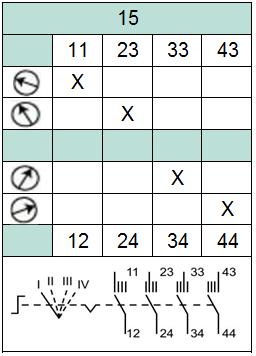
11 Ex de Control Switches, 2 Pole Contact locks Switching Actuator Heads for use with 2 Pole Contact locks lock (1) Contacts Diag. (2) Action (3) Labeling Actuator (4) Small actuator, 2 position with left OFF O 2x NO 1 L - L 0 - I N1 Small actuator, 2 position M 2 L - L I - II N2 Small actuator, 3 position with center OFF O 2x NO 4 L - L - L I II N3 Small actuator, 3 position with center OFF, spring return O 2x NO 4 S - L - S I II N3S Small actuator, 3 position with left OFF M 3 L - L - L 0 - I - II N5 Large actuator, 2 position with left OFF, padlockable in "0" O 2x NO 1 L - L 0 - I S1 Large actuator, 2 position M 2 L - L I - II S2 Large actuator, 3 position with center OFF, padlockable in "0" O 2x NO 4 L - L - L I II S3 Large actuator, 3 position with center OFF, spring return, padlockable in "0" O 2x NO 4 S - L - S I II S3S Large actuator, 3 position with left OFF M 3 L - L - L 0 - I - II S5 Key switch actuator, 2 position with left OFF O 2x NO 1 L - L 0 - I K1 Key switch actuator, 2 position with left OFF, spring return O 2x NO 1 L - S 0 - I K1S Key switch actuator, 3 position with center OFF O 2x NO 4 L - L - L I II K3 Key switch actuator, 3 position with center OFF, spring return O 2x NO 4 S - L - S I II K3S Note: all switching actuators are black, the large ones are shrouded (1) = Type code of 2 pole contact blocks, base-mounted (2) = Switching diagrams see below (3) = Action: L = latching, S = spring return (4) = Type code of switching actuator heads Contact locks 2 Pole, base-mounted Contact block with contacts Contact block with 2x NC contacts Contact block with 2x NO contacts Type Code M C O Switching Diagrams 2 Pole Contact locks Technical Data Contact locks Utilization category AC12 AC15 DC13 DC13 Rated operating voltage 250 V 250 V 110 V 24 V Rated operating current 16 A 10 A 1 A 1 A Terminals, max. core cross-section 2 x 2.5 mm 2 2 x 2.5 mm 2 2 x 2.5 mm 2 2 x 2.5 mm 2 11
")
 Action (3) Labeling Actuator (4) Large actuator, 2 position with left OFF, padlockable in \"0\" 03")

 = Type code of 4 pole contact blocks, base-mounted (2) = Switching diagrams see")


12 Small Actuator (N*) Key Switch Actuator (K*) Large Actuator with Shroud (T*, S*) Ex de Control Switches, 4 Pole Contact locks Switching Actuator Heads for use with 4 Pole Contact locks lock (1) Contacts Diag. (2) Action (3) Labeling Actuator (4) Large actuator, 2 position with left OFF, padlockable in "0" 03 4x NO 5 L - L 0 - I S1 Large actuator, 2 position 01 2x NO / 2x NC 6 L - L I - II S2 Large actuator, 3 position with center OFF, padlockable in "0" 03 4x NO 7 L - L - L I II S3 Large actuator, 3 position with center OFF, spring return, padlockable in "0" Note: all switching actuators are black and shrouded (1) = Type code of 4 pole contact blocks, base-mounted (2) = Switching diagrams see below (3) = Action: L = latching, S = spring return (4) = Type code of switching actuator heads 03 4x NO 7 S - L - S I II S3S Contact locks 4 Pole, base-mounted Type Code Contact block with 2x NO / 2x NC contacts 01 Contact block with 4x NC contacts 02 Contact block with 4x NO contacts 03 Contact block with 1x NO / 3x NC contacts 04 Contact block with 3x NO / 1x NC contacts 05 Switching Diagrams 4 Pole Contact locks ase-mounted Contact lock 4 Pole Technical Data Contact locks Utilization category AC12 AC15 DC13 DC13 Rated operating voltage 250 V 250 V 110 V 24 V Rated operating current 16 A 10 A 1 A 1 A Terminals, max. core cross-section 2 x 2.5 mm 2 2 x 2.5 mm 2 2 x 2.5 mm 2 2 x 2.5 mm 2 12
 Action (3) Labeling Actuator (4) Switch 2 position, left OFF 10 4x NO 10 L - L 0 - I T1 Switch 2 position 11 2x NO / 2x NC 11 L - L I - II T2 Switch 2 position 17 3x NO / 1x NC 17 L - L I - II T2")
13 Ex de Control Switches, 4 Pole Rotary Switching locks Large Control Switches, 4 Pole Module (1) Contacts Diag. (2) Action (3) Labeling Actuator (4) Switch 2 position, left OFF 10 4x NO 10 L - L 0 - I T1 Switch 2 position 11 2x NO / 2x NC 11 L - L I - II T2 Switch 2 position 17 3x NO / 1x NC 17 L - L I - II T2 Switch 2 position 18 1x NO / 3x NC 18 L - L I - II T2 Switch 3 position, center OFF 12 4x NO 12 L - L - L I II T3 Switch 3 position, center OFF 14 4x NO 14 L - L - L I II T3 Switch 3 position, center OFF, both sides spring return 13 4x NO 13 S - L - S I II T3 Switch 3 position 22 4x NO 22 L - L - L I II T3 Switch 3 position 23 4x NO 23 L - L - L 0 - I - II T5 Switch 3 position, right spring return 19 2x NO / 2x NC 19 L - L - S 0 - I - II T5 Switch 3 position, right spring return 16 3x NO / 1x NC 16 L - L - S 0 - I - II T5 Switch 4 position 15 3x NO / 1x NC 15 L - L - L - L I - II - III - IV T4 Switch 4 position, right spring return 20 4x NO 20 L - L - L - S I - II - III - IV T4 Switch 4 position 21 4x NO 21 L - L - L - L I - II - III - IV T4 (1) = Type code of 4 pole rotary switching modules, base-mounted (2) = Switching diagrams see below (3) = Action: L = latching, S = spring return (4) = Type code of large rotary switching actuator heads. All are black and shrouded. Padlockable in OFF position if existent Always indicate type codes for both rotary actuator and switching block Control Switch 4 Pole Technical Data Switching locks Utilization category AC12 AC15 DC13 DC13 Rated operating voltage 250 V 250 V 110 V 24 V Rated operating current 16 A 10 A 1 A 1 A Terminals, max. core cross-section 2 x 2.5 mm 2 2 x 2.5 mm 2 2 x 2.5 mm 2 2 x 2.5 mm 2 13


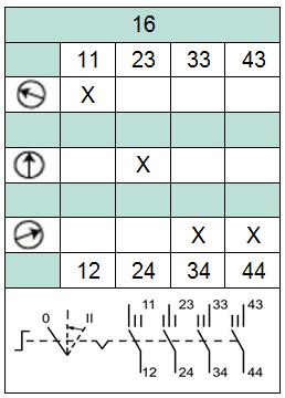
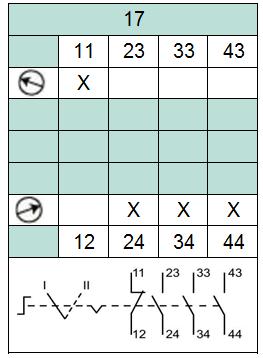
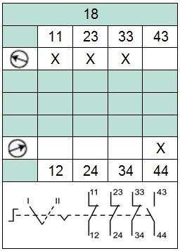


14 Ex de Control Switches, 4 Pole Rotary Switching locks Switching Diagrams 14
 LED Modules, base-mounted 10-28 V AC/DC LED Module, certified Ex de / Ex ia N Type Code 10-28 V AC/DC LED Module, certified Ex de NE 20-250 V AC/DC LED Module, certified Ex de")
15 Ex de / Ex ia LED Indicators Lens for LED Red indicator lens cover Green indicator lens cover Amber indicator lens cover White indicator lens cover lue indicator lens cover Type Code LR LG LO LW L Red LED Indicator (LR) LED Modules, base-mounted V AC/DC LED Module, certified Ex de / Ex ia N Type Code V AC/DC LED Module, certified Ex de NE V AC/DC LED Module, certified Ex de L V AC/DC LED Module, certified Ex de P ase-mounted LED Module Technical Data LED Modules Rated operating voltage (types N) Rated operating voltage (types L) Rated operating voltage (types P) V AC/DC V AC/DC V AC Terminals, max. core cross-section 2 x 2.5 mm 2 Power consumption 2 W Ex i data for application in connection with Ex-areas (types N) EC-Type Examination Certificate CML 16ATEX3339U Group, category, type of protection II 1G Ex ia IIC Ga IECEx approval IECEx CML U Voltage Ui 28 V Current Ii 93 ma Power Pi 0,651 W Internal capacitance Ci 0 Internal inductance Li 0 15


 20... 250 V AC/DC Terminals, max.")
16 Ex de uzzers and uzzers with Flashlight uzzer modules, lid-mounted uzzer with flashlight, red, V AC/DC uzzer with flashlight, red, V AC/DC uzzer, black, V AC/DC uzzer, black, V AC/DC Typ Code UZF1 UZF2 UZS1 UZS2 uzzer with flashlight uzzer Technical Data uzzer Sound level cm Rated operating voltage (types *1) V AC/DC Rated operating voltage (types *2) V AC/DC Terminals, max. core cross-section 2 x 2.5 mm 2 Power consumption 1 W 16
17 Ex e Ammeters Ammeter/Voltmeter Window with Mounting Kit Window including base mounting kit W Ammeter Units Ammeter 0-1 A, scales see below AA Ammeter 0-5 A, scales see below A Ammeter 0-10 A, scales see below AE Ammeter 4-20 ma, scale 4 20 / 40 ma included AC Ammeter Ammeter 0-20 ma, scale 0 20 / 40 ma included AD Ammeter Scales Ammeter scale / 5 A Ammeter scale / 12.5 A Ammeter scale / 25 A Ammeter scale / 50 A Ammeter scale / 75 A Ammeter scale / 125 A Ammeter scale / 150 A Ammeter scale / 200 A Ammeter scale / 250 A Ammeter scale / 300 A Ammeter scale / 375 A Ammeter scale / 500 A Ammeter scale / 750 A Ammeter scale / 1000 A Ammeter scale / 1250 A Ammeter scale / 1500 A Ammeter scale / 2000 A Ammeter scale / 2500 A Ammeter scale / 3000 A Ammeter scale / 5000 A lank ammeter scale Ammeter scale as per specification SA S SC SD SE SF SG SH SI SJ SK SL SM SN SO SP SQ SR SS ST SX SZ Technical Data Ammeter Rated operating voltage 500 V AC Rated operating current 20 ma / 1 A / 5 A / 10 A Terminals, max. core cross-section 2 x 2.5 mm 2 Accuracy class


18 Ex e Voltmeters Voltmeter Units Voltmeter 0-10 V, scale included V6 Voltmeter 0-25 V, scale included V1 Voltmeter 0-40 V, scale included V2 Voltmeter 0-50 V, scale included V7 Voltmeter V, scale included V8 Voltmeter V, scale included V9 Voltmeter V, scale included V3 Voltmeter V, scale included V4 Voltmeter V, scale included V5 Voltmeter For mounting kits see ammeters Technical Data Voltmeter Rated operating voltage 500 V AC Terminals, max. core cross-section 2 x 2.5 mm 2 Ex de Potentiometer Potentiometer Actuator Potentiometer actuator, black, labeled "0-10" R1 Potentiometer locks, base-mounted 500 Ω potentiometer Ω potentiometer Ω potentiometer Ω potentiometer Ω potentiometer 0 Potentiometer Actuator ase-mounted Potentiometer lock Technical Data Potentiometer Rated operating voltage max. 200 V AC max. 200 V DC Terminals, max. core cross-section 2 x 2.5 mm 2 2 x 2.5 mm 2 Power consumption 0.1 W 0.1 W 18


 Protective lid, plastic (ZA)")
")

19 Operator Accessories Accessory lanking plug K Small label holder with printed label as per specification ZS Large label holder with printed label as per specification ZL Emergency stop label, yellow, round, adhesive ZE Emergency stop label, yellow, rectangular, adhesive ZF Protective lid, plastic ZA Protective shroud for double pushbutton, stainless steel, padlockable ZH Protective shroud for small actuators, plastic, padlockable Z Small label holder (ZS) Protective shroud for pushbutton continuous operation, plastic, padlockable ZJ Emergency stop shroud, plastic, padlockable ZP Protective shroud, stainless steel ZC Protective shroud, stainless steel, padlockable ZD Locknut spanner, plastic TP Emergency stop label (ZE) lanking plug (K) Protective lid, plastic (ZA) Protective shroud for double pushbutton (ZH) Protective shroud for small actuators (Z) Shroud for pushbutton continuous operation (ZJ) Emergency stop shroud, plastic, padlockable (ZP) Protective shroud, stainless steel (ZC) Protective shroud, stainless steel, padlockable (ZD) 19
Terminal Boxes in Stainless Steel SLS**.T
 Features Variant options Stainless steel enclosures Suitable for installation in Zones 0, 1, 2, 21 and 22 Certified Ex e, Ex ia and Ex tb 6 enclosure size options Various terminal and cable gland configurations
Solutions Ex d IIB+H2, Stainless Steel EJBX*
 Features Assembly Examples Enclosures manufactured from AISI 316L stainless steel Suitable for operation in Zones 1, 2, 21 and 22 Certified Ex d IIB+H2 and Ex tb More than 20 enclosure size options Free
Solutions Ex d IIB+H2, Aluminum and Stainless Steel
 Features Assembly examples Enclosures manufactured from copper-free aluminum or AISI 316L stainless steel Suitable for operation in Zones 1, 2, 21 and 22 Certified Ex d IIB+H2 and Ex tb More than 40 enclosure
Assembly. Trunk IN + - S U, I U, I. Spur 1
 FieldBarrier FD0-FB-Ex.* Features Assembly outputs Ex ia IIC FieldBarrier in Zone /Div. Instruments in Zone 0.../Div. Short circuit current limitation per output For FOUNDATION Fieldbus H and PROFIBUS
SKX 16, 18, 20 II 2GD. Ex d e mb ia/ib IIC T4...T6 Gb Ex tb IIIC T80 C Db -20ºC Ta +50ºC -50ºC Ta +50ºC Degree of protection: IK 08
 Zone 1 21 22 2 SKX 16, 18, 20 IP 66 +50 C 20 Enclosures made of glassfibre reinforced polyester resin or stainless steel AISI 316L 3 basic enclosure sizes in GRP 3 basic enclosure sizes in stainless steel
Control Buttons / Switches for Panel Mounting Series 8003
 www.stahl.de > Different actuators pushbutton mushroom pushbutton mushroom stay-put button mushroom stay-put button with key lock key-operated button key-operated switch > 2 contact elements > Spring clamp
HKH Series. HAZCON Controls for Harsh and Hazardous Environments
 HKH Series HAZCON Controls for Harsh and Hazardous Environments Z A H LO C NON-METALLIC DIN RAIL MOUNT Component Mounting Rail Optional Customer I.D. Nameplate Optional Legend Plate Explosion Protective
Fieldbus Segment Protector F2-SP-IC* Features. Assembly. Function. Connection. Zone 2 Div. 2
 Fieldbus Segment Protector Features Assembly 4... 10 outputs Ex ic (FISCO or Entity) or non-incendive (Div 2) Advanced fault isolation at the spur Segment Protector in Zone 2/Div. 2 Instruments in Zone
M-0. M-0... series control, monitoring and signalling devices. Ex e
 M-0 The new Cortem M-0 series control, monitoring and signalling devices are installed as external accessories on '' enclosures and boards used in any industrial environment where an explosive atmosphere
ACTUATOR ASSEMBLIES FOR PANEL MOUNT APPLICATIONS
 Z A H LO C ACTUATOR ASSEMBLIES FOR PANEL MOUNT APPLICATIONS BASIC CATALOG NUMBERS HKHPBMMSS1 HKHPBMMTC1 HKHPBILLMM1 HKHPBMMMR1 HKHPBMMMB1 HKHPBMMMG1 HKHDBLPBMMGR1 HKHPBPMTMR1 HKHPBPMTMB1 HKHPBPMTMG1 HKHPBTMTMR1
9.6 Sales: Malux Finland Oy, P.O.Box 69, FI Porvoo, Phone , Fax ,
 E X - C O N T R O L S T A T I O N S Moulded plastic Version for Zone 1 and Zone 21 Even under the most adverse conditions, CEAG control stations can be used and operated reliably. The enclosures consist
5.1. GHG 26 / EXKO 2.. Ex-Safety Switches Rated current from 10 A A
 .1 GHG 26 / EXKO 2.. Ex-Safety Switches Rated current from 10 A - 630 A Safety for your protection CEAG safety switches can be protected against inadvertent switching on by our integrated locking facility
I Ex-control stations I
 Type 11 83 Type 11 82 Type 11 81 Technical data Ex-control stations Type 11 81 I Type 11 82 I Type 11 83 Marking accd. to 9/9/EC II 2 G Ex ed ib m IIC T6 II 2 D Ex td A21 IP66 T80 C EC-Type Examination
Versions. Version with K VS Version with K VS 2.0. Fig. 1: Type 3967 Solenoid Valve
 Type 367 Solenoid Valve Application Solenoid valve for controlling pneumatic linear actuators with NAMUR rib according to IEC 60534 or pneumatic rotary actuators with NAMUR interface according to VDI/VDE
Junction boxes for control, monitoring and control panel Ex tb
 Junction boxes for control, monitoring and control panel - Zone 21, 22 - Category 2D - Aluminium, reinforced polyester or stainless steel enclosures - Standard or custom products Inspection window Padlockable
JBEP Series Fiberglass Reinforced Polyester Terminal Junction Boxes for Instrumentation Applications Increased Safety. Factory Drilled and Equipped
 Enclosures and Junction Boxes Enclosures and Junction Boxes: Hazardous Location Outlet Boxes Applications Instrumentation junction boxes are used to run process or remote information to control room. For
Main current switches >180 A are realized in metal enclosures. Internationally approved.
 E X - M A I N C U R R E N T S W I T C H E S 10 A - 80 A (up to 630 A) CEAG main current switches in a number of versions can be protected against inadvertent switching on by our integrated locking facility
SPOOL VALVES solenoid air operated 1/4 to 1/2 tapped body and NAMUR for integrated pilot
 SPOOL VALVES operated / to / tapped body and NAMUR for integrated pilot ATEX /-/ Series - FEATURES The valves offer environmental protection against the ingress of liquids, dusts or other foreign matter
UNIK 5800/5900. Flameproof/Explosion-Proof Pressure Sensing Platform. GE Measurement & Control. High Quality. Features. Bespoke as Standard.
 GE Measurement & Control UNIK 5800/5900 Flameproof/Explosion-Proof Pressure Sensing Platform The 5800 and 5900 are compact and rugged versions of the high performance UNIK 5000 pressure sensing platform
HKH Series. HAZCON Controls for Harsh and Hazardous Environments
 (93) A ø 0.2" (ø 5.5) 1.9 (4 3.7" (93) B A " 0) 8" 0) HKH Series HAZCON Controls for Harsh and Hazardous Environments 0.2" (5.5) 0.2" (5.5) 3.1" (80) 2.8" (70) ø 0.2" (ø 5.5) 1.9" (48) 3.7" (93) A B 0.2"
I Ex-safety switches I
 EMERGENCY STOP EMERGENCY STOP Technical data Ex-safety switches 12 A Marking accd. to 94/9/EC II 2 G Ex de IIC T6 / II 2 D Ex td A21 IP66 T80 C EC-Type Examination Certificate PTB 99 ATEX 1164 PTB 00 ATEX
Flameproof - Group IIB or IIB + H 2 Carbon steel - DE8BC series. Painted steel. -40 C or -20 C C or +50 C or +60 C
 Enclosures Flameproof - Group IIB or IIB + 2 Carbon steel - DE8BC series The flameproof control cabinets DE8BC are designed for the control, automation, distribution boards, motor starters or any other
Data Sheet DS/NGB-EN Rev. B. Multi barriers. Measurement made easy. Fieldbus barrier for PROFIBUS PA for FOUNDATION Fieldbus-H1
 Data Sheet DS/NGB-EN Rev. B Multi barriers Measurement made easy Fieldbus barrier for PROFIBUS PA for FOUNDATION Fieldbus-H1 Change from two to one column Multi barriers Change from one to two columns
Control switch/load disconnect switch Series 8008
 > s Control switch with 2, 3 or 4 pole Load switch 3 pole + 1 auxiliary contact > Rated operational voltage up to 690 V AC > Positive opening contacts > Contacts suitable for EM-STOP > Isolating characteristics
*-JBSC-* Fieldbus junction box with integrated short-circuit current limitation
 Fieldbus Segment Protector Fieldbus junction box with integrated short-circuit current limitation Type code see overleaf Connection Shielding variations Main cable Trunk N Fieldbus distributor with individually
Position Switches Series 8070/2
 www.stahl.de > Ex e plastic enclosure > Operating temperature range -60 to +60 C > Dimensions and characteristic values according to EN 50041 > Degree of protection IP66 / IP67 > Extensive assortment of
I Ex-Safety switches I
 3-pole, 20 A Technical data Ex-Safety switch 20 A for variable-speed three-phase drives Marking to 94/9/EC II 2 G Ex ed ia IIC T6 / II 2 D Ex td A21 IP66 T80 C EC-Type Examination Certificate PTB 99 ATEX
Linear Luminaire for Fluorescent Lamps Series EXLUX 6401
 > As wall, ceiling and pendant light fitting or pole mounted light fitting > Version with 2 lamps: 18 W, 36 W and 58 W > Central locking > All-pole disconnection by means of an N/C switch when the lamp
2.4. Ex-Emergency light fittings with a self-contained battery system for fluorescent lamps
 .4 Ex-Emergency light fittings with a self-contained battery system for fluorescent lamps ellk 18/18 NE / ellk 36/36 NE / ellm 18/18 NE (Zone 1,, 1, ) If you need a reliable and decentralized emergency
Linear Luminaire for Fluorescent Lamps Series ECOLUX METAL 6010/1
 > For use in Zones 1, 2, 21, 22 and safe area > 2-lamp version: 18 W 36 W > Housing made of sheet steel or stainless steel SS304 / > Quick fasteners www.stahl.de 15709E00 The light fittings of Series ECOLUX
Direct-acting 3/2 way plunger valve
 Direct-acting 3/2 way plunger valve Direct-acting, compact valve with diameter of up to DN 2.5 Vibration-proof, bolted coil system Banjo threaded connection for direct mounting on pneumatic valves Type
Position Switches Series 8060/2
 www.stahl.de > Ex e plastic enclosure > Operating temperature range -60 to +60 C > Dimensions and characteristic values according to EN 50047 > Degree of protection IP66 / IP67 > Extensive assortment of
Type Z & Ex pz purge and pressurization system
 Type Z & Ex pz purge and pressurization system Features 100% automatic purge and pressurization system including purging, temperature and leakage control, alarming and system power Third party approvals
Thermocouple For additional thermowell, flameproof enclosure (Ex d) Model TC10-L
 Model TC10-L") Temperature Thermocouple For additional thermowell, flameproof enclosure (Ex d) Model TC10-L WIKA data sheet TE 65.12 for further approvals see page 2 Applications Chemical industry Petrochemical industry
Temperature Thermocouple For additional thermowell, flameproof enclosure (Ex d) Model TC10-L WIKA data sheet TE 65.12 for further approvals see page 2 Applications Chemical industry Petrochemical industry
L(+) SV1 N(-) NC. Terminal Block Connections L (+) N (-) SV1 K2 K1. Refer to "General Notes Relating to Pepperl+Fuchs Product Information".
 SV1 N(-) NC. Terminal Block Connections L (+) N (-) SV1 K2 K1. Refer to General Notes Relating to Pepperl+Fuchs Product Information.") Type Z & Ex pz purge and pressurization system Features 100% automatic purge and pressurization system including purging, temperature and leakage control, alarming and system power Third party approvals
Type Z & Ex pz purge and pressurization system Features 100% automatic purge and pressurization system including purging, temperature and leakage control, alarming and system power Third party approvals
Load disconnect switch Series 8146/5-V11
 www.stahl.de Load disconnect switch > Motor switching capacity AC-3 and AC-23 acc. to DIN VDE 0660 part 107 IEC/EN 60947-3 > Isolating characteristics acc. to IEC/EN 60947-3 > Positive opening operation
I Ex-safety switches I
 3-pole, 20 A Technical data Ex-safety switches 20 A for controlled three-phase drives Marking accd. to 94/9/EC II 2 G Ex ed ia IIC T6 / II 2 D Ex td A21 IP66 T80 C EC-Type Examination Certificate PTB 99
T 3965 EN Type 3965 Solenoid Valve Island To control pneumatic actuators
 T 365 EN Type 365 Solenoid Valve Island To control pneumatic actuators Application The Type 365 Solenoid Valve Island is a compact solution for the central control of pneumatic actuators in chemical and
Position Switches Series 8074/2
 www.stahl.de > Ex e metal enclosure > Operating temperature range -40 C... +70 C > Dimensions and characteristic values according to EN 50041 > Degree of protection IP66 > Extensive assortment of actuators,
Resistance thermometer For additional thermowell, flameproof enclosure (Ex d) Model TR10-L
 Model TR10-L") Temperature Resistance thermometer For additional thermowell, flameproof enclosure (Ex d) Model TR10-L WIKA data sheet TE 60.12 for further approvals see page 2 Applications Chemical industry Petrochemical
Temperature Resistance thermometer For additional thermowell, flameproof enclosure (Ex d) Model TR10-L WIKA data sheet TE 60.12 for further approvals see page 2 Applications Chemical industry Petrochemical
Spring loaded resistance thermometer
 Spring loaded resistance thermometer THERMOWELL & REPLACEABLE INSERT C200-201-204-205-260-262 CONFIGURATIONS Ex ia RTD Product series PT100RI/WI C200 C201 C204 C205 C260 C262 2 Features assembly The industrial
Compact pressure switch Model PCS
 Mechatronic pressure measurement Compact pressure switch Model PCS WIKA data sheet PV 33.30 for further approvals see page 4 Process Compact Series Applications Pressure monitoring and control of processes
L(+) SV1 N(-) NC. Terminal Block Connections L (+) N (-) SV1 K2 K1. Refer to "General Notes Relating to Pepperl+Fuchs Product Information".
 SV1 N(-) NC. Terminal Block Connections L (+) N (-) SV1 K2 K1. Refer to General Notes Relating to Pepperl+Fuchs Product Information.") Type Z & Ex pz purge and pressurization system Features 100% automatic purge and pressurization system including purging, temperature and leakage control, alarming and system power Third party approvals
Type Z & Ex pz purge and pressurization system Features 100% automatic purge and pressurization system including purging, temperature and leakage control, alarming and system power Third party approvals
Clarian uk ltd SWITCHES AND CONTROLS TOP-TECHNIC TOP-TECHNIC TOP-TECHNIC TOP-TECHNIC TOP-TECHNIC TOP-TECHNIC.
 SWITCHES AND CONTROLS TOP-TECHNIC TOP-TECHNIC CONTROL UNITS SWITCH DISCONNECTORS & CAM SWITCHES TOP-TECHNIC TOP-TECHNIC EMERGENCY STOP MAIN SWITCHES MAIN SWITCHES TOP-TECHNIC TOP-TECHNIC CAM SWITCHES FOR
New products Ex Equipment 2015
 New products Ex Equipment 2015 ROSE Systemtechnik GmbH ROSE Systemtechnik GmbH was founded in Porta Westfalica, Germany, in 199 and is today one of the world s leading and innovative providers of industrial
Compact Sheet-steel Emergency Light Fitting Series 6118/1
 www.stahl.de Compact Sheet-steel Emergency Light Fitting > Electronic ballast with integrated emergency light electronics for emergency light mode in case of power failure, charging of battery and automatic
9 Control Equipment. Control Unit System Series ConSig 8040
 9 Control Equipment Control Unit System Explosion protection to CENELEC IEC NEC Can be used in Zone 1 and Zone 2 Standard and customized units 3 sizes available Enclosures in glass fibre reinforced polyester
STAINLESS STEEL PANEL MOUNT
 Z A H LO C STAINLESS STEEL PANEL MOUNT Optional Legend Plate Cover Screw Retaining Washer Panel Mount Bracket Explosion Protective LED Pilot Light Stainless Steel Washer Actuator Spacer Locknut Explosion
Solenoid Valve Island Type 3965
 Solenoid Valve Island Type 365 for the control of pneumatic actuators General The Type 365 Solenoid Valve Island is a compact solution for the centralized control of pneumatic actuators in chemical and
Compact Sheet-Steel Light Fittings Series 6114/1
 > As 1- or 3-lamp version > Versions Pendant fitting Wall-mounting fitting Flush mounted fitting > Powder-coated steel or stainless steel > Central lock > All pole disconnection via NC switch in positive
Ex d. S.1 series. - Zone 1, 2, 21, 22 - Group IIC - Aluminium junction boxes - Wide selection of models - IP66 / 67. SSC series
 Ex d S S.1 series - Zone 1, 2, 21, 22 - Group IIC - Aluminium junction boxes - Wide selection of models - IP66 / 67 SSC series Temperature sensor box SWS series SF series A.117 S... series Junction boxes
TERMINAL BOXES FOR HARSH & HAZARDOUS ENVIRONMENTS
 OSUR CL HA ES EN KILLARK Z LO C SJIC SERIES TERMINAL BOXES FOR HARSH & HAZARDOUS ENVIRONMENTS Screw cover style, with or without continuous hinge 3/16 (5mm) wide flat flange for maximum gasket surface
Leading the way in hazardous areas Features EATON
 .2 Ex-escape sign luminaires EXIT for Zone 1 and Zone 21 / Exit 2 for Zone 2 and Zone 22 Moulded plastic version with LED-technique Leading the way in hazardous areas The EXIT series of explosionprotected
HTSB system System overview
 HTSB system System overview Easy planning of heating circuits Simple installation on site Wide operating temperature range The BARTEC HTSB heating system covers a wide range of applications in trace heating.
Emergency Light Fitting for Fluorescent Lamps Series 6009
 > As wall, ceiling and pendant light fitting or pole mounted light fitting > Version with 2 lamps: 18 W and 36 W > Central locking > All-pole disconnection via N/C switch when opening light fitting or
Control Buttons Series 8082
 www.stahl.de > Contact element with 1 NO contact 1 NC contact, positive opening > Contact material silver-nickel or gold-plated > 9 different actuators Push Mushroom push Selector switch Rotary actuator
Magnetic float switch For vertical installation Model FLS (models with Ex approval: 60, AL-ADF)
") Level measurement Magnetic float switch For vertical installation Model FLS (models with Ex approval: 60, AL-ADF) TC Fluid Control WIKA data sheet LM LM 3001 30.01 for further approvals see page 3 Applications
Level measurement Magnetic float switch For vertical installation Model FLS (models with Ex approval: 60, AL-ADF) TC Fluid Control WIKA data sheet LM LM 3001 30.01 for further approvals see page 3 Applications
ILED Aquarius Illuminated Windsock. User Manual
 Contents 1. Safety... 3 2. Warranty... 3 2.1 General... 3 2.2 Life span... 3 3. Type plate... 4 3.1 The light fitting has a type plate:... 4 3.2 The junction box has a type plate:... 5 4. Product Description...
ANKERSMID Temperature controller ATC 510/520/525 for wall-mounting. Application
 2-3.1 ATC 510/520/525 for wall-mounting Application The ATC 510/5205/525 is a modern microprocessor-based (PID) control device featuring easy handling and a digital display. The clear design of the operator
CONTROL STATIONS. For Harsh & Hazardous Environments.
 CONTROL STATIONS For Harsh & Hazardous Environments www.ehawke.com Hubbell Harsh & Hazardous Extreme environments demand superior performance, which is why you will find Hubbell products and systems installed
Intrinsically safe presure transmitters for hazardous environments Type MBS 4201, MBS 4251, MBS 4701 and MBS Technical brochure
 Intrinsically safe presure transmitters for hazardous environments Type MBS 4201, MBS 4251, MBS 4701 and MBS 4751 Technical brochure Features Ex ll 1G EEx ia llc T4 - T6 in compliance with ATEX 100a Applicable
HONDA NO ENGINE DESCRIPTION FULL SET HEAD SET CYL. HEAD CHK-9827SK 061A1-PH A1-PH2-010 CHK-9845SA PR PR3-000
 1 A20A ACCORD 2000 1985-ON 1955CC CA5-110 86mm 2 B16A INTEGRA CRX 1991-1595CC CHK-9827SK 061A1-PH4-000 061A1-PH2-010 CHK-9845SA 06110-PR3-000 06111-PR3-000 VHK-9827SK 061A1-PH4-000H VHK-9845SA 061A1-PR3-010H
RJ45 10/100/1000 Base-TX Tab down 1x4 Jack with Magnetic Module. Storage temperature range: -40ºC to +85ºC. LEDs. EMI Fingers (see Mechanical)
") RJ45 0/00/000 Base-TX Tab down x4 Jack with Magnetic Module ARJ4A 59. x 3.60 x.50 mm / 5.40 x 3.00 x 0.54mm FEATURES: Tab down Available with or without LED Suitable CAT 5 & 6 cable and UTP Comply IEEE
RJ45 0/00/000 Base-TX Tab down x4 Jack with Magnetic Module ARJ4A 59. x 3.60 x.50 mm / 5.40 x 3.00 x 0.54mm FEATURES: Tab down Available with or without LED Suitable CAT 5 & 6 cable and UTP Comply IEEE
Cross Reference FUEL INJECTION CORPORATION. Bosch to FIC Part # FIC # Bosch to FIC Part # FIC # Bosch to FIC Part # FIC # Part # FIC # Part # FIC #
 0 261 200 007 150083 0 280 000 139 140139 0 280 000 563 140563 0 280 100 053 200053 0 280 150 725 380725 0 261 200 008 150084 0 280 000 141 140141 0 280 000 564 140564 0 280 100 054 200054 0 280 150 730
L1 = Solder terminal 2.8 x 0.5 mm Ø Behind panel
 Raised design Emergency-stop switch, foolproof EN IEC 60947-5-5, IP 65 Equipment consisting of (schematic overview) L1 35.6 6 max. 59.5 41 18x24 Actuator Product can differ from the current configuration.
Thermocouple For additional thermowell Model TC10-B
 Temperature Thermocouple For additional thermowell Model TC10-B WIKA data sheet TE 65.02 for further approvals see page 2 Applications Machine building, plant and vessel construction Energy and power plant
I 16A 2-pole up to 50 V I I 16A 3-pole up to 50 V I
 I 6A 2-pole up to 50 V I I 6A 3-pole up to 50 V I Flange socket Coupler Technical data Ex-plugs and receptacles for low voltage, 2- and 3-pole acc. to IEC 60309-/2 Marking accd. to 94/9/EC II 2 G Ex de
EA series housings. Selection diagram. 125 General Catalogue HMI ACTUATORS ACCESSORIES COVERS. emergency button Ø 40 push-pull, windowed
 EA series housings Selection diagram ACTUATORS Ø 40 push-pull Ø 40 push-pull, windowed Ø 40 rotary release Ø 40 rotary release, windowed Ø 40 key release selector switch with short handle knob selector
PEPPEX SERIES PRESURIZED ENCLOSURES ATEX EX P - PX - PY - PZ LARGE INTERIOR SPACE SIMPLIFYING CONNECTION WORK. Zones 1, 2, 21 and 22
 LARGE INTERIOR SPACE SIMPLIFYING CONNECTION WORK PEPPEX SERIES PRESURIZED ENCLOSURES EX P - PX - PY - PZ Zones 1, 2, 21 and 22 PRESSURIZED EX P CABINETS PEPPEX SERIES 4 CABLE ENTRY COVER IP65 13 CABLE
GHG43 Series Control Stations
 GHG43 Series Control Stations Nonmetallic or 316L Stainless Steel UL/cUL listed Cl. I, Div. 2, Groups A, B, C, D Cl. I, Zones 1 and 2, (A) Ex de IIB + H2 T6 Cl. II, Div. 1, Groups E, F, G (cul) PTB ATEX
GuaRdboX - Gd series IOM (Installation, Operation & Maintenance Manual) 0100-ENG rev.4
 0100-ENG rev.4") 1. Introduction: This instruction manual contains important information regarding the safety instructions, installation, operation, maintenance and storage of the Guardbox limit switch boxes. The limit
1. Introduction: This instruction manual contains important information regarding the safety instructions, installation, operation, maintenance and storage of the Guardbox limit switch boxes. The limit
1/122 Sales: Malux Finland Oy, P.O.Box 69, FI Porvoo, Phone , Fax ,
 1/122 Explosion Protected Safety Luminaire and Escape Sign Luminaires Approved for explosive areas with gas explosion-hazard zones 1 and 21 as well as dust explosion-hazard zones 2 and 22 High IP66 protection
ILED Dorado. User Manual
 10NM U-code Medium Intensity Obstruction Light Helideck Status Light 15NM U-code Contents 1. Safety... 3 2. Warranty... 3 2.1 General... 3 2.2 Life span... 3 3. Type plate... 4 4. Product Description...
Dimensions shown apply to both Stainless Steel and Mild Steel S1, SF*1 = 162, S2, SF*2, S2L, SF*2L = 170, S3, SF*3 = 250,
 Assembly Instructions for junction boxes type: Assembly Instructions for: S1 to S / SFI1 to SFI / SFE1 to SFE S1 to S Junction Boxes MS1 to MS Junction Boxes IMPORTANT: This document should be read carefully
Linear Luminaire for Fluorescent Lamps Series ECOLUX 6600
 > 2-lamp version: 18 W 36 W 58 W > Enclosure in polyester resin, glass fibre reinforced and cover in polycarbonate, impact-resistant > Quick fasteners www.stahl.de 10032E00 The light fittings series 6600
Plug and Socket Devices SolConeX 16 A Series 8570
 Plug and Socket Devices SolConeX 16 A Series 8570 www.stahl.de > Switch socket / plug 16 A > Minimal force required to insert and remove > Can be optionally equipped with an auxiliary contact for control
USER MANUAL FOR THE BULKHEAD LIGHT FITTING, TYPE /..
 d.o.o. tel. 049 222 900, fax 049 426 450 e-mail: tepex@tepex.hr www.tepex.hr USER MANUAL FOR THE BULKHEAD LIGHT FITTING, TYPE 0403.24/.. No: TEPEx.RS.077 Rev : 0 Date: 02.2016. CONTENT 1. Manufacturer
4.6. Ex-Floodlights for high-pressure discharge lamps, series FZD 04 / FZD EN. (Zone 1, 2, 21, 22)
") .6 Ex-Floodlights for high-pressure discharge lamps, series FZD 0 / FZD EN (Zone 1, 2, 21, 22) The maintenance- and installation-friendly FZD 0 floodlights for harsh operating conditions Due to the spatial
.6 Ex-Floodlights for high-pressure discharge lamps, series FZD 0 / FZD EN (Zone 1, 2, 21, 22) The maintenance- and installation-friendly FZD 0 floodlights for harsh operating conditions Due to the spatial
3/2, 5/2, 5/2 bistable and 5/3 way pneumatic solenoid valve
 3/2, 5/2, 5/2 bistable and 5/3 way pneumatic solenoid valve Type 6518 Type 6519 Type 6518/6519 can be combined with... Single or block mounting Suitable for outdoor and chemical atmospheres Suitable for
ALUMINIUM AND STAINLESS STEEL ENCLOSURES - EJB... SERIES
 Ex d IIB+H 2 ALUMINIUM AND STAINLESS STEEL ENCLOSURES - EJB... SERIES ALUMINIUM ENCLOSURES STAINLESS STEEL ENCLOSURES EJB... series enclosures offer Ex d IIB +H 2 mode of protection. These enclosures are
Plastic enclosures compact Of polycarbonate. Degree of protection: IP 66, 67, 69K UL type1, 3R, 4, 4X, 12, 13
 Pilot devices, 22 mm Assembled stations and enclosures Assembled stations There are assembled stations of two types: In plastic enclosures and in metallic enclosures Both types of enclosures are available
The cover screws and all other external metal parts are made of stainless steel (AISI 316L). International approvals
. International approvals") E X - J U N C T I O N B O X Plastic version for Zone 1,, 1 and The robust junction boxes made of plastic and light alloy are featured by their simple mounting and installation capability and their design.
E X - J U N C T I O N B O X Plastic version for Zone 1,, 1 and The robust junction boxes made of plastic and light alloy are featured by their simple mounting and installation capability and their design.
Accord DS/DM Series UltraSwitch Switch box
 Accord DS/DM Series UltraSwitch Switch box Features DS/DM Series Ultraswitch Description The DS/DM Series UltraSwich from Flowserve Accord provides cost efficient, accurate and reliable position signaling
4.7. Ex-Floodlights for high-pressure discharge lamps, series FZD 04 (Zone 1, 2, 21, 22)
") .7 Ex-Floodlights for high-pressure discharge lamps, series FZD 0 (Zone 1, 2, 21, 22) The maintenance- and installation-friendly FZD 0 floodlights for harsh operating conditions Due to the spatial separation
.7 Ex-Floodlights for high-pressure discharge lamps, series FZD 0 (Zone 1, 2, 21, 22) The maintenance- and installation-friendly FZD 0 floodlights for harsh operating conditions Due to the spatial separation
Resistance thermometer Without thermowell Model TR10-H
 Temperature Resistance thermometer Without thermowell Model TR10-H WIKA data sheet TE 60.08 for further approvals see page 2 Applications For direct installation into the process Machine building Motors
CONTROL STATIONS. For Harsh & Hazardous Environments.
 CONTROL STATIONS For Harsh & Hazardous Environments www.ehawke.com Hubbell Harsh & Hazardous Extreme environments demand superior performance, which is why you will find Hubbell products and systems installed
Operating Instructions
 Important Information: These instructions contain safety information, read and follow them carefully. Dialight will not accept any responsibility for injury, damage or loss which may occur due to incorrect
Terminal Boxes TNCN. Explosion protection Marking
 Terminal boxes TNCN Terminal Boxes TNCN The TNCN range comprises many standard sizes of enclosures manufactured in stainless steel 316L for maximum environmental protection. The main box is manufactured
EXEL-L. Detail of the internal side. Transparent polycarbonate
 EXEL-L - Complete with high efficiency LED tubes - Quick access to the internal electrical equipment - Double locking system operated by hexagonal-head tool - Zone 1, 2, 21, 22 Reinforced polyester resin
INTERNATIONAL METAL ENGINEERING
 INSTRUMENT ENCLOSURES, JUNCTION BOXES, STOPPING PLUGS, TEMPERATURE ASSEMBLIES AND A WIDE RANGE OF INDICATORS, TRANSMITTERS AND BATCH CONTROLLERS FM, CSA, ATEX, IECEx CERTIFIED OCTOBER 2015 INTERNATIONAL
Compact differential pressure switch Models DC, DCC
 Mechatronic pressure measurement Compact differential pressure switch Models DC, DCC WIKA data sheet PV 35.40 Process Compact Series Applications Differential pressure monitoring and control of processes
INSTRUCTION MANUAL (ATEX / IECEx)
") INSTRUCTION MANUAL (ATEX / IECEx) BExBGL2D LED BEACON For use in Flammable Gas and Dust Atmospheres BExBGL2D 1) Warnings DO NOT OPEN WHEN AN EXPLOSIVE ATMOSPHERE IS PRESENT DO NOT OPEN WHEN ENERGIZED POTENTIAL
INSTRUCTION MANUAL (ATEX / IECEx) BExBGL2D LED BEACON For use in Flammable Gas and Dust Atmospheres BExBGL2D 1) Warnings DO NOT OPEN WHEN AN EXPLOSIVE ATMOSPHERE IS PRESENT DO NOT OPEN WHEN ENERGIZED POTENTIAL
Linear fittings EVDL LED fitting - zones 21, & 22
 ABB DTS LINEAR FITTINGS - EVDL LED FITTING - ZONES 21 & 22 77 Linear fittings EVDL LED fitting - zones 21, & 22 LED Features Operating life up to 100 000 h High lumen output - 5 000 lumens with 100% yield
11mm Slot Label S1 = 162, S2 = 170, S3 = 250, S4 = 305, S5 = 330, S6 = 410, S7 = 490, S8 = 570, S9 = 650. Maximum Power Dissipation (Watts) T** T**
 T** T**") Assembly Instructions for: S1 Assembly to S Junction Instructions Boxes for: MS1 to MS Junction Boxes Boxes MS1 to MS Junction Boxes IMPORTANT: This document should be read carefully before commencing
Assembly Instructions for: S1 Assembly to S Junction Instructions Boxes for: MS1 to MS Junction Boxes Boxes MS1 to MS Junction Boxes IMPORTANT: This document should be read carefully before commencing
A good connection. International approvals.
 E X - P L U G S A N D R E C E P T A C L E S 0 A to 25 A plugs and receptacles plastic version for zone, 2, 2 and 22 A good connection Providing electrical energy there, where it is most needed even in
INSTRUCTION MANUAL (ATEX / IECEx)
") INSTRUCTION MANUAL (ATEX / IECEx) BExBG10D-P and BExBG15D-P Flameproof Xenon Beacons For use in Flammable Gas and Dust Atmospheres BExBG10D-P / BExBG15D-P 1) Warnings DO NOT OPEN WHEN AN EXPLOSIVE ATMOSPHERE
INSTRUCTION MANUAL (ATEX / IECEx) BExBG10D-P and BExBG15D-P Flameproof Xenon Beacons For use in Flammable Gas and Dust Atmospheres BExBG10D-P / BExBG15D-P 1) Warnings DO NOT OPEN WHEN AN EXPLOSIVE ATMOSPHERE
ABCS GRP Control Stations
 ABCS GRP Control Stations Application Industrial and Hazardous areas IP65/66 Protection Degree IP66 (IP65 when fitted with an ammeter) Certification ATEX & IECEx Ex e II T4 or Ex ed IIC T4 Material Glass
ABG Cable Glands Installation Procedure
 ABG Cable Glands Installation Procedure ABG Cable Gland Range Baseefa 16ATEX0004X IECEx BAS 16.0011X Installation, Operation and Maintenance Instructions Material: Brass/ Brass with Nickel plated and Stainless
P, I, A. Command and control stations Ex e
 P, I, A Command and control stations - Group IIC - Zone 1, 2, 21, 22 - Aluminium, reinforced polyester or stainless steel enclosures - Standard or custom products - Speed of delivery, designed to customer
E II 3 (1) G Ex na [ia Ga] IIC/IIB T4 Gc
![E II 3 (1) G Ex na [ia Ga] IIC/IIB T4 Gc](/thumbs/74/70015027.jpg "E II 3 (1) G Ex na [ia Ga] IIC/IIB T4 Gc") 900/77-80-094-001 158877 For the intrinsically safe operation of a wide range of devices, such as HART transmitters, solenoid valves, sensors, zero-potential contacts and many more compact, space-saving
900/77-80-094-001 158877 For the intrinsically safe operation of a wide range of devices, such as HART transmitters, solenoid valves, sensors, zero-potential contacts and many more compact, space-saving