Original instructions LineStrong-series Emergency Stop Grab Wire Safety Switch
|
|
|
- Julian Dawson
- 5 years ago
- Views:
Transcription


1 Original instructions LineStrong-series Emergency Stop Grab Wire Safety Switch ABB AB / Jokab Safety Varlabergsvägen 11, SE Kungsbacka, Sweden
2 Read and understand this document Please read and understand this document before using the products. Please consult your ABB/JOKAB SAFETY representative if you have any questions or comments. WARRANTY ABB/JOKAB SAFETY s exclusive warranty is that the products are free from defects in materials and workmanship for a period of one year (or other period if specified) from date of sale by ABB/JOKAB SAFETY. ABB/JOKAB SAFETY MAKES NO WARRANTY OR REPRESENTATION, EXPRESSED OR IMPLIED, REGARDING NON-INFRINGEMENT, MERCHANTABILITY, OR FITNESS FOR PARTICULAR PURPOSE OF THE PRODUCTS, ANY BUYER OR USER ACKNOWLEDGES THAT THE BUYER OR USER ALONE HAS DETERMINED THAT THE PRODUCTS WILL SUITABLY MEET THE REQUIREMENTS OR THEIR INTENDED USE. ABB/JOKAB SAFETY DISCLAIMS ALL OTHER WARRANTIES, EXPRESSED OR IMPLIED. LIMITATIONS OF LIABILITY ABB/JOKAB SAFETY SHALL NOT BE RESPONSIBLE FOR SPECIAL, INDIRECT, OR CONSEQUENTIAL DAMAGES, LOSS OF PROFITS OR COMMERCIAL LOSS IN ANY WAY CONNECTED WITH THE PRODUCTS, WHETHER SUCH CLAIM IS BASED ON CONTRACT, WARRANTY, NEGLIGENCE, OR STRICT LIABILITY. In no event shall responsibility of ABB/JOKAB SAFETY for any act exceed the individual price of the product on which liability asserted. IN NO EVENT SHALL ABB/JOKAB SAFETY BE RESPONSIBLE FOR WARRANTY, REPAIR, OR OTHER CLAIMS REGARDING THE PRODUCTS UNLESS ABB/JOKAB SAFETY S ANALYSIS CONFIRMS THAT THE PRODUCTS WERE PROPERLY HANDLED, STORED, INSTALLED, AND MAINTAINED AND NOT SUBJECT TO ABUSE, MISUSE, OR INAPPROPRIATE MODIFICATION OR REPAIR. SUITABILITY FOR USE ABB/JOKAB SAFETY shall not be responsible for conformity with any standards, codes, or regulations that apply to the combination of products in the customer s application or use of the product. At the customer s request, ABB/JOKAB SAFETY will provide applicable third party certification documents identifying ratings and limitations of use that apply to the products. This information by itself is not sufficient for a complete determination of the suitability of the products in combination with the end product, machine, system, or other application or use. The following are some examples of applications for which particular attention must be given. This is not intended to be an exhaustive list of all possible uses of the products, nor is it intended to imply that the uses listed may be suitable for the products: Outdoor use, uses involving potential chemical contamination or electrical interference, or conditions or uses not described in this document. Nuclear energy control systems, combustion systems, railroad systems, aviation systems, medical equipment, amusement machines, vehicles, and installations subject to separate industry or government regulations. Systems, machines, and equipment that could present a risk to life or property. Please know and observe all prohibitions of use applicable to the products. NEVER USE THE PRODUCTS FOR AN APPLICATION INVOLVING SERIOUS RISK TO LIFE OR PROPERTY WITHOUT ENSURING THAT THE SYSTEM AS A WHOLE HAS BEEN DESIGNED TO ADDRESS THE RISKS, AND THAT THE ABB/JOKAB SAFETY PRODUCT IS PROPERLY RATED AND INSTALLED FOR THE INTENDED USE WITHIN THE OVERALL EQUIPMENT OR SYSTEM. PERFORMANCE DATA While every effort has been taken to ensure the accuracy of the information contained in this manual ABB/JOKAB SAFETY cannot accept responsibility for errors or omissions and reserves the right to make changes and improvements without notice. Performance data given in this document is provided as a guide for the user in determining suitability and does not constitute a warranty. It may represent the result of ABB/JOKAB SAFETY S test conditions, and the users must correlate it to actual application requirements. Actual performance is subject to the ABB/JOKAB SAFETY Warranty and Limitations of Liability. 2TLC172248M0201, rev. A 2
3 Table of Contents 1 Introduction... 4 Scope... 4 Audience... 4 Prerequisites... 4 Special notes Overview... 5 General description... 5 Safety regulations... 5 Function description for the variants Connections Installation and maintenance Application example Model overview Accessories Technical data LineStrong LineStrong2 series LineStrong3 series EC Declaration of conformity TLC172248M0201, rev. A 3
4 1 Introduction Scope The purpose of these instructions is to describe the Emergency Stop Grab Wire Safety Switch system LineStrongseries, and to provide the necessary information required for assembly, installation, checks and adjustments after installation, and maintenance. The instructions also include information necessary to connect LineStrong to a safety circuit. Audience This document is intended for authorized installation personnel. Prerequisites It is assumed that the reader of this document has knowledge of the following: Basic knowledge of ABB/Jokab Safety products. Knowledge of machine safety. Special notes Pay attention to the following special notes in the document: Warning! Caution! NB: Danger of severe personal injury! An instruction or procedure which, if not carried out correctly, may result in injury to the technician or other personnel. Danger of damage to the equipment! An instruction or procedure which, if not carried out correctly, may damage the equipment. Notes are used to provide important or explanatory information. 2TLC172248M0201, rev. A 4
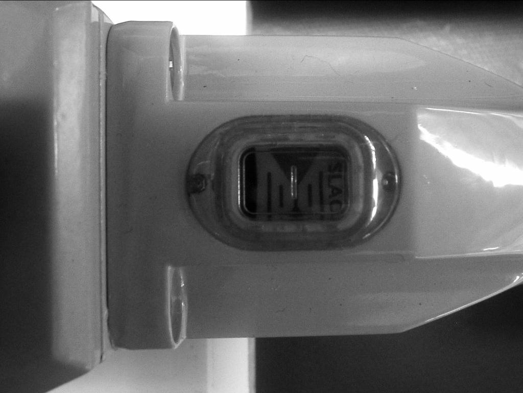
5 2 Overview General description All ABB Jokab Safety Emergency strop grab wire safety switches conform to European Standard EN ISO and IEC They have a positive mechanical linkage between the switch contacts and the wire as per IEC The emergency stop switches are brought into the operational condition by pre-tensioning the wire by use of a tensioner / gripper device which clamps the wire and then hooks to the switch eyebolts. Correct tension can be observed by viewing the tension indicator on the switch housing. Once tensioned the switch contact blocks can be set to the operational condition (safety contacts closed, auxiliary contacts open) by pressing a blue reset button on the switch cover. All of the grab wire safety switches have wire-breakage monitoring. On pulling or breakage (tension loss) of the wire, the safety contacts are positively opened and the auxiliary contacts are closed. The switches are mechanically latched and can then only be returned to the operational condition by a pressing the reset button as required by EN ISO Safety regulations Warning! Carefully read through this entire manual before using the device. The devices shall be installed by a trained electrician following the Safety regulations, standards and the Machine directive. Failure to comply with instructions, operation that is not in accordance with the use prescribed in these instructions, improper installation or handling of the device can affect the safety of people and the plant. For installation and prescribed use of the product, the special notes in the instructions must be carefully observed and the technical standards relevant to the application must be considered. In case of failure to comply with the instructions or standards, especially when tampering with and/or modifying the product, any liability is excluded. 2TLC172248M0201, rev. A 5
6 Function description for the variants LineStrong1 LineStrong1 is a compact and small, yet robust switch that can handle wires up to 30 meters on a single switch (50 meters on two switches). When someone pulls the wire of Linestrong1 or if the wire is broken, the switch goes to a safe state, e.g. the machine is emergency-stopped. After a emergency stop the LineStrong1 needs to be reset to be able to run again and this is made on the local reset button. LineStrong1 is equipped with an indication of how taut the wire is, which make the installation or adjustment easy. The LineStrong1 is made of a rugged die cast housing with a rating of IP67. A positive forced connection provides a forced disconnect of the safety contacts when the wire is being pulled or broken. The design of the LineStrong1 ensures that the contacts will not fail or be held in a normally closed position, due to failure of the spring mechanism or that welding/sticking of the contacts can occur. The LineStrong1 switch has 2NC and 2NO contacts. Up to 50 m 500 mm Every 3 meter Every 3 meter 500 mm eyebolt Up to 50 m 500 mm Every 3 meter Every 3 meter 500 mm eyebolt Safety Spring 1) LineStrong1 with another LineStrong1 2) LineStrong1 with safety spring 2TLC172248M0201, rev. A 6
7 LineStrong2 LineStrong2 is a robust switch that can handle wires up to 80 meters on a single switch (100 meters on two switches). When someone pulls the wire of LineStrong2 or if the wire is broken, the switch goes to a safe state, e.g. the machine is emergency-stopped. After a emergency stop the LineStrong2 needs to be reset to be able to run again and this is made with the local reset button. Additional features on the LineStrong2 are a "normal" emergency stop that is fitted on the side of the grab wire safety switch and also a two coloured LED for indication. LineStrong2 is equipped with an indication of how taut the wire is, which make the installation and adjustment easy. Depending on the environment where the switch will be used, different material can be chosen for the LineStrong2. The basic version has a rugged yellow die cast housing with a rating of IP67. In severe applications as for food processing and chemical industry there is a LineStrong2Z with a total rugged stainless steel 316 body. This version has IP69K enclosure protection (maintained by a double seal lid gasket and seals) and can be high pressure hosed with detergent at high temperature. LineStrong2 also exist in a version(linestrong2zx) with certified explosion proof contact block. LineStrong2ZX is in stainless steel and can be used in European Zone 1, 2, 21,22 enviroments. (Gas and Dust) A positive forced connection provides a forced disconnect of the safety contacts when the wire is being pulled or broken. The design of the LineStrong2 ensures that the contacts will not fail or be held in a normally closed position, due to failure of the spring mechanism or that welding/sticking of the contacts can occur. The LineStrong2 switch has 2NC and 2NO contacts. Up to 80 m LineStrong2 Up to 100 m LineStrong2Z 500 mm Every 3 meter Every 3 meter 500 mm eyebolt Up to 60 m LineStrong2 Up to 80 m LineStrong2Z 500 mm Every 3 meter Every 3 meter 500 mm eyebolt Safety Spring 1) LineStrong2 with another LineStrong2 2) LineStrong2 with safety spring 2TLC172248M0201, rev. A 7

8 LineStrong3 LineStrong3 is a quite robust switch that can handle long wires, up to 200 meters on a single switch. When someone pulls the wire of LineStrong3 or if the wire is broken, the switch goes to a safe state, e.g. the machine is emergency-stopped. After a emergency stop the LineStrong3 needs to be reset to be able to run again and this is made on the local reset button. Additional features on the LineStrong3 is a "normal" emergency stop fitted on the top of the grab wire safety switch and also a two coloured LED for indication. LineStrong3 is equipped with an indication of how taut the wire is, which makes the installation and adjustment easy. Depending on the environment where the switch will be used, different materials can be chosen for the LineStrong3. The basic version has a rugged yellow die cast housing with a rating of IP67. In severe applications as for food processing and chemical industry, there is a LineStrong3Z with a total rugged stainless steel 316 body. This version has IP69K enclosure protection (maintained by a double seal lid gasket and seals) and can be high pressure hosed with detergent at high temperature. LineStrong3 also exist in versions with certified explosion proof contact block(x-versions). LineStrong3LZX/RZX/DZX are in stainless steel and can be used in European Zone 1, 2, 21,22 enviroments. (Gas and Dust) A positive forced connection provides a forced disconnect of the safety contacts when the wire is being pulled or broken. The design of the LineStrong3 ensures that the contacts will not fail or be held in a normally closed position, due to failure of the spring mechanism or that welding/sticking of the contacts can occur. The LineStrong3 switch has 4NC and 2NO contacts. Single wire - LineStrong3L/3R and LineStrong3LZ/3RZ The Linestrong3L/3R are two different versions depending on installation. L - "Left hand" - is the version of LineStrong3 where the placement of the grab wire switch is to the left in the installation. R - "Right hand" - is the version of LineStrong3 where the placement of the grab wire switch is to the right in the installation. LineStrong3L/3R have die-cast housings and are robust to manage severe indoor or outdoor use. LineStrong3L/3R are designed to protect a length up to 100 meters on a single switch. If two switches are used together, up to 125 meters. LineStrong3LZ/3RZ are in stainless steel 316 housings and are designed specifically to withstand the tough environments found in the food and pharmaceutical industries. LineStrong3LZ/3RZ are designed to protect a length up to 100 meters on a single switch. If two switches are used together, the wire can go up to 125 meters. NB! The picture shows the left hand version NB! The picture shows the right hand version Up to 125 m 500 mm Every 3 meter Every 3 meter 500 mm eyebolt Up to 100 m 500 mm Every 3 meter Every 3 meter 500 mm eyebolt Safety Spring 1) LineStrong3L with a Linstrong3R 2) LineStrong3L with safety spring 2TLC172248M0201, rev. A 8
9 Double wire LineStrong3D and 3DZ With wire entries from both sides of the grab wire switch, LineStrong3D can be used for a long protection length. LineStrong3D has a die-cast housing and is robust to manage severe indoor or outdoor use. LineStrong3D is designed to protect a length up to 200 meters on a single switch. If several switches are used together, it will be possible with a length up to 125 meters between the switches. A two colour LED ensures switch status can be seen easily from a distance. LineStrong3DZ has stainless steel 316 housing and is designed specifically to withstand the tough environments found in the food and pharmaceutical industries. LineStrong3DZ is designed to protect a length up to 200 meters on a single switch. If several switches are used together it will be possible with a length up to 125 meters between the switches. Up to 125 m Up to 125 m 500 mm 500 mm Every 3 meter 500 mm 500 mm Every 3 meter 500 mm eyebolt Up to 100 m Up to 100 m 500 mm Every 3 meter 500 mm 500 mm Every 3 meter 500 mm Safety Spring eyebolt Safety Spring 1) Several LineStrong3D 2) LineStrong3D with safety springs 2TLC172248M0201, rev. A 9

10 3 Connections See Chapter Installation and Maintenance for more information regarding installation Connections LineStrong1 & LineStrong2 LineStrong3 LED wiring example LineStrong2, explosion proof 2NC LineStrong3, explosion proof 2NC 2NO Contact blocks 2TLC172248M0201, rev. A 10

11 4 Installation and maintenance Installation of the Safety Switch 1. The installation of all Emergency Stop Grab Wire Safety Switch systems must be in accordance with a risk assessment for the individual application. Installation must only be carried out by competent personnel and in accordance with these instructions. 2. According to ISO 13850, corner pulleys may only be mounted such that a complete length of the wire can be observed. 3. Wire support eyebolts must be fitted at 2.5 m. min. to 3m. max.intervals along all wire lengths between switches. The wire must be supported no more than 500mm from the switch eyebolt or Safety Spring (if used). It is important that this first 500mm is not used as part of the active protection coverage. 4. M5 mounting bolts must be used to fix the switches. Tightening torque for mounting bolts to ensure reliable fixing is 4 Nm. Tightening torque for the lid screws,conduit entry plugs and cable glands must be 1.5 Nm to ensure IP seal. Only use the correct size gland for the conduit entry and cable outside diameter. 5. Tensioning of wire is achieved by use of ABB tensioner / gripper assemblies. Upon installation, tension to mid position as indicated by the green arrows in the viewing window of each switch. Check operation of all switches and the control circuits by pulling the wire at various locations along the active protection area and resetting each switch by pressing the blue Reset button. Ensure each time that the switches latch off, and require manual resetting by pressing the Reset button. Increase the system tension further, if required, depending upon the checks along the active length of coverage. If safety switch is fitted with a Mushroom type E-Stop button (Red) then test and reset this part of the switch to ensure correct function of the safety control circuits. Typical operational conditions for successful operation of system is less than 75N pulling force and less than 150mm deflection of rope between eyebolt supports. 6. Recommended wire span options and fittings - (subject to an individual risk assessment for the installation) See Function description for correct wire span for each variant. 7. Wiring LED (Not on LineStrong1): Black or Terminal 2 is 0VDC. When 24VDC is applied to the Red wire or Terminal 1, the lamp will illuminate Red. When 24VDC is applied to the Green wire or Terminal 3, the lamp will illuminate Green. If the LED is fitted but is not used ensure the conductors remain coiled and fixed away from the internal mechanism. 8. To fit Mushroom type Emergency Stop button (Not on LineStrong1): a) Remove M12 threaded plug from the mounting port. b) Apply thread locking solution to the threads of the E Stop mechanism. c) Insert the Emergency Stop Mechanism into the mounting port and tighten to 1.5 Nm. d) After installation test and reset to ensure all safety circuits are functioning correctly. 1) Terminal 1 red 2) Terminal 2 black 3) Terminal 3 green Warning! All the safety functions must be tested before starting up the system. 2TLC172248M0201, rev. A 11


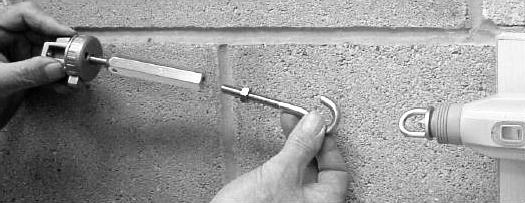
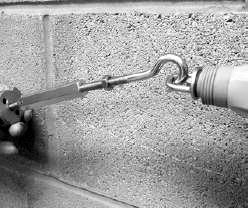
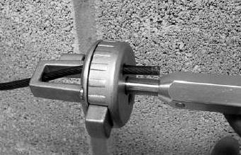
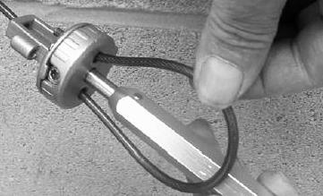
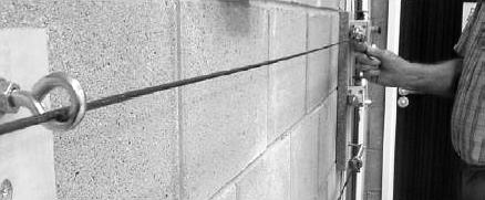
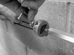
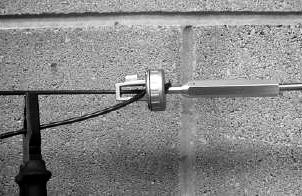
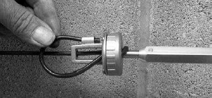
12 Installation of the wire When setting up an Emergency stop grab wire system from ABB Jokab Safety it is recommended to do the tensioning of the wire by using of ABB Jokab Safety Tensioner / Gripper accessory. The installation of the tensioner accessory reduces the installation time. The eyehook, tensioner thimble and the wire strength gripper are in one assembly which enables rapid connection to the switch eyebolts and fast and accurate tensioning of the wire. Thanks to the switch viewing window, systems can be accurately and quickly tensioned. The double clamp mechanism prevents wire slippage. The end of the safety wire is fed through a central hole in a cone shaped guide which protrudes from the main housing. After being fed through the guide hole, the wire enters the main housing by going through a feed hole and then is looped back through 180 degrees and is fed through a second feed hole on the opposite side of the mechanism. The wire is then pulled for maximum tension and is locked in position by a locking bar inside the main housing which is moved by turning an Allen type locking bolt. Because of the added friction on the eyebolts and wire when navigating corners, a corner pulley can be used to navigate inside or outside corners without causing damage to the wire. 1. Tension to mid position as indicated by the green arrows in the viewing window of each switch 2. The tensioner thimble allows immediate accurate and final tensioning of the wire, whilst viewing the tension marker through the viewing window on the switch 3. For systems up to 50 meter Quick Link termination is provided for easy connection to either a Safety spring or Switch eyebolt. (Note for systems above 50 meter a Tensioner / Gripper is required each side). Outside corners Outside corners Inside corners Examples of using the corner pulley 1) Machine 2TLC172248M0201, rev. A 12
13 Tensioner/Gripper TLC172248M0201, rev. A 13


14 TLC172248M0201, rev. A 14
15 Maintenance Every week: Check correct operation of system at locations along all coverage length and also the switch latching mechanism. Check for nominal tension setting, re-tension wire if necessary. Every 6 months: Isolate power and remove cover. Check screw terminal tightness and check for signs of moisture ingress. Warning! The safety functions and the mechanics shall be tested regularly. Warning! In case of breakdown or damage to the product, contact the nearest ABB/Jokab Safety Service Office or reseller. Do not try to repair the product yourself since it may accidentally cause permanent damage to the product, impairing the safety of the device which in turn could lead to serious injury to personnel. Caution! ABB/Jokab Safety will not accept responsibility for failure of the switch functions if the installation and maintenance requirements shown in this sheet are not implemented. These requirements form part of the product warranty. 2TLC172248M0201, rev. A 15
16 5 Application example 2TLC172248M0201, rev. A 16
17 6 Model overview Type Article number Description LineStrong1 2TLA050200R0030 2NC/2NO, M20 LineStrong2 2TLA050202R0332 2NC/2NO, M20, E-Stop, LED LineStrong2Z 2TLA050202R0322 2NC/2NO, M20, E-Stop, LED, stainless steel LineStrong2ZX 2TLA050202R7125 2NC, 3m cable, E-Stop, Stainless steel, Explosion proof LineStrong3L 2TLA050206R0332 4NC/2NO, M20, E-Stop, LED, left LineStrong3R 2TLA050208R0332 4NC/2NO, M20, E-Stop, LED, right LineStrong3LZ 2TLA050206R0322 4NC/2NO, M20, E-Stop, LED, left, stainless steel LineStrong3RZ 2TLA05008R0322 4NC/2NO, M20, E-Stop, LED, right, stainless steel LineStrong3LZX 2TLA050204R7125 2NC/2NO, 3m cable, E-Stop, Stainless steel, Explosion proof LineStrong3RZX 2TLA050206R7125 2NC/2NO, 3m cable, E-Stop, Stainless steel, Explosion proof LineStrong3D 2TLA050204R0332 4NC/2NO, M20, E-Stop, LED, double LineStrong3DZ 2TLA050204R0322 4NC/2NO, M20, E-Stop, LED, double, stainless steel LineStrong3DZX 2TLA050208R7125 2NC/2NO, 3m cable, E-stop, Stainless steel, Explosion proof Dimensions LineStrong1 2 Mounting Holes Clearance for M5 Screws LineStrong2 / LineStrong2Z(X) 4 Mounting Holes for M5 screws 2TLC172248M0201, rev. A 17
18 LineStrong 3L/R and LineStrong3LZ(X)/3RZ(X) LineStrong3D and LineStrong3DZ(X) NB! All measurements are in mm 2TLC172248M0201, rev. A 18
 Wire Tensioner:")


19 Accessories Type Article number Description Galvanized wire pull kits: 10 m wire kit 20 m wire kit 80 m wire kit 100 m wire kit Stainless steel wire pull kits: 50 m wire kit 100 m wire kit Wire only: 10 m wire 80 m wire 100 m wire 1 m wire (order by length) Wire Tensioner: Wire Tensioner, stainless steel Wire Tensioner, galvanized Corner pulley: Corner pulley, stainless steel Corner pulley, galvanized Eyebolt: Eyebolt, M8 x 1.25, stainless steel Eyebolt, M8 x 1.25, galvanized General wire pull accessories Safety spring, 220 mm long, stainless steel Screw driver, Anti-Tamper, Torx T20 M20 x 1.5 gland M20 x 1.5 conduit plug LED Green/Red 24VDC 2TLA050210R0130 2TLA050210R0330 2TLA050210R0630 2TLA050210R0730 2TLA050210R0520 2TLA050210R0720 2TLA050210R2120 2TLA050210R2520 2TLA050210R2620 2TLA020034R0500 2TLA050210R4020 2TLA050210R4030 2TLA050210R6020 2TLA050210R6030 2TLA050210R8020 2TLA050210R8030 2TLA050211R0004 2TLA050211R0006 2TLA050040R0002 2TLA050040R0004 2TLA050211R0001 Wire pull kit includes: Wire Eyebolts Tensioner / Gripper Allan key 2TLC172248M0201, rev. A 19
20 7 Technical data LineStrong1 Manufacturer Address Electrical characteristics Contact type Contact material Termination Utilisation category Thermal current (lth) Rated insulation/withstand voltages Short circuit overload protection General Wire span Wire tension devise Wire type Torque settings Tension force (typical mid setting) Tension operating force (wire pulled) Vibration resistance Shock resistance Conduit entries Enclosure classification Operating temperature Enclosure material/cover Mounting position Mounting bolts Weight (approx.) ABB AB / JOKAB SAFETY Varlabergsvägen 11 SE Kungsbacka Sweden IEC/EN double break Typ Zb Silver Clamp up to 2.5 mm 2 conductors AC15 A300 3A 240VAC 3A/120VAC 6A/24VDC 2.5A inductive 10 A 500VAC / 2500VAC Fuse externally 10 A (FF) Up to 50 m ABB Jokab Safety Wire Tensioner PVC sheath steel wire 4.0 mm outside diameter Mounting M5 4.0Nm Lid T20 Torx M4 1.5Nm Terminals 1.0Nm 130 N < 125N < 300 mm deflection Hz 0.35 mm 15 g 11 ms 3 x M20 IP67-25 C to +80 C Die cast painted yellow Any 4 x M kg 2TLC172248M0201, rev. A 20
21 Safety-related characteristic data and Conformity Conformity European Machinery Directive 2006/42/EC EN ISO 12100:2010, EN ISO 13850:2008, EN :2006+A1:2009 EN :2007+A1:2011, EN :2004+A1:2009, EN :1997+A1:2005 EN ISO Up to PL e, Cat. 4 depending upon system architecture EN Up to SIL3 depending upon system architecture Safety data Mechanical reliability B 10d PFH D Proof test interval (life) MTTF d Certifications Information with regard to UL x 10 6 operations at 100mA load <1.0x years 214 years (8 cycles per hour/24 hours per day/365 days) TÜV, culus Use 12AWG copper conductors only Electrical Rating: A300 48W5 Type 1 Enclosure Max. Switching Current / Volt / Amp: 120V 6A (720VA break) PF 0.38, 240V 3A (720VA break) PF 0.38 LineStrong2 series Manufacturer Address Electrical characteristics Contact type Contact material Termination Utilisation category Thermal current (lth) Rated insulation/withstand voltages Short circuit overload protection Explosion Proof version (X) Classification Rated Voltage Rated Current General Wire span LineStrong2 LineStrong2Z(X) Wire tension devise Wire type Torque settings Tension force (typical mid setting) Tension operating force (wire pulled) ABB AB / JOKAB SAFETY Varlabergsvägen 11 SE Kungsbacka Sweden IEC/EN double break Typ Zb Silver Clamp up to 2.5 mm 2 conductors AC15 A300 3A 240VAC 3A/120VAC 6A/24VDC 2.5A inductive 10 A 500VAC / 2500VAC Fuse externally 10 A (FF) Ex d IIC T6 (-20 C Ta +60 C) Gb Ex tb IIIC T85 C (-20 C Ta +60 C) Db 250V AC/DC 2 pole 4A 4 pole 2.5A Up to 80 m Up to 100 m ABB Jokab Safety Wire Tensioner PVC sheath steel wire 4.0 mm outside diameter Mounting M5 4.0Nm Lid T20 Torx M4 1.5Nm Terminals 1.0Nm 130 N < 125N < 300 mm deflection 2TLC172248M0201, rev. A 21
22 Vibration resistance Shock resistance Conduit entries Enclosure classification LineStrong2 LineStrong2Z(X) Operating temperature LineStrong2 LineStrong2Z(X) Enclosure material/cover LineStrong2 LineStrong2Z Mounting position Mounting bolts Weight (approx.) LineStrong2 LineStrong2Z(X) Hz 0.35 mm 15 g 11 ms 3 x M20 IP67 IP69K -25 C to +80 C -25 C to +80 C (100 C cleaning) Die cast painted yellow Stainless steel 316 Any 4 x M kg kg Safety-related characteristic data and Conformity Conformity EN ISO EN Safety data Mechanical reliability B 10d PFH D Proof test interval (life) MTTF d Certifications Information with regard to UL 508 European Machinery Directive 2006/42/EC EN ISO 12100:2010, EN ISO 13850:2008, EN :2006+A1:2009 EN :2007+A1:2011, EN :2004+A1:2009, EN :1997+A1:2005 Up to PL e, Cat. 4 depending upon system architecture Up to SIL3 depending upon system architecture 1.5 x 10 6 operations at 100mA load <1.0x years 214 years (8 cycles per hour/24 hours per day/365 days) TÜV, culus Use 12AWG copper conductors only Electrical Rating: A300 48W5 Type 1 Enclosure Max. Switching Current / Volt / Amp: 120V 6A (720VA break) PF 0.38, 240V 3A (720VA break) PF TLC172248M0201, rev. A 22
23 LineStrong3 series Manufacturer Address Electrical characteristics Contact type Contact material Termination Utilisation category Thermal current (lth) Rated insulation/withstand voltages Short circuit overload protection Explosion Proof version (X) Classification Rated Voltage Rated Current General Wire span LineStrong3L/R/LZ(X)/RZ(X) LineStrong3D/DZ(X) Wire tension devise Wire type Torque settings Tension force (typical mid setting) Tension operating force (wire pulled) Vibration resistance Shock resistance Conduit entries Enclosure classification LineStrong3D/L/R LineStrong3LZ(X)/RZ(X)/DZ(X) Operating temperature LineStrong3D/L/R LineStrong3LZ(X)/RZ(X)/DZ(X) Enclosure material/cover LineStrong3D/L/R LineStrong3LZ(X)/RZ(X)/DZ(X) Mounting position Mounting bolts Weight (approx.) LineStrong3D LineStrong3DZ(X) LineStrong3L/R LineStrong3LZ(X)/RZ(X) ABB AB / JOKAB SAFETY Varlabergsvägen 11 SE Kungsbacka Sweden IEC/EN double break Typ Zb Silver Clamp up to 2.5 mm 2 conductors AC15 A300 3A 240VAC 3A/120VAC 6A/24VDC 2.5A inductive 10 A 500VAC / 2500VAC Fuse externally 10 A (FF) Ex d IIC T6 (-20 C Ta +60 C) Gb Ex tb IIIC T85 C (-20 C Ta +60 C) Db 250V AC/DC 2 pole 4A 4 pole 2.5A Up to 125 m Up to 250 m ABB Jokab Safety Wire Tensioner PVC sheath steel wire 4.0 mm outside diameter Mounting M5 4.0Nm Lid T20 Torx M4 1.5Nm Terminals 1.0Nm 130 N < 125N < 300 mm deflection Hz 0.35 mm 15 g 11 ms 4 x M20 IP67 IP69K -25 C to +80 C -25 C to +80 C (100 C cleaning) Die cast painted yellow Stainless steel 316 Any 4 x M kg kg kg kg 2TLC172248M0201, rev. A 23
24 Safety-related characteristic data and Conformity Conformity European Machinery Directive 2006/42/EC EN ISO 12100:2010, EN ISO 13850:2008, EN :2006+A1:2009 EN :2007+A1:2011, EN :2004+A1:2009, EN :1997+A1:2005 EN ISO Up to PL e, Cat. 4 depending upon system architecture EN Up to SIL3 depending upon system architecture Safety data Mechanical reliability B 10d PFH D Proof test interval (life) MTTF d Certifications Information with regard to UL x 10 6 operations at 100mA load <1.0x years 214 years (8 cycles per hour/24 hours per day/365 days) TÜV, culus Use 12AWG copper conductors only Electrical Rating: A300 48W5 Type 1 Enclosure Max. Switching Current / Volt / Amp: 120V 6A (720VA break) PF 0.38, 240V 3A (720VA break) PF 0.38 The Jokab Safety branded product with articlenumber beginning with 2TLJ is fully compatible with the ABB branded product with articlenumber beginning with 2TLA. 2TLC172248M0201, rev. A 24
25 8 EC Declaration of conformity 2TLC172248M0201, rev. A 25
26 ABB AB / JOKAB SAFETY Varlabergsvägen 11, SE Kungsbacka, Sweden 2TLC172248M0201, rev. A 26
EStrong-series Emergency Stop
 Original instructions EStrong-series Emergency Stop ABB AB / Jokab Safety Varlabergsvägen 11, SE-434 39 Kungsbacka, Sweden www.abb.com/jokabsafety Read and understand this document Please read and understand
Sense7-series Non-contact coded safety switch
 Original instructions Sense7-series Non-contact coded safety switch ABB AB / Jokab Safety Varlabergsvägen 11, SE-434 39 Kungsbacka, Sweden www.abb.com/jokabsafety Read and understand this document Please
Tina 11A Connection block
 Original instructions Tina 11A Connection block ABB Jokab Safety Varlabergsvägen 11, SE-434 39 Kungsbacka, Sweden www.abb.com/jokabsafety Read and understand this document Please read and understand this
MKey9-series Safety Interlock Switch with Guard Locking
 Original instructions MKey9-series Safety Interlock Switch with Guard Locking ABB AB / Jokab Safety Varlabergsvägen 11, SE-434 39 Kungsbacka, Sweden www.abb.com/jokabsafety Read and understand this document
Smile 41 Push-button box with/without emergency stop
 Original instructions Smile 41 Push-button box with/without emergency stop ABB Jokab Safety Varlabergsvägen 11, 434 39 Kungsbacka www.abb.com/jokabsafety Read and understand this document Please read and
Tina 4A Connection block
 Original instructions Tina 4A Connection block Instructions valid for versions of the product from ver. H ABB Jokab Safety Varlabergsvägen 11, SE-434 39 Kungsbacka, Sweden www.abb.com/jokabsafety Read
Tina 10A/B/C Adaptor unit
 Original instructions Tina 10A/B/C Adaptor unit ABB Jokab Safety Varlabergsvägen 11, SE-434 39 Kungsbacka, Sweden www.abb.com/jokabsafety Read and understand this document Please read and understand this
FMC-1/2 Tina Muting unit
 Original instructions FMC-1/2 Tina Muting unit ABB Jokab Safety Varlabergsvägen 11, SE-434 39 Kungsbacka, Sweden www.abb.com/jokabsafety Read and understand this document Please read and understand this
Smile 11 RA/-B Smile 12 RF/-G Reset button
 Original Instructions Smile 11 RA/-B Smile 12 RF/-G Reset button ABB Jokab Safety Varlabergsvägen 11, SE-434 39 Kungsbacka, Sweden www.abb.com/jokabsafety Read and understand this User Manual Please read
Please note! This model of Eden is obsolete and has been replaced by Eden DYN. Original instructions Eden Non-contact safety sensor
 Original instructions Eden Non-contact safety sensor ABB Jokab Safety Varlabergsvägen 11, SE-434 39 Kungsbacka, Sweden www.abb.com/jokabsafety Read and understand this document Please read and understand
Safety Switches Machine Safety
 Safety Switches Machine Safety We develop products and solutions for machine safety The fact that the leading power and automation technology company, ABB, and a leader in machine safety, Jokab Safety,
Eden AS-i Proximity safety sensor
 Original instructions Eden AS-i Proximity safety sensor ABB Jokab Safety Varlabergsvägen 11, SE-434 39 Kungsbacka, Sweden www.abb.com/jokabsafety Read and understand this document Please read and understand
SAFETY PRODUCTS. ASK-Series Safety Mat Product Manual
 SAFETY PRODUCTS ASK-Series Safety Mat Product Manual 2TLC010047M0201_D ORIGINAL INSTRUCTIONS Read and understand this document Please read and understand this document before using the products. Please
Knox Safety and process lock
 Original instructions Knox Safety and process lock ABB Jokab Safety Varlabergsvägen 11, SE-434 39, Sweden www.abb.com/jokabsafety Read and understand this document Please read and understand this document
ZB0050 / ZB0051 ZB0070 / ZB0071
 Operating instructions Safety Rope Emergency Stop Switches UK ZB0050 / ZB0051 ZB0070 / ZB0071 7390877 / 02 08/2013 Contents 1 Safety instructions...3 2 Installation / set-up...4 2.1 Applications...4 2.2
SAFET Y PRODUCTS. TT-Series Safety Edge Product Manual
 SAFET Y PRODUCTS TT-Series Safety Edge Product Manual 2TLC010046M0201_B ORIGINAL INSTRUCTION S Read and understand this document Please read and understand this document before using the products. Please
Original instructions Eden OSSD Coded non-contact safety sensor
 Original instructions Eden OSSD Coded non-contact safety sensor ABB Jokab Safety Varlabergsvägen 11, SE-434 39 Kungsbacka, Sweden www.abb.com/jokabsafety Read and understand this document Please read and
Operation Key D4BS - K Head Mounting Direction F: Four mounting directions possible (front-side mounting at shipping)
") Safety-door Switch D4BS The Special Activates a Direct Opening Mechanism to Open the Contacts and Shut Off Control Circuits when Protective Doors Are Opened on Machine Tools or Other Equipment CSM_D4BS_DS_E_6_1
Safety-door Switch D4BS The Special Activates a Direct Opening Mechanism to Open the Contacts and Shut Off Control Circuits when Protective Doors Are Opened on Machine Tools or Other Equipment CSM_D4BS_DS_E_6_1
2NC (slow-action) Direct. Model. opening
 Direct. Model. opening") Small Safety Limit Switch CSM DS_E_3_1 Smallest Class of Safety Limit Switches in the World Note: Contact your sales representative for details on models with safety standard certification. The world's
Small Safety Limit Switch CSM DS_E_3_1 Smallest Class of Safety Limit Switches in the World Note: Contact your sales representative for details on models with safety standard certification. The world's
Eden OSSD Coded non-contact safety sensor
 Original instructions Eden OSSD Coded non-contact safety sensor ABB Jokab Safety Varlabergsvägen 11, SE-434 39 Kungsbacka, Sweden www.abb.com/jokabsafety Read and understand this document Please read and
D4BS CSM_D4BS_DS_E_8_4
 Safety-door Switch CSM DS_E_8_4 The Special Activates a Direct Opening Mechanism to Open the Contacts and Shut Off Control Circuits when Protective Doors Are Opened on Machine Tools or Other Equipment
F3S-TGR-KHL1/-KHL3/-KHL3R
 Safety guard-lock door switches with full stainless steel body F3S-TGR-KHL1/-KHL3/-KHL3R The F3S-TGR-KHL3 safety-door switch keeps medium to large guard doors closed until hazards have been removed. It
D4GS-N CSM_D4GS-N_DS_E_7_2
 Slim Safety Door Switch D4GS-N CSM_D4GS-N_DS_E_7_2 Slim Safety Door Switches with IP67 Rating Slim design with a width of only 17 mm (three-contact models). Reversible design allowing either front or rear
E2E2. Proximity Sensor with a Long Screw Length. Long-barrel Inductive Proximity Sensor. Ordering Information. Sensors DC 2-Wire Models
 Long-barrel Inductive Proximity Sensor EE CSM_EE_DS_E Proximity Sensor with a Long Screw Length Increased tightening strength. Cable protectors provided as a standard feature. Increased indicator visibility.
D4NS. Safety-door Switch. Multi-contact, Labor-saving, Environment-friendly, Next-generation Safety-door Switch. Model Number Structure
 Safety-door Switch D4NS CSM_D4NS_DS_E_5_2 Multi-contact, Labor-saving, Environment-friendly, Next-generation Safety-door Switch Lineup includes three contact models with 2NC/1NO and 3NC contact forms and
Multiple Limit Switch
 Multiple Limit Switch CSM DS_E_1_1 A New Monoblock Multiple Limit Switch Incorporating a ead Box with a Tough ead and Ensuring igh Sealing Performance and a Mechanical Durability of 5,000,000 Operations
D4BL. Guard Lock Safety-door Switch
 Guard Lock Safety-door Switch D4BL CSM_D4BL_DS_E_5_1 Release Protective Cover Locks Using Controller Signals or Pushbutton Switches after the Cutting Tool Stops Moving Due to Inertia A mechanical lock
0.5 s to 30 h (30 s, 3 min, 30 min, 3 h, 30 h)
") Mechatronic Analog Timer H3AM Please read and understand this catalog before purchasing the products. Please consult your OMRON representative if you have any questions or comments. Refer to Warranty and
Mechatronic Analog Timer H3AM Please read and understand this catalog before purchasing the products. Please consult your OMRON representative if you have any questions or comments. Refer to Warranty and
Safety Limit Switch
 Safety Limit Switch D4B-@N CSM_D4B-_N_DS_E_4_1 Snap-action contact with certified direct operation certification. Maintenance, seal, and resistance to shock increased and direct mechanism added. Three-conduit
F3S-TGR-KM15/-KM16/-KH16
 Safety door switches with partially or full stainless steel body F3S-TGR-KM1/-KM16/-KH16 This safety door switches use a stainless steel head or even a full stainless steel body to increase the robustness.
Safety stop buttons Smile, INCA and Compact
 Smile, INCA and are used to safely stop a certain part of a dangerous machine. ABB offers safety stop buttons to suit different needs of connection and communication. Models are available for e.g. external
M2S. Indicator Series with Square 40-mm Body. Indicator (Square) List of Models
 List of Models") Indicator (Square) CSM DS_E_3_2 Indicator Series with Square 40-mm Body Same type of Indicator as those in the A3S-series Pushbutton Switch Easy panel mounting from the front and simple lamp replacement
Indicator (Square) CSM DS_E_3_2 Indicator Series with Square 40-mm Body Same type of Indicator as those in the A3S-series Pushbutton Switch Easy panel mounting from the front and simple lamp replacement
Digital display Pressure range ON/OFF output Linear output Model
 Slim Digital Pressure Sensor E8CC with Built-in Microcomputer and Digital Display Withstands a pressure of 49 kpa and highly reliable. Incorporates a two-turn pressure adjuster ensuring easy pressure setting.
D4BL. Guard Lock Safety-door Switch. Die-cast aluminum body Key holding force of 700 N. Model Number Structure. Model Number Legend Switch D4BL - K
 Guard Lock Safety-door Switch D4BL CSM_D4BL_DS_E_10_1 Die-cast aluminum body Key holding force of 700 N Auxiliary release key ensures easy maintenance and unlocks the door in the case of a power failure.
Safety interlock switch MKey
 Safety interlock switch MKey MKey are mechanical safety switches used for monitoring doors and hatches. The switch is mounted on the frame and the actuator key on the moving part of the guard. All MKey
G3PE-Single-phase. Solid State Relays for Heaters
 Solid State Relays for Heaters Single-phase CSM_Single-phase_DS_E Compact, Slim-profile SSRs with Heat Sinks. s with No Zero Cross for a Wide Range of Applications. RoHS compliant. s also available with
IP69K Stainless Steel Safety Interlock Switches
 IP69K Stainless Steel Safety Interlock Switches Designed specifically for Food Processing, Packaging, Pharmaceutical and Petro-Chemical industries Suitable for CIP Cleaning Fully Stainless Steel IP69K
Safety rope switches with reset for emergency stop
 Safety rope switches with reset for emergency stop Selection diagram 8 8 83 ACTUATORS ACTUATORS CONTACT BLOCKS 18 9 21 1NO+ FP FD FL FC 22 33 34 LED signalling light CONDUIT ENTRIES For other available
D4NH. Safety-door Hinge Switch. Compact, Plastic-body Safety-door Hinge Switch Designed for Saving Space in Machines and Other Equipment
 Safety-door Hinge Switch CSM DS_E_4_1 Compact, Plastic-body Safety-door Hinge Switch Designed for Saving Space in Machines and Other Equipment Note: Contact your sales representative for details on models
A165S/W. Separate Construction with Cylindrical 16-dia. Body. Knob-type Selector Switch (Detachable) (Cylindrical 16-dia.
 (Cylindrical 16-dia.") Knob-type Selector Switch (Detachable) (Cylindrical 16-dia.) CSM_A165S_W_DS_E_4_1 Separate Construction with Cylindrical 16-dia. Body Same separate construction as the A16-series Pushbuttons with Miniature
Knob-type Selector Switch (Detachable) (Cylindrical 16-dia.) CSM_A165S_W_DS_E_4_1 Separate Construction with Cylindrical 16-dia. Body Same separate construction as the A16-series Pushbuttons with Miniature
A165E CSM_A165E_DS_E_11_2
 Emergency Stop Switch (16-dia.) CSM DS_E_11_2 Separate Construction with Minimal Depth Direct opening mechanism to open contacts in emergencies, such as when they are welded. Conforms to EN 6947-5-5. Includes
D4BL. Guard Lock Safety-door Switch
 Guard Lock Safety-door Switch D4BL CSM_D4BL_DS_E_7_1 Release Protective Cover Locks Using Controller Signals or Pushbutton Switches after the Cutting Tool Stops Moving Due to Inertia A mechanical lock
(3) Terminals. 00: AC connector. Comparison of New and Old Molded Terminal Models. Model Location of lead outlet
 Terminals. 00: AC connector. Comparison of New and Old Molded Terminal Models. Model Location of lead outlet") Small Sealed Switch D4E-N CSM_D4E-_N_DS_E_4_ Slim and Compact Switch with Better Seal and Ensuring Longer Service Life than D4E Flat springs with an improved lever ratio of the built-in switch ensure smooth
Small Sealed Switch D4E-N CSM_D4E-_N_DS_E_4_ Slim and Compact Switch with Better Seal and Ensuring Longer Service Life than D4E Flat springs with an improved lever ratio of the built-in switch ensure smooth
IDEM Solenoid Interlock Safety Switches
 KLP/KLM/KL3-SS Series Housing Solenoid locking, tongue (key) interlock operated Power to unlock 90 degree adjustable head One (KLP) or three (KLM, KL3-SS) 1/2 in. female NPT conduit opening 30mm mounting
2NC (slow-action) Direct. Model. opening
 Direct. Model. opening") Small Safety Limit Switch D4F CSM_D4F_DS_E_5_2 Smallest Class of Safety Limit Switches in the World Note: Contact your sales representative for details on models with safety standard certification. The
Small Safety Limit Switch D4F CSM_D4F_DS_E_5_2 Smallest Class of Safety Limit Switches in the World Note: Contact your sales representative for details on models with safety standard certification. The
Model Number Legend (Completely Assembled)... Shipped as a set which includes the Operation Unit, Lamp (lighted models only), and Switch. 4.
... Shipped as a set which includes the Operation Unit, Lamp (lighted models only), and Switch. 4.") Emergency Stop Switch (-dia./5-dia.) AE CSM_AE_DS_E_7_ Install in -dia. or 5-dia. Panel Cutout Direct opening mechanism to open the circuit when the contact welds. Safety lock mechanism prevents operating
Emergency Stop Switch (-dia./5-dia.) AE CSM_AE_DS_E_7_ Install in -dia. or 5-dia. Panel Cutout Direct opening mechanism to open the circuit when the contact welds. Safety lock mechanism prevents operating
Safety rope switch with reset for emergency stop
 Safety rope switch with reset for emergency stop Selection diagram 8 8 83 ACTUATORS ACTUATORS CONTACT BLOCKS 18 9 21 1NO+,, FP FD FL FC 22 33 34,, CONDUIT ENTRIES Threaded conduit entries (standard) With
Features. Emergency Stop Switch A165E. Separate Construction with Smallest Class of Depth in the World. Safety Lock Prevents Misuse
 Emergency Stop Switch Separate Construction with Smallest Class of Depth in the World Direct opening mechanism to open contacts in emergencies, such as when they are welded. Conforms to EN418. Includes
Operating Instructions
 Important Information: These instructions contain safety information, read and follow them carefully. Dialight will not accept any responsibility for injury, damage or loss which may occur due to incorrect
Model Number Structure
 Solid State Relays CSM OEE_DS_E_1_2 Extremely Thin Relays Integrated with Heat Sinks Downsizing achieved through optimum design of heat sink. Mounting possible via screws or via DIN track. Close mounting
A22LK CSM_A22LK_DS_E_6_2
 Guard Lock Safety Key CSM DS_E_6_2 The guard lock prevents accidental mode changes. for secure equipment activation during maintenance The guard lock of the Operation Unit prevents incorrect operation.
D4BL. Protective Doors Are Locked Until Machines Completely Stop Operating. Guard Lock Safety-door Switch. Model Number Structure.
 Guard Lock Safety-door Switch Protective Doors Are Locked Until Machines Completely Stop Operating A mechanical lock is applied automatically when the Operation Key is inserted. A high level of safety
CAUTION CM-SE CM-S21 CM-S41
 CAUTION Safety, Technology & Innovation CM Series Operating Instructions for, CM-S21,, CM-S11, CMS31 CM Series Safety System This information is designed to help suitably qualified personnel install and
Cable (Rope) Pull Switches Lifeline 4
 Pull Switches Lifeline 4") Emergency Stop Devices Description The cable/push button operated system can be installed along or around awkward machinery such as conveyors and provide a constant emergency stop access. The is the only
Emergency Stop Devices Description The cable/push button operated system can be installed along or around awkward machinery such as conveyors and provide a constant emergency stop access. The is the only
LK Position Switches TECHNICAL DATASHEET.
 LK Position Switches Technopolymer housing, one conduit entry Protection degree IP6 according to EN 60529 contact blocks available 46 actuators available Versions with stainless steel external parts Versions
DIN Track Terminal Blocks with Screw Terminals
 New Product DIN Track Terminal Blocks with Screw Terminals XW5T Global-standard DIN Terminal Blocks for Control Panels Wires held with screws. Compatible with a wide range of wire sizes with a nominal
Safety switches with solenoid and separate actuator
 Safety switches with solenoid and separate actuator These switches are used on machines where the hazardous conditions remain for a while, even after the machines have been switched off, for example because
Operating instructions Pull-wire emergency-stop switches EX-ZQ About this document. Content
 Pull-wire emergency-stop switches 1. bout this document Operating instructions.............pages 1 to 6 Original 1.1 Function This operating instructions manual provides all the information you need for
DIN Track Terminal Blocks with Screw Terminals XW5T
 New Product DIN Track Terminal Blocks with Screw Terminals XW5T Global-standard DIN Terminal Blocks for Control Panels Wires held with screws. Compatible with a wide range of wire sizes with a nominal
Safety Guard Switching Unit G9SX-GS
 Enabling Grip Switch CSM DS_E_5_1 Enabling Grip Switch with Distinct Feel for Three Easily Discernible Positions The difficult task of configuring safety circuits is now easily achieved by combining the
Operator Interface 4-1. General. Safety Switches. 4-Table of. Contents. Logic. Power. Operator Interface Table of Contents. 2-Opto-electronics
 Table of Contents Emergency Operator Interface Overview...4-2 LIfeline ope Tensioner System (LTS)...4-4 Lifeline 3...4-6 Lifeline 4...4-10 Lifeline 4 Stainless Steel...4-16 Enabling Switches GripSwitch...4-24
Ordering Information. Specifications. Motor Time Switch H2F-WM. Accessories (Order Separately) Time Specifications. Ratings
 Time Specifications. Ratings") Motor Time Switch H2F-WM CSM_H2F-WM_DS_E_2_1 Weekly ON/OFF Control in 1-h Increments The H2F-WM is a Compact Weekly Time Switch in a DIN -mm Body Equipped with Power Interruption Backup Providing Protection
Motor Time Switch H2F-WM CSM_H2F-WM_DS_E_2_1 Weekly ON/OFF Control in 1-h Increments The H2F-WM is a Compact Weekly Time Switch in a DIN -mm Body Equipped with Power Interruption Backup Providing Protection
RS-3 PRO RS-1007 PRO. CAT IV Analog Clamp meter Series. Users Manual. For detailed specifications and ordering info go to
 RS-3 PRO RS-1007 PRO CAT IV Analog Clamp meter Series Users Manual For detailed specifications and ordering info go to www.testequipmentdepot.com RS-3 PRO RS-1007 PRO CAT IV Analog Clampmeter Series English
DIN Track Terminal Blocks with Screw Terminals XW5T
 New Product DIN Track Terminal Blocks with Screw Terminals XW5T Global-standard DIN Terminal Blocks for Control Panels Wires held with screws. Compatible with a wide range of wire sizes from 0.14 to 185
J 6 Se r i e s. Pressure and Vacuum switches. features
 J 6 S er i es J 6 Se r i e s Pressure and Vacuum switches features Gasketed, Die Cast Aluminum Enclosure with Epoxy Coating SPDT Switch Output Adjustable Deadband Option Sealed, Isolated Metal Bellows
D4NH CSM_D4NH_DS_E_7_1
 Safety-door Hinge Switch D4NH CSM_D4NH_DS_E_7_1 Compact, Plastic-body Safety-door Hinge Switch Designed for Saving Space in Machines and Other Equipment Lineup includes three contact models with 2NC/1NO
MICRO SWITCH Solenoid Safety Interlock Switches GKL/R Series Issue 2. Datasheet
 MICRO SWITCH Solenoid Safety Interlock Switches GKL/R Series DESCRIPTION MICRO SWITCH GKL/R Series switches are a heavy-duty key operated solenoid safety interlock switch incorporating a key trapping mechanism.
D4BS. Safety-door Switch. Model Number Structure. Switch D4BS - S Operation Key D4BS - K. Ordering Information
 Safety-door Switch Safety-door Switch s Special Operation Key Directly Pulls Apart the Contacts from Each Other and Contributes to the Safety of the Production Site Conforms to EN (TÜV) standards corresponding
Operating Instructions
 Operating Instructions Pendant Light Fitting > Contents 1 Contents 1 Contents...2 2 General Information...2 3 General Safety Instructions...3 4 Conformity to Standards...3 5 Intended Field of Application...3
Position switches FC series
 A Position switches FC series Selection diagram 0 08 8 9 0 0 0 Ø 8 mm Ø, mm external rubber stainless steel stainless steel fiber glass rod gasket sphere sphere 6 adjustable lever safety adjustable lever
Safety Limit Switch
 Safety Limit Switch D4B-@N CSM_D4B-_N_DS_E_5_1 Snap-action contact with certified direct operation certification. Maintenance, seal, and resistance to shock increased and direct mechanism added. Three-conduit
Safety-door Switch. Ordering Information
 Safety-door Switch Safety-door Switch s Special Operation Key Positively Pulls Apart the Contacts from Each Other and Contributes to the Safety of the Production Site Special Operation Key prevents mis-operation.
Position switches FR series
 Position switches FR series Selection diagram 0 A 08 0-0 A A 0 A external rubber gasket external rubber gasket for electrical panels external rubber gasket external rubber gasket external rubber gasket
10 S e r i e s PRESSURE SWITCH. features
 10 S er i es 10 S e r i e s PRESSURE SWITCH features Tamper-Resistant Field Adjustment Adjustable Ranges from 4 to 7500 PSI (0,3 to 517,1 Bar) Choice of 7 Electrical Terminations 1-1/4" Diameter Height
Universal Gate Box with Safety Interlocking TYPE: UGB-KLT FEATURES & APPLICATION:
 SECTION 6 Universal Gate Box with Safety Interlocking TYPE: UGB-KLT FEATURES & APPLICATION: 70 Application: IDEM Universal Gate Boxes (UGB-KLT) provide high level RFID coded interlocking and machine control
Leading the way in hazardous areas Features EATON
 .2 Ex-escape sign luminaires EXIT for Zone 1 and Zone 21 / Exit 2 for Zone 2 and Zone 22 Moulded plastic version with LED-technique Leading the way in hazardous areas The EXIT series of explosionprotected
LED Signal Towers. Pre-assembled and pre-cabled in different aperture to highlight the processes. Features/Unique selling proposition
 Pre-assembled and pre-cabled in different aperture to highlight the processes LED Signal Towers Modular and monolithic design are available. Patlite s extensive product range cover highly advanced LED
Position switches FR series
 Position switches FR series Selection diagram 01 A1 08 14 01-7 0 A 05 A5 external rubber gasket external rubber gasket for electrical panels external rubber gasket external rubber gasket 0 1 5 34 50 33
Safety switches for hinges
 Safety switches for hinges Selection diagram ACTUATORS L L6 L9 L16 FR FM FX FZ FK CONTACT BLOCKS 6 7 9 14 18 snap action 1NO+1N, make before break, shifted, close 21 4 66 NC 2NO+ 1NO+ CONDUIT ENTRIES Threaded
Universal Gate Box with Safety Interlocking TYPE: UGB-KLT FEATURES & APPLICATION:
 SECTION 6 Universal Gate Box with Safety Interlocking TYPE: UGB-KLT FEATURES & APPLICATION: 78 Application: IDEM Universal Gate Boxes (UGB-KLT) provide high level RFID coded interlocking and machine control
Applicable output load (See note 2.) Photocoupler Yes Yes 40 A at 110 to 220 VAC 5 to 24 VDC G3NB-240B 5 to 24 VDC G3NB-240B-UTU 5 to 24 VDC
 Photocoupler Yes Yes 40 A at 110 to 220 VAC 5 to 24 VDC G3NB-240B 5 to 24 VDC G3NB-240B-UTU 5 to 24 VDC") Solid State Relays G3NB with 40-A output at a reasonable price. Switches 9 A without a heat sink. Zero cross function enables less noise operation. Built-in varistor effectively absorbs external surges.
Solid State Relays G3NB with 40-A output at a reasonable price. Switches 9 A without a heat sink. Zero cross function enables less noise operation. Built-in varistor effectively absorbs external surges.
Safety rope switch without reset for simple stop
 afety rope switch without reset for simple stop election diagram FP 4-M2 FD 4-M2 FL 4-M2 FR 4-M2 FM 4-M2 FX 4-M2 FZ 4-M2 ACTUATOR 9 ACTUATOR 9 0 CONTACT BLOCK 1 9 21 1NO+ FP FD FL FC 33 34 CONDUIT ENTRIE
Position switches FD series
 Position switches FD series Selection diagram 01 08 11 18 19 02 04 05 Ø 8 mm Ø, mm external rubber stainless steel stainless steel fibber glass rod gasket sphere sphere 51 52 5 56 41 42 adjustable lever
XW2R-COM. Common Terminals X W 2R - P D - COM. Space-saving and less wiring work of power supply wiring are achieved. Application Example
 Common Terminals XW2R-COM CSM_XW2R-P_M_B-COM_DS_E Space-saving and less wiring work of power supply wiring are achieved. Common wiring is already wired on the PCB, transition wiring is unnecessary. Wiring
D4B- N. Safety Interlock Switches. Safety Limit Switch. Specifications. Standards and EC Directives. Certified Standard Ratings D4BN
 Safety Interlock Switches D4B- N D4BN Safety Limit Switch Snap-action contact with certified direct operation. mechanism (NC contacts only) added to enable contacts when faults occur, such as fused contacts.
Safety switches with solenoid and separate actuator
 Safety switches with solenoid and separate actuator These switches are used on machines where the hazardous conditions remain for a while, even after the machines have been switched off, for example because
NEO-DYN MODEL 100P ENCLOSURE 7 ADJUSTABLE EXPLOSION-PROOF PRESSURE SWITCH
 NEO-DYN MODEL 100P ENCLOSURE 7 ADJUSTABLE EXPLOSION-PROOF PRESSURE SWITCH INSTALLATION AND OPERATION MANUAL PN 610-0006 Rev E WARNING CAUTION SPECIAL CONDITIONS FOR SAFE USE NOTE Manual No. 610-0006 Rev
model ps600 Address all communications and shipments to: FEDERAL SIGNAL CORPORATION
 MODEL: PS600 HZ: 60 A model ps600 installation and service manual for federal model ps600 FEDERAL SIGNAL CORPORATION POWER SUPPLY VOLTS: SERIES: 120VAC FEDERAL SIGNAL CORPORATION UNIVERSITY PARK, IL. U.S.A.
Operating instructions Solenoid interlock EX-AZM About this document. Content
 EX-AZM 161 1. About this document Operating instructions.............pages 1 to 6 Translation of the original operating instructions 1.1 Function This operating instructions manual provides all the information
Technical Data. Dimensions
 Model Number Features 40 mm flush 4-wire DC ATEX-approval for zone 2 and zone 22 S Technical Data specifications Switching element function PNP NO/NC Rated operating distance s n 40 mm Installation flush
M-0. M-0... series control, monitoring and signalling devices. Ex e
 M-0 The new Cortem M-0 series control, monitoring and signalling devices are installed as external accessories on '' enclosures and boards used in any industrial environment where an explosive atmosphere
Ratings 1 A at 125 VAC 1 A at 30 VDC LED indicator Without indicator With indicator Without indicator With indicator Actuator
 Miniature Limit Switch CSM DS_E_3_3 Many Models Including Roller Lever Switches are Only -mm Thick with Connector New center roller lever models that enable ganged mounting of up to 6 Switches. Cable connectors
PRODUCT SPECIFICATION. Foot Switches. Series.
 PRODUCT SPECIFICATION Foot 46 Series www.wernerelektrik.com Foot Switch Structures...1 Technical Data...2 Model Number Structure - Foot...3 Dimensions...4 Precautions... Foot WERNERS are Rigorous and tough.
Operating instructions Solenoid interlock TKM/TKF. 1. About this document. Content
 1. About this document Operating instructions.............pages 1 to 6 Original 1.1 Function This operating instructions manual provides all the information you need for the mounting, set-up and commissioning
Command devices Pull-wire emergency stop switches One-side operation ZS 71 range Schmersal Industrial Switchgear.
 .1.1.1 One-side operation ZS 71 range 40 30 ø10 10 22 6 8 53,5 18 24 105 33 56 Pg 13,5 52 17,5 42 15 Features To EN 418 Metal enclosure 2 contacts Small body 2 cable entries Various spring force variants
S8JX-N/S8JX-G Series Replacement Brackets
 Original model mounting method Bottom mounting Front mounting Side mounting Original model: S8JX-N/S8JX-G Replacement model: S8FS-G Replacement bracket Model scheduled to be discontinued Recommended replacement
OPERATING INSTRUCTIONS
 OPERATING INSTRUCTIONS RTECK terminal boxes RTKB series IEC Ex EX010 TECHNICAL FILES CONTENTS: 1) Contents 2) General information 3) Safety information 4) Conformity to standards 5) Function 6) Technical
D4DL. Guard Lock Safety-door Switch. Model Number Structure
 Guard Lock Safety-door Switch Two new types added to series: Mechanical-lock models that lock automatically when the Operation Key is inserted, and solenoid-lock models that lock when voltage is applied
ILED Dorado. User Manual
 10NM U-code Medium Intensity Obstruction Light Helideck Status Light 15NM U-code Contents 1. Safety... 3 2. Warranty... 3 2.1 General... 3 2.2 Life span... 3 3. Type plate... 4 4. Product Description...
FL series position switches
 FL series position switches Selection diagram 0 08 0 9 0 0 0 Ball Ø. External rubber Ball Ø 8 mm, mm, stainless Glass fibre rod gasket stainless steel steel Adjustable lever Adjustable safety lever Bistable