Installing the RT-50A Rain Tracker on a Toyota Prius 2010 (v3 European model)
|
|
|
- Clement Arnold
- 5 years ago
- Views:
Transcription
1 Installing the RT-50A Rain Tracker on a Toyota Prius 2010 (v3 European model) Introduction This document describes how to install and customize the RT-50A Rain Tracker on a Toyota Prius 2010 (v3) not provided of automatic wipes. RT-50A, produced by Hydreon/Xenso is a hands-free rain and light sensing retrofit cruise control, automatically driving windshield wipers and headlights. Installing it on a Prius provides both automatic wipers and automatic headlights within a single control module. How the RT50A Rain Tracker works The RT50 Rain Tracker system is composed of three elements: An intelligent optical sensor snapped into a coupler that bonds permanently to the windshield. A relay interface unit. Wiring components. The intelligent optical sensor coupled on the inside surface of windshield includes two pairs of infrared light emitters/detectors and a PIC microcontroller based logical unit; it is responsible of: discerning sunlight from night time, determining rain, driving intermittence of wipers at slow speed and switching wipers to high speed. The sensor cable connects the relay interface unit through three wires: +12V power supply to the B+ car ignition (a 5V linear voltage regulator is included inside the sensor) output ground The output pin carries discrete analogical voltages; values are the following: 0 V (constant value) = no rain, sunlight 1 V (constant value) = no rain, night time 1 V / 2 V intermittent pulses with variable frequency = slow drizzle 2 V (constant value) = slow rain 4 V (constant value) = fast rain The relay interface unit is an analog device including four separate elements: The fast mode relay (pins 9 and 10), driven by a 4V comparator (and powered by the MODE READER pin 3). The slow mode relay (pins 6, 7 and 8), driven by a 2V comparator (and also powered by the MODE READER pin 3). The cam feedback, which drives the slow mode relay through a +12V positive input (the brown wire) in parallel with the slow mode rain element. The headlamp relay (yellow and green/yellow wires), driven by a 1V comparator powered by the B+ (+12V ignition). By consequence of this, when the fast mode relay is active, also the slow mode relay is switched on. Besides, when fast mode or slow mode wipes are active, also the headlamp relay is switched on. Notice also that the headlamp control is always active, even when the MODE input is not connected. This means that it can be independently managed by a separate activation switch. 1/15
.")
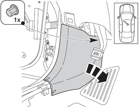
2 Connections in summary The diagram that can be found at is a valid reference for the installation. This means that information valid for a TOYOTA PRIUS can be generally extended to the Prius 2010 (that is not directly reported on Rain Tracker s site at the moment). In summary: The Rain Tracker wiper cruise control works in parallel with the existing wiper system, so the existing manual control modes are not affected. Wire colors of the wipers stalk switch in the steering column are red for slow, white for fast, white/black for ground, brown for +12V ignition; notice that the Rain Tracker documentation reports light green for +12V ignition; maybe that refers to previous Prius modes; Prius v has a brown wire. The red wire related to the slow mode winding needs to be cut inside the steering column as described in Rain Tracker documentation. Diode WHT/YEL (pins 5-4) is needed. Cam feedback is not needed. The headlamps control perfectly works and is very easy to install. It does not need any external relay, because the Prius headlights stalk switch already controls the headlight relay through its electronic control unit. Switching on parking lights and headlights can be simply obtained by grounding pin 20 blue of the stalk switch connector on the steering column. As this is a gate control, a very limited current flows. Detailed mounting To remove the bottom portion of the steering wheel column cover, perform the following actions. Disconnect battery terminal following the instructions in the owner's manual. Check the following pictures to open the steering wheel column cover: push the right side of the lower housing in to disengage the two claws. Do the same for the left side. 2/15


: ground Notice that, with the Prius European model, by connecting pin 20 to pin 12, headlights come always on, regardless the vehicle is powered")
 has the following useful pins: Thick 16AWG brown: 12V+ ignition Thick 16AWG red: slow wiping")
3 Rotate the steering wheel so that the top of the wheel is facing the drivers side door. You will see a small rectangular hole in the front of the lower housing. Find something that fits in it. Pull the cover towards the driver side while pushing inward the hole to release the claw: without pulling the cover, the disengaging operation will result difficult. Spin the wheel 180 degrees clockwise and repeat the claw disengagement for the right side. The cover will come right off, exposing the headlight wire harness and the wiper wire harness. These harnesses for ease of access can be removed by pushing on the little release lever on the plugs. Note that the wiper harness is actually constituted by two separate plugs. The connector on the left side of the steering column, below the left stalk switch (lights) is L47; useful pins are: Pin 20 (thin blue 24AWG): when connected to ground, it turns on tail lights + parking lights + headlights Pin 12 (thin green 24AWG): ground Notice that, with the Prius European model, by connecting pin 20 to pin 12, headlights come always on, regardless the vehicle is powered on or off. Current flowing between these two pins is very limited (few hundreds microamperes). The larger white connector on the right side of the steering column, below the right stalk switch (wipers) has the following useful pins: Thick 16AWG brown: 12V+ ignition Thick 16AWG red: slow wiping speed; this wire is grounded by the cam when the stalk switch is in its default position Thick 16AWG white: fast wiping speed Notice: do not short the red wire to the brown one when the wipers stalk switch is in its default position. 3/15

4 The other connector below the right stalk switch (wipers) has a white/black wire, which is an alternative ground than pin 12 of L47. The wires of the two wiper connectors can be better managed by removing the black tape joining them. The following picture shows the impacted connectors with related labels A, B, C, D and E. White-black Ground Green Interm. Brown - + IGN Red - Slow White - Fast A B Cut red wire +2 E C B D A C D E Connector labeled F is the blue one below the light stalk switch (see the following picture). Subsequently, the schematic diagram for interconnecting the RT-50A to the Prius 2010 v3 is reported. It is based on a two-key keyboard (only one key is included in the kit). A possible modification described afterwards introduces an additional key to enable the headlights come on automatically when the vehicle is on, regardless the rain or light mode. 4/15
5 Blue (pin 20) Headlights F F D +12V Ignition E B C A F Label Wire of RT-50A Wire of wipers connector Wire of headlamp connector A Black White-Black B Purple Red (connector side) C Blue Red (harness side) D Red, Yellow, Orange (and switch cable) Brown E Pink White F Yellow Blue (pin 20) 5/15
6 For the sake of clarity, the used labels are also reported in the standard RT-50A wiring diagram. B C A E D To perform tee connections to existing power wires, Toyota suggest the following. 6/15
 for E and D connections; all have been covered with heat-shrink tubing.")
7 Toyota uses single coated adhesive foam tape (not included in the kit). Pay attention to select an electrical tape resisting to high temperature. I used the following: two-screw terminal strips (chocolate blocks, not included in the kit) for E and D connections; all have been covered with heat-shrink tubing. Single screw terminals (not included in the kit) to wire together red, gray, yellow and orange cables to the one connected with the ignition wire through a two-screw terminal through a short thick cable. 7/15

8 No-strip tee splices for A and F connections Big lock-in crimp Lucar terminals (male/female) with full insulation shields (connectors and related insulators not included in the kit) for B and C connections The following picture shows the performed connections. Hole to host the relay interface Keyboard On the right side of the internal space below the steering wheel there is a deep hole where the control unit can be fastened in oblique position. Notice not to leave the small socket unconnected in case it is not used, as its pins can cause shorts. 8/15


9 Sensor and coupler can be installed as explained in the instructions. Please, follow the installation notes very carefully, cleaning the glass. The sensor can be installed just below the rear view mirror, within the area swept by the wipers, and out of the shadeband. 9/15

10 When calculating the space between sensor and mirror, consider also the length of the sensor socket. In the following picture, the sensor socket had to be twisted due to lack of space. It would be better to avoid this operation, even if not influencing at all the electric connections and not compromising so much its mechanical performance. Ignition based headlamps: a possible further mod If the driver wants to always keep the headlights on, regardless rain and light, a useful modification can be implemented, effective with European Prius models not equipped with stalk switch AUTO position, where the parking lights will not turn off automatically when powering off a car. More precisely on these versions, after turning the stalk switch to the headlights position, if the car is started and then switched off, the tail lights and the parking lights remain switched on while the headlights come automatically off (besides, when opening the door, a buzzer warns to release the stalk switch to its off position before exiting). With this vehicle setting, it is not possible to turn on the headlights and leave the stalk switch always on. In this case, a modification is suggested to allow the RT-50A internal light relay to automatically switch the headlights basing on ignition other than on rain. There are two optional versions to implement the modification; in the first version, simply disconnect the transistor driver from the internal headlight relay and expose both endings (transistor and coil) to an external two position switch, so that user can select to set automatic headlights based on ignition or set automatic headlights based on rain. A three position switch can be used so that there is also the possibility to fully disable automatic headlights through a single command unit. The relay interface has to be opened by screwing off the two screws in the following picture. 10/15


.")

11 Notice: do not leave this socket unconnected: pins can cause shorts The following picture reports the previously described modification (subsequently, an alternative modification is proposed). disconnect this pin G H Light driver: disconnect right pin 11/15
.")

 without the switch shown in the schematic diagram and the yellow wire of the headlamp socket can be")


. 2.")
12 The following picture reports the three-key external keyboard required with this modification (using two keys and one switch or one key and one switch). +12V Ignition D +12V Ignition D Manual / auto wipers Manual / auto wipers I I Manual / auto lights H Lights on with rain or darkness G H Lights on with rain or darkness G Manual lights Lights on when ignition on Lights on when ignition on With this modification, the green/yellow wire can be directly connected to ground (A) without the switch shown in the schematic diagram and the yellow wire of the headlamp socket can be connected to pin 20 of L47 (F). A more practical alternative is to directly connect a switch to the headlamp relay in parallel to the transistor driver. Considering that the cam feedback is not used, the related resistor can be disconnected with a solderer. The hole close to the last R of the RAIN TRACKER serigraphy can be used to connect a wire to the headlamp relay coil positive connector (e.g., the transistor right pin or the diode right pin). 2. Connect this pin ( P ) to Q 3. Connect this pin ( Q ) to P P 1. disconnect this resistor 4. Connect the brown cable (R) to +12V ignition to enable the ignition based automatic headlamps Q R Headlamp driver: connect the right pin to Q (or use the diode behind it) 12/15
13 The following picture reports the three-key external keyboard required with this alternative modification. +12V Ignition auto wipers D I Brown R auto headlamps with ignition Independent from auto wipers Headlamp connector Green/Yellow auto headlamps with darkness and rain Independent from auto wipers A Ground Yellow F Pin 20 of L47 The keyboard I implemented a small three-key keyboard as shown in a previous picture. An alternative method is using the apposite free key covers in the left side of the dashboard. Here are the disassembly instructions. 13/15
14 14/15
15 At the end, a possible issue The headlights control is perfect and the described optional modification provides an additional useful functionality. The sensitivity with few raindrops is effective and false wipes are actually rare. The wipers immediately start when raining (also with drizzle). Anyway, when rain increases, the reaction of the RT50A unit might not be enough and can require the driver to manually operate the wiper stalk switch to slow continuous or to fast modes, especially in the darkness and at high car speed. To reduce this issue, the sensitivity regulation has to be adjusted by turning the small trimmer potentiometer of the sensor clockwise close to the maximum position with the aid of a tiny screwdriver (avoid setting the trimmer to the limit). 15/15
Could be a damaged Rain Tracker interface module. See Bypassing the Rain Tracker on the next page.
 Rain Tracker RT-50A Troubleshooting Procedure Motor Switching Applications This procedure is for Rain Tracker installations that apply current directly to the wiper motor. For example, HSS (Hot Side Switching)
REC-11+ REMOTE RECEIVER UNIT
 Resetting The Programmable Features The installer may quickly and easily return all 17 programmable features back to the factory settings. Changing individual features were explained in detail in the previous
INSTRUCTIONS. 20 Circuit Wiring Kit Instructions October 2009, Speedway Motors, Inc.
 1 MAIN FUSE PANEL The main fuse panel harness s designed to be mounted under the dash a the firewall in an area close to the steering column. The enclosed representation of the main dash harness shows
ISIS Power Manual and Installation Guide Race Car Replicas- Superlite Coupe
 ISIS Power Manual and Installation Guide Race Car Replicas- Superlite Coupe Table of Contents Overview... 2 System Details... 3 Kit Includes... 3 Technical Specifications... 3 Harness Descriptions... 4
Aftermarket Interface Module
 An ISO 9001:2008 Registered Company Aftermarket Interface Module (2015-2018 Ford Transit) AIM514-B High Side Solenoid type Coolant Valve Control AIM515-B Motor Reversing type Coolant Valve Control Introduction
SYSTEM OPERATION IMPORTANT CAUTIONS
 SYSTEM OPERATION The system is turned on by placing the gear shift lever in the reverse position. The green light on the cab Control Box will illuminate to indicate the system is operating. When an object
Installing Ignition Coil relay
 Installing Ignition Coil relay Above is a schematic diagram of the coil relay modification. All it really does is, it uses the existing 12 Volt positive that normally powers the coils, to power a relay,
2005+ Mustang Trunk Lid Release and Trunk Lights Installation
 There is no warranty expressed or implied by this document, you follow these instructions at your own risk. These instructions worked for me, but your experience may vary. The final product of these instructions
FEB/20/2003 COMMANDO EZ-2500 REMOTE ENGINE STARTER WITH KEYLESS ENTRY SYSTEM INSTALLATION MANUAL 550A 1
 COMMANDO EZ-2500 REMOTE ENGINE STARTER WITH KEYLESS ENTRY SYSTEM INSTALLATION MANUAL 550A 1 INTRODUCTION FEB/20/2003 INSTALLER WARNINGS This Remote Starter with Alarm System is designed to be installed
RAIN SENSOR OVERVIEW AND OPERATION PROCESS 1. OPERATION PROCESS
 07-3 OVERVIEW AND OPERATION PROCESS 1. OPERATION PROCESS 1) Overview Rain sensor wiper system is a wiper operation system that sets wiper operation time to fast or slow automatically without driver's operation
TOYOTA YARIS KEYLESS ENTRY SYSTEM
 TOYOTA YARIS 2011 - KEYLESS ENTRY SYSTEM Part Number: 00016-32901 Accessory Code: KE1 Conflicts Not for installation in vehicles equipped with factory installed keyless entry. Kit Contents Item # Quantity
Installation Instructions
 Installation Instructions These instructions cover the following kits: 64-66 Mustang Sequential Turn Signal LED kit 67-68 Mustang Sequential Turn Signal LED kit Kit Contents 2 x LED Tail Light Panels 2
Wipers and Washers. Wiper and Washer System Component Location
 Page 1 of 17 Published : Mar 30, 2005 Wipers and Washers Wiper and Washer System Component Location Item Part Number Description 1 Front washer jets 2 Wiper control switch 3 Rain/Light sensor 4 Rear wiper
Wired Real Time GPS Installation Instructions
 Wired Real Time GPS Installation Instructions This page intentionally left blank. TABLE OF CONTENTS 1. Introduction 2 2. Selecting the Mounting Location for the Device. 3 3. Mounting the Device 5 4. Optional
Mustang One-Touch Convertible Top Module (2005+) - Installation Instructions
 - Installation Instructions") Mustang One-Touch Convertible Top Module (2005+) - Installation Instructions The below installation instructions work for the following products: Mustang One-Touch Convertible Top Module (2005+) Please
Mustang One-Touch Convertible Top Module (2005+) - Installation Instructions The below installation instructions work for the following products: Mustang One-Touch Convertible Top Module (2005+) Please
COMMANDO REMOTE CONTROL ENGINE STARTER. Limited Warranty Statement MADE IN THE U.S.A. IMPORTANT KEEP YOUR INVOICE WITH THIS WARRANTY STATEMENT!
 Limited Warranty Statement GNU COMMANDO LINE WARRANTY STATEMENT GNU warrants this product to be free from defects in material and workmanship for a period of one (1) year from the date of sale to the original
PIM701 (Police Interface Module) Dodge Charger Pursuit
 Dodge Charger Pursuit") An ISO 9001:2008 Registered Company PIM701 (Police Interface Module) 2015-2017 Dodge Charger Pursuit Introduction The Police Interface Module is intended to provide Dodge Chargers with multiple desired
An ISO 9001:2008 Registered Company PIM701 (Police Interface Module) 2015-2017 Dodge Charger Pursuit Introduction The Police Interface Module is intended to provide Dodge Chargers with multiple desired
Optional Wiring. This section deals with some of the optional wiring that may be needed depending on how you choose to construct your car.
 CHAPTER 23 Optional Wiring This section deals with some of the optional wiring that may be needed depending on how you choose to construct your car. OEM Tail light connections to Fiero harness The following
UNIVERSAL GAUGE WIRE HARNESS
 2650-1797-00 UNIVERSAL GAUGE WIRE HARNESS For Installing Auto Meter Electric Speedometer, Tachometer, And Short Sweep Electric Oil Pressure, Water Temperature, Fuel Level, and Volt Meter Gauges. This harness
jegs.com
 Contents Wiring Harness w/ Fuse Panel Installation Instructions Turn Signal Plug w/ Terminals 2 Headlight Plugs 3/4 Grommet 10 ¼ Terminals 4 Ring Terminals 10 Wire Ties Fusible Link 2 Screws & Nuts 2 Plastic
FEB.20, 2003 COMMANDO MODEL FM-870 REMOTE ENGINE STARTER WITH ALARM SYSTEM INSTALLATION MANUAL RST872 1
 COMMANDO MODEL FM-0 REMOTE ENGINE STARTER WITH ALARM SYSTEM INSTALLATION MANUAL RST2 1 HJKL TABLE OF CONTENTS: INSTALLATION DIAGRAM..... 4 H1: 6 PIN HEAVY GAUGE WIRING CONNECTION.... 6 H1/1 Violet Wire
SPEED SHIFT/TWO-STEP MODULE INSTALLATION MANUAL
 SPEED SHIFT/TWO-STEP MODULE INSTALLATION MANUAL ALTHOUGH THIS PRODUCT HAS BEEN THOROUGHLY TESTED KPIERSON TECHNOLOGIES ASSUMES NO RESPONSIBILITY FOR ANY DAMAGE THAT MAY RESULT BY THE INSTALLATION OF THIS
MEGA WAY LCD REMOTE ENGINE STARTER AND CAR ALARM SECURITY. Installation Manual MEGATRONIX CALIFORNIA, U.S.A. MEGA 2700 INSTALL 1
 MEGA 2700 2-WAY LCD REMOTE ENGINE STARTER AND CAR ALARM SECURITY Installation Manual MEGATRONIX CALIFORNIA, U.S.A. MEGA 2700 INSTALL 1 2 1. Blue: (-) Unlock Pulse. Or (+)Lock Pulse. 3. Green: (-) Lock
-----
 ----- - - -- - - -- - -- - - NOTE: #32 WIRE DOES NOT APPLY TO 8 AND 14 CIRCUIT HARNESSES ELECTRIC FAN #1 TO FAN SWITCH (GRAY) #21 TEMP. GAUGE (GREEN) #2 TO AC SWITCH (BLACK) JUMPER WIRE ALTERNATORS
Model APS-101N Installation Manual
 Programmable Features Model APS-101N Installation Manual Select By Operating Transmitter Press Lock Button Press Unlock Button Siren Indications 1 Chirp 2 Chirps Factory Default 1) Arming Method Passive
Last Revision: 30JN THRU 1979 C3 CORVETTE STANDARD (NON-ADJUSTABLE) STEERING COLUMN DISASSEMBLY & REPAIR INSTRUCTIONS PAPER #2
 STEERING COLUMN DISASSEMBLY & REPAIR INSTRUCTIONS PAPER #2") Last Revision: 30JN2007 1969 THRU 1979 C3 CORVETTE STANDARD (NON-ADJUSTABLE) STEERING COLUMN DISASSEMBLY & REPAIR INSTRUCTIONS PAPER #2 Disassembly and Repair Instructions Addressed in this Paper Degree
Last Revision: 30JN2007 1969 THRU 1979 C3 CORVETTE STANDARD (NON-ADJUSTABLE) STEERING COLUMN DISASSEMBLY & REPAIR INSTRUCTIONS PAPER #2 Disassembly and Repair Instructions Addressed in this Paper Degree
CIRCUIT DIAGRAMS GROUP CONTENTS HOW TO READ CIRCUIT DIAGRAMS VANITY MIRROR LIGHT JUNCTION BLOCK...
 90-1 GROUP 90 CONTENTS HOW TO READ................................. 90-4 JUNCTION BLOCK.............. 90-10 JOINT CONNECTOR............. 90-12 CENTRALIZED JUNCTION........ 90-13 POWER DISTRIBUTION SYSTEM..
CHEVORLET IMPALA
 1962-64 CHEVORLET IMPALA Four Panel Sequential LED Tail Light Kit Installation Guide Kit Contents: 4 LED panels 1 deck lid harness 4 grommets 1 power wire 2 pigtail harness kits 2 crimp terminal kits PN
CA 421 Installation Instructions
 CA 421 Installation Instructions PROFESSIONAL INSTALLATION STRONGLY RECOMMENDED Installation Precautions: Roll down window to avoid locking keys in vehicle during installation Avoid mounting components
VS CHANNEL REMOTE ENGINE STARTER WITH KEYLESS ENTRY. Installation And Operation Manual MEGATRONIX CALIFORNIA, U.S.A.
 VS 255 4-CHANNEL REMOTE ENGINE STARTER WITH KEYLESS ENTRY Installation And Operation Manual MEGATRONIX CALIFORNIA, U.S.A. VS 255 1 VS 255 2 INTRODUCTION INSTALLER WARNINGS This Remote Starter with Alarm
PROBLEMS OR QUESTIONS? Or via
 INCLUDED ITEMS: (1) left and (1) right Signal Mirror (Flat Glass) and housing, (1) left and (1) right wire harness, (2) 1.5 long 5 / 16-24 Allen head bolts, (1) 8 shrink tube, (1) ring connector, (6) nylon
SCION tc SECURITY (V5) Preparation
 Preparation") Preparation Part Number: PT398-21070 Kit Contents Item # Quantity Reqd. Description 1 1 2 1 GBS ECU Hardware Bag Contents Item # Quantity Reqd. Description 1 1 V5 Security ECU 2 1 ECU Mounting Bracket
Preparation Part Number: PT398-21070 Kit Contents Item # Quantity Reqd. Description 1 1 2 1 GBS ECU Hardware Bag Contents Item # Quantity Reqd. Description 1 1 V5 Security ECU 2 1 ECU Mounting Bracket
INSTALLING A CRUISE CONTROL ON A PRIUS 2010 (GEN III)
") INSTALLING A CRUISE CONTROL ON A PRIUS 2010 (GEN III) 1. FOREWORD This guide describes how to install the cruise control switch to a Toyota Prius 2010 (GEN III). Operation takes max 20 mins. All included
INSTALLING A CRUISE CONTROL ON A PRIUS 2010 (GEN III) 1. FOREWORD This guide describes how to install the cruise control switch to a Toyota Prius 2010 (GEN III). Operation takes max 20 mins. All included
GTWY605 Fast Idle, Shift Interlock, I/O Chevy 610 Van - 6.0L and 6.6L Engines Contact InterMotive for additional vehicle applications.
 An ISO 9001:2008 Registered Company GTWY605 Fast Idle, Shift Interlock, I/O 2009-2017 Chevy 610 Van - 6.0L and 6.6L Engines Contact InterMotive for additional vehicle applications. Introduction The Gateway
INSTALLATION GUIDE Chevrolet Digital Dash Panel Part Number: DP6003 Year Series:
 INSTALLATION GUIDE Chevrolet Digital Dash Panel Part Number: DP6003 Year Series: 1967-1972 * Disconnect the battery before attempting any electrical work on your vehicle. * KIT COMPONENTS One (1) Digital
750 Paso Wiring Upgrade
 750 Paso Wiring Upgrade Supplies required: 2 Bosch 30A/12V Relays # #0 332 209 150 (with mounting tab) 1 30 Amp fuse holder 1 10 Amp fuse holder 12 inches of brown 12 gauge wire 60 inches of red 14 gauge
Installation Tips for your Remote Start system (for Toyota Camry & Prius C, ) Crimestopper RS0+ EVO-ALL T3468 rev#1.
 Crimestopper RS0+ EVO-ALL T3468 rev#1.") Installation Tips for your Remote Start system (for Toyota Camry & Prius C, 2012-2014) Crimestopper RS0+ EVO-ALL T3468 rev#1.1 1/22/2015 Thank you for purchasing your remote start from MyPushcart.com -
Installation Tips for your Remote Start system (for Toyota Camry & Prius C, 2012-2014) Crimestopper RS0+ EVO-ALL T3468 rev#1.1 1/22/2015 Thank you for purchasing your remote start from MyPushcart.com -
Model APS-25N Installation Manual
 Model APS-25N Installation Manual Note : When both Passive Arming and Voltage Sensing are selected, you must hardwire the driver s do pin switch in der to begin the passive arming sequence. RF Programmable
Installation Manual for the Pantera Ignition Switch Bypass
 Installation Manual for the Pantera Ignition Switch Bypass This Ignition Switch Bypass solves the Pantera owners problem of replacing the ignition switch that is expensive and difficult to source. The
CHEVY MONTE CARLO. Two Panel Sequential LED Tail Light Kit Installation Guide
 1986-88 CHEVY MONTE CARLO Two Panel Sequential LED Tail Light Kit Installation Guide Kit Contents: 2 LED panels 4 rubber grommets 1 power wire 1 pigtail harness Kit 1 crimp terminal Kit 1 adhesive tube
Push Start Ignition (05-10 All) Installation
 Installation") Tools Required: Phillips head screwdriver Flat head screwdriver Ratchet 7mm Socket Torx T20 bit Wire strippers/cutters Hand file Needle nose pliers Installation Instructions: Push Start Ignition (05-10
Tools Required: Phillips head screwdriver Flat head screwdriver Ratchet 7mm Socket Torx T20 bit Wire strippers/cutters Hand file Needle nose pliers Installation Instructions: Push Start Ignition (05-10
INSTALLATION INSTRUCTIONS
 Multi Camera Interface (Kit # 9002-6118) Please read thoroughly before starting installation and check that kit contents are complete. Items Included in the Kit: Interface module Video input harness These
SP Switch Programmable Switch Panel Power System. Parts Included
 SP8100 8-Switch Programmable Switch Panel Power System Parts Included 1 Switch Panel 1 100 amp Power Module 1 Power Module Harness 1 Power Module Mounting Plate 1 Battery Cable w/100a MIDI fuse (Littlefuse
INSTALLATION GUIDE OWNER S GUIDE
 INSTALLATION GUIDE OWNER S GUIDE REMOTE STARTER MODELS RS202/RS202E CONTENTS System Features...1 System Components...1 Required Tools...1 Technical Assistance...1 Before You Begin...2 Precautions...2 Testing
RF-425LCD PROFESSIONAL VEHICLE SECURITY SYSTEM INSTALLATION MANUAL (FOR AUTHORIZED DEALERS ONLY)
") RF-425LCD PROFESSIONAL VEHICLE SECURITY SYSTEM INSTALLATION MANUAL (FOR AUTHORIZED DEALERS ONLY) THIS PRODUCT IS DESIGNED FOR PROFESSIONAL INSTALLATION ONLY 1 BLUE...TRUNK/HOOD TRIGGER (-) INPUT BLACK/BLUE...4TH
RF-425LCD PROFESSIONAL VEHICLE SECURITY SYSTEM INSTALLATION MANUAL (FOR AUTHORIZED DEALERS ONLY) THIS PRODUCT IS DESIGNED FOR PROFESSIONAL INSTALLATION ONLY 1 BLUE...TRUNK/HOOD TRIGGER (-) INPUT BLACK/BLUE...4TH
Part Number DP6003 Chevy Truck Digital Dash YEARS 67-72
 Part Number DP6003 Chevy Truck Digital Dash YEARS 67-72 KIT COMPONENTS: One (1) Digital Circuit Board One (1) Smoked Acrylic See-Through Lens *Peel off protective covering from both sides of lens attached
Contents. TCS/ Driver Mod Installation Manual
 Contents Introduction... 1 TCS Packing List... 3 Tools Needed for Installation... 4 How to Properly Solder... 5 Soldering Standard Butt Connection... 5 Soldering T Connection... 6 How to Properly Crimp...
CA-510a Installation Instructions
 CA-510a Installation Instructions PROFESSIONAL INSTALLATION STRONGLY RECOMMENDED Kit Contents Installation Precautions: Roll down window to avoid locking keys in vehicle during installation Avoid mounting
BOM505 Black Out Module Ford F-150 Contact InterMotive for additional applications
 An ISO 9001:2008 Registered Company BOM505 Black Out Module 2015-2016 Ford F-150 Contact InterMotive for additional applications Introduction The BOM505 module has the ability to eliminate all exterior
Installation Manual. 12 Automotive Fuse Panel (AFP12) Version 2.2 March 2018
 Version 2.2 March 2018") Installation Manual 12 Automotive Fuse Panel (AFP12) Version 2.2 March 2018 Table of Contents Introduction... 2 What s Included... 3 Installation... 4 Features & Helpful Tips... 9 WAS492 Wire Harnesses...
Installation Manual 12 Automotive Fuse Panel (AFP12) Version 2.2 March 2018 Table of Contents Introduction... 2 What s Included... 3 Installation... 4 Features & Helpful Tips... 9 WAS492 Wire Harnesses...
Model APS-25CH Installation Manual
 Model APS-25CH Installation Manual Note : When both Passive Arming and Voltage Sensing are selected, you must hardwire the driver s do pin switch in der to begin the passive arming sequence. RF Programmable
TOYOTA RAV4/HV INTERIOR LIGHT KIT Preparation
 Preparation Part Number: PT413-42130 Kit Contents Item # Quantity Reqd. Description 1 1 Wire Harness 2 3 Hardware Bag Contents Item # Quantity Reqd. Description 1 20 Cable Tie 2 2 Scotchlok 3 2 Foam Pad
WOT Box Installation Instructions VW / Audi
 Connector Pinout Pin Color AWG Name WOT Box Installation Instructions VW / Audi Description 1 Yellow 18 RPM Connect to Fuel Injector Drive Signal or Ignition Control Signal (varies by car model) 2 Black
BOM507-BC Black Out Module 2017 Ford F250-F550 Contact InterMotive for additional applications
 An ISO 9001:2008 Registered Company BOM507-BC Black Out Module 2017 Ford F250-F550 Contact InterMotive for additional applications Introduction The BOM507-BC module has the ability to eliminate all exterior
INSTALLATION INSTRUCTIONS
 Rear Vision System Liftgate Emblem Camera Mirror Display 2009-2012 Ford Flex (Kit part number 1008-9527) Kit Contents: Mirror Liftgate Emblem Mount with Camera Interior (shorter) Harness Chassis (longer)
8R - 2 FRONT WIPERS/WASHERS XJ
 8R - 2 FRONT WIPERS/WASHERS XJ Fig. 1 Front Wiper & Washer System 1 - FRONT WASHER NOZZLES 2 - FRONT WIPER MODULE 3 - FRONT WIPER ARMS & BLADES 4 - RIGHT MULTI-FUNCTION SWITCH 5 - WASHER RESERVOIR FILLER
GTWY515, GTWY516* Fast Idle, Shift Interlock, I/O Ford Transit Introduction
 An ISO 9001:2015 Registered Company GTWY515, GTWY516* Fast Idle, Shift Interlock, I/O 2015-2019 Ford Transit Introduction The Gateway 515 and 516 are wheelchair lift safety interlocks which allows lift
Contacts The moveable contact, which is the one affected by the armature is sometimes referred to as the hinge contact.
 Relays & Wiring 101 Basically, a relay is an electrically operated, remotely controlled switch. A simple electromagnetic relay is an adaptation of an electromagnet. It consists of a coil of wire surrounding
Installation Tips for your Crimestopper/ProStart Remote Start system (add-on for GM vehicles) v1.02 updated 1/16/2013
 v1.02 updated 1/16/2013") Installation Tips for your Crimestopper/ProStart Remote Start system (add-on for GM vehicles) v1.02 updated 1/16/2013 Thank you for purchasing your remote start from MyPushcart.com - an industry leader
Installation Tips for your Crimestopper/ProStart Remote Start system (add-on for GM vehicles) v1.02 updated 1/16/2013 Thank you for purchasing your remote start from MyPushcart.com - an industry leader
INSTALLATION MANUAL. Remote Mobile Security System. Model: PL30
 Remote Mobile Security System INSTALLATION MANUAL Model: PL30 Copyright 1998 Magnadyne Corporation For Technical Assistance (800) 638-3600 For Fax on Demand Technical Assistance (800) 994-9977 (Must be
WIRING DIAGRAM INFORMATION
 DR WIRING DIAGRAM INFORMATION 8W01-1 WIRING DIAGRAM INFORMATION TABLE OF CONTENTS page WIRING DIAGRAM INFORMATION DESCRIPTION DESCRIPTION - HOW TO USE WIRING DIAGRAMS...1 DESCRIPTION - CIRCUIT INFORMATION.....
INSTALLATION INSTRUCTIONS
 Rear Vision System Tailgate Emblem Camera Mirror Display 2009-Current Ford F-150 and 2010-Current Super Duty (Kit part number 1008-9527) Kit Contents: Mirror Tailgate Emblem Mount with Camera Interior
C-PIM701 (Police Interface Module) 2018 Dodge Charger Pursuit
 2018 Dodge Charger Pursuit") An ISO 9001:2008 Registered Company C-PIM701 (Police Interface Module) 2018 Dodge Charger Pursuit Introduction The Police Interface Module is intended to provide Dodge Chargers with multiple desired functions
An ISO 9001:2008 Registered Company C-PIM701 (Police Interface Module) 2018 Dodge Charger Pursuit Introduction The Police Interface Module is intended to provide Dodge Chargers with multiple desired functions
Click Your Device For Installation Instructions
 Click Your Device For Installation Instructions MTG-uL MTG-L MTG LMU2610 Barcode Scanner Garmin StreetEagle Vehicle Unit Installation MTG-uL This installation guide will provide the guidelines for installing
wiring instructions NEW FORD WIRE MOD 60 INCH BLADE INCH BLADE
 wiring instructions 2018-2019 + NEW FORD WIRE MOD New technologically advanced logic box solves and eliminates all codes from trailering, backup assist, BLIS (Blind Spot Information System) and all currently
GMC Duramax (LBZ) High Idle Kit Note: Only for automatic transmissions with cruise control
 High Idle Kit Note: Only for automatic transmissions with cruise control") U 17 December 2014 (1036606) 2006-07 GMC Duramax (LBZ) High Idle Kit (I-00318) 1 GMC Duramax (LBZ) High Idle Kit Note: Only for automatic transmissions with cruise control 1036606 2006-2007 GMC Duramax
U 17 December 2014 (1036606) 2006-07 GMC Duramax (LBZ) High Idle Kit (I-00318) 1 GMC Duramax (LBZ) High Idle Kit Note: Only for automatic transmissions with cruise control 1036606 2006-2007 GMC Duramax
Intelligent Lift Interlock ILISCT511-A (Manual Lift Door) Ford Transit Connect
 Ford Transit Connect") An ISO 9001:2000 Registered Company Intelligent Lift Interlock ILISCT511-A (Manual Lift Door) 2010-2013 Ford Transit Connect Introduction The ILISCT511 is a microprocessor driven system for controlling
An ISO 9001:2000 Registered Company Intelligent Lift Interlock ILISCT511-A (Manual Lift Door) 2010-2013 Ford Transit Connect Introduction The ILISCT511 is a microprocessor driven system for controlling
Designed for the Street Proven on the Track
 TDR Fuel and Timing Card Wiring Thank you for using our TDR Fuel and or Timing Cards (F/T). There are two options on how to wire the F/T cards. Our preferred method is to use our TDR Patch Harness as shown
545T Nite-Lite WIRING DIAGRAM
 545T Nite-Lite The 545T Nite-Lite system is designed to manage the vehicle s headlights and parking lights. It will automatically energize the vehicle's headlights and parking lights whenever it becomes
1968 PLYMOUTH ROAD RUNNER
 Sequential LED Tail Light Kit Installation Guide 1968 PLYMOUTH ROAD RUNNER PN 1200568 Please refer to Invoice for full warranty information DIGI-TAILS is not a licensed MOPAR product Note The LED boards
BOM560-BC Black Out Module Ford Interceptor Utility Contact InterMotive for additional applications
 An ISO 9001:2008 Registered Company BOM560-BC Black Out Module 2016-2018 Ford Interceptor Utility Contact InterMotive for additional applications Introduction The BOM560-BC module has the ability to eliminate
Intelligent Lift Interlock System Installation Instructions
 Intelligent Lift Interlock System Installation Instructions MB 45/55 & International 3200 w/allison 2200/2400 Transmission & Shift Lock Solenoid Allison Generation 3 Controls Part # ILIS801-D 2002-2006
INSTRUMENT PANEL Volvo 960 * PLEASE READ THIS FIRST * DESCRIPTION & OPERATION TESTING ACCESSORIES/SAFETY EQUIPMENT Volvo Instrument Panel
 INSTRUMENT PANEL 1994 Volvo 960 1994 ACCESSORIES/SAFETY EQUIPMENT Volvo Instrument Panel 960 * PLEASE READ THIS FIRST * WARNING: When working around steering column and before performing repairs, disconnect
Model-GS109 Brake Light Controller Module Installation & Users Guide
 Thank you for purchasing the GS109 brake module. Please review this manual before starting installation. Quick Installation Guide: 1. Make sure the brake lights are working properly before module installation.
Conflicts. Camry L (ECO Grade) Security System with Keyless Entry. Part Number: Accessory Code: QK1
 Security System with Keyless Entry. Part Number: Accessory Code: QK1") 2013- Part Number: 00016-32905 Accessory Code: QK1 Conflicts Note: NOT FOR INSTALLATION ON VEHICLES WITH FACTORY THEFT DETERRENT SYSTEMS. Kit Contents Item # Quantity Reqd Description 1 1 Keyless Security
2013- Part Number: 00016-32905 Accessory Code: QK1 Conflicts Note: NOT FOR INSTALLATION ON VEHICLES WITH FACTORY THEFT DETERRENT SYSTEMS. Kit Contents Item # Quantity Reqd Description 1 1 Keyless Security
Off-Road Switch Panel Installation Instructions
 Off-Road Switch Panel Installation Instructions 50330: Off-road 4 Toggle switches/dash Mount w/keyed Ignition Switch 50332: Off-road 6 Toggle switches/dash Mount w/keyed Ignition Switch Painless Performance
Installing the Throttle Commander Ford F250 F550 Super Duty
 Installing the Throttle Commander Ford F250 F550 Super Duty 7.3L Power Stroke Diesel 1996 up to 2001.25 T500011 and T500028 1.0 Preparing for Installation...5 2.0 Installing the Throttle Controller...5
Installation Manual: Jeep Cherokee Power Lift Gate System
 Installation Manual: Jeep Cherokee Power Lift Gate System Page 1 of 11 NOTE: Installation Precaution 1. It is recommended to have this product installed by a professional to avoid damage caused by improper
INSTALLATION MANUAL. This unit is designed for professional installation only and must be installed by an authorized Silencer dealer.
 INSTALLATION MANUAL SL- 52 Two-Way 2-Channel Remote Start with Keyless Entry System This unit is designed for professional installation only and must be installed by an authorized Silencer dealer. For
Vehicle Service Parts (may be required for reassembly) Legend
 Legend") Toyota Part Number: 00016-32901 Accessory Code: KE1 Corolla 2014 Note: Not for installation on vehicles equipped with factory keyless entry Additional Items Required For Installation Item# Quantity Req.
Toyota Part Number: 00016-32901 Accessory Code: KE1 Corolla 2014 Note: Not for installation on vehicles equipped with factory keyless entry Additional Items Required For Installation Item# Quantity Req.
GDP LB7 Duramax Digital Switch Installation. Step 1 Disconnect batteries.
 page 1 This instruction manual covers installation of the gauge pod mount DSP/SOTF switch for 2001-2004 LB7 classic/gmt-800 trucks only. DISCLAIMER: Tuning, LLC will not be held responsible for any personal,
CSI-300 Installation Instructions
 CSI-300 Installation Instructions Kit Contents Installation Precautions: Roll down window to avoid locking keys in vehicle during installation Avoid mounting components or routing wires near hot surfaces
Installation Manual Lock-Switch KIA Sorento V3 Installation Manual Lock-Switch V3 for KIA Sorento (02-06) and KIA Sorento (07-09)
 and KIA Sorento (07-09)") Installation Manual Lock-Switch V3 for KIA Sorento (02-06) and KIA Sorento (07-09) Note: A any work on the electrical system of a car before should the battery be disconnected at the negative terminal
Installation Manual Lock-Switch V3 for KIA Sorento (02-06) and KIA Sorento (07-09) Note: A any work on the electrical system of a car before should the battery be disconnected at the negative terminal
Turn Signal / Horn Kit PN 7101 by All years Polaris RZR 1000 and RZR 900, 900-4, 900 trail, 900S and 900XC STOP - THIS KIT IS DESIGNED
 All years Polaris RZR 1000 and 1000-4 2015 RZR 900, 900-4, 900 trail, 900S and 900XC STOP - THIS KIT IS DESIGNED SPECIFICALLY FOR ALL YEAR AND MODEL POLARIS RZR 1000 AND 1000-4. ALSO THE 2015 POLARIS RZR
INSTALLATION GUIDE Table of Contents
 CT-3100 Automatic transmission remote engine starter systems. What s included..2 INSTALLATION GUIDE Table of Contents Door lock toggle mode..... 4 Notice...2 Installation points to remember. 2 Features..2
Installation Instructions for Lingenfelter GM 2500 Suburban & Yukon XL Auxiliary Fan System (with AC clutch controlled fan output)
") Installation Instructions for Lingenfelter 2007-2013 GM 2500 Suburban & Yukon XL Auxiliary Fan System (with AC clutch controlled fan output) PN L300080607 Revision - 1.1 Lingenfelter Performance Engineering
Installation Instructions for Lingenfelter 2007-2013 GM 2500 Suburban & Yukon XL Auxiliary Fan System (with AC clutch controlled fan output) PN L300080607 Revision - 1.1 Lingenfelter Performance Engineering
SERIES 700/700E FACTORY KEYLESS UPGRADE INSTALLATION MANUAL
 SERIES 700/700E FACTORY KEYLESS UPGRADE INSTALLATION MANUAL Items Supplied with the System: Installation Instructions: Main unit 1. Mounting the module: Plug In LED Mount the module in a suitable location
HL610-B Fast Idle, Lift Interlock Chevy 610 Van 6.0L and 6.6L Contact InterMotive for additional vehicle applications
 An ISO 9001:2015 Registered Company HL610-B Fast Idle, Lift Interlock 2009-2019 Chevy 610 Van 6.0L and 6.6L Contact InterMotive for additional vehicle applications Introduction The HighLock 610 is a wheelchair
International & MB45/55 w/allison 2000 and Shift Lock Solenoid
 Intelligent Lift Interlock System (ILIS701-D) - Installation Instructions International & MB45/55 w/allison 2000 and Shift Lock Solenoid To aid in installation, first gain access to the connection points.
Connecting the rear fog light on the A4 Jetta, while keeping the 5 Light Mod
 Connecting the rear fog light on the A4 Jetta, while keeping the 5 Light Mod DISCLAIMER: I'm human and make mistakes. If you spot one in this how to, tell me and I'll fix it This was done on my 99.5 Jetta.
Rostra Electronic Cruise Control Install On a Stratoliner or Roadliner
 Rostra Electronic Cruise Control Install On a Stratoliner or Roadliner MATERIALS LIST: 1 - Rostra Part # 250-1223 (www.brandondist.com/products/cruise1223.htm) 1 - Signal Splitter part # 250-4369 1 - Engagement
V8 Gen. V Ford Mustang 2010 Update
 V8 Gen. V Ford Mustang 2010 Update There were several updates to the Ford Mustang in the 2010 model year. This document outlines the differences between the installation steps necessary for the 2010 Mustang
OLDSMOBILE CUTLASS
 1971-72 OLDSMOBILE CUTLASS Four Panel Sequential LED Tail Light Kit Installation Guide Kit Contents: 4 LED panels 1 Connector/Wire Kit 1 Grommet/Boot Kit 1 Power wire 2 Pigtail Harness Kits 1 Crimp terminal
UNIVERSAL WIRING HARNESS Installation Manual
 UNIVERSAL WIRING HARNESS Installation Manual Terminals are provided for most connections on your wiring kit. Following the gauge manufacturer s instructions, use the terminals supplied with your gauge
Installation Instructions: ACCENT SYSTEM
 Installation Instructions: ACCENT SYSTEM READ THIS MANUAL BEFORE PROCEEDING WITH THE INSTALLATION. FAILURE TO FOLLOW THE INSTALLATION INSTRUCTIONS WILL VOID YOUR WARRANTY! INSTALLATION TIPS Read this entire
RCMP501-A Selective Chime Mute Module Ford Police Interceptors (Sedan and Utility)
") An ISO 9001:2008 Registered Company RCMP501-A Selective Chime Mute Module 2013-2015 Ford Police Interceptors (Sedan and Utility) Introduction The RCMP501-A module aids in covert operations by selectively
An ISO 9001:2008 Registered Company RCMP501-A Selective Chime Mute Module 2013-2015 Ford Police Interceptors (Sedan and Utility) Introduction The RCMP501-A module aids in covert operations by selectively
INSTALLATION GUIDE Chevrolet Digital Dash Panel Part Number: DP6002 YEAR SERIES:
 Intelligent Electronics INSTALLATION GUIDE Chevrolet Digital Dash Panel Part Number: DP6002 YEAR SERIES: 1964-1966 * Disconnect the battery before attempting any electrical work on your vehicle. * KIT
TOYOTA COROLLA ILLUMINATED DOOR SILLS Preparation
 Preparation Part Number: PT942-02140 Kit Contents Item # Quantity Reqd. Description 1 1 Illuminated Scuff plate, Front Right Hand 2 1 Illuminated Scuff plate, Front Left Hand 3 1 Door Scuff plate, Rear
Installation Instructions For 50330, 50331, 50332, and Off Road Switch Panels
 Installation Instructions For 50330, 50331, 50332, and 50333 Off Road Switch Panels 2501 Ludelle Street Fort Worth, Texas 76105 817-244-6212 Phone 817-244-4024 Fax 888-350-6588 Sales 800-423-9696 Tech
U L T I M A T E R A D A R / L A S E R D E F E N S E S Y S T E M
 S m a r t e r Q u i e t e r M o r e A c c u r a t e U L T I M A T E R A D A R / L A S E R D E F E N S E S Y S T E M Installation Manual PASSPORT 9500ci Comes Complete Front Radar Receiver Miniature weatherproof