Failure Mode Analysis
|
|
|
- Scot Doyle
- 5 years ago
- Views:
Transcription
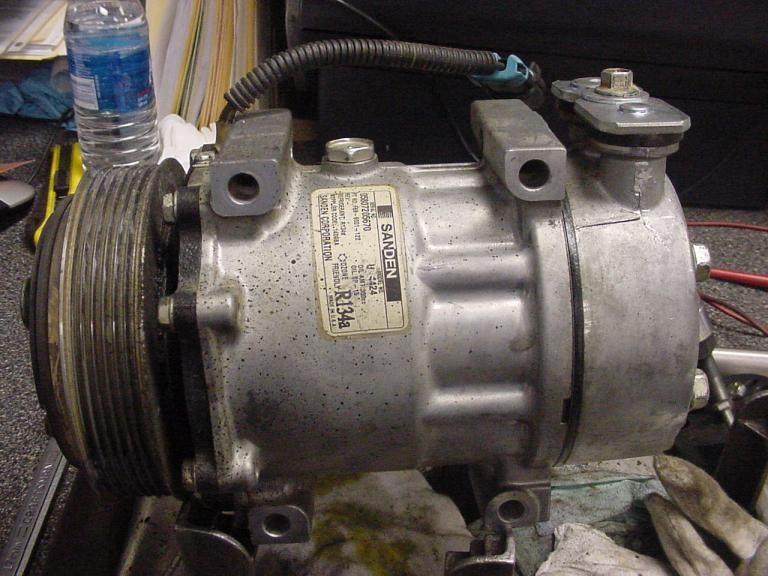
1 Presented by: Brunno Covolan Pg. 1
2 : Introduction What is Failure Mode Analysis? Looking at the compressor to determine what was the cause of the failure. Why do we need to conduct Failure Mode Analysis? Helps us fix the system to prevent further damage. Helps understand what we need to do. How do we conduct a Failure Mode Analysis? Open the compressor. Examine the compressor and analysis the broken pieces. Pg. 2
3 : Common Failures Common Failures Failures can be caused at 2 different times of a compressors life During Installation During Operation The following slides will examine the common failures at each of the individual stages Pg. 3
4 : Common Failures Common Failures During Installation Error Damage to pipe fittings, threads, and O-rings Damage to rotor or armature Crack on ear mount Wrong coil polarity Inadequate refrigerant charge Insufficient oil amount Failure mode Refrigerant leaks Noise, burned clutch, rotor bearing collapsed Refrigerant leaks, mounting failure No clutch engagement diode failure Compressor seizure Compressor seizure Pg. 4
5 : Common Failures Common Failures During Operation Error Expansion Valve problems Obstructed hoses/pipes Leaks through porosity Failure mode Compressor seizure Compressor seizure Compressor seizure Pg. 5
6 : Common Failures Common Failures During Operation The pressure switch on high pressure side may not protect in case of small leak The pressure curve in static circuit depends only on the ambience temperature Vapour pressure R134a Pressure (Bar abs) LIQUID GAS T ºC GAS LIQUID Pg. 6

7 : Common Failures Contamination Common Failures During Operation Particles introduced during installation System was not flushed before installation of compressor Defective receiver dryer/ accumulator, desiccant Pg. 7

8 : Common Failures Common Failures During Operation Accumulation of liquid refrigerant in the compressor Noise, burned clutch Washout Piston damage Presence of moisture Acid formation, corrosion TXV blockage Pg. 8
9 : Compressor Teardown Compressor Teardown Procedure When tearing down a compressor to determine failure mode, it is important to follow the correct procedure. These procedures ensure that nothing will be missed and that the correct diagnosis is found. Item Check Point 1 Check body for damages hits, corrosion, overheat 2 Check electrical connection Wire cut, original connector 3 Check ports O-rings, threads, particles 4 Check clutch air gap Between 0.4mm to 0.8mm 5 Check armature plate Leaf spring, deformation, overheating 6 Check pulley Hit marks, noise, smooth rotation 7 Check coil Resistance, diode 8 Check oil plug Torque 15Nm 9 Check oil quality Color 10 Check compressor shaft rotation Smooth rotation Pg. 9
10 : Compressor Teardown Compressor Teardown Procedure Item Check Point 11 Remove armature plate Surface not glassed 12 Remove Pulley Check snap ring fitment 13 Remove Coil Check snap ring fitment 14 Remove felt ring Not saturated with oil 15 Remove cylinder head 16 Check valve plate - Check for even torque - Check liquid line, signs of overheating Check deformation, overheating, particles 17 Check pistons Overheating, particles 18 Open front housing - Check for even torque - O-rings, particles, overheating 19 Pull out pistons piston rings, centering ball, gears 20 Cylinder block Particles, cracks Pg. 10
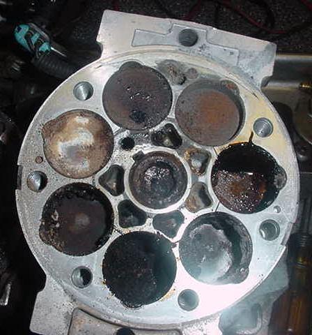
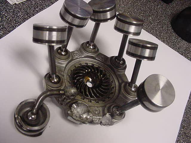
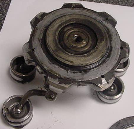
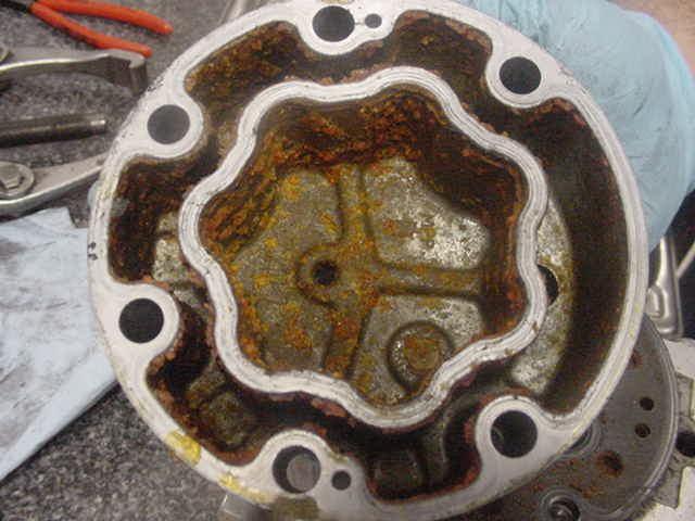
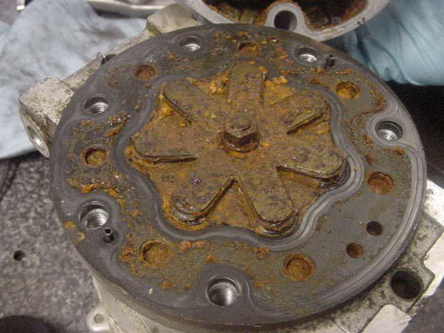
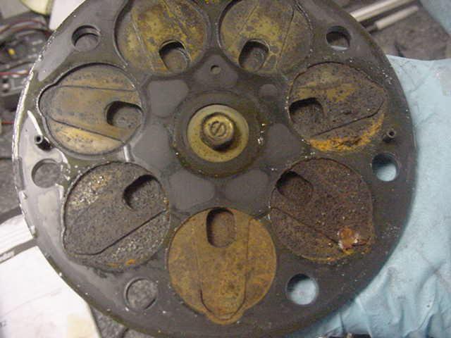
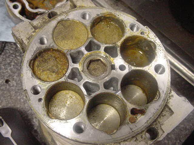
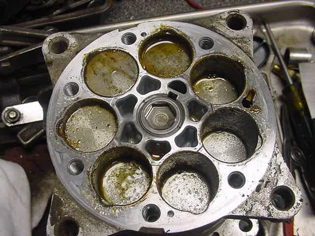
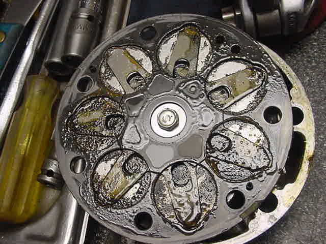
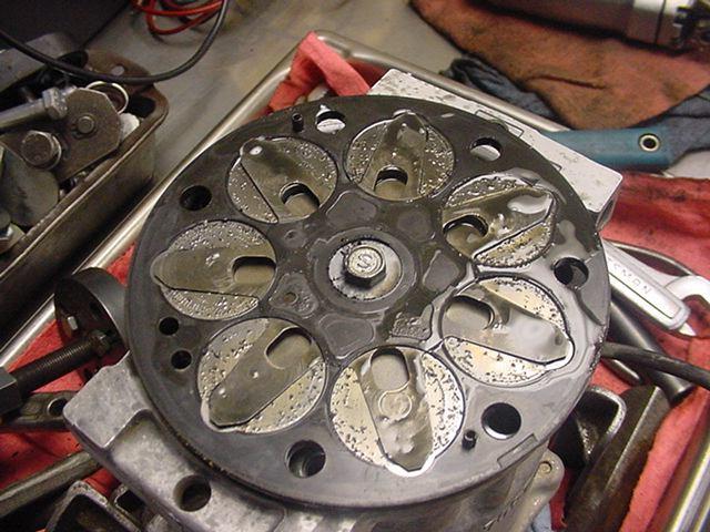
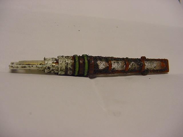
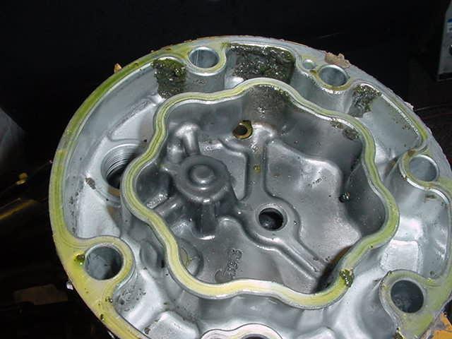
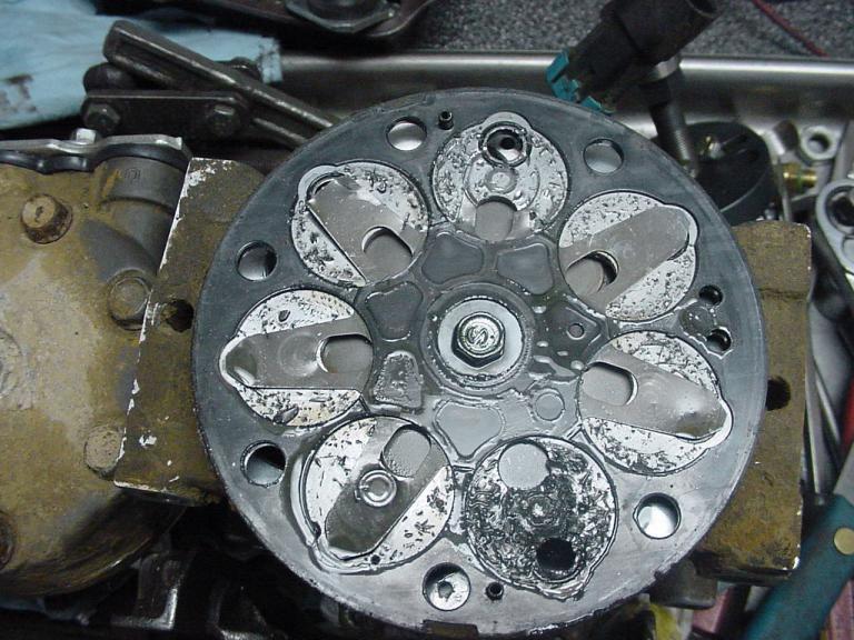
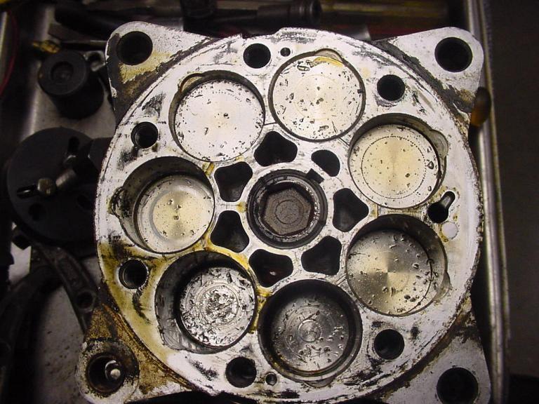
11 : Introduction Lets take a look at some examples How this will work 1: We will see a set of pictures representing the same problem. 2: We will discuss what we see on every picture. 3: At the end we will discuss the problem. Pg. 11
12 Pg. 12
13 Pg. 13
14 Pg. 14
15 Pg. 15
16 Pg. 16
17 Pg. 17
18 Pg. 18
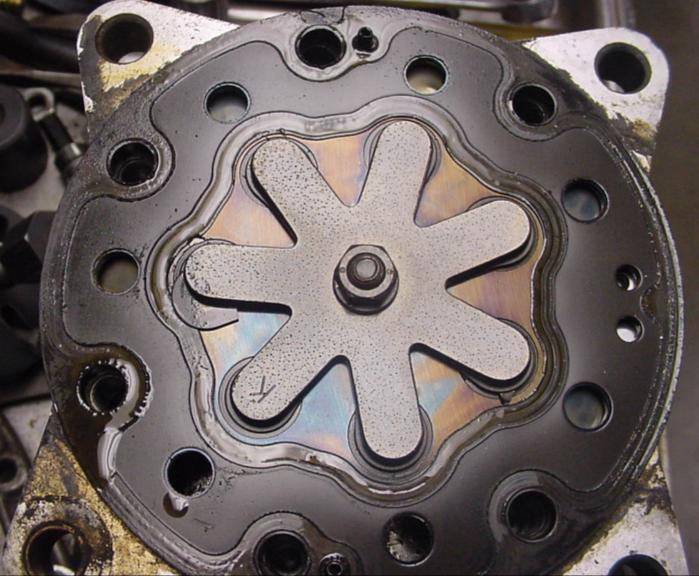
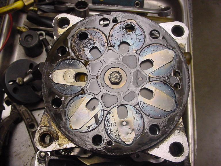
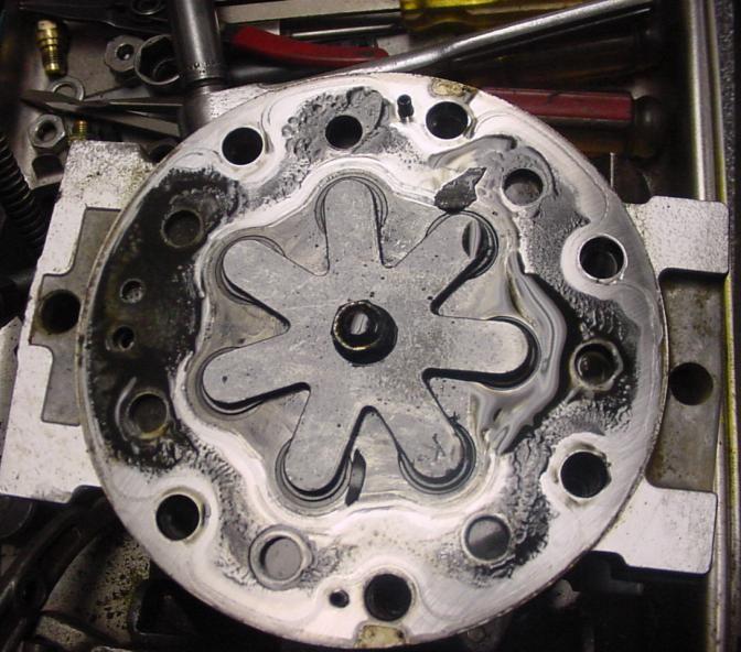
19 What do you think is the problem? Overheating. Overheating occurs when there is a lack of oil in the compressor. What could cause low oil amount? Liquid compression. System blockage. Lets go to the next set Pg. 19
20 Pg. 20
21 Pg. 21
22 Pg. 22
23 Pg. 23
24 What do you think is the problem? Moisture in system. Moisture + Oil + Refrigerant + Heat will cause acid to form and corrode lines and compressor. How to avoid this issue? Vacuum. Replace receiver dryer every time the system is opened. Pg. 24
25 Pg. 25
26 Pg. 26
27 What do you think is the problem? Dye non-compatibility. How to avoid this issue? Check for compatibility. Research receiver dryer. Pg. 27
28 Pg. 28
29 Pg. 29
30 Pg. 30

31 Pg. 31
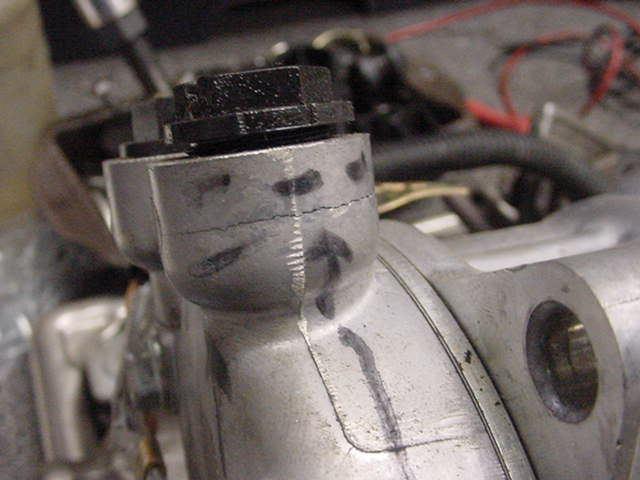
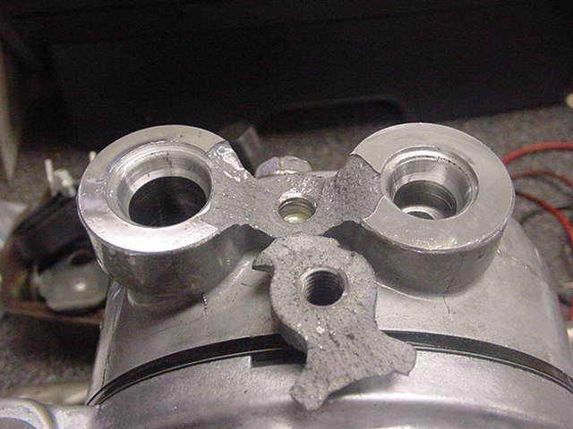
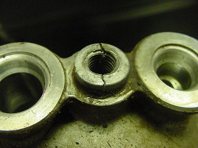
32 What do you think is the problem? Improper installation. To much torque when installing ports. How to avoid this issue? Use torque wrench. Pg. 32
33 Pg. 33
34 Pg. 34
35 Pg. 35
36 Pg. 36
37 Pg. 37
38 What do you think is the problem? Contamination. Partials from other components and past failures. How to avoid this issue? Flush system before installing new component. Replace broke components. Pg. 38


39 DIAGNOSIS BY OIL COLOR Clear oil or oil with UV tracer : Compressor probably inside O.K. Silver-grey oil : Foreign particle from A/C System or internal seizure Black oil : AC system overheated due to malfunction of condenser, defect pressure switch or lack of refrigerant Orange oil : Contamination with humidity Pg. 39

40 Pg. 40
COMPRESSORS REPLACEMENT PROCEDURE
 COMPRESSORS REPLACEMENT PROCEDURE INTRODUCTION Shown below, you can find the procedure that you must follow to replace compressors. INSTALLATION INSTRUCTION Steps to follow: 1) Remove the damaged compressor
Compressor Installation Guide. Technical helpline :
 Compressor Installation Guide Technical helpline : 0843 330 4097 Compressor Installation All air-conditioning repairs should only be undertaken by someone that has sufficient knowledge and training that
Sanden International (USA), Inc. An ISO/TS Company 4/9/2012
, Inc. An ISO/TS Company 4/9/2012") Sanden International (USA), Inc. An ISO/TS 16949-2002 Company www.sanden.com 1 Sanden International (U.S.A.), INC SD COMPRESSORS ALL NEW OEM COMPRESSORS Sanden International (USA), Inc. began marketing
Sanden International (USA), Inc. An ISO/TS 16949-2002 Company www.sanden.com 1 Sanden International (U.S.A.), INC SD COMPRESSORS ALL NEW OEM COMPRESSORS Sanden International (USA), Inc. began marketing
To determine if an A/C clutch should be returned for Warranty Consideration:
 Warranty is a growing concern for all partners in the distribution of A/C Components. Because of the growing number of warranty questions, please study the following pictures to familiarize yourself with
PRESSURE CABINETS PROBLEM CAUSE SOLUTION
 BLAST CABINET TROUBLESHOOTING Page 1 PRESSURE CABINETS 1. Poor Visibility. Motor rotating backwards. The motor should rotate as indicated by the arrow on the housing. If it does not rotate in the proper
A/C SYSTEM GENERAL DIAGNOSTIC PROCEDURES
 Article Text ARTICLE BEGINNING 1993 AIR CONDITIONING & HEAT A/C General Diagnostic Procedures Diagnosis is an important first step in A/C system servicing. To save time and effort, systems should be carefully
Table of Contents. 4. Before a New Turbocharger is Installed
 Table of Contents 1. Turbocharger Overview ------------------------------------------------------------------ 1.1. Definition -----------------------------------------------------------------------------
Badger Truck Refrigeration, Inc. Warranty Policy
 Badger Truck Refrigeration, Inc. Warranty Policy The manufacturer warrants each new heater, air conditioner or part to be free from defects in materials and workmanship under conditions of normal use and
Service Instruction ENGINE COMPONENTS, INC.
 Title: Service Instruction S.I. No.: 89-5-1 Page: 1 of 5 Issued: 05/05/89 Revision: 1 (09/01/01) Technical Portions of FAA DER Approved. FAILURE OF ENGINE TO START 27 points 1. Lack of fuel 2. Ignition
Repair any problems or leaks before retrofitting. Affix labels to the vehicle showing conversion status. Observe all safety recommendations.
 The use of R134a in mobile A/C systems designed for R-1 2 refrigerant causes higher discharge pressures (as much as 10-15%) and necessitates changing the compressor lubricant from mineral oil (5GS) to
1) Scheduled maintenance checks
 Scheduled maintenance checks") 1) Scheduled maintenance checks Definition This section lists the periodic inspections which must be carried out after a specified periods of operation. Intervals Periodic inspections are those which must
1) Scheduled maintenance checks Definition This section lists the periodic inspections which must be carried out after a specified periods of operation. Intervals Periodic inspections are those which must
DESCRIPTION AND OPERATION
 412-03-1 Air Conditioning 412-03-1 DESCRIPTION AND OPERATION Air Conditioning Refrigerant flow into the evaporator core is metered The air conditioning system components are: by an evaporator core orifice
Warranty Approval. Visual Inspection of Starters & Alternators
 Warranty Approval Visual Inspection of & Alternators Is it Genuine Delco Remy? 37MT, 41MT & 42MT Older Delco Remy stamp Current ink stamping 38MT & 39MT Current stamping Current reman label Stamped customer
6-3. Examining Failures
 SERVICE BULLETIN EXAMINING COMPRESSOR FAILURES IN THE FIELD This guide can be used as a reference to diagnose compressor failures, and is specifically designed to help you differentiate between unwarrantable
Call the A/C Experts SD Compressor Service Guide
 Call the A/C Experts SD Compressor Service Guide Table of Contents 1. Compressor Models Covered 2. Compressor Nomenclature 3. Cautionary Information 3.1 Pressure Release 3.2 Recovery of Refrigerant 3.3
STARTING/CHARGING SYSTEMS Brought to you by Eris Studios NOT FOR RESALE
 STARTING/CHARGING SYSTEMS General Description 1. General Description A: SPECIFICATION Vehicle model Starter Generator Item Specification Type Reduction type Model 428000-5760 Manufacturer DENSO Voltage
SERVICE BULLETIN EXAMINING COMPRESSOR FAILURES IN THE FIELD
 Form #COM-304AS SERVICE BULLETIN EXAMINING COMPRESSOR FAILURES IN THE FIELD This guide can be used as a reference to diagnose compressor failures, and is specifically designed to help you differentiate
Jeep Wrangler TJ 4.0 LITER Installation instructions
 www.jeepair.com 2000-2001 Jeep Wrangler TJ 4.0 LITER Installation instructions Important information about your system, and warranty DO NOT ADD ANY OIL TO ANY PART OF THE SYSTEM. DO NOT USE THE SIGHT GLASS
REMY TECHNICAL SERVICE BULLETIN
 June 2018 REMY TECHNICAL SERVICE BULLETIN Remy Power Products is continuously adding technical training and technical information. We welcome suggestions. If there is something technical you would like
Turbocharger Warranty Analysis Guidelines
 Turbocharger Warranty Analysis Guidelines Authorized Agent Use Only INTERSTATE-McBEE, LLC 5300 Lakeside Avenue Cleveland, Ohio 44114 U.S.A. 216-881-0015 Toll Free: 1-800-321-4234 Fax: 216-881-0805 www.interstate-mcbee.com
Typical Install Instructions
 Typical Install Instructions Read & understand all steps of these instructions before beginning this installation. WEBER Conversion Kit, VW T-1/2, up to 1835cc 32 / 36 DFEV Weber Carburetor These instructions
 Page 1 of 50 Section 412-00: Climate Control System General Information DIAGSIS AND TESTING 1997 Mark VIII Workshop Manual Climate Control System Special Service Tool(s) 73 Digital Multimeter 105-R0051
HEATER, AIR CONDITIONER AND VENTILATION
 55-1 HEATER, AIR CONDITIONER AND VENTILATION CONTENTS HEATER AND MANUAL AIR CONDITIONER...................... 3 GENERAL............................... 3 Outline of Change......................... 3 SERVICE
A/C COMPRESSOR SERVICING
 A/C COMPRESSOR SERVICING 1998 Mitsubishi Montero 1998 GENERAL SERVICING Mitsubishi - Compressor Servicing Diamante, Eclipse, Galant, Mirage, Montero, Montero Sport & 3000GT A/C COMPRESSOR APPLICATIONS
Section 10 Chapter 7
 Section 10 Chapter 7 24 Valve, 8.3 Liter Engine Troubleshooting Symptoms Identification Note: All coding used in the 8.3 Liter and 9 Liter engine manuals are Cummins engine codes. These engine codes have
2003 Mustang Workshop Manual
 Page 1 of 6 SECTION 412-03: Air Conditioning 2003 Mustang Workshop Manual DESCRIPTION AND OPERATION Procedure revision date: 06/14/2002 Air Conditioning Printable View (225 KB) The A/C refrigerant system
A/C COMPRESSOR CLUTCH
 BR/BE CONTROLS 24-13 A/C COMPRESSOR CLUTCH DESCRIPTION The compressor clutch assembly consists of a stationary electromagnetic coil, a hub bearing and pulley assembly, and a clutch plate (Fig. 4). The
Hydraulic Maintenance & Troubleshooting. Content - Norman Kronowitz Presenter Jim Trinkle
 Hydraulic Maintenance & Troubleshooting Content - Norman Kronowitz Presenter Jim Trinkle Introduction Welcome to the CMA/Flodyne/Hydradyne s Hydraulic Troubleshooting presentation. We will introduce many
COMPRESSOR REMOVAL OF MANIFOLD GAUGE SET ON VEHICLE INSPECTION AC 18 AIR CONDITIONING SYSTEM
 AC18 AIR CONDITIONING SYSTEM 5. CONNECT STOP VALVES TO SERVICE VALVES Tighten the nuts by hand. CAUTION: Do not connect the wrong valves to the high pressure and the low pressure sides. To prevent loosening
WARNINGS. Maintenance must be properly done to avoid serious injury risks. Improper maintenance can result in injury or property damage.
 Foreword This service manual has been elaborated to help service personnel to provide efficient and correct service and maintenance on the TM31 (formerly called DKS 32) compressor (for HFC-134a) for automotive
AIR COMPRESSOR OPERATING INSTRUCTION AND PARTS LIST
 AIR COMPRESSOR OPERATING INSTRUCTION AND PARTS LIST BELT TYPE IMPORTANT PLEASE MAKE CERTAIN THAT THE PERSON WHO IS TO USE THIS EQUIPMENT CAREFULLY READS AND UNDERSTANDS THESE INSTRUCTIONS BEFORE STARTING
CORE ACCEPTANCE CRITERIA
 Welcome to our Remy UK core criteria document Objective: To help you to identify old core that is in such a condition that is acceptable for return back to Remy UK for our re-manufacturing process and
BRAKE SYSTEM Return To Main Table of Contents
 BRAKE SYSTEM Return To Main Table of Contents GENERAL... 2 BRAKE PEDAL... 10 MASTER CYLINDER... 13 BRAKE BOOSTER... 16 BRAKE LINE... 18 PROPORTIONING VALVE... 19 FRONT DISC BRAKE... 20 REAR DRUM BRAKE...
AIR CONDITIONING SYSTEM
 AC-1 AIR CONDITIONING SYSTEM GENERAL INFORMATION DESCRIPTION TROUBLESHOOTING PREPARATION REFRIGERATION SYSTEM DRIVE BELT REFRIGERATION LINES COMPRESSOR RECEIVER CONDENSOR COOLING UNIT COOL/ICE BOX EVAPORATORS
DIAGNOSIS AND TESTING
 412-00-1 Climate Control System - General Information 412-00-1 DIAGNOSIS AND TESTING Climate Control System Refer to Wiring Diagrams Cell 54, Air Conditioning/Heater for schematic and connector information.
MANUAL CONTROL / SEMIAUTO TEMPERATURE CONTROL HEATING, VENTILATION AND AIR CONDITIONING SYSTEM
 SECTION 7C MANUAL CONTROL / SEMIAUTO TEMPERATURE CONTROL HEATING, VENTILATION AND AIR CONDITIONING SYSTEM CAUTION: Disconnect the negative battery cable before removing or installing any electrical unit
Important information about your new a/c system. Please read the following directions prior to installing this a/c system.
 PAGE 1 Important information about your new a/c system. Please read the following directions prior to installing this a/c system. PN s: CK-7586258, CK-758642, CK-7586304, CK7586SBC, CK-7486NC Jeep CJ Series
9/28/2018. Refrigeration compressor operation, maintenance and safety
 Refrigeration compressor operation, maintenance and safety Presented By: Dhananjay S. Deshpande Company name: Technex HVAC&R Engg. Works 304, Shivshakti CHS, Sector 09, Plot no 15, Khanda colony, New Panvel
TURBOCHARGER WARRANTY ANALYSIS GUIDELINES
 ABOUT US Rotomaster is a turbocharger manufacturing company driven by customer demand and focused on our customer s success. The quality put forth by Roto is world class utilizing modern CNC (Computerized
Troubleshooting Guide for Pumps ATD ATD ATD5289
 PROBLEM: Your pump does not work? There are Three Basic Problems! Troubleshooting Guide for Pumps ATD5217 - ATD5219 - ATD5289 Air Motor Operates but nothing comes out. This is the most common problem.
TCI TRANS-SCAT
 Page 1 of 9 Return to Instruction Sheet index TCI 360000 TRANS-SCAT Installation Instructions for FORD C-6 Transmissions TCI s TRANS-SCAT kit will allow you to calibrate the performance of your transmission.
SERVICE MANUAL. Valeo TM21Compressor. Copyright 2015 Valeo Japan CO., LTD. All rights reserved.
 SERVICE MANUAL Valeo TM21Compressor Copyright 2015 Valeo Japan CO., LTD. All rights reserved. Foreword This service manual has been elaborated to help service personnel to provide efficient and correct
TROUBLESHOOTING FLOW CHARTS
 TROUBLESHOOTING FLOW CHARTS Bowl Style Carburetor Troubleshooting Hunts and Surges Will Run only on Prime Will run only if the choke is used Determine that the governor system is functioning properly
KD Disassembly/ Assembly recommendations
 KD457.48 Disassembly/ Assembly recommendations AUDI: SKODA: VOLKSWAGEN: KD457.48/UK/01-05/2016 A4 (Series 2, 2 FL, Cabriolet), A6 (Series 2, 2FL, Allroad), A8 Superb Passat ENGINES 2.5TDi TIMING BELT DIAGRAM
Engine Does Not Start or Is Hard to Start Cause of Trouble. 1. Open the drain screw, and check Fuel not supplied (1) Fuel tank empty
 Fuel tank empty") 20. Engine Does Not Start or Is Hard to Start 20-1 Engine Output Insufficient 20-2 Poor Performance at Low Speed and Idling 20-3 Poor Performance at High Speed 20-3 Unsatisfactory Operation 20-4 Fuel Gauge
20. Engine Does Not Start or Is Hard to Start 20-1 Engine Output Insufficient 20-2 Poor Performance at Low Speed and Idling 20-3 Poor Performance at High Speed 20-3 Unsatisfactory Operation 20-4 Fuel Gauge
ANTI-SKID BRAKING SYSTEM (ABS)
") GROUP 35B ANTI-SKID BRAKING SYSTEM (ABS) CONTENTS GENERAL INFORMATION........ 35B-2 SERVICE SPECIFICATIONS....... 35B-4 SPECIAL TOOLS................ 35B-5............ 35B-6 STANDARD FLOW OF DIAGNOSTIC................
GROUP 35B ANTI-SKID BRAKING SYSTEM (ABS) CONTENTS GENERAL INFORMATION........ 35B-2 SERVICE SPECIFICATIONS....... 35B-4 SPECIAL TOOLS................ 35B-5............ 35B-6 STANDARD FLOW OF DIAGNOSTIC................
2014 Buick Encore. Fig. 2: Replacing Measured Compressor Oil Courtesy of GENERAL MOTORS COMPANY
 Fig. 2: Replacing Measured Compressor Oil Courtesy of GENERAL MOTORS COMPANY 2. Add back the same quantity of polyalkylene glycol (PAG) oil as drained from the removed air conditioning compressor. Refer
GROUP CONTENTS GENERAL DESCRIPTION RADIATOR SPECIAL TOOL THERMOSTAT ENGINE COOLING DIAGNOSIS...
 14-1 GROUP 14 CONTENTS GENERAL DESCRIPTION 14-2 SPECIAL TOOL 14-2 ENGINE COOLING DIAGNOSIS 14-3 INTRODUCTION 14-3 TROUBLESHOOTING STRATEGY 14-3 SYMPTOM CHART 14-3 SYMPTOM PROCEDURES 14-4 ON-VEHICLE SERVICE
Instruction Manual. Table of Contents. Powder Clutch, Brake MODEL ZKB-AN,BN Powder Clutch ZKB-YN,XN Powder Brake
 ZJ-267A Powder Clutch, Brake MODEL ZKB-AN,BN Powder Clutch ZKB-YN,XN Powder Brake Instruction Manual Table of Contents Cautions on Safety - - - - - - - - - - - - - - - - - 1 1. Cautions before use - -
ENGINE COOLING GROUP CONTENTS GENERAL INFORMATION SERVICE SPECIFICATIONS COOLANT SEALANT THERMOSTAT...
 14-1 GROUP 14 CONTENTS GENERAL INFORMATION 14-2 SERVICE SPECIFICATIONS 14-2 COOLANT 14-3 SEALANT 14-3 DIAGNOSIS 14-3 INTRODUCTION 14-3 TROUBLESHOOTING STRATEGY 14-3 SYMPTOM CHART 14-3 SYMPTOM PROCEDURES
MAINTENANCE GUIDE Rotary joint
 MAINTENANCE 7. Filter in Cooling System Cleaning interval Replace earlier if badly contaminated. Heater performance will deteriorate if used for a long period of time without cleaning or replacement. Clogging
So some of the world famous brands adopt QP compressors for their ac or refrigeration units, such as
 Zhengzhou Guchen industry Co., Ltd. as the distributor (OEM) of QP series compressors supplies original imported QP compressors and other original compressor spare parts for refrigeration units with competitive
ON-VEHICLE INSPECTION
 CH2 P11586 CHARGING CHARGING SYSTEM ONVEHICLE INSPECTION 1. CHECK BATTERY ELECTROLYTE LEVEL Check the electrolyte quantity of each cell. MaintenanceFree Battery: CH03L01 If under the lower level, replace
6 Litre Oil-Less Air Compressor
 Operator s Manual 6 Litre Oil-Less Air Compressor WARNING! Before using this appliance, read the Operator s manual and follow all its safety rules and instructions. SPECIFICATION HWKAC1 1.1 kw / 1.5 HP
Total Preventative Maintenance Autonomous Maintenance
 Total Preventative Maintenance Autonomous Maintenance Step 0 and 1 (Part 2) Program Initiation Autonomous Maintenance Focussed Improvement Effective Maintenance Education and Training Early Management
ENGINE COOLING GROUP CONTENTS GENERAL INFORMATION SERVICE SPECIFICATIONS COOLANT SEALANT THERMOSTAT...
 14-1 GROUP 14 CONTENTS GENERAL INFORMATION 14-2 SERVICE SPECIFICATIONS 14-2 COOLANT 14-3 SEALANT 14-3 DIAGNOSIS 14-3 INTRODUCTION 14-3 TROUBLESHOOTING STRATEGY 14-3 SYMPTOM CHART 14-3 SYMPTOM PROCEDURES
Cooling System. Water Pump. Radiator
 The cooling system is engineered to remove waste heat from the engine cylinder block and cylinder head to prevent damage caused by overheating of those components. The waste heat is transferred through
Class 5 to 7 Truck and Bus Hydraulic Brake System
 Class 5 to 7 Truck and Bus Hydraulic Brake System Diagnostic Guide 2nd Edition www.bosch.us Important Service tes The information in this publication was current at the time of printing. The information
STEERING HYDRAULICS The steering system is a flow amplified, load sensing, hydraulics arrangement.
 STEERING HYDRAULICS 116821 The steering system is a flow amplified, load sensing, hydraulics arrangement. When the steering wheel is turned, the Steering Metering Pump meters an oil volume proportional
Brake discs and Brake pads. Typical damage patterns and their causes
 Brake discs and Brake pads Typical damage patterns and their causes Good brakes save lives! You see the pretty curves, underneath is what counts. The consequences of choosing the wrong or low-grade brake
6L Oil-less Air Compressor 53103
 6L Oil-less Air Compressor 53103 Operating Instructions Please read and save these instructions before attempting to assemble, install, operate or maintain the product. Protect yourself and others by observing
CHAPTER 21 ENVIRONMENT CONTROL. Section Title Page
 CHAPTER 21 ENVIRONMENT CONTROL Section Title Page 21-00 Description........................................ 21.1 21-10 Ventilation........................................ 21.3 21-11 Nose Vent................................
SECTION 4A BRAKE SYSTEM TABLE OF CONTENTS
 SECTION 4A BRAKE SYSTEM TABLE OF CONTENTS Description and Operation... 4A-2 Braking System Testing... 4A-2 Hydraulic Brake System... 4A-2 Brake Pedal... 4A-2 Master Cylinder... 4A-2 Brake Booster... 4A-3
Failure Analysis System Procedure. Submersible Vertical Pumps SVI. Lowara. 1) Electric pump applications
 Electric pump applications") Failure Analysis System Procedure Submersible Vertical Pumps SVI 1) Electric pump applications Pumping of cooling liquids, lubricating and condensate Machine tool, welding machine, motor test-bed Cooling
Failure Analysis System Procedure Submersible Vertical Pumps SVI 1) Electric pump applications Pumping of cooling liquids, lubricating and condensate Machine tool, welding machine, motor test-bed Cooling
Hydraulic Brake System, Bosch 42.15
 Hydraulic Brake System, Bosch 42.15 Index Hydraulic Brake Index Subject Figure Brake warning lamp and buzzer related to parking brake Fig. 1 Brake warning lamp and buzzer related to service brake Fig.
Compressor - Install (E.40.C.31 - F.10.A.15)
") Compressor - Install (E.40.C.31 - F.10.A.15) 1. Set the compressor on its mount and secure into place using the four bolts. Connect the refrigerant suction line (5) and the discharge line (4). Install
Compressor - Install (E.40.C.31 - F.10.A.15) 1. Set the compressor on its mount and secure into place using the four bolts. Connect the refrigerant suction line (5) and the discharge line (4). Install
TURBOCHARGER Toyota Celica DESCRIPTION OPERATION TURBOCHARGING SYSTEMS All Models
 TURBOCHARGER 1988 Toyota Celica 1988 TURBOCHARGING SYSTEMS All Models DESCRIPTION Most models use a water-cooled turbocharger, mounted directly to the exhaust manifold with a wastegate assembly attached
BASIC BRAKE SYSTEM GROUP 35A 35A-1 CONTENTS GENERAL DESCRIPTION... 35A-3 BASIC BRAKE SYSTEM DIAGNOSIS 35A-6
 35A-1 GROUP 35A BASIC BRAKE SYSTEM CONTENTS GENERAL DESCRIPTION......... 35A-3 DIAGNOSIS 35A-6 INTRODUCTION..................... 35A-6 DIAGNOSTIC TROUBLESHOOTING STRATEGY......................... 35A-6
7-6 COOLING KJ COOLING (Continued) COOLING SYSTEM DIAGNOSIS CHART - GAS ENGINE COOLING SYSTEM DIAGNOSIS CHART CONDITION POSSIBLE CAUSES CORRECTION TEM
 COOLING SYSTEM DIAGNOSIS CHART - GAS ENGINE COOLING SYSTEM DIAGNOSIS CHART CONDITION POSSIBLE CAUSES CORRECTION TEM") 7-6 COOLING KJ COOLING (Continued) COOLING SYSTEM DIAGNOSIS CHART - GAS ENGINE COOLING SYSTEM DIAGNOSIS CHART CONDITION POSSIBLE CAUSES CORRECTION TEMPERATURE GAUGE READS LOW 1. Has a Diagnostic Trouble
7-6 COOLING KJ COOLING (Continued) COOLING SYSTEM DIAGNOSIS CHART - GAS ENGINE COOLING SYSTEM DIAGNOSIS CHART CONDITION POSSIBLE CAUSES CORRECTION TEMPERATURE GAUGE READS LOW 1. Has a Diagnostic Trouble
PowerLink GW series Eddy Current Dynamometer User Manual
 PowerLink GW series Eddy Current Dynamometer User Manual XiangYi (Hong Kong) Power Testing Instrument Co. Ltd. 0 GW Series Eddy Current Dynamometer User Manual Transport, Storage, use of environmental
A/C PRESSURE MONITOR INSTALLATION INSTRUCTIONS SYSTEM OPERATION GREEN INDICATOR LIGHT
 A/C PRESSURE MONITOR INSTALLATION INSTRUCTIONS Do not attempt to clean or inspect anything while the engine is running. Cleaning and inspection must be done by a certified mechanic. All A/C service must
TROUBLE SHOOTING - BASIC PROCEDURES
 TROUBLE SHOOTING - BASIC PROCEDURES 1990 Nissan 240SX GENERAL TROUBLE SHOOTING * PLEASE READ THIS FIRST * NOTE: This is GENERAL information. This is not intended to be specific to any unique situation
Before you go through this booklet, we request you to go through the following general instruction before commissioning your hydraulic systems.
 Hello, We are proud to be on your suppliers list. During few years we came to know that most of our customers are satisfied by Yuken Hydraulic Products but some of our customers had minor problems and
LG Air Conditioning Universal & Multi Split Fault Codes Sheet. Universal and Multi Split Units
 Universal and Multi Split Units If there is a fault on any LG Universal or Multi unit, a two digit number will appear on the remote controllers led display. If the unit does not have a remote controller
Refrigerant Oil Calculation during Compressor Replacement
 Refrigerant Oil Calculation during Compressor Replacement Study Guide TMT: 100820 Dealer Education 2008 Navistar, Inc. 4201 Winfield Road, Warrenville, IL 60555. All rights reserved. No part of this publication
PNEUMATICS CONTENTS HST-TAMPER
 CONTENTS Tamper Pneumatic Component Locations...2 Manually Releasing Air Brakes... 3 Releasing Air Pressure... 4 Removing Water from Air Tanks... 4 Adjusting Air Compressor Governor... 4 Check/Replace
Manual A/C System Components in Engine Compartment, Servicing
 Page 1 of 5 Volkswagen > A4 > 1999-2006 Heating, Ventilation and Air Conditioning 87 - Manual A/C System Manual A/C System Components in Engine Compartment, Servicing CAUTION! Before beginning repairs:
ORDER ON-LINE /
 NM249 NM248 INTERNAL SYSTEMS FOR TRAILERS INSTALLATION MANUAL VERSION 1-2013 ORDER ON-LINE www.vigia.ca / 1-888 438-8444 IMPORTANT Installation requires an experienced mechanic with knowledge of tools
GATES POWERGRIP TIMING BELTS MENU
 GATES POWERGRIP TIMING BELTS MENU PowerGrip timing belt installation PowerGrip timing belt troubleshooting guide More about PowerGrip timing belts GATES POWERGRIP TIMING BELTS INSTALLATION Timing Belt
What is Wear? Abrasive wear
 What is Wear? Written by: Steffen D. Nyman, Education Coordinator, C.C.JENSEN A/S It is generally recognized that contamination of lubricating and hydraulic oils are the primary cause of wear and component
BLISS PELLET MILL 200
 BLISS PELLET MILL 200 TORQUE GUIDE 200 PELLET MILL The Brake B-loc 112 series torque 225nm The Brake b-loc 115 series torque 142nm Mainshaft nut Drive belt 250 mm Drive belt 340mm Roll settings Gap for
GROUP 35A 35A-1 CONTENTS GENERAL DESCRIPTION... 35A-3 BASIC BRAKE SYSTEM DIAGNOSIS 35A-6 HYDRAULIC BRAKE BOOSTER (HBB) DIAGNOSIS...
 DIAGNOSIS...") 35A-1 GROUP 35A CONTENTS GENERAL DESCRIPTION......... 35A-3 DIAGNOSIS 35A-6 INTRODUCTION..................... 35A-6 DIAGNOSTIC TROUBLESHOOTING STRATEGY......................... 35A-6 SYMPTOM CHART...................
35A-1 GROUP 35A CONTENTS GENERAL DESCRIPTION......... 35A-3 DIAGNOSIS 35A-6 INTRODUCTION..................... 35A-6 DIAGNOSTIC TROUBLESHOOTING STRATEGY......................... 35A-6 SYMPTOM CHART...................
SUSPENSION 2-1 SUSPENSION TABLE OF CONTENTS
 XJ SUSPENSION 2-1 SUSPENSION TABLE OF CONTENTS page ALIGNMENT... 1 FRONT SUSPENSION... 7 page REAR SUSPENSION... 16 ALIGNMENT TABLE OF CONTENTS page AND WHEEL ALIGNMENT...1 DIAGNOSIS AND TESTING SUSPENSION
Fault Codes. J control
 J control Timer Temp Fault Codes 12 11 10 9 8 7 6 5 4 3 2 1 30 29 28 27 26 25 24 23 22 21 20 Enter unit inspection mode by pushing the UP and DOWN buttons simultaneously for two seconds. Ensure that the
D-04/G-04 Maintenance
 D-04/G-04 Maintenance NOTE: The numbers in parentheses are the Ref. Nos. on the illustrations in the Parts Manual. Daily Check the oil level and the condition of the oil. The oil level should be 1/4 in.
A/C COMPRESSOR SERVICING Article Text 1991 Saab 9000 For Copyright 1997 Mitchell International Friday, October 15, :22PM
 Article Text ARTICLE BEGINNING 1991 GENERAL SERVICING Compressor Service * PLEASE READ THIS FIRST * CAUTION: When discharging air conditioning system, use only approved refrigerant recovery/recycling equipment.
LG Air conditioning CAC and Multi Split unit Fault code sheet Universal and Multi Split Units
 Universal and Multi Split Units If there is fault on any LG universal or multi unit a two digit number will appear on the remote controllers led display. If the unit does not have a remote controller the
Water pump diagnosis module
 DT-VEC-01 2014 I Engine Cooling I Water pump I Warranty diagnosis tool I Information Water pump diagnosis module Introduction In order to give a support to his customers during warranty analysis, Valeo
Your Brakes. Fundamentals of Braking
 B U S S E R V I C E, I N C. Your Brakes Fundamentals of Braking There are a variety of mechanical forces and physical components that make up the braking system of your coach. The forces that effect your
1.8L & 2.2L 4-CYL Article Text 1998 Subaru Impreza
 1.8L & 2.2L 4-CYL Article Text 1998 Subaru Impreza ARTICLE BEGINNING 1995-98 ENGINES Subaru - 1.8L & 2.2L 4-Cylinder 1995-97: Impreza (1.8L) 1995-98: Impreza (2.2L), Legacy (2.2L) * PLEASE READ THIS FIRST
Service Manual. Climate Control Inc.
 SECTION 2 Service - Clutch Servicing (Removal & Installation) - Shaft Seal Servicing (Removal & Installation) - Head & Valve Plate Servicing (Removal & Installation) - Baseplate Servicing (Removal & Installation)
Troubleshooting:Passenger Car
 Troubleshooting:Passenger Car Troubleshooting If the engine or other parts has the problem, it is possible to break the exchange turbocharger again. Please confirm the notes below and inspect each part
UX330 Compressor Service Manual
 UX330 Compressor Service Manual UX330 Compressor Service Manual Table of contents: 1. Specifications UX330. 1 Magnetic clutch 2 2. Component part list I. Compressor part numbers 3 II. Exploded view 4 3.
INSTALLATION INSTRUCTIONS
 INSTALLATION INSTRUCTIONS Accessory Application Publications No. AIR CONDITIONER CIVIC 2- AND 4-DOOR AII 24158 Issue Date SEP 2002 What s New The installation instructions for the 2003 Civic A/C are the
IMPORTANT FITTING INSTRUCTIONS PLEASE READ THESE INSTRUCTIONS BEFORE FITTING YOUR TURBO. FAILING TO FOLLOW THEM COULD INVALIDATE THE WARRANTY.
 IMPORTANT FITTING INSTRUCTIONS! PLEASE READ THESE INSTRUCTIONS BEFORE FITTING YOUR TURBO. FAILING TO FOLLOW THEM COULD INVALIDATE THE WARRANTY. 1WHY DID THE LAST TURBO FAIL? Turbochargers are very reliable:
Maintenance Information
 Form 16575334 Edition 1 April 2005 Electric Screwdrivers EL, EP and ET 34V DC Series Maintenance Information Save These Instructions WARNING Maintenance procedures have the potential for severe shock hazard
REMOVAL AND INSTALLATION
 412-03-1 Air Conditioning 412-03-1 REMOVAL AND INSTALLATION Clutch and Clutch Field Coil Special Tool(s) 2-Jaw Puller 205-D026 (D80L-1002-L) or equivalent Special Tool(s) Installer, A/C Compressor Field
2005 Toyota RAV AUTOMATIC TRANSMISSIONS U240E & U241E Overhaul
 2001-05 AUTOMATIC TRANSMISSIONS U240E & U241E Overhaul APPLICATION CAUTION: Flush oil cooler and oil cooler lines prior to transaxle installation. Oil cooling system contamination may cause premature transaxle
2003 Explorer Sport/Sport-Trac Workshop Manual. 7. Disconnect the vacuum harness connector. Remove the nut.
 7. Disconnect the vacuum harness connector. Remove the nut. 8. Remove two nuts, one bolt, and the A/C evaporator housing (19850). Remove the nut located at the bottom of the A/C evaporator housing first.
FRONT SUSPENSION GROUP 33A 33A-1 CONTENTS GENERAL DESCRIPTION... 33A-2 FRONT SUSPENSION DIAGNOSIS. 33A-3 LOWER ARM... 33A-13 SPECIAL TOOLS...
 33A-1 GROUP 33A FRONT SUSPENSION CONTENTS GENERAL DESCRIPTION......... 33A-2 DIAGNOSIS. 33A-3 INTRODUCTION TO DIAGNOSIS........................ 33A-3 DIAGNOSIS TROUBLESHOOTING STRATEGY...... 33A-3 SYMPTOM