Transmission Disassembly
|
|
|
- Domenic May
- 5 years ago
- Views:
Transcription
1 TRANSMISSION SYSTEM F8B( 800 CC Car)

2 Transmission system
3 Components Name
4 Transmission Disassembly
5 Shifting Shaft & Fork

6 TRANSMISSION ASSY: M/T The transmission provides four forward speeds and one reverse speed by means of Four synchronizers, Two Hub & Sleeve and three shafts: 1. Input shaft, 2. Counter shaft 3. Differential Gear All forward gears are in constant mesh with Synchronizer and reverse uses a sliding idler gear arrangement. Hub and Sleeve Input Shaft gears / Rev gear Counter Shaft gears
7 TRANSMISSION ASSY: M/T High speed sleeve & hub Transmission case speed sleeve & hub Low speed sleeve & hub Reverse gear shaft Input shaft Counter Shaft Output shaft Differential bevel gear Ring gear


8 PARTS DISCRIPTION Speed Gear: Transmits power from one shaft to other as per gear ratio. Synchroniser ring: Facilitates smooth engagement of gear as work as a guide for sliding sleeve. Hub & Sleeve: Sleeve moves over hub and engaging gear with hub so as transmit power from gear to output shaft. Gear Shift Fork : Through h gear shift fork sleeve moves over hub.
9 a PARTS DISCRIPTION Gear Shift Shaft: It selects the gear as per the movement of gear selector shaft. Fork (a) and (b) is fixed on the shaft. Fork (a) takes the movement from gear selector shaft b and moves gear shift shaft and fork (b) results in engagement of gear. Input Shaft (1) : Takes power from engine through clutch assy and transmits the power to countershaft through gears. Gear Selector Shaft: Takes movement from gear shifting rod and facilitates selection of gear by transmitting motion to fork.
10 I st Gear POWER TRANSMISSION II nd Gear Input from Engine Output to Wheels Indicates Power flow Indicates Movement of Sleeve Hub and Sleeve Input Shaft gears / Rev gear Counter Shaft gears
11 POWER TRANSMISSION III rd Gear IV th Gear Indicates Power flow Indicates Movement of Sleeve Hub and Sleeve Input Shaft gears / Rev gear Counter Shaft gears


12 POWER TRANSMISSION Reverse Gear Indicates Power flow Indicates Movement of Sleeve Hub and Sleeve Input Shaft gears / Rev gear Counter Shaft gears
13 GEAR RATIO Gear Ratio MT Ist Gear nd Gear rd Gear th Gear Reverse Final Gear 3.789
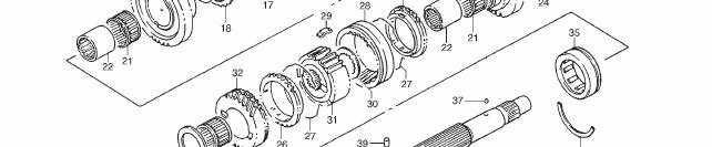
14 Counter Shaft Gear Assy Counter Shaft Needle bearing Speed gear Synchronizer ring Hub Sleeve
15 GEAR SELECTION Neutral Position Engaging 1 St &2 nd dgear ( 1 st gear) Engaging 1 St &2 nd dgear ( 2 nd gear) Spring loaded ball Gear shift guide shaft Speed gear Indicates movement of the sleeve Synchroniser ring Gear shift fork Hub Sleeve Gear selection through gear shift guide shaft
16 INSPECTION WHILE REASSEMBLY 1. Gear 2. Synchronizer ring a) Clearance a : Standard mm Service limit 0.5 mm( By Checking Feeler Gauge)
17 Assemble 3 rd &4thgear synchroniser sleeve and hub with keys and springs. Note: Short side C in keys, long boss D in hub and chamfer spline F in sleeve should face inward. ASSEMBLING TRANSMISSION UNIT


18 ASSEMBLING TRANSMISSION UNIT Install countershaft to counter shaft facing machined boss A inward. A Shift low speed gear shift to 1st gear position and high speed gear shift shaft to 3rd gear position as shown. Tighten of Counter shaft nut.
19 TROUBLE SHOOTING DIAGNOSIS Condition Possible Cause Correction Worn shift fork shaft Replace. Worn shift fork or synchronizer sleeve Replace. Gears slipping Weak or damaged locating springs Replace. out of mesh Worn bearings on input shaft or countershaft Replace. Worn chamfered tooth on sleeve and gear Replace sleeve and gear. Inadequate lubricant Replenish. Improper clutch pedal free travel Adjust. Distorted or broken clutch disc Replace. Damaged clutch pressure plate Replace clutch cover. Hard shifting Worn synchronizer ring Replace. Worn chamfered tooth on sleeve or gear Replace sleeve or gear. Worn gear shift control shaft joint bush Replace. Distorted shift shaft Replace. Inadequate or insufficient lubricant Replenish. Noise Damaged or worn bearing(s) Replace. Damaged or worn gear(s) Replace. Damaged or worn synchronizer parts Replace.
20 THANK YOU
MANUAL TRANSMISSION MUA 5C (4X2, 4X4) AND TREMEC T5R(4X2)
 AND TREMEC T5R(4X2)") MANUAL TRANSMISSION 7B 1 RODEO TRANSMISSION MANUAL TRANSMISSION MUA 5C (4X2, 4X4) AND TREMEC T5R(4X2) CONTENTS Service Precaution...................... 7B 2 General Description..................... 7B
MANUAL TRANSMISSION 7B 1 RODEO TRANSMISSION MANUAL TRANSMISSION MUA 5C (4X2, 4X4) AND TREMEC T5R(4X2) CONTENTS Service Precaution...................... 7B 2 General Description..................... 7B
MANUAL TRANS OVERHAUL - BORG-WARNER - T56 6-SPEED MANUAL TRANSMISSIONS Borg-Warner T56 (MM6) 6-Speed
 6-Speed") IDENTIFICATION MANUAL TRANS OVERHAUL - BORG-WARNER - T56 6-SPEED 1998 MANUAL TRANSMISSIONS Borg-Warner T56 (MM6) 6-Speed Transmission has 2 identification labels, located on lower left side of case. One
IDENTIFICATION MANUAL TRANS OVERHAUL - BORG-WARNER - T56 6-SPEED 1998 MANUAL TRANSMISSIONS Borg-Warner T56 (MM6) 6-Speed Transmission has 2 identification labels, located on lower left side of case. One
MANUAL TRANSAXLE Return to Main Table of Contents
 MANUAL TRANSAXLE Return to Main Table of Contents GENERAL... 2 MANUAL TRANSAXLE CONTROL... 12 SHIFT LEVER ASSEMBLY... 14 MANUAL TRANSAXLE... 15 MANUAL TRANSAXLE ASSEMBLY... 17 FIFTH SPEED SYNCHRONIZER
MANUAL TRANSMISSION SERVICE
 MANUAL TRANSMISSION SERVICE Introduction Internal combustion engines develop very little torque or power at low rpm. This is especially obvious when you try to start out in direct drive, 4th gear in a
15.Main Shaft Assembly
 15.Main Shaft Assembly A: REMOVAL 1) Remove the manual transmission assembly from vehicle. 2) Remove the transfer case with extension case assembly.
Output Shaft Assembly COMPONENTS
 MT140 Component Parts (Output Shaft Assembly Output Shaft Assembly COMPONENTS DISASSEMBLY OF OUTPUT SHAFT ASSEMBLY 1. REMOVE SLEEVE FROM OUTPUT SHAFT Using SST, remove the sleeve from the output shaft.
MANUAL TRANSMISSIONS Mitsubishi F4M20, F5M20, F5M30 & KM200 Series TRANSMISSION APPLICATION
 Article Text ARTICLE BEGINNING MANUAL TRANSMISSIONS Mitsubishi F4M20, F5M20, F5M30 & KM200 Series APPLICATION TRANSMISSION APPLICATION Vehicle Application Transmission Model Chrysler Motors (2WD) 4-Speed
OVERHAUL. 1. INSPECT 1ST GEAR THRUST CLEARANCE (a) Using a feeler gauge, measure the 1st gear thrust clearance.
 Using a feeler gauge, measure the 1st gear thrust clearance.") 4168 OVERHAUL 410F701 1. INSPECT 1ST GEAR THRUST CLEARANCE (a) Using a feeler gauge, measure the 1st gear thrust clearance. 0.10 to 0.40 mm (0.0039 to 0.0157 in.) 0.40 mm (0.0157 in.) C80538 2. INSPECT
4168 OVERHAUL 410F701 1. INSPECT 1ST GEAR THRUST CLEARANCE (a) Using a feeler gauge, measure the 1st gear thrust clearance. 0.10 to 0.40 mm (0.0039 to 0.0157 in.) 0.40 mm (0.0157 in.) C80538 2. INSPECT
Diagnostic Procedures
 Section 6 Diagnostic Procedures Learning Objectives: 1. Describe manual transmission, transaxle and transfer case component inspection and diagnostic procedures 2. Identify clutch component inspection
22-1 GROUP 22 MANUAL TRANSAXLE CONTENTS MANUAL TRANSAXLE... 22A MANUAL TRANSAXLE OVERHAUL... 22B
 22-1 GROUP 22 MANUAL TRANSAXLE CONTENTS............................... 22A OVERHAUL..................... 22B 22A-2 GROUP 22A MANUAL TRANSAXLE CONTENTS GENERAL DESCRIPTION......... 22A-3 DIAGNOSIS 22A-6
SECTION 5B MANUAL TRANSMISSION TABLE OF CONTENTS
 SECTION 5B MANUAL TRANSMISSION TABLE OF CONTENTS General Description and Operation... 5B-2 Shift Lever... 5B-2 Transmission Assembly... 5B-2 Specifications... 5B-3 Diagnostic Information and Procedures...
1994 Mitsubishi Eclipse GS
 APPLICATIONS CHRYSLER MOTORS MANUAL TRANS OVERHAUL - MITSUBISHI W5M & W6M SERIES MANUAL TRANSMISSIONS Mitsubishi W5M31, TRANSMISSION APPLICATIONS (CHRYSLER MOTORS) Vehicle Application Transmission Model
SUZUKI SQ 416/420/625 M.Y TRANSMISSION SERVICE MANUAL - MANUAL - AUTOMATIC - TRANSFER - DIFFERENTIALS
 SUZUKI SQ 416/420/625 M.Y 1998-2005 TRANSMISSION SERVICE MANUAL - MANUAL - AUTOMATIC - TRANSFER - DIFFERENTIALS WARNING/CAUTION/NOTE IMPORTANT Please read this manual and follow its instructions carefully.
Transmission Overhaul Procedures-Bench Service
 How to Install the Auxiliary Countershaft Assembly Special Instructions To make auxiliary section assembly easier, you can make an auxiliary section fixture out of a 2" x 12" piece of wood. 3' 1' 3" 4.56"
TSM54/52 MANUAL TRANSMISSION
 3B-1 SECTION 00 3B TSM54/52 MANUAL TRANSMISSION Table of Contents GENERAL INFORMATION... 3B-3 Overview... 3B-3 Specifications... 3B-4 System components... 3B-5 Shifting mechanism... 3B-17 Diagnostic information
... MAIN SHAFT \0 VI VI ~ ~... (') rjl. ::t. '"t) I:""' DI:AKINU RETAINER. Fig Rear Bearing Retainer-Sectional View.
 rjl. ::t. 't) I:' DI:AKINU RETAINER. Fig Rear Bearing Retainer-Sectional View.") b MAIN SHAFT DI:AKINU RETAINER... \0 VI VI ~ ~... :> (') rjl ::t o '"t) ~ ~ I:""' Fig. 7-1 Rear Bearing Retainer-Sectional View TRANSMISSION AND GEARSHIFT CONTROL 7-1 TRANSMISSION AND GEARSHIFT CONTROL
b MAIN SHAFT DI:AKINU RETAINER... \0 VI VI ~ ~... :> (') rjl ::t o '"t) ~ ~ I:""' Fig. 7-1 Rear Bearing Retainer-Sectional View TRANSMISSION AND GEARSHIFT CONTROL 7-1 TRANSMISSION AND GEARSHIFT CONTROL
Clutches for Automobiles and Light Trucks
 Clutches for Automobiles and Light Trucks What does the Clutch do? Connects the engine torque to transmission when ENGAGED Unhooks engine from transmission when DISENGAGED Where is the driver s foot when
Vehicle: Year/Prod. Date: Engine Transmission:
 WORKSHEET 4-2 Transaxle Shaft Removal and Inspection Vehicle: Year/Prod. Date: Engine Transmission: Worksheet Objectives With this worksheet, you will follow the disassembly of a front-drive transmission
20.Driven Gear Assembly
 20.Driven Gear Assembly A: REMOVAL 1) Remove the manual transmission assembly from vehicle. 2) Prepare the transmission for overhaul.
ALLDATA Online Mitsubishi Eclipse GS L4-2350cc 2.4L SOHC MFI - Input Shaft. Input Shaft
 Page 1 of 16 Home Account Contact ALLDATA Log Out Help BEST FORD BEST FORD00001 Select Vehicle New TSBs Technician's Reference Component Search: OK 2002 Mitsubishi Eclipse GS L4-2350cc 2.4L SOHC MFI Conversion
Transmission Overhaul Procedures-Bench Service
 How to Assemble the Lower Reverse Idler Gear Assembly Special Instructions In 1996 Eaton changed the reverse idler system design. In the nut design, the reverse idler bearing was lubricated through a hole
1920 & 2120 Compact Tractors Volume 1 of 2
 Ford Service Manual 1920 & 2120 Compact Tractors Volume 1 of 2 Service Manual THIS IS A MANUAL PRODUCED BY JENSALES INC. WITHOUT THE AUTHORIZATION OF FORD OR IT S SUCCESSORS. FORD AND IT S SUCCESSORS ARE
CHAPTER 7 TRANSMISSION (MFO6S)
") 1 page INDEX1 Model SG1J (MF06S) TRANSMISSION 7-1 7-142E-07 CHAPTER 7 TRANSMISSION (MFO6S) Model SG1J 1 Models FE, FF and SG2J 1 Model FD 7 TROUBLESHOOTING...7-2 SPECIAL TOOLS...7-5 REMOVAL...7-7 GEAR
1 page INDEX1 Model SG1J (MF06S) TRANSMISSION 7-1 7-142E-07 CHAPTER 7 TRANSMISSION (MFO6S) Model SG1J 1 Models FE, FF and SG2J 1 Model FD 7 TROUBLESHOOTING...7-2 SPECIAL TOOLS...7-5 REMOVAL...7-7 GEAR
70001 and Clutch Rebuild Instructions
 70001 and 70010 Clutch Rebuild Instructions Brinn, Incorporated 1615 Tech Drive Bay City, MI 48706 Telephone 989.686.8920 Fax 989.686.6520 www.brinninc.com Notice Use these instructions if you only want
WORKSHEET 4-1 Transaxle Case Removal and Component Identification
 WORKSHEET 4-1 Transaxle Case Removal and Component Identification Vehicle: Year/Prod. Date: Engine Transmission: Worksheet Objectives With this worksheet, you will follow the disassembly of a front-drive
ENGINE CLUTCH CONTENTS OF THIS SECTION
 ENGINE CLUTCH 6C-l ENGINE CLUTCH CONTENTS OF THIS SECTION SUBJECT General Description Periodic Service Adjustments on Car Removal of Clutch Inspection of Clutch Parts Installation of Clutch Specifications
AUTOMATIC TRANSMISSIONS Mitsubishi F3A20 Series TRANSMISSION APPLICATION TABLE
 Article Text ARTICLE BEGINNING AUTOMATIC TRANSMISSIONS Mitsubishi F3A20 Series APPLICATION TRANSMISSION APPLICATION TABLE Vehicle Application Transmission Model Colt 3-Speed (1990-94)... F3A21 Colt Vista
MTMANUAL TRANSMISSION GENERAL 1. SPECIFICATIONS. 1) General Specifications. 2) Tightening Torque MANUAL TRANSMISSION
 General Specifications. 2) Tightening Torque MANUAL TRANSMISSION") 03-3 MT GENERAL 1. SPECIFICATIONS 1) General Specifications 2) Tightening Torque 03-4 OVERVIEW AND OPERATION PROCESS 1. OVERVIEW 4WD Features 1. All gears use the helical type and high strength materials.
03-3 MT GENERAL 1. SPECIFICATIONS 1) General Specifications 2) Tightening Torque 03-4 OVERVIEW AND OPERATION PROCESS 1. OVERVIEW 4WD Features 1. All gears use the helical type and high strength materials.
TRANSMISSION AND TRANSFER CASE
 TJ TRANSMISSION AND TRANSFER CASE 21-1 TRANSMISSION AND TRANSFER CASE TABLE OF CONTENTS page MANUAL TRANSMISSION - NSG370...1 AUTOMATIC TRANSMISSION - 42RLE...37 page TRANSFER CASE - NV231...165 TRANSFER
Click Here to Go Back AT THIS POINT AT THIS POINT. 9. Remove the driven gear from the crank balancer. Account for a key.
 Click Here to Go Back Fig. 3-398 Fig. 3-400 CC197D To service the driveshaft and/or countershaft, see Servicing Center Crankcase Components in this sub-section. NOTE: For efficiency, if the driveshaft
DIAGNOSIS AND TESTING Procedure revision date: 05/18/2000. SYMPTOM CHART TRANSMISSION, MANUAL Condition Possible Source Action
 SYMPTOM CHART TRANSMISSION,... SYMPTOM CHART TRANSMISSION, MANUAL (TRANSMISSION, MANUAL, M5OD) Section 07 03: Transmission, Manual, M5OD 1996 Aerostar/Ranger/Explorer Workshop Manual DIAGNOSIS AND TESTING
Illustrated Parts List
 More time on the road Illustrated s List FS-5005A November 2012 Contents How To Use The Illustrated s List... CASE... 4 COUNTERSHAFT ASSY... 8 INPUT SHAFT... 10 KITS & ASSEMBLIES... 11 LEVER ASSY... 12
Manual Transmission (M2S5,M3S5) General Troubleshooting... MTA - 2 Specification... MTA - 9
 General Troubleshooting... MTA - 2 Specification... MTA - 9") Manual Transmission (M2S5,M3S5) General Troubleshooting... MTA - 2 Specification... MTA - 9 Manual Transmission Description and Operation... MTA - 13 Components... MTA - 19 Inspection... MTA - 20 Removal...
Manual Transmission (M2S5,M3S5) General Troubleshooting... MTA - 2 Specification... MTA - 9 Manual Transmission Description and Operation... MTA - 13 Components... MTA - 19 Inspection... MTA - 20 Removal...
OVERHAUL. 1. INSPECT 1ST GEAR THRUST CLEARANCE (a) Using a feeler gauge, measure the 1st gear thrust clearance.
 Using a feeler gauge, measure the 1st gear thrust clearance.") 41135 OVERHAUL 4108901 1. INSPECT 1ST GEAR THRUST CLEARANCE (a) Using a feeler gauge, measure the 1st gear thrust clearance. 0.10 0.40 mm (0.0039 0.0157 in.) C68252 2. INSPECT 2ND GEAR THRUST CLEARANCE
41135 OVERHAUL 4108901 1. INSPECT 1ST GEAR THRUST CLEARANCE (a) Using a feeler gauge, measure the 1st gear thrust clearance. 0.10 0.40 mm (0.0039 0.0157 in.) C68252 2. INSPECT 2ND GEAR THRUST CLEARANCE
Service Manual. MF2135 Industrial
 Massey Harris Massey Ferguson Service Manual MF2135 Industrial Service Manual THIS IS A MANUAL PRODUCED BY JENSALES INC. WITHOUT THE AUTHORIZATION OF MASSEY HARRIS MASSEY FERGUSON OR IT S SUCCESSORS. MASSEY
TRANSMISSION AND TRANSFER CASE
 DR TRANSMISSION AND TRANSFER CASE 21-1 TRANSMISSION AND TRANSFER CASE TABLE OF CONTENTS page MANUAL TRANSMISSION- G56- SERVICE INFORMATION...1 MANUAL TRANSMISSION- GETRAG 238- SERVICEINFORMATION...69 MANUAL
CLUTCH CONTENTS SERVICE DIAGNOSIS. (a) Worn or damaged disc assembly. (b) Grease or oil on disc facings. (c) Improperly adjusted cover assembly.
 Worn or damaged disc assembly. (b) Grease or oil on disc facings. (c) Improperly adjusted cover assembly.") CLUTCH CONTENTS -GROUP 6 Page CLUTCH HOUSING ALIGNMENT... 6 CLUTCH PEDAL FREE PLAY 1 CLUTCH RELEASE BEARING 5 CLUTCH RELEASE FORK... 5 CLUTCH SERVICING 2 PILOT BUSHING CRANKSHAFT TO TRANSMISSION DRIVE
CLUTCH CONTENTS -GROUP 6 Page CLUTCH HOUSING ALIGNMENT... 6 CLUTCH PEDAL FREE PLAY 1 CLUTCH RELEASE BEARING 5 CLUTCH RELEASE FORK... 5 CLUTCH SERVICING 2 PILOT BUSHING CRANKSHAFT TO TRANSMISSION DRIVE
Repair Manual VW 02J gearbox. INA GearBOX
 Repair Manual VW 02J gearbox INA GearBOX Special tools Pipe section, 50 mm: Press fitting of synchronizer body for third/fourth gear. Assembly of support bearing for input and output shaft. Part number:
6-speed manual gearbox 0A5
 Service Training Self-study programme 320 6-speed manual gearbox 0A5 Design and function S320_002 In addition to meeting increasing technical demands, modern cars also have to represent effective space
POWERSHIFT TRANSMISSION
 1. Specifications... 5-3 2. Structure... 5-4 2.1 Torque converter... 5-4 2.2 Transmission... 5-5 2.3 Power Train Line... 5-6 2.4 Control Valve... 5-7 2.5 Main Regulator Valve... 5-7 2.6 Torque Converter
Remanufactured Transmissions, Spare Parts, and Kits Catalog
 S5-47M Spare Parts Gearbox Housing Group 01.010 1317 301 016 Main Housing All 01.018 0501 202 797 Breather All 01.026 1319 301 012 Oil Feeder All 01.030 1317 301 017 Rear Housing 4x2 014/016/020 1317 301
Reverse Idler Gear Shaft
 «1993 Thunderbird/Cougar Table of Contents» «Group 07: TRANSMISSION» «Section 07-03: Transmission, Manual--M5R2» «DISASSEMBLY AND ASSEMBLY» Reverse Idler Gear Shaft Disassembly Remove the following parts
TRANSMISSION AND TRANSFER CASE
 XJ TRANSMISSION AND TRANSFER CASE 21-1 TRANSMISSION AND TRANSFER CASE TABLE OF CONTENTS page AX5 MANUAL TRANSMISSION... 1 NV3550 MANUAL TRANSMISSION... 42 AUTOMATIC TRANSMISSION 30RH... 88 page AW 4 AUTOMATIC
TRANSFER CASE Mitsubishi Montero APPLICATION DESCRIPTION TESTING 4WD INDICATOR CONTROL UNIT (MONTERO) DETECTION SWITCH
 DETECTION SWITCH") TRANSFER CASE 1993 Mitsubishi Montero 1991-94 TRANSFER CASES Mitsubishi Dodge; Ram-50 Mitsubishi; Pickup, Montero APPLICATION TRANSFER CASE APPLICATIONS TABLE Application (1) Transmission Model Dodge 1991-93
TRANSFER CASE 1993 Mitsubishi Montero 1991-94 TRANSFER CASES Mitsubishi Dodge; Ram-50 Mitsubishi; Pickup, Montero APPLICATION TRANSFER CASE APPLICATIONS TABLE Application (1) Transmission Model Dodge 1991-93
Geo Prizm ( LSi) Toyota Celica 1.8L (1994)
 Toyota Celica 1.8L (1994)") Page 1 of 140 ARTICLE BEGINNING APPLICATION TRANSMISSION APPLICATIONS Application Geo Prizm (1993-94 LSi) Toyota Celica 1.6L (1993) Celica 1.8L (1994) Celica 2.2L (1993) Corolla 1.8L MR2 Paseo Transaxle
Page 1 of 140 ARTICLE BEGINNING APPLICATION TRANSMISSION APPLICATIONS Application Geo Prizm (1993-94 LSi) Toyota Celica 1.6L (1993) Celica 1.8L (1994) Celica 2.2L (1993) Corolla 1.8L MR2 Paseo Transaxle
1. General Description
 1. General Description A: SPECIFICATIONS 1. Type Transmission gear ratio Front reduction gear Rear reduction gear 2. TRANSMISSION GEAR OIL Recommended oil Final Transfer 5-forward speeds with synchromesh
11.AWD Transfer System
 W1860BE.book Page 54 Tuesday, January 28, 2003 11:01 PM 11.AWD Transfer System A: MPT MODELS 1. GENERAL This all-wheel-drive (AWD) transfer system uses an electronically controlled multi-plate type transfer
Media Number -SENR Publication Date -01/07/1992 Date Updated -11/10/2001
 518 GRAPPLE SKIDDER--SERIES II 95U03200-UP (MACHINE) POWERED BY 330 Page 1 of 16 Model: 518 WHEEL SKIDDER 95U Configuration: 518 GRAPPLE SKIDDER--SERIES II 95U03200-UP (MACHINE) POWERED BY 3304 ENGINE
SECTION B Manual Transaxle/Transmission TR6060
 308-03B-i Manual Transaxle/Transmission TR6060 308-03B-i SECTION 308-03B Manual Transaxle/Transmission TR6060 CONTENTS PAGE Transmission... 308-03B-2 308-03B-2 Manual Transaxle/Transmission TR6060 308-03B-2
Remanufactured Transmissions, Spare Parts, and Kits Catalog
 S5-42 Spare Parts - Gearbox Housing Group 01.010 1307 201 005 Main Housing 050/051/064/118 1307 201 076 Main Housing 056/057/059/100/102/103/108/109/110/111 1307 201 080 Main Housing 053/054/120 01.012
PowerSynchro Transmission Systems Operation Testing & Adjusting
 PowerSynchro Transmission Systems Operation Testing & Adjusting Models TH336, TH337, TH406, TH407, TH414, TH514, TH417 S/N TDE00100 & After S/N TDF00100 & After S/N TBX00100 & After S/N TBY00100 & After
22 SECTION 18 - CLUTCH - CHAPTER 1
 22 SECTION 8 - CLUTCH - CHAPTER PTO CLUTCH CONTROL SYSTEM ADJUSTMENT 43 See Section 3 PTO for details on PTO clutch servo control adjustment, and for the PTO engage switch adjustment. SECTION 2 - TRANSMISSIONS
TRANSMISSION (M6S6) GENERAL SPECIFICATIONS SERVICE STANDARDS SPECIAL TOOLS SERVICE PROCEDURE TROUBLESHOOTING...
 GENERAL SPECIFICATIONS SERVICE STANDARDS SPECIAL TOOLS SERVICE PROCEDURE TROUBLESHOOTING...") TRANSMISSION (M6S6) GENERAL... TMa - 2 SPECIFICATIONS... TMa - 3 SERVICE STANDARDS... TMa - 4 SPECIAL TOOLS... TMa - 7 SERVICE PROCEDURE... TMa - 8 TROUBLESHOOTING... TMa-42 TMa-2 TRANSMISSION (M6S6) GENERAL
TRANSMISSION (M6S6) GENERAL... TMa - 2 SPECIFICATIONS... TMa - 3 SERVICE STANDARDS... TMa - 4 SPECIAL TOOLS... TMa - 7 SERVICE PROCEDURE... TMa - 8 TROUBLESHOOTING... TMa-42 TMa-2 TRANSMISSION (M6S6) GENERAL
Important. NOTE: Indicates special information to make maintenance easier or instructions clearer.
 WARNING/CAUTION/NOTE Important Please read this manual and follow its instructions carefully. To emphasize special information, the words WARNING, CAUTION and NOTE have special meanings. Pay special attention
TRANSMISSIONS MANUAL
 DMR-5023 Stick shift pilot bearing. Knurled for sure fit, self aligning for perfect fit and smooth running and shift. Fits ant GM manual stick transmission crank. Allows GM transmission in Ford cars. DMR-5022
CHAPTER 7 FRONT AXLE
 CHAPTER 7 FRONT AXLE 1. STRUCTURE FRONT AXLE 1.1 FRONT AXLE STRUCTURE 704W701A (1) Front Bracket (2) Rear Bracket (3) Center Pin (4) Front Axle Support (5) Bevel Gear Case (6) Front Axle Case (7) Front
Contents How To Use The Illustrated Parts List... 3 CASE... 4 COUNTERSHAFT ASSY... 7 INPUT SHAFT... 8 KITS & ASSEMBLIES... 9 LEVER ASSY...
 FSO-8406A July 2011 Contents How To Use The Illustrated Parts List... 3 CASE... 4 COUNTERSHAFT ASSY... 7 INPUT SHAFT... 8 KITS & ASSEMBLIES... 9 LEVER ASSY... 10 MAINSHAFT ASSY... 12 MISCELLANEOUS... 14
Repair Manual VW 02T gearbox. INA GearBOX
 Repair Manual VW 02T gearbox INA GearBOX Special tools Repair Manual for the VW 02T gearbox Drain the transmission fluid (arrow). Remove the gearbox from the vehicle in accordance with the vehicle manufacturer
This ICA is Transport Canada Accepted RECORD OF REVISIONS
 CI-02-01 Revision: E Issue date: April 30 2003 Print date: 30/04/03 Page 1 of 5 This ICA is Transport Canada Accepted RECORD OF REVISIONS Revision Effective date for Date of withdrawal Person making revision
AUTOMATIC TRANSMISSIONS. General Motors Corp. Hydra-Matic 4L60-E Overhaul
 1997-98 AUTOMATIC TRANSMISSIONS General Motors Corp. Hydra-Matic 4L60-E Overhaul APPLICATION TRANSMISSION APPLICATIONS Application Corvette Transaxle 4L60-E IDENTIFICATION The 4L60-E transmission can be
Contents How To Use The Illustrated Parts List... 3 CASE... 4 COUNTERSHAFT ASSY... 6 INPUT SHAFT... 7 KITS & ASSEMBLIES... 8 LEVER ASSY...
 FS-4005A July 2011 Contents How To Use The Illustrated Parts List... 3 CASE... 4 COUNTERSHAFT ASSY... 6 INPUT SHAFT... 7 KITS & ASSEMBLIES... 8 LEVER ASSY... 9 MAINSHAFT ASSY... 11 MISCELLANEOUS... 12
Illustrated Parts List
 More time on the road Illustrated s List FS-406A November 202 Contents How To Use The Illustrated s List... 3 CASE... 4 COUNTERSHAFT ASSY... 8 INPUT SHAFT... 0 KITS & ASSEMBLIES... LEVER ASSY... 3 MAINSHAFT
Illustrated Parts List
 More time on the road Illustrated s List FS-106A November 2012 Contents How To Use The Illustrated s List... 3 CASE... 4 COUNTERSHAFT ASSY... 8 INPUT SHAFT... 10 KITS & ASSEMBLIES... 11 LEVER ASSY... 12
Fig Variable Speed Valve Parts
 5 DISASSEMBLY OF VARIABLE SPEED CONTROL VALVE (Seal Replacement with Control Valve in the Bobcat). Remove seat and seat plate (Fig. ).. Remove variable speed control lever linkage rod. 3. Remove temperature
Series 1000 and Cutout
 17.15.Remove the belt from the tractor. NOTE: There were a small number of tractors made using a CVT drive and a 2-speed (L-H-N-R) GT transaxle. The belt must pass over the center mounted gear selector
TRANSMISSION AND TRANSFER CASE
 TRANSMISSION AND TRANSFER CASE 21-1 TRANSMISSION AND TRANSFER CASE CONTENTS page page AUTOMATIC TRANSMISSION-30/32RH...... 71 MANUAL TRANSMISSION-AX5............. 1 MANUAL TRANSMISSION-AX15...........
SECTION 7B3 - MANUAL TRANSMISSION - GEN III V8 ENGINE
 SECTION 7B3 - MANUAL TRANSMISSION - GEN III V8 ENGINE CAUTION: This vehicle will be equipped with a Supplemental Restraint System (SRS). An SRS will consist of either seat belt pre-tensioners and a driver's
Introduction. General Information. Systems Operation
 Systems Operation Introduction Reference: For illustrated Specifications, refer to the Specifications For 416, 426, 428, 436, 438, & Series II Backhoe Loaders Transmission, Form No. SENR3131. If the specifications
Illustrated Parts List
 More time on the road Illustrated s List FSO-6406A November 2012 Contents How To Use The Illustrated s List... 3 CASE... 4 COUNTERSHAFT ASSY... 8 INPUT SHAFT... 10 KITS & ASSEMBLIES... 11 LEVER ASSY...
CAUTION: Do not clean, wash or soak transmission seals in cleaning solvents. Dry all parts with compressed air.
 «1993 Thunderbird/Cougar Table of Contents» «Group 07: TRANSMISSION» «Section 07-03: Transmission, Manual--M5R2» «CLEANING AND INSPECTION» Transmission Cleaning CAUTION: Do not clean, wash or soak transmission
ATASA 5 th Study Guide Chapter 36 Pages Clutches 74 Points. Clutches. Be Certain to Read the Summary
 ATASA 5 th Study Guide Chapter 36 Pages 1071 1091 74 Points Be Certain to Read the Summary 1. The provides a mechanical coupling between the engine s & the transmission s shaft. The clutch allows the engine
CLUTCH. Section IV DATA AND SPECIFICATIONS CHRYSLER SERVICE MANUAL. Page. Clutch Pedal Adjustment 74. Clutch Disassembly 77. Clutch Assembly 78
 CLUTCH 73 Section IV CLUTCH Page Clutch Pedal Adjustment 74 Clutch Disassembly 77 Clutch Assembly 78 Service Diagnosis 81 DATA AND SPECIFICATIONS MODEL TYPE 1376 (Borg-Beck) Single Plate, Dry Disc FACINGS
MANUAL TRANSAXLE SECTIONMT CONTENTS IDX. Shift Control Components...34
 MANUAL TRANSAXLE SECTIONMT GI MA EM LC EC CONTENTS FE PREPARATION...3 Special Service Tools...3 Commercial Service Tools...5 NOISE, VIBRATION AND HARSHNESS (NVH) TROUBLESHOOTING...6 NVH Troubleshooting
MANUAL TRANSMISSION SECTIONMT CONTENTS IDX FS5W71C. ASSEMBLY...24 Gear Components...24
 MANUAL TRANSMISSION SECTIONMT GI MA EM LC EC CONTENTS FE FS5W71C PREPARATION...3 Special Service Tools...3 Commercial Service Tools...5 NOISE, VIBRATION AND HARSHNESS (NVH) TROUBLESHOOTING...6 NVH Troubleshooting
Transmission, disassembling and assembling
 Page 1 of 27 34-43 Transmission, disassembling and assembling Disassembly sequence Page 34-55. Transmission overview 1-1st gear 2-2nd gear 3-3rd gear 4-4th gear 5-5th gear 6 - Reverse gear Removing and
DFA1101GZ5AD6J-907 SERVICE MANUAL DONGFENG AUTOMOBILE CO.,LTD
 DFA1101GZ5AD6J-907 SERVICE MANUAL DONGFENG AUTOMOBILE CO.,LTD 2006.05 INDEX General Principles Clutch Gearbox Propeller Shaft Steering System Front Axle Rear Axle Suspension System Brake System Cab Electric
CLUTCH. A-PDF Split DEMO : Purchase from to remove the watermark
 ENGINE 3-43 A-PDF Split DEMO : Purchase from www.a-pdf.com to remove the watermark CLUTCH CLUTCH DRIVE AND DRIVEN PLATES Wipe off the engine oil from the drive and driven plates with a clean rag. Measure
For the most current information, visit the Roadranger web site at
 Eaton Fuller Heavy Duty Transmissions 8 - Speed Direct Drivers Instructions TRDR-0310 March 2004 For the most current information, visit the Roadranger web site at www.roadranger.com Warnings Warnings
Illustrated Parts List
 More time on the road Illustrated s List FS-6305A November 2012 Contents How To Use The Illustrated s List... 3 CASE... 4 COUNTERSHAFT ASSY... 8 INPUT SHAFT... 10 KITS & ASSEMBLIES... 11 LEVER ASSY...
DONGFENG DFA1063DJ10(14)-301/303 SERVICE MANUAL DONGFENG AUTOMOBILE CO., LTD.
-301/303 SERVICE MANUAL DONGFENG AUTOMOBILE CO., LTD.") DONGFENG DFA1063DJ10(14)-301/303 SERVICE MANUAL DONGFENG AUTOMOBILE CO., LTD. September. 2006 INDEX General Principles Clutch Gearbox Propeller Shaft Steering System Front Axle Rear Axle Suspension System
DONGFENG DFA1063DJ10(14)-301/303 SERVICE MANUAL DONGFENG AUTOMOBILE CO., LTD. September. 2006 INDEX General Principles Clutch Gearbox Propeller Shaft Steering System Front Axle Rear Axle Suspension System
TKO Parts Catalog. January January 2007 TKO Parts Catalog. Technology in motion. Bulletin No. TRAP
 TKO Parts Catalog Bulletin No. TRAP0090107 Technology in motion January 2007 January 2007 TKO Parts Catalog i F C A E A F C D A B C TTC 2007, All rights reserved. ii TREMEC Transmissions Contents Contact
2007 Hummer H TRANSMISSION Manual Transmission - Aisin AR5 - H3. Fastener Tightening Specifications Specification Application
 2007 TRANSMISSION Manual Transmission - Aisin AR5 - H3 SPECIFICATIONS FASTENER TIGHTENING SPECIFICATIONS Fastener Tightening Specifications Specification Application Metric English Backup Lamp Switch 44
Illustrated Parts List
 More time on the road Illustrated s List FS-5205B November 2012 Contents How To Use The Illustrated s List... CASE... 5 COUNTERSHAFT ASSY... 8 INPUT SHAFT... 10 KITS & ASSEMBLIES... 11 LEVER ASSY... 1
Transfer Type Transmission Type Item
 60 CHASSIS HF2AV TRANSFER HF2AV TRANSFER DESCRIPTION The LX 450 uses HF2AV type full time 2 speed transfer in which a center differential is enclosed. The center differential is equipped with a viscous
LuK Repair Solution for manual transmissions. Disassembly and assembly Special tool/failure diagnosis VW 02J
 LuK Repair Solution for manual transmissions Disassembly and assembly Special tool/failure diagnosis VW 02J The content of this brochure shall not be legally binding and is for information purposes only.
Westingh'ouse Steam Turbines-I. B (Rev. 3) GOVERNOR, GOVERNING VALVE
 GOVERNOR, GOVERNING VALVE") Supersedes l. B. 697 (Rev. 2) Westingh'ouse Steam Turbines-I. B. 697 (Rev. 3) GOVERNOR, GOVERNING VALVE AND OIL PUMP This governor mechanism comprises a vertical shaft centrifugal weight governor a gear
Supersedes l. B. 697 (Rev. 2) Westingh'ouse Steam Turbines-I. B. 697 (Rev. 3) GOVERNOR, GOVERNING VALVE AND OIL PUMP This governor mechanism comprises a vertical shaft centrifugal weight governor a gear
BRAKE E
 8-1 GENERAL...8-2 SPECIFICATIONS...8-6 COMPONENTS...8-7 FRONT BRAKE...8-12 DISASSEMBLY INSPECTION REASSEMBLY (Pn1, Cu2 3 TON SERIES)...8-12 DISASSEMBLY INSPECTION REASSEMBLY (Pn2 3 TON SERIES)...8-17 BRAKE
The 6-Speed Manual Gearbox 08D
 Service. Self-Study Programme 299 The 6-Speed Manual Gearbox 08D Design and Function The Touareg is an exclusive cross country vehicle with the driving properties and driving comfort of a sporty luxury
MANUAL TRANSMISSION SECTIONMT CONTENTS IDX FS5W71C. Case Components...27
 MANUAL TRANSMISSION SECTIONMT GI MA EM LC EC CONTENTS FE FS5W71C PREPARATION...3 Special Service Tools...3 Commercial Service Tools...5 NOISE, VIBRATION AND HARSHNESS (NVH) TROUBLESHOOTING...6 NVH Troubleshooting
Service Manual. Fuller Medium Heavy Transmissions TRSM0201 October 2007
 Service Manual Fuller Medium Heavy Transmissions TRSM0201 October 2007 Model Designations...2 Description...3 Specifications...4 Lubrication...5 Conversion to Overdrive...6 Clutch Shaft Replacement...6
DRIVE AXLE Nissan 240SX DESCRIPTION & OPERATION AXLE RATIO & IDENTIFICATION AXLE SHAFT & BEARING R & I DRIVE SHAFT R & I
 DRIVE AXLE 1990 Nissan 240SX 1990 DRIVE AXLES Rear Axle - R200 240SX, 300ZX DESCRIPTION & OPERATION The axle assembly is a hypoid type gear with integral carrier housing. The pinion bearing preload adjustment
Remanufactured Transmissions, Spare Parts, and Kits Catalog
 S6-650 Spare Parts - Gearbox Housing Group 01.010 1319 301 025 Main Housing without Check Valve 005/006/045/046/049/050 1319 301 093 Main Housing without Check Valve 083/085/084/086 1319 301 084 Main Housing
Illustrated Parts List
 More time on the road Illustrated s List FS-4205A November 2012 Contents How To Use The Illustrated s List... CASE... 4 COUNTERSHAFT ASSY... 8 INPUT SHAFT... 9 KITS & ASSEMBLIES... 11 LEVER ASSY... 1 MAINSHAFT
MANUAL TRANSMISSION F5M41, F5M42, W5M42 CONTENTS GENERAL INFORMATION 1. SPECIFICATIONS... 22B-1-1 TRANSMISSION MODEL TABLE
 22B-0-1 MANUAL TRANSMISSION F5M41, F5M42, W5M42 GENERAL INFORMATION........................................... 22B-0-3 1. SPECIFICATIONS................................................. 22B-1-1 TRANSMISSION
Clutch Diagnosis - Causes of Failure
 Clutch Diagnosis - Causes of Failure Guide Tube wear, Spline wear, Mainshaft Bearing wear Worn Flywheel Bearing, ridged or heat damaged Flywheel surface Worn/siezed Release Arm pivots, friction lining
Service Manual. 1320, 1520 and 1720
 Service Manual Service Manual 1320, 1520 and 1720 THIS IS A MANUAL PRODUCED BY JENSALES INC. WITHOUT THE AUTHORIZATION OF NEW HOLLAND OR IT S SUCCESSORS. NEW HOLLAND AND IT S SUCCESSORS ARE NOT RESPONSIBLE
Clutch Installation Guide
 Clutch Installation Guide 0 STOP! READ CAREFULLY BEFORE INSTALLING CLUTCH This clutch must be installed by a qualified installer. Improper installation or failure to replace or resurface the flywheel,
Illustrated Parts List
 More time on the road Illustrated s List FS-4205B November 2012 Contents How To Use The Illustrated s List... CASE... 4 COUNTERSHAFT ASSY... 8 INPUT SHAFT... 9 KITS & ASSEMBLIES... 11 LEVER ASSY... 1 MAINSHAFT
SECTION 3D REAR AXLE TABLE OF CONTENTS
 SECTION 3D REAR AXLE TABLE OF CONTENTS General Description and Operation... 3D-2 Specifications... 3D-2 Fastener Tightening Specifications... 3D-2 Diagnostic Information and Procedures... 3D-3 Component
MANUAL TRANSMISSION SECTION MT CONTENTS TRANSMISSION/TRANSAXLE MT-1 SERVICE INFORMATION POSITION SWITCH...13 Checking...13
 TRANSMISSION/TRANSAXLE SECTION MT A B MANUAL TRANSMISSION MT D CONTENTS E SERVICE INFORMATION... 2 PRECAUTIONS... 2 Service Notice or Precaution...2 PREPARATION... 3 Special Service Tool...3 Commercial