INSTRUCT ION S GEK A. Supersedes GEK TIME OVERCURRENT RELAY TYPE IAC66S GENERAL ELECTRIC
|
|
|
- Jonah Casey
- 5 years ago
- Views:
Transcription


1 Supersedes GEK45344 GEK A GENERAL ELECTRIC TYPE IAC66S TIME OVERCURRENT RELAY INSTRUCT ION S

2 GEK CONTENTS PAGE DESCRIPTION 3 APPLICATION 3 RATINGS 3 INDUCTION UNIT 3 TABLE I 3 TABLE II 4 STATIC TIMER UNIT 4 TABLE III 4 HISEISMIC INSTANTANEOUS UNIT 4 TABLE IV 4 HIGH DROPOUT INSTANTANEOUS UNIT 5 TABLE V S CHARACTERISTICS 5 INDUCTION UNIT 5 TABLE VI 6 STATIC TIMER UNIT 6 TABLE VII 6 HISEISMIC INSTANTANEOUS UNIT 6 TABLE VIII 7 HIGHDROPOUT, INSTANTANEOUS UNIT 7 TABLE IX 7 CONSTRUCTION 8 RECEIVING, HANDLING AND STORAGE 8 ACCEPTANCE TESTS B VISUAL INSPECTION 8 MECHANICAL INSPECTION 9 INDUCTION UNIT 9 TIMER UNIT 9 ACCEPTANCE TESTS 9 ELECTRICAL TESTS 9 INDUCTION UNIT 10 TIMER UNIT 10 INSTANTANEOUS UNITS AND TARGET SEALIN 10 INSTALLATION PROCEDURE 10 PERIODIC CHECKS AND ROUTINE MAINTENANCE 10 SERVICING RENEWAL PARTS Indicates Revision 2

3 and power plant applications to protect medium voltage circuits that supply low voltage load centers. The type IAC66S is a single phase overcurrent relay that was specifically designed for industrial DESCRIPTION TYPE IAC66S TIME OVERCURRENT RELAY Indicates Revision 3 but no such as;ureno 1:; given wi th respect to local codes and ordinances because they var. greatly. To the extent required the products described herein meet applicable ANSI, IEEE and NEMA standards; the purchoa r s purposes t:le matter should be referred to the General Electric Company. further znformstzon be desired or should particular problems arise which are not covered sufficiently for ever) possibi, COntingency to be met in connection with installation, operation or msintenance. Should Those ntructions do not purport to cover all details or variatons in equipment nor to provide for 12 4/12 4,5,6,7,8,10, , / ,2,2.5,3, / ,3,3.5,4,5, ,4, ,3.0 1/3 1,1.2,1.5,1.8, PICKUP RANGE TAP VALVES CONTINUOUS RATING ONE SECOND RATING (AMPERES) (AMPERES) (AMPERES) INDUCTION UNIT COIL RATiNGS TABLE I sealin coils of the protective relay. the connections being such that the tripping current does not pass through the contacts or the target and indicated in Table II. If the tripping current exceeds 30 amperes, an auxiliary relay should be used, current carrying ratings are affected by the selection of the tap on the target and sealin coil as The induction unit contacts will close 30 ampere for voltages not exceeding 250 volts. The in Table 1, which gives their range, tap valves, continuous current ratings, and short time current ratings. The induction unit coil is available in several ranges of pickup current. These are summarized INDUCTION UNIT RATINGS HISEISMIC instantaneous unit (51/bcA) trips directly. Typical external connections are shown in Figure 14. it starts the static timer unit and after a set time delay the 51/TIMER provides a trip output. The (51/TIMER) combine to coordinate with the short time overcurrent trip. When the 51/bCB unit operates the air circuit breaker. The high dropout instantaneous unit (51/IOCB) and the static timer unit The time overcurrent unit (51/TOC) is set to coordinate with the long time overcurrent trip of protection and at the same time maintaining selectivity with downstream air circuit breakers. Typical timecurrent coordination curves are shown in Fig. 1. IAC66S relay with circuit breakers feeding load centers will provide a means of obtaining better primary trip characteristics that are usually provided with 600 volt air circuit breakers. The application of the required to coordinate the relay characteristics with the long time, short time and instantaneous overcurrent The type IAC66S relay is used in the protection of industrial and power plant circuits when it is APPLICATION in an S2 case with no upper contact block. Three IAC66S relays are required for complete 3 phase overcurrent units, a DC operated static timer unit, and a target and sealin unit. The relay is enclosed used in load centers. The relay contains five units; a long time overcurrent unit, two instantaneous closely with overcurrent trips and Power Sensors normally applied with the low voltage circuit breakers protection. The multiple time overcurrent characteristics provide these relays with the ability to coordinate very GEK 45344
 4 Carry 10 Amps For (Seconds) 0.1 30 DC Resistance (Ohms) 7 0.13 60 Cycle Impedance (Ohms) 52 0.")
4 GEK TABLE II TARGET SEALIN UNITS 0.2/2.0 UNIT 0.2 Amp Tap 2.0 Amp Tap Maximum to Insure Operation Carry Continuously (Amperes) Carry 30 Amps For (Seconds) 4 Carry 10 Amps For (Seconds) DC Resistance (Ohms) Cycle Impedance (Ohms) STATIC TIMER UNIT The static timer unit is available in dc voltage ratings of 48, 125, and 250 volts. Two timing ranges, and seconds, can be obtained. The timer unit contacts will close and carry rnonentarily 30 amperes dc at voltages of 250 volts or less. These contacts will carry 3 amperes continuously and have an interrupting rating as given in Table III. TABLE III INTERRUPTING RATINGS OF STATIC TIMER UNIT CONTACTS INDUCTIVE DUTY NONINDUCTIVE DUTY VOLTS (AMPERES) (AMPERES) 48 D.C D.C D.C HZ HZ Inductance of average trip coil. HISEISMIC INSTANTANEOUS UNIT The HISEISMIC instantaneous unit is designed to use one of several coils. Table IV gives the pickup range, containouous current ratings, and short time rating of each of these coils. The current closing rating of the contacts is 30 amperes for voltages not exceeding 250 volts. TABLE IV HISEISMIC INSTANTANEOUS UNIT COIL RATINGS. PICKUP RANGE CONTINUOUS RPTING ONE SECOND RATING (AMPS) (AMPERES) (AMPERES) Indicates Revision 4
 IMPEDANCE")
5 TABLE V volts. The high dropout instantaneous unit contacts will close 30 amperes at high voltage less than 250 HIGH_DROPOUT INSTANTANEOUS UNIT Indicates Revision 5 AT TAP AMPS \TAP AMPS J \MINIMUM TAP) IMPEDANCE OF ANY TAP ( MIN. TAP AMPS x (IMPEDANCE AT, )2 (approximately) as the square of the current rating. The following equation illustrates this. for the minimum tap. The impedance for other taps at pickup current (tap rating) varies inversely Burden data for induction unit coils is given in Table VI. The impedance values given are those is approximately 60 seconds. The time required for this unit to reset from contact closure to the number 10 time dial position traveled a specific distance (set by the time dial) is makes electrical contact with a fixed mmiber. current and time dial settings. dragging action of the permanent magnet. A post is attached to the rotating shaft and when it has Figure 2 gives the time for the induction unit to close its contacts for various multiples of pickup the restraining force of the spring, the disc begins to rotate at a speed determined by the magnetic interact with induced currents in the disc to produce a torque on the disc. When this torque exceeds by the tap position) the electromagnet produces outofphase fluxes at its pole faces. These fluxes in one direction by a spring. When energized with an alternating current of proper magnitude, (Set net and an electromagnet. The disc is free to rotate with a vertically suspended shaft but is restrained The induction unit consists of a conducting disc which passes through the poles of a permanent mag INDUCTION UNIT CHARACTERISTICS (AMPS) (AMPERES) (AMPERES) PICKUP RANGE CONTINUOUS RATING ONE SECOND RATING COIL RATINGS HIGHDROPOUT INSTANTANEOUS UNIT GEK4 5344

6 GE K TABLE VI BURDENS OF INDUCTION UNIT COILS PICKUP RANGE FREQUENCY TAP VOLTAMPS AT WATTS I POWER (AMPERES) (HERTZ) 5 AMPS CAL FACTOR CULATED FROM INPUT AT WIN. PICKUP (12Z) 1/3 60 T / / / SO STATIC TIMER UNIT The static timer unit measures the time it takes to charge a capacitor through an adjustable resistor after voltaqe is applied to the unit. Zener diode regulators keep the voltage across the resistor capac itor combination constant to produce a charging time that varies directly with the resistance in the charging circuit. When the capacitor voltage reaches a certain voltage level, it triggers a control rectifier by means of a unijunction transistor. The control rectifier picks up a telephone type unit to terminate the timing period. For time settings less than 0.1 second the operating time will increase 4 to 5 percent at 80% of rated voltage, and decrease by 12 percent at 120% of rated voltage. For time settings greater than 0.1 second the change In operating time with voltage is typically less than +1% from 80 to 120% of rated vol tage. Figure 3 shows the timing variation as a function of ambient temperature. The Under identical conditions the unit will be repeatable within one percent of the original setting. timing unit has practically no overtravel. Burden data is presented in Table VII. TABLE VII BURDEN OF STATIC TIMER UNIT AT RATED VOLTAGE RATED MAXIMUM VOLTAGE BURDEN (WATTS) HISEISMIC INSTANTANEOUS UNIT The HISEISMIC instantaneous unit is an electromagnet which attracts a hinged armature when sufficient current is applied. The armature carries a T shaped moving contact which bridges two stationary contacte when the coil is energized. When the unit operates a colored target is displayed. This can be reset by pressing the button in the lower left corner of the relay cover. The pickup range is continuously adjustable over a 4 to 1 range by means of an adjustable pole piece. When the top of the adjustable core is lined up with the calibration stampings, an approximate value of pickup can be determined. Dropout is about percent of pickup. Indicates Revision 6

7 . BURDEN OF HISEISMIC, INSTANTANEOUS UNITS TABLE VIII tabulated in Table III. Figure III shows the variation of operating time with applied current for this unit. Burden data is 1ndjctes Revision ?! OHMS OHMS OHMS R X Z MINIMUM CURRENT FROM INPUT AT MIN. (amperes) MINIMUM PICKUP SETTING AMPERES CALCULATED PICKUP RANGE TESTING AT VT r AMPERES AT 5 BURDEN OF 60 HERTZ, HIGHDROPOUT, INSTANTANEOUS UNIT TABLE IX Burden data for 60 Hertz units is shown in Table IX. current. The operating time is shown in Figure 4. Figure 6 shows transient overreach characteristics. The unit will pickup at the scaleplate marking plus or minus 5 percent with gradually applied shading ring assembly from being loosened. attached must be held to prevent it from turning. Rotation of the shading ring sets the dropout level attached must always be turned in the clockwise direction (top view). This will prevent the sleeve and Should it be necessary to change the dropout setting, the sleeve (C) to which the shading ring (0) is set to obtain 80% dropout at the minimum setting and approximately 90% dropout at the maximum setting. and thereby determines the quietness of operation in the picked up position. The core has been factory retightened. When loosening or tightening the locknut, the sleeve (C) to which the shading ring (D) is to turn the care, the locknut (B) must be loosened. After adjusting the core, the locknut must be the pickup, while turning the core up (counter clockwise, top view) increases the pickup. Before attempting The adjustable core (A) sets the pickup level. Turning the core down (clockwise, top view) lowers the high dropout unit. target; and dropout current is approximately 80 The highdropout, instantaneous unit is similar to the standard, instantaneous unit except it has no HIGHDROPOUT, INSTANTANEOUS UNIT Voltamperes at S amps calculated from input at minimum pickup (I?Z) I j 5.8..ii 1 4 C 90% of the pickup current. Figure 5 is a picture of (AMPERES) (HERTZ) AMPERES AMPERES (OHMS) FACTOR PICKUP RANGE FREQ[JENCY VOLT_ IMPEDANCE POWER GEK45344

8 GE K CONSTRUCTION The IAC66S is mounted in an S2 case which has no upper contact block. The case is suitable for either semiflush or surface mounting on panels up to two inches thick. Hardware is available for all panel thicknesses up to two inches, but panel thickness must be specified on the order to insure that the proper hardware will be provided. Outline and panel drilling dimensions are shown in Figure 9. The components of the relay are mounted on a cradle assembly which can be easily removed from the relay case. The cradle is locked in the case by means of latches at the top and bottom. The electrical connections between the case blocks and cradle blocks are completed through removable connection plugs. Separate testing plugs can be inserted in place of the connection plugs to permit testing the relay in its case. The cover is attached to the case from the front and includes an interlock arm which prevents the cover from being replaced until the connection plug has been inserted. The induction unit is mounted on a metal frame and occupies the largest volume within the relay. It consists of a Umagnet, drag magnet, and a disc assembly. The pickup of the inductdon unit is set by a tap block located near the top of the relay. The time delay is adjusted by turning the molded time dial which is just below the tap block. The static timer unit utilizes a printed circuit card. The timer is assembled as a unit and mounted on a plate in the upper rear of the relay. The time setting of the timer unit is adjusted by means of a rheostat mounted on the top of the relay. The output unit of the timer is mounted vertically with the printed circuit card. P typical output unit is shown in Figure 10. The HISEISMIC instantaneous unit is mounted just above the drag magnet on the right hand side. It has an adjustable core which can be raised and lowered to change the pickup of the unit. The unit just above the drag magnet on the left is a target sealin unit for the induction unit. This sealin unit has no adjustable core but pickup may be changed by means of tap screws located on the right side of the unit. The highdropout instantaneous unit is mounted facing the back of the relay on the side opposite from the Umagnet. This unit has no target but the pickup adjustment is made with an adjustable core. On units with a 4 to 1 range of pickup adjustment there are three coil leads, one of which is secured to an insulating bracket mounted on one of the relay terminals. The unit may be changed between the high and low ranges by interchanging the lead on the bracket with the lead on the terminal. The internal connections for the IAC66S are given in Figure 11. illustrated in Figures 7 and 8. The construction of the relay is RECEIVING, HANDLING AND STORAGE This relay, when not included as a part of a control panel, will be shipped in a carton designed to protect it against damage. Immediately upon receipt of a relay, examine it for any damage sustained in transit. If injury or damage resulting from rough handling is evident, file a damage claim at once with the transportation company and promptly notify the nearest General Electric Apparatus Sales Office. Reasonable care should be exercised in unpacking the relay. If the relay is not to be installed immediately, it should be stored in its original carton in a place that is free from moisture, dust and metallic chips. Foreign matter collected on the outside of the case may find its way inside when the cover is removed and cause trouble in the operation of the relay. ACCEPTANCE TESTS Immediately upon receipt of the relay an inspection and acceptance test should be made to insure that no damage has been sustained in shipment and that the relay calibrations have not been disturbed. VISUAL INSPECTION Check the nemaplate stamping to insure that the model relay received agree with the requisition. number, rating and calibration range of the Remove the relay from its case and check by visual inspection that there are no broken or cracked Indicates Revision 8

9 Check the location of the contact brushes on the cradle and case blocks against the internal con other foreign matter in the air gap of either the drive magnet or the drag magnet. be fastened securely in position on its mounting shelf. There must not be any metallic particles or molded parts or other signs of physical damage, and that all screws are tight. The drag magnet should 9 Similarly, relays requiring dc control power should be tested using dc and not full wave rectified rule the tic source should not contain more than 5% ripple. dips in the rectified power. Zener diodes, for example, can turn off during these dips. As a general power. Unless the rectified supply is well filtered, many relays will not operate properly due to the by nonsinusoidal wave forms. of current and/or voltage. The purity of the sine wave (i.e. its freedom from harmonics) cannot be ex networks, or saturating electromagnets (such as time overcurrent relays) would be especially affected pressed as a finite number for any particular relay, however, any relay using tuned circuit, RL or RC Therefore, in order to properly test alternating current relays it is essential to use a sine wave alternating current devices (relays) will be affected by the applied waveform. can be analyzed as a fundamental frequency plus harmonics of the fundamental frequency, it follows that All alternating current operated devices are affected by frequency. Since nonsinusoidal waveforms Note that all tests should be made with the relay in its case and in a level position. It is recomended that the following electrical checks be made imediately upon receipt of the relay. ELECTRICAL TESTS ACCEPTANCE TESTS The normally open contacts should make before the residual screw strikes the shim. serting a.005 shim between the residual screw and the pole piece and operating the armature by hand. The wipe on each normally open contact should be approximately.005. This can be checked by in Wipe should be approximately.005. the wipe on each normally closed contact by deflecting the stationary contact member towards the frame. With the relay deenergized each normally open contact should have a gap of Observe TIMER UNIT 1/64 deflection of the leaf spring. Check the stop arm assembly located near the top of the disk shaft. There should be approximately freely without noticeable friction. between the disk and either the driving or drag magnet is.008. The disk and shaft assembly should turn the air gap of both the driving magnet assembly and the drag magnet. The minimum permissible clearance for the upper pivot and lower jewel screw must be tight. The disk should be approximately centered in The disk and shaft assembly should have a vertical end play of from 1/64 to 1/32. The set screws for at least 1/32 wipe. Then set the dial at the approximate setting which will be used when the relay is installed. There should be sufficient clearance between the stationary contact brush and its backing strip to allow With the time dial at the zero position the moving contact should just touch the stationary contact. INDUCTION UNIT It is recomiended that the following mechanical adjustments be checked. MECHANICAL INSPECTION adjustment of the auxiliary brush could result in a CT secondary circuit being momentarily open circuited. This is especially important In current circuits and other circuits with shorting bars since an improper when the connection plus is inserted it engages the auxiliary brush before striking the main brush. auxiliary brush in each position on the case block. This brush should be formed high enough so that a sectional view of the case and cradle blocks with the connection plug in place. Note that there is an the long and short brushes on the cradle block agree with the internal connection diagram. Figure 13 is nections for the reli,. Be sure that the shorting bars in the proper locations on the case block and that GEK45344

10 INDUCTION UNIT since connections are made to both the relay and the external circuitry. accurately dupli ated during testing. A relay may be tested without removing It from the panel by using greater testing flexibility, it also requires C.T. shorting jumpers and the exercise of greater care bars in the case. Of course, the 12XLAI2A test plug may also be used. Although this test plug allows a 12XLA13A test plug. This plug makes connections only with the relay and does not disturb any shorting In their case or an equivalent steel case. In this way any magnetic effects of the enclosure will be Since all drawout relays in service operate in their case) It is recontnended that they be tested 10 tory. Do not use knives, files or abrasive paper or cloth of any kind to clean relay contacts. surface. 8urnishing tools designed especially for cleaning relay contacts can be obtained from the fac be cleaned with a burnishing tool, which consists of a flexible strip of metal with an etched, roughened Examine the contact surfaces for signs of tarnishing or corrosion. Fine silver contacts should ticles in the wattmetric or drag magnet gaps can interfere with the motion of the disk. If there are signs of friction, first check for obstructions to the disk travel. Dirt or metallic par wipe. Allow the disk to reset and check that there is no sign of excessive friction or tendency to bind. Until the user has accumulated enough experience to select the test interval best suited to his individual Operate the disk and shaft assembly by hand and check that the contacts are making with the proper requirements it is suggested that the following points be checked at an interval of from one to two years. will vary depending upon environment, type of relay, and the users experience with periodic testing. that a periodic test program be followed. It is recognized that the interval between periodic checks In view of the vital role of protective relays in the operation of a power system it is important PERIODIC CHECKS AND ROUTINE MAINTENANCE cases, however, it may be desirable to have a pickup setting which falls between available tap positions. tion on SERVICING for a more detailed description of pickup adjustment. induction units since their use may cause a distorted wave form. In most instances a setting obtainable required pickup and adjusting the control spring until the required pickup is obtained. Refer to the sec Such intermediate settings may be obtained by placing the tap screw in the tap position nearest to the by one of the tap positions will be satisfactory and no further adjustment will be required. In some form and constant frequency. Step down transformers or phantom loads should not be employed in testing When making settings on the induction unit use a test source of 120 volts or greater with good wave INSTALLATION PROCEDURE depressed and the unit is deenergized. The induction unit contacts must be closed for the sealin unit to operate. mechanical target should latch up when the unit is energized and should drop down when the reset arm is gradually reduced. The target sealin unit should pickup with adequate wipe at rated current. The position. The dropout of the high dropout unit should be 80 percent of pickup when the current is The minimum pickup value should be attainable without turning the core to its absolute minimum INSTANTANEOUS UNITS AND TARGET SEALIN unit must be blocked closed in order to test this unit. of the value shown on the scaleplate for each calibration point. Note that the high dropout instantaneous An electronic timer should be used in adjusting this unit. The timing should be within 10 percent TIMER UNIT be within 7 percent of the value shown in Figure 1. The operating time from the Number 5 time dial setting at 5 times minimum pickup setting should on the tap block. current required to just close the contact. It should be within +5 percent of the minimum pickup shown With the tap plug in the minimum position and the time dial set in the No. 1/2 position, check the EK 45344

11 the published time curves will not apply. sired setting between the various tap settings. if for some reason this adjustment has been disturbed. This adjustment also makes it possible any de the ring, the operating current of the unit may be brought into agreement with the tap setting employed, ring. The ring may be turned by inserting a screw driver In the notches around the edge. By turning The pickup of the Induction unit for any current tap is adjusted by means of a springadjusting SERVICING When pickup has been changed in this manner the relay is operating at a different torque level and FIG. 1 (0246A2160Q) TYPICAL TIMECURRENT COORDINATION CURVES FOR THE IAC66S RELAY, SANE AS FOR IAC66T E RENEWAL PARTS When ordering renewal parts, address the nearest Sales Office of the General Electric Company, 1Ac6I HUAE AT I 5I E,ii(ER OJRVE AT IOC8 I OJRRBT LOAD CThTER 1 3.8KV 11 General Electric Company requisition number on which the relay was furnished. specify quantity required, name of part wanted, and give complete nameplate data. If possible, give the prompt replacement of any that are wopn, broken, or damaged. It is reconrended that sufficient quantities of renewal parts be carried in stock to enable the the case is thereby the same as when the relay is in service. Pickup and time tests should always be made with the relay in its case. The magnetic effect of must be at least 1/8 from the edge of the disk at the smallest radius of the disk. all positions of the disk and shaft assembly. If the magnet is moved away from the shaft its outer edge the shaft decreases the time while moving it away from the shaft increases the time. If the drag magnet ting and pickup multiple Is found to be outside the limits mentioned in ACCEPTANCE TESTS, it can be re stored by changing the position of the drag magnet on its supporting shelf. Moving the magnet towards is moved towards the shaft be sure that in its final position it clears the counter weight on the disk for current within five percent of the tapplug setting. If the pickup time for a particular time dial set The unit is adjusted at the factory to close Its contacts from any timedial position at a minimum GEK45344

12 I 7. LJ Q1 z 0c) z (0 12 FIG. 2 (088B0273O) TIMECURRENT CURVE FOR THE TIMEOVERCIJRRENT UNIT OF THE IAC66S RELAY MULTIPLES OF RELAY TAP SETTING IS 70&DWn I I 0 \ 7 0 S. I 2 0 I H c ;. 7 C s c SO a : :: U I I 4 _ l On 7 I On.0.7 I DI N C N 0 N \ o I 3... N 4. U, 2 S a no OS 3 DI I GE K I I 1 I I0
 TYPICAL")
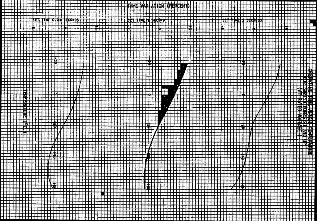
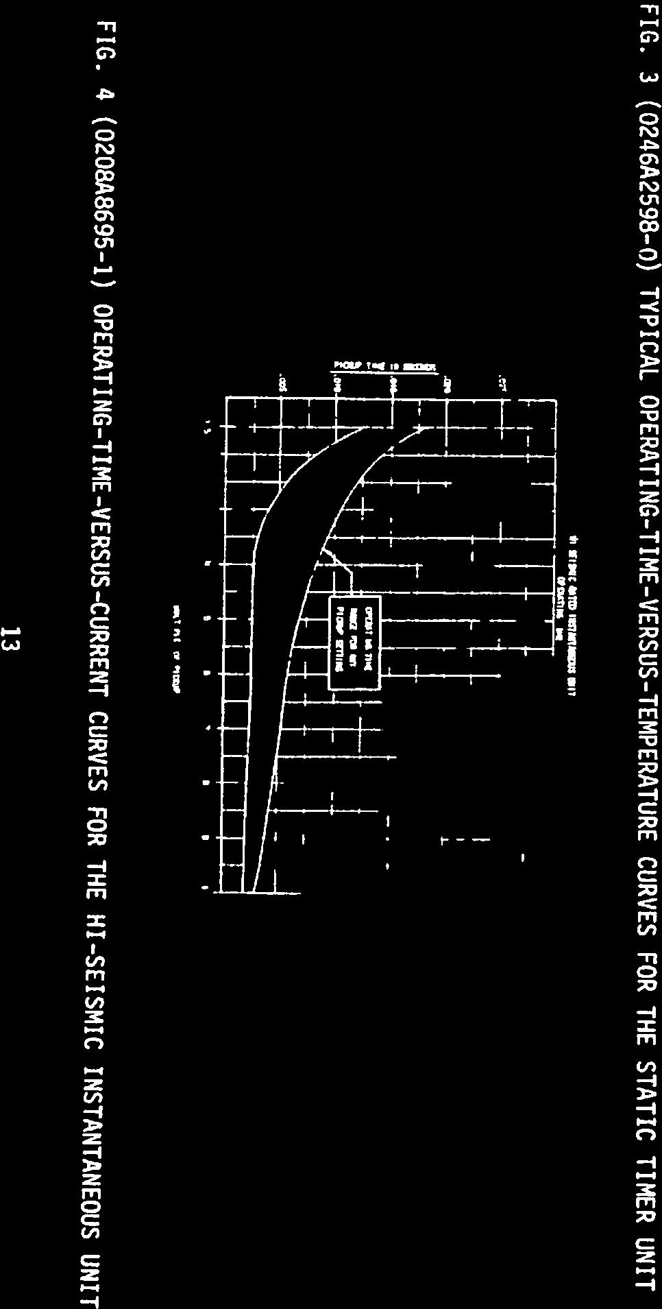
13 GEK FIG. 3 (o246a2598o) TYPICAL OPERATINGTIMEVERSUSTEMPERATURE CURVES FOR THE STATIC TIMER UNIT r I.,.;,,! II3.Jr tint Iriti,a \ I, FIG. 4 (0208A8695l) OPERATINGTIMEVERSUSCURRENT CURVES FOR THE HISEISMIC INSTANTANEOUS UNIT 13
 TRANSIENT OVERREACH OF THE HIGHDROPOUTINSTANTANEOUS UNIT I SHADING RING(D) SLEEVE(C) LOCKNUT(B) ADJUSTABLE CORE (A) FIG.")
14 13= CURRENT SUDDENLY APPLIED. A PICKUP CURRENT GRADUALlY APPITED. PENCENT OVEN.REACH 100 LA ffm THILPJ TRANSIENT OVERREACH JINC NEIAY (INSTNTANEcXJS EL.IENT) 14 FIG. 6 (O195A49501) TRANSIENT OVERREACH OF THE HIGHDROPOUTINSTANTANEOUS UNIT I SHADING RING(D) SLEEVE(C) LOCKNUT(B) ADJUSTABLE CORE (A) FIG. 5 ( ) CONSTRUCTION OF THE HIGHDROPOUTINSTANTANEOUS UNIT 1l U I 11 HI II I 4 I H LW I LII í II H III a 10 I 20 II I [ I T T I ll I i1iwll: L r I) 4 1j LH..11 GE K jc
15 GEK45344 (PHOTO NOT AVAILABLE) FIG. 7 ( ) IAC66S RELAY FRONT VIEW WITHOUT THE DRAWOUT CASE (PHOTO NOT AVAILABLE) FIG. 8 ( ) IAC66S RELAY REAR VIEW WITHOUT THE DRAWOUT CASE 15
 CONSTRUCTION OF STATICTIMEROUTPUT UNIT COIL TERMINALS,COIt SCREW )RESIDUAL SCREW COIL RETAINING AR MATURE")
 OUTLINE AND PANEL DRILLING DIMENSIONS FOR THE 1AC66S RELAY ON STEEL PANELS HA)WARE FOR SURFACE LITG.")
16 16 FIG. 10 ( ) CONSTRUCTION OF STATICTIMEROUTPUT UNIT COIL TERMINALS,COIt SCREW )RESIDUAL SCREW COIL RETAINING AR MATURE ACTUATING ARM FIG. 9 (02?7A8541O) OUTLINE AND PANEL DRILLING DIMENSIONS FOR THE 1AC66S RELAY ON STEEL PANELS HA)WARE FOR SURFACE LITG. VIEW SHOWING ASSEUBLY OF UOUNTING(FRONT VIEW) I PANEL DRLLING FOR SURFACE MOUNTING (FRONT VIEW) PANEL DRILLtJG FOR SEMIFLUSH (FRONT VIEW) OUTLINE NUMBERING OF STUDS B KY ::.(0R STUD) cq 1032 SCREW PANFL LOCATION GEK45344

17 SEALiN TARGET & GEK G 17 FIG. 11 (0257A5091O) INTERNAL CONNECTIONS DIAGRAM FOR TIE IAC66S RELAY (FRONT VIEW) = PIN NO. ON TIMER P. C. CARD =LACK LEADJG & B LEADS FOR HIGH RANGE. = UPPER STUDS UNAVAILABLE DUE TO SPACE LIMI1ATIONS = SHORT FINGER = GREEN LEAD l POSITION SHOWN IS FOR LOW RANGE.INTERCHANGE =FOR INT.CONNS.OF 11MER CARD,SEE 0227A
 INTERNAL CONNECTIONS")


18 18 FIG. 12 (0227A25052) INTERNAL CONNECTIONS DIAGRAM FOR THE STATIC TIMER UNIT IN THE IAC66S RELAY aj.iponent SIDE 167 lb (4i WONENTS TO VIEW 0165B1967 G7 0165B1987 G8 5.0 OI65B22 G2 P.C. CARD A94. () CNTFJL JLTt4E POINTS P.C. CAR) GEK 45344


19 FIG. 13 ( ) CROSS SECTION OF DRAWOUT CASE CONTACT ASSEMBLY THE TERMINAL BLOCK TRAVELS 1/4 INCH BEFORE ENGAGING THE MAIN BRUSH ON NOTEAFTER ENGAGING AUXILIARY BRUSH,CONNECTING PLUG SHORTING BAR AUXILIARY BRUSH TERMINAL BLOCK CONNECTING PLUG MAIN BRUSH CONNECTING BLOCK GEK45344
 TYPICAL EXTERNAL CONNECTIONS DIAGRAM FOR IAC66S RELAY 381 3...75 GENERAL ELECTRIC CO., POWER SYSTEMS MANAGEMENT BUSINESS DEPT., MALVERN, PA. 19355")
20 GEK45344 LOAD CEN 2 3 (4 1S1ERJRI IFHASES2&3 I 1 J TIME OVERQJRRENT UNIT i_ STANDARD INSTANTANEOUS OVERCtJRRENT UNIT f HIGI DROPOUT INSTANTANEOUS OVERCIJRRENT UNIT 52 CIRCUIT BREAKER FIG. 14 (208A55963) TYPICAL EXTERNAL CONNECTIONS DIAGRAM FOR IAC66S RELAY GENERAL ELECTRIC CO., POWER SYSTEMS MANAGEMENT BUSINESS DEPT., MALVERN, PA
INSTRUCTIONS HAA 15A / 15B / 15C / 15D / 15E / 15F / 15G / 15H AUXILIARY CURRENT RELAYS
 g INSTRUCTIONS HAA 15A / 15B / 15C / 15D / 15E / 15F / 15G / 15H AUXILIARY CURRENT RELAYS Manual Part Number: GEI-83964H Copyright 2000 215 Anderson Avenue Markham, Ontario L6E 1B3 Canada Telephone: (905)
COM Overcurrent Relay
 41-102.1B COM Overcurrent Relay Figure 1: COM-5 Class 1E Relay (Front View) 9664A28 Photo Figure 2: COM-5 Class 1E Relay (Rear View) 9664A29 Photo Photo needed here 2 COM Overcurrent Relay 41-102.1B 3
INSTRUCTIONS. GEI-38974A Supersedes GEI INSTANTANEOUS CURRENT RELAY TYPE PJC2OA GENERALS ELECTRIC
 INSTRUCTIONS GEI-38974A Supersedes GEI 38974 INSTANTANEOUS CURRENT RELAY TYPE PJC2OA GENERALS ELECTRIC 2 DESCRIPTION APPLICATION MOUNTING SERVICING RENEWAL PARTS 10 PICKUP AND RESET ELECTRICAL TESTS ELECTRICAL
Type CRN-1 Reverse Power Relay 50 and 60 Hertz
 ABB Automation Inc. Substation Automation and Protection Division Coral Springs, FL 33065 Instruction Leaflet 41-251.2P Effective: June 1991 Supersedes I.L. 41-251.2N Dated April 1988 ( )Denotes Change
ABB ! CAUTION. Type KRV Directional Overcurrent Relay E 1.0 APPLICATION 2.0 CONSTRUCTION AND OPERATION. Instruction Leaflet
 ABB Instruction Leaflet 41-137.2E Effective: February 1994 Supersedes I.L. 41-137.2D, Dated February 1973 ( )Denotes Change Since Previous Issue. Type KRV Directional Before putting relays into service,
2.0 CONSTRUCTION AND OPERATION 3.0 CHARACTERISTICS K. CO (HI-LO) Overcurrent Relay
 Overcurrent Relay") 41-100K 2.0 CONSTRUCTION AND OPERATION The type CO relays consist of an overcurrent unit (CO), either an Indicating Switch (ICS) or an ac Auxiliary Switch (ACS) and an Indicating Instantaneous Trip unit
41-100K 2.0 CONSTRUCTION AND OPERATION The type CO relays consist of an overcurrent unit (CO), either an Indicating Switch (ICS) or an ac Auxiliary Switch (ACS) and an Indicating Instantaneous Trip unit
3.0 CHARACTERISTICS E Type CO-4 Step-Time Overcurrent Relay
 41-106E Type CO-4 Step-Time Overcurrent Relay A core screw accessible from the top of the switch provides the adjustable pickup range. The IIT contacts are connected in the trip circuit to trip instantaneously.
TYPE KF UNDER-FREQUENCY RELAY A. Figure 1: Type KF Relay for 60 Hertz without Case. (Front & Rear View.) Front View Rear View
 Front View Rear View") 41-503.21A TYPE KF Front View Rear View Figure 1: Type KF Relay for 60 Hertz without Case. (Front & Rear View.) 2 TYPE KF 41-503.21A lower pin bearing, which is mounted on the frame, with respect to the
41-503.21A TYPE KF Front View Rear View Figure 1: Type KF Relay for 60 Hertz without Case. (Front & Rear View.) 2 TYPE KF 41-503.21A lower pin bearing, which is mounted on the frame, with respect to the
P. Sub 4 184A404. Sub 3 876A220
 Figure 1. Type CRN-1 Relay Without Case. 1 = Directional Unit (D). 2 = Timer Unit (T). 3 = Indicating Contactor Switch (ICS). Sub 4 184A404 Sub 3 876A220 Figure 2. Internal Schematic of the Single Trip
GEK 45484B INSTRUCTIONS MULTI-CONTACT AUXILIARY RELAY HFA151 TYPE. GE Protection and Control 205 Great Valley Parkway Malvern, PA
 GEK 45484B INSTRUCTIONS MULTI-CONTACT AUXILIARY RELAY TYPE HFA151 GE Protection and Control 25 Great Valley Parkway Malvern, PA 19355-1337 GEK 45484 CONTENTS PAGE DESCRIPTION 3 APPLICATION 3 RATINGS 3
INSTRUCTIONS GEI-98305C UNDERVOLTAGE RELAY D-C. Type NGV18A GENERAL ELECTRIC
 INSTRUCTIONS GEI-98305C D-C UNDERVOLTAGE RELAY Type NGV18A GENERAL ELECTRIC 2 Fig (8035275) NOV18A Relay Removed From Case (Rear View) GEI-98305 D-C Undervoltage Relay Type NOV Fig. 1 (8035274) NGVI&L
ABB. Type CRQ Directional Negative Sequence Relay for Ground Protection B 1.0 APPLICATION 2.0 CONSTRUCTION AND OPERATION CAUTION
 ABB Instruction Leaflet 41-163.2B Effective: January 1977 Supersedes I.L. 41-137.3A, Dated September 1974 ( ) Denotes Change Since Previous Issue Type CRQ Directional Negative Sequence Relay for Ground
A - Add New Information C - Change Existing Information D - Delete Information. Page 7. Delete the fourth paragraph beginning CAUTION
 ABB Effective: November 1990 This Addendum Supersedes all Previous Addenda Addendum to Instruction Leaflet 41-137.3H Type KRD-4 Directional Overcurrent Ground Relay A - Add New Information C - Change Existing
GEK41931B INSTRUCTIONS MULTI-CONTACT AUXILIARY RELAYS TYPE HFA73K. GE Protection and Control 205 Great Valley Parkway Malvern, PA
 GEK41931B INSTRUCTIONS MULTI-CONTACT AUXILIARY RELAYS TYPE HFA73K GE Protection and Control 205 Great Valley Parkway Malvern, PA 19355-1337 GEK-41931 CONTENTS PAGE DESCRIPTION 3 APPLICATION 3 TABLE I 3
B CW POWER RELAY
 41-241.31B CW POWER RELAY nected in such a way that current, (I A ), leads voltage, (V BA ), by 150 degrees when the motor is operating at unity power factor. Loss of excitation to the motor causes a large
C. Figure 1. CA-16 Front View Figure 2. CA-16 Rear View
 Figure 1. CA-16 Front View Figure 2. CA-16 Rear View 2 2.1. Restraint Elements Each restraint element consists of an E laminated electromagnet with two primary coils and a secondary coil on its center
L. Photo. Figure 2: Types CA-16 Relay (rear view) Photo. Figure 1: Types CA-16 Relay (front view)
 Photo. Figure 1: Types CA-16 Relay (front view)") Figure 1: Types CA-16 Relay (front view) Photo Figure 2: Types CA-16 Relay (rear view) Photo 2 Sub 5 185A419 Sub 6 185A443 Figure 3: Internal Schematic of the Type CA-16 bus Relay or CA-26 Transformer
Figure 1: Types CA-16 Relay (front view) Photo Figure 2: Types CA-16 Relay (rear view) Photo 2 Sub 5 185A419 Sub 6 185A443 Figure 3: Internal Schematic of the Type CA-16 bus Relay or CA-26 Transformer
DIAC DIFC DSFC Digital Self Powered Overcurrent Protection
 GEK 070B GE Power Management DIAC DIFC DSFC Digital Self Powered Overcurrent Protection *(RZHU0DQDJHPHQW $QGHUVRQ$YHQXH 0DUNKDPQWDULR &DQDGD/% ZZZJHFRPLQGV\VSP TABLE OF CONTENTS INTRODUCTION... PRODUCT
ABB Automation Inc. Substation Automation and Protection Division Coral Springs, FL 33065
 ABB Automation Inc. Substation Automation and Protection Division Coral Springs, FL 33065 Instruction Leaflet Effective: October 1999 Supersedes I.L. 41-133R, Dated August 1998 ( ) Denotes Changed Since
Figure 1. Type CWP-1 Ground Relay (Front View) Figure 2. Type CWP-1 Ground Relay (Rear View) E
 Figure 2. Type CWP-1 Ground Relay (Rear View) E") Figure 1. Type CWP-1 Ground Relay (Front View) Figure 2. Type CWP-1 Ground Relay (Rear View) 41-242.5E 2 Typical 60 Hertz time product curves for the type CWP-1 relay are shown in Figure 4 with 100 volts
Figure 1. Type CWP-1 Ground Relay (Front View) Figure 2. Type CWP-1 Ground Relay (Rear View) 41-242.5E 2 Typical 60 Hertz time product curves for the type CWP-1 relay are shown in Figure 4 with 100 volts
4.0 OPERATION Type ITH-T Relay
 41-771.2 Type ITH-T Relay 3.3 OPERATION INDICATOR This operation indicator is a small solenoid coil connected in the trip circuit. When the coil is energized a spring-restrained armature releases the white
INSTRUCTIONS SYNCHRONISM-CHECK RELAYS. GE Meter and Control. 205 Great Valley Parkway Malvern, PA Types IJS51A.
 INSTRUCTIONS and hjs52a Types IJS51A J CLO%NG - -* RELAY GENERALtEL1CTRjC SYNCHRONISM-CHECK RELAYS 205 Great Valley Parkway Malvern, PA 19355-07 15 GE Meter and Control GEl! 1791? INSTALLATION PROCEDURE
INSTRUCTIONS. GE Protection and Control. 205 Great Valley Parkway Malvern, PA UNDERVOL TAGE RELAYS TYPES: IAV54E IAV55C IAV54F IAV55F
 INSTRUCTIONS GEH-1768G IAV5 411 IAV5 511 IAV5 5J IAV54F IAV55F IAV54E IAV55C TYPES: UNDERVOL TAGE RELAYS 25 Great Valley Parkway Malvern, PA 19355-1337 GE Protection and Control GEIL 1768 RESET B LiTTON
ABB Automation, Inc. Substation Automation & Protection Division Coral Springs, FL Allentown, PA
 ABB Automation, Inc. Substation Automation & Protection Division Coral Springs, FL Allentown, PA Instruction Leaflet I.L. 41-661.1B Effective: June 1997 Supersedes I.L. 41-661.1A, Dated February 1994 Type
INSTRUCTIONS HAA 15A/15B/15C/15D/15E/15F/15G/15H AUXILIARY CURRENT RELAYS. Iso9ooo. GE Power Management
 0 INSTRUCTIONS HAA 15A/15B/15C/15D/15E/15F/15G/15H AUXILIARY CURRENT RELAYS Manual Part Number: GEI-83964H Copyright 2000 215 Anderson Avenue Markham, Ontario L6E 1B3 Canada Telephone: (905) 294-6222 Fax:
INSTRUCT IONS GEH-1 793J INSTANTANEOUS AUXILIARY RELAY TYPES HGA11A, C, H, J, K, P, S, T, V, W, X GENERAL ELECTRIC AUILIARV P A GENERALS ELECTRIC
 GENERALS ELECTRIC AUILIARV P A GENERAL ELECTRIC HGA11A, C, H, J, K, P, S, T, V, W, X TYPES INSTANTANEOUS AUXILIARY RELAY 0 INSTRUCT IONS GEH-1 793J 2 RENEWAL PARTS 8 CONTACT CLEANING 8 PERIODIC CHECKS
INSTRUCTIONS. GE Protection and Control. 205 Great Valley Parkway Malvern, PA GEK-49826D INSTANTANEOUS OVERCURRENT RELAYS TYPES:
 205 Great Valley Parkway Malvern, PA 19355-1337 GE Protection and Control HFC21B, HFC22B, HFC23C TYPES: INSTANTANEOUS OVERCURRENT RELAYS INSTRUCTIONS GEK-49826D GEK-49826 CONTENTS PAGE DESCRIPTION APPLICATION
THERMAL OVER CURRENT RELAY
 INSTRUCTIONS THERMAL OVER CURRENT RELAY Type TMCllA GEI-28826A GENERAL. ELECTRIC www. ElectricalPartManuals. com com GEI-28826A 2 Model Frequency 12TMC11A51A 50/60 12TMC11A52A 50/60 12TMC11A53A 50j60 12TMC11A54A
41-747G. Figure 1: Type DGF Relay without case (Photo)
") Figure 1: Type DGF Relay without case (Photo) 2 183A113 EDSK 205342 Figure 2: Internal Schematic of the Type DGF Relay in the FT21 Case. When a ground appears in the generator field, the dc milliammeter
Figure 1: Type DGF Relay without case (Photo) 2 183A113 EDSK 205342 Figure 2: Internal Schematic of the Type DGF Relay in the FT21 Case. When a ground appears in the generator field, the dc milliammeter
HGA. Hinged Armature Auxiliary. Hinged armature auxiliary relay to perform auxiliary functions in AC and DC circuits.
 HA Hinged Armature Auxiliary Hinged armature auxiliary relay to perform auxiliary functions in and circuits. eatures and Benefits Molded case with 4 mounting options Drawout case available Applications
INSTRUCTION S GEK 7354J AUXILIARY VOLTAGE RELAY TYPE HAA16B, HAA16C GENERAL ELECTRIC
 GENERAL ELECTRIC AUXILIARY VOLTAGE RELAY TYPE HAA16B, HAA16C INSTRUCTION S GEK 7354J EK 73 54 FIG. 1 (838617) RELAY TYPE HA16fl TN CASE (FRONT VIEW) FIG. 2 (8938618) RELAY TYPE HAA16B REMOVCr) FPOM C?S
ABB Power T&D Company Inc. Relay Division Coral Springs, FL Allentown, PA. Non-Directional, Single Phase Adjustable Time Delay Device No.
 September, 1990 Supersedes Descriptive Bulletin 41-100, pages 1-4, dated June, 1989 Mailed to: E, D, C/41-100A Hi-Lo co induction-disc type overcurrent relays are activated when the current in them exceeds
Test Cabinet (Inspection Box) Instructions. for Testing Accessories on Manually and Electrically Operated EntelliGuard G Low Voltage Circuit Breakers
 Instructions. for Testing Accessories on Manually and Electrically Operated EntelliGuard G Low Voltage Circuit Breakers") DEH41480 Test Cabinet (Inspection Box) for Testing Accessories on Manually and Electrically Operated EntelliGuard G Low Voltage Circuit Breakers Instructions 1 Table of Contents Section 1. Introduction
DEH41480 Test Cabinet (Inspection Box) for Testing Accessories on Manually and Electrically Operated EntelliGuard G Low Voltage Circuit Breakers Instructions 1 Table of Contents Section 1. Introduction
Installation Sheet January, 2016 Supersedes February, 2013
 s Installation Sheet January, 016 Supersedes February, 013 E87010-A0104-T003-A6-CLM0 Lighting and Heating Contactor 30 Amp, 3, 4, 5 Pole Magnetically Latched Description Magnetically latched CLM lighting
2.0 CONSTRUCTION 3.0 OPERATION. SA-1 Generator Differential Relay - Class 1E 2.5 TRIP CIRCUIT
 41-348.11C SA-1 Generator Differential Relay - Class 1E 2.0 CONSTRUCTION The type SA-1 relay consists of: Restraint Circuit Sensing Circuit Trip Circuit Surge Protection Circuit Operating Circuit Amplifier
3. OPERATION 2.1. RESTRAINT CIRCUIT 2.6. INDICATING CIRCUIT 2.2. OPERATING CIRCUIT 2.7. SURGE PROTECTION CIRCUIT 2.3.
 41-348.1H Type SA-1 2.1. RESTRAINT CIRCUIT The restraint circuit of each phase consists of a center-tapped transformer, a resistor, and a full wave rectifier bridge. The outputs of all the rectifiers are
GE CONSUMER & INDUSTRIAL
 GE CONSUMER & INDUSTRIAL GE POWER/VAC MANUAL GROUND AND TEST DEVICE Types PVV-1200/2000-10 PVV-3000-10 PVV-1200-20 PVV-2000-20 PVV-1200/2000-20 PVV-3000-20 PVV-1200/2000/3000-20 Instruction Number GEK-86125B
www. ElectricalPartManuals. com MAGNETIC TIME RELAYS GENERAL. ELECTRIC INSTRUCTIONS *IC *Also identified with prefix CR instead of IC.
 NSTRUCTONS MAGNETC TME RELAYS *C2820-054 *Also identified with prefix CR instead of C. GENERAL. ELECTRC GEH-85F NTRODUCTON The CR2820-054 relay is a d-e operated relay. t may be applied as an instantaneous
ADDITIONAL INFORMATION. BE1-50/51B SELF POWERED TIME OVERCURRENT RELAY and RETROFIT KITS. FEATURES and APPLICATION Page 2
 BE1-50/51B SELF POWERED TIME OVERCURRENT RELAY and RETROFIT KITS BE1-50/51B in S1 Case BE1-50/51B-219, 226 BE1-50/51B-214, 225, 230 - IAC Retrofits CO Retrofit BE1-50/51B-229 (not shown) SFC Retrofit The
SURE-TRIP OEM RELACEMENT TRIP UNIT
 RMS CURRENT MEASUREMENT with SURE-TRIP OEM RELACEMENT TRIP UNIT Update Circuit Breaker Solid State Controls with SURE-TRIP LOGIC The SURE-TRIP Solid State Tripping Systems Have Been Designed, Tested And
INSTRUCTIONS. GE Protection and Control 205 Great Valley Parkway Malvern, PA GLK 34117G
 GLK 34117G INSTRUCTIONS POLYPHASE POWER DIRECTIONAL RELAY FOR ANTI I4OTORING PROTECTION TYPE GGP53C GE Protection and Control 205 Great Valley Parkway Malvern, PA 19355-1337 PAGE CONTENTS 2 TOP UNIT 10
BE1-50/51B with S1 Case or FT-11 sized Case and Cover For non-retrofit applications, see Product Bulletin UHD.
 BE1-50/51B SELF POWERED TIME OVERCURRENT RELAY RETROFIT KITS BE1-50/51B with S1 Case or FT-11 sized Case and Cover For non-retrofit applications, see Product Bulletin UHD. BE1-50/51B, CO Retrofits BE1-50/51B,
INSTRUCTIONS. seconds. the tween the end of the bearing screw and the. top of the shaft. The moving contact is a small silver hemisphere
 . L. 41-793 NSTALLATON OPERATON MANTENANCE NSTRUCTONS TYPE CRN REVERSE POWER RELAY FOR MARNE SERVCE CAUTON Before putting relays into service remove all blocking which may have been inserted for the purpose
ProTrip Conversion Kits. For GE Types AK-15, AK-25, and AKU- 25 Low-Voltage Power Circuit Breakers INTRODUCTION. DEH Installation Instructions
 DEH 40026 Installation Instructions g ProTrip Conversion Kits For GE Types AK-15, AK-25, and AKU- 25 Low-Voltage Power Circuit Breakers INTRODUCTION GE Conversion Kits are designed for upgrading existing
GENERAL ELECTRIC INSTRUCTIONS GEK- 2M42. Insert Rooklet GEH 1793 INSTANTANEOUS AUXILIARY RELAY TYPE HGA MODEL 12HGAI1E(-)A I NTRODUCT ION
A I NTRODUCT ION") PHILAO[LPHA. PA GENERAL ELECTRIC POWER SYSTEMS MANAGEMENT DEPARTMENT latter should be referred to the General Electric Co.pany. probli erlie which are not covered sufficiently for the purchasers purpose.,
PHILAO[LPHA. PA GENERAL ELECTRIC POWER SYSTEMS MANAGEMENT DEPARTMENT latter should be referred to the General Electric Co.pany. probli erlie which are not covered sufficiently for the purchasers purpose.,
Medium Voltage Standby non-paralleling Control GUIDE FORM SPECIFICATION
 Medium Voltage Standby non-paralleling Control 1. GENERAL GUIDE FORM SPECIFICATION A. The requirements of the contract, Division 1, and part 16 apply to work in this section. 1.01 SECTIONS INCLUDE A. Medium
Low Voltage WavePro TM and EntelliGuard TM Circuit Breakers Remote Racking Operator
 GE Consumer & Industrial Electrical Distribution Operation & Maintenance Manual GEK-99986 Catalog # WPEGRRLV 115 VAC, 60/50 Hz Low Voltage WavePro TM and EntelliGuard TM Circuit Breakers Remote Racking
SURE TRIP RETRO KITS
 RMS CURRENT MEASUREMENT with SURE TRIP RETRO KITS Circuit Breaker Solid State Controls with SURE TRIP LOGIC The Sure Trip Solid State Tripping Systems Have Been Designed, Tested And Produced To all Applicable
Installation Sheet January, 2016 Supersedes June 2013
 s Installation Sheet January, 016 Supersedes June 01 E87010-A0105-T00-A6-CLM0 Lighting and Heating Contactor 60, 100, 00 Amp,, 4, 5 Pole Magnetically Latched Description Magnetically latched CLM lighting
Operation and Maintenance Manual
 DEH-41482 GE Energy Industrial Solutions Low Voltage Switchgear Remote Racking Operator For AKR Circuit Breakers Cat. # AKREGRR 115 VAC, 60/50 Hertz Operation and Maintenance Manual TABLE OF CONTENTS Section
Data Bulletin. Ground-Censor Ground-Fault Protection System Type GC Class 931
 Data Bulletin 0931DB0101 July 2001 Cedar Rapids, IA, USA Ground-Censor Ground-Fault Protection System Type GC Class 931 09313063 GT Sensor Shunt Trip of Circuit Interrupter Window Area for Conductors GC
Type SOQ Negative Sequence Time Overcurrent Relay
 ABB Power T&D Company Inc. Power Automation & Protection Division Coral Springs, FL Allentown, PA April 1998 Supersedes DB dated August 1991 Mailed to: E,D, C/41-100B For Protection of Rotating Machinery
SL-6 & SL-6A. I UNION SWITCH & SIGNAL l[ml 645 Russell Street Batesburg, SC Service Manual Field and Shop Maintenance
 I UNION SWITCH & SIGNAL l[ml 645 Russell Street Batesburg, SC 29006 Service Manual 3011 SL-6 & SL-6A Outlying Switch Lock Field and Shop Maintenance April, 1979 A-79-500-1496-3 1979, Union Switch & Signal
CR193 Vacuum Limitamp* Contactors
 GE Electrical Distribution GEH-5306C Maintenance Instructions CR193 Vacuum Limitamp* Contactors Contents Section 1 Introduction... 3 General... 3 Section 2 Description... 4 Principle of Operation... 4
Digitrip Retrofit System for ITE K-3000, K-3000 S, K-4000 and K-4000 S Breakers
 Supersedes IL 33-858-4 Dated 05/02 Digitrip Retrofit System for ITE K-3000, K-3000 S, K-4000 and K-4000 S Breakers Digitrip Retrofit System for ITE K-3000, Digitrip Retrofit System for ITE K-3000, K-3000
TRINETICS CSD SERIES OIL SWITCH INSTALLATION INSTRUCTIONS
 TRINETICS CSD SERIES OIL SWITCH INSTALLATION INSTRUCTIONS 33220900 DECEMBER 2011 Caution: The equipment covered by these installation instructions should be installed and serviced only by properly trained
UNION SERVICE SPECIFICATION NUMBER SU A
 UNION SERVICE SPECIFICATION NUMBER SU-1862 -A UNION SWITCH & SIGNJU,.,... SWISSVALE, PAe DIVISION OF WESTINGHOUSE AIR BRAKE COMPANY DN-10 TRAIN CONTROL SPECIAL SLOW DROP-AWAY RELAYS ********************
INSTRUCTIONS GEK G HIGH-SPEED DIFFERENTIAL RELAYS TYPES CFD22A AND CFD22B. GE Protection and Control
 INSTRUCTIONS GEK-341 24G TYPES CFD22A AND CFD22B HIGH-SPEED DIFFERENTIAL RELAYS 205 Great Valley Parkway Malvern, PA 19355-1337 GE Protection and Control GEK-341 24 CONTENTS PAGE APPLICATION 3 RATINGS
UBC Technical Guidelines Section Edition Commissioning of Electrical Systems Page 1 of 5
 Page 1 of 5 1.0 GENERAL 1.1 Coordination Requirements.1 UBC Building Operations Electrical Technical Support.2 UBC Energy & Water Services 2.0 REQUIREMENTS FOR COMMISSIONING AND TESTING 2.1 Testing.1 Unit
INSTRUCTIONS TIME OVERCURRENT RELAY TYPE IAC 12IAC77S(-)A INTRODUCTION
A INTRODUCTION") GEK- 27936A INSERT BOOKLET GEH-2059 INSTRUCTIONS TIME OVERCURRENT RELAY TYPE IAC MODEL 12IAC77S(-)A INTRODUCTION This supplements in conjunction with GEH-2059, forms the instructions for relay model 121AC77S(-)A.
GEK- 27936A INSERT BOOKLET GEH-2059 INSTRUCTIONS TIME OVERCURRENT RELAY TYPE IAC MODEL 12IAC77S(-)A INTRODUCTION This supplements in conjunction with GEH-2059, forms the instructions for relay model 121AC77S(-)A.
INSTRUCTIONS GEI-10190L DC AUXILIARY RELAYS TYPE HGA17A TO F, H, M, R, S, T GENERAL ELECTRIC
 GENERAL ELECTRIC TYPE HGA17A TO F, H, M, R, S, T DC AUXILIARY RELAYS INSTRUCTIONS GEI-10190L RATINGS 3 CHARACTERISTICS a DESCRIPTION 3 CONTENTS PAGE BURDENS 4 CONSTRUCTION 4 LOCATION AND MOUNTING S MAINTENANCE
TABLE I 60 CYCLE BURDEN OF THE CVD RELAY AT CONTINUOUS RATING
 the voltage unit contacts, this effect is negligible. 3.2 Trip Circuit The main contacts will close 30 amperes at 250 volts dc and the seal-in contacts of the indicating contactor switch (ICS) will carry
INSTRUCTIONS GEH 2056F POWER RELAYS. Types ICW51A ICW52A ICW52B GENERALJ ELECTRIC
 GENERALJ ELECTRIC ICW51A ICW52B ICW52A Types POWER RELAYS GEH 2056F INSTRUCTIONS CONTENTS DESCRIPTION 3 APPLICATION 3 RATINGS 4 CONTACTS 4 CHARACTERISTICS 5 OPERATING PRINCIPLES 5 PICK-UP 5 OPERATING AND
feeder Vibratory feeder
 VM-3155C Installation, Operation and Maintenance Instructions Vibratory feeder model hs36 Vibratory feeder model 36C ERIEZ MAGNETICS HEADQUARTERS: 2200 ASBURY ROAD, ERIE, PA 16506 1402 U.S.A. WORLD AUTHORITY
GENERAL ELECTRIC INSTRUCTIONS. GE I Supersedes GEI-28802E INSTANTANEOUS VOLTAGE RELAYS TYPES
 INSTRUCTIONS GE I -288021 Supersedes GEI-28802E INSTANTANEOUS VOLTAGE RELAYS TYPES PJV11J PJV11AL PJV11AZ PJV11L PJV1IAM PJV1IBF PJV11N PJV11AN PJV12B PJV11AF PJV11AR PJV12C PJV11AH PJV11AS PJV14B PJV11AJ
Installation, Operation and Maintenance Instructions
 VM-3153B Installation, Operation and Maintenance Instructions Vibratory feeder model 26C ERIEZ MAGNETICS HEADQUARTERS: 2200 ASBURY ROAD, ERIE, PA 16506 1402 U.S.A. WORLD AUTHORITY IN ADVANCED TECHNOLOGY
Type CDG 14 Extremely Inverse Time Overcurrent and Earth Fault Relay
 Type DG 14 Extremely Inverse Time Overcurrent and Earth Fault Relay Type DG 14 Extremely Inverse Time Overcurrent and Earth Fault Relay DG 14 drawn out from the case The type DG 14 relay is a heavily damped
DESIGN GUIDELINES LOW VOLTAGE SWITCHGEAR PAGE 1 of 5
 DESIGN GUIDELINES LOW VOLTAGE SWITCHGEAR PAGE 1 of 5 1.1. APPLICABLE PUBLICATIONS 1.1.1. Publications listed below (including amendments, addenda, revisions, supplements, and errata), form a part of this
Instructions for A200, A210, A250 size 6, two- or three-pole non-reversing or reversing motor controllers
 Instruction Leaflet IL0330300E Supersedes I.L. 7055C, Pages 8, Dated June 998 Instructions for A00, A0, A50 size 6, two- or three-pole non-reversing or reversing motor controllers Contents Description
PROCESS ELECTRONICS CORPORATION
 MINIVERTER MANUAL PROCESS ELECTRONICS CORPORATION 100 BRICKYARD ROAD MOUNT HOLLY, NORTH CAROLINA 28120 TELEPHONE (800) 421-9107 FAX (704) 827-9595 SALES@PECRECTIFIER.COM WWW.PECRECTIFIER.COM SOLID STATE
80 Series 4 Post Brake Instructions
 Bulletin No. BK4604 (12/01) 80 Series 4 Post Brake Instructions Read carefully before attempting to assemble, install, operate or maintain the product described. Protect yourself and others by observing
Vacuum Circuit Breaker Type VAD-3
 Instruction Bulletin Bulletin 6055-11 Vacuum Circuit Breaker Type VAD-3 4.76 kv, 29 ka (250 MVA) 4.76 kv, 41 ka (350 MVA) 8.25 kv, 33 ka (500 MVA) 15.0 kv, 18 ka (500 MVA) 15.0 kv, 28 ka (750 MVA) 15,0
Vacuum Circuit Breakers (Vehicle)
") Vacuum Circuit Breakers (Vehicle) Type 5 HVR 4.16kV Instructions Installation Operation Maintenance SGIM-9948D Hazardous voltages and high-speed moving parts. Will cause death, serious injury or equipment
Vacuum Circuit Breakers (Vehicle) Type 5 HVR 4.16kV Instructions Installation Operation Maintenance SGIM-9948D Hazardous voltages and high-speed moving parts. Will cause death, serious injury or equipment
SecoVac * Ground & Test Device
 GE Industrial Solutions DEH-50007 Installation, Operation and Maintenance Manual SecoVac * Ground & Test Device For 5kV-15kV IEEE Metal-clad Switchgear Table of Contents 1. Introduction...6 Safety Precautions...6
DIRACT BRAKES 70 SERIES 4 POST BRAKE INSTRUCTIONS
 Bulletin No. BK4605 (3/18) DIRACT BRAKES 70 SERIES 4 POST BRAKE INSTRUCTIONS IMPORTANT Read this bulletin carefully before installing or operating this brake. Failure to comply with these instructions
INSTRUCTION MANUAL. Type SWF. Sine Wave Filters 480 Volts, 60Hz. Page 1 of 14. April 15, 2010: updated capacitor UL File number)
") POWER QUALITY INSTRUCTION MANUAL Type SWF Sine Wave Filters 480 Volts, 60Hz April 15, 2010: updated capacitor UL File number) Page 1 of 14 Contents 1. Introduction & SAFETY 2. Theory of operation 3. Advantage
POWER QUALITY INSTRUCTION MANUAL Type SWF Sine Wave Filters 480 Volts, 60Hz April 15, 2010: updated capacitor UL File number) Page 1 of 14 Contents 1. Introduction & SAFETY 2. Theory of operation 3. Advantage
www. ElectricalPartManuals. com INSTRUCTIONS "INERTEEN AND OIL INSULATED FEEDER SWITCHES DESCRIPTION INSTALLATION MAINTENANCE
 r \ FIG. 1. Cutaway View of Typical Switch. I.L. 46-723-1 DESCRIPTION INSTALLATION MAINTENANCE INSTRUCTIONS THE INERTEEN AND OIL INSULATED FEEDER SWITCH provides complete switching facilities in a minimum
GEK 41880D INSTRUCTIONS MACHINE FIELD GROUND DETECTOR RELAY TYPE PJG12B. GE Protection and Control. 205 Great Valley Parkway Malvern, PA
 25 Great Valley Parkway Malvern, PA 19355-1337 GE Protection and Control TYPE PJG12B MACHINE FIELD GROUND DETECTOR RELAY INSTRUCTIONS GEK 4188D GEK-41 88 CONTENTS PAGE DESCRIPTION 3 APPLICATION 3 RATINGS
A. Submit manufacturer's literature and technical data before starting work.
 SECTION 16425 SWITCHBOARD PART 1 GENERAL 1.01 SUMMARY A. Related Section: 1. 16450 - Grounding. 1.02 SUBMITTALS A. Submit manufacturer's literature and technical data before starting work. B. Submit Shop
Control Relays Overview
 Control Relays Overview DESIGN FEATURES Among the advances Agastat Control Relays offer over existing designs is a unique contact operating mechanism. An articulated arm assembly amplifies the movement
1. Take the cover off the relay, taking care to not shake or jar the relay or other relays around it.
 RC SCOPE This test procedure covers the testing and maintenance of Westinghouse RC relays. The Westinghouse Protective Relay Division was purchased by ABB, and new relays carry the ABB label. Refer to
CONTROLLIX CORPORATION CONTROLLIX.COM LOW VOLTAGE AUTOMATIC SWITCH CAPACITOR BANK SPECIFICATIONS
 LOW VOLTAGE AUTOMATIC SWITCH CAPACITOR BANK SPECIFICATIONS I. SCOPE a. This specification describes the necessary requirements for the design, fabrication, and operation of automatically switched, low
A system fault contribution of 750 mva shall be used when determining the required interrupting rating for unit substation equipment.
 General Unit substations shall be 500 kva minimum, 1500 kva maximum unless approved otherwise by the University. For the required configuration of University substations see Standard Electrical Detail
www. ElectricalPartManuals. com INSTRUCTIONS TYPE CO CONTACT MAKING AMMETER INSTALLATION OPERATION MAINTENANCE I.. L APPLICATION
 l.. L. 41-109 NSTALLATON OPERATON MANTENANCE NSTRUCTONS TYPE CO CONTACT MAKNG AMMETER CAUTON Before putting relays into service, remove all blocking inserted for the purpose of securing the parts during
Vacuum Circuit Breakers (Vehicle) Type HKR 7.5kV to 15kV. Instructions Installation Operation Maintenance SGIM-9928C
 Type HKR 7.5kV to 15kV. Instructions Installation Operation Maintenance SGIM-9928C") Vacuum Circuit Breakers (Vehicle) Type HKR 7.5kV to 15kV Instructions Installation Operation Maintenance SGIM-9928C Hazardous voltages and high-speed moving parts. Will cause death, serious injury or equipment
Vacuum Circuit Breakers (Vehicle) Type HKR 7.5kV to 15kV Instructions Installation Operation Maintenance SGIM-9928C Hazardous voltages and high-speed moving parts. Will cause death, serious injury or equipment
INSTRUCTION INFORMATION FOR TYPE "DB" ELECTRIC DISC BRAKE (DB-0, DB-2, DB-4)
") The Last Word in Cranes INSTRUCTION INFORMATION FOR TYPE "DB" ELECTRIC DISC BRAKE (DB-0, DB-2, DB-4) OPERATION Zenar's type "DB" brakes are classified as a holding or parking type electro-mechanical operated
The Last Word in Cranes INSTRUCTION INFORMATION FOR TYPE "DB" ELECTRIC DISC BRAKE (DB-0, DB-2, DB-4) OPERATION Zenar's type "DB" brakes are classified as a holding or parking type electro-mechanical operated
Horizontal Circuit Switchers
 > Transformer Protection > CIRCUIT SWITCHERS C A T A L O G B U L L E T I N General Application Southern States Types CSH and CSH-B Horizontal Circuit Switchers provide an economical, versatile, space saving
Horizontal Circuit Switchers
 > Transformer Protection > CIRCUIT SWITCHERS C A T A L O G B U L L E T I N General Application Southern States Types CSH and CSH-B Horizontal Circuit Switchers provide an economical, versatile, space saving
SECTION MICROPROCESSOR TRIP UNITS FOR LV CIRCUIT BREAKERS. This section is organized as indicated below. Select desired Paragraphs.
 SECTION 16904 MICROPROCESSOR TRIP UNITS FOR LV CIRCUIT BREAKERS PART 2 PRODUCTS 01 MANUFACTURERS A. B. C. Eaton * * The listing of specific manufacturers above does not imply acceptance of their products
INSTRUCTION MANUAL. I/P Converter DSG BXXY3Z DSG BXXY4Z
 INSTRUCTION MANUAL I/P Converter DSG BXXY3Z DSG BXXY4Z Revision 2.0 3.626 016136 en Page 1/15 Should you have any questions concerning the I/P converter, please contact the Service Department of the Product
Florham Park, NJ USA Call (ASCO) for sales or service
 for sales or service") Operator s Manual 7000 Series ATS Automatic Transfer Switches D design, 30 through 230 A DANGER is used in this manual to warn of a hazard situation which, if not avoided, will result in death or serious
Operator s Manual 7000 Series ATS Automatic Transfer Switches D design, 30 through 230 A DANGER is used in this manual to warn of a hazard situation which, if not avoided, will result in death or serious
SALDET SALES & SERVICE, INC. CLINTON TOWNSHIP, MICHIGAN
 Form 1254 BRAKETRON Electronic Motor Brake Instructions SALDET SALES & SERVICE, INC. CLINTON TOWNSHIP, MICHIGAN TABLE OF CONTENTS SECTION TITLE PAGE I. Introduction 1 II. Specifications 1 III. Principles
Instructions for De-Ion Air Circuit Breakers Types DM2R, DM2F
 Instructions for De-Ion Air Circuit s Types DM2R, DM2F (Formerly Westinghouse Electric Corporation) 820 Washington Boulevard Pittsburgh, PA 15206 E-Mail: sales@homewoodsales.com Website: www.homewoodsales.com
Michigan State University Construction Standards SECONDARY UNIT SUBSTATIONS PAGE
 PAGE 261116-1 SECTION 261116 PART 1 - GENERAL 1.1 RELATED DOCUMENTS A. Drawings and general provisions of the Contract, including General and Supplementary Conditions and Division 01 Specification Sections,
Installation, Operation and Maintenance Instructions
 VM-3154B Installation, Operation and Maintenance Instructions Vibratory feeder model hs36 ERIEZ MAGNETICS HEADQUARTERS: 2200 ASBURY ROAD, ERIE, PA 16506 1440 U.S.A. WORLD AUTHORITY IN ADVANCED TECHNOLOGY
Vacuum Circuit Breaker (Vehicle)
") Vacuum Circuit Breaker (Vehicle) Type 5 HVU-250 4.76kV Instructions Installation Operation Maintenance SGIM-9998A Hazardous voltages and high-speed moving parts. Will cause death, serious injury or equipment
Vacuum Circuit Breaker (Vehicle) Type 5 HVU-250 4.76kV Instructions Installation Operation Maintenance SGIM-9998A Hazardous voltages and high-speed moving parts. Will cause death, serious injury or equipment
Product Specifications for Phase Over Phase GOABS(r)
") 1. General a) This specification covers the design, manufacture, and shipment of phase-over-phase, 1-way, 2-way, 3-way, and 4-way, gang-operated disconnecting switches, both air-break and load-break, for
1. General a) This specification covers the design, manufacture, and shipment of phase-over-phase, 1-way, 2-way, 3-way, and 4-way, gang-operated disconnecting switches, both air-break and load-break, for
ichards MANUFACTURING COMPANY, SALES, INC. 517 LYONS AVENUE, IRVINGTON, NJ Phone Fax
 Network Protector Instruction Manual Type 137NP 800 to 3500 Amperes ichards MANUFACTURING COMPANY, SALES, INC. 517 LYONS AVENUE, IRVINGTON, NJ 07111 Phone 973-371-1771 Fax 973-371-9538 IM 1224-001B DISCLAIMER
Service Instructions. Syntron Light-Capacity Electromagnetic Model: F-T01-A DF-T01-A
 Service Instructions Syntron Light-Capacity Electromagnetic Model: F-T01-A DF-T01-A Service Instructions Syntron Light-Capacity Electromagnetic Vibrating Feeders Models: F-T01-A and DF-T01-A Contents Page
Syntron EB-00 Vibratory Parts Feeder GENERAL MANUAL
 Syntron EB-00 Vibratory Parts Feeder GENERAL MANUAL INSTALLATION OPERATION MAINTENANCE Thank you for buying your equipment from Homer City Automation Inc. This manual will help you to understand how your