MODEL 05305L WIND MONITOR-AQ WITH
|
|
|
- Austen Stafford
- 5 years ago
- Views:
Transcription

1 MODEL 05305L WIND MONITOR-AQ WITH 4-20mA OUTPUTS JULY 1998 MANUAL PN 05305L-90 Page 1

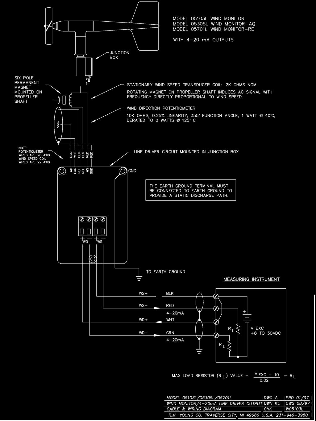
2 MODEL 05305L WIND MONITOR-AQ 4-20mA OUTPUTS GENERAL Power Requirement: 8-30 VDC Operating Temperature: -50 to 50 C (-58 to 122 F) INTRODUCTION The Wind Monitor measures horizontal wind speed and direction. Developed for air quality applications, it is accurate, sensitive, and corrosion resistant. The main housing, nose cone, propeller, and other internal parts are injection molded U.V. stabilized plastic. The tail section is lightweight expanded polystyrene. Both the propeller and vertical shafts use stainless steel precision grade ball bearings. Bearings have shields to help exclude contamination and moisture. Propeller rotation produces an AC sine wave signal with frequency proportional to wind speed. Internal circuitry converts the raw signal to 4 to 20 ma current output over specified wind speed range. Vane position is sensed by a 10K ohm precision conductive plastic potentiometer. This signal is also converted to 4 to 20mA output. WIND SPEED SPECIFICATION SUMMARY The instrument mounts directly on a standard one inch pipe, outside diameter 34 mm (1.34"). An orientation ring is provided so the instrument can be removed for maintenance and re-installed without loss of wind direction reference. Both the sensor and the orientation ring are secured to the mounting pipe by stainless steel band clamps. Electrical connections are made in a junction box at the base. Range Sensor Distance Constant Threshold Sensitivity Transducer Output Signal Model No. Suffix M P N K 0 to 40 m/s (90 mph), gust survival 100 m/s (220 mph) 20 cm diameter 4-blade helicoid carbon fiber thermoplastic propeller, 30.7 cm air passage per revolution 2.1 m (6.9 ft.) for 63% recovery 0.4 m/s (0.9 mph) Centrally mounted stationary coil, 2K Ohm nominal DC resistance 4 to 20 ma over specified wind speed range Range 0 to 50 M/S 0 to 100 MPH 0 to 100 KNOTS 0 to 200 KILOMETERS/HOUR WIND DIRECTION (AZIMUTH) SPECIFICATION SUMMARY Range 360 mechanical, 355 electrical (5 open) Sensor Balanced vane, 48.3 cm (19 in) turning radius. Damping Ratio 0.45 Delay Distance 1.2 m (3.9 ft) for 50% recovery Threshold Sensitivity 0.5 m/s (1.0 mph) at 10 displacement Damped Natural Wavelength 4.9 m (16.1 ft) Undamped Natural Wavelength 4.4 m (14.4 ft) Transducer Precision conductive plastic potentiometer, 10K ohm resistance (±20%), 0.25% linearity, life expectancy 50 million revolutions, rated 1 watt at 40 C, 0 watts at 125 C Output Signal 4 to 20 ma for 0 to 360 Page 1 INITIAL CHECK-OUT When the Wind Monitor is unpacked it should be checked carefully for any signs of shipping damage. Remove the plastic nut on the propeller shaft. Install the propeller on the shaft with the serial number of the propeller facing forward (into the wind). The instrument is aligned, balanced and fully calibrated before shipment; however, it should be checked both mechanically and electrically before installation. The vane and propeller should easily rotate 360 without friction. Check vane balance by holding the instrument base so the vane surface is horizontal. It should have near neutral torque without any particular tendency to rotate. A slight imbalance will not degrade performance. INSTALLATION Proper placement of the instrument is very important. Eddies from trees, buildings, or other structures can greatly influence wind speed and wind direction observations. To get meaningful data for most applications, locate the instrument well above or upwind from obstructions. As a general rule, the air flow around a structure is disturbed to twice the height of the structure upwind, six times the height downwind, and up to twice the height of the structure above ground. For some applications it may not be practical or necessary to meet these requirements. FAILURE TO PROPERLY GROUND THE WIND MONITOR MAY RESULT IN ERRONEOUS SIGNALS OR TRANSDUCER DAMAGE. Grounding the Wind Monitor is vitally important. Without proper grounding, static electrical charge can build up during certain atmospheric conditions and discharge through the transducers. This discharge may cause erroneous signals or transducer failure.
3 To direct the discharge away from the transducers, the mounting post assembly in which the transducers are mounted is made with a special anti-static plastic. It is important that the mounting post be connected to a good earth ground. There are two ways this may be accomplished. First, the Wind Monitor may be mounted on a metal pipe which is connected to earth ground. The mounting pipe should not be painted where the Wind Monitor is mounted. Towers or masts set in concrete should be connected to one or more grounding rods. If it is difficult to ground the mounting post in this manner, the following method should be used. Inside the junction box the screw labeled EARTH GND is internally connected to the anti-static mounting post. This terminal should be connected to an earth ground (Refer to wiring diagram). Initial installation is most easily done with two people; one to adjust the instrument position and the other to observe the indicating device. After initial installation, the instrument can be removed and returned to its mounting without re-aligning the vane since the orientation ring preserves the wind direction reference. Install the Wind Monitor following these steps: 1. MOUNT WIND MONITOR a) Place orientation ring on mounting post. Do Not tighten band clamp yet. Orientation ring may be omitted when portable tripod is used. b) Place Wind Monitor on mounting post. Do Not tighten band clamp yet. 2. CONNECT SENSOR CABLE. a) Refer to wiring diagram located at back of manual. 3. ALIGN VANE a) Connect instrument to indicator. b) Choose a known wind direction reference point on the horizon. c) Sighting down instrument centerline, point nose cone at reference point on horizon. d) While holding vane in position, slowly turn base until indicator shows proper value. e) Tighten mounting post band clamp. f ) Engage orientation ring indexing pin in notch at instrument base. g) Tighten orientation ring band clamp. CALIBRATION The Wind Monitor is fully calibrated before shipment and should require no adjustments. Recalibration may be necessary after some maintenance operations. Periodic calibration checks are desirable and may be necessary where the instrument is used in programs which require auditing of sensor performance. Accurate wind direction calibration requires a Model Vane Angle Bench Stand. Begin by connecting the instrument to a signal conditioning circuit which has some method of indicating the wind direction value. This may be a display which shows wind direction values in angular degrees or simply a voltmeter monitoring the output. Orient the base so the junction box faces due south. Visually align the vane with the crossmarkings and observe the indicator output. If the vane position and indicator do not agree within 5, it may be necessary to adjust the potentiometer coupling inside the main housing. Details for making this adjustment appear in the MAINTENANCE, POTENTIOMETER REPLACEMENT, outline, step 7. It is important to note that while the sensor mechanically rotates through 360, full scale wind direction signal from the signal conditioning occurs at 355. The signal conditioning electronics must be adjusted accordingly. For example, in a circuit where 4 to 20 ma represents 0 to 360, the output must be adjusted for 19.8 ma when the instrument is at 355. [((355 /360 ) x 16 ma) + 4 ma]. Wind speed calibration is determined by propeller pitch and the output characteristics of the transducer. Calibration formulas showing wind speed vs. propeller rpm and output frequency are included below. Standard accuracy is ± 0.2 m/s (0.4 mph). For greater accuracy, the sensor must be individually calibrated in comparison with a wind speed standard. Contact the factory or your supplier to schedule a NIST (National Institute of Standards & Technology) traceable wind tunnel calibration in our facility. To calibrate wind system electronics, temporarily remove the propeller and connect an Anemometer Drive to the propeller shaft. Apply the calibration formula to the calibrating motor rpm and adjust the electronics for the proper value. For example, with the propeller shaft turning at 3600 rpm adjust an indicator to display 18.4 m/s [3600 rpm x (m/s)/rpm = 1.84 m/s.] Details on checking bearing torque, which affects wind speed and direction threshold, appear in the following section. CALIBRATION FORMULAS Model 05305L Wind Monitor w / Propeller WIND SPEED vs PROPELLER RPM 05305LM m/s = x rpm 05305LN knots = x rpm 05305LP mph = x rpm 05305LK km/h = x rpm WIND SPEED vs ma OUTPUT 05305LM m/s = ( x ma) LN knots = ( x ma) LP mph = ( x ma) LK km/h = ( x ma)-50 WIND DIRECTION vs ma OUTPUT DEGREES = (22.5 x ma)-90 MAINTENANCE Given proper care, the Wind Monitor should provide years of service. The only components likely to need replacement due to normal wear are the precision ball bearings and the wind direction potentiometer. Only a qualified instrument technician should perform the replacement. If service facilities are not available, return the instrument to the company. Refer to the drawings to become familiar with part names and locations. The asterisk * which appears in the following outlines is a reminder that maximum torque on all set screws is 80 oz-in. POTENTIOMETER REPLACEMENT The potentiometer has a life expectancy of fifty million revolutions. As it becomes worn, the element may begin to produce noisy signals or become non-linear. When signal noise or non-linearity becomes unacceptable, replace the potentiometer. Refer to exploded view drawing and proceed as follows: 1. REMOVE MAIN HOUSING a) Unscrew nose cone from main housing. Set o-ring aside for later use. b) Gently push main housing latch. c) While pushing latch, lift main housing up and remove it from vertical shaft bearing rotor. Page 2
4 2. UNSOLDER TRANSDUCER WIRE a) Remove junction box cover, exposing circuit board. b) Remove screws holding circuit board. c) Unsolder three potentiometer wires (white, green, black), two wind speed coil wires (red, black), and earth ground wire (red) from board. 3. REMOVE POTENTIOMETER a) Loosen set screw on potentiometer coupling and remove it from potentiometer adjust thumbwheel. b) Loosen set screw on potentiometer adjust thumbwheel and remove it from potentiometer shaft extension. c) Loosen two set screws at base of transducer assembly and remove assembly from vertical shaft. d) Unscrew potentiometer housing from potentiometer mounting & coil assembly. e) Push potentiometer out of potentiometer mounting & coil assembly by applying firm but gentle pressure on potentiometer shaft extension. f ) Loosen set screw on potentiometer shaft extension and remove it from potentiometer shaft. 4. INSTALL NEW POTENTIOMETER a) Place potentiometer shaft extension on new potentiometer (Gap 0.040") and tighten set screw*. b) Push new potentiometer into potentiometer mounting & coil assembly. c) Feed potentiometer and coil wires through hole in bottom of potentiometer housing. d) Screw potentiometer housing onto potentiometer mounting & coil assembly. Apply a small amount of silicone sealant on threads. e) Gently pull transducer wires through bottom of potentiometer housing to take up any slack. Apply a small amount of silicone sealant around hole. f ) Install transducer assembly on vertical shaft allowing 0.5 mm (0.020") clearance from vertical bearing. Tighten set screws* at bottom of transducer assembly. g) Place potentiometer adjust thumbwheel on potentiometer shaft extension and tighten set screw*. h) Place potentiometer coupling on potentiometer adjust thumbwheel. Do Not tighten set screw yet. 5. RECONNECT TRANSDUCER WIRES a) Using needle-nose pliers or a paper clip bent to form a small hook, gently pull transducer wires through hole in junction box. b) Solder wires to circuit board according to wiring diagram. Observe color code. c) Secure circuit board in junction box using two screws removed in step 2b. Do not overtighten. 6. REPLACE MAIN HOUSING a) Place main housing over vertical shaft bearing rotor. Be careful to align indexing key and channel in these two assemblies. b) Place main housing over vertical shaft bearing rotor until potentiometer coupling is near top of main housing. c) Turn potentiometer adjust thumbwheel until potentiometer coupling is oriented to engage ridge in top of main housing. Set screw on potentiometer coupling should be facing the front opening. d) With potentiometer coupling properly oriented, continue pushing main housing onto vertical shaft bearing rotor until main housing latch locks into position with a click. 7. ALIGN VANE a) Connect excitation voltage and signal conditioning electronics to terminal strip according to wiring diagram. b) With mounting post held in position so junction box is facing due south, orient vane to a known angular reference. Details appear in CALIBRATION section. c) Reach in through front of main housing and turn potentiometer adjust thumbwheel until signal conditioning system indicates proper value. d) Tighten set screw* on potentiometer coupling. 8. REPLACE NOSE CONE a) Screw nose cone into main housing until o-ring seal is seated. Be certain threads are properly engaged to avoid cross-threading. FLANGE BEARING REPLACEMENT If anemometer bearings become noisy or wind speed threshold increases above an acceptable level, bearings may need replacement. Check anemometer bearing condition using a Model Propeller Torque Disc. If necessary, bearings are replaced as follows. 1. REMOVE OLD BEARINGS a) Unscrew nose cone. Set o-ring aside for later use. b) Loosen set screw on magnet shaft collar and remove magnet. c) Slide propeller shaft out of nose cone assembly. d) Remove front bearing cap which covers front bearing. e) Remove both front and rear bearings from nose cone assembly. Insert edge of a pocket knife under bearing flange and lift it out. 2. INSTALL NEW BEARINGS a) Insert new front and rear bearings into nose cone. b) Replace front bearing cap. c) Carefully slide propeller shaft thru bearings. d) Place magnet on propeller shaft allowing 0.5 mm (0.020") clearance from rear bearing. e) Tighten set screw* on magnet shaft collar. f ) Screw nose cone into main housing until o-ring seal is seated. Be certain threads are properly engaged to avoid cross-threading. VERTICAL SHAFT BEARING REPLACEMENT Vertical shaft bearings are much larger than the anemometer bearings. Ordinarily, these bearings will require replacement less frequently than anemometer bearings. Check bearing condition using a Model Vane Torque Gauge. Since this procedure is similar to POTENTIOMETER REPLACEMENT, only the major steps are listed here. 1. REMOVE MAIN HOUSING. 2. UNSOLDER TRANSDUCER WIRES AND REMOVE TRANSDUCER ASSEMBLY. Loosen set screws at base of transducer assembly and remove entire assembly from vertical shaft. 3. REMOVE VERTICAL SHAFT BEARING ROTOR by sliding it upward off vertical shaft. 4. REMOVE OLD VERTICAL BEARINGS AND INSTALL NEW BEARINGS. When inserting new bearings, be careful not to apply pressure to bearing shields. 5. REPLACE VERTICAL SHAFT BEARING ROTOR. 6. REPLACE TRANSDUCER & RECONNECT WIRES. 7. REPLACE MAIN HOUSING. 8. ALIGN VANE. 9. REPLACE NOSE CONE. *Max set screw torque 80 oz-in Page 3
5 WARRANTY This product is warranted to be free of defects in materials and construction for a period of 12 months from date of initial purchase. Liability is limited to repair or replacement of defective item. A copy of the warranty policy may be obtained from R. M. Young Company. CE COMPLIANCE This product has been tested and shown to comply with European CE requirements for the EMC Directive. Please note that shielded cable must be used. Declaration of Conformity Application of Council Directives: 89/336/EEC Standards to which Conformity is Declared: EN (IEC 801-2, 3, 4) Manufacturer's Name and Address: R. M. Young Company Traverse City, MI, 49686, USA Importer's Name and Address: See Shipper or Invoice Type of Equipment: Meteorological Instruments Model Number / Year of Manufacture: 05305L/1996 I, the undersigned, hereby declare that the equipment specified conforms to the above Directives and Standards. Date / Place: Traverse City, Michigan, USA January 8, 1996 David Poinsett R & D Manager, R. M. Young Company Page 4
6

7
8

9
MARCH 2002 MANUAL PN 05103L-90
 MODEL 05103L WIND MONITOR WITH 4-20mA OUTPUTS MARCH 2002 MANUAL PN 05103L-90 MODEL 05103L WIND MONITOR 4-20mA OUTPUTS GENERAL Power Requirement: 8-30 VDC Operating Temperature: -50 to 50 C (-58 to 122
METEOROLOGICAL INSTRUMENTS
 METEOROLOGICAL INSTRUMENTS INSTRUCTIONS WIND SENTRY MODEL 03002L R.M. YOUNG COMPANY 2801 AERO PARK DRIVE, TRAVERSE CITY, MICHIGAN 49686, USA TEL: (231) 946-3980 FAX: (231) 946-4772 WEB: www.youngusa.com
METEOROLOGICAL INSTRUMENTS
 METEOROLOGICAL INSTRUMENTS INSTRUCTIONS WIND MONITOR WITH VOLTAGE OUTPUTS MODEL 05103V R.M. YOUNG COMPANY 2801 AERO PARK DRIVE, TRAVERSE CITY, MICHIGAN 49686, USA TEL: (231) 946-3980 FAX: (231) 946-4772
METEOROLOGICAL INSTRUMENTS
 METEOROLOGICAL INSTRUMENTS INSTRUCTIONS WIND MONITOR 4-20mA OUTPUTS MODEL 05103L(KMNP) R.M. YOUNG COMPANY 2801 AERO PARK DRIVE, TRAVERSE CITY, MICHIGAN 49686, USA TEL: (231) 946-3980 FAX: (231) 946-4772
METEOROLOGICAL INSTRUMENTS
 METEOROLOGICAL INSTRUMENTS INSTRUCTIONS WIND SENTRY MODEL 03002 R.M. YOUNG COMPANY 2801 AERO PARK DRIVE, TRAVERSE CITY, MICHIGAN 49686, USA TEL: (231) 946-3980 FAX: (231) 946-4772 WEB: www.youngusa.com
METEOROLOGICAL INSTRUMENTS
 METEOROLOGICAL INSTRUMENTS INSTRUCTIONS WIND SENTRY MODEL 03002-5 R.M. YOUNG COMPANY 2801 AERO PARK DRIVE, TRAVERSE CITY, MICHIGAN 49686, USA TEL: (231) 946-3980 FAX: (231) 946-4772 WEB: www.youngusa.com
METEOROLOGICAL INSTRUMENTS
 METEOROLOGICAL INSTRUMENTS INSTRUCTIONS WIND MONITOR MODEL 05103V-45 R.M. YOUNG COMPANY 2801 AERO PARK DRIVE, TRAVERSE CITY, MICHIGAN 49686, USA TEL: (231) 946-3980 FAX: (231) 946-4772 WEB: www.youngusa.com
METEOROLOGICAL INSTRUMENTS
 METEOROLOGICAL INSTRUMENTS INSTRUCTIONS WIND MONITOR WITH 4-20 ma OUTPUTS MODEL 05103L R.M. YOUNG COMPANY 2801 AERO PARK DRIVE, TRAVERSE CITY, MICHIGAN 49686, USA TEL: (231) 946-3980 FAX: (231) 946-4772
METEOROLOGICAL INSTRUMENTS
 METEOROLOGICAL INSTRUMENTS INSTRUCTIONS WIND MONITOR-AQ MODEL 05305 R.M. YOUNG COMPANY 2801 AERO PARK DRIVE, TRAVERSE CITY, MICHIGAN 49686, USA TEL: (231) 946-3980 FAX: (231) 946-4772 WEB: www.youngusa.com
METEOROLOGICAL INSTRUMENTS
 METEOROLOGICAL INSTRUMENTS INSTRUCTIONS WIND MONITOR-MA MARINE MODEL MODEL 05106 R.M. YOUNG COMPANY 2801 AERO PARK DRIVE, TRAVERSE CITY, MICHIGAN 49686, USA TEL: (231) 946-3980 FAX: (231) 946-4772 WEB:
METEOROLOGICAL INSTRUMENTS
 METEOROLOGICAL INSTRUMENTS INSTRUCTIONS WIND MONITOR MODEL 05103 R.M. YOUNG COMPANY 2801 AERO PARK DRIVE, TRAVERSE CITY, MICHIGAN 49686, USA TEL: (231) 946-3980 FAX: (231) 946-4772 WEB: www.youngusa.com
METEOROLOGICAL INSTRUMENTS
 METEOROLOGICAL INSTRUMENTS INSTRUCTIONS WIND MONITOR-HD ALPINE MODEL 05108-45 R.M. YOUNG COMPANY 2801 AERO PARK DRIVE, TRAVERSE CITY, MICHIGAN 49686, USA TEL: (231) 946-3980 FAX: (231) 946-4772 WEB: www.youngusa.com
MODEL 12002/12005 GILL MICROVANE & 3-CUP ANEMOMETER MODEL GILL 3-CUP ANEMOMETER MODEL 12302/12305 GILL MICROVANE APRIL 1994
 MODEL 12002/12005 GILL MICROVANE & 3-CUP ANEMOMETER MODEL 12102 GILL 3-CUP ANEMOMETER MODEL 12302/12305 GILL MICROVANE APRIL 1994 MANUAL PN 12002/12005-90 R. M. YOUNG COMPANY 2801 AERO PARK DRIVE, TRAVERSE
METEOROLOGICAL INSTRUMENTS
 METEOROLOGICAL INSTRUMENTS INSTRUCTIONS WIND MONITOR-MA MARINE MODEL MODEL 05106 R.M. YOUNG COMPANY 2801 AERO PARK DRIVE, TRAVERSE CITY, MICHIGAN 49686, USA TEL: (231) 946-3980 FAX: (231) 946-4772 WEB:
METEOROLOGICAL INSTRUMENTS
 METEOROLOGICAL INSTRUMENTS INSTRUCTIONS WIND MONITOR-HD MODEL 05108 R.M. YOUNG COMPANY 2801 AERO PARK DRIVE, TRAVERSE CITY, MICHIGAN 49686, USA TEL: (231) 946-3980 FAX: (231) 946-4772 WEB: www.youngusa.com
MODEL 27106T GILL PROPELLER ANEMOMETER
 MODEL 27106T GILL PROPELLER ANEMOMETER REV: B030106 MANUAL PN: R. M. YOUNG COMPANY 2801 AERO PARK DRIVE, TRAVERSE CITY, MICHIGAN 49686, USA TEL: (231) 946-3980 FAX: (231) 946-4772 MODEL 27106T GILL PROPELLER
METEOROLOGICAL INSTRUMENTS
 METEOROLOGICAL INSTRUMENTS INSTRUCTIONS GILL PROPELLER ANEMOMETER MODEL 27106D R.M. YOUNG COMPANY 2801 AERO PARK DRIVE, TRAVERSE CITY, MICHIGAN 49686, USA TEL: (231) 946-3980 FAX: (231) 946-4772 WEB: www.youngusa.com
METEOROLOGICAL INSTRUMENTS
 METEOROLOGICAL INSTRUMENTS INSTRUCTIONS WIND MONITOR - SE MODEL 09101 R.M. YOUNG COMPANY 2801 AERO PARK DRIVE, TRAVERSE CITY, MICHIGAN 49686, USA TEL: (231) 946-3980 FAX: (231) 946-4772 WEB: www.youngusa.com
METEOROLOGICAL INSTRUMENTS
 METEOROLOGICAL INSTRUMENTS INSTRUCTIONS PROPELLER ANEMOMETER MODEL 27106T R.M. YOUNG COMPANY 2801 AERO PARK DRIVE, TRAVERSE CITY, MICHIGAN 49686, USA TEL: (231) 946-3980 FAX: (231) 946-4772 WEB: www.youngusa.com
METEOROLOGICAL INSTRUMENTS
 METEOROLOGICAL INSTRUMENTS INSTRUCTIONS WIND MONITOR-SE-MA MODEL 09106 R.M. YOUNG COMPANY 2801 AERO PARK DRIVE, TRAVERSE CITY, MICHIGAN 49686, USA TEL: (231) 946-3980 FAX: (231) 946-4772 WEB: www.youngusa.com
MODEL 27106DT GILL PROPELLER ANEMOMETER JANUARY 2003 MANUAL PN 27106DT-90 R. M. YOUNG COMPANY
 MODEL 27106DT GILL PROPELLER ANEMOMETER JANUARY 2003 MANUAL PN 27106DT-90 R. M. YOUNG COMPANY 2801 AERO PARK DRIVE, TRAVERSE CITY, MICHIGAN 49686, USA TEL: (231) 946-3980 FAX: (231) 946-4772 MODEL 27106DT
METEOROLOGICAL INSTRUMENTS
 METEOROLOGICAL INSTRUMENTS INSTRUCTIONS WIND MONITOR - SE MODEL 09101 R.M. YOUNG COMPANY 2801 AERO PARK DRIVE, TRAVERSE CITY, MICHIGAN 49686, USA TEL: (231) 946-3980 FAX: (231) 946-4772 WEB: www.youngusa.com
METEOROLOGICAL INSTRUMENTS
 METEOROLOGICAL INSTRUMENTS INSTRUCTIONS PRECIPITATION GAUGE MODEL 50202 / 50203 R.M. YOUNG COMPANY 2801 AERO PARK DRIVE, TRAVERSE CITY, MICHIGAN 49686, USA TEL: (231) 946-3980 FAX: (231) 946-4772 WEB:
METEOROLOGICAL INSTRUMENTS
 METEOROLOGICAL INSTRUMENTS INSTRUCTIONS COMPACT ASPIRATED RADIATION SHIELD MODEL 43502 R.M. YOUNG COMPANY 2801 AERO PARK DRIVE, TRAVERSE CITY, MICHIGAN 49686, USA TEL: (231) 946-3980 FAX: (231) 946-4772
Wind Direction Vane. Z345. Installation Guide.
 Wind Direction Vane. Z345 Installation Guide. Wind Direction Vane Installation Guide Index. Description. 3 Features. 3 Ordering Information. 3 Specifications. 3 Product Liability. 3 Connection & Wiring.
NOVALYNX CORPORATION MODEL 200-WS-02F WIND SPEED & DIRECTION SENSOR INSTRUCTION MANUAL
 NOVALYNX CORPORATION MODEL 200-WS-02F WIND SPEED & DIRECTION SENSOR INSTRUCTION MANUAL REVISION DATE: MAY 2005 Receiving and Unpacking Carefully unpack all components and compare to the packing list. Notify
SENSORS CLIMATRONICS CORPORATION (631) MANUAL - F460 WIND DIRECTION SENSOR P/N M Rev C. Figure 1. Figure 2
 MANUAL - F460 WIND DIRECTION SENSOR P/N M Rev C. Figure 1. Figure 2") SENSORS MANUAL - F460 WIND DIRECTION SENSOR P/N M100076 Rev C U1.0 INTRODUCTION Climatronics F460 Wind Direction Sensor, P/N 100076, is designed to provide low starting threshold, fast dynamic response
SENSORS MANUAL - F460 WIND DIRECTION SENSOR P/N M100076 Rev C U1.0 INTRODUCTION Climatronics F460 Wind Direction Sensor, P/N 100076, is designed to provide low starting threshold, fast dynamic response
Micro Response Anemometer Model User s Manual National Drive Sacramento, CA
 Micro Response Anemometer Model 2030 User s Manual 1165 National Drive Sacramento, CA 95834 800.824.5873 Introduction The Model 2030 Micro Response Anemometer is a highly responsive three cup anemometer
Wind Speed/Direction Smart Sensor (Part # S-WCA-M003)
") (Part # S-WCA-M003) The Wind Speed/Direction smart sensor is designed to work with the HOBO Stations. The smart sensor has a plug-in modular connector that allows it to be added easily to a HOBO Station.
(Part # S-WCA-M003) The Wind Speed/Direction smart sensor is designed to work with the HOBO Stations. The smart sensor has a plug-in modular connector that allows it to be added easily to a HOBO Station.
USER'S GUIDE. Combined Wind Sensor WMS301 and WMS302. M210375en-A
 USER'S GUIDE Combined Wind Sensor WMS301 and WMS302 M210375en-A PUBLISHED BY Vaisala Oyj Phone (int.):+358 9 8949 1 P.O. Box 26 Fax: +358 9 8949 2227 FIN-00421 Helsinki Finland Visit our Internet pages
ANEMOMETER Vaisala WAA252
 ANEMOMETER Vaisala WAA252 SIGNAL OUTPUT ELECTRICAL SUPPLY HEATING SUPPLY MODEL IN EOL MANAGER 0...750 Hz square wave 5...15 VDC 10mA typ. 24 VDC
HDI inch Choke Position Indicator User s Manual Rev Indicator Gauge Linear Potentiometer
 HDI 2522 4-inch Choke Position Indicator User s Manual Rev 2 New 2522 Indicator Gauge Linear Potentiometer w/open Housing 2200 Indicator Gauge Linear Potentiometer TABLE OF CONTENTS HDI 2522 4-inch Indicator
70 Series 8700 Coupler 2-pc Hub & Shaft Three Phase Brake Instructions IP43 & IP56 (NEMA 2 & 4) Housing
 Housing") Bulletin No. BK4775-3 (08/2016) 70 Series 8700 Coupler 2-pc Hub & Shaft Three Phase Brake Instructions IP43 & IP56 (NEMA 2 & 4) Housing Read carefully before attempting to assemble, install, operate or
Bulletin No. BK4775-3 (08/2016) 70 Series 8700 Coupler 2-pc Hub & Shaft Three Phase Brake Instructions IP43 & IP56 (NEMA 2 & 4) Housing Read carefully before attempting to assemble, install, operate or
Wind direction sensors. User s manual
 Cod. MW6020 Wind direction sensors User s manual Updated 07/30/2013 INSTUM_00222 Page 1/10 Index 1 Description... 3 1.1 Main features... 3 1.2 Models and technical specifications... 3 1.2.1 Standard sensor...
Operating & Installation Manual
 Operating & Installation Manual (ZH1.5kw wind turbine system) Company Name:YUEQING ZONHAN WINDPOWER CO.,LTD. Address:NO.195,Chengxi Road,Yuecheng,Yueqing,Zhejiang,P.R.China Zip Code:325600 Tel:86-577-62529820
Flex Tube. User guide
 Flex Tube User guide CONTENTS INTRODUCTION...2 Welcome 2 Safety 2 INSTALLATION...3 Flex Tube orientation 3 Bending a Flex Tube 4 Cutting a Flex Tube 4 Connection and mounting kits 5 Feed cable kit 5 End
Maintenance Information
 Form 16575334 Edition 1 April 2005 Electric Screwdrivers EL, EP and ET 34V DC Series Maintenance Information Save These Instructions WARNING Maintenance procedures have the potential for severe shock hazard
60 Series End-Mount Brake Instructions Standard Housing
 Bulletin No. BK4655 (04/18) 60 Series End-Mount Brake Instructions Standard Housing Read carefully before attempting to assemble, install, operate or maintain the product described. Protect yourself and
70 Series 8700 End Mount Three Phase Brake Instructions IP43 (NEMA 2) Housing
 Housing") Bulletin No. BK4772S-3 (6/2017) 70 Series 8700 End Mount Three Phase Brake Instructions IP43 (NEMA 2) Housing Read carefully before attempting to assemble, install, operate or maintain the product described.
Bulletin No. BK4772S-3 (6/2017) 70 Series 8700 End Mount Three Phase Brake Instructions IP43 (NEMA 2) Housing Read carefully before attempting to assemble, install, operate or maintain the product described.
Wind Turbine Testing
 Wind Turbine Testing Why Test? Limited number of machines suitable for polar applications Identify the good and bad machines Identify the good and bad manufacturers Gain familiarity with the systems Decrease
Installation Instructions
 Quick-Mount Visual Instructions for Quick-Mount Visual Instructions 1. Rotate the damper to its failsafe position. If the shaft rotates counterclockwise, mount the CCW side of the actuator out. If it rotates
Installation Instructions
 Quick-Mount Visual Instructions for Mechanical Installation Quick-Mount Visual Instructions 1. Rotate the damper to its failsafe position. If the shaft rotates counterclockwise, mount the CCW side of the
Instruction Manual. Vibration Calibrators VC10 VC11 VC12 VC13
 Instruction Manual Vibration Calibrators VC10 VC11 VC12 VC13 Metra Mess- und Frequenztechnik Radebeul Meissner Str. 58 D-01445 Radebeul / Germany Tel. +49-351 8492104 Fax +49-351 8492169 Email: Info@MMF.de
70 Series 8700 End Mount Three Phase Brake Instructions IP56 (NEMA 4) Housing
 Housing") Bulletin No. BK4773-3 (08/2016) 70 Series 8700 End Mount Three Phase Brake Instructions IP56 (NEMA 4) Housing Read carefully before attempting to assemble, install, operate or maintain the product described.
Bulletin No. BK4773-3 (08/2016) 70 Series 8700 End Mount Three Phase Brake Instructions IP56 (NEMA 4) Housing Read carefully before attempting to assemble, install, operate or maintain the product described.
Switching DC Power Supply
 99 Washington Street Melrose, MA 02176 Phone 781-665-1400 Toll Free 1-800-517-8431 Visit us at www.testequipmentdepot.com Model 1693, 1694 Switching DC Power Supply INSTRUCTION MANUAL 1 Safety Summary
ALUMAREEL. Electrical Cord Reel. Model EC6 100 Model EC Operational, Maintenance and Installation Manual
 ALUMAREEL TM Electrical Cord Reel Model EC6 100 Model EC3 100 Operational, Maintenance and Installation Manual READ AND UNDERSTAND THIS MANUAL BEFORE USING THIS PRODUCT. RETAIN FOR FUTURE REFERENCE 1 P
F-4600 INLINE ULTRASONIC FLOW METER Installation and Operation Guide
 F-4600 INLINE ULTRASONIC FLOW METER Installation and Operation Guide 11451 Belcher Road South, Largo, FL 33773 USA Tel +1 (727) 447-6140 Fax +1 (727) 442-5699 1054-7 / 34405 www.onicon.com sales@onicon.com
SR MARINER WS-1 WIND SPEED METER. Installation Instructions
 SR MARINER WS-1 WIND SPEED METER Installation Instructions Congratulations in choosing a high performance marine instrument and welcome to the growing family of SR Mariner product owners. Since our establishment
4.0 OPERATION Type ITH-T Relay
 41-771.2 Type ITH-T Relay 3.3 OPERATION INDICATOR This operation indicator is a small solenoid coil connected in the trip circuit. When the coil is energized a spring-restrained armature releases the white
Weatherproof Tubular Slip Ring Assembly
 Weatherproof Tubular Slip Ring Assembly Model B8-4.3W 8 circuit weatherproof slip ring Compact design Mounts on shafts up to 4.3 [109.2 mm] in diameter Permanently lubricated bearings Rugged stainless
TOTALIZER-TRANSMITTER
 TOTALIZER-TRANSMITTER MODEL TR04-2 OPERATION AND MAINTENANCE MANUAL PARTS LIST FEATURING: *SEALED HOUSING *STANDARD TOTALIZER ASSEMBLY *MAGNETICALLY ACTUATED REED SWITCH 3255 WEST STETSON AVENUE HEMET,
CRICKET Alphasonic Level Transmitter Model LA12 Owner s Manual
 Warranty, Service and Repair To register your product with the manufacturer, fill out the enclosed warranty card and return it immediately to: FLOWLINE Inc. 10500 Humbolt Street Los Alamitos, CA 90720
3. Operating instructions: Minor 200
 1. Technical specifications 3. Operating instructions: Minor 200 Copyright 2015 by Endecotts Ltd. 13 1. Setting up Technical specifications SIEVE SHAKER MODEL: Minor 200 General Information The Minor 200
Mitsubishi Turbine: Hybrid XT Control Sensor Retrofit
 Mitsubishi Turbine: Hybrid XT Control Sensor Retrofit NIPPON ANEMOMETER TO HYBRID XT ANEMOMETER RETROFIT KIT, MITSUBISHI, NEI (9370) NIPPON YAW VANE TO HYBRID XT VANE RETROFIT KIT, MITSUBISHI, NEI (9371)
Provided by: Operating, Maintenance & Parts Manual
 Provided by: www.hoistsdirect.com TB681.qxd 11/29/2004 3:04 PM Page 1 Operating, Maintenance & Parts Manual TB603 Manually Lever Operated Chain Hoist 1100 POUNDS MAXIMUM CAPACITY (500 kg) Follow all instructions
Davis Wind Speed and Direction Smart Sensor (S-WCF-M003) Manual
 Manual") Davis Wind Speed and Direction Smart Sensor (S-WCF-M003) Manual The Davis Wind Speed and Direction smart sensor is designed to work with HOBO stations. The smart sensor has a plug-in modular connector
Davis Wind Speed and Direction Smart Sensor (S-WCF-M003) Manual The Davis Wind Speed and Direction smart sensor is designed to work with HOBO stations. The smart sensor has a plug-in modular connector
CIRRUS AIRPLANE MAINTENANCE MANUAL
 MODEL SR PASSENGER AND CREW DOORS. DESCRIPTION AND OPERATION Serials 000 thru 00: The two crew/passenger doors incorporate a flush-mount outside door handle, key-operated door lock, and a conventional
Roller Door Operator
 INSTALLATION INSTRUCTIONS AND OWNERS MANUAL Roller Door Operator IMPORTANT PLEASE READ THESE INSTRUCTIONS CAREFULLY PRIOR TO COMMENCING THE INSTALLATION OF THE OPERATOR UNIT CAUTION This Automatic Opener
LTX RF LEVEL SENSOR. Instruction Manual
 LTX RF LEVEL SENSOR Instruction Manual FOR MODELS LTX01, LTX02, LTX05 Intempco Document No: LTX - M01 Rev. 1 Issue Date: April 2005 LTX01 RF LEVEL SENSOR USER MANUAL Software Rev : Rev. Date : June 2004
Type 2000 Transducer Product Instructions
 Type 2000 Transducer Product Instructions The Type 2000 is an electro-pneumatic device that regulates an unregulated supply pressure down to an electronically-controlled output pressure. There are two
Wind Direction Transmitter First Class Low Power Device with digital output, 10 Bit serial-synchronous x0.001
 THE WORLD OF WEATHER DATA - THE WORLD OF WEATHER DATA - THE WORLD OF WEATHER DATA Instruction for Use 021535/06/07 Wind Direction Transmitter First Class Low Power Device with digital output, 10 Bit serial-synchronous
CVR-625. Compact Vibrating Rod Instruction Manual
 CVR-625 Compact Vibrating Rod Instruction Manual BinMaster: Division of Garner Industries 7201 N. 98th St., Lincoln, NE 68507 402-434-9102 email: info@binmaster.com www.binmaster.com OPERATING INSTRUCTIONS
Installation and Operating Manual
 Model u002 & u003 Installation and Operating Manual Ultrasonic Level Switch 60 Great Hill Road Naugatuck, CT 06770 ph: 203-729-6434 fax: 203-729-6696 www.innovativesensing.com Read this Manual Before Installing
MX431 Generator Automatic Voltage Regulator Operation Manual
 Generator Automatic Voltage Regulator Operation Manual Self Excited Automatic Voltage Regulator 1 1. SPECIFICATION Sensing Input Voltage Frequency 190 ~ 264 VAC Max, 1 phase, 2 wire 50 / 60 Hz, selectable
Differential Pressure Transmitter
 Specifications/Instructions Differential Pressure Transmitter General Model PY9000D is a differential pressure transmitter that uses a ceramic cantilever sensor. Deflection of the ceramic cantilever caused
Ultrasonic Two-Wire Point Level Control
 Ultrasonic Two-Wire Point Level Control General Instructions The Ultrasonic Point Level Control indicates liquid presence/absence within a sensor cavity. Two piezoelectric crystals face each other across
User Manual for the. AN-WD2 Wind Sensor. AN-WD2 UM v1.0. Delta-T Devices Ltd
 User Manual for the AN-WD2 Wind Sensor AN-WD2 UM v1.0 Delta-T Devices Ltd Notices Copyright All rights reserved. Under the copyright laws, this manual may not be copied, in whole or in part, without the
CP-9301 CP Application. Features. Applicable Literature. Electronic Actuator Drives General Instructions
 CP-90 CP-90 Electronic Drives General Instructions Application The CP-90 and CP-90 electronic actuator drives process a variable input signal from a controller to provide proportional control of an electric
Adelaide Wind Power Project Turbine T05 (AD117) IEC Edition 3.0 Measurement Report
 IEC Edition 3.0 Measurement Report") REPORT ID: 14215.01.T05.RP6 Adelaide Wind Power Project Turbine T05 (AD117) IEC 61400-11 Edition 3.0 Measurement Report Prepared for: Suncor Adelaide Wind General Partnership Inc. 2489 North Sheridan Way
REPORT ID: 14215.01.T05.RP6 Adelaide Wind Power Project Turbine T05 (AD117) IEC 61400-11 Edition 3.0 Measurement Report Prepared for: Suncor Adelaide Wind General Partnership Inc. 2489 North Sheridan Way
HM WIND TURBINE. Operation Manual. **Please read the manual carefully before using **
 HM4.0-3000 WIND TURBINE Operation Manual **Please read the manual carefully before using ** - 1 - HM4.0-3KW operation manual.doc 1. The aim of Application Use wind energy to generate electricity and charge
Electric Trolling Motor
 Electric Trolling Motor L Series User s Manual Please read and retain this manual before using product REACH RoHS TABLE OF CONTENTS Contents GENERAL INFORMATION 4 SPECIFICATIONS 4 WIRING AND BATTERY RECOMMENDATIONS
The gear boxes can be run at the same speeds as the actuator models. Do not exceed torque ratings.
 1. What is the lifting torque required? The lifting torque for a single actuator depends on the load, the worm gear ratio, type of screw (machine cut or ball screw) and the pitch of the lifting screw.
LA19 Series Ricochet Battery Powered Level Transmitter and Display
 Warranty, Service & Repair To register your product with the manufacturer, fill out the enclosed warranty card and return it immediately to: Flowline Inc. 10500 Humbolt Street Los Alamitos, CA 90720. If
Heavy Duty Miniature Quick-Change Applicator (End-Feed Type) with Mechanical or Air-Feed Systems
 with Mechanical or Air-Feed Systems") Heavy Duty Miniature Quick-Change Applicator (End-Feed Type) with Mechanical or Air-Feed Systems Instruction Sheet 408-8039 02 JUN 16 Rev G Ram Post Wire Disc Insulation Disc Insulation Crimper Stripper
Heavy Duty Miniature Quick-Change Applicator (End-Feed Type) with Mechanical or Air-Feed Systems Instruction Sheet 408-8039 02 JUN 16 Rev G Ram Post Wire Disc Insulation Disc Insulation Crimper Stripper
Hybrid XT Retrofit GE 1.5 SLE Turbines
 NRG Retrofit Kits #5388 & #5389 Authors: Technical Services TABLE OF CONTENTS SUMMARY... 3 WARNING AND NOTICES... 3 GROUNDING AND MOUNTING CONSIDERATIONS... 3 TOOLS AND MATERIALS REQUIRED... 4 Materials...
MICROGUARD 500 EXTENSION REEL TRAINING MANUAL. Greer Company. Greer Company Crane Systems 1 OF18
 MICROGUARD 500 EXTENSION REEL TRAINING MANUAL 1 OF18 TABLE OF CONTENTS MICROGUARD 500 SERIES EXTENSION REEL TRAINING MANUAL EXTENSION REEL OVERVIEW...3 REEL-OFF CABLE LAYERING...3 CHECKING THE REEL-OFF
Installation and Operating Manual
 MOTORS AND DRIVES SIGNAL ISOLATOR Accessory for BC204 Regenerative Drive Installation and Operating Manual 4/2000 MN1387 TABLE OF CONTENTS Section Page i. Safety Warning..........................................................
200 Series Flow Meters
 Proteus Industries Inc. 200 Series Flow Meters Technical Reference Manual Can we Improve? Tell our President! Can we improve our product, our support or this manual? We are committed to continuous improvement
Rheometer Calibration Fixture Instruction Manual Model 280 & 286
 Rheometer Calibration Fixture Instruction Manual Model 280 & 286 Instruction Manual Part No. 204210 Revision B Copyright 2009 Fann Instrument Company Houston, Texas, U.S.A. All rights reserved. No part
ABB. Type CRQ Directional Negative Sequence Relay for Ground Protection B 1.0 APPLICATION 2.0 CONSTRUCTION AND OPERATION CAUTION
 ABB Instruction Leaflet 41-163.2B Effective: January 1977 Supersedes I.L. 41-137.3A, Dated September 1974 ( ) Denotes Change Since Previous Issue Type CRQ Directional Negative Sequence Relay for Ground
TX900. Microwave Leakage Detector. 99 Washington Street Melrose, MA Phone Toll Free
 TX900 Microwave Leakage Detector 99 Washington Street Melrose, MA 02176 Phone 781-665-1400 Toll Free 1-800-517-8431 Visit us at www.testequipmentdepot.com Users Manual TX900 Microwave Leakage Detector
Model 616 Rotating Disk Electrode Instruction Manual
 Model 616 Rotating Disk Electrode Instruction Manual 219303 C / 1202 Printed in USA Advanced Measurement Technology, Inc. a/k/a Princeton Applied Research, a subsidiary of AMETEK, Inc. WARRANTY Princeton
RoughDeck TM FXB Flexure Base Floor Scale. Installation/Operation Manual
 RoughDeck TM FXB Flexure Base Floor Scale Installation/Operation Manual SM 32958 13 Contents 1. Introduction... 1 1.1 Scale Components... 1 1.2 Operating Requirements... 2 1.3 How Flexure Levers Work...
Defender 3000 Series Base Instruction Manual
 Defender 3000 Series Base Instruction Manual 99 Washington Street Melrose, MA 02176 Phone 781-665-1400 Toll Free 1-800-517-8431 Visit us at www.testequipmentdepot.com Compliance This product conforms to
RAYMOND EMC ENCLOSURES QUIETSHIELD OPERATION AND MAINTENANCE MANUAL
 RAYMOND EMC ENCLOSURES QUIETSHIELD OPERATION AND MAINTENANCE MANUAL JUNE 2006 Raymond EMC Enclosures QuietShield Operation and Maintenance Manual 1 TABLE OF CONTENTS 1. DESCRIPTION OF RAYMOND EMC QUIETSHIELD
MM1/MM2 INSTALLATION & MAINTENANCE INSTRUCTIONS
 MM1/MM2 INSTALLATION & MAINTENANCE INSTRUCTIONS DESCRIPTION / IDENTIFICATION The MM series proportional control valves utilize ProportionAir's unique closed loop control technology for superior control
Operation and Maintenance Manual for. Joyce/Dayton Linear Actuator Pound Capacity AC Actuator (with limit switch and potentiometer)
") Joyce/Dayton Corp. Operation and Maintenance Manual for Joyce/Dayton Linear Actuator 1500 Pound Capacity AC Actuator (with limit switch and potentiometer) WARNING! The recommendations in this manual for
Joyce/Dayton Corp. Operation and Maintenance Manual for Joyce/Dayton Linear Actuator 1500 Pound Capacity AC Actuator (with limit switch and potentiometer) WARNING! The recommendations in this manual for
VA-7450 Series. Electric Valve Actuators
 34-636- 771, Rev. D Installation Instructions VA-7450 Series Issue Date 0216 VA-7450 Series Electric Valve Actuators Applications VA-7450 Series Electric Valve Actuators provide on/off, floating, or proportional
Thermal. Dimensions Torque Rotating. Rotating Capacity lb.ft. HPS/Min. Lb-Ft
 Bulletin No. BK4755 (11/07) 1-70 Series End-Mount Brake Instructions NEMA 2 Enclosure Read carefully before attempting to assemble, install, operate or maintain the product described. Protect yourself
MODEL AMMONIA GAS SENSOR MODULE 4-20 ma
 MODEL 4101-25 AMMONIA GAS SENSOR MODULE 4-20 ma Model 4101-25 Ammonia Gas Sensor Module 4-20 ma APPLICABILITY & EFFECTIVITY This manual provides instructions for the following Sierra Monitor products:
Dodge 5 Lift Kit Thank you for choosing Rough Country Suspension for your Off Road needs.
 *1368BAG4* 1368BAG4 921368200 2014-16 2500 Dodge 5 Lift Kit Thank you for choosing Rough Country Suspension for your Off Road needs. Rough Country recommends a certified technician installs this system.
KEWTECH. KT56 digital multi function tester. Instruction manual
 KEWTECH KT56 digital multi function tester Instruction manual Contents 1 Safety Notice 1 2 Features and Principles of Measurement 3 3 Introduction 6 4 Specifications 7 5 Instrument layout 9 6 Operating
BLOCK GAUGE. user manual
 BLOCK GAUGE user manual 1.0 Index Section Title Page 1.0 Index....................... 1 2.0 Safety Summary............... 2 3.0 Introduction.................. 3 4.0 Components of the Block Gauge... 4 5.0
Electric motor testing
 Electric motor testing MOTOR (MODELS EJ4-4001 AND EJ8-4001A) 23 GENERAL INFORMATION The vehicle is equipped with a 48-volt DC, shunt-wound, reversible traction motor. The shunt-wound motor is designed
ABB ! CAUTION. Type KRV Directional Overcurrent Relay E 1.0 APPLICATION 2.0 CONSTRUCTION AND OPERATION. Instruction Leaflet
 ABB Instruction Leaflet 41-137.2E Effective: February 1994 Supersedes I.L. 41-137.2D, Dated February 1973 ( )Denotes Change Since Previous Issue. Type KRV Directional Before putting relays into service,
GPS AutoSteer System Installation Manual
 GPS AutoSteer System Installation Manual Supported Vehicles Agco Gleaner Combines R65 R66 R75 R76 PN: 602-0288-01-A LEGAL DISCLAIMER Note: Read and follow ALL instructions in this manual carefully before
REPAIR AND OVERHAUL OF AFCS ACTUATORS P/N S ; -113 (ROLL), ; -115 (PITCH), ; -117 (YAW)
, ; -115 (PITCH), ; -117 (YAW)") TECHNICAL BULLETIN 214ST-90-117 9 November 1990 Revision A, 31 May 2012 MODEL AFFECTED: SUBJECT: HELICOPTERS AFFECTED: COMPLIANCE: 214ST Helicopters REPAIR AND OVERHAUL OF AFCS ACTUATORS P/N S 214-001-540-107;
TECHNICAL BULLETIN 214ST-90-117 9 November 1990 Revision A, 31 May 2012 MODEL AFFECTED: SUBJECT: HELICOPTERS AFFECTED: COMPLIANCE: 214ST Helicopters REPAIR AND OVERHAUL OF AFCS ACTUATORS P/N S 214-001-540-107;
Peristaltic Cased Tube Pumps
 Peristaltic Cased Tube Pumps Operating Manual Verderflex Economy Version 1.0v-01/2014 Print No. 01 45, 500, 1500, 3000, 8000 Verderflex Economy 1.0v-01.2014 Version 1.0v-01/2014 Print-No. 01 Verderflex
Pressure Transmitter. Informational & Installation Manual
 Pressure Transmitter Informational & Installation Manual February 24, 2011 M374 Rev. E JOWA USA, Inc. 59 Porter Road Littleton, MA 01460 Phone: 978-486-9800 Fax: 978-486-0170 Care and Handling Our submersible
Application Guide S-652 S-65T S-522 S-462 S-402 S-352 S-275CH S-693 S-682 S-410 S-675 AUTOSOUND S SERIES SPEAKERS
 S-402 S-352 S-275CH S-652 S-65T S-522 S-462 S-693 S-682 S-410 S-675 AUTOSOUND S SERIES SPEAKERS Application Guide Please read through this manual to familiarize yourself with your new speakers. Should