Installation manual. 4 Suspension system GM Colorado / Canyon Part # Part # GM Colorado / Canyon 4 Suspension system
|
|
|
- Theodore Boyd
- 5 years ago
- Views:
Transcription

1 Part # GM Colorado / Canyon 4 Suspension system Parts list: Part # Description Qty Driver side knuckle Passenger side knuckle Front cross member Rear cross member Front lower skid plate Driver side differential relocation bracket Passenger side differential relocation bracket Front driver and passenger side sway bar relocation brackets Front driver and passenger side extended bump stops Front drive shaft spacer Front extended brake line kit 1 TCI-R26 Rear add-a-leaf s NB Hardware bag NB1 Hardware bag SL Sleeve bag INST Instruction manual (customer) INST Instruction manual (installer) 1 MIRRORHANGER Rear view mirror hanger 1 WARNINGDECAL Warning decal 1 DECAL Window sticker 1 Congratulations on your selection to purchase a Tuff Country EZ-Ride Suspension System. We at Tuff Country are proud to offer a high quality product at the industries most competitive pricing. Thank you for your confidence in us, and our product. Before installation begins, it is the customers/installers responsibility to make sure that all parts are on hand. If any parts are missing, please feel free to call one of our customer service (801) Tuff Country EZ-Ride Suspension packages (2) sets of instruction sheets with this box kit. (1) is for the installer and (1) is for the customer. The (1) for the customer has some post installation procedure literature and it is the installers responsibility to make sure that the customer receives a copy of the installation manual along with the literature. Installation manual 4 Suspension system GM Colorado / Canyon Part # sj030107rev.02 Important customer information: Tuff Country EZ-Ride Suspension highly recommends that a qualified and/or certified mechanic performs this installation. If you desire to return your vehicle to stock, it is the customers responsibility to save all stock hardware. This vehicles reaction and handling characteristics may differ from standard cars and/or trucks. Modifications to improve and/or enhance off road performance may raise the intended center of gravity. Extreme caution must be utilized when encountering driving conditions which may cause vehicle imbalance or loss of control. DRIVE SAFELY! Avoid abrupt maneuvers, such as sudden sharp turns which could cause a roll over, resulting in serious injury or death. It is the customers responsibility to make sure that a re-torque is performed on all hardware associated with this suspension system after the first 100 miles of installation. It is also the customers responsibility to do a complete re-torque after every 3000 miles or after every off road use. After the original installation, Tuff Country EZ-Ride Suspension also recommends having the alignment checked every 6 months to ensure proper tracking, proper wear on tires and front end components. Tuff Country EZ-Ride Suspension takes no responsibility for abuse, improper installation or improper suspension maintenance. It is the responsibility of the customer or the mechanic to wear safety glasses at all times when performing this installation. It is the customers/installers responsibility to read and understand all steps before installation begins. OEM manual should be used as a reference guide. Make sure to use locktite on all new and stock hardware associated with this installation. The Tuff Country EZ-Ride Suspension product safety label that is included in your kit box must be installed inside the cab in plain view of all occupants.
2 Limited lifetime warranty Notice to all Tuff Country EZ-Ride Suspension customers: It is your responsibility to keep your original sales receipt! If failure should occur on any Tuff Country EZ-Ride Suspension component, your original sales receipt must accompany the warranted unit to receive warranty. Warranty will be void if the customer can not provide the original sales receipt. Do not install a body lift in conjunction with a suspension system. If a body lift is used in conjunction with any Tuff Country EZ-Ride Suspension product, your Tuff Country EZ-Ride Suspension WARRANTY WILL BE VOID. Tuff Country Inc. ( Tuff Country ) suspension products are warranted to be free from defects in material and workmanship for life if purchased, installed and maintained on a non-commercial vehicle; otherwise, for a period of twelve (12) months, from the date of purchase and installation on a commercial vehicle, or twelve thousand (12,000) miles (which ever occurs first). Tuff Country does not warrant or make any representations concerning Tuff Country Products when not installed and used strictly in accordance with the manufacturer s instructions for such installation and operation and accordance with good installation and maintenance practices of the automotive industry. This warranty does not apply to the cosmetic finish of Tuff Country products nor to Tuff Country products which have been altered, improperly installed, maintained, used or repaired, or damaged by accident, negligence, misuse or racing. ( Racing is used in its broadest sense, and, for example, without regards to formalities in relation to prizes, competition, etc.) This warranty is void if the product is removed from the original vehicle and re-installed on that or any other vehicle. This warranty is exclusive and is in lieu of any implied warranty of merchantability, fitness for a particular purpose or other warranty of quality, whether express or implied, except the warranty of title. All implied warranties are limited to the duration of this warranty. The remedies set forth in this warranty are exclusive. This warranty excludes all labor charges or other incidental of consequential damages. Any part or product returned for warranty claim must be returned through the dealer of the distributor from whom it was purchased. Tuff Country reserves the right to examine all parts returned to it for warranty claim to determine whether or not any such part has failed because of defect in material or workmanship. The obligation of Tuff Country under this warranty shall be limited to repairing, replacing or crediting, at its option, any part or product found to be so defective. Regardless of whether any part is repaired, replaced or credited under this warranty, shipping and/or transportation charges on the return of such product must be prepaid by the customer under this warranty. Important information that needs to be read before installation begins: The stock wheels will not work in conjunction with this suspension system. New wheels with a 4.5 back spacing is required. Tuff Country recommends a 285/70/16 tire and wheel package. If larger than a 285/70 tire is installed on your vehicle in conjunction with part # 14045; Tuff Country assumes no liability and the warranty will be VOID. Also, 15 wheels will not work in conjuction wiht this suspension system. Before installation begins, Tuff Country EZ-Ride Suspension highly recommends that the installer performs a test drive on the vehicle. During the test drive, check to see if there are any uncommon sounds or vibrations. If uncommon sounds or vibrations occur on the test drive, uncommon sounds or vibrations will be enhanced once the suspension system has been installed. Tuff Country EZ-Ride Suspension highly recommends notifying the customer prior to installation to inform the customer of these issues if they exist. New longer front and rear shocks are needed after this suspension system has been installed and the front and rear shocks need to be ordered as a separate part #. If you have not already ordered your front and rear shocks, please feel free to contact Tuff Country or your local Tuff Country dealer and order your front and rear shocks. Tuff Country recommends installing a 21 fully extended nitrogen gas shock in the front and a 26 fully extended nitrogen gas shock in the rear. Torque settings: 5/ ft lbs. 3/ ft lbs. 7/ ft lbs. 1/ ft lbs. 9/ ft lbs. 5/ ft lbs. 3/ ft lbs.
3 Hardware bag 14045NB includes: Description Quantity 5 mm x 12 mm hex cap bolts 4 5 mm flat washers 4 10 mm x 40 mm bolts 4 10 mm split lock washers 4 10 mm x 26 mm sock head cap screws 4 14 mm x 50 mm bolts 4 14 mm flat washers 4 14 mm lock washers 4 3/8 x 3/4 bolts 4 3/8 x 1 bolts 2 5/16 USS flat washers 8 3/8 split lock washers 6 3/8 nylock nuts 2 7/16 x 2 bolts 2 7/16 x 2 1/2 bolts 4 3/8 USS flat washers 10 7/16 unitorque nuts 6 1/2 x 1 1/4 bolts 6 1/2 x 2 1/4 bolts 2 7/16 USS flat washers 12 1/2 unitorque nuts 8 9/16 x 3 1/2 bolts 4 1/2 USS flat washers 8 9/16 unitorque nuts 4 5/8 x 4 1/2 bolts 2 9/16 USS flat washers 4 5/8 unitorque nuts 2 Sert fitting 2 S10107 (Over size washers) 4 Special note: Before installation begins, it is the customers/installers responsibility to make sure that all parts are on hand. If any parts are missing, please feel free to call one of our customer service (801) Spherical rod end links are a precision part and require frequent cleaning and lubricating to enhance proper maximum performance. Failure to do this could cause failure of Spherical rod end links. Recommended tools selection; Cut off wheel Sawzall Torque wrench Standard socket set Standard wrench set Metric socket set Metric wrench set Tape measure Hydraulic floor jacks Hardware bag 14045NB1 includes: Description Quantity (ABS relocation brackets) 2 S10116 (Heim joints) 4 SUW-12 (1/2 harden washers) 2 PB8297 (Poly bushings) 4 PB6199 (Poly bump stops) 2 PB6052 (Poly bushings) 2 PB2456 (Poly bushings) 4 P98 (rear shock clevis mounts) 2 CB5162 (rear centering bolts) 2 516FN (5/16 fine nuts) 2 Hardware bag 14045SL includes: Description Quantity S10115 (.875 x.635 x sleeve) 2 S10117 (.750 x tapped sleeve) 2 S10118 (.750 x.510 x.310 sleeve) 4 S10123 (spacer sleeve) 2 S10124 (milled sleeve) 2
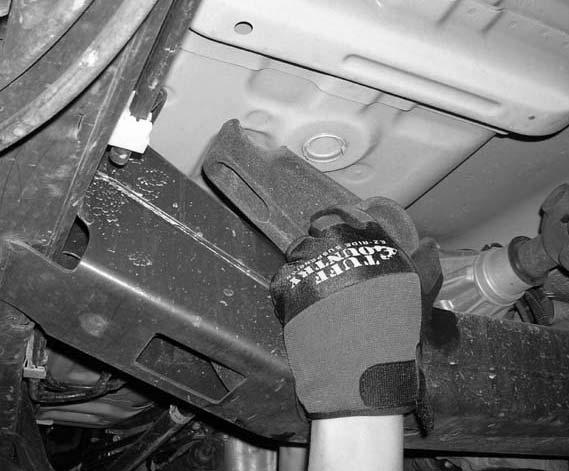
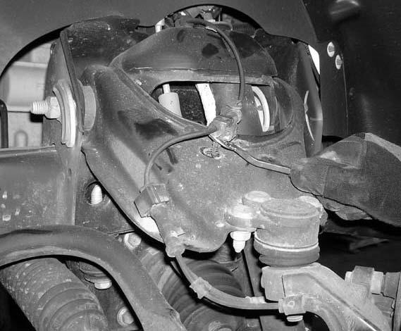
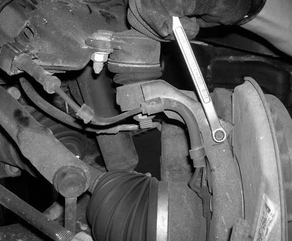
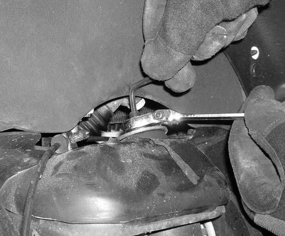
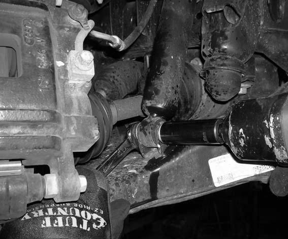
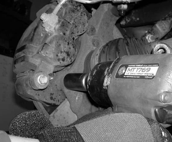
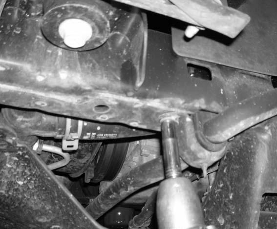
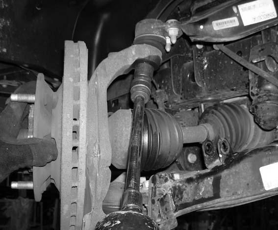
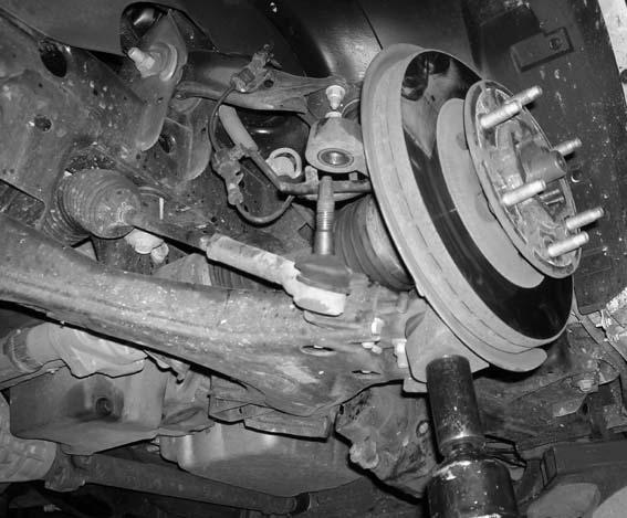
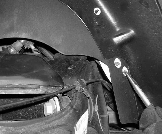
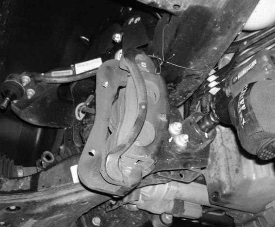
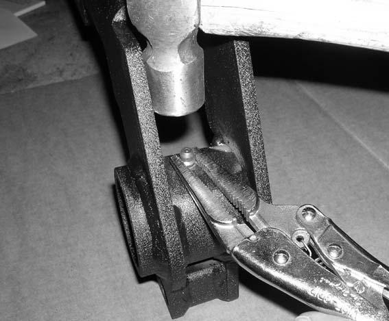
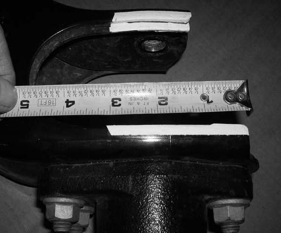
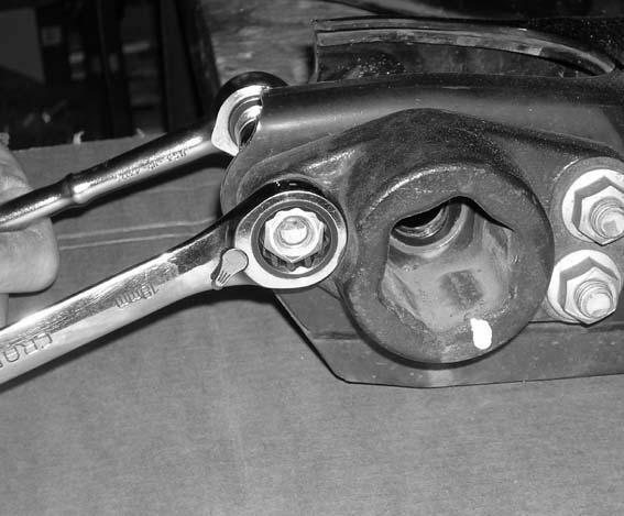
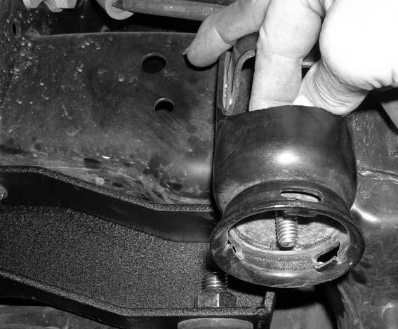
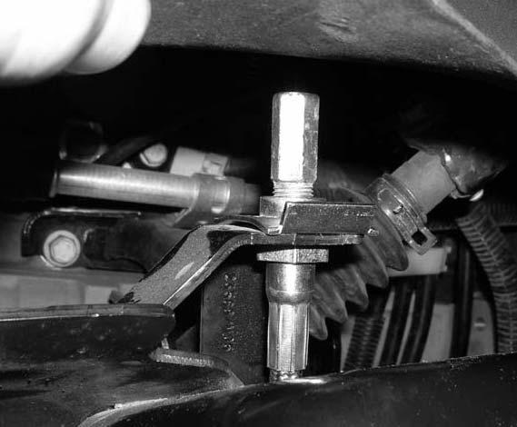
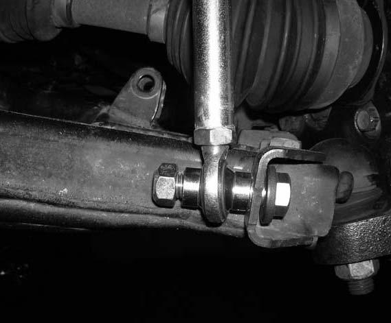
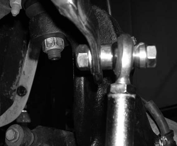
4 Please follow instructions carefully: Before installation begins, measure from the center of the hub, to the bottom of the fender well, and record measurements below. Pre-installation measurements: Driver side front: Passenger side front: Driver side rear: Passenger side rear: At the end of the installation take the same measurements and compare to the pre-installation measurements. Post installation measurements: Driver side front: Passenger side front: Driver side rear: Passenger side rear: Front end installation: 1. To begin installation, block the rear tires of the vehicle so that the vehicle is stable and can t roll backwards. Safely lift the front of the vehicle and support the frame with a pair of jack stands. Place a jack stand on both the driver and the passenger side. Next, remove the front wheels and tires from both sides. 2. Working on the driver side, remove the torsion bar adjusting bolt and block and set aside for later re-installation. Repeat procedure on the passenger side. Photo # 1 3. Working on the driver side, using white out, scribe a mark on the rear portion of the torsion bar and the torsion bar key. Also, at this time, scribe a mark on the front portion of the torsion bar and the torsion bar bracket bolted to the stock lower control arm. Repeat procedure on the passenger side. Special note: It is also a good idea to mark the driver and passenger side torsion bars. Also mark the front of the torsion bar. This will help to make sure that the torsion bars are re-installed back into the stock location. Photo # 2 Photo # 3 4. Working on the driver side, push up on the stock torsion bar and remove the stock torsion bar key. Set the stock torsion bar key aside for later re-installation. Remove the driver side torsion bar from the vehicle and set aside for later re-installation. Repeat procedure on the passenger side. Photo # 4 5. Working on the driver side, carefully remove the (2) stock ABS line mounts that attach the stock ABS line to the stock upper control arm. Next remove the stock ABS line bracket that is attached to the stock knuckle using a 7 mm wrench. The stock hardware may be discard. Repeat procedure on the passenger side. Photo # 5 Photo # 6 6. Working on the driver side, loosen but do not remove the stock nut holding the stock outer tie rod to the stock knuckle. Using a hammer, carefully hit the knuckle to break the taper. Special note: Take special care not to rip or damage the stock outer tie rod dust boot. Once the taper has been broke, remove the stock nut completely and set aside for later re-installation. Remove the outer tie rod from the stock knuckle. Repeat procedure on the passenger side. Photo # 7 Photo # 8 Photo # 9 7. Working on the driver side, remove the stock shock from the stock upper and lower location. Special note: To make removal of the upper nut easier, an allen head wrench maybe needed to hold the shock from spinning. Set the stock lower hardware aside for later re-installation. The stock upper hardware and the stock shock may be discarded. Special note: New longer front shocks are needed after this suspension system has been installed and the front shocks need to be ordered as a separate part #. If you have not already ordered your front shocks, please feel free to contact Tuff Country or your local Tuff Country dealer and order your front shocks. Tuff Country recommends installing a 21 fully extended hydraulic shock in the front. Photo # 10 Photo # Working on the driver side, remove the (2) stock bolts that connect the stock brake caliper to the stock knuckle. Set the stock bolts aside for later re-installation. Carefully tie the stock brake caliper up and out of the way in the fender well. Repeat procedure on the passenger side. Photo # Working on the front of the vehicle, remove the stock skid plate from the stock location. Save the stock skid plate and the stock hardware for later re-installation. Photo # Working on the driver side, remove the stock sway bar end link from the stock lower control arm. The stock hardware may be discarded. Repeat procedure on the passenger side. Photo # Working on the driver side, remove the stock sway bar from the bottom of the stock frame rail. The stock hardware may be discarded. Repeat procedure on the passenger side. Set the stock sway bar aside for further instructions.
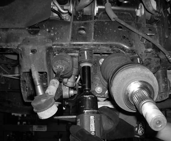
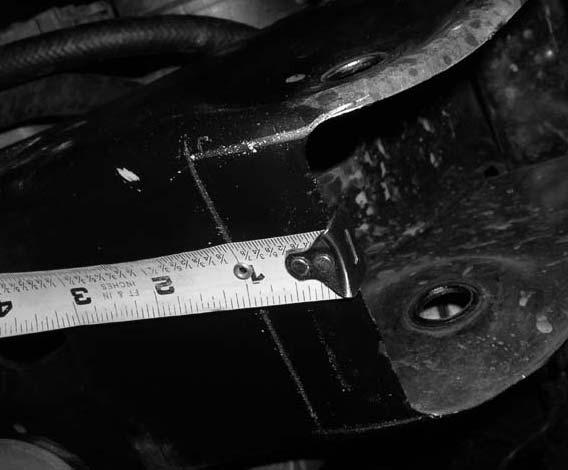
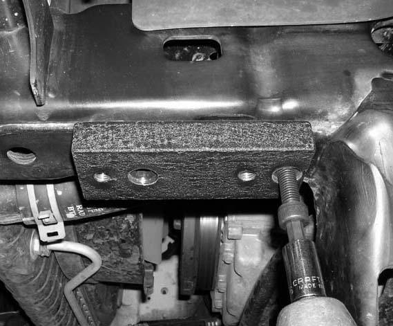
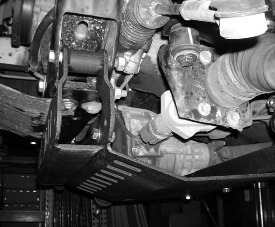
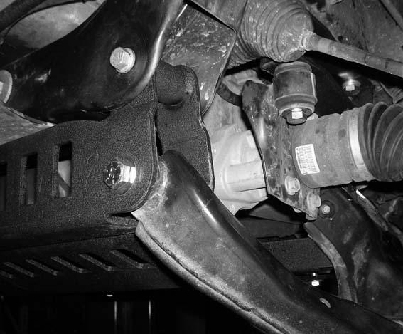
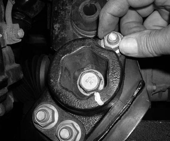
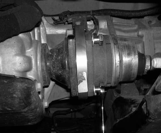
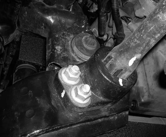
5 Photo # With the stock sway bar out of the vehicle, remove the stock driver and passenger side end links from the stock sway bar and discard the stock end links and hardware. Set the stock sway bar aside for later re-installation. 13. Working on the driver side, remove the stock CV axle nut that connects the stock CV axle to the stock knuckle. Set the stock CV axle nut and washer aside for later re-installation. Photo # Working on the driver side, loosen but do not remove the stock upper ball joint nut that connects that stock upper control arm to the stock knuckle. Repeat procedure on the passenger side. Photo # Working on the driver side, loosened but do not remove the stock lower ball joint nut that connects the stock lower control arm the stock knuckle. Repeat procedure on the passenger side. Photo # Working on the driver side and using a hammer, carefully hit the knuckle to brake the taper on the upper control arm ball joint. Special note: Take special care not to rip or damage the stock upper control arm dust boot. Repeat procedure on the passenger side. Photo # Working on the driver side and using a hammer, carefully hit the knuckle to brake the taper on the lower control arm ball joint. Special note: Take special care not to rip or damage the stock lower control arm dust boot. Repeat procedure on the passenger side. Photo # Working on the driver side, push the stock ABS line bracket out of the stock location in the fender well. Disconnect the stock ABS line from the quick disconnect. Repeat procedure on the passenger side. Photo # 21 Photo # Working on the driver side, move back to the stock nuts holding the upper and lower control arm to the knuckle and remove completely. Set the upper and lower hardware aside for later re-installation. Carefully remove the knuckle from the vehicle and set aside for further instructions. Repeat procedure on the passenger side. Photo # Working on the driver side, remove the stock hardware that connects the stock lower control arm into the stock rear mounting location. Set the stock bolt aside for later re-installation. Remove the stock hardware that connects the stock lower control arm into the stock front mounting location. Set the stock hardware aside for later re-installation. Also set the stock lower control arm aside for later re-installation. Repeat procedure on the passenger side. Photo # 24 Photo # 25 Photo # Place a pair of hydraulic floor jacks under the front differential. Carefully raise up on both hydraulic floor jacks at the same time until they come into contact with the front differential. 22. Working on the driver side, remove the (2) stock bolts that connect the stock differential to the bottom of the stock frame rail. The stock hardware may be discarded. Repeat procedure on the passenger side. Carefully lower down on both hydraulic floor jacks at the same time allowing enough room for the new driver and passenger side differential relocation bracket to be installed. Photo # Locate the new driver and passenger side differential relocation brackets. Locate (4) 14 mm x 50 bolts, (4) 14 mm flat washers and (4) 14 mm lock washers from hardware bag 14045NB. Working on the driver side, install the new differential relocation bracket to the bottom side of the stock frame rail and secure using the new 14 mm x 50 mm bolts and hardware. Do not tighten at this time. Special note: the taller portion of the new differential relocation bracket needs to be installed towards the front of the vehicle. Repeat procedure on the passenger side. Photo # Locate (4) 9/16 x 3 1/2 bolts, (8) 1/2 USS flat washers and (4) 9/16 unitorque nuts from hardware bag 14045NB. Carefully raise up on both hydraulic floor jacks until the stock front differential can be attached to the newly installed differential relocation brackets. Working on the driver side, secure the stock differential to the newly installed differential relocation bracket using the new 9/16 x 3 1/2 bolts and hardware. Do not tighten at this point. Repeat procedure on the passenger side. Photo # Working on the driver side, apply some thread locker or lock tite to the new 14 mm x 50 mm bolts and torque to 85 ft lbs. Apply some thread locker or lock tite to the new 9/16 x 3 1/2 bolt and torque to 85 ft lbs. Repeat procedure on the passenger side. Carefully remove the hydraulic floor jacks from under the vehicle. 26. Working on the driver side front lower control arm pocket, measure 1 from the leading edge towards the inside of the vehicle and scribe a mark from the front of the vehicle to the rear. Repeat procedure on the passenger side. Photo # 30
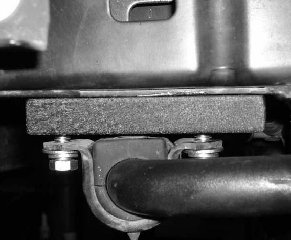
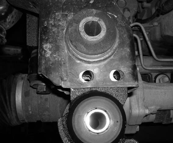
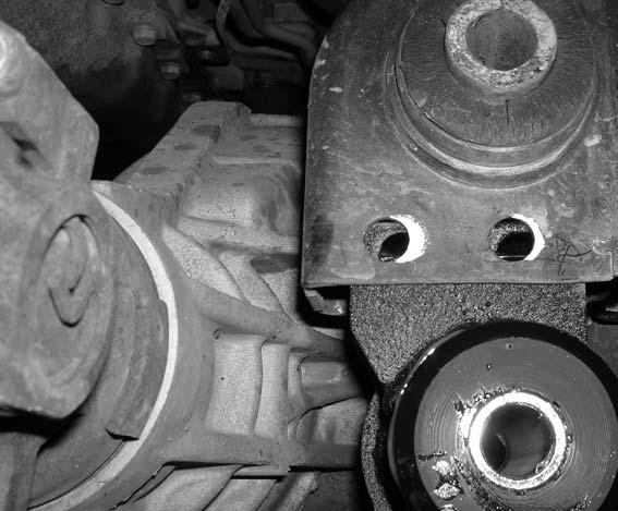
6 27. Working on the driver side, using a die grinder, carefully cut the stock front cross member as indicated in photo # 31 & 32. Repeat procedure on the passenger side. Special note: Tuff Country highly recommends NOT using a torch when making this cut. Photo # 31 Photo # Locate the new driver and passenger side front sway bar relocation bracket. Also, locate (4) 10 mm x 26 mm socket head cap screws from hardware bag 14045NB. Working on the driver side, install the new driver side sway bar relocation bracket to the stock sway bar location on the bottom side of the stock frame rail. Make sure to use thread locker or lock tite and torque to 25 ft lbs. Repeat procedure on the passenger side. Photo # Locate the (4) 3/8 x 3/4 bolts, (4) 5/16 USS flat washers and (4) 3/8 lock washers from hardware bag 14045NB. Also locate the stock front sway bar. Install the driver side of the stock sway bar to the newly installed sway bar relocation bracket and secure using the new 3/8 x 3/4 bolt and hardware. Repeat procedure on the passenger side. Do not tighten fully but tighten enough so that the sway bar can be pushed up and out of the way. These bolts will be torqued once the new sway bar end links have been installed. Photo # Locate the stock skid plate and the stock hardware. Install the stock skid plate into the stock location and secure using the stock hardware. Make sure to install thread locker or lock tite and torque to 18 ft lbs. 31. Locate the new front cross member and the stock front lower control arm hardware. Install the new front cross member into the stock front lower control arm pockets and secure using the stock lower control arm hardware. Do not tighten at this point. Photo # Locate the new rear cross member. Also, locate (2) new grease sert fitting from hardware bag 14045NB. Install the new grease sert fitting into the new rear cross member. Take special care not to damage the new grease sert fitting during installation. Photo # Locate (4) PB2456 poly bushings from hardware bag 14045NB1. Also, locate (2) S10115 sleeves from sleeve bag 14045SL. Install the new bushings and sleeves into the new rear cross member. Special note: Make sure to use a lithium or moly base grease prior to inserting the new bushings and sleeves into the new rear cross member. This will increase the life of the bushing as well as prevent squeaking. Installer note: It is recommended to inform the customer that these bushings need to be lubed regularly. A suggestion is to make sure that these bushings are lubed through the sert fitting every time the customer has their oil changed. Failure to lube the bushings properly could cause the bushing to fail prematurely. Photo # Locate (4) 7/16 x 2 1/2 bolts, (8) 3/8 USS flat washers and (4) 7/16 unitorque nuts from hardware bag 14045NB. Working on the driver side, install the new rear cross member into the rear lower control arm pocket and secure using the new 7/16 x 2 1/2 bolts and hardware. Do not tighten at this point. Repeat procedure on the passenger side. Photo # Due to some inconsistencies, the stock rear lower control arm mounting points may need to be dremelled so that the new rear cross members can be installed. If this is the case on the vehicle that are working on, refer to photo # 39 & 40 and open up the stock holes so that the new rear cross member can be installed. Photo # 39 / driver side Photo # 40 / passenger side 36. Locate the new lower skid plate. Also, locate (6) 1/2 x 1 1/4 bolts, (12) 7/16 USS flat washers and (6) 1/2 unitorque nuts from hardware bag 14045NB. Install the new lower skid plate to the newly installed front and rear cross member and secure using the new 1/2 x 1 1/4 bolts and hardware. Do not tighten at this point. Photo # Move back to the (4) 7/16 x 2 1/2 bolts securing the new rear cross member into the rear lower control pocket and add some thread locker or lock tite and torque to 45 ft lbs. 38. Locate the driver and passenger side stock lower control arms. On the longer leg of the rear portion of the control arms, measuring 3 from the leading edge of the control arms and scribe a mark. Now measure 1/4 from the inside towards the outside of the lower control arms and scribe a mark. On the shorter leg of the control arms, measure 2 from the leading edge of the stock lower control arms and scribe a mark. Now measure 1/4 from the from the inside towards the outside of the lower control arms and scribe a mark. Photo # 42 / longer leg Photo # 43 / shorter leg 39. Using a die grinder carefully cut out the material that was measured in step # 38 on both the driver and passenger side control arms. Special note: Tuff Country highly recommends NOT to use a torch when performing this step. Photo # Working on the driver side lower control arm and referring to photo # 45, remove just one stock torque head
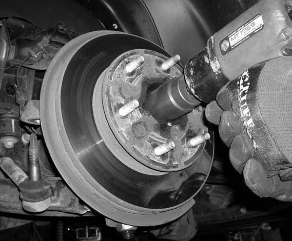
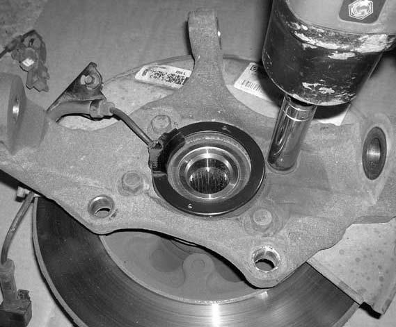
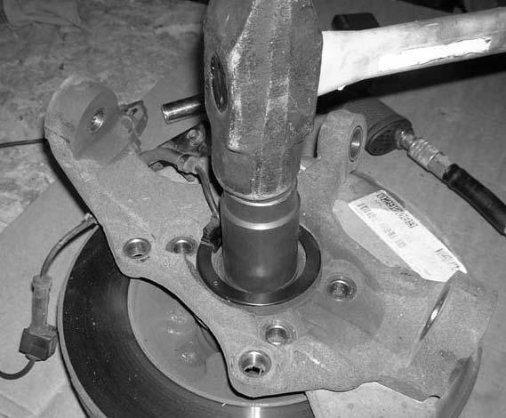
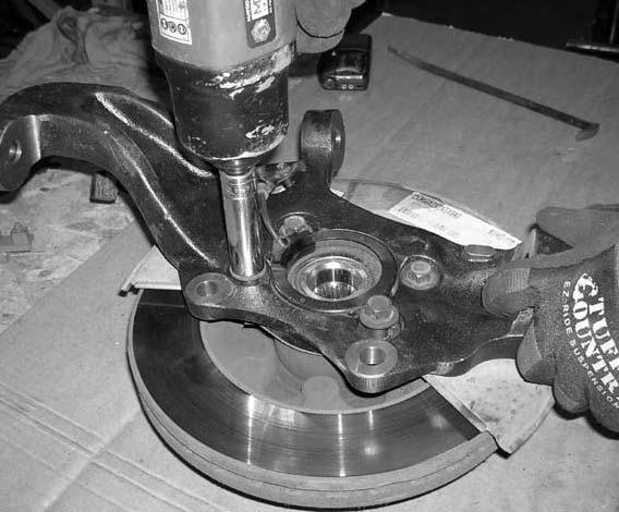
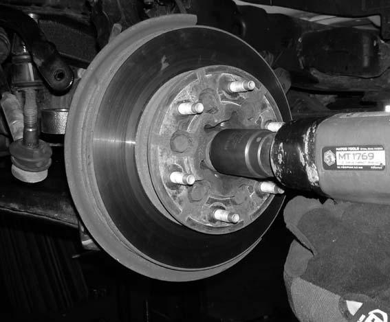
7 mounting hardware that connects the stock torsion bar bracket to the stock lower control arm. Set the stock hardware aside for later re-installation. Repeat procedure on the passenger side lower control arm. Photo # Locate (2) new 5/8 x 4 1/2 bolts, (4) 9/16 USS flat washers and (2) 5/8 unitorque nuts from hardware bag 14045NB. Also, locate the stock rear mounting hardware was was removed in step # 20. Working on the driver side, install the modified stock lower control arm into the newly installed front and rear cross members. Secure the front portion of the lower control arm to the front cross member using the new 5/8 x 4 1/2 bolts and hardware. Do not tighten at this point. Secure the rear portion of the lower control arm to the rear cross member using the stock hardware. Make sure to use thread locker or lock tite and torque to 133 ft lbs. Repeat procedure on the passenger side. Photo # Working on the driver side, remove the stock bump stop from the stock bump stop cup and discard. Repeat procedure on the passenger side. Photo # Locate (2) 3/8 x 1 bolts, (2) 5/16 USS flat washers and (2) 3/8 lock washers from hardware bag 14045NB. Also locate (2) new bump stop relocation brackets. Working on the driver side, install the new bump stop bracket into the stock bump stop cup and secure using the new 3/8 x 1 bolt and hardware. Make sure to use thread locker or lock tite and torque to 22 ft lbs. Special note: the recess on the new bump stop bracket will slide up into the stock bump stop cup. Repeat procedure on the passenger side. Photo # 48 Photo # Locate (2) new PB6052 poly bump stops from hardware bag 14045NB1. Special note: There are (2) different sizes of bump stops in hardware bag 14045NB1, the PB6052 is the taller of the (2) bump stops. Working on the driver side, install the new bump stop to the newly installed bump stop bracket. Make sure to sure thread locker or lock tite and hand tighten. Repeat procedure on the passenger side. Photo # Locate the stock torqued head torsion bar mounting bolt that was removed in step # 40. Working on the driver side, re-install the stock torqued head torsion bar mounting bolt into the stock location and secure using the stock nut. Make sure to use thread locker or lock tite and torque to 45 ft lbs. Repeat procedure on the passenger side. Photo # Locate the driver and passenger side stock knuckles. Remove the (4) stock bolts that connect the stock knuckle to the stock hub assembly. Save the stock hardware for later re-installation. Carefully remove the stock hub assembly from the stock knuckle. Special note: Take special care not to damage the stock hub assembly during removal. Also, notice the placement of the stock ABS sensor ring and wire. The stock knuckle may be discarded. Repeat procedure on the passenger side stock knuckle. Photo # 52 / bolt removal Photo # 53 / hub removal 46. Locate the new driver and passenger side knuckles. Install the stock hub assemblies into the new knuckles and secure using the stock hardware that was removed in step # 45. Make sure to use thread locker or lock tite and torque to 92 ft lbs. Special note: Take special care not to damage the stock hub assembly during installation. Also, make sure that the stock ABS sensor ring and wire is installed back into the stock position. Photo # Working on the new knuckles and the stock hub assemblies, remove the stock ABS retaining mounting bracket from the stock ABS line and discard. Photo # Locate the stock upper and lower control arm mounting hardware that was removed in step # 19. Working on the driver side, install the new driver side knuckle into the stock upper and lower control arm and secure using the stock hardware. Do not tighten at this point. Repeat procedure on the passenger side. 49. Locate (2) new ABS line clips from brake line bag Locate (2) ABS line clips from hardware bag 14045NB1. Also, locate (4) 5 mm x 12 mm hex cap bolts and (4) M5 flat washers from hardware bag 14045NB. Working on the driver side, install the new ABS line clips and ABS lines to the new knuckles and secure using the new 5 mm x 12 mm hex cap bolts and hardware. Make sure to use thread locker or lock tite. Special note: Using a hammer, carefully hammer the upper ABS line clip closed so that the ABS line will not come out of the bracket. Repeat procedure on the passenger side. Photo # 56 Photo # Working on the driver side, torque the lower control arm ball joint nut to 107 ft lbs. and the upper control arm ball joint nut to 55 ft lbs. Repeat procedure on the passenger side. 51. Locate the stock CV axle nuts and washers that were removed in step # 13. Working on the driver side, secure the stock CV axle to the new knuckle and stock hub assembly using the stock CV axle nut and washer. Make sure to use thread locker or lock tite and torque to 184 ft lbs. Repeat procedure on the passenger side. Photo # 58
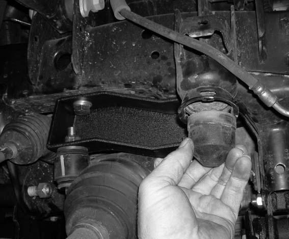
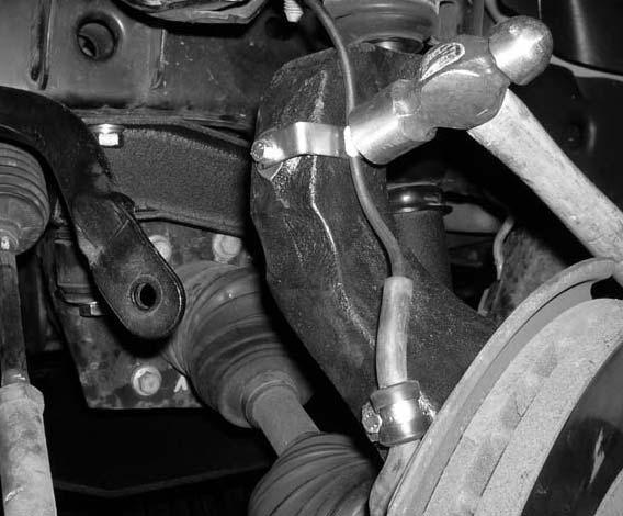
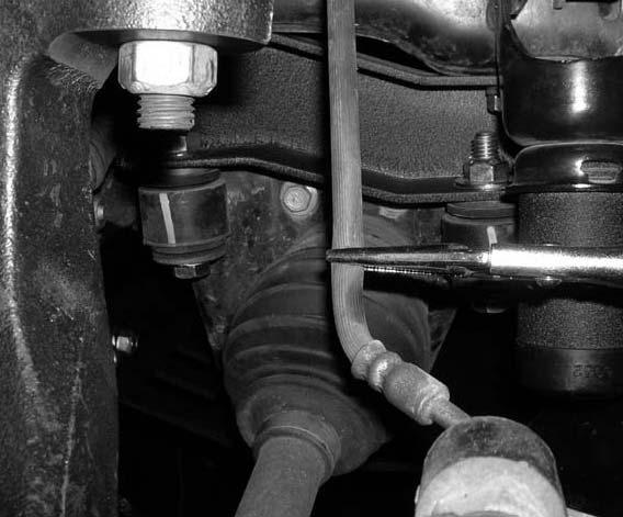
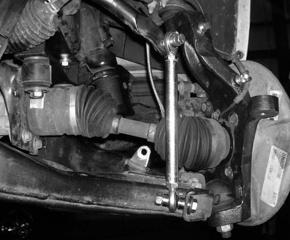
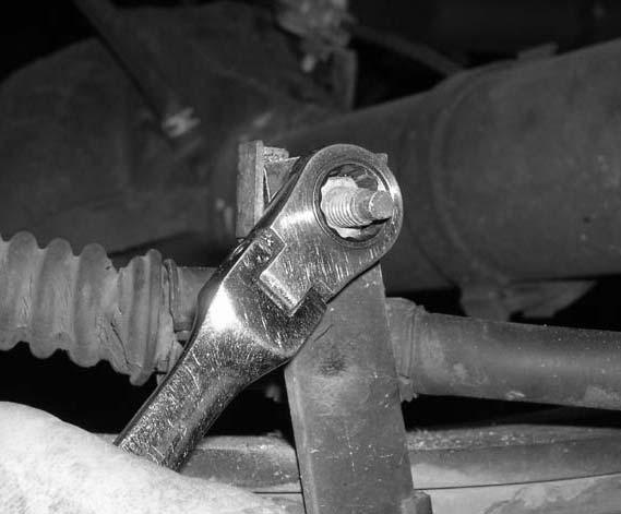
8 52. Locate the stock brake caliper mounting hardware that was removed in step # 8. Working on the driver side, secure the stock brake caliper to the new knuckle and secure using the stock hardware. Make sure to use thread locker or lock tite and torque to 129 ft lbs. Repeat procedure on the passenger side. 53. Working on the driver side, attach the stock ABS line back to the stock location on the stock upper control arm. Now re-connect the stock ABS line back to the quick release clip and secure the stock ABS line bracket to the back side of the stock fender well. Repeat procedure on the passenger side. 54. Working on the driver side and using a pair of vise grips, clamp off the stock brake line. Repeat procedure on the passenger side. Photo # Working on the driver side, remove the stock brake line from the stock upper mounting location and at the stock brake caliper. Save the stock lower mounting hardware. Repeat procedure on the passenger side. Special note: Once the stock brake line has been removed, brake fluid is going to leak out. If is a good idea to have something to catch the fluid so it does not leak out all over the floor. 56. Locate the new brake lines from bag Working on the driver side, install the new brake line into the upper location and use the new brake line clip to hold it into the upper location. Next, secure the lower portion of the brake line to the stock brake caliper using the stock hardware. Repeat on passenger side. Photo # 60 / upper location Photo # 61 / lower location 57. Working on the driver side, carefully drill out the stock sway bar bracket that is attached to the stock lower control arm to 1/2. Repeat procedure on the passenger side. Photo # Working on the driver side, carefully dremel out the stock sway bar so that it will accept a 7/16 bolt. Repeat procedure on the passenger side. Photo # Locate (4) S10116 heim joints from hardware bag NB1. Also locate (2) S10117 sway bar end links from hardware bag 14045SL. Install the new heim joints into each end of the new sway bar end links. Tighten the heim joints all the way down until their is no more threads. 60. Locate (2) new 1/2 x 2 1/4 bolts and (2) 1/2 unitorque nuts from hardware bag 14045NB. Locate (4) S10118 spacer sleeves from hardware bag 14045SL. Also, locate (2) SUW-12 from hardware bag 14045NB1. Working on the driver side, attach the new sway bar end link heim joint to the stock sway bar bracket that is attached to the stock lower control arm. Do not tighten at this point. Please refer to photo # 64 for proper installation. Repeat procedure on the passenger side. Photo # Locate (2) new 7/16 x 2 bolts, (2) 3/8 USS flat washer and (2) 7/16 unitorque nuts from hardware bag 14045NB. Also, locate (2) S10123 spacer sleeves and (2) S10124 taper spacer sleeve from hardware bag 14045SL. Working on the driver side, secure the top heim joint on the new sway bar end link to the stock sway bar using the new 7/16 x 2 bolts, hardware and spacer sleeves. Do not tighten at this point. Please refer to photo # 65 for proper installation. Repeat procedure on the passenger side. Photo # Working on the driver side, torque the lower 1/2 sway bar bolt to 65 ft lbs. and the upper 7/16 sway bar bolt to 45 ft lbs. Repeat procedure on the passenger side. Photo # Working on the driver side, place a hydraulic floor under the driver side lower control arm. Carefully raise up on the lower control arm until the upper control arm clears the stock upper bump stop. Locate (2) new PB6199 poly bump stops from hardware bag 14045NB1. Special note: There are (2) different sizes of bump stops in hardware bag 14045NB1, the PB6199 is the shorter of the (2) bump stops. Also, locate (2) 3/8 nylock nuts and (2) 5/16 USS flat washers from hardware bag 14045NB. Working on the driver side, install the new bump stop to the stock upper bump stop bracket (hole is already provided) and secure using the new hardware. Torque to 28 ft lbs. Repeat procedure on the passenger side. Photo # Locate the stock outer tie rod end hardware that was removed in step # 6. Working on the driver side, rotate the stock outer tie rod 180 degrees from the stock location and install the stock outer tie rod into the new knuckle and secure using the stock hardware. Make sure to use thread locker or lock tite and torque to 45 ft lbs. Repeat procedure on the passenger side. Photo # Remove the stock front drive shaft from the transfer case mounting mount. The stock hardware may be discarded. Photo # Locate the new drive shaft spacer. Also, locate (4) new 10 mm x 40 mm bolts and (4) 10 mm lock washers from hardware bag 14045NB. Install the new driver shaft spacer between the stock drive shaft and the stock transfer case and secure using the new 10 mm x 40 mm bolts and hardware. Make sure to use thread locker or lock tite and torque to 35 ft lbs. Photo # 70
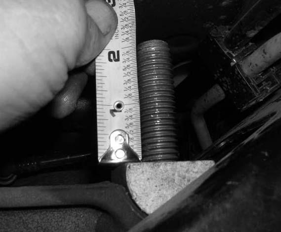
9 67. Working on the driver side, install a fair amount of grease into the stock torsion bar bracket attached to the stock lower control arm. Repeat procedure on the passenger side. Photo # Locate the stock driver side torsion bar. Install the driver side torsion bar into the stock torsion bar bracket attached to the stock lower control arm. Special note: Make sure that our marks that were scribed earlier line up with each other. This will ensure that the stock torsion bar is installed into the stock location. Also, it is important that the stock driver side torsion bar is installed on the driver side and the stock passenger side torsion bar is installed on the passenger side. If this does not happen, problems may occur. Photo # Move back to the new hardware securing the new skid plate to the front and rear cross member and add some thread locker or lock tite. Working on the front portion of the skid plate that attaches to the front cross member first, torque the new hardware to 65 ft lbs. and then torque the rear hardware to 65 ft lbs. 70. Working on the driver side, move back to the stock mounting hardware holding the new front cross member into the stock location and add some thread locker or lock tite and torque to 122 ft lbs. Repeat procedure on the passenger side. 71. Working on the driver side, move back to the new 5/8 x 4 1/2 bolt holding the stock lower control arm to the new front cross member and add some thread locker or lock tite and torque to 115 ft lbs. Repeat procedure on the passenger side. Photo # Locate the stock driver and passenger side torsion bar keys that were removed in step # 4. Working on the driver side, install the stock torsion bar key to the stock torsion bar. Special note: Make sure that our marks that were scribed earlier line up with each other. This will ensure that the stock torsion bar is installed into the stock location. Also, it is important that the stock driver side torsion bar is installed on the driver side and the stock passenger side torsion bar is installed on the passenger side. If this does not happen, problems may occur. Repeat procedure on the passenger side. 73. Locate the stock torsion bar adjusting blocks and bolts that were removed in step # 2. Working on the driver side, install the stock torsion bar block and bolt into the stock location and tighten adjusting bolt until there is 2 3/16 of thread sticking out of the torsion bar adjusting block. Repeat procedure on the passenger side. Photo # Locate the new front shocks. Special note: New longer front shocks are needed, if you have not already ordered shocks, please contact Tuff Country or your local Tuff Country dealer and order the proper shocks. Tuff Country recommends using a 21 fully extended hydraulic shock. Locate (4) PB8297 upper shock bushings from hardware bag 14045NB1. Also, locate (4) S10107 upper shock washers from hardware bag 14045NB. Install the new shock boot onto the new shocks. Special note: Tuff Country EZ-Ride Suspension highly recommends that the shocks are installed with shock boots. If shock boots are not installed, damaged my occur to the piston of the new shock. Working on the driver side, install the new shock into the stock lower mounting location using the stock hardware that was removed in step # 7. Make sure to use thread locker or lock tite and torque to 65 ft lbs. Install the new shock into the stock upper location using the new upper shock bushings, over size washers and the new nut that was packaged with the new shocks. Torque to 18 ft lbs. Repeat procedure on the passenger side. 75. Check and double check to make sure that all steps for the front end were performed properly and then check again. 76. Install the tires and wheels and carefully lower the vehicle to the ground. 77. To begin installation, block the front tires of the vehicle so that the vehicle is stable and can t roll forward. Safely lift the rear of the vehicle and support the frame with a pair of jack stands. Place a jack stand on both the driver and passenger side. Next, remove the wheels and tires from both sides. Repeat procedure on the passenger side. 78. Working on the driver side, remove the stock shock from the stock upper and lower mounting points and save the stock hardware for later re-installation. The stock shocks may be discarded. Special note: New longer rear shocks are needed, if you have not already ordered shocks, please contact Tuff Country or your local Tuff Country dealer and order the proper shocks. Tuff Country recommends using a 26 fully extended hydraulic shock. Repeat procedure on the passenger side. 79. Place a pair of hydraulic floor jacks under the rear differential and carefully raise up on both hydraulic floor jacks at the same time until they come into contact with the rear differential. 80. Working on the driver side, remove the stock emergency brake cable from the stock bracket attached to the stock rear spring. Save the stock hardware and let the stock emergency brake cable hang. Photo # Working on the driver side, remove the stock u-bolts from the stock location and save the stock u-bolts and
10 hardware for later re-installation. Set the stock lower u-bolt plate aside for later re-installation. Repeat procedure on passenger side. 82. Carefully raise up on both hydraulic floor jacks until the stock spring assemblies separate from the stock rear axle. 83. Locate (2) new rear add-a-leaf. Also, locate (2) 5/16 x 6 centering bolts and (2) 5/16 fine nuts from hardware bag 14045NB1. Install the new rear add-a-leaf into the stock spring assembly. Secure the new rear add-a-leaf to the stock spring assembly using the new 5/16 center bolt and nut. Torque to 22 ft. lbs. Special note: If the new add-aleaf that you are installing into the stock spring assembly has an offset center hole location, place the longest side of the add-a-leaf towards the rear of the vehicle. Also the new add-a-leaf should be installed into the stock spring assembly in progression in order, from longest to shortest. Also, Tuff Country EZ-Ride Suspension recommends not using any air tools when installing the new add-a-leafs into the stock spring assembly. If air tools are used the centering bolt may strip, causing the stock spring assembly to come apart. With a suitable cutting tool, cut off the extra thread from the new centering bolt. Repeat procedure on passenger side. 84. Carefully lower down on both hydraulic floor jacks at the same time until the stock rear axle seats properly with the newly modified stock rear springs. 85. Locate the stock lower u-bolt plates, the stock u-bolts and the stock u-bolt hardware that were removed in step # 81. Working on the driver side, install the stock u-bolts into the stock location and secure using the stock hardware. Repeat procedure on the passenger side. Torque the stock u-bolts to 70 ft lbs. 86. Locate the new rear shocks. Special note: New longer rear shocks are needed, if you have not already ordered shocks, please contact Tuff Country or your local Tuff Country dealer and order the proper shocks. Tuff Country recommends using a 26 fully extended hydraulic shock. Also, locate (2) P98 shock clevis mounts from hardware bag 14045NB1. Working on the new shocks, install the new shock bushing into the upper and lower eyelets of the new shocks. Next, install the new proper shock sleeves into the previously installed lower shock bushings. Install the new shock boots onto the new shocks. Special note: Tuff Country EZ-Ride Suspension highly recommends that the shocks are installed with shock boots. If shock boots are not installed, damage may occur to the piston of the new shock. Next, install the new P98 shock clevis mounts into the upper eyelet s of each shock. Special note: Make sure to use a lithium or moly base grease prior to inserting the new shock bushings, sleeves and clevis mounts into the new shock eyelets. This will increase the life of the bushing as well as prevent squeaking. Working on the driver side, install the new shock into the stock upper and lower location and secure using the stock hardware that was removed in step # 78. Special note: Make sure to use thread locker or lock tite and torque the upper mounting hardware to 28 ft lbs and the lower stock mounting hardware to 75 ft lbs. Repeat procedure on the passenger side. 87. Locate the stock emergency brake cable mounting hardware that was removed in step # 80. Working on the driver side, install the stock emergency brake cable to the stock bracket and secure using the stock hardware. Make sure to use thread locker or lock tite and torque to 18 ft lbs. 88. Remove both hydraulic floor jacks from under the vehicle. 89. Install the tires and wheels and carefully lower the vehicle to the ground. 90. Check and double check to make sure that all steps were performed properly for the rear end and check again. Congratulations, installation complete! Special note: After the completion of the installation, Tuff Country EZ-Ride Suspension recommends taking the vehicle to an alignment shop and having a proper front end alignment performed. Tuff Country EZ-Ride Suspension recommends that a complete re-torque is done on all bolts associated with this suspension system. It is the customers responsibility to make sure that a re-torque is performed on all hardware associated with this suspension system after the first 100 miles of installation. It is also the customers responsibility to do a complete re-torque after every 3000 miles or after every off road use. Neglect of following these steps could cause brackets to come loose and cause serious damage to the suspension system and to the vehicle. Tuff Country EZ-Ride Suspension packages (2) sets of instruction sheets with this box kit. (1) is for the installer and (1) is for the customer. The (1) for the customer has some post installation procedure literature and it is the installers responsibility to make sure that the customer receives a copy of the installation manual along with the literature. If you have any questions or concerns, please feel free to contact Tuff Country or your local Tuff Country dealer.


11 Photo # 1 Photo # 2 Photo # 3 Photo # 4 Photo # 5 Photo # 6


12 Photo # 7 Photo # 8 Photo # 9 Photo # 10 Photo # 11 Photo # 12


13 Photo # 13 Photo # 14 Photo # 15 Photo # 16 Photo # 17 Photo # 18


14 Photo # 19 Photo # 20 Photo # 21 Photo # 22 Photo # 23 Photo # 24


15 Photo # 25 Photo # 26 Photo # 27 Photo # 28 Photo # 29 Photo # 30


16 Photo # 31 Photo # 32 Photo # 33 Photo # 34 Photo # 35 Photo # 36


17 Photo # 37 Photo # 38 Photo # 39 Photo # 40 Photo # 41 Photo # 42


18 Photo # 43 Photo # 44 Photo # 45 Photo # 46 Photo # 47 Photo # 48


19 Photo # 49 Photo # 50 Photo # 51 Photo # 52 Photo # 53 Photo # 54


20 Photo # 55 Photo # 56 Photo # 57 Photo # 58 Photo # 59 Photo # 60


21 Photo # 61 Photo # 62 Photo # 63 Photo # 64 Photo # 65 Photo # 66


22 Photo # 67 Photo # 68 Photo # 69 Photo # 70 Photo # 71 Photo # 72

23 Photo # 73 Photo # 74 Photo # 75

")
 Rear")
24 (1) Driver side knuckle (1) Passenger side knuckle (1) Front cross member (1) Rear cross member

 DS")

 PS bracket")


")
 Heim")
 Rear")
")
25 (1) Front lower skid plate (1) DS differential relocation bracket (1) PS differential relocation bracket (2) ABS brackets (2) Sway bar brackets (2) Bump stop brackets (1) Front drive shaft spacer S10118 (4) Spacer sleeves S10116 (4) Heim joints TCI-R26 (2) Rear add-a-leafs S10123 (2) Spacer sleeve S10124 (2) Milled sleeves
Installation manual. 3.5 suspension system Chevy / GMC 2500HD / 3500HD With contact overloads Part # 13090
 Part # 13090 2011-2016 Chevy / GMC 2500HD / 3500HD With contact overloads 3.5 suspension system Part # Description Qty. 13085-01 DS & PS Upper control arm 2 13085-02 DS & PS Front upper shock bracket 2
Installation manual. 3 suspension system Toyota Tacoma. Part # Part # Important customer information: Toyota Tacoma
 Installation manual 3 suspension system 2005 2008 Toyota Tacoma Part # 52907 sj111607rev.02 Part # 52907 2005-2008 Toyota Tacoma 3 suspension system Part # Description Qty. 52907-01 Pre-load spacer 2 52907-02
Installation manual Hummer H3 4 suspension system Part # Part # Important customer information Hummer H3 4 Suspension system
 Installation manual Hummer H3 4 suspension system 2006 Part # 14040 sj022807rev.03 Part # 14040 2006 Hummer H3 4 Suspension system Parts list: Part # Description Qty. 14040-01 DS knuckle 1 14040-02 PS
Installation manual. 4.5 suspension system June 2007 Dodge Ram 2500 / Part # Part # Important customer information:
 Installation manual 4.5 suspension system 2003 - June 2007 Dodge Ram 2500 / 3500 Part # 34003 sj11407rev.03 Part # 34003 2003 - June 2007 Dodge Ram 2500 / 3500 4.5 suspension system Part # Description
Installation manual 3 front / 2 rear suspension system FJ / Runner Part # sj110607rev.03
 Part #: 52000 2007-2014 Toyota FJ / 2003-2009 4Runner 3 front / 2 rear suspension system Parts list: Part # Description Qty. 52907-01 Pre load spacer 2 52907-02 Strut spacer 2 MO3531BK-01 Rear coil spring
Installation manual. Toyota Tundra 4WD & 2WD. 2.5 Suspension kit. Part # Part # Important customer information:
 Installation manual 2007-2016 Toyota Tundra 4WD & 2WD 2.5 Suspension kit Part # 53070 sj11082011rev.03 Part # 53070 2007-2016 Toyota Tundra 4WD & 2WD 2.5 Suspension kit Part # Description Qty. 53070-01
Installation manual. 3 suspension system Toyota Tacoma. 4x4 and 2WD PreRunner. Part # Part # Important customer information:
 Installation manual 3 suspension system 2005 2018 Toyota Tacoma 4x4 and 2WD PreRunner Part # 52907 sj11112011rev.05 Part # 52907 2005-2018 Toyota Tacoma 4x4 and 2WD PreRunner 3 suspension system Part #
Installation manual 2 Leveling kit GM x 4. Part # Part # Important customer information: GM x 4
 Installation manual 2 Leveling kit 2007-2008 GM 1500 4 x 4 Part # 12000 sj121007rev.02 Part # 12000 2007-2008 GM 1500 4 x 4 2 leveling system Parts list: Part # Description Qty. 12000-01 Front leveling
Installation manual 3 SUSPENSION SYSTEM Dodge Ram 2500/3500 OLD PART # D32B NEW PART # 33920
 Installation manual 3 SUSPENSION SYSTEM 1994 2002 Dodge Ram 2500/3500 OLD PART # D32B NEW PART # 33920 sj060506rev.02 Old part # D32B New part # 33920 Dodge Ram 2500/3500 3 suspension system Parts list:
Installation manual. Long arm upgrade kit of lift March 1999 Dodge Ram 1500, 2500 and Part # 30945
 Installation manual Long arm upgrade kit 2-4.5 of lift 1994 - March 1999 Dodge Ram 1500, 2500 and 3500 Part # 30945 sj02222012rev.01 Part # 30945 1994 - March of 1999 Dodge Ram 1500,2500 & 3500 Long arm
Installation manual. 2 Suspension System. Ford F150 4WD and 2WD. Part # Part # Ford F150 4WD and 2WD
 Installation manual 2 Suspension System 2009-2018 Ford F150 4WD and 2WD Part # 22929 sj12112013rev.03 Part # 22929 2009-2018 Ford F150 4WD and 2WD 2 Suspension System Part # Description Qty. 22909-01 Front
Installation manual. 3 Suspension Kit Ram WD. Part # Part # Important customer information: 2013 Ram WD
 Installation manual 3 Suspension Kit 2013-2016 Ram 3500 4WD Part # 33118 sj10232013rev.01 Part # 33118 2013 Ram 3500 4WD 3 Suspension Kit Part # Description Qty. 33118-01 Front coil spring spacer 2 33118-02
Installation manual Toyota Tundra 4WD & 2WD - 2 front leveling kit Toyota Sequoia 4WD & 2WD - 2 front leveling kit Part # 52070
 Part # 52070 2007-2016 Toyota Tundra 4WD & 2WD 2008-2011 Toyota Sequoia 4WD & 2WD 2 front leveling kit Part # Description Qty. 52070-01 Front strut spacers 2 52070NB Hardware bag 1 52070INST Instruction
Installation manual. Rear ladder bars. Chevy/GMC 2500/3500 HD. Part # Part # Important customer information:
 Installation manual 2011-2018 Chevy/GMC 2500/3500 HD Part # 10892 sj07272011rev.01 Part # 10892 2011-2018 Chevy/GMC 2500/3500 HD Part # Description Qty. 10892-01 Rear ladder bar brackets 2 10892-02 Front
Installation manual. 4 suspension system Chevy or GMC WD. Part # Part # Important customer information:
 Installation manual 4 suspension system 2014-2018 Chevy or GMC 1500 4WD Part # 14059 sj09052013rev.01 Part # 14059 2014-2018 Chevy or GMC 1500 4WD 4 suspension system Part # Description Qty. 14056-01 Upper
Installation manual. 2 front / 1 rear spacer kit Jeep Wrangler JK 2 & 4 door Part # 42005
 Part # 42005 2007-2015 Jeep Wrangler JK 2 & 4 door 2 front / 1 rear spacer kit Parts list: Part # Description Qty. 42005-01 Front coil spring spacers 2 42005-02 Rear coil spring spacers 2 42005INST Instruction
INSTALLATION MANUAL 4.5 I.F.S. SUSPENSION CURR. FORD F150 W/4.2 OR 4.6 LITER PART # 24940
 INSTALLATION MANUAL 4.5 I.F.S. SUSPENSION 1997- CURR. FORD F150 W/4.2 OR 4.6 LITER PART # 24940 SJ101402 PART NUMBER : 24940 1997 CURR. FORD F150 W/4.2 OR 4.6 LITER 4.5 SUSPENSION SYSTEM WITH FRONT SPINDLES
Installation manual. Rear traction bars. Ram Ram Part # Part # Important customer information:
 Installation manual Rear traction bars Ram 2500 2003-2013 Ram 3500 2003-2012 Part # 30991 sj12062011rev.01 Part # 30991 2003-2013 Ram 2500, 2003-2012 Ram 3500 Rear traction bars Part # Description Qty.
INSTALLATION MANUAL TOYOTA TUNDRA 5 SUSPENSION SYSTEM PART # 55905
 PART NUMBER : 55905 1999 2003 TOYOTA TUNDRA 5 SUSPENSION SYSTEM PARTS LIST: Part # Description Qty. 55900-01 Driver Side Spindle 1 55900-02 Passenger Side Spindle 1 55905-03 Rear brake proportioning valve
Installation manual. 1.5 front leveling kit. Nissan Titan. Part # Part # Important customer information: Nissan Titan
 Installation manual 1.5 front leveling kit 2004-2015 Nissan Titan Part # 52008 sj071408rev.01 Part # 52008 2004-2015 Nissan Titan 1.5 front leveling kit Part # Description Qty. 52008-01 Front strut spacers
Installation manual 3 suspension system Toyota Tacoma 4 x 4 & PreRunner Part # sj rev.03
 Part #: 52904 1995-2004 Toyota Tacoma 4 x 4 & PreRunner 3 suspension system Parts list: Part # Description Qty. 52904-01 Rear brake proportioning valve bracket 1 52907-02 Front pre load spacer 2 52904-03
INSTALLATION MANUAL TOYOTA TACOMA 5 SUSPENSION SYSTEM PART # 54900
 PART NUMBER : 54900 1996 2004 TOYOTA TACOMA 5 SUSPENSION SYSTEM PARTS LIST: Part # Description Qty. 55900-01 Driver Side Spindle 1 55900-02 Passenger Side Spindle 1 54900-01 Rear brake proportioning valve
INSTALLATION MANUAL 4 I.F.S. SUSPENSION CURR. CHEVY SUBURBAN / YUKON XL (WITH 5 LINK REAR END) PART # 14965
 PART # 14965") PART NUMBER : 14965 2000 CURR. SUBURBAN W/ REAR COIL SPRINGS 4 SUSPENSION SYSTEM WITH FRONT SPINDLES PARTS LIST: Part # Description Qty. C4I1SN-07 Passenger Side Differential Drop 1 C4I1SN-23 Driver Side
PART NUMBER : 14965 2000 CURR. SUBURBAN W/ REAR COIL SPRINGS 4 SUSPENSION SYSTEM WITH FRONT SPINDLES PARTS LIST: Part # Description Qty. C4I1SN-07 Passenger Side Differential Drop 1 C4I1SN-23 Driver Side
Installation manual. Front leveling kit. Part # Part # Important customer information: Ram WD Ram WD
 Installation manual Front leveling kit 2014-2018 Ram 2500 4WD 2013-2018 Ram 3500 4WD Part # 32909 sj10182013rev.02 Part # 32909 2014-2018 Ram 2500 4WD 2013-2018 Ram 3500 4WD Front leveling kit Part # Description
Installation manual Strong 6 suspension system Chevy or GMC 1500 Part # 16959
 Part # 16959 1999-2005 Chevy or GMC 1500 Strong 6 suspension system Parts contained in Box 1 of 3 Part # Description Qty. 16955-16 Front cross member 1 16955-17 Rear cross member 1 16955-18 6 integrating
Installation manual. Strong 6 suspension system Chevy or GMC 2500HD. Part # Part # Chevy or GMC 2500HD
 Installation manual Strong 6 suspension system 2001 -- 2010 Chevy or GMC 2500HD Part # 16993 sj030707rev.01 Part # 16993 2001-2010 Chevy or GMC 2500HD Strong 6 suspension system Parts contained in Box
INSTALLATION MANUAL 6 I.F.S. SUSPENSION CURR. CHEVY HEAVY DUTY WD PART # / WITH OUT SHOCKS PART # / WITH SHOCKS
 INSTALLATION MANUAL 6 I.F.S. SUSPENSION 2001 - CURR. CHEVY HEAVY DUTY 2500 2WD PART # 16987 / WITH OUT SHOCKS PART # 16988 / WITH SHOCKS SJ031502 Tuff Country EZ-Ride Suspension highly recommends that
Installation manual 4.5 Suspension system Dodge Ram 1500
 Installation manual 4.5 Suspension system 1994 2001 Dodge Ram 1500 Part # 35910 / 35912K / 35913K jd021816rev.04 Part # 35910 / 35912K / 35913K Dodge Ram 1500 4.5 Suspension system Parts list: Part # Description
Installation manual. 2.5 suspension system. (Except Mega-Cab) Part # Part # Important customer information:
 Part # Part # Important customer information:") Installation manual 2.5 suspension system 2009-2018 Dodge Ram 1500 4WD (Except Mega-Cab) Part # 32102 sj02272013rev.01 Part # 32102 2009-2018 Dodge Ram 1500 4WD (Except Mega-Cab) 2.5 Suspension System
Installation manual 2.5 suspension system 2009-2018 Dodge Ram 1500 4WD (Except Mega-Cab) Part # 32102 sj02272013rev.01 Part # 32102 2009-2018 Dodge Ram 1500 4WD (Except Mega-Cab) 2.5 Suspension System
Installation manual 4.5 Suspension system Dodge Ram 2500 / Old part # D52B New part # Old part # D52B New part # 35920
 Installation manual 4.5 Suspension system 1994 2002 Dodge Ram 2500 / 3500 Old part # D52B New part # 35920 Sj052206rev.03 Old part # D52B New part # 35920 Dodge Ram 2500 / 3500 4.5 Suspension system Parts
Installation Manual. 3 suspension system Ford F150. Part # Part # Important customer information: Ford F150
 Installation Manual 3 suspension system 2015-2018 Ford F150 Part # 23030 SS08282015 Part # 23030 2015-2018 Ford F150 3 suspension system Part # Description Qty. 23000-01 Driver side upper control arm 1
Installation manual. Strong 4 suspension system Chevy or GMC 1500 Part # 14959
 Part # 14959 1999-2005 Chevy or GMC 1500 Strong 4 suspension system Parts contained in Box 1 of 3 Part # Description Qty. 14955-39 Front cross member 1 14955-40 Rear cross member 1 14955-41 4 integrating
INSTALLATION MANUAL 6 SUSPENSION SYSTEM PART # CHEVY/GMC BLZR/SUBURBAN 1/2 TON
 INSTALLATION MANUAL 6 SUSPENSION SYSTEM CHEVY/GMC BLZR/SUBURBAN 1/2 TON 1988 1991 PART # 16730 SJ051402 PART NUMBER : 16730 1988 1991 CHEVY/GMC BLAZER & SUBURBAN 1/2 TON 6 SUSPENSION SYSTEM WITH REAR BLOCKS
Installation manual. 4 performance suspension system Ford F150 or Bronco New part # Old part # F4XRB
 Part # 24814 1981-1996 Ford F150 or Bronco 4 performance suspension system Part # Description Qty. F2XRB-01 DS extended radius arm 1 F2XRB-02 PS extended radius arm 1 F2XRB-03 DS extended radius arm relocation
Installation manual. 2 front leveling kit. (Except Mega-Cab) Part # Part # Important customer information:
 Part # Part # Important customer information:") Installation manual 2 front leveling kit 2014-2018 Dodge Ram 1500 4WD (Except Mega-Cab) Part # 32103 sj02252014rev.01 Part # 32103 2014-2018 Dodge Ram 1500 4WD (Except Mega-Cab) 2 front leveling kit Part
Installation manual 2 front leveling kit 2014-2018 Dodge Ram 1500 4WD (Except Mega-Cab) Part # 32103 sj02252014rev.01 Part # 32103 2014-2018 Dodge Ram 1500 4WD (Except Mega-Cab) 2 front leveling kit Part
Installation manual. 4 suspension system Ford F150 or Bronco. Part # Part # Important customer information:
 Installation manual 4 suspension system 1981-1996 Ford F150 or Bronco Part # 24810 sj121609rev.01 Part # 24810 1981-1996 Ford F150 or Bronco 4 suspension system Part # Description Qty. F401 Front axle
Installation Manual Chevy 2500/3500HD 4x4 3.5 Lift w/ Uniball upper control arms. Part # SS
 Part # 13086 2011-2017 Chevy 2500/3500 HD 4x4 3.5 lift with Uniball upper control arms Part # Description Qty. 13086-01 DS & PS Upper control arm 2 13085-02 DS & PS upper shock bracket 2 13085-03 Limiting
Installation manual 6 suspension system Chevy or GMC 1500 Part # 16955
 Part # 16955 1999-2005 Chevy or GMC 1500 6 suspension system Parts contained in Box 1 of 3 Part # Description Qty. 16955-03 Sub frame 1 16955-10 Front lateral compression arms 2 81350 Rear add-a-leaf /
Installation manual. 4 Suspension system Ford Super Duty F250 / F350. Part # Part # 24975
 Installation manual 4 Suspension system 2005-2016 Ford Super Duty F250 / F350 Part # 24975 SS05272014 Part # 24975 2005-2016 Ford Super Duty F250 / F350 4 Suspension system Part # Description Qty. 24975-CL01
Installation manual. 5 Suspension system Toyota Tundra Part # Part # Toyota Tundra 5 Suspension system
 Part # 55907 2005-2006 Toyota Tundra 5 Suspension system Parts contained in Box 1 of 2 Part # Description Qty. 55905-04 Front upper strut spacer 2 TOYBRAKE-01 Rear brake proportioning valve bracket 1 TOYDSDIFF-01
Installation Manual. Upper Control Arms W/Uniball joint Toyota Tacoma 4wd & 2wd PreRunner. Part # Part # 50930
 Installation Manual Upper Control Arms W/Uniball joint 2005-2016 Toyota Tacoma 4wd & 2wd PreRunner Part # 50930 SS08182014 Part # 50930 Upper Control Arms W/Uniball joint 2005-2016 Toyota Tacoma 4wd &
Installation manual. 4 suspension system Suburban & Tahoe 4WD Avalanche 4WD Part # 14058
 Part # 14058 2007-2013 1500 Suburban & Tahoe 4WD 2007-2012 1500 Avalanche 4WD 4 suspension system Part # Description Qty. 14056-01 Upper strut spacer 2 14056-02 Rear upper shock bracket 2 14056-03 Skid
Installation Manual Ram x4 4 Lift w/upper control arms. Part # Part # 34105
 Installation Manual 2009 2018 Ram 1500 4x4 4 Lift w/upper control arms Part # 34105 ss09172014 Part # 34105 2009-2018 Ram 1500 4x4 4 suspension system w/upper control arms Part # Description Qty. 34105-01
Torque Settings INSTALLATION MANUAL 3 I.F.S. SUSPENSION TOYOTA TACOMA PART # 52904
 INSTALLATION MANUAL 3 I.F.S. SUSPENSION 1995-2002 TOYOTA TACOMA PART # 52904 SJ010702 PART NUMBER : 52904 1995-2002 TOYOTA TACOMA 3 SUSPENSION SYSTEM PARTS LIST: Part # Description Qty. TT212-02 Rear Brake
Torque Settings INSTALLATION MANUAL 3 SUSPENSION SYSTEM CHEVY PICKUP 3/4 TON PART # 13720
 INSTALLATION MANUAL 3 SUSPENSION SYSTEM CHEVY PICKUP 3/4 TON 1973 1987 PART # 13720 SJ050702 PART NUMBER : 13720 1973 1987 CHEVY PICK UP 3/4 TON 3 SUSPENSION SYSTEM / WITH REAR BLOCKS PARTS LIST: Part
INSTALLATION MANUAL 4 SUSPENSION SYSTEM CHEVY PICKUP 3/4 TON PART # 14720
 INSTALLATION MANUAL 4 SUSPENSION SYSTEM CHEVY PICKUP 3/4 TON 1973 1987 PART # 14720 SJ051402 PART NUMBER : 14720 1973 1987 CHEVY PICK UP 3/4 TON 4 SUSPENSION SYSTEM / WITH REAR BLOCKS PARTS LIST: Part
INSTALLATION MANUAL 6 I.F.S. SUSPENSION CHEVY OR GMC 1500 SILVERADO PART # 16955
 INSTALLATION MANUAL 6 I.F.S. SUSPENSION 1999-2003 CHEVY OR GMC 1500 SILVERADO PART # 16955 sj031203rev.01 PART NUMBER : 16955 1999 2003 CHEVY 1500 PICK UP 6 SUSPENSION SYSTEM WITH FRONT SPINDLES Part #
Installation manual. 4 suspension system Ford Ranger 4WD. Part # Part # Important customer information: Ford Ranger
 Installation manual 4 suspension system 1983-1997 Ford Ranger 4WD Part # 24860 sj05032011rev.01 Part # 24860 1983-1997 Ford Ranger 4 suspension system Part # Description Qty. R401 Front axle pivot relocation
Torque Settings. 5/ ft lbs. 3/ ft lbs. 7/ ft lbs. 1/ ft lbs. 9/ ft lbs. 5/ ft lbs. 3/ ft lbs.
 INSTALLATION MANUAL 2 OR 4 FRONT AND REAR SPRING SUSPENSION SYSTEM CHEVY PICKUP & BLZR 1/2 3/4 TON 1969 1972 PART # 14611 SJ052802 PART NUMBER : 14611 1969 1972 CHEVY PICK UP & BLAZER 1/2 OR 3/4 TON 2
Torque Settings. 5/ ft lbs. 3/ ft lbs. 7/ ft lbs. 1/ ft lbs. 9/ ft lbs. 5/ ft lbs. 3/ ft lbs.
 INSTALLATION MANUAL 6 FRONT AND REAR SPRING SUSPENSION SYSTEM CHEVY PICKUP 3/4 TON 1973 1987 PART # 16721 SJ052102 PART NUMBER : 16721 1973 1987 CHEVY PICK UP 3/4 TON 6 SUSPENSION SYSTEM FRONT AND REAR
Installation manual. Replacement front sway bar end link Dodge Ram Dodge Ram 1500 Part # 30927
 Part # 30927 1998-2012 Dodge Ram 2500-3500 1998-2001 Dodge Ram 1500 Replacement front sway bar end link Part # Description Qty. 30927NB1 Hardware bag 1 30927NB2 Hardware bag 1 30927INST Instruction manual
Installation manual. 4 Suspension system. Chevy or GMC 3500 Heavy Duty Part # Part # : Chevy or GMC 3500 HD
 Installation manual 4 Suspension system Chevy or GMC 3500 Heavy Duty Part # 14990 sj052306rev.04 Part # : 14990 2001 2006 Chevy or GMC 3500 HD 4 Suspension system Parts contained in Box 1 of 2 Part # Description
INSTALLATION MANUAL 6 FRONT AND REAR SPRING SUSPENSION SYSTEM CHEVY PICKUP & BLZR 1/2 3/4 TON PART #
 INSTALLATION MANUAL 6 FRONT AND REAR SPRING SUSPENSION SYSTEM CHEVY PICKUP & BLZR 1/2 3/4 TON 1969 1972 PART # 16611 SJ052102 PART NUMBER : 16611 1969 1972 CHEVY PICK UP & BLAZER 1/2 OR 3/4 TON 6 FRONT
INSTALLATION MANUAL FRONT PROGRESSIVE ADD-A-LEAF LEVELING SYSTEM 1998 CURR FORD SUPER DUTY F250 - F350 OLD PART # F2358B NEW PART # 22958
 INSTALLATION MANUAL FRONT PROGRESSIVE ADD-A-LEAF LEVELING SYSTEM 1998 CURR FORD SUPER DUTY F250 - F350 OLD PART # F2358B NEW PART # 22958 SJ093002 OLD PART NUMBER : F2358B NEW PART NUMBER : 22958 1998
Installation manual. 4 extended radius arm suspension system Ford Ranger 4WD Ford Explorer 4WD Part # 24862
 Part # 24862 1983-1997 Ford Ranger 4WD 1991-1994 Ford Explorer 4WD 4 extended radius arm suspension system Part # Description Qty. R4XRB-01 DS extended radius arm 1 R4XRB-02 PS extended radius arm 1 R4XRB-03
Installation manual. 4 Suspension system Chevy or GMC 1500 PART # Part # Chevy or GMC 1500
 Installation manual 4 Suspension system 1999 2005 Chevy or GMC 1500 PART # 14955 sj012406rev.03 Part # 14955 1999 2005 Chevy or GMC 1500 4 Suspension system Parts contained in Box 1 of 3 Part # Description
Installation manual 6 Suspension system Chevy or GMC 1500 Heavy Duty Part # 16958
 Part # 16958 2001 2005 Chevy or GMC 1500 Heavy Duty 6 Suspension system Parts contained in Box 1 of 3 Part # Description Qty. 16985-04 One piece lower sub frame 1 16985-12 Lateral compression arms 2 16985NB
Installation manual 2 Front and 1 Rear Lift w/rear shock extension brackets
 Installation manual 2 Front and 1 Rear Lift w/rear shock extension brackets 2016 Nissan Titan XD Part # 52050 SS06072016 Part # 52050 2016 Nissan Titan XD 2 front and 1 rear lift w/rear shock extensions
Torque Settings. 5/ ft lbs. 3/ ft lbs. 7/ ft lbs. 1/ ft lbs. 9/ ft lbs. 5/ ft lbs. 3/ ft lbs.
 INSTALLATION MANUAL 2, 3 OR 4 FRONT AND REAR SPRING SUSPENSION SYSTEM CHEVY PICKUP & BLAZER 1/2 TON 1973 1987 PART # 14711 SJ052102 PART NUMBER : 14711 1973 1987 CHEVY PICK UP & BLAZER 1/2 TON 2, 3 OR
INSTALLATION MANUAL 4 I.F.S. SUSPENSION SYSTEM DOOR TAHOE / LUG PART # 14830
 INSTALLATION MANUAL 4 I.F.S. SUSPENSION SYSTEM 1992-1998 2 DOOR TAHOE / 1500 6 LUG PART # 14830 SJ100702 PART NUMBER : 14830 1992-1998 / 2 DOOR TAHOE / 1500 6 LUG 4 SUSPENSION SYSTEM WITH FRONT SPINDLES
Installation manual. 6 suspension system Chevy or GMC 3500HD. Part # Part # Chevy or GMC 3500 HD
 Installation manual 6 suspension system 2011-2016 Chevy or GMC 3500HD Part # 16090 sj09062011rev.01 Part # 16090 2011-2016 Chevy or GMC 3500 HD 6 suspension system Parts contained in Box 1 of 3 Part #
INSTALLATION MANUAL 4 I.F.S. SUSPENSION SYSTEM CHEVY / GMC LUG PART # 14810
 INSTALLATION MANUAL 4 I.F.S. SUSPENSION SYSTEM 1988-1998 CHEVY / GMC 1500 6 LUG PART # 14810 Sj051904rev.03 PART NUMBER : 14810 1988-1998 CHEVY / GMC 1500 6 LUG 4 SUSPENSION SYSTEM WITH FRONT SPINDLES
Installation Manual. 3 suspension system Toyota Tacoma 4WD & 2WD prerunner. Part # Part # Important customer information:
 Installation Manual 3 suspension system 2005-2018 Toyota Tacoma 4WD & 2WD prerunner Part # 53908 SS03012017 Part # 53908 2007-2018 Toyota Tacoma 4WD & 2WD Prerunner 3 Suspension System (no strut disassembly)
Installation manual. 6 suspension system Chevy or GMC Silverado 2500HD. Part # Part # Important customer information:
 Installation manual 6 suspension system 2001 -- 2010 Chevy or GMC Silverado 2500HD Part # 16985 sj03062012rev.05 Part # 16985 2001-2010 Chevy or GMC Silverado 2500HD 6 suspension system Parts contained
Installation manual 4 suspension system Toyota Tacoma 4x4 and 2WD PreRunner W/Uni-ball Upper Control arms Part # 54910
 Part # 54910 2005-2018 Toyota Tacoma 4x4 and 2WD PreRunner 4 suspension system W/Uni-ball upper Arms Part # Description Qty. 52907-02 Strut pre-load spacer 2 54910-01 Upper strut spacer 2 54910-02 Driver
Installation manual. 4 Suspension system Ford Super Duty F250 / F350. Part # & Part # & ( gas & diesel engines )
") Installation manual 4 Suspension system 2017-2018 Ford Super Duty F250 / F350 Part # 24987 & 24989 SS08292017 Part # 24987 & 24989 ( gas & diesel engines ) 2017-2018 Ford Super Duty F250 / F350 4 Suspension
Installation manual 4 Suspension system 2017-2018 Ford Super Duty F250 / F350 Part # 24987 & 24989 SS08292017 Part # 24987 & 24989 ( gas & diesel engines ) 2017-2018 Ford Super Duty F250 / F350 4 Suspension
Installation manual. 4 Suspension system Ford Super Duty F250 / F350 Part # & 24997
 Installation manual 4 Suspension system 2017-2018 Ford Super Duty F250 / F350 Part # 24995 & 24997 SS01312018 Part # 24995 & 24997 ( gas & diesel engines ) 2017 Ford Super Duty F250 / F350 4 Suspension
Installation Manual. Uniball Upper Control Arm Kit Toyota Tacoma 4x Toyota 4Runner 4x Toyota Tundra 4x4 Part # 50965
 Part # 50965 Uniball upper control arm kit Part # Description Qty. 50965-01 Driver side upper control arm 1 50965-02 Passenger side upper control arm 1 50965-03 Driver side knuckle support bracket 1 50965-04
Installation Manual Ram x4 5 performance kit with radius. Part # 35125
 Part # 35125 2014-2018 Ram 3500 4x4 5 performance kit with radius arms Part # Description Qty. 35135-01 driver side radius arm 1 35135-02 passenger side radius arm 1 35130-03 driver side front coil spacer
Installation Manual Nissan Titan 4 Suspension Sytem W/upper control arms. Part # & Part # & installation.
 Installation Manual 2016-2018 Nissan Titan 4 Suspension Sytem W/upper control arms Part # 54055 & 54056 SS07182017 Part # 54055 & 54056 2016-2018 Nissan Titan 4 Suspenson System W/upper control arms. Part
Installation Manual 2019 Ram wd. 2 front leveling kit. Part # Part # Ram wd (will not fit Air ride models)
") Installation Manual 2019 Ram 1500 4wd 2 front leveling kit Part # 32105 SS09062018 Part # 32105 2019 Ram 1500 4wd (will not fit Air ride models) 2 front leveling kit Part # Description Qty. 32105-01 Aluminum
Installation Manual 2019 Ram 1500 4wd 2 front leveling kit Part # 32105 SS09062018 Part # 32105 2019 Ram 1500 4wd (will not fit Air ride models) 2 front leveling kit Part # Description Qty. 32105-01 Aluminum
Installation Manual Ram x4 4 Lift w/uniball upper control. Part # SS rev.01
 Part # 34106 2009-2018 Ram 1500 4x4 4 suspension system w/uniball upper control arms Part # Description Qty. 34106-01 Driver side upper control arm 1 34106-02 Passenger side upper control arm 1 34105-03
Installation Manual Ram x4 5 Lift w/ radius arm drop brackets Part # 35120
 Part # 35120 2014-2018 Ram 3500 4x4 5 Lift w/ radius arm drop brackets Part # Description Qty. 35130-01 driver side radius arm bracket 1 35130-02 passenger side radius arm bracket 1 35130-03 driver side
Installation Manual Ram x4 5 Lift w/ radius arm drop brackets Part # 35130
 Part # 35130 2014-2018 Ram 2500 4x4 5 Lift w/ radius arm drop brackets Part # Description Qty. 35130-01 driver side radius arm bracket 1 35130-02 passenger side radius arm bracket 1 35130-03 driver side
Installation manual. 6 suspension system Toyota Tundra Part # Part # Toyota Tundra 6 suspension system
 Part # 56070 2007-2018 Toyota Tundra 6 suspension system Parts contained in Box 1 of 3 Part # Description Qty. 56070-03 Front cross member 1 56070-04 Rear cross member 1 56070-06 Rear lateral compression
Installation Manual Nissan Titan XD 4 Suspension Sytem W/upper control arms. Part # & Part # & installation.
 Installation Manual 2016-2018 Nissan Titan XD 4 Suspension Sytem W/upper control arms Part # 54050 & 54051 SS01102017 Part # 54050 & 54051 2016-2018 Nissan Titan XD 4 Suspenson System W/upper control arms.
Installation Manual Jeep JL 4 door 4 Suspension Lift Kit. Part # Part # installation Jeep JL 4 Door 4 Suspenson Lift kit
 Installation Manual 2018 Jeep JL 4 door 4 Suspension Lift Kit Part # 44100 SS12122018 Part # 44100 2018 Jeep JL 4 Door 4 Suspenson Lift kit Part # Description Qty. 44100-01 Front upper control arm 2 44100-02
Installation Manual 4 Suspension System Toyota 4Runner with Upper Control arms. Part # Important customer information: Part # 54916
 Installation Manual 4 Suspension System 2010 2018 Toyota 4Runner with Upper Control arms Part # 54916 SS01172017 Part # 54916 2010-2018 Toyota 4Runner 4 suspension system with upper control arms Part #
Installation Manual 4 Suspension System Toyota 4Runner with Uniball Upper Control arms. Part # Important customer information:
 Installation Manual 4 Suspension System 2010 2018 Toyota 4Runner with Uniball Upper Control arms Part # 54917 SS01252017 Part # 54917 2010-2018 Toyota 4Runner 4 suspension system with uniball upper control
" CHEVY / GMC WD BASIC KIT
 84302 2007-2013 6" CHEVY / GMC 1500 4WD BASIC KIT 100% Bolt On 6 Spindle Kit Front Differential Is Dropped A Full 6 To Maintain Proper CV Axle Angles Impact Struts To Distribute Front Suspension Impact
04 & 14 F FRONT 1.0 REAR LEVELING KIT INSTALLATION
 INSTRUCTION PART NO 15312 KIT NO 3836 04 & 14 F-150 2.0 FRONT 1.0 REAR LEVELING KIT INSTALLATION READ INSTRUCTIONS COMPLETELY THROUGH BEFORE STARTING. FAILURE TO ADHERE TO THE INSTRUCTIONS WILL VOID ANY
DODGE RADIUS ARM KIT FITS GAS OR DIESEL
 66866 2013-2014 DODGE 3500 8 RADIUS ARM KIT FITS GAS OR DIESEL 66866-4 Component Box 1 2) 8 Coil Spacers 1) 8 Left Radius Arm 1) 8 Right Radius Arm 1) Track Bar Drop Bracket 1) Left Sway Bar Drops 1) Right
FORD F-250/350 SUPER DUTY 4WD FTS22142 FRONT DUAL SHOCK SYSTEM
 2011-2015 FORD F-250/350 SUPER DUTY 4WD FTS22142 FRONT DUAL SHOCK SYSTEM FTS22142 2011 F250/350 MULTI SHK KIT FT30446 Hardware Kit 1 FT30167BK UPPER HOOP DRVR 05 FORD SD 10 1/2-13 X 3 HEX CAP SCREW ZINC
4331 EUCALYPTUS AVE. ~~ CHINO, CA Fax FORD F-250/350 SUPER DUTY 4 WHEEL DRIVE FTS
 4331 EUCALYPTUS AVE. ~~ CHINO, CA 91710 909-597-7800 Fax 909-597-7185 2000-2003 FORD F-250/350 SUPER DUTY 4 WHEEL DRIVE FTS421-1 5.5 & 8 LIFT BOX KIT PARTS LIST: 1 EA. TRACK ARM BRKT. FT423-100 1 EA. PITMAN
Installation Instructions
 Installation Instructions FTL5107 2007-2016 GM 1500 TRUCK & SUV 2 LEVELING KIT 4331 EUCALYPTUS AVE. CHINO, CA. 91710 PHONE 909-597-7800 FAX 909-597-7185 FTL5107 2007-2016 GM 1500 TRUCK & SUV 2 LEVELING
CHEVY / GMC 1500HD / 2500HD 2WD 8 LUG 7 BASIC KIT
 85101 2000-2010 CHEVY / GMC 1500HD / 2500HD 2WD 8 LUG 7 BASIC KIT C8510-4 MAIN BOX KIT W/ HARDWARE 1) FRONT X MEMBER 1) REAR X MEMBER 2) TORSION BAR DROPS 1) LEFT BUMP STOP 1) RIGHT BUMP STOP 2) SWAY BAR
Installation Instructions FRONT SUSPENSION INSTRUCTIONS: 1) Disconnect the negative terminal on the battery.
 Disconnect the negative terminal on the battery.") 75004 75001-5 COPONENT BOX 1 1) Rear Cross Member 1) Front Cross Member 1) Left Strut Spacer 1) Right Strut Spacer 2) Sway Bar Drops 1) Left Compression Strut 1) Right Compression Strut 2) Tie rods T538
75004 75001-5 COPONENT BOX 1 1) Rear Cross Member 1) Front Cross Member 1) Left Strut Spacer 1) Right Strut Spacer 2) Sway Bar Drops 1) Left Compression Strut 1) Right Compression Strut 2) Tie rods T538
Instruction set # 7068 Cognito Motorsports, Inc. Upper Control Arm Leveling Kit for GM 8-Lug #UCAK (Boxed Style)
") Cognito Motorsports, Inc. Upper Control Arm Leveling Kit for 2001-2010 GM 8-Lug #UCAK100010 (Boxed Style) Introduction - These control arms will not affect the height of the truck, the height is determined
Cognito Motorsports, Inc. Upper Control Arm Leveling Kit for 2001-2010 GM 8-Lug #UCAK100010 (Boxed Style) Introduction - These control arms will not affect the height of the truck, the height is determined
TOOL LIST: (NOT INCLUDED) FLOOR JACK AND JACK STANDS ASSORTED METRIC AND S.A.E SOCKETS, & ALLEN WRENCHES DIE GRINDER WITH CUTOFF WHEEL AND MIG WELDER
 FLOOR JACK AND JACK STANDS ASSORTED METRIC AND S.A.E SOCKETS, & ALLEN WRENCHES DIE GRINDER WITH CUTOFF WHEEL AND MIG WELDER") www.fabtechmotorsports.com 4331 EUCALYPTUS AVE. ~~ CHINO, CA 91710 909-597-7800 FAX 909-597-7185 1997-2003 FORD F150 2 WHEEL DRIVE FTS97150-11 FRONT LONG TRAVEL KIT PARTS LIST: 1 EA. (UCA) PASSENGER S
www.fabtechmotorsports.com 4331 EUCALYPTUS AVE. ~~ CHINO, CA 91710 909-597-7800 FAX 909-597-7185 1997-2003 FORD F150 2 WHEEL DRIVE FTS97150-11 FRONT LONG TRAVEL KIT PARTS LIST: 1 EA. (UCA) PASSENGER S
GM WD 2WD SUV REAR SYSTEM
 www.fabtechmotorsports.com 4331 EUCALYPTUS AVE. CHINO, CA. 91710 PHONE 909-597-7800 FAX 909-597-7185 2007-09 GM 1500 4WD 2WD SUV REAR SYSTEM FTS21051BK REAR AUTO RIDE COIL SPRING SYSTEM FTS21052BK REAR
Rhino Long Travel Spindle Kit Yamaha Rhino FTR10072
 4331 EUCALYPTUS AVE. ~~ CHINO, CA 91710 909-597-7800 Fax 909-597-7185 Rhino Long Travel Spindle Kit 2005-08 Yamaha Rhino FTR10072 PARTS LIST: QTY. Part # Description 1 FTS95061D Rhino Spindle Driver 1
Installation Instructions
 Installation Instructions 3 Basic Kit 2007 09 JEEP JK 4WD FTS24080 PARTS LIST FTS24080 Jeep JK 3" Basic Kit Qu a Part # Description 2 FT50164 Frt Bump Stop Spacer 2 FT50261B K Frt. Ext Sway Bar Links 1
4331 EUCALYPTUS AVE. ~~ CHINO, CA Fax FORD F-250/350 SUPER DUTY 4WD FTS RADIUS ARM BOX KIT
 4331 EUCALYPTUS AVE. ~~ CHINO, CA 91710 909-597-7800 Fax 909-597-7185 2005-2007 FORD F-250/350 SUPER DUTY 4WD FTS22099 10 RADIUS ARM BOX KIT 4331 EUCALYPTUS AVE. ~~ CHINO, CA 91710 909-597-7800 Fax 909-597-7185
6 BASIC CROSSMEMBER SUSPENSION SYSTEM WD F-150
 www.fabtechmotorsports.com INSTALLATION INSTRUCTIONS 6 BASIC CROSSMEMBER SUSPENSION SYSTEM 2004-2008 2WD F-150 Fabtech Motorsports 4331 Eucalyptus Ave. Chino, CA 91710 Tech Line 909-597-7800 Fax 909-597-7800
Installation Instructions
 Installation Instructions 7 Performance Suspension System 2000-2007 Classic Chevy/GMC 2WD C1500 P/U FABTECH MOTORSPORTS 4331 Eucalyptus Ave. Chino, Ca. 91710 Tech Line 909-597-7800 FAX 909-597-7185 Web
INSTALLATION INSTRUCTIONS
 INSTALLATION INSTRUCTIONS 2019 GM 1500 4WD 3.5 BALL JOINT UCA SUSPENSION KIT FTS21248 NOTE: TO ORDER WEARABLE REPLACEMENT COMPONENTS DO NOT USE PART NUMBERS SHOWN ON THIS INSTRUCTION SHEET. GO TO FABTECH
4331 EUCALYPTUS AVE. CHINO, CA
 www.fabtechmotorsports.com 4331 EUCALYPTUS AVE. CHINO, CA. 91710 PHONE 909-597-7800 FAX 909-597-7185 2000-2001 DODGE RAM 1500 4 WHEEL DRIVE 1994-2001 DODGE RAM 2500 4 WHEEL DRIVE FTS3420 5 1/2 LIFT BOX
DODGE DIESEL KIT DODGE DIESEL KIT
 69120 2009-2013 DODGE 2500 8 DIESEL KIT 2009-2012 DODGE 3500 8 DIESEL KIT Heavy Duty Long Arm Construction For Superior Ride Quality And Travel Lower Arms Constructed Of 1.75 DOM Tubing W/ Urethane Bushing
TOOL LIST: (NOT INCLUDED) FLOOR JACK JACK STANDS ASSORTED METRIC AND S.A.E SOCKETS, & ALLEN WRENCHES DIE GRINDER WITH CUTOFF WHEEL
 FLOOR JACK JACK STANDS ASSORTED METRIC AND S.A.E SOCKETS, & ALLEN WRENCHES DIE GRINDER WITH CUTOFF WHEEL") www.fabtechmotorsports.com 4331 EUCALYPTUS AVE. ~~ CHINO, CA 91710 909-597-7800 FAX 909-597-7185 2000-08 FORD RANGER 2WD FTS98200-73 3.5 LIFT SPINDLES PARTS LIST: 1 EA. PASS. SPINDLE FTS98200-73P 1 EA.
www.fabtechmotorsports.com 4331 EUCALYPTUS AVE. ~~ CHINO, CA 91710 909-597-7800 FAX 909-597-7185 2000-08 FORD RANGER 2WD FTS98200-73 3.5 LIFT SPINDLES PARTS LIST: 1 EA. PASS. SPINDLE FTS98200-73P 1 EA.
DODGE RAM 2500 & WHEEL DRIVE FTS53002 MULTIPLE FRONT SHOCK SYSTEM
 2009-2010 DODGE RAM 2500 & 3500 4 WHEEL DRIVE FTS53002 MULTIPLE FRONT SHOCK SYSTEM Fabtech Motorsports 4331 Eucalyptus Ave. Chino, CA 91710 Tech Line 909-597-7800 Fax 909-597-7185 Web www.fabtechmotorsports.com