HP COOL TECH, INC. COOLANT PUMP. PowerPump. INSTALLATION MANUAL HANWHA XD20 Series 10000/11000
|
|
|
- Pearl Webster
- 5 years ago
- Views:
Transcription

1 HP COOL TECH, INC. COOLANT PUMP PowerPump INSTALLATION MANUAL HANWHA XD20 Series 10000/
2 TABLE OF CONTENTS Page Topic 3 Introduction 3 Specifications 3 Warning 4 Safety 5, 6, 7 Installation 8 Use 9, 10 Installation Checklist 11, 12 Installation Checklist (Sign & return to HP Cool Tech) 13 Operator Use - Coolant Line / Tool Orientation Sheet 14, 15 Hanwha Backup, Keep Relay, Ladder Modifications Installation Photos 24 Wiring Diagram 25, 26 Variable HMI Option Please read and understand the contents of this manual prior to installation of the HP Cool Tech High Pressure Coolant Pump. Failure to follow Installation, Safety or Checklist Instructions may result in damage to the unit, or injury to personnel. 2
3 INTRODUCTION We are proud to bring to market the HP Cool Tech, Inc high pressure coolant pump, a high pressure coolant delivery system that is competitive with similar systems on the market today. The HP Cool Tech, Inc high pressure coolant pump was developed in a machine shop, by machinists, for use in the machine shop environment. Their hands on experience has resulted in the design and development of a unit that solves "real world" problems and helps meet the demands of today's fast paced manufacturing environment. The HP Cool Tech, Inc high pressure coolant pump will facilitate the processing of a variety of materials through the delivery of high pressure coolant at stable temperatures right to the contact point of tooling and material. Chips will be evacuated at a rapid rate which will permit the use of more aggressive feeds and speeds. This in turn will result in shorter cycle times, improved finishes and increased tool life. Specifications Main Motor 7.5 HP Voltage 208/230/460-3 Phase 60 HZ Control Power 24 VDC Feed Pressure 5-50 PSI Fluid Type Vascomill HD 22 or Equivalent Output Ports 4/8 Output Pressure Manual, Single Pressure PSI Electronic, Multi Pressure PSI Flow Rate Fixed 7.6 GPM Variable Volume up to 7.8 GPM Filter 5u Dry Weight 600 LBS WARNING!!! This unit is designed to produce a flow of coolant at extremely high pressure! AS SUCH: 1. All hoses must be secured to hold 2,000 lbs of pressure. 2. All guards and safety features must be in place on machine. Coolant running at high pressure can cut or inject into the body. 3. Safety glasses must be worn while using this equipment, High pressure oil can cause serious, permanent eye injury. 4. Small pinholes must be repaired immediately as they have a potential to cause injury. 5. Only trained personnel should operate, repair or maintain the DP Tech, Inc High pressure pump. 3
4 SAFETY Warning to End User of the HP Cool Tech, Inc high pressure coolant pump This system is designed to deliver coolant under high pressure to your machining process. Precautions must be taken to protect personnel and equipment. 1. The HP Cool Tech, Inc high pressure coolant pump must be installed by qualified technicians 2. All machine doors must be in place with all safety locks in operating condition prior to operating the HP Cool Tech, Inc high pressure coolant pump. 3. Certain oils can form a mist under high pressure operating conditions. This represents a potential fire hazard. Therefore, it is recommended that the machine be attended during operation or fire suppression equipment be installed. 4. Prior to installation it is recommended that any cracked or missing guards on the machine be replaced. 5. Chip guards and spindle caps must be in place prior to use of the HP Cool Tech, Inc. high pressure coolant pump. 6. Careful consideration must be given to oil line placement while using the HP Cool Tech, Inc high pressure coolant pump as the high pressure can force fine chips into areas of the machine required to remain free of machining debris. (Collets, Guide Bushing, Collet Slots, etc) Regular maintenance of these areas should be performed to prevent excessive build up. 7. High voltage is present in the cabinet of the HP Cool Tech, Inc high pressure coolant pump and should be serviced by qualified personnel only. 8. PRIOR TO the beginning of maintenance or repair of the HP Cool Tech, Inc high pressure coolant pump, the assigned technician will: A. Locate and render inoperative any energy providing sources to the equipment. These sources include, but are not limited to: - Electrical - Mechanical - Stored energy such as springs and air pressure 9. Due to the potential for mist / smoke to form under high pressure conditions, the use of a mist control or air filtration device is recommended. 4
5 INSTALLATION ALL PRECAUTIONS IN THE SAFTEY SECTION OF THIS MANUAL MUST BE MET PRIOR TO INSTALLATION. 1. The HP Cool Tech, Inc high-pressure pump requires either 208 or 460 volt 3 phase-dedicated line. A qualified technician must perform connection to power. 2. Uncrate the HP Cool Tech, Inc high-pressure pump and inspect for damage. 3. The unit must be installed in a location with consideration given to access to the electrical panel and the pump filter as this will need to be accessed during the course of routine maintenance. 4. Install the filter bag, follow the instructions in the operations manual. Do not turn on coolant at this time. 5. BEFORE PROCEEDING ANY FURTHER, BACKUP THE CNC PARAMETRS AND LADDER TO A FLASH CARD. SEE PAGES 15 and Verify that the X57.0 contact in three rungs of the CNC ladder are normally closed contacts, change to normally closed contacts if necessary. 7. Set keep relays as follows: K7.1, 1 K12.3, 1 8. Verify 24 volts DC on pin 5 and 0 volts DC on pin 14 of CNC 24 pin output terminal. 9. If available, plug in high-pressure tester to CNC output. A. Press red reset button, CNC should high-pressure alarm. B. Reset CNC. C. MDI CNC M204 thru M219 D. Close all doors, turn on flood coolant. E. Single block CNC and verify the sequence is correct. M204 #1 light on M205 #1 light off M206 #2 light on M207 #2 light off M208 #3 light on M209 #3 light off M210 #4 light on M211 #4 light off M212 #5 light on M213 #5 light off 5
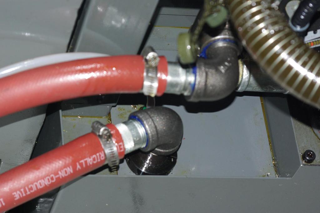
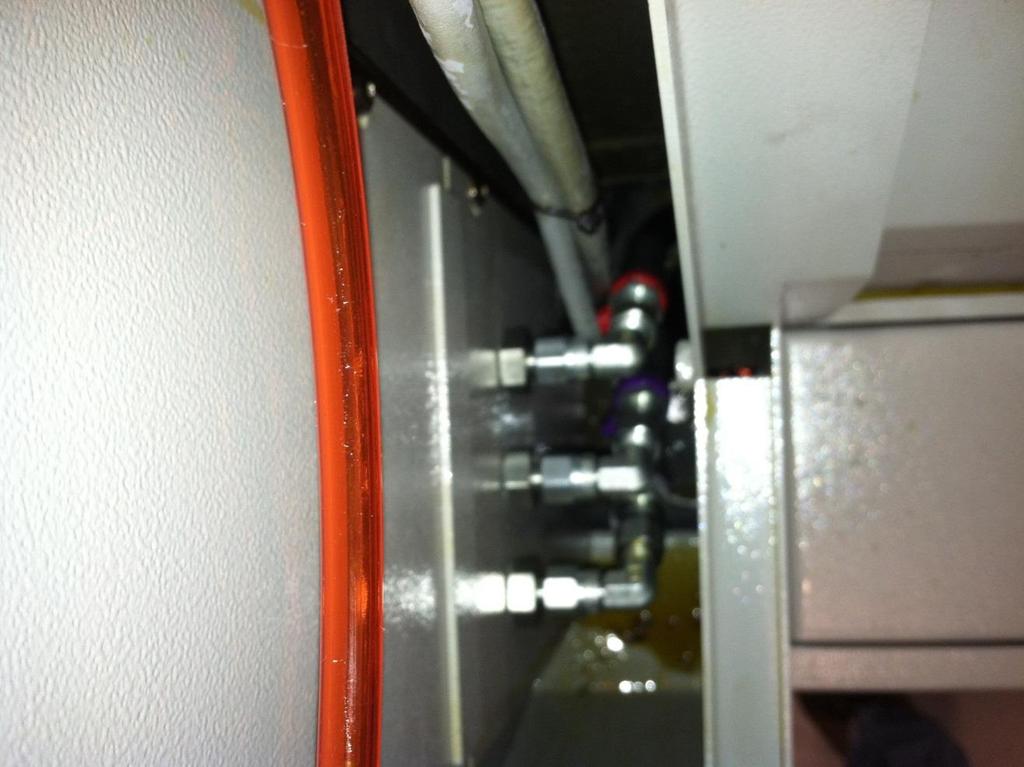
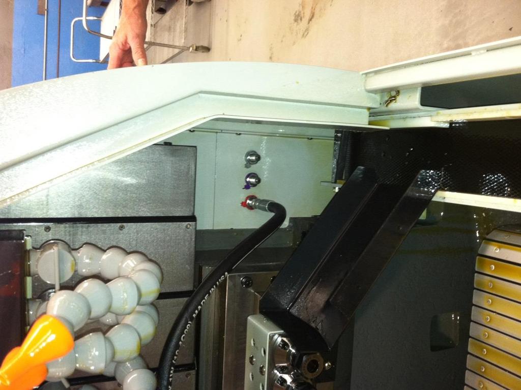
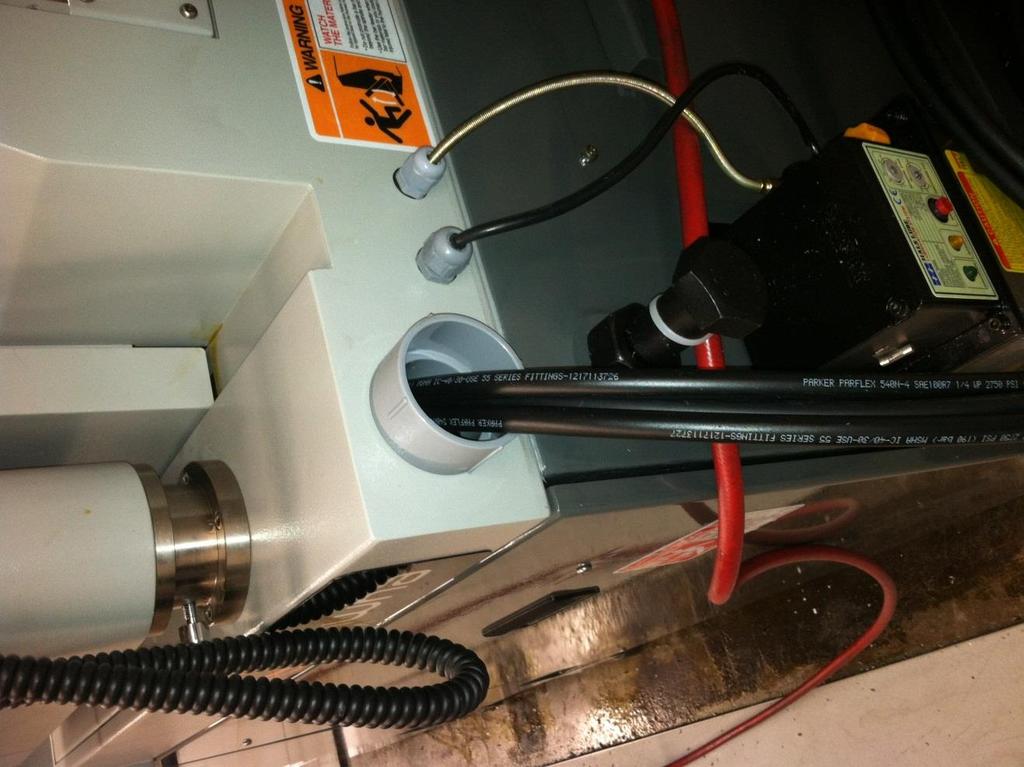
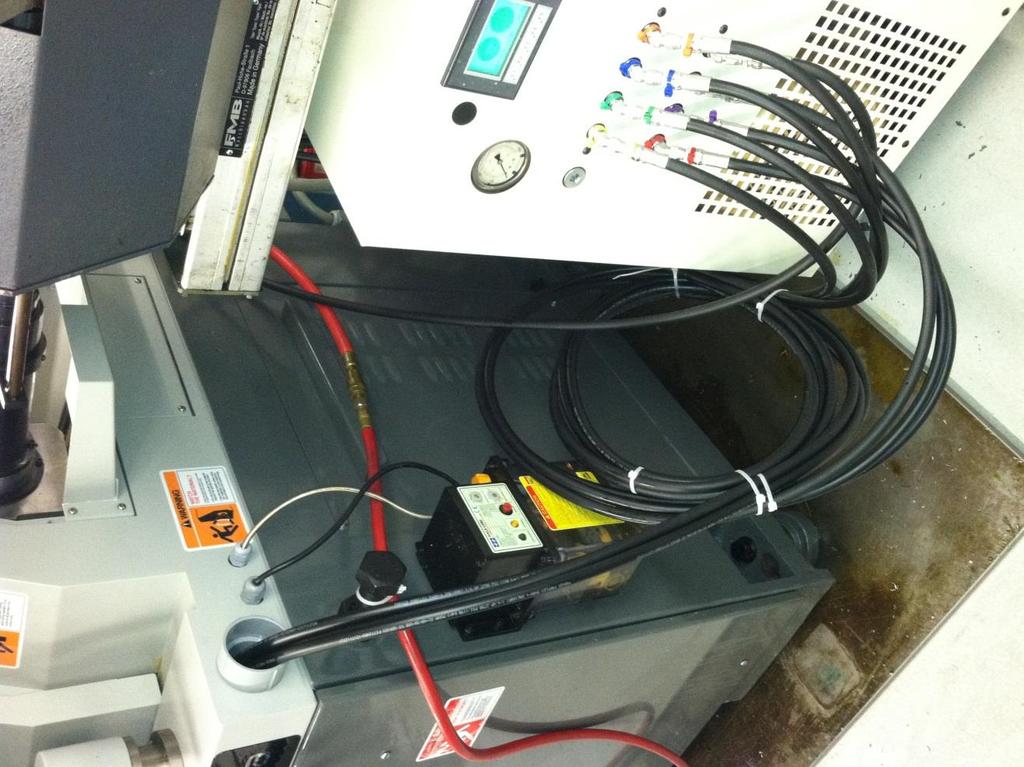
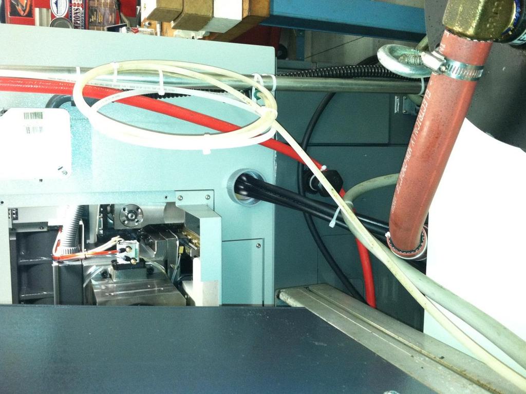
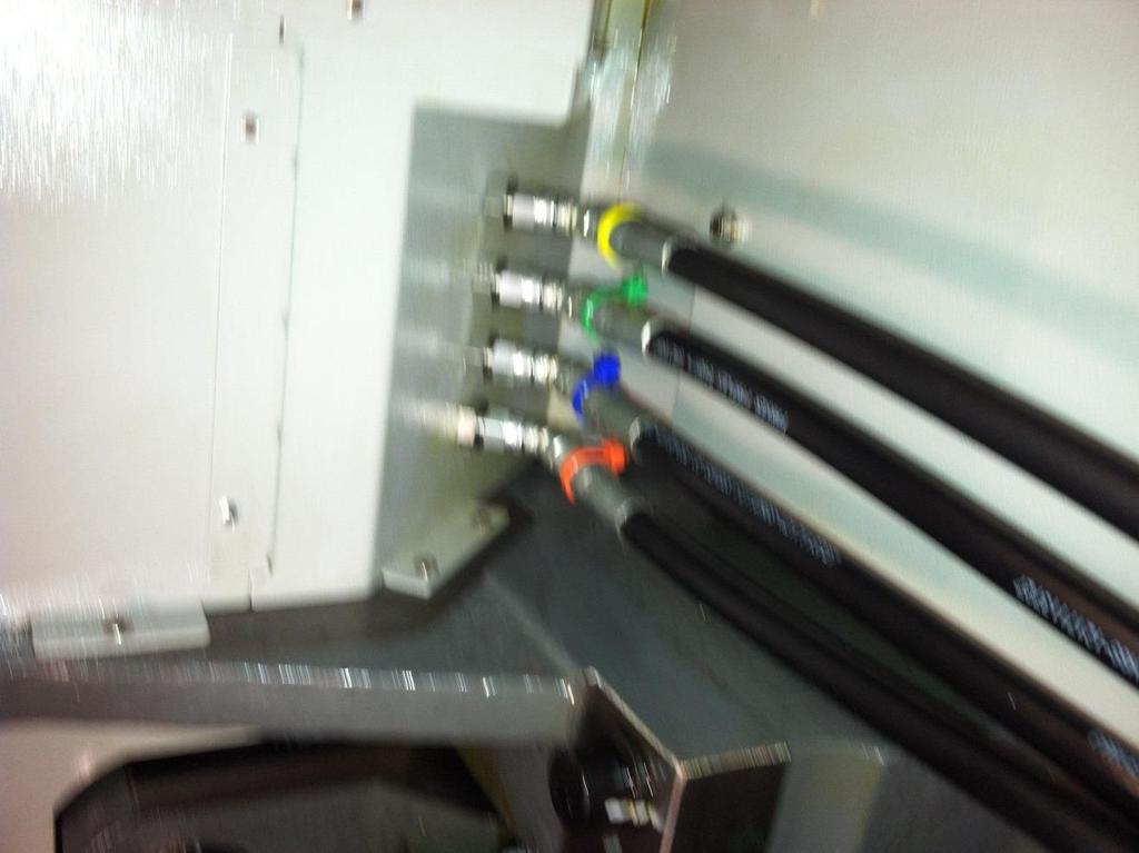
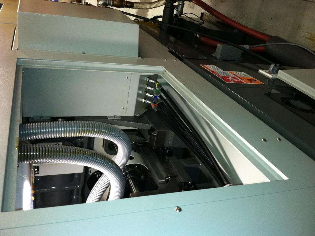
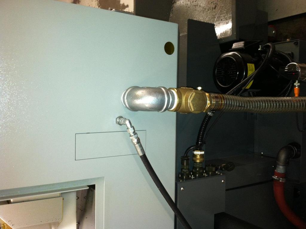
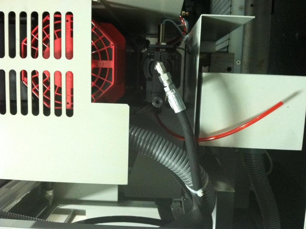
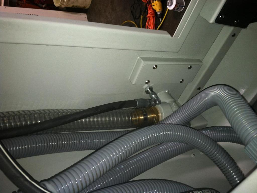
6 M214 #6 light on M215 #6 light off M216 #7 light on M217 #7 light off M218 #8 light on M219 #8 light off 10. TURN THE MACHINE MAIN POWER OFF BEFORE BEGINNING INSTALLATION. 11. Install bulkhead connectors. See photos to identify gang and backwork panels. Use straight bulkhead connectors on gang and straight bulkhead connecters and 90 degree male/female adaptors on backwork panels. 12. Install 2 bushing. See photo for position. 13. Attached colored wire ties to pump outlets, bulkhead connectors and hoses using the color-coding chart in owners manual. 14. Route and connect all the hoses to the bulkhead connectors and the high-pressure pump. Hose placement is critical and consideration to sharp edges, corners and moving machine components must be given to hose placement to avoid damage to the hoses during normal operation. The hoses will move when they are pressurized. 15. Remove the air line and fitting from the sub spindle ejector tube and replace the fitting with a 1/4 JIC x 1/8 MNPT 90 degree fitting. Be sure that the fitting does not strike the rear cabinet when the ejector is in the home position and the sub spindle is at the maximum Z travel position. 16. Install internal high-pressure hose to the bulkhead connector and ejector fitting. Route the hose along the control-wiring path. 17. Install all remaining internal high-pressure hoses. 18. VERIFY THAT ALL THE HOSE CONNECTIONS ARE TIGHT. 19. Install a tee and hose barb between the flood coolant pump and the flexible flood coolant line. Use teflon tape on all the threads 20. Assemble 1 hose barb and 1 x 8 nipple to 90 degree elbow. Use Teflon tape on the threads. 21. Install pipe assembly into coolant tank with one split collar on each side of the tank cover. Adjust the length of pipe in the coolant tank tighten the collars. See photo. 6
7 22. Using 1 hose connect the flood coolant outlet from the installed tee to the inlet of the high pressure pump and tighten the clamps 23. Using 1 hose connect return from the installed polypropylene bulkhead to the outlet of the high-pressure pump and tighten the clamps. 24. Install pressure relief valve in port next to high pressure outlets. 25. TURN THE HIGH PRESSURE DISCONNECT OFF. OPEN ELECTRICAL ENCLOSURE AND TURN OFF THE TWO CIRCUIT BREAKERS. 26. Using a qualified technician, electrically connect the high pressure pump to the power supply. 27. Verify the voltage at the disconnect of the high-pressure pump. 28. Turn on the high pressure disconnect and the 2 pole circuit breaker and verify the voltage and the line side of the 2 pole circuit breaker. THIS MUST BE 208/220 VOLTS LINE TO LINE FOR 220 VOLT SERVICE. 460/480 VOLT LINE TO LINE FOR 460 VOLT SERVICE. 29. Turn on the 1 pole circuit breaker and verify that the PLC run light is on. 30. Turn the pressure relief valve counter clockwise to the stop. 31. Verify the rotation of pump motor -Remove orange cover from coupler -An arrow on the pump indicates the direction the motor/pump should turn -Manually push the starter in the electrical panel and verify the motor/pump is turning in direction of the arrow -Replace the coupler housing cover 32. Verify direction of heat exchanger fan. It should be blowing out through the cooler. 33. Close electrical cabinet door, lock and turn on disconnect. 34. Connect the 24 pin connector to the mating jack on the CNC. 35. Power up the CNC. 36. Open the drain valve, turn on the flood coolant and run for 1 minute. Close the drain valve, leave flood coolant on, and check for leaks. Run flood coolant until a steady flow of oil runs thru purge line. The pump is now primed. 37. MDI sub spindle high-pressure line M218, M219 on 8 line pump or M209, M210 on a 4 line pump. Single block first M code and turn pressure relief valve clockwise to raise pressure to 500 PSI. Run for 1 minute to flush the system. Check for leaks. Single block last M code. 38. Perform the installation checklist, initial, date and sign. 39. The warrantee will be void without a signed copy of the installation checklist returned to the vendor. 7
8 The unit is M-code driven USE Alarms are designed to permit the user to anticipate low pressure conditions and perform maintenance prior to the unit shutting down the machine due to an E-Stop activation. -A yellow indicator light on the pump cabinet notifies the operator that pressure is dropping due to the filter bag accumulating chips. This condition should be corrected at this time. When the bag is changed, the indicator will not light again until the condition reoccurs. -In the event a clogged filter bag significantly impedes the flow of coolant, the pump will activate an E-Stop condition and the red filter reset light will go on. The filter must be changed at this time. When the bag is changed the filter reset must be pushed to clear the alarm. Other conditions that will alarm/e-stop the machine. -Thermal overload of pump motor -Lack of air flow to the coolant unit -Open machine cabinet door INDICATOR LAMP STATUS LAMP CONDITION CAUSES/ACTION Green Pump is running Normal operation Yellow Output filter pressure Change filter media is below 5 PSI Solid Red Alarm Thermal Overload Phase lose Short circuit Motor overload Reset thermal relay Red Reset Clogged filter Change filter media Push reset button Red Reset High pressure below Low coolant supply w/flashing Alarm 50 PSI Clogged coolant supply line Damaged pump coupling Output exceeds capacity Low voltage Pressure set below 425 PSI Push reset button 8
9 FOLLOWING INSTALLATION THE FOLLOWING CHECKLIST MUST BE COMPLETED PRIOR TO PLACING THE HP COOL TECH,INC INC. HIGH PRESSURE PUMP INTO SERVICE. CHECK FOR / RESOLVE LEAKS THROUGHOUT TESTING. # TEST FUNCTION VERIFIED BY 1 Fan Rotation 2 Motor Rotation 3 Bag filter in place, cover secured 4 All lines properly connected 5 Check for leaks, resolve as needed 6 MAIN SPINDLE- MDI mode Program: M218; EOB CYCLE START verify through sub spindle coolant is operational, check for leaks 7 With coolant running, slowly open spindle door, verify high pressure pump shuts off. Repeat process with main door. 8 MAIN SPINDLE- MDI mode Program: M218; EOB CYCLE START shut off coolant flow at operator panel, verify pump stops 9 1. Flood Coolant Pump OFF 2. Cycle start High Pressure Pump (M218) 3. Verify the control generates M code finish error after time out 10 Verify the high pressure pump shuts off along with the flood coolant via the following commands: 1. M9 (MDI Mode) 2. -Coolant off- hard key 11 Verify the high pressure pump shuts off when RESET hard key is depressed. 12 In Automatic Mode, with either door OPEN: -Verify machine will not cycle -Verify door must be closed and RESET hard key is pressed before machine will cycle 13 With high pressure pump ON, depress E-STOP hard key, verify high pressure pump turns off 14 VERIFY FUNCTION OF HP OIL LINES IN BOTH MAIN AND SUB PROGRAMS, CHECK OFF AS VERIFIED LINE COLOR CODE VERIFIED BY 15 M204 On (Main) YELLOW 16 M205 Off (Main) 17 M206 On (Main) GREEN 18 M207 Off (Main) 19 M208On (Main) BLUE 20 M209Off (Main) 21 M210 On (Main) ORANGE 22 M211 Off (Main) 23 M212 On (Main RED # TEST FUNCTION COLOR CODE VERIFIED BY 9
10 24 M213 Off (Main) 25 M214 On (Main) PURPLE 26 M215 Off (Main) 27 M216 On (Main) GREY 28 M217 Off (Main) 29 M218 On (Main) BLACK 30 M219 Off (Main) 31 M204 On (Sub) YELLOW 32 M205 Off (Sub) 33 M206 On (Sub) GREEN 34 M207 Off (Sub) 35 M208On (Sub) BLUE 36 M209Off (Sub) 37 M210 On (Sub) ORANGE 38 M211 Off (Sub) 39 M212 On (Sub) RED 40 M213 Off (Sub) 41 M214 On (Sub) PURPLE 42 M215 Off (Sub) 43 M216 On (Sub) GREY 44 M217 Off (Sub) 45 M218 On (Sub) BLACK 46 M219 Off (sub) 10
11 FOLLOWING INSTALLATION THE FOLLOWING CHECKLIST MUST BE COMPLETED PRIOR TO PLACING THE HP COOL TECH, INC. HIGH PRESSURE PUMP INTO SERVICE. CHECK FOR / RESOLVE LEAKS THROUGHOUT TESTING. # TEST FUNCTION VERIFIED BY 1 Fan Rotation 2 Motor Rotation 3 Bag filter in place, cover secured 4 All lines properly connected 5 Check for leaks, resolve as needed 6 MAIN SPINDLE- MDI mode Program: M218; EOB CYCLE START verify through sub spindle coolant is operational, check for leaks 7 With coolant running, slowly open spindle door, verify high pressure pump shuts off. Repeat process with main door. 8 MAIN SPINDLE- MDI mode Program: M218; EOB CYCLE START shut off coolant flow at operator panel, verify pump stops 9 1. Flood Coolant Pump OFF 2. Cycle start High Pressure Pump (M218) 3. Verify the control generates M code finish error after time out 10 Verify the high pressure pump shuts off along with the flood coolant via the following commands: 1. M9 (MDI Mode) 2. -Coolant off- hard key 11 Verify the high pressure pump shuts off when RESET hard key is depressed. 12 In Automatic Mode, with either door OPEN: -Verify machine will not cycle -Verify door must be closed and RESET hard key is pressed before machine will cycle 13 With high pressure pump ON, depress E-STOP hard key, verify high pressure pump turns off 14 VERIFY FUNCTION OF HP OIL LINES IN BOTH MAIN AND SUB PROGRAMS, CHECK OFF AS VERIFIED LINE COLOR CODE VERIFIED BY 15 M204 On (Main) YELLOW 16 M205 Off (Main) 17 M206 On (Main) GREEN 18 M207 Off (Main) 19 M208On (Main) BLUE 20 M209Off (Main) 21 M210 On (Main) ORANGE 22 M211 Off (Main) 23 M212 On (Main RED # TEST FUNCTION COLOR CODE VERIFIED BY 24 M213 Off (Main) 11
12 25 M214 On (Main) PURPLE 26 M215 Off (Main) 27 M216 On (Main) GREY 28 M217 Off (Main) 29 M218 On (Main) BLACK 30 M219 Off (Main) 31 M204 On (Sub) YELLOW 32 M205 Off (Sub) 33 M206 On (Sub) GREEN 34 M207 Off (Sub) 35 M208On (Sub) BLUE 36 M209Off (Sub) 37 M210 On (Sub) ORANGE 38 M211 Off (Sub) 39 M212 On (Sub) RED 40 M213 Off (Sub) 41 M214 On (Sub) PURPLE 42 M215 Off (Sub) 43 M216 On (Sub) GREY 44 M217 Off (Sub) 45 M218 On (Sub) BLACK 46 M219 Off (sub) 12
13 High Pressure Coolant Lines M Code Color Code Tool M204 On YELLOW M205 Off M206 On M207 Off M208On M209Off M210 On M211 Off M212 On M213 Off M214 On M215 Off M216 On M217 Off M218 On M219 Off GREEN BLUE ORANGE RED PURPLE GRAY BLACK OPERATOR NOTES: 13
14 Hanwha XD20 26 and 32 Backup Procedure BACK UP PROCEDURE MUST BE PERFORMED PRIOR TO MAKING ANY CHANGES TO LADDER PROGRAM OR KEEP RELAYS Press Set/OFS to setting parameter Page + or to (I/O channel) set to 4, if not 4, press #4 then input Insert memory card Press Edit key Press System key Press + soft key to PMC MAINTE Press I/O soft key Select Memory Card Write Parameter Press OPRT soft key Press New Name soft key. Make sure file name is created. Write down file name. Press EXEC soft key. Status will change from writing to complete. Select Memory Card Write Sequence Program Press New Name soft key. Make sure file name is created. Write down file name. Press EXEC soft key. Status will change from writing to complete. Remove card 14
15 Hanwha XD20 and 26 Keep Relay and Ladder Modifications KEEP RLAY Press Edit Key Press System Key Press + soft key to PMC MAINTE Press + soft to Keep Relay Press Keep Relay soft key Change keep relays as required. See installation manual for keep relay settings. PMC LADDER Press System Key Press + soft key to PMC LADDER Press OPRT soft key Press Edit soft key Press + soft key to Stop Press Yes soft key Keyboard type X57.0 Press Search soft key. Make a note of the line number for X57.0. Press Next soft key. Make a note of the line number for X57.0 Again press Next soft key. Make a note of the line number for X57.0 Press Exit soft key Highlight X57.0 on first recorded line number Press Zoom soft key Change X57.0 from N.O. to N.C. Press + soft key to Exit Zoom Press Exit Zoom soft key Highlight X57.0 on second recorded line number Press Zoom soft key Change X57.0 from N.O. to N.C. Press + soft key to Exit Zoom Press Exit Zoom soft key Highlight X57.0 on third recorded line number Press Zoom soft key Change X57.0 from N.O. to N.C. Press + soft key to Exit Zoom Press Exit Zoom soft key Press Exit Edit soft key Press Yes soft key Press Edit soft key Press + soft key to Run Press Yes soft key Press Exit Edit soft key 15
16 16

17 17
18 18
19 19

20 20
21 21
22 22
23 23
24 24
25 VARIABLE HMI OPTION TOUCH SCREEN Run/Filter Warning will display when the pump is running Change Filter Bag on the HMI notifies the operator that the coolant pressure is dropping due to the filter bag accumulating chips. This condition should be corrected at this time. When the bag is changed, the indicator will not light again until the condition reoccurs. Filter Reset. In the event a clogged filter bag significantly impedes the flow of coolant, the pump will activate an E-Stop condition and the Filter Reset light will go on. The filter must be changed at this time. When the bag is changed the filter reset must be pushed to clear the alarm. Press Reset In the event of low pressure output, (below 50 PSI), the pump will activate and E-Stop condition and the Press Reset light will go on. Causes: Clogged coolant supply line Damaged pump coupling Volume output exceeds capacity Low voltage Pressure set below 50 PSI Resolve the cause and press the Press Reset button. Inverter Reset In the event of an inverter fault the pump will activate an E-Stop condition and the Inverter Reset light will go on. See the drive manual for the alarms. Resolve the condition and press the Inverter Reset button 25
26 Each port has two M-Code assigned. Even M-Codes turn the port on, odd M- Codes turn the port off. Press the Next or Prev F key to scroll thru the screens. Select the M-Code to set a pressure and touch the large block and a keyboard will appear. Type in the desired pressure and press ENT key. The pressure can be changed will the pump is running. 26
HP COOL TECH, INC. COOLANT PUMP. PowerPump. OPREATIONS MANUAL Series 10000/11000
 HP COOL TECH, INC. COOLANT PUMP PowerPump OPREATIONS MANUAL Series 10000/11000 1 TABLE OF CONTENTS Page Topic 3 Introduction 3 Specifications 3 Warning 4 Safety 5 Use 6 Filter Replacement Procedure 7 Operator
Instruction Sheet. 1/2 HP Portable Electric Pumps SAFETY FIRST. L2062 Rev. F 02/ IMPORTANT RECEIVING INSTRUCTIONS 2.
 Instruction Sheet 1/2 HP Portable Electric Pumps L2062 Rev. F 02/12 Index: English:...................................... 1-7 Français:.................................... 8-14 Deutsch:...................................
Professional Series 1/2HP 2 YEAR WARRANTY CONVERTIBLE JET PUMP REPAIR PARTS
 Model T033 CONVERTIBLE JET PUMP /HP 900 GPH Suction lift Head of 5 (7.5m) in shallow well mode Professional Series YEAR WARRANTY Suction: /4 Discharge: NPT Maximum pressure: 85 PSI US GPH LPH 5 900 3400
Haas Hydraulic Power Unit - Troubleshooting Guide
 Haas Technical Documentation Haas Hydraulic Power Unit - Troubleshooting Guide Scan code to get the latest version of this document Translation Available A: Haas HPU for most lathes made before 2016. B:
Modulating Furnace Information. Warning on Meter Setting - Read First!
 Modulating Furnace Information Pressure Transducer Pressure DC Volts 0.00" 0.25 0.20" 0.63 0.25" 0.72 0.30" 0.82 0.35" 0.91 0.40" 1.00 0.45" 1.09 0.50" 1.19 0.55" 1.28 0.60" 1.38 0.65" 1.47 0.70" 1.56
Installation Instructions
 Installation Instructions for 15912 to 15916 Electric Fuel Pumps & Fuel Pressure Regulators Installation Instructions WARNING! These instructions must be read and fully understood before beginning the
MODEL SS INSTALLATION INSTRUCTIONS
 WWW.BURCAM.COM 2190 Boul. Dagenais West TEL: 514.337.4415 LAVAL (QUEBEC) FAX: 514.337.4029 CANADA H7L 5X9 info@burcam.com Your pump has been carefully packaged at the factory to prevent damage during shipping.
K10 Intrinsically Safe Electro-Pneumatic Positioner Operating Manual
 K0 Intrinsically Safe Electro-Pneumatic Positioner Operating Manual Pneumatic Connection Outlet Port Gauge Single Acting Actuator (Spring Return): For single acting actuators Outlet Port 2 is to be plugged.
M Installation Guide. PRECISION Manifold Series. Introduction. A. Assemble Manifold Components
 Page 1 Introduction The M-8200 Precision Manifolds are designed for use in Hydronic radiant panel heating and cooling applications. They are available in various sizes, configurations, and options with
Model T Professional Series 1/2HP 2 YEAR WARRANTY SHALLOW WELL JET PUMP
 Model T03121 SHALLOW WELL JET PUMP Professional Series 2 YEAR WARRANTY 1/2HP 916 GPH Head of 25 (7,5 m) US GPH LPH Suction: 1 1/4 NPT Discharge: 1 NPT Maximum Pressure: 65 PSI Stainless steel shaft and
TRIPLE FOAM INSTALLATION MANUAL Part # FOAMSTRMRTPL00X
 TRIPLE FOAM INSTALLATION MANUAL Part # FOAMSTRMRTPL00X TABLE OF CONTENTS Equipment Specifications Page: 1 Suggested Tools and Installation Materials Page: 2 Installation Instructions Page: 2 Initial Start-Up
INSTALLATION INSTRUCTIONS
 www.burcam.com 2190 Dagenais Blvd.West TEL: 514.337.4415 LAVAL (QUEBEC) FAX: 514.337.4029 CANADA H7L 5X9 info@burcam.com INSTALLATION INSTRUCTIONS MODEL 506518SS AND BY-PRODUCTS LIKE Your pump has been
PeroxiDraw Dispenser
 The PeroxiDraw Dispensing System is a locking dispensing system that allows the user to dispense Green Earth Peroxide Cleaner for up to six different dilutions and applications safely and effectively.
WARCO CHEMAG SERIES GH FILTERS
 WARCO CHEMAG SERIES GH FILTERS High Performance Pleated & Bag Type Filtration Systems INSTALLATION, OPERATION, AND MAINTENANCE INSTRUCTIONS Thank you for your purchase of a WARCO Series GH Filtration System.
INSTALLATION INSTRUCTIONS
 www.burcam.com 2190 Dagenais Blvd.West TEL: 514.337.4415 LAVAL (QUEBEC) FAX: 514.337.4029 CANADA H7L 5X9 info@burcam.com Your pump has been carefully packaged at the factory to prevent damage during shipping.
ELECTRIC FUEL PUMPS P/N , , & FUEL PRESSURE REGULATOR P/N
 ELECTRIC FUEL PUMPS P/N 80000100, 80000101, & 80000102 FUEL PRESSURE REGULATOR P/N 80000103 Installation Instructions 199R10583 These instructions must be read and fully understood before beginning the
SECTION B1: MACHINE COMPONENTS
 SECTION B1: MACHINE COMPONENTS The machine portion of the Injected Metal Assembly system provides the means for: holding, heating and injecting the alloy; distributing and controlling electrical, pneumatic,
IVTM Installation Manual
 Integrated Vehicle Tire Pressure Monitoring IVTM Installation Manual 2nd edition Copyright WABCO 2006 Vehicle Control Systems An American Standard Company The right of amendment is reserved Version 002/06.06(us)
VARNA Products 15 GPM (57 LPM) Prelube Kit for MTU 4000 Series Marine Engines
 Prelube Kit for MTU 4000 Series Marine Engines") VARNA Products 15 GPM (57 LPM) Prelube Kit for MTU 4000 Series Marine Engines Installation and Users Manual For the following Prelube Kits: VARNA Products P/N 6423 Kit for 208 VAC 3 Phase VARNA Products
VARNA Products 15 GPM (57 LPM) Prelube Kit for MTU 4000 Series Marine Engines Installation and Users Manual For the following Prelube Kits: VARNA Products P/N 6423 Kit for 208 VAC 3 Phase VARNA Products
AIR/HYDRAULIC INJECTION GUN MODEL INSTRUCTIONS
 I. OPERATION & DESCRIPTION The Air / Hydraulic Injection Gun is a high-pressure tool that should be used with caution and according to these instructions. IMPORTANT: The Gun is 0,000 psi rated. Do not
Power Operated Retrofit Kit for Manual Door 230 VAC or 440/480 VAC 50/60 Hz Installation and Setup Manual
 Therm-L-Tec Building Systems LLC Therm-L-Tech Power Operated Retrofit Kit for Manual Door 230 VAC or 440/480 VAC 50/60 Hz Installation and Setup Manual Rev. A 10/2014 Index Index 1 Electrical Requirements
DEMA BLEND CENTER MODEL 681GAP-3 INSTALLATION INSTRUCTIONS
 1. PARTS CHECKLIST: A. Blend Center Assembly B. Vinyl Supply Tubing with Foot Valve Assembly C. Ceramic Weight D. Vinyl Outlet Tubing E. Screw and Anchor Kit F. Label Card G. Metering Tip Kit 2. INSTALLATION:
Operating Manual Model 3023
 Operating Manual Model 3023 1210 Toovey Road Kelowna, BC Canada V1X 6R4 Phone 250.765.9452 joeh@fluidservicetech.com SAFETY PRECAUTIONS BEFORE STARTING VEHICLE, BE SURE ALL HOSES AND ATTACHMENTS ARE CLEAR
AIR CLEANERS Model MC 3000 OWNER S MANUAL CAUTION Read complete instructions before operating. Please file for future reference.
 AIR CLEANERS Model MC 3000 OWNER S MANUAL CAUTION Read complete instructions before operating. Please file for future reference. MODEL MC 3000 SPECIFICATION Input Volts: 208-230/430 VAC, 60Hz, 3 Phase
INSTALL MANUAL. FOR ON LINE ORDERING- E Commerce Visit Our Website
 INSTALL MANUAL FOR ON LINE ORDERING- E Commerce Visit Our Website WWW.PRESSUREGUARD.COM Contact Information Technical Support: Chris@pressureguard.com Sales Support: Sales@pressureguard.com By Phone: 615-227-6024
Intended Use: Explanation of Signal Word Consequences
 SAFETY INFORMATION & INSTRUCTION MANUAL Please read, understand, and follow all safety information contained in these instructions prior to the use of this device. Retain these instructions for future
Installation & Operating Manual
 Installation & Operating Manual 25IPCC-M 7/08 Edition PC Series C E N T R I F U G A L Congratulations On Your Choice In Purchasing This Webtrol Pump Its Quality is unsurpassed in material and workmanship
Reverse Osmosis System
 Reverse Osmosis System Service Manual 5842 W 34th St, Houston, TX 77092 1.800.999.9878 1.713.683.9878 www.colemanhanna.com Find us on Facebook: /ColemanHannaCarwash HANNA REVERSE OSMOSIS SYSTEMS Table
Not required for most applications. Not required for most applications. High pressure ( provided) High pressure ( provided)
 High pressure ( provided)") ELECTRIC FUEL PUMPS P/N 12-801-1, 712-801-1, 12-802-1, 12-802-2, 712-802-1, 12-812, 12-815-1, & 712-815-1 FUEL PRESSURE REGULATORS P/N 12-500, 12-501, 12-803, 12-803BP, 12-804, & 15812NOS Installation
ELECTRIC FUEL PUMPS P/N 12-801-1, 712-801-1, 12-802-1, 12-802-2, 712-802-1, 12-812, 12-815-1, & 712-815-1 FUEL PRESSURE REGULATORS P/N 12-500, 12-501, 12-803, 12-803BP, 12-804, & 15812NOS Installation
INSTALLATION INSTRUCTIONS MODELS S S SHALLOW WELL & CONVERTIBLE JET PUMPS PAGE 3 PAGE 8
 INSTALLATION INSTRUCTIONS WWW.BURCAM.COM 2190 Blvd. Dagenais West LAVAL (QUEBEC) CANADA H7L 5X9 MODELS 503132S 503332 503232S 503732 TEL : 514.337.4415 FAX : 514.337.4029 info@burcam.com Your pump has
Cleaning Systems Inc. 2 P Rev:03
 CHEMPOD Table of Contents Overview... 3 Specifications... 3 Dimensions... 3 Weight... 3 Electrical Voltage... 3 Capacity... 3 Product Supply... 3 Pneumatic Supply... 3 Optional Installation Kits... 3 Locating
Self Cleaning Hood System Installation, Operation, and Maintenance Manual
 Self Cleaning Hood System Installation, Operation, and Maintenance Manual RECEIVING AND INSPECTION Upon receiving unit, check for any interior and exterior damage, and if found, report it immediately to
Therm-L-Tec Building Systems LLC. Therm-L-Tech. Power Operated Retrofit Kit 230 VAC or 440/480 VAC 50/60 Hz Installation and Setup Manual
 Therm-L-Tec Building Systems LLC Therm-L-Tech Power Operated Retrofit Kit 230 VAC or 440/480 VAC 50/60 Hz Installation and Setup Manual Rev. A 01/2015 Index Index 1 Electrical Requirements for Therm-L-Tec
ValveMate 7000 Controller Operating Manual
 A NORDSON COMPANY ValveMate 7000 Controller Operating Manual Steady Test Clear Time Set Fast Slow POWER RUN SETUP CYCLE A NORDSON COMPANY VALVEMATE 7000 Run Setup Purge Program Fast Slow Time Set Pressure
NECO Pumping Systems
 INSTALLATION OPERATION & MAINTENANCE INSTRUCTIONS For Your NECO Pumping Systems PACKAGED CIRCULATING SYSTEM THIS COMPLETELY ASSEMBLED, TESTED, PACKAGED CIRCULATING SYSTEM IS OF THE HIGHEST QUALITY AND
Aqua-Clear Fiberglass Sand Filters
 Aqua-Clear Fiberglass Sand Filters Addendum to the Installation & Users Guide Automatic Backwash Filter Assembly See Installation & User s Guide for important Safety Instructions System Contents... 3 Overview...
Operations Manual. Automated Fuel Maintenance System FUEL TECHNOLOGIES INTERNATIONAL
 Operations Manual Automated Fuel Maintenance System FTI-10A & 20A FUEL TECHNOLOGIES INTERNATIONAL Replacement Manuals Available on Website: www.fueltechnologiesinternational.com 07/15/2015 Rev E Fuel Technologies
Operating and Installation Instructions
 Model Number 40401-c (-sp) Electronic Fuel Pump Operating and Installation Instructions This Product is Patent Pending. Application available upon request CAUTION! This product is to be installed only
Kit. Hydraulic Kit Installation Guide REV A Item Description Part Number Qty
 Hydraulic Kit Installation Guide Item Description Part Number Qty 1. HOSE ASSY. 1/2" X 174" -8F X -8F 90 DEG. ORFS F451TC-JCJ9080808-174 1 2. HOSE ASSY. 1/2" X 96" -8F X -10F ORFS F451TC-JCJC081008-96
Professional Séries. Professional Séries. Model T03828 SUBMERSIBLE SUMP DUPLEX SYSTEM SUBMERSIBLE SUMP DUPLEX SYSTEM. 1/3HP 2400 GPH Head of 20 (6 m)
") Model T0828 Primary pump 1/HP 200 GPH Head of 20 (6 m) SUBMERSIBLE SUMP DUPLEX SYSTEM Professional Séries Discharge: 1 1/2 ABS DWV pipe Electric cable: 9 piggyback type Oil cooled Cast iron construction
Model T0828 Primary pump 1/HP 200 GPH Head of 20 (6 m) SUBMERSIBLE SUMP DUPLEX SYSTEM Professional Séries Discharge: 1 1/2 ABS DWV pipe Electric cable: 9 piggyback type Oil cooled Cast iron construction
MODEL 660 AUTOMATIC FASTENING CENTER OPERATOR S MANUAL
 MODEL 660 AUTOMATIC FASTENING CENTER OPERATOR S MANUAL Copyright: January 13, 2003 Revised: 080612 Serial No. 0506113. 1 TABLE OF CONTENTS INTRODUCTION..3 OPERATOR SAFETY... 3 SYSTEM REQUIREMENTS..4 INSTALLATION
WPS-104 Heater Installation Instructions For 500EFI, 700 XP, & Crew Applications
 WPS-104 Heater Installation Instructions For 500EFI, 700 XP, & Crew Applications ORDER OF INSTALLATION FOR A COMPLETE ENCLOSURE OF A RANGERWARE WPS (Weather Protection System) IS AS FOLLOWS: 1. Heater
Material required for drilled well application (indoor use only)
") SAFETY INSTRUCTIONS: This fine pump that you have just purchased is designed from the latest in material and workmanship. Before installation and operation, we recommend the following procedures: A B C
SAFETY INSTRUCTIONS: This fine pump that you have just purchased is designed from the latest in material and workmanship. Before installation and operation, we recommend the following procedures: A B C
AQUIS Foam System. Installation, Operation, and Maintenance Instructions AQUIS 1.5, AQUIS 3.0, and AQUIS 6.0
 Form Number: F-1031 Issue Date: Aug 1, 2017 Section: 2447 Revision Date: Sept 7, 2018 AQUIS Foam System Installation, Operation, and Maintenance Instructions AQUIS 1.5, AQUIS 3.0, and AQUIS 6.0 Waterous
INSTALLATION INSTRUCTIONS
 INSTALLATION INSTRUCTIONS Universal Air Series!! NOTE!! Covers the following model: 6000 Series 85-0100B-AZ Rev 0 5/07 To ensure that the system is installed properly, provide your electrician with these
SERIES 700/700E FACTORY KEYLESS UPGRADE INSTALLATION MANUAL
 SERIES 700/700E FACTORY KEYLESS UPGRADE INSTALLATION MANUAL Items Supplied with the System: Installation Instructions: Main unit 1. Mounting the module: Plug In LED Mount the module in a suitable location
Eclipse GEN 2.0 CAFSystem, Model 150-ESECL as used with TC20 Series PTO Installation Instructions
 Eclipse GEN 2.0 CAFSystem, Model 150-ESECL as used with TC20 Series PTO Installation Instructions Read Read through the the safety installation information instructions overhaul carefully instructions
Eclipse GEN 2.0 CAFSystem, Model 150-ECL CAFS PTO Kit Installation Instructions
 Eclipse GEN 2.0 CAFSystem, Model 150-ECL CAFS PTO Kit Installation Instructions Read Read through the the safety installation information instructions overhaul carefully instructions before carefully beginning
 Operation and Maintenance Manual http://www.torsionx.eu Use the MaxDrv Series Square Drive Torque Wrench Model.75, 1, 3, 5, 8, 10, 20, 25, 35, 50 to install and remove threaded fasteners requiring precise
Coolant Purification Systems Ultra 360 INSTRUCTION MANUAL
 Coolant Purification Systems Ultra 360 INSTRUCTION MANUAL Model: Ultra 360 Serial No. Manufacture Date: Revision: M Unit Footprint & Layout Description of each component Installation Guide Before starting
Manifold Isolation Valves
 300 N. Opdyke Rd. Introduction The Stainless Manifolds are designed for use in Hydronic radiant panel heating and cooling applications. They are available in various sizes, configurations, and options
M-8100EP. Installation Guide ENGINEERED PLASTIC MANIFOLD SERIES. Introduction. A. Assemble Manifold Components
 Introduction The Pro Manifolds with Integrated adaptor are designed for use in Hydronic radiant panel heating and cooling applications. They are available in various sizes, configurations, and options
DEMA BLEND CENTER MODELS: 637GAP-1 and 637GAP-4 INSTALLATION INSTRUCTIONS
 1. PARTS CHECKLIST: ITEM DESCRIPTION QTY. A. Blend Center Assembly 1 B. ¼ ID X 8 Long Vinyl Supply Tubing & Foot Valve Assembly 4 C. Ceramic Weight 1 D. ½ ID X 6 Long Vinyl Outlet Tubing (For 1 GPM Station
HALLMARK INDUSTRIES INC
 Performance Part No. HP. CONVERTIBLE JET PUMP USER S MANUAL GPH of Water @ Total Discharge Pressure of 40 psi Max. Pressure Max suction (shallow well) Max Suction (deep well) Max GPM (@0 head) Max Discharge
Val-Matic Air / Oil Hydraulic Panel Pump Control System. Operation, Maintenance and Installation Manual
 Manual No. 5AOP-OM1-2 Val-Matic Air / Oil Hydraulic Panel Pump Control System Operation, Maintenance and Installation Manual INTRODUCTION... 1 RECEIVING AND STORAGE... 1 DESCRIPTION OF OPERATION... 1 INSTALLATION...
COOKSON OWNER'S MANUAL
 COOKSON OWNER'S MANUAL FDO-A10 INDUSTRIAL DUTY FIRE DOOR OPERATOR R L I S T E D 3040233 US CONTROL PANEL SERIAL# OPERATOR SERIAL# 9001.DWG ECN 0959 REV 4 SPECIFICATIONS MOTOR TYPE:...INTERMITTENT HORSEPOWER:...1/8
TWO-STAGE HYDRAULIC PUMP. RWP55-IBT-Air
 ORIGINAL INSTRUCTIONS Form No.1000458 5 SPX Corporation 5885 11th Street Rockford, IL 61109-3699 USA Tech. Services: (800) 477-8326 Fax: (800) 765-8326 Order Entry: (800) 541-1418 Fax: (800) 288-7031 Internet
IBT Series Square Drive Torque Wrenches
 IBT Series Square Drive Torque Wrenches Operation and Maintenance Manual Model.75, 1, 3, 5, 8, 10, 20, 25, 35, 50 http://www.torsionx.com Use the IBT Series Square Drive Torque Wrenches Model.75, 1, 3,
Steam/Water Washdown Units Safety and Operation Installation and Maintenance Instructions
 INSTALLATION AND MAINTENANCE INSTRUCTIONS IM-8-002-US October 2016 Steam/Water Washdown Units Safety and Operation Installation and Maintenance Instructions These instructions should be read by the Company
MODEL 25-OM-10-C & 25-OA-10-C HYDRAULIC BOOSTER
 SPX Corporation 5885 11th Street Rockford, IL 61109-3699 USA Internet Address: http://www.powerteam.com Tech. Services: (800) 477-8326 Fax: (800) 765-8326 Order Entry: (800) 541-1418 Fax: (800) 288-7031
Maintenance Manual. Automated Fuel Maintenance System FTI-5A SINGLE TANK FUEL TECHNOLOGIES INTERNATIONAL
 Maintenance Manual Automated Fuel Maintenance System FTI-5A SINGLE TANK FUEL TECHNOLOGIES INTERNATIONAL 05/01/2016 Rev A Fuel Technologies FTI-5A Single Tank Maintenance Section FTI - Fuel Maintenance
Coolant Purification Systems Ultra 360 INSTRUCTION MANUAL
 Coolant Purification Systems Ultra 360 INSTRUCTION MANUAL Model: Ultra 360 Serial No. Manufacture Date: Revision: E September 2016 Unit Footprint & Layout Description of each component Installation Guide
POWER PINNER RAPID FIRE 7005 RF OPERATOR S MANUAL
 POWER PINNER RAPID FIRE 7005 RF OPERATOR S MANUAL Copyright: February 20, 2007 Revised: 12-11-2015. Gripnail Corporation An Employee Owned Company 97 Dexter Road East Providence, Rhode Island 02914-2045
3 FT CORD Models , , , FT CORD W/GFCI Models , , ,
 POWERLINE XP II Swimming Pool Pump (Light Oak color model) With Automatic Timer 3 FT CORD Models 0-1395-226, 0-1396-226, 0-1397-226, 0-1398-226 25 FT CORD W/GFCI Models 0-1395-220, 0-1396-220, 0-1397-220,
HexPro Series Low Profile Wrenches
 HexPro Series Low Profile Wrenches Operation and Maintenance Manual Model 2HP 4HP 8HP 14HP 30HP www.torquetoolsinc.com Use the HEXPRO Series Low Profile Wrenches Model 2HP 4HP 8HP 14HP 30HP to install
Purging Air From Divider Block Lubrication Systems
 FROST ENGINEERING SERVICE Purging Air From Lubrication Systems A D I V I S I O N O F G E C S E Y S A L E S & S E R V I C E DESCRIPTION Divider block lubrication systems operate correctly only when all
PREPOINT CHAMFER GRINDER MODEL Section 1. Set up and operation
 PREPOINT CHAMFER GRINDER MODEL 6-94 Set up and operation Section 1 1. Installation of the proper size collet. This machine used a 5-C style collet. This can be changed by loosening of he set screw located
Installation Instructions Light Commercial & Irrigation Water Pressure Booster System
 Installation Instructions DuraMAC TM Light Commercial & Irrigation Water Pressure Booster System The DuraMAC TM Water Pressure Booster System is the first booster pump of its kind to be designed for virtually
Startup and Operation of SEE-THRU Nuclear Power Plant for Student Performance MP-SEE-THRU-01 Rev. 018
 Student Operating Procedure Millstone Station Startup and Operation of SEE-THRU Nuclear Power Plant for Student Performance Approval Date: 01/12/2011 Effective Date: 01/12/2011 TABLE OF CONTENTS 1. PURPOSE...3
5000TOC Sensor Service Manual
 Part No. 84449 5000TOC Sensor Service Manual This document contains proprietary information, which is protected by copyright. All rights are reserved. No part of this document may be photocopied (other
Kit. Hydraulic Kit Installation Guide REV A. Item Component Part Number Qty
 Hydraulic Kit Installation Guide Item Component Part Number Qty 1. HOSE ASSY. 3/8" X 110" -8F ORFS X -8F ORFS 90 DEG F451TC-JCJ9080806-110 1 2. HOSE ASSY. 3/8" X 110" -6F ORFS X -8F ORFS 90 DEG F451TC-JCJ9060806-110
Enclosed Electric Rotary Screw Compressor Installation Guide
 Enclosed Electric Rotary Screw Compressor Installation Guide Air compressors should only be installed trained installation personnel call 800-531-9656 to find a local trained. Warning: Read all installation
MINI MANIA REMOTE OIL COOLER INSTALLATION INSTRUCTIONS P/N NME1055
 MINI MANIA REMOTE OIL COOLER INSTALLATION INSTRUCTIONS P/N NME1055 Mini Mania s Cooper S Remote Oil Cooler Kit is designed to reduce operating temperatures by cooling the motor oil using an external radiator.
TABLE 1-1 GPM FLOW RATE PROPORTIONER, 1/4 I.D. TUBING Injection Rates For Viscosities Shown Metering Tip Color
 Blend Safe II Dispensing System is a modular, locking dispensing system that allows user to dispense chemicals safely, control dispenser inventory and has the flexibility in the field to meet changing
Low Profile Wrenches Operation and Maintenance Manual
 Low Profile Wrenches Operation and Maintenance Manual http://www.torquetoolsinc.com Use the HEXPRO Series Low Profile Wrenches Model 2HP 4HP 8HP 14HP 30HP to install and remove large bolts that have minimal
Checker Unload Checkstand Installation Instructions
 Front-End Checkouts Commercial Refrigeration Equipment Display Merchandisers Store Fixtures Checker Unload Checkstand Installation Instructions Attention Store Manager: Please find enclosed in this packet
Operating instructions Form no safety definitions
 Operating instructions Form no. 1000437 safety definitions safety symbols are used to identify any action or lack of action that can cause personal injury. Your reading and understanding of these safety
INSTALLATION INSTRUCTIONS MODELS S S S S SSN S SSW SSN SPRINKLER PUMPS
 WWW.BURCAM.COM 2190 Boul. Dagenais West TEL: 514.337.4415 LAVAL (QUEBEC) FAX: 514.337.4029 CANADA H7L 5X9 info@burcam.com Your pump has been carefully packaged at the factory to prevent damage during shipping.
Gas Engine overheat diagnosis
 Gas Engine overheat diagnosis Introduction... 2 Six Step Troubleshooting Method... 3 Diagnostic Tips... 4 Clear Hose Testing Equipment... 5 Clear Hose Setup (Pump)... 6 Clear Hose Setup (Engine)... 7 Gauge
RUFNEX Series Low Profile Wrenches Operation and Maintenance Manual
 RUFNEX Series Low Profile Wrenches Operation and Maintenance Manual http://www.torsionx.com Use the RUFNEX Series Ultra-Low Profile Wrenches to install and remove large bolts that have minimal wrench clearance.
Section 18: Fuses, Heaters, Parameters
 Section 18: Fuses, Heaters, Parameters March 2003 Section 18: Fuses, Heaters, Parameters 639 640 Section 18: Fuses, Heaters, Parameters March 2003 March 2003 Section 18: Fuses, Heaters, Parameters 641
Healy VP Troubleshooting Guide
 Healy VP1000-5 Troubleshooting Guide Manual # Revision Date Changes from Previous Revision 405291001 2 Mar. 2012 Remove pipe tape brand reference Franklin Fueling Systems 3760 Marsh Rd. Madison, WI 53718
VERTICAL MACHINING CENTER
 VERTICAL MACHINING CENTER Model: TW-1480 (FANUC 0i /32i) OPERATION MANUAL 1 TW-1480 Operation Manual Content CH 1 Description of Operating BOX. 3 1 Description of Operating Box... 3 1-1 Description of
3 FT CORD UL/NEC Models , , , FT CORD w/gfci UL Models , , ,
 POWERLINE XP I Swimming Pool Pump (Light Oak color model) 3 FT CORD UL/NEC Models 0-1295-206, 0-1296-206, 0-1297-206, 0-1298-206 25 FT CORD w/gfci UL Models 0-1295-200, 0-1296-200, 0-1297-200, 0-1298-200
CNC Tool Room Milling Center MODEL: VM-760
 CNC Tool Room Milling Center MODEL: VM-760 MACHINE FEATURES 7.5HP high torque spindle motor, low noise and vibration BT40/CAT40/DIN40 6000 rpm spindle speed, ( Optional 8,000, 10,00, 12,000 or 15,000rpm
INSTALLATION/OPERATION/MAINTENANCE INSTRUCTIONS FOR ARCHON MODELS WD2010L, WD2010, WD2010H WASHDOWN STATIONS. ARCHON Industries, Inc.
 ARCHON Industries, Inc. Washdown Stations Models WD2010L, WD2010, WD2010H Installation / Operation / Maintenance Instructions 1 This manual has been prepared as an aid and guide for personnel involved
Section 10: Rotary Tables
 Section 10: Rotary Tables Rotary Tables, 4th Axis Figure 10-1 Rotary Table Pre-installation Remove the top of the shipping crate: 1) With a large screwdriver gently pry the clips from the bottom of the
Hydraulic Oil Cooler. Assembly Instructions (Originating w/serial Number )
") Hydraulic Oil Cooler Case 465 Skid Steer Assembly Instructions (Originating w/serial Number 50-101) Model Number: Serial Number: Date of Purchase: Specialized Equipment, Inc. 650 So. Main Street - PO Box
Hydraulic Oil Cooler Case 465 Skid Steer Assembly Instructions (Originating w/serial Number 50-101) Model Number: Serial Number: Date of Purchase: Specialized Equipment, Inc. 650 So. Main Street - PO Box
Techcon Systems TS500R-PC Controller For Positive Displacement PC Pump
 Techcon Systems TS500R-PC Controller For Positive Displacement PC Pump Copyright OK International CONTENTS Page Number 1. Safety 3 2. Symbol Definitions.. 3 3. Specifications... 4 4. Features.. 5 5. Setup
# and # FAST Fuel System Kits
 1 INSTRUCTIONS #307500 and #307501 Fuel System Kits Thank you for choosing products; we are proud to be your manufacturer of choice. Please read this instruction sheet carefully before beginning the installation.
Overspeed Adjustable Valve
 Overspeed Adjustable Valve Every attempt has been made to ensure that this documentation is as accurate and up-to-date as possible. However, Vertical Express assumes no liability for consequences, directly
DuraMAC LIGHT COMMERCIAL & IRRIGATION WATER PRESSURE BOOSTER SYSTEM INSTALLATION INSTRUCTIONS
 DuraMAC LIGHT COMMERCIAL & IRRIGATION WATER PRESSURE BOOSTER SYSTEM INSTALLATION INSTRUCTIONS The DuraMAC TM Water Pressure Booster System is the first booster pump of its kind to be designed for virtually
Supported Models: Ag-Chem Terragator 6103, 6203 Ag-Chem Terragator 8103, AutoFarm GPS AutoSteer. Hardware Installation Guide
 Supported Models: Ag-Chem Terragator 6103, 6203 Ag-Chem Terragator 8103, 8203 AutoFarm GPS AutoSteer Hardware Installation Guide P/N: 602-0147-01-A January 2008 Special Requirements Tools This list consists
Medi-Flow. Model M101 & M101D Medicator Instructions GETTING TECHNICAL ASSISTANCE
 UNPACKING Please open and inspect your package upon receipt. Your package was packed with great care and all the necessary packing materials to arrive to you undamaged. If you do find an item that is broken
FPS- 80. Manual. Reverso Pumps, Inc. Ph: (954)
") FPS- 80 Manual Table of Contents System Overview... 1 Control Panel Overview... 2 Technical Specifications... 3 Electrical and Installation... Tank Diagrams... 5 Initial Setup... 6 Digital Timer Instructions:
FPS- 80 Manual Table of Contents System Overview... 1 Control Panel Overview... 2 Technical Specifications... 3 Electrical and Installation... Tank Diagrams... 5 Initial Setup... 6 Digital Timer Instructions:
TECHNICAL DATA. Trimpac 244a. April 15, 2011
 April 15, 2011 Trimpac 244a 1. DEsCrIpTION DESCRIPTION TRIMPAC Model B-1 and B-1B is a factory-assembled trim package with an electric release module in a metal enclosure. The standard trim normally required
 Operation and Maintenance Manual Model.75,, 3, 5, 8, 0, 0, 5, 35, 50 http://www.torsionx.com Use the MaxDrv Series Square Drive Torque Wrench Model.75,, 3, 5, 8, 0, 0, 5, 35, 50 to install and remove threaded
IS7.6 INSTALLATION MANUAL
 IS7.6 INSTALLATION MANUAL #12501 MIN. 13.5" 1" 1" 29-7/8" 3" 14-7/8" 3" 20-7/8" 29-7/8" 24-5/8" Fig. 1 1 2 Fig. 2 Fig. 3 MAX. 80" MIN. 12" IS7.6 MIN. 8" Fig. 4 2 MIN. 6" MIN. 13.5" MIN. 12" MIN. 6" MIN.
JARVIS. Model HTC -80 Hog Toe Cutter
 Model HTC -80 Hog Toe Cutter HTC -80 Standard HTC -80 Pistol Grip EQUIPMENT SELECTION... Ordering No. HTC--80 Standard... 4025061 HTC--80 Pistol Grip... 4025100 HTC--80 Pistol Grip Long... 4025114 without
Installation & Operating Manual
 Installation & Operating Manual 25INV-M 1/17 Edition NV Series Vertical Booster Stainless Steel Multistage Centrifugal Pump Congratulations On Your Choice In Purchasing This Webtrol Pump Its Quality is