A COMPARISON OF THE PERFORMANCE OF LINEAR ACTUATOR VERSUS WALKING BEAM PUMPING SYSTEMS Thomas Beck Ronald Peterson Unico, Inc.
|
|
|
- Diana Day
- 5 years ago
- Views:
Transcription
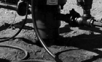
1 A COMPARISON OF THE PERFORMANCE OF LINEAR ACTUATOR VERSUS WALKING BEAM PUMPING SYSTEMS Thomas Beck Ronald Peterson Unico, Inc. ABSTRACT Rod pumping units have historically used a crank-driven walking beam to provide a reciprocating motion for oil and gas production. Several geometries have evolved over the years to produce desirable polished rod motion profiles and gearbox torque loads. These mechanical systems are limited in their ability to manipulate the motion profile, and a given pumping unit profile is forever fixed by the selected geometry. Hydraulic cylinder linear actuators became available a number of years ago for reciprocating rod pumping of oil and gas wells. Electrically driven rack-and-pinion linear actuators have also been recently developed for rod pumping applications. These hydraulic and electric linear pumping units share some common advantages over mechanical pumping units that are examined in this paper. TRANSPORTATION AND INSTALLATION LOGISTICS Linear pumping units are generally less massive than comparable walking beam units and can be mounted directly to the wellhead. The cost savings on site preparation, transportation logistics, and equipment installation can be substantial. Figure 1 shows a dimension diagram for conventional pumping units, and Figure 2 gives the pumping unit stroke, height, width, and length dimensions. Pumping unit dimensions obviously grow with stroke length. Table 1 shows that height, width, and length ratios relative to stroke improve with pumping unit size. Figure 3 shows a simplified dimension diagram of linear rod pumps with the associated dimensions shown in Figure 4. Linear rod pumps with strokes up to 68 inches are rack-and-pinion units driven by electric motors, and the 120-inch stroke unit is an hydraulic-cylinder-based unit. The relative heights of the linear units are similar to walking beam pumping units, but the length and width are considerably smaller. Weights of the various units are difficult to compare, but linear rod pumps often weigh considerably less than mechanical pumping units. The linear rod pumps have shipping weights in the range of 1,000 to 4,000 pounds, depending on stroke length. The relatively small dimensions and weight of linear pumping units can dramatically affect transportation and installation logistics. Transportation of mechanical pumping units generally involves one or more flat bed trailers of equipment like that shown in Figure 5. Getting that equipment into remote hilly regions can be a struggle. As can be seen in Figure 6, the smaller linear pumping units can actually be transported in the back of a pickup truck. The installation of linear rod pumps can generally be completed in less than one day using a service rig, picker truck, or front-end loader. The linear rod pumps with strokes up to 144 inches and polished rod loads up to 30,000 pounds have successfully used direct mounting to the casing as shown in Figure 7. Direct tubing mounts shown in Figure 8 can be used for the smaller linear pumping units. The tubing mount is similar to that used with progressing cavity pumps like that shown in Figure 9, and it simplifies the transition to rod pumping that often proves necessary in coal-bed methane applications. The small size and direct wellhead mount not only minimize ground disturbance but have beneficial effects on aesthetics and safety as well. Figures 10 through 12 show linear rod pump installations in Texas, New Mexico, and Venezuela prior to the removal of the walking beam pumping units they replaced. These figures graphically illustrate the relative size of the linear actuator versus walking beam pumping technologies. These figures also show the potential improvement in well-site appearance for environmentally sensitive areas. Sound levels for linear rod pumps also tend to be substantially less than the mechanical pumping units. Since the
2 only moving part of the linear rod pump is the polished rod, it is substantially safer than walking beam pumps, which have numerous moving components and associated dangerous pinch points. A simple screen around the mounting base can be used to eliminate access to any moving parts and the need for protective fencing or enclosures. The relatively large weights of walking beam pumping units compared to linear rod pumps is due, in large part, to the counterbalance weight and its associated mechanism. The electric linear rod pumps can often be operated without counterbalance due to the relatively shallow depth of the wells appropriate for that technology. Electric units can also make use of drive systems that feed downstroke regenerative energy back to the power line. Air cylinders are also available on electric units like that shown in Figure 13 to provide a counterbalance effect. These cylinders can be designed to serve a dual purpose of providing both counterbalance effect and casing gas compression. That compression can be used to boost casing pressure at the well site in CBM applications and lower backside pressure to improve production on both oil and gas wells. A counterbalance effect can also be achieved on hydraulic units using nitrogen accumulators. PUMPING UNIT ANALYZERS AND SIMULATORS Commercial pumping unit analyzers such as the Rodstar program support linear pumping units like the Rotaflex and DynaPump units. Those modern analysis programs include pumping unit simulation capability. Improvements in computer processing capacity and simulation techniques provide pump performance analysis that closely matches field test results. Figure 14 shows the dynamometer cards measured in the field on a Rotaflex pumping unit. As can be seen in Figure 15, the dynamometer card simulation from a Rodstar analysis program is nearly identical to the measured field results. Similar analysis programs exist for electric linear rod pumps. These analysis programs include a simulator that not only runs on a desktop computer but is also built into the controllers to allow instantaneous comparison of measured and simulated results, such as that shown in Figure 16. PUMPING UNIT MOTION PROFILES Linear actuators also have an important advantage in their ability to provide independent control of up and down stroke peak velocities as well as the shape of the velocity profile. Controlling the velocity profile allows increased pump cycle rate and associated production without exceeding rod fall velocity limits. An analysis program was developed to compare the performance of the linear versus both conventional (Class I) and phased-crank (Class III) pumping units. The motion profile of the mechanical pumps can be calculated from their API dimensions using the method described in the API standard 11E, Specification for Pumping Units, November 1, The motion profile for a linear pump generally has a trapezoidal shape with controlled acceleration through the endpoints. The analysis program input parameters includes mechanical pumping unit dimensions and linear pump acceleration time as a percentage of the pump cycle time. API dimensions for 100-inch stroke pumping units were used as Pumping Unit Parameters in the analysis of both Class I and Class III geometries. A 5,000-foot-deep well with a 76 taper rod design and a inch insert pump was used as System Input Parameters for the analysis for pumping units running at 10 spm. The analysis program produces a number of familiar Calculated Parameters as well as graphical displays of rod velocity and position profiles versus time for both linear actuator and walking beam pumping units. The linear rod pump trapezoid profile will generally have lower peak speeds than the cycloid profile of a walking beam pumping unit due to the ability of the pump to quickly change direction. The faster the acceleration rate through the endpoints or corners, the less speed is required down the straightaway to cover the same rod stroke. This capability of the linear rod pump to cover greater distance for any given peak speed can be used to increase the pump stroking rate and production without exceeding rod fall velocity limits.
3 The analysis program shows graphical results for both linear actuator and walking beam pumping units operating at the same stroking rate and polished rod stroke. Those charts show matched polished rod stroke, but linear rod pump velocities that are generally lower than those of the mechanical pumping unit. Linear rod pump velocity and position profiles are also shown assuming the peak up and down stroke speeds are the same as those of the mechanical pumping unit. That set of charts shows matched peak rod speeds, but linear rod pump polished rod strokes that are generally larger than those of the mechanical pumping unit. Figures 17 through 19 show the results for a conventional pumping unit with Class I geometry along with the results for a linear pumping unit with acceleration times of 75% and 25% of the total cycle time. Figures 20 through 22 show the results for a phased-crank pumping unit with Class III geometry along with the results for a linear pumping unit with acceleration times of 75% and 25% of the total cycle time. The pump speed (Np), plunger stroke (Sp), and fluid production (Qp) are shown in the Calculated Parameters for the mechanical sucker-rod pump (SRP). The pump speed (Npe), plunger stroke (Spe), and fluid production (Qpe) are also shown for the linear rod pump (LRP) for the same up and down stroke peak speeds as the mechanical pump. The analysis results are also shown in a Performance Comparison table. As can be seen from the charts and the table, linear rod pump acceleration times of 75% of the pump cycle time gives results nearly identical to the mechanical rod pump. This implies the mechanical rod pump spends about 75% of its total cycle time accelerating or decelerating. Decreasing the acceleration time allows the linear rod pump to increase its pumping rate and associated production. At an acceleration percentage of 25% of the cycle time, the linear actuator pump can produce 45% more fluid than a comparable walking beam pump. DYNAMIC PROFILE MANIPULATION Linear actuator pumping units also have an important advantage in their ability to provide closed-loop control of polished rod load as well as programmable control of polished rod motion profile. The relatively low mass of linear actuator mechanisms allows nearly instantaneous adjustment of polished rod velocity and load. Velocity profile control can also be used to reduce gas interference and fluid pound. Rod stroke position can be controlled to provide periodic pump tapping to overcome downhole pump problems. Polished rod load control can be used to limit minimum rod load, eliminate bridle separation, and damp rod load oscillation. Fluid production from high water cut wells cannot generally be increased beyond that associated with the pumping unit speed that causes the pump fill to fall below 100%. Further increases in speed beyond that point would be accompanied by a proportionate fall in pump fill. In other words, there is not much benefit from trying to reduce pump fill significantly below 100%. Wells with foamy casing fluid columns that are producing some of the gas up the tubing can see significant production increases by pumping at relatively low pump fills. For example, the optimum pump fill for some of the wells producing heavy foamy oils in Venezuela is approximately 60% While there may be production benefits from running at reduced pump fills, there is a penalty to pay due to fluid pound as the plunger strikes the fluid. The low inertia associated with linear rod pumps allow the motion profile to be manipulated to get the best of both worlds. Figure 23 shows the polished rod and pump plunger velocities for a linear rod pump operating with a 75% pump fill. The vertical velocity scale on the chart is in inches per second and the horizontal time scale is in 40 millisecond clock ticks. Figure 24 shows the same pump fill and cycle rate with a soft landing feature enabled. That feature provides a reduced speed on the down stroke until the plunger has contacted the fluid and then increases the speed to make up for lost time. In this example, the speed of the plunger at the point of contact with the fluid has been reduced from about 22 inches per second to 6 inches per second. The fast acceleration of linear rod pumps that provide increased pump cycle rate and associated production has the potential to increase rod load oscillation. The magnitude of those oscillations is primarily determined by the ratio of the pump cycle rate to the natural frequency of the rod string rather than the detailed shape of the velocity profile. Regardless of the source of the load oscillation, it can be significantly damped by the closed-loop rod load control capability of the linear rod pump system.
4 Load damping and limiting can be applied to both the up and down stroke loads to minimize rod parts and reduce tubing wear. Figure 25 shows the rod and pump velocity for a fixed velocity profile. The vertical velocity scale on the chart is in inches per second and the horizontal time scale is in 40 millisecond clock ticks. Figure 26 shows the associated surface and downhole dynamometer cards. The vertical force scale on the chart is in pounds and the horizontal position scale is in inches. The charts in Figures 27 and 28 show the improvement that can be achieved using the closed-loop rod load damping and limiting. In this example, reduction in peak downhole pump speed from 25 inches per second to 15 inches per second using patented rod load damping can provide a significant reduction in gas interference and gas locking. The reduction in peak polished rod load can help reduce rod parts and tubing wear. Minimum rod load limiting can be particularly useful in preventing bridle separation in difficult-to-produce wells. Limiting minimum rod load to avoid rod compression also reduces tubing wear. CONCLUSIONS Pumping units based on electric or hydraulic linear actuators have significant advantages over walking beam type pumping units including relatively small size and weight, simple transportation and installation, inherent safety and aesthetics, low noise pollution, enhanced production rates, and dynamic load management.

5 FIGURES Figure 1 Conventional Pumping Unit Dimension Diagram Figure 2 Conventional Pumping Unit Dimensions

6 Figure 3 Linear Rod Pump Dimension Diagram Figure 4 Linear Rod Pump Dimensions and Weights
7 Figure 5 Walking Beam Pumping Unit Transportation Figure 6 Linear Rod Pump Transportation


8 Figure 7 Linear Rod Pumping Casing Mounts
9 Figure 8 Linear Rod Pump Tubing Mounts Figure 9 Progressing Cavity Pump Tubing Mount
10 Figure 10 Texas Linear Rod Pump Installation Figure 11 New Mexico Linear Rod Pump Installation
11 Figure 12 Venezuela Linear Rod Pump Installation
12 Figure 13 Air-Balanced Linear Rod Pump Installation
13 Figure 14 Measured Rotaflex Dynamometer Cards Figure 15 Simulated Rotaflex Dynamometer Cards
14 Figure 16 Linear Rod Pump Measured and Simulated Results
15 Figure 17 Class I Geometry Pump versus Linear Rod Pump Parameters
16 Figure 18 Class I Geometry Pump versus LRP with 75% Acceleration Time
17 Figure 19 Class I Geometry Pump versus LRP with 25% Acceleration Time
18 Figure 20 Class III Geometry Pump versus Linear Rod Pump Parameters
19 Figure 21 Class III Geometry Pump versus LRP with 75% Acceleration Time
20 Figure 22 Class III Geometry Pump versus LRP with 25% Acceleration Time
21 Figure 23 Rod and Plunger Velocity for Fixed Velocity Profile Figure 24 Rod and Plunger Velocity for Soft Landing Profile
22 Figure 25 Rod and Pump Velocity for Fixed Velocity Profile Figure 26 Rod and Pump Dynamometer Card for Fixed Velocity Profile
23 Figure 27 Rod and Pump Velocity for Closed Loop Control Figure 28 Rod and Pump Dynamometer Cards for Closed Loop Control
SRP Calculator Enhanced for Rotaflex Pumps, Phased- Crank Pumps, and Deviated Wells
 SRP Calculator revised Unico's SRP Calculator has been updated for Rotaflex and phasedcrank pumps and deviated wells. Rotaflex controls Embedded well control designed to maximize potential of Rotaflex
Pump Cleaning Mode for Linear Rod Pumping System
 Gas Well Deliquification Workshop Sheraton Hotel, February 20 22, 2017 Pump Cleaning Mode for Linear Rod Pumping System Dan Senesac, Product Specialist Ron Peterson, Development Engineer Regal LRP Linear
The Subtle Effect of Crank Rotation Direction on Counterbalance with Class I Pumping Units
 Crank rotation direction Outdoor packaging Determining pump fillage The Subtle Effect of Crank Rotation Direction on Counterbalance with Class I Pumping Units In future issues Printer-Friendly Version
COMPARISON OF PRESENT-DAY LONG-STROKE SUCKER-ROD PUMPING SYSTEMS
 Műszaki Földtudományi Közlemények, 85. kötet, 1. szám (2015), pp. 191 201. COMPARISON OF PRESENT-DAY LONG-STROKE SUCKER-ROD PUMPING SYSTEMS GÁBOR TAKÁCS, PH.D. Professor, Petroleum Engineering Department
Sucker Rod Pump
 Sucker Rod Pump Sucker Rod Pump Sucker Rod Pump Sucker Rod Pump 4 Sucker Rod Pump 5 Sucker Rod Pump High System Efficiency Optimization Controls Available Sucker Rod Sucker Rod Pump Assembly Tubing Anchor/
Table of Contents. 1.0 Product Description. 2.0 Purchaser s Rights. 3.0 Purchaser s Responsibility. Purchasing Guidelines Handbook
 Table of Contents 1.0 Product Description 1.1 Beam Pumping Units 1.2 Product Components 2.0 Purchaser s Rights 2.1 Inspection 3.0 Purchaser s Responsibility 3.1 Operational Conditions 3.2 Data Sheets &
13 TH ANNUAL SUCKER ROD PUMPING WORKSHOP RENAISSANCE HOTEL OKLAHOMA CITY, OKLAHOMA SEPTEMBER 12 15, 2017
 13 TH ANNUAL SUCKER ROD PUMPING WORKSHOP RENAISSANCE HOTEL OKLAHOMA CITY, OKLAHOMA SEPTEMBER 12 15, 2017 LONGEST STROKE AND HIGHEST CAPACITY RECIPROCATING SUCKER ROD PUMPING SYSTEMS Dave M. Kennedy M.
Rod Pump Systems nov.com/artificiallift
 Rod Pump Systems Artificial Lift We deliver a field-proven, highly-engineered, comprehensive resource for artificial lift equipment and packaged solutions all over the world. Our breakthrough innovations
three different ways, so it is important to be aware of how flow is to be specified
 Flow-control valves Flow-control valves include simple s to sophisticated closed-loop electrohydraulic valves that automatically adjust to variations in pressure and temperature. The purpose of flow control
ROD PUMP SYSTEMS. One Company, Unlimited Solutions
 ROD PUMP SYSTEMS ROD PUMP SYSTEMS One Company, Unlimited Solutions Since 1841, National Oilwell Varco has been dedicated to ensuring customers receive the highest quality oilfield products and services.
Visualizing Rod Design and Diagnostics
 13 th Annual Sucker Rod Pumping Workshop Renaissance Hotel Oklahoma City, Oklahoma September 12 15, 2017 Visualizing Rod Design and Diagnostics Walter Phillips Visualizing the Wave Equation Rod motion
eni s.p.a. upstream & technical services
 eni s.p.a. upstream & technical services 2013-2014 Master in Petroleum Engineering and Operations Sucker Rod Pumping Systems Beam Pumping Unit vs Long Stroke Author: Alessandro Luciani Master in Petr.Engineering
INTEGRATED HYDRO-MECHANICAL SIMULATION OF A CAM-ROCKER ARM-UNIT INJECTOR SYSTEM TO ADDRESS NOISE AND VIBRATION ISSUES
 GT-Suite Users Conference Frankfurt, Germany, October 10 th 2005 INTEGRATED HYDRO-MECHANICAL SIMULATION OF A CAM-ROCKER ARM-UNIT INJECTOR SYSTEM TO ADDRESS NOISE AND VIBRATION ISSUES R. HAM, H. FESSLER
2006 International Sucker Rod Pumping Workshop QRod Quick Rod Design
 2006 International Sucker Rod Pumping Workshop QRod Quick Rod Design Lynn Rowlan Predictive and Diagnostic Models Q-Rod TWM Predictive and Diagnostic Models 10337 Lbs 11.25 10.00 8.75 Wrf + Fo Max 10352
USE OF THE PUMP SLIPPAGE EQUATION TO DESIGN PUMP CLEARANCES
 8 th Annual Sucker Rod Pumping Workshop Renaissance Hotel Oklahoma City, Oklahoma September 25-28, 2012 USE OF THE PUMP SLIPPAGE EQUATION TO DESIGN PUMP CLEARANCES Lynn Rowlan & James N. McCoy James F
Practical Use of Servo Hydraulic Cushions In Stamping Operations
 Practical Use of Servo Hydraulic Cushions In Stamping Operations by Ali Fallahiarezoodar (1), Darrell Quander, Jr. (2), Pratik Mehta (1), Taylan Altan (1) (1) Center for Precision Forming, The Ohio State
Special edition paper
 Efforts for Greater Ride Comfort Koji Asano* Yasushi Kajitani* Aiming to improve of ride comfort, we have worked to overcome issues increasing Shinkansen speed including control of vertical and lateral
Reduction of Self Induced Vibration in Rotary Stirling Cycle Coolers
 Reduction of Self Induced Vibration in Rotary Stirling Cycle Coolers U. Bin-Nun FLIR Systems Inc. Boston, MA 01862 ABSTRACT Cryocooler self induced vibration is a major consideration in the design of IR
Leading The Way In Rod Pump Technology The petroleum industry is dominated by rod pumping. Low downhole
 Leading The Way In Rod Pump Technology The petroleum industry is dominated by rod pumping. Low downhole maintenance costs and long term reliability make rod pumps the world s primary choice for artificial
Pump Slippage s s Impact on System Efficiency
 Sucker Rod Pumping Workshop Wyndham Hotel, Houston, Texas September 11 14, 2007 Pump Slippage s s Impact on System Efficiency TTU Test Well Lynn Rowlan Data Acquisition Devices Wood Group Smart Guard RTU
Energy Management for Regenerative Brakes on a DC Feeding System
 Energy Management for Regenerative Brakes on a DC Feeding System Yuruki Okada* 1, Takafumi Koseki* 2, Satoru Sone* 3 * 1 The University of Tokyo, okada@koseki.t.u-tokyo.ac.jp * 2 The University of Tokyo,
Appendix A: Motion Control Theory
 Appendix A: Motion Control Theory Objectives The objectives for this appendix are as follows: Learn about valve step response. Show examples and terminology related to valve and system damping. Gain an
Optimization of Packed Tower Inlet Design by CFD Analysis. Dana Laird Koch-Glitsch, Inc.
 39e Optimization of Packed Tower Inlet Design by CFD Analysis Dana Laird Koch-Glitsch, Inc. Brian Albert ExxonMobil Research and Engineering (formerly with Koch-Glitsch, Inc.) Carol Schnepper John Zink
Pump Control Ball Valve for Energy Savings
 VM PCBVES/WP White Paper Pump Control Ball Valve for Energy Savings Table of Contents Introduction............................... Pump Control Valves........................ Headloss..................................
High-force linear motion: How to convert hydraulic cylinders to electric actuators and why.
 High-force linear motion: How to convert from hydraulic cylinders to electric actuators and why. By Aaron Dietrich, Director of Marketing Tolomatic, Inc. About the Author Aaron Dietrich has an extensive
Low Noise Gear Units Developed by Loading Test Rig in the Anechoic Chamber
 Technology UDC 621. 833. 01-752 Low Noise Gear Units Developed by Loading Test Rig in the Anechoic Chamber Makoto KIMURA* Shoichi KONDO Hideki MINAMI Abstract Since the noise of the gear unit of the railway
Compact HH-553 Handheld Riveter
 Copyright 2008 Society of Automotive Engineers, Inc. 08 FAS 0014 Compact HH-553 Handheld Riveter Zory Taskar, Brian Tocco, Isao Uetake (MHI, Japan) Electroimpact, Inc. ABSTRACT The handheld (HH) electromagnetic
Cam Motion Case Studies #1 and # 2
 Cam Motion Case Studies #1 and # 2 Problem/Opprtunity: At an operating speed of 150 to 160 rpm, Cam Motion #1 causes the cam follower to leave the cam surface unless excessive air pressure is applied to
EDDY CURRENT DAMPER SIMULATION AND MODELING. Scott Starin, Jeff Neumeister
 EDDY CURRENT DAMPER SIMULATION AND MODELING Scott Starin, Jeff Neumeister CDA InterCorp 450 Goolsby Boulevard, Deerfield, Florida 33442-3019, USA Telephone: (+001) 954.698.6000 / Fax: (+001) 954.698.6011
Optimization of Total Operating Costs Using Electric Linear Drives
 Optimization of Total Operating Costs Using Electric Linear Drives TCO analysis demonstrates high potential for savings, even for simple applications, by replacing pneumatic drives Electric linear drives
Accurate Load & Position Measurement Is Critical to Quality Dynamometer Analysis
 11 th Annual Sucker Rod Pumping Workshop Renaissance Hotel Oklahoma City, Oklahoma September 15-18, 2015 Accurate Load & Position Measurement Is Critical to Quality Dynamometer Analysis Anthony Allison
Increase Pumping Efficiency by Controlling Sucker-Rod Pump Fill
 Increase efficiency Improve energy efficiency and reduce equipment damage by regulating pump fill. Reduce harmonics Limit harmonic currents to 10% using Unico 12-pulse drives. Protect gearboxes Torque-limiting
837. Dynamics of hybrid PM/EM electromagnetic valve in SI engines
 837. Dynamics of hybrid PM/EM electromagnetic valve in SI engines Yaojung Shiao 1, Ly Vinh Dat 2 Department of Vehicle Engineering, National Taipei University of Technology, Taipei, Taiwan, R. O. C. E-mail:
ABS. Prof. R.G. Longoria Spring v. 1. ME 379M/397 Vehicle System Dynamics and Control
 ABS Prof. R.G. Longoria Spring 2002 v. 1 Anti-lock Braking Systems These systems monitor operating conditions and modify the applied braking torque by modulating the brake pressure. The systems try to
Best Method to Balance Net Torque Loading on a Pumping Unit Gearbox
 Best Method to Balance Net Torque Loading on a Pumping Unit Gearbox Reduced Gear Life Relative to % Overload 30 25 20 Life, years 15 10 5 0 100% 105% 110% 115% 120% 125% 130% Percent Overload Lufkin Reasons
Cormorant Engineering
 Gas Well Deliquification Workshop Sheraton Hotel, Denver, Colorado February 27 March 2, 20 Selection and Validation of Hydraulic Dewatering Pumps using Predictive Performance Model and Downhole Simulator
DOVER ARTIFICIAL LIF T FBU TMX RSR FIREBLADE WELDER PRO-ROD. Practical and Cost Effective Ar tificial Lif t Solutions
 DOVER ARTIFICIAL LIF T FBU TMX RSR FIREBLADE WELDER PRO-ROD Practical and Cost Effective Ar tificial Lif t Solutions DEDICATED TO SOLVING THE WORLDS TOUGHEST OIL AND GAS PRODUCTION CHALLENGES Dover Artificial
Application of DSS to Evaluate Performance of Work Equipment of Wheel Loader with Parallel Linkage
 Technical Papers Toru Shiina Hirotaka Takahashi The wheel loader with parallel linkage has one remarkable advantage. Namely, it offers a high degree of parallelism to its front attachment. Loaders of this
IMPACT REGISTER, INC. PRECISION BUILT RECORDERS SINCE 1914
 IMPACT REGISTER, INC. PRECISION BUILT RECORDERS SINCE 1914 RM-3WE (THREE WAY) ACCELEROMETER GENERAL The RM-3WE accelerometer measures and permanently records, for periods of 30, 60, and 90 days, the magnitude,
Low-torque Deep-groove Ball Bearings for Transmissions
 New Product Low-torque Deep-groove Ball Bearings for Transmissions Katsuaki SASAKI To achieve low fuel consumption in response to environmental concerns, we have focused on reducing the friction of tapered
Innovative Power Supply System for Regenerative Trains
 Innovative Power Supply System for Regenerative Trains Takafumi KOSEKI 1, Yuruki OKADA 2, Yuzuru YONEHATA 3, SatoruSONE 4 12 The University of Tokyo, Japan 3 Mitsubishi Electric Corp., Japan 4 Kogakuin
IMPROVED HIGH PERFORMANCE TRAYS
 Distillation Absorption 2010 A.B. de Haan, H. Kooijman and A. Górak (Editors) All rights reserved by authors as per DA2010 copyright notice IMPROVED HIGH PERFORMANCE TRAYS Stefan Hirsch 1 and Mark Pilling
PRODUCTION Surface Pumping Units
 PRODUCTION Surface Pumping Units Engineered, manufactured, and quality controlled by Weatherford Strongest offering and experience. Only from Weatherford. Known traditionally as the iron workhorse of artificial
Fundamental Specifications for Eliminating Resonance on Reciprocating Machinery
 1 Fundamental Specifications for Eliminating Resonance on Reciprocating Machinery Frank Fifer, P.Eng. Beta Machinery Analysis Ltd. Houston, Texas Introduction Question: What is the purpose of performing
CHAPTER 6 MECHANICAL SHOCK TESTS ON DIP-PCB ASSEMBLY
 135 CHAPTER 6 MECHANICAL SHOCK TESTS ON DIP-PCB ASSEMBLY 6.1 INTRODUCTION Shock is often defined as a rapid transfer of energy to a mechanical system, which results in a significant increase in the stress,
High- or Medium-Speed Generator Sets: Which Is Right for Your Application?
 Our energy working for you. Power topic #6001 Technical information from Cummins Power Generation High- or Medium-Speed Generator Sets: Which Is Right for Your Application? White Paper Joel Puncochar Marketing
Vehicle Dynamic Simulation Using A Non-Linear Finite Element Simulation Program (LS-DYNA)
") Vehicle Dynamic Simulation Using A Non-Linear Finite Element Simulation Program (LS-DYNA) G. S. Choi and H. K. Min Kia Motors Technical Center 3-61 INTRODUCTION The reason manufacturers invest their time
Vehicle Dynamic Simulation Using A Non-Linear Finite Element Simulation Program (LS-DYNA) G. S. Choi and H. K. Min Kia Motors Technical Center 3-61 INTRODUCTION The reason manufacturers invest their time
Artificial Lift. Production Automation
 Artificial Lift Production Automation NOV Monoflo is a leading name in the design, manufacture and supply of progressing cavity pumps, grinders, screens and packaged solutions worldwide. We have 8 international
RACK JACK. Synchronous Lifting Systems
 RACK JACK Synchronous Lifting Systems RACK JACK (ROUND RACK TYPE) Operation The Rack Jack from WMH Herion provides simple synchronous lifting motion. The system of rack and pinion transforms linear motion
HYBRID LINEAR ACTUATORS BASICS
 HYBRID LINEAR ACTUATORS BASICS TECHNICAL OVERVIEW Converting the rotary motion of a stepping motor into linear motion can be accomplished by several mechanical means, including rack and pinion, belts and
UNIT 7: STEPPER MOTORS
 UIT 7: TEPPER MOTOR 1 TEPPER MOTOR tepper motors convert digital information to mechanical motion. tepper motors rotate in distinct angular increments (steps) in response to the application of digital
test with confidence HV Series TM Test Systems Hydraulic Vibration
 test with confidence HV Series TM Test Systems Hydraulic Vibration Experience. Technology. Value. The Difference. HV Series TM. The Difference. Our philosophy is simple. Provide a system designed for optimum
Saft s Xcelion 6T 28V Lithium Ion Battery for Military Vehicles
 2017 NDIA GROUND VEHICLE SYSTEMS ENGINEERING AND TECHNOLOGY SYMPOSIUM POWER & MOBILITY (P&M) TECHNICAL SESSION AUGUST 8-10, 2017 - NOVI, MICHIGAN Saft s Xcelion 6T 28V Lithium Ion Battery for Military
1-3 RAMP AND TORQUE BOOST EXERCISE OBJECTIVE
 1-3 RAMP AND TORQUE BOOST EXERCISE OBJECTIVE Understand the acceleration and deceleration time settings. Introduce the linear and S-shape acceleration and deceleration patterns. Introduce the Torque boost
Introducing Galil's New H-Bot Firmware
 March-16 Introducing Galil's New H-Bot Firmware There are many applications that require movement in planar space, or movement along two perpendicular axes. This two dimensional system can be fitted with
Causes and Symptoms of Roll Feed Length Inaccuracy
 Causes and Symptoms of Roll Feed Length Inaccuracy 1.0 Feed Roll Gear Backlash Feed roll gearing backlash can cause erratic feed lengths as the tooth mesh position varies with the final positioning of
A Fundamental Study Concerning the Proper Performance of Lift Buffers in Revised JIS A 4306
 A Fundamental Study Concerning the Proper Performance of Lift Buffers in Revised JIS A 4306 Osamu Furuya 1, Naoki Fujiwara 2 and Satoshi Fujita 3 1 Associate Professor, Division of Electronics and Mechanical
Electromagnetic Fully Flexible Valve Actuator
 Electromagnetic Fully Flexible Valve Actuator A traditional cam drive train, shown in Figure 1, acts on the valve stems to open and close the valves. As the crankshaft drives the camshaft through gears
STICTION/FRICTION IV STICTION/FRICTION TEST 1.1 SCOPE
 Page 1 of 6 STICTION/FRICTION TEST 1.0 STICTION/FRICTION TEST 1.1 SCOPE Static friction (stiction) and dynamic (running) friction between the air bearing surface of sliders in a drive and the corresponding
Magneto-Rheological (MR) Suspension Systems FOR INDUSTRIAL APPLICATIONS
 Suspension Systems FOR INDUSTRIAL APPLICATIONS") Magneto-Rheological (MR) Suspension Systems FOR INDUSTRIAL APPLICATIONS Improving Operator Comfort, Health and Safety Operators of heavy machinery spend a lot of time in harsh and unpleasant vibration
Magneto-Rheological (MR) Suspension Systems FOR INDUSTRIAL APPLICATIONS Improving Operator Comfort, Health and Safety Operators of heavy machinery spend a lot of time in harsh and unpleasant vibration
Vehicle Turn Simulation Using FE Tire model
 3. LS-DYNA Anwenderforum, Bamberg 2004 Automotive / Crash Vehicle Turn Simulation Using FE Tire model T. Fukushima, H. Shimonishi Nissan Motor Co., LTD, Natushima-cho 1, Yokosuka, Japan M. Shiraishi SRI
Hybrid Motor Technology to Achieve Efficiency Levels Beyond NEMA Premium
 Hybrid Motor Technology to Achieve Efficiency Levels Beyond NEMA Premium Richard R. Schaefer, Baldor Electric Company ABSTRACT This paper will discuss the latest advances in AC motor design that combines
Test Which component has the highest Energy Density? A. Accumulator. B. Battery. C. Capacitor. D. Spring.
 Test 1 1. Which statement is True? A. Pneumatic systems are more suitable than hydraulic systems to drive powerful machines. B. Mechanical systems transfer energy for longer distances than hydraulic systems.
Module7:Advanced Combustion Systems and Alternative Powerplants Lecture 32:Stratified Charge Engines
 ADVANCED COMBUSTION SYSTEMS AND ALTERNATIVE POWERPLANTS The Lecture Contains: DIRECT INJECTION STRATIFIED CHARGE (DISC) ENGINES Historical Overview Potential Advantages of DISC Engines DISC Engine Combustion
Shock Absorbers What is Ride Control Vehicle Dynamics Suspension System Shock Absorbers Struts Terminology
 Home Tech Support Shock Absorbers Shock Absorbers What is Ride Control Vehicle Dynamics Suspension System Shock Absorbers Struts Terminology A BRIEF HISTORY These first shock absorbers were simply two
Step Motor. Mechatronics Device Report Yisheng Zhang 04/02/03. What Is A Step Motor?
 Step Motor What is a Step Motor? How Do They Work? Basic Types: Variable Reluctance, Permanent Magnet, Hybrid Where Are They Used? How Are They Controlled? How To Select A Step Motor and Driver Types of
Linear Shaft Motors in Parallel Applications
 Linear Shaft Motors in Parallel Applications Nippon Pulse s Linear Shaft Motor (LSM) has been successfully used in parallel motor applications. Parallel applications are ones in which there are two or
SAE Mini BAJA: Suspension and Steering
 SAE Mini BAJA: Suspension and Steering By Zane Cross, Kyle Egan, Nick Garry, Trevor Hochhaus Team 11 Progress Report Submitted towards partial fulfillment of the requirements for Mechanical Engineering
Self-Adjusting Clutch (SAC) Technology Special tools / User instructions
 Technology Special tools / User instructions") Self-Adjusting Clutch (SAC) Technology Special tools / User instructions The content of this brochure shall not be legally binding and is for information purposes only. To the extent legally permissible,
Self-Adjusting Clutch (SAC) Technology Special tools / User instructions The content of this brochure shall not be legally binding and is for information purposes only. To the extent legally permissible,
Maximum Payload High Wrist Torque Robots
 Maximum Payload High Wrist Torque Robots up to 700 kg payload Kawasaki Robotics (USA), Inc. MAXIMUM PAYLOAD HIGH WRIST TORQUE ROBOTS The M-Series maximum payload robots incorporate a compact profile design
White Paper: The Physics of Braking Systems
 White Paper: The Physics of Braking Systems The Conservation of Energy The braking system exists to convert the energy of a vehicle in motion into thermal energy, more commonly referred to as heat. From
Circuit Breaker and Transducer: Where do I connect? Robert Foster Application Engineer Megger Paradise, CA 95969
 APPLICATION NOTE Circuit Breaker and Transducer: Where do I connect? Robert Foster Application Engineer Megger Paradise, CA 95969 Abstract Time and travel analysis is the most important test used to determine
Motor Technologies Motor Sizing 101
 Motor Technologies Motor Sizing 101 TN-2003 REV 161221 PURPOSE This technical note addresses basic motor sizing with simple calculations that can be done to generally size any motor application. It will
Power import, transboundary connections, Market Coupling. Grzegorz Onichimowski President of the Board, TGE S.A.
 Power import, transboundary connections, Market Coupling Grzegorz Onichimowski President of the Board, TGE S.A. Power import, transboundary connections, Market Coupling Conference Power Ring, December_2008
FE151 Aluminum Association Inc. Impact of Vehicle Weight Reduction on a Class 8 Truck for Fuel Economy Benefits
 FE151 Aluminum Association Inc. Impact of Vehicle Weight Reduction on a Class 8 Truck for Fuel Economy Benefits 08 February, 2010 www.ricardo.com Agenda Scope and Approach Vehicle Modeling in MSC.EASY5
Design and Test of Transonic Compressor Rotor with Tandem Cascade
 Proceedings of the International Gas Turbine Congress 2003 Tokyo November 2-7, 2003 IGTC2003Tokyo TS-108 Design and Test of Transonic Compressor Rotor with Tandem Cascade Yusuke SAKAI, Akinori MATSUOKA,
Good Winding Starts the First 5 Seconds Part 2 Drives Clarence Klassen, P.Eng.
 Good Winding Starts the First 5 Seconds Part 2 Drives Clarence Klassen, P.Eng. Abstract: This is the second part of the "Good Winding Starts" presentation. Here we discuss the drive system and its requirements
Application Information
 Moog Components Group manufactures a comprehensive line of brush-type and brushless motors, as well as brushless controllers. The purpose of this document is to provide a guide for the selection and application
Structure Parameters Optimization Analysis of Hydraulic Hammer System *
 Modern Mechanical Engineering, 2012, 2, 137-142 http://dx.doi.org/10.4236/mme.2012.24018 Published Online November 2012 (http://www.scirp.org/journal/mme) Structure Parameters Optimization Analysis of
profile Mechatronics: Top 5 electrical considerations for mechanical engineers Drive & Control
 profile Drive & Control Mechatronics: Top 5 electrical considerations for mechanical engineers Most Important Electrical Considerations for Mechanical Engineers Using direct drive, direct motors and linear
Buckling of Pump Barrel and Rod String Stability in Pumping Wells
 This is a revised version of manuscript PO-1115-0011 "Stability of Pump Barrels and Rod String in Pumping Wells" (2015). This manuscript has been submitted to SPE Production & Operations. Manuscript has
Multi Body Dynamic Analysis of Slider Crank Mechanism to Study the effect of Cylinder Offset
 Multi Body Dynamic Analysis of Slider Crank Mechanism to Study the effect of Cylinder Offset Vikas Kumar Agarwal Deputy Manager Mahindra Two Wheelers Ltd. MIDC Chinchwad Pune 411019 India Abbreviations:
Bus Handling Validation and Analysis Using ADAMS/Car
 Bus Handling Validation and Analysis Using ADAMS/Car Marcelo Prado, Rodivaldo H. Cunha, Álvaro C. Neto debis humaitá ITServices Ltda. Argemiro Costa Pirelli Pneus S.A. José E. D Elboux DaimlerChrysler
ISSN: SIMULATION AND ANALYSIS OF PASSIVE SUSPENSION SYSTEM FOR DIFFERENT ROAD PROFILES WITH VARIABLE DAMPING AND STIFFNESS PARAMETERS S.
 Journal of Chemical and Pharmaceutical Sciences www.jchps.com ISSN: 974-2115 SIMULATION AND ANALYSIS OF PASSIVE SUSPENSION SYSTEM FOR DIFFERENT ROAD PROFILES WITH VARIABLE DAMPING AND STIFFNESS PARAMETERS
FEASIBILITY STYDY OF CHAIN DRIVE IN WATER HYDRAULIC ROTARY JOINT
 FEASIBILITY STYDY OF CHAIN DRIVE IN WATER HYDRAULIC ROTARY JOINT Antti MAKELA, Jouni MATTILA, Mikko SIUKO, Matti VILENIUS Institute of Hydraulics and Automation, Tampere University of Technology P.O.Box
SHOCK DYNAMOMETER: WHERE THE GRAPHS COME FROM
 SHOCK DYNAMOMETER: WHERE THE GRAPHS COME FROM Dampers are the hot race car component of the 90s. The two racing topics that were hot in the 80s, suspension geometry and data acquisition, have been absorbed
"Tension Control in a Turret Winder" Clarence Klassen, P.Eng. Abstract:
 "Tension Control in a Turret Winder" Clarence Klassen, P.Eng. Abstract: Turret winders are designed to produce batches of rolls from a continuously moving web. Typically, two spindles are mounted on a
Experimental Investigation of Effects of Shock Absorber Mounting Angle on Damping Characterstics
 Experimental Investigation of Effects of Shock Absorber Mounting Angle on Damping Characterstics Tanmay P. Dobhada Tushar S. Dhaspatil Prof. S S Hirmukhe Mauli P. Khapale Abstract: A shock absorber is
Simple Gears and Transmission
 Simple Gears and Transmission Simple Gears and Transmission page: of 4 How can transmissions be designed so that they provide the force, speed and direction required and how efficient will the design be?
Dynamic Behavior Analysis of Hydraulic Power Steering Systems
 Dynamic Behavior Analysis of Hydraulic Power Steering Systems Y. TOKUMOTO * *Research & Development Center, Control Devices Development Department Research regarding dynamic modeling of hydraulic power
Robot Arm with Conveyor Belts
 Robot Arm with Conveyor Belts This example models a robotic arm and two conveyor belts. One conveyor belts bring blocks to the robot. The robot grabs the block, flips it over and transfers it to another
A HYBRID SOLUTION. Combining the best characteristics of both PDC and rollercone bits, Tim Beaton, Shear Bits, USA, champions a new type of drill bit.
 A HYBRID SOLUTION Combining the best characteristics of both PDC and rollercone bits, Tim Beaton, Shear Bits, USA, champions a new type of drill bit. A new type of patent pending drill bit created for
Stopping Accuracy of Brushless
 Stopping Accuracy of Brushless Features of the High Rigidity Type DGII Series Hollow Rotary Actuator The DGII Series hollow rotary actuator was developed for positioning applications such as rotating a
Components of Hydronic Systems
 Valve and Actuator Manual 977 Hydronic System Basics Section Engineering Bulletin H111 Issue Date 0789 Components of Hydronic Systems The performance of a hydronic system depends upon many factors. Because
Determination of Spring Modulus for Several Types of Elastomeric Materials (O-rings) and Establishment of an Open Database For Seals*
 and Establishment of an Open Database For Seals*") Determination of Spring Modulus for Several Types of Elastomeric Materials (O-rings) and Establishment of an Open Database For Seals* W. M. McMurtry and G. F. Hohnstreiter Sandia National Laboratories,
Determination of Spring Modulus for Several Types of Elastomeric Materials (O-rings) and Establishment of an Open Database For Seals* W. M. McMurtry and G. F. Hohnstreiter Sandia National Laboratories,
ANALYTICAL EVALUATION OF ENGINE AND VEHICLE HARDWARE EFFECTS ON VEHICLE RESPONSE. Drew Raftopoulos
 ANALYTICAL EVALUATION OF ENGINE AND VEHICLE HARDWARE EFFECTS ON VEHICLE RESPONSE Drew Raftopoulos WHY IS TRANSIENT RESPONSE IMPORTANT? The focus on vehicle transient response has become important with
Active Control of Sheet Motion for a Hot-Dip Galvanizing Line. Dr. Stuart J. Shelley Dr. Thomas D. Sharp Mr. Ronald C. Merkel
 Active Control of Sheet Motion for a Hot-Dip Galvanizing Line Dr. Stuart J. Shelley Dr. Thomas D. Sharp Mr. Ronald C. Merkel Sheet Dynamics, Ltd. 1776 Mentor Avenue, Suite 17 Cincinnati, Ohio 45242 Active
Modelling Automotive Hydraulic Systems using the Modelica ActuationHydraulics Library
 Modelling Automotive Hydraulic Systems using the Modelica ActuationHydraulics Library Peter Harman Ricardo UK Ltd. Leamington Spa, UK Peter.Harman@ricardo.com Abstract This paper describes applications
Study of the Performance of a Driver-vehicle System for Changing the Steering Characteristics of a Vehicle
 20 Special Issue Estimation and Control of Vehicle Dynamics for Active Safety Research Report Study of the Performance of a Driver-vehicle System for Changing the Steering Characteristics of a Vehicle
SOME FACTORS THAT INFLUENCE THE PERFORMANCE OF
 SOME FACTORS THAT INFLUENCE THE PERFORMANCE OF Authored By: Robert Pulford Jr. and Engineering Team Members Haydon Kerk Motion Solutions There are various parameters to consider when selecting a Rotary