Fluid Power System Model-Based Design. Energy Efficiency. Fluid Power System Model-Based Design Energy Efficiency. K. Craig 1
|
|
|
- Naomi Simon
- 5 years ago
- Views:
Transcription


1 Fluid Power System Model-Based Design Energy Efficiency K. Craig 1
2 Energy in Fluid Power Systems Fluid Power Systems have many advantages: High Power Density Responsiveness and Bandwidth of Operation High Accuracy and Precision Stiffness Reliable, Compact, Light Weight, and Flexible However, an area in need of significant improvement is. Hydraulic systems usually have poor energy utilization compared with electro-mechanical systems. Any technology which can boost efficiency of hydraulic machinery has potential for significant fuel savings. K. Craig 2
3 With the great variety of commercial hydraulic components currently available, enough design flexibility can be built into the system to allow a hydraulic positioning system to achieve highprecision tracking accuracy and to increase the system efficiency. The dual objectives for system design and control should then be high-precision motion control and energy efficient operation. Increasing the efficiency of any system means reducing total energy input required to perform a given task. The energy provided to a hydraulic system from a pump or other pressure or flow supply t1 is: E p ( )Q ( )d s t s s 0 K. Craig 3
4 p s (t) is the supply pressure Q s (t) is the flow rate into the system This equation gives the energy provided to the system via the hydraulic fluid pressure and does not account for factors such as pump efficiency. It is clear that the energy used by the system can only be reduced if either a lower supply pressure is used or the flow into the system is reduced. One or both of these can be done if less energy is dissipated by the system. The main sources of energy dissipation in hydraulic systems are: mechanical friction, throttling losses in the valves, and leakage. K. Craig 4
5 Throttling loss is often the largest of the three components and can be most influenced by changing the control valve configuration and control algorithm. Throttling losses are caused by friction between the hydraulic fluid and the flow passage and by viscous shear forces within the fluid. Reducing the throttling loss in a hydraulic system may be thought of as making it easier for hydraulic fluid to flow, e.g., straightening and widening pipes and fully opening valves. The result is that the same amount of fluid can flow with a lower pressure drop. The flow path obstruction created by the valve results in permanent pressure (and energy) loss. K. Craig 5
6 The power dissipated by oil flow through a valve, i.e., due to throttling, is the product of the flow rate and the pressure drop. Thus the most efficient way to supply a given flow is with the smallest pressure drop possible. For hydraulic systems controlled by valves, some throttling losses are unavoidable. A valve-controlled system regulates the flow to actuators by changing the valve position. Some pressure drop across the valves is necessary for precision control of flow. K. Craig 6
7 Technologies to Increase Fluid Power System Efficiency Examples of technologies which improve the energy utilization in hydraulic systems are: Pump control Load-sensing pumps Independent metering valves Regeneration flow Accumulator-based energy recovery K. Craig 7
8 Individual Pump Control The only way to eliminate valve throttling losses is to eliminate valves. This can be done if each actuator is supplied by its own variable-displacement pump. The flow into the actuator can be controlled by simply controlling the flow generated by the pump. Theoretically, only the flow required by the system is delivered by the pump and the pump outlet pressure will only be as high as required by the load on the actuator. Any valves included in the system are on-off valves which only serve to change the direction of the flow into the actuator. Since the valves are either fully open or fully closed, valve throttling loss is essentially eliminated. K. Craig 8
9 The losses of the system are mainly due to internal pump leakage and mechanical friction. The drawbacks of this type of system include: Increased equipment cost since more than one pump is required. Slower dynamic response since the bandwidth of variable-displacement pumps is lower than for control valves. The system cannot react as quickly to changes in demanded flow or load. This will manifest itself as increased tracking error. Let s review pump-controlled systems. K. Craig 9
10 Pump Efficiency The task of the hydraulic pump is to convert rotating mechanical shaft power into fluid power that may be used downstream of the pump. None of the hydraulic pumps is 100% efficient. They all lose power in the process of converting power. Fluid leaks away from the main path of power transmission. Friction exists within the machine. The diagram on the next slide shows the power that flows in and out of a typical hydraulic pump, regardless of type. K. Craig 10
11 Power Flowing In and Out of The Pump K. Craig 11
12 Power is supplied to the pump through the rotating shaft by an external drive device (not shown). As the shaft rotates, the pump draws fluid into the inlet side and pushes fluid out of the discharge side. The input power to the shaft is torque times the shaft angular velocity, i.e., Tω. Power is also delivered to the pump on the inlet side by any pressure that may exist at the intake port of the pump. This hydraulic power is equal to the pressure times the volumetric flow rate, i.e., P i Q i. The discharge power of the pump is equal to the discharge pressure times the discharge volumetric flow rate, i.e., P d Q d. K. Craig 12
13 Power also leaks away from the pump in the form of internal leakage. This power loss is calculated as P l Q l, where P l is the pressure drop across the leak path, and Q l is the leakage volumetric flow rate. Finally, power also leaves the pump in the form of dissipating heat. The overall pump efficiency is defined as the useful output power divided by the supplied input power: PQ d T We can use the volumetric displacement of the pump V d to separate the overall efficiency into two components: the volumetric efficiency η v and the torque efficiency η t. d v t K. Craig 13
14 The volumetric efficiency is given by: It is used for describing power loses that result from internal leakage and fluid compressibility. The torque efficiency is given by: It is used for describing power loses that result from fluid shear and internal friction. t v Qd V d VP d T d The volumetric displacement V d is given in units of volume per radian. The volumetric displacement per revolution is given by 2πV d. K. Craig 14
15 The diagram shows a typical graph of the pump efficiency plotted against the nondimensional group μω/p, where μ is the fluid viscosity, ω is the angular shaft speed, and P is the pressure drop across the pump. Typical Pump Efficiency Curves K. Craig 15
16 There does not seem to be an accurate way to predict pump efficiency characteristics in an a priori way. Experimental coefficients are required in the modeling process. The pump efficiency terms may be grouped into physical expressions and modeled as follows. P v 1 C C t s c h t P 1 C C C P P K. Craig 16
17 Definitions C l accounts for compressibility effects and low- Reynolds-number leakage C t accounts for high-reynolds-number leakage C s accounts for starting torque losses C c accounts for Coulomb friction torque losses that are proportional to applied loads within the pump C h accounts for hydrodynamic torque losses that result from fluid shear All these coefficients must be determined from experiments. The determination of these coefficients is best achieved by using a least-squares evaluation of data points that have been used for determining actual efficiencies corresponding to specific values for μω/p. K. Craig 17
18 Pump-Controlled Hydraulic Systems A pump-controlled hydraulic system uses a pump as opposed to a control valve for directing hydraulic power to and from an actuator that is used to generate useful output. Pump-controlled hydraulic systems exhibit an efficiency advantage over valve-controlled systems due to the fact that the control valve introduces a pressure drop that results in significant heat dissipation. The pump-controlled system does not use this valve; the immediate power needs of the output are met directly by the power source and that increases the overall operating efficiency of the system. K. Craig 18
19 However, there are disadvantages of a pumpcontrolled system: The response characteristics of pump-controlled systems can be slower due to the longer transmission lines that usually are used for reaching the output actuator and the accompanying fluid compressibility effects. To eliminate long transmission lines, often times the pump, actuator, and power source are too bulky to be collocated. Pump-controlled systems consist of a single pump that operates a single actuator. Multiple actuators cannot share the power that is generated from one pump, so the pump cost must be included with the overall cost of a single actuator. K. Craig 19
20 In pump-control of a linear actuator, since the pump operates symmetrically as it sends flow to and receives flow from the output actuator, only doublerod linear actuators are suitable. Typical applications for these systems include industrial robots and flight-surface controls in the aerospace industry. Pump-controlled rotary actuators, used to drive a rotating shaft, are often called hydrostatic transmissions. They are frequently used for lawn tractors, off-highway earth-moving equipment, and as a constant-speed drive for various aerospace flight applications. K. Craig 20
21 Fixed-Displacement Pump Control of a Linear Actuator speed controlled double-acting V p = volumetric displacement per unit of rotation F = load disturbance force K. Craig 21
22 Comments: Speed-controlled (driven by an input shaft rotating at a variable angular velocity ω) fixed-displacement pump with volumetric displacement per unit of rotation V d Double-rod linear actuator to facilitate symmetric action of the actuator Pressurized areas are the same on both sides of the actuator Load is a single mass-spring-damper system with a loaddisturbance force Rod connects the load to the actuator piston Volumetric flow of hydraulic fluid into the actuator is controlled by the output flow of the pump For positive ω, pump flow is to side A of the actuator; the load moves down and flow exits the actuator from side B. K. Craig 22
23 For negative ω, pump flow is to side B of the actuator; the load moves up and flow exits the actuator from side A Q A and Q B are the volumetric flow rates into and out of the actuator Shuttle Valve Connects the low-pressure side of the hydraulic control system to the reservoir It keeps the low-pressure side of the circuit at a constant reservoir pressure, i.e., zero gage pressure It keeps the fixed-displacement pump from drawing a vacuum and causing fluid cavitation It allows for the return flow to be cooled by a low-pressure radiator (not shown) K. Craig 23
24 The shuttle valve shifts up or down depending on which side of the circuit is at high pressure; the dashed lines indicate pressure signals that are used to move the shuttle valve A leak path on both sides of the hydraulic circuit is shown and is characterized by the leakage coefficient K; this low-reynolds-number flow occurs naturally due to the inherent internal leakage of the system. K. Craig 24
25 Analysis Load Analysis my cy ky afa(pa P B) F η af is the force efficiency of the actuator Pressure Analysis Assume that the pressure transients that result from fluid compressibility in the transmission lines are negligible. This assumption is especially valid for a system design in which the transmission lines between the valve and actuator are very short, i.e., small volumes of fluid exist on either side of the actuator. af F PA A A K. Craig 25
26 The omission of pressure transient effects is also valid for systems in which the load dynamics are much slower (seconds) than the pressure dynamics (milliseconds) themselves. If there are long transmission lines between the valve and actuator, or if the bulk modulus is reduced because of entrained air in the fluid, or if the actuator dynamics are very fast, a transient analysis of the pressure conditions on both sides of the actuator may be necessary. Here, we assume that pressure transients may be safely neglected. Therefore Q A Ay η av = actuator volumetric efficiency av K. Craig 26
27 From the diagram we see that for an incompressible fluid: Q Q KP A s A The supply flow is given by: Q V s pv p η pv = pump volumetric efficiency Combining equations results in: P A pv K V p A K The shuttle valve is used to connect the lowpressure side of the hydraulic circuit to the reservoir. The pressure on side B of the actuator is therefore 0 gage pressure. av y K. Craig 27
28 This equation shows a pump velocity and an actuator velocity dependence for the fluid pressure in side A. An adjustment of the pump velocity term will provide a control input to the dynamic load equation. The linear velocity term will be useful in providing favorable damping characteristics. Analysis Summary P A 2 af af pv p my c y ky F av A K pv K V p A K av y K VA K. Craig 28
29 We see that the mechanical design of the linear actuator and the volumetric displacement of the pump have a decisive impact on the overall dynamics of the hydraulic control system. The design parameters help to shape the effective damping of the system and provide an adequate gain relationship between the input velocity of the pump and the output motion of the load. K. Craig 29
30 Load-Sensing Pumps Load-sensing pumps maintain a slightly higher supply pressure than the maximum cylinder chamber pressure. Thus, when the highest chamber pressure decreases, so does the supply pressure and less energy is input to the system as compared to a constant pressure supply. Because the pressure drop between the source and the chambers is reduced, the throttling losses are also reduced and the same performance can be achieved with lower input energy. K. Craig 30
31 When a load-sensing pump powers a single actuator, the operation is nearly as efficient as would be achieved in a pump-controlled system. When multiple actuators with different pressure requirements are supplied, some energy is wasted in throttling the source pressure down for all actuators except the one with the highest pressure requirement. K. Craig 31

32 K. Craig 32

33 Energy Savings Caused by Load Sensing K. Craig 33

34 K. Craig 34
35 Independent Metering Valves In many traditional hydraulic applications, a single valve (e.g., a 3-position, 4-way proportional directional valve) controls the flow rates into both cylinder chambers. For such a system, it is not possible to independently specify the flow into each cylinder chamber. The two flow rates are coupled by the single spool position, making the independent control of both chamber pressures impossible. While the net force on the piston (load force) can be controlled, no additional freedom is available to influence the pressures. K. Craig 35

36 Independent metering valve configurations have been studied to see how separate valves may be used to increase efficiency and performance. A detailed review of the state of the art for these types of systems is given in: K. Craig 36
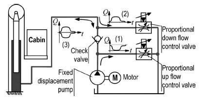
37 Shown is a configuration with five cartridge valves. V5 could be replaced with a pressure-relief valve. The flow from the pump to each chamber and the flow from each chamber to the tank are controlled by four separate valves. A fifth valve connects the pump directly to the tank. This configuration can emulate many spool valve geometries simply by changing the control software. K. Craig 37
38 Much study of independent metering valves focuses on the ability of the configuration to operate as a variable geometry spool valve, i.e., it is able to recreate the flow characteristics associated with different geometries. Changes made in software allow the valve s characteristics to be significantly altered, giving rise to names such as smart valve, multi-function valve, and programmable valve. From an efficiency standpoint, the more important property of independent metering valves is the ability to independently control the flows into and out of both cylinder chambers. The practical significance of this is independent control of the cylinder pressures. K. Craig 38
39 When such a configuration is used with a loadsensing pump, there is potential for energy savings. Since the pressures can be independently specified, a given net force on the cylinder can be achieved in a variety of ways. By setting one chamber pressure to a low level, the other chamber pressure can be used to achieve the required load force with as low a pressure as possible. The result is a lower maximum chamber pressure. For a load-sensing pump, the supply pressure (and thus the input energy) will be significantly reduced. K. Craig 39
40 Regeneration Flow If a constant pressure source is used, then no matter how the system pressures change, the energy supplied for two different situations will be equal if the flows are equal. The only way to save energy is to reduce the flow from the pump. This may be accomplished by recycling hydraulic fluid already delivered to the system. Regeneration is the process of directing flow from one chamber into the other without the use of the pump. K. Craig 40
41 Regeneration flow can be used whenever the cylinder chamber supplied by the pump actually has a lower pressure then the other chamber. This commonly occurs during deceleration periods or when large force is acting in the direction of motion, e.g., lowering a heavy load. This type of load is called an overrunning load. In the figure on the slide 34, flow could be regenerated from one chamber to the other through the return valves V3 and V4. This is referred to as low-side regeneration. This system has a check valve in the return line which supports a slight pressure drop before opening, thus maintaining positive pressure. The flow could be in either direction, depending on the direction of the overrunning load. Energy is saved because the required supply flow is reduced. K. Craig 41
42 A single-rod cylinder has a significant difference in the piston areas. When only a small positive load force is required (e.g., when extending the rod with nearly constant velocity), the pressure of the rod-end side can exceed the pressure of the head end. Thus, fluid can be regenerated from the rod chamber to the head chamber. This type of regeneration has been used with a four-valve configuration by allowing the flow to pass through the supply valves (fluid flows first through valve V2 and then valve V1 in the figure on slide 34.) In order for this to be possible, the rod chamber pressure must exceed the source pressure. K. Craig 42
43 This type of flow is called high-side regeneration. High-side regeneration can boost the maximum extension speed, but usually requires significantly higher source pressure (and hence greater energy consumption for a load-sensing pump) than normal operation. A 5-valve configuration which uses a valve to control flow directly between the cylinder ports has been shown to save energy. This is shown on the next slide. Valve #3 is the regeneration valve. The extra valve here connects the two cylinder ports directly and does not connect the pressure source and tank (although a relief valve is included which does provide this function.) K. Craig 43
44 Five-Valve Configuration with True Cross Port Flow K. Craig 44
45 When true cross port flow is possible, the restrictions on the pressures during regeneration are less restrictive. Thus, when an overrunning load is present, the pressure in the regeneration line can exceed the tank pressure significantly. Similarly for constant velocity extension, the rod chamber pressure need not exceed the supply pressure to use regeneration. The only restriction is that the cylinder chamber supplied by the pump actually has a lower pressure than the other chamber. The flow from the high pressure chamber can be used to either reduce the pump flow (thus saving energy) or increase the maximum possible flow (thus increasing the speed). K. Craig 45
46 Energy Recovery Accumulator In fluid power systems, an accumulator often acts as an energy storage device. A hydro-pneumatic accumulator contains a quantity of pre-charged gas (often nitrogen is used) and a port through which oil can enter or leave the accumulator. The gas is separated from the oil by a barrier such as a piston, bladder, or diaphragm. When the port is exposed to high pressure, oil enters the accumulator, compressing the gas and storing energy. When the port pressure falls, oil will flow from the accumulator under the force of the pressurized gas. K. Craig 46
47 Accumulators are able to integrate directly into hydraulic systems and have been used in many applications. An energy-recovery system for a hydraulic elevator has been proposed which incorporates a hydraulic accumulator and a four-quadrant motor. As the elevator traveled both upward and downward, oil was directed through the hydraulic motor. This enabled both capture and reutilization of the potential energy. A variable-frequency drive electric motor connected to the hydraulic motor allowed the hydraulic motor to supplement the energy provided to the load or to recover excess energy. (See next slide). K. Craig 47

48 K. Craig 48
49 An energy recovery system for a hydraulic crane has been developed (see slide 48). This system incorporates a pair of assistant cylinders mounted in a parallel force configuration with the main boom cylinder, thus sharing the load among all three cylinders. When the load is first raised, the assistant cylinders draw oil from the oil reservoir through a check valve. During this motion, all the force is provided by the main cylinder. When the cylinders retract while lowering the load, the force of the load forces oil from the assistant cylinders into an accumulator. The next time a load is lifted (and for all subsequent cycles) the pressure stored in the accumulator acts on the assistant cylinders. K. Craig 49
50 This significantly reduces the load required from the main cylinder, allowing the load-sensing pump to supply flow at a lower pressure to the main cylinder. This results in significant energy savings. This energy recovery system is essentially decoupled from the original system since there is no flow directly between the main cylinder and the assistant cylinders. The disadvantage of this type of system is the requirement for one or two additional hydraulic cylinders. K. Craig 50

51 K. Craig 51
52 A novel energy recovery system for hydraulic cylinders is shown on the next slide. The system consists of an accumulator and two control valves, through which the flows to and from the cylinder chambers are controlled. A regeneration flow path is created when both valves are opened. The effect of this modification is to decouple the regeneration flows, meaning the flow out of the high pressure cylinder need not equal the flow into the low pressure cylinder. This is the case for a simple regeneration path composed only of piping and valves, but when an accumulator is used, excess flow from one cylinder can be stored in the accumulator or extra flow may be supplied from the accumulator to the cylinder. K. Craig 52

53 Novel energy recovery system for hydraulic cylinders K. Craig 53
54 The accumulator may be charged whenever there is flow out of a cylinder with pressure higher than that of the accumulator, and flow from the accumulator can replace pump flow whenever there is flow into a cylinder chamber at a lower pressure than the accumulator. The accumulator reduces throttling losses by acting as a second flow source or sink. High-pressure flow out of a cylinder can be directed to the accumulator rather than simply throttled to the tank. The throttling loss is lower because of the lower pressure drop. The figure illustrates the situation where a flow Q from a cylinder at pressure p cyl is throttled to the reference pressure and the case when it flows into an accumulator with pressure p ac. K. Craig 54
55 The shaded areas in the diagram represent the amounts of energy lost due to throttling and recovered by the accumulator. It is noted that although energy is stored in the accumulator, it could only be reused immediately if another cylinder pressure is below the pressure p ac. Then, the accumulator could act as a secondary pressure source to supply flow to the cylinder at low pressure, replacing the flow from the pump. Of course, for a very slight pressure drop, the maximum achievable flow through a valve may be less than the required amount. In such cases, the accumulator can act as a source or sink in parallel with the main pressure source or the tank, which still provides a portion of the benefits seen when the accumulator is used to provide the entire flow. K. Craig 55
Test Which component has the highest Energy Density? A. Accumulator. B. Battery. C. Capacitor. D. Spring.
 Test 1 1. Which statement is True? A. Pneumatic systems are more suitable than hydraulic systems to drive powerful machines. B. Mechanical systems transfer energy for longer distances than hydraulic systems.
Design and Modeling of Fluid Power Systems ME 597/ABE 591
 Systems ME 597/ABE 591 Dr. Monika Ivantysynova MAHA Professor Flud Power Systems MAHA Fluid Power Research Center Purdue University Systems Dr. Monika Ivantysynova, Maha Professor Fluid Power Systems Mivantys@purdue.edu
Chapter 2. Background
 Chapter 2 Background The purpose of this chapter is to provide the necessary background for this research. This chapter will first discuss the tradeoffs associated with typical passive single-degreeof-freedom
Hydraulic energy control, conductive part
 Chapter 2 2 Hydraulic energy control, conductive part Chapter 2 Hydraulic energy control, conductive part To get the hydraulic energy generated by the hydraulic pump to the actuator, cylinder or hydraulic
FEASIBILITY STYDY OF CHAIN DRIVE IN WATER HYDRAULIC ROTARY JOINT
 FEASIBILITY STYDY OF CHAIN DRIVE IN WATER HYDRAULIC ROTARY JOINT Antti MAKELA, Jouni MATTILA, Mikko SIUKO, Matti VILENIUS Institute of Hydraulics and Automation, Tampere University of Technology P.O.Box
TUTORIAL QUESTIONS FOR THE INDUSTRIAL HYDRAULICS COURSE TEP 4205
 TUTORIAL QUESTIONS FOR THE INDUSTRIAL HYDRAULICS COURSE TEP 4205 The book for the course is Principles of Hydraulic System Design, by Peter J Chapple. Published by Coxmoor Publishing Co., UK. Available
three different ways, so it is important to be aware of how flow is to be specified
 Flow-control valves Flow-control valves include simple s to sophisticated closed-loop electrohydraulic valves that automatically adjust to variations in pressure and temperature. The purpose of flow control
TUTORIAL QUESTIONS FOR COURSE TEP 4195
 TUTORIL QUESTIONS FOR COURSE TEP 4195 Data: Hydraulic Oil Density 870 kg/m 3 bsolute viscosity 0.03 Ns/m 2 Spool valve discharge coefficient 0.62. 1) hydrostatic transmission has a variable displacement
White paper: Originally published in ISA InTech Magazine Page 1
 Page 1 Improving Differential Pressure Diaphragm Seal System Performance and Installed Cost Tuned-Systems ; Deliver the Best Practice Diaphragm Seal Installation To Compensate Errors Caused by Temperature
SOFT SWITCHING APPROACH TO REDUCING TRANSITION LOSSES IN AN ON/OFF HYDRAULIC VALVE
 SOFT SWITCHING APPROACH TO REDUCING TRANSITION LOSSES IN AN ON/OFF HYDRAULIC VALVE Michael B. Rannow Center for Compact and Efficient Fluid Power Department of Mechanical Engineering University of Minnesota
CLOSED CIRCUIT HYDROSTATIC TRANSMISSION
 Energy conservation and other advantages in Mobile Equipment Through CLOSED CIRCUIT HYDROSTATIC TRANSMISSION C. Ramakantha Murthy Technical Consultant Various features/advantages of HST Hydrostatic transmissions
A pump is a machine used to move liquid through a piping system and to raise the pressure of the liquid.
 What is a pump A pump is a machine used to move liquid through a piping system and to raise the pressure of the liquid. Why increase a liquid s pressure? Static elevation a liquid s pressure must be increased
ESCONDIDO FIRE DEPT TRAINING MANUAL Section DRIVER OPERATOR Page 1 of 13 Pumps and Accessory Equipment Revised
 DRIVER OPERATOR Page 1 of 13 PUMPS AND ACCESSORY EQUIPMENT Pumps are designed for many different purposes. In order to understand the proper application and operation of a pump in a given situation, firefighters
Input, Control and Processing elements
 PNEUMATIC & HYDRAULIC SYSTEMS CHAPTER FIVE Input, Control and Processing elements Dr. Ibrahim Naimi Valves The function of valves is to control the fluid path or the pressure or the flow rate. Depending
Components of Hydronic Systems
 Valve and Actuator Manual 977 Hydronic System Basics Section Engineering Bulletin H111 Issue Date 0789 Components of Hydronic Systems The performance of a hydronic system depends upon many factors. Because
Pneumatic & Hydraulic SYSTEMS
 Pneumatic & Hydraulic SYSTEMS CHAPTER EIGHT HYDRAULIC PUMPS AND ACTUATORS Dr. Ibrahim Naimi The higher the discharge pressure, the lower the volumetric efficiency because internal leakage
Lecture 6. Systems review exercise To be posted this afternoon Due in class (10/23/15)
") 153 Systems review exercise To be posted this afternoon Due in class (10/23/15) Lecture 6 Coming week: Lab 13: Hydraulic Power Steering Lab 14: Integrated Lab (Hydraulic test bench) Topics today: 2 min
153 Systems review exercise To be posted this afternoon Due in class (10/23/15) Lecture 6 Coming week: Lab 13: Hydraulic Power Steering Lab 14: Integrated Lab (Hydraulic test bench) Topics today: 2 min
Step Motor. Mechatronics Device Report Yisheng Zhang 04/02/03. What Is A Step Motor?
 Step Motor What is a Step Motor? How Do They Work? Basic Types: Variable Reluctance, Permanent Magnet, Hybrid Where Are They Used? How Are They Controlled? How To Select A Step Motor and Driver Types of
Application Note Original Instructions Development of Gas Fuel Control Systems for Dry Low NOx (DLN) Aero-Derivative Gas Turbines
 Aero-Derivative Gas Turbines") Application Note 83404 Original Instructions Development of Gas Fuel Control Systems for Dry Low NOx (DLN) Aero-Derivative Gas Turbines Woodward reserves the right to update any portion of this publication
Application Note 83404 Original Instructions Development of Gas Fuel Control Systems for Dry Low NOx (DLN) Aero-Derivative Gas Turbines Woodward reserves the right to update any portion of this publication
Exercise 4-1. Flowmeters EXERCISE OBJECTIVE DISCUSSION OUTLINE DISCUSSION. Rotameters. How do rotameter tubes work?
 Exercise 4-1 Flowmeters EXERCISE OBJECTIVE Learn the basics of differential pressure flowmeters via the use of a Venturi tube and learn how to safely connect (and disconnect) a differential pressure flowmeter
INDIAN INSTITUTE OF TECHNOLOGY KHARAGPUR NPTEL ONLINE CERTIFICATION COURSE. On Industrial Automation and Control
 INDIAN INSTITUTE OF TECHNOLOGY KHARAGPUR NPTEL ONLINE CERTIFICATION COURSE On Industrial Automation and Control By Prof. S. Mukhopadhyay Department of Electrical Engineering IIT Kharagpur Topic Lecture
Chapter 13: Application of Proportional Flow Control
 Chapter 13: Application of Proportional Flow Control Objectives The objectives for this chapter are as follows: Review the benefits of compensation. Learn about the cost to add compensation to a hydraulic
Lecture 7. Lab 14: Integrative lab (part 2) Lab 15: Intro. Electro-hydraulic Control Setups (2 sessions)
 Lab 15: Intro. Electro-hydraulic Control Setups (2 sessions)") Coming week s lab: Lecture 7 Lab 14: Integrative lab (part 2) Lab 15: Intro. Electro-hydraulic Control Setups (2 sessions) 4 th floor Shepherd (room # TBD) Guest lecturer next week (10/30/15): Dr. Denis
Coming week s lab: Lecture 7 Lab 14: Integrative lab (part 2) Lab 15: Intro. Electro-hydraulic Control Setups (2 sessions) 4 th floor Shepherd (room # TBD) Guest lecturer next week (10/30/15): Dr. Denis
2/4/6.3, PAH 10/12.5, PAH 50/63/70/80/100 pumps
 Data sheet PAH pumps 2/4/6.3, PAH 10/12.5, PAH 2/4/6.3, PAH 10/12.5, PAH 20/25/32 and and PAH 50/63/70/80/100 PAH 50/63/70/80/100 pumps danfoss.high-pressurepumps.com hpp.danfoss.com Table of Contents
Understanding the benefits of using a digital valve controller. Mark Buzzell Business Manager, Metso Flow Control
 Understanding the benefits of using a digital valve controller Mark Buzzell Business Manager, Metso Flow Control Evolution of Valve Positioners Digital (Next Generation) Digital (First Generation) Analog
A STUDY OF HYDRAULIC RESISTANCE OF VISCOUS BYPASS GAP IN MAGNETORHEOLOGICAL DAMPER
 ACTA UNIVERSITATIS AGRICULTURAE ET SILVICULTURAE MENDELIANAE BRUNENSIS Volume 64 134 Number 4, 2016 http://dx.doi.org/10.11118/actaun201664041199 A STUDY OF HYDRAULIC RESISTANCE OF VISCOUS BYPASS GAP IN
FLOW RATE STATIC BALANCING Valves for radiators
 Balancing part 3 TECHNICAL FOCUS FLOW RATE STATIC BALANCING Valves for radiators The valves for radiators equipped with pre-setting device play a very important role in balancing the heating systems circuits.
LECTURE-23: Basic concept of Hydro-Static Transmission (HST) Systems
 Systems") MODULE-6 : HYDROSTATIC TRANSMISSION SYSTEMS LECTURE-23: Basic concept of Hydro-Static Transmission (HST) Systems 1. INTRODUCTION The need for large power transmissions in tight space and their control
MODULE-6 : HYDROSTATIC TRANSMISSION SYSTEMS LECTURE-23: Basic concept of Hydro-Static Transmission (HST) Systems 1. INTRODUCTION The need for large power transmissions in tight space and their control
ECH 4224L Unit Operations Lab I Fluid Flow FLUID FLOW. Introduction. General Description
 FLUID FLOW Introduction Fluid flow is an important part of many processes, including transporting materials from one point to another, mixing of materials, and chemical reactions. In this experiment, you
Appendix A: Motion Control Theory
 Appendix A: Motion Control Theory Objectives The objectives for this appendix are as follows: Learn about valve step response. Show examples and terminology related to valve and system damping. Gain an
Lecture 6. Systems review exercise To be posted this weekend Due next Friday (3/6)
") 150 Systems review exercise To be posted this weekend Due next Friday (3/6) Lecture 6 Coming week: Lab 13: Hydraulic Power Steering Lab 14: Integrated Lab (Hydraulic test bench) Topics today: Pumps and
150 Systems review exercise To be posted this weekend Due next Friday (3/6) Lecture 6 Coming week: Lab 13: Hydraulic Power Steering Lab 14: Integrated Lab (Hydraulic test bench) Topics today: Pumps and
ENERGY RECOVERY SYSTEM FROM THE VEHICLE DAMPERS AND THE INFLUENCE OF THE TANK PRESSURE
 The 3rd International Conference on Computational Mechanics and Virtual Engineering COMEC 2009 29 30 OCTOBER 2009, Brasov, Romania ENERGY RECOVERY SYSTEM FROM THE VEHICLE DAMPERS AND THE INFLUENCE OF THE
Part C: Electronics Cooling Methods in Industry
 Part C: Electronics Cooling Methods in Industry Indicative Contents Heat Sinks Heat Pipes Heat Pipes in Electronics Cooling (1) Heat Pipes in Electronics Cooling (2) Thermoelectric Cooling Immersion Cooling
The filling pressure of SUSPA gas springs depends on the extension force and the geometry and is between 10 and 230 bar.
 FAQ s 1. Why is there a warning on the gas spring? Gas springs are filled with compressed nitrogen. The warning is intended to prevent unauthorized people from opening the gas spring or making other changes
Experiment No.3: Flow through orifice meter. Background and Theory
 Experiment No.3: Flow through orifice meter Background and Theory Flow meters are used in the industry to measure the volumetric flow rate of fluids. Differential pressure type flow meters (Head flow meters)
Seals Stretch Running Friction Friction Break-Out Friction. Build With The Best!
 squeeze, min. = 0.0035 with adverse tolerance build-up. If the O-ring is made in a compound that will shrink in the fluid, the minimum possible squeeze under adverse conditions then must be at least.076
V1000, A1000, E7, F7, G7,
 White Paper High Slip Braking Software Applicable, and P7 (V/f Motor Control Method) Mike Rucinski, Manager, Applications Engineering, Yaskawa Electric America, Inc. Paul Avery, Sr. Product Training Engineer,
Advancements in Compressor Anti-surge Control Valve Solutions
 Advancements in Compressor Anti-surge Control Valve Solutions As presented at: 59 th Annual Instrumentation Symposium for the Process Industries Texas A&M University College Station, Texas January 20-22,
IMECE DEVELOPMENT OF A HIGH-SPEED ON-OFF VALVE FOR SWITCH-MODE CONTROL OF HYDRAULIC CIRCUITS WITH FOUR-QUADRANT CONTROL
 Proceedings of the ASME 010 International Mechanical Engineering Congress & Exposition IMECE010 November 1-18, Vancouver, British Columbia IMECE010-37380 DEVELOPMENT OF A HIGH-SPEED ON-OFF VALVE FOR SWITCH-MODE
2. Hydraulic Valves, Actuators and Accessories. 24 Marks
 2. Hydraulic Valves, Actuators and Accessories 24 Marks Co related to chapter 602.2 Describe working principle of various components used in hydraulic & pneumatic systems. 602.3 Choose valves, actuators
ENERGY RECOVERY SYSTEM FOR EXCAVATORS WITH MOVABLE COUNTERWEIGHT
 Journal of KONES Powertrain and Transport, Vol. 2, No. 2 213 ENERGY RECOVERY SYSTEM FOR EXCAVATORS WITH MOVABLE COUNTERWEIGHT Artur Gawlik Cracow University of Technology Institute of Machine Design Jana
EFFECTIVE SOLUTIONS FOR SHOCK AND VIBRATION CONTROL
 EFFECTIVE SOLUTIONS FOR SHOCK AND VIBRATION CONTROL Part 1 Alan Klembczyk TAYLOR DEVICES, INC. North Tonawanda, NY Part 2 Herb LeKuch Shocktech / 901D Monsey, NY SAVIAC Tutorial 2009 Part 1 OUTLINE Introduction
PAHT pumps / PAHT G pumps / ATEX PAHT G pump
 Lenntech info@lenntech.com Tel. +31-152-610-900 www.lenntech.com Fax. +31-152-616-289 Data sheet PAHT 2-308 pumps / PAHT G 2-308 pumps / ATEX PAHT G pump danfoss.high-pressurepumps.com Table of Contents
So how does a turbocharger get more air into the engine? Let us first look at the schematic below:
 How a Turbo System Works Engine power is proportional to the amount of air and fuel that can get into the cylinders. All things being equal, larger engines flow more air and as such will produce more power.
VARIABLE DISPLACEMENT OIL PUMP IMPROVES TRACKED VEHICLE TRANSMISSION EFFICIENCY
 2018 NDIA GROUND VEHICLE SYSTEMS ENGINEERING AND TECHNOLOGY SYMPOSIUM POWER & MOBILITY (P&M) TECHNICAL SESSION AUGUST 7-9, 2018 NOVI, MICHIGAN VARIABLE DISPLACEMENT OIL PUMP IMPROVES TRACKED VEHICLE TRANSMISSION
11/12/2017 Erwin H. Doorenspleet
 Slide 1 Slide 2 Slide 3 Introduction: Density Measurement Additionally to mass flow multi-variable Coriolis mass flow meters also determine temperature and density Precise density measurement performance
FLUID POWER FLUID POWER EQUIPMENT TUTORIAL HYDRAULIC AND PNEUMATIC MOTORS. This work covers part of outcome 2 of the Edexcel standard module:
 FLUID POWER FLUID POWER EQUIPMENT TUTORIAL HYDRAULIC AND PNEUMATIC MOTORS This work covers part of outcome 2 of the Edexcel standard module: UNIT 21746P APPLIED PNEUMATICS AND HYDRAULICS The material needed
CH.4 Basic Components of Hydraulic and Pneumatic System/16 M HAP/17522/AE5G
 Content : 4.1 Hydraulic and Pneumatic actuators. 10 Marks Hydraulic Actuators - Hydraulic cylinders (single, double acting and telescopic) construction and working, Hydraulic motors (gear and piston type)
Module 5: Valves. CDX Diesel Hydraulics. Terms and Definitions. Categories of Valves. Types of Pressure Control Valves
 Terms and Definitions Categories of Valves Types of Pressure Control Valves Types and Operation of Pressure Relief Valves Operation of an Unloading Valve Operation of a Sequencing Valve Operation of a
The Performance Optimization of Rolling Piston Compressors Based on CFD Simulation
 Purdue University Purdue e-pubs International Compressor Engineering Conference School of Mechanical Engineering 2004 The Performance Optimization of Rolling Piston Compressors Based on CFD Simulation
Introduction to hmtechnology
 Introduction to hmtechnology Today's motion applications are requiring more precise control of both speed and position. The requirement for more complex move profiles is leading to a change from pneumatic
Silencers. Transmission and Insertion Loss
 Silencers Practical silencers are complex devices, which operate reducing pressure oscillations before they reach the atmosphere, producing the minimum possible loss of engine performance. However they
LogSplitterPlans.Com
 Hydraulic Pump Basics LogSplitterPlans.Com Hydraulic Pump Purpose : Provide the Flow needed to transmit power from a prime mover to a hydraulic actuator. Hydraulic Pump Basics Types of Hydraulic Pumps
Definitions of Technical Terms
 Definitions of Technical Terms ABSOLUTE A measure having as it s zero point of base the complete absence of the entity being measured. ABSOLUTE PRESSURE A pressure scale with zero point at a perfect vacuum.
Turbo Tech 101 ( Basic )
") Turbo Tech 101 ( Basic ) How a Turbo System Works Engine power is proportional to the amount of air and fuel that can get into the cylinders. All things being equal, larger engines flow more air and as
Turbo Tech 101 ( Basic ) How a Turbo System Works Engine power is proportional to the amount of air and fuel that can get into the cylinders. All things being equal, larger engines flow more air and as
Soft Switching Approach to Reducing Transition Losses in an On/Off Hydraulic Valve
 Soft Switching Approach to Reducing Transition Losses in an On/Off Hydraulic Valve Michael B. Rannow e-mail: rann0018@umn.edu Perry Y. Li 1 e-mail: pli@me.umn.edu Center for Compact and Efficient Fluid
Adams-EDEM Co-simulation for Predicting Military Vehicle Mobility on Soft Soil
 Adams-EDEM Co-simulation for Predicting Military Vehicle Mobility on Soft Soil By Brian Edwards, Vehicle Dynamics Group, Pratt and Miller Engineering, USA 22 Engineering Reality Magazine Multibody Dynamics
White Paper: The Physics of Braking Systems
 White Paper: The Physics of Braking Systems The Conservation of Energy The braking system exists to convert the energy of a vehicle in motion into thermal energy, more commonly referred to as heat. From
EMaSM. Principles Of Sensors & transducers
 EMaSM Principles Of Sensors & transducers Introduction: At the heart of measurement of common physical parameters such as force and pressure are sensors and transducers. These devices respond to the parameters
FLUID FLOW. Introduction
 FLUID FLOW Introduction Fluid flow is an important part of many processes, including transporting materials from one point to another, mixing of materials, and chemical reactions. In this experiment, you
TECHNICAL PAPER 1002 FT. WORTH, TEXAS REPORT X ORDER
 I. REFERENCE: 1 30 [1] Snow Engineering Co. Drawing 80504 Sheet 21, Hydraulic Schematic [2] Snow Engineering Co. Drawing 60445, Sheet 21 Control Logic Flow Chart [3] Snow Engineering Co. Drawing 80577,
Lecture 4. Lab 8 Check valve and pilot-operated check valves Lab 9 Flow divider. Update: Identifying lab objectives Review: Metering/Bleed-off
 98 Lecture 4 Labs coming week: Lab 8 Check valve and pilot-operated check valves Lab 9 Flow divider Update: Identifying lab objectives Review: Metering/Bleed-off (More) efficient circuits? Check and Pilot-to-Open-Check
FRONTAL OFF SET COLLISION
 FRONTAL OFF SET COLLISION MARC1 SOLUTIONS Rudy Limpert Short Paper PCB2 2014 www.pcbrakeinc.com 1 1.0. Introduction A crash-test-on- paper is an analysis using the forward method where impact conditions
LEAD SCREWS 101 A BASIC GUIDE TO IMPLEMENTING A LEAD SCREW ASSEMBLY FOR ANY DESIGN
 LEAD SCREWS 101 A BASIC GUIDE TO IMPLEMENTING A LEAD SCREW ASSEMBLY FOR ANY DESIGN Released by: Keith Knight Kerk Products Division Haydon Kerk Motion Solutions Lead Screws 101: A Basic Guide to Implementing
Mohit Law. Keywords: Machine tools, Active vibration isolation, Electro-hydraulic actuator, Design guidelines, Sensitivity analysis
 College of Engineering., Pune, Maharashtra, INDIA. Design Guidelines for an Electro-Hydraulic Actuator to Isolate Machines from Vibrations Mohit Law Department of Mechanical Engineering Indian Institute
Constructive Influences of the Energy Recovery System in the Vehicle Dampers
 Constructive Influences of the Energy Recovery System in the Vehicle Dampers Vlad Serbanescu, Horia Abaitancei, Gheorghe-Alexandru Radu, Sebastian Radu Transilvania University Brasov B-dul Eroilor nr.
China. Keywords: Electronically controled Braking System, Proportional Relay Valve, Simulation, HIL Test
 Applied Mechanics and Materials Online: 2013-10-11 ISSN: 1662-7482, Vol. 437, pp 418-422 doi:10.4028/www.scientific.net/amm.437.418 2013 Trans Tech Publications, Switzerland Simulation and HIL Test for
Gas exchange process for IC-engines: poppet valves, valve timing and variable valve actuation
 Gas exchange process for IC-engines: poppet valves, valve timing and variable valve actuation Topics Analysis of the main parameters influencing the volumetric efficiency in IC engines: - Valves and valve
HYBRID LINEAR ACTUATORS BASICS
 HYBRID LINEAR ACTUATORS BASICS TECHNICAL OVERVIEW Converting the rotary motion of a stepping motor into linear motion can be accomplished by several mechanical means, including rack and pinion, belts and
STEAM the hydraulic hybrid system for excavators
 Pagina1 STEAM the hydraulic hybrid system for excavators Abstract During the past four years the Institute for Fluid Power Drives and Controls in Aachen has developed a hydraulic hybrid architecture for
Fig Electromagnetic Actuator
 This type of active suspension uses linear electromagnetic motors attached to each wheel. It provides extremely fast response, and allows regeneration of power consumed by utilizing the motors as generators.
Comparison between Fluid Viscous Dampers and Friction Damper Devices. Fluid Viscous Dampers (FVD) Friction Damper Device (FDD) Working principle:
 Friction Damper Device (FDD) Working principle:") Fluid Viscous Dampers (FVD) Working principle: FVD is a central piston strokes through a fluid-filled chamber. As the piston moves it pushes fluid through orifices around and through the piston head. Fluid
Fluid Viscous Dampers (FVD) Working principle: FVD is a central piston strokes through a fluid-filled chamber. As the piston moves it pushes fluid through orifices around and through the piston head. Fluid
Motional emf. as long as the velocity, field, and length are mutually perpendicular.
 Motional emf Motional emf is the voltage induced across a conductor moving through a magnetic field. If a metal rod of length L moves at velocity v through a magnetic field B, the motional emf is: ε =
Internal Combustion Engines
 Internal Combustion Engines The internal combustion engine is an engine in which the burning of a fuel occurs in a confined space called a combustion chamber. This exothermic reaction of a fuel with an
SMART FLUID SELF ADAPTIVE DAMPER SYSTEM (SFSADS)
") SMART FLUID SELF ADAPTIVE DAMPER SYSTEM (SFSADS) Santhosh Sivan. K 1, Chandrasekar Sundaram 2 and Hari Krishnan. R 3 ABSTRACT 1,2 Department of Automobile Engineering, Anna University, MIT, Chennai, India
SMART FLUID SELF ADAPTIVE DAMPER SYSTEM (SFSADS) Santhosh Sivan. K 1, Chandrasekar Sundaram 2 and Hari Krishnan. R 3 ABSTRACT 1,2 Department of Automobile Engineering, Anna University, MIT, Chennai, India
FLUID POWER TUTORIAL HYDRAULIC PUMPS APPLIED PNEUMATICS AND HYDRAULICS H1
 FLUID POWER TUTORIAL HYDRAULIC PUMPS This work covers outcome 2 of the Edexcel standard module: APPLIED PNEUMATICS AND HYDRAULICS H1 The material needed for outcome 2 is very extensive so the tutorial
AN INVESTIGATION OF HYDRAULIC ACTUATOR PERFORMANCE TRADE-OFFS USING A GENERIC MODEL
 AN INVESTIGATION OF HYDRAULIC ACTUATOR PERFORMANCE TRADE-OFFS USING A GENERIC MODEL D. L. Wells, E. K. Iversen, C. C. Davis, S. C. Jacobsen Center for Engineering Design University of Utah Salt Lake City,
VB VALVES & AUTOMATION
 Introduction to Valve What are Valves? Valves are mechanical device that controls the flow and pressure within a system or process. They are essential components of a piping system that conveys liquids,
Hydraulic drives market trends and offerings
 White Paper Hydraulic drives market trends and offerings S.Krishnakumar Industrial Drives - Hydraulics Eaton India Engineering Center Pune, India Keywords: Hydraulic Drives; Motors; Radial Piston Motor;
Cane Creek Double Barrel Instructions
 Cane Creek Double Barrel Instructions Congratulations on your purchase of the Cane Creek Double Barrel rear shock. Developed in partnership with Öhlins Racing, the Double Barrel brings revolutionary suspension
USING STANDARD ISOLATORS TO CONTROL UNWANTED MACHINE VIBRATION
 USING STANDARD ISOLATORS TO CONTROL UNWANTED MACHINE VIBRATION From small medical pumps to large diesel engines, vibration is unavoidable and dangerous if left unchecked in rotating and oscillating machinery.
CHAPTER 4: EXPERIMENTAL WORK 4-1
 CHAPTER 4: EXPERIMENTAL WORK 4-1 EXPERIMENTAL WORK 4.1 Preamble 4-2 4.2 Test setup 4-2 4.2.1 Experimental setup 4-2 4.2.2 Instrumentation, control and data acquisition 4-4 4.3 Hydro-pneumatic spring characterisation
LIQUID MEASUREMENT STATION DESIGN Class No
 LIQUID MEASUREMENT STATION DESIGN Class No. 2230.1 Michael Frey Systems Sales Manager Daniel Measurement & Control, Inc. 5650 Brittmoore Rd. Houston, Texas 77041 INTRODUCTION The industry continues to
TORQUE-MOTORS. as Actuators in Intake and Exhaust System. SONCEBOZ Rue Rosselet-Challandes 5 CH-2605 Sonceboz.
 TORQUE-MOTORS as Actuators in Intake and Exhaust System SONCEBOZ Rue Rosselet-Challandes 5 CH-2605 Sonceboz Tel.: +41 / 32-488 11 11 Fax: +41 / 32-488 11 00 info@sonceboz.com www.sonceboz.com as Actuators
Transmission Error in Screw Compressor Rotors
 Purdue University Purdue e-pubs International Compressor Engineering Conference School of Mechanical Engineering 2008 Transmission Error in Screw Compressor Rotors Jack Sauls Trane Follow this and additional
Electromagnetic Fully Flexible Valve Actuator
 Electromagnetic Fully Flexible Valve Actuator A traditional cam drive train, shown in Figure 1, acts on the valve stems to open and close the valves. As the crankshaft drives the camshaft through gears
WEEK 4 Dynamics of Machinery
 WEEK 4 Dynamics of Machinery References Theory of Machines and Mechanisms, J.J.Uicker, G.R.Pennock ve J.E. Shigley, 2003 Prof.Dr.Hasan ÖZTÜRK 1 DYNAMICS OF RECIPROCATING ENGINES Prof.Dr.Hasan ÖZTÜRK The
YASKAWA AC Drives. Compressor Applications Application Overview
 YASKAWA AC Drives Compressor Applications Application Overview This document provides a general application overview and is intended to familiarize the reader with the benefits of using AC drives in compressor
The Mechanics of Tractor Implement Performance
 The Mechanics of Tractor Implement Performance Theory and Worked Examples R.H. Macmillan CHAPTER 2 TRACTOR MECHANICS Printed from: http://www.eprints.unimelb.edu.au CONTENTS 2.1 INTRODUCTION 2.1 2.2 IDEAL
Modelling Automotive Hydraulic Systems using the Modelica ActuationHydraulics Library
 Modelling Automotive Hydraulic Systems using the Modelica ActuationHydraulics Library Peter Harman Ricardo UK Ltd. Leamington Spa, UK Peter.Harman@ricardo.com Abstract This paper describes applications
Modeling and improving of an Hydraulic Test Bench for car seats
 Modeling and improving of an Hydraulic Test Bench for car seats D.J.W. Belleter - 63931 CST 21.49 Bachelor End Project Project supervisor: dr. Ir. W.J.A.E.M. Post Eindhoven University of technology Department
ACTIVE AXIAL ELECTROMAGNETIC DAMPER
 ACTIVE AXIAL ELECTROMAGNETIC DAMPER Alexei V. Filatov, Larry A. Hawkins Calnetix Inc., Cerritos, CA, 973, USA afilatov@calnetix.com Venky Krishnan, Bryan Lam Direct Drive Systems Inc., Cerritos, CA, 973,
A Practical Guide to Free Energy Devices
 A Practical Guide to Free Energy Devices Part PatD20: Last updated: 26th September 2006 Author: Patrick J. Kelly This patent covers a device which is claimed to have a greater output power than the input
Content. Chapter 1 Hydraulic energy converters... 10
 Content Chapter 1 Hydraulic energy converters... 10 1.1 List of symbols... 13 1.2 Hydraulic pump types, constant output... 14 1.2.1 External gear pumps... 16 1.2.2 Internal gear pumps... 17 1.2.3 Vane
Electromagnetic Induction, Faraday s Experiment
 Electromagnetic Induction, Faraday s Experiment A current can be produced by a changing magnetic field. First shown in an experiment by Michael Faraday A primary coil is connected to a battery. A secondary
Electronic Load-Sensing for Tractors
 Electronic Load-Sensing for Tractors Ulrich Lenzgeiger, Uwe Maier and Peter Schmuttermair Bosch Rexroth AG, Systems Engineering, Glockeraustr. 2, 89275 Elchingen, Germany E-Mail: ulrich.lenzgeiger@boschrexroth.de,
Testing Of Fluid Viscous Damper
 Testing Of Fluid Viscous Damper Feng Qian & Sunwei Ding, Jingjing Song Shanghai Research Institute of Materials, China Dr. Chien-Chih Chen US.VF Corp, Omni Device, China SUMMARY: The Fluid Viscous Damper
Describe the function of a hydraulic power unit
 Chapter 7 Source of Hydraulic Power Power Units and Pumps 1 Objectives Describe the function of a hydraulic power unit and identify its primary components. Explain the purpose of a pump in a hydraulic
Fluid Power Systems & Control
 Fluid Power Systems & Control K. Craig 1 Fluid Power Fluid Properties Fluid Mechanics Fundamentals Systems Dynamic System Modeling & Analysis Fundamentals Hydraulic Components: Valves, Pumps, Actuators
QuickStick Repeatability Analysis
 QuickStick Repeatability Analysis Purpose This application note presents the variables that can affect the repeatability of positioning using a QuickStick system. Introduction Repeatability and accuracy