didactecsanderson Mechanical & Automotive mechanisms MAM Mechanical Engineering Laboratory Apparatus Mechanical Engineering Laboratory Apparatus
|
|
|
- Lindsay Horton
- 5 years ago
- Views:
Transcription


1 2-YRWARRANTYONALLARMFIELDPRODUCTS DISCOVER WITH didactec Sanderson Mechanical Engineering Laboratory Apparatus Mechanical & Automotive mechanisms MAM Mechanical Mechanisms Automotive Mechanisms Theory of Machines NEW Part of The Armfield Didactec-Sanderson Range of Engineering Teaching Equipment The Didactec - Sanderson, range of engineering teaching equipment is renowned for excellent quality of build, ease of use and set-up for staff and student. The Armfield ADS or Armfield Didactec Sanderson range as it is now known has provided the fundamentals for Mechanical and Civil Engineering students the world over. The products are available over two distinct series, The MAM series (this data sheet), and the complementary SV Series. didactecsanderson Mechanical Engineering Laboratory Apparatus TOPICS COVERED by the ADS - MAM Series Topics covered by this Mechanical & Automotive Mechanisms (MAM) data sheet: Mechanical Mechanisms Automotive Mechanisms Theory of Machines TOPICS COVERED by the Complementary ADS - SV Series Topics covered by the complementary Statics & Vibrations (SV) data sheet: Statics Structures Vibration Balancing Materials Testing enviro PRODUCTS <EXTENDED> WARRANTY 2 years Provisonal

2 Universal Bench Mounted Frame SD1:10 The Armfield Didactec Sanderson Universal Bench Mounted Frame provides a very sensible alternative to to wall mounting, particularly since many new buildings are predominantly glass, with very flimsy dividing walls. The frame is designed to accommodate two items of ADS apparatus, allowing adequate space for students to work on each piece of equipment simultaneously. However it is possible to mount three pieces, in the case of the simple transmission system. By mounting the apparatus on the frame, experiments can be transported between rooms to any convenient location. Height: 0.7m Width: 1.2m Depth: 0.5m Net Weight: 28 kg Volume 0.62 m 3 Gross weight 32 kg
 and trailing (Secondary) shoe braking systems and the effect on the braking systems and the effect on")
3 Drum Brake Apparatus SD1:12 This apparatus has been developed specifically for Motor Vehicle Mechanics and Motor Vehicle Technicians Courses. It provides a means of demonstrating the difference in braking torque between leading (Primary) and trailing (Secondary) shoe braking systems and the effect on the braking systems and the effect on the braking torque of the various combinations of leading and trailing shoes. When the two shoes are linked together, the self energising action can be demonstrated. The apparatus is suitable for use in the laboratory and may be used by the Students to carry out simple experiments to investigate the relationship between actuating forces and the braking torques and for the determination of the co-efficient of friction between the brake lining and the drum. Two shoes with short brake linings are provided, additional shoes with full linings (SD1:12a) are available should these be required. For more advanced work, a special shoe may be supplied, fitted with an adjustable lining, (SD1:12b) this enables the Student to investigate the effect on the braking torque when the pressure point on the brake shoe is displaced relative to the pivot point. The apparatus is self contained and may be wall mounted or fitted to the Universal Bench Mounted Frame, Ref SD1:10. Height: 0.54m Width: 0.48m Depth: 0.27m Net Weight: 22 kg Shipping Specification Volume 0.14 m 3 Gross weight 26 kg

4 Gearbox Apparatus SD1:15 Most road vehicles are fitted with variable ratio gearboxes as a means of obtaining the best power application under the varying road conditions. Fundamentally the gearbox consists of gear wheels of different sizes which may be engaged as required. The sliding mesh box, although it is still used on heavy commercial vehicles, is seldom found on modern cars, but its basic construction and operation are important from the Student's point of view as it represents the basic layout from which most modern gearboxes have been developed. The Sanderson gearbox has been designed to represent a typical arrangement of a simple three forward ratio and reverse sliding mesh box. The unit may be used for classroom demonstrations and by Students in the laboratory. Pulleys fitted with protractors are attached to the input and output shafts so that the Student may determine and verify velocity and torque ratios. The Gearbox can be coupled to the Overdrive (Ref SD1:17) and Differential (Ref SD1:16) to represent a simple transmission system. The unit may be wall mounted or fitted to the Universal Bench Mounted Frame, Ref SD1:10. Height: 0.54m Width: 0.48m Depth: 0.27m Net Weight: 14 kg Volume 0.14 m 3 Gross weight 18 kg

5 Rear Axle Drive & Differential Apparatus SD1:16a Height: 0.30m Width: 0.40m Depth: 0.38m Net Weight: 16 kg Volume 0.1 m 3 Gross weight 20 kg Crown Wheel & Pinion Version SD1:16a Many students find it difficult to visualise the action of a differential when used as a means of providing a drive from the gearbox to each axle shaft while allowing independent motion between shafts. The Sanderson Differential Unit has been designed to demonstrate the action of:- Crown Wheel and pinion rear axle drive and differential elements. The teaching value of this unit is, however, not limited to it's use for demonstration purposes only, but may also be used for simple experimental work in the laboratory. A pulley fitted with a protractor is secured to the input shaft, the output bevels are grooved and may be loaded individually or by means of a differential pulley arrangement so that students can determine and verify velocity ratios and torque distribution. The Differential can be coupled to the Overdrive (Ref. SD1:17) and/or Gearbox (Ref. SD1:15) to represent a simple transmission system. The unit may be wall mounted or mounted on the Sanderson Universal Bench Mounting Frame (Ref SD1:10).

6 Overdrive Apparatus SD1:17 The Sanderson Overdrive Unit has been designed to demonstrate the action of the gear elements in simple epicyclic gear arrangements. The unit may also be used by students in the laboratory to carry out simple experiments on epicyclic gearing. The apparatus illustrated has been designed specifically for Motor Vehicle courses and represents an application of a simple epicyclic arrangement of the type used in a motor vehicle overdrive. Pulleys fitted with protractors are secured to the input and output shafts to enable the student to determine and verify velocity and torque ratios. The unit may be wall mounted or attached to a Sanderson Universal Bench Mounted Frame, Ref SD1:10. The apparatus is designed so that the overdrive can be coupled to the Gearbox (Ref SD1:15) and Differential (Ref SD1:16) to represent a simple transmission system. Height: 0.37m Width: 0.35m Depth: 0.38m Net Weight: 8 kg Volume 0.1 m 3 Gross weight 10 kg

7 Braking & Accelerating Forces Apparatus SD1:18 Under conditions of braking or acceleration of a road vehicle, a load transfer between front and rear wheels occurs. The problem of load transfer arises since the accelerating or braking force is not applied to the centre of gravity of the vehicle but to the point of contact of the wheels with the road. The Braking and Accelerating Forces Apparatus has been designed to demonstrate this load transfer and to enable the student to carry out simple experiments to investigate the relationship between the forces involved in vehicle braking and acceleration. The relationship between these forces on front wheel drive, rear wheel drive, and four wheel drive may also be demonstrated. A "Model" Vehicle is supported on a beam load cell. The model has simulated road wheels and is drilled to receive a pin which may be inserted in varying positions to represent the centre of gravity of the vehicle. Suitable weights, cords and pulleys are used to apply varying horizontal braking or acceleration and inertia forces to the vehicle. The apparatus is portable and may be used in either the classroom the laboratory. Height: 0.80m Width: 0.30m Depth: 0.70m Net Weight: 18 kg Volume 0.3 m 3 Gross weight 24 kg

. Height: 0.")
8 Belt Friction Apparatus SD1:20 The Sanderson Belt Friction Apparatus has been designed to allow students to carry out investigations to compare the driving torque for a given degree of overlap of a flat leather belt, a badly fitted 'V' belt and a correctly fitted 'V' belt. Tension is introduced into the belt by hanging a mass from the ring attached to the end. The slipping torque is determined by the addition of a suitable mass attached to a cord wrapped around the drum. The angle of overlap can be varied from 30 to 210 degrees in increments of 30 degrees. The pulley is balanced and mounted on bearings to reduce frictional losses to a minimum. The unit can be wall mounted or fitted to the Sanderson Universal Bench Mounting Frame (Ref SD1:10). Height: 0.33m Width: 0.20m Depth: 0.25m Net Weight: 7 kg Volume m 3 Gross weight 10 kg 1) Flat Leather Belt 2) 'V' belt in badly machined groove, to simulate a worn pulley or a wrong belt (belt bottoms in groove). 3) Belt in correctly machined groove.

9 Borg-Warner Automatic Transmission Simulator SD1:22 The simplicity of operation and the ease with which the student may understand the Mechanical Power Flow in the Borg-Warner 35 gearbox has made the Sanderson simulator extremely popular with lecturers and students alike, in Technical Colleges throughout the world. Pins, inserted in accordance with the chart in the Laboratory Manual, lock discs to simulate the action of the clutches and brake bands. Each of the three forward ratios and reverse may be selected as required simply by inserting the appropriate pins as specified in the chart, and the relative movements of the different components can be clearly seen and studied. When the student has become familiar with the Mechanical Power Flow, he may then proceed to use the unit for diagnostic purposes. By following the step by step procedure laid down in the laboratory Manual he is able to study the effect of a faulty clutch or brake band. Also included in the Laboratory Manual are the calculations for the gear ratios which are the same for simulator and the Borg-Warner Box. The unit may be wall mounted or fitted to the Sanderson Universal Mounting Frame (Ref SD1:10). Height: 0.60m Width: 0.25m Depth: 0.26m Net Weight: 15 kg Volume 0.09 m 3 Gross weight 19 kg

10 Static & Dynamic Balancing Apparatus SD1:23 The Sanderson Dynamic Balancing Apparatus may be used effectively in both the classroom and the laboratory for simple demonstrations and experiments in the dynamic balancing of rotating and reciprocating systems. The rotating system is essentially a shaft, mounted on bearings, supported in a rigid frame, and driven by a small variable speed motor attached to the frame. Four discs, to which masses may be attached, are rigidly secured to the shaft. Each disc is suitably drilled and the sets of holes are positioned so that various conditions of un-balance in a rotating system can be simulated and the normal methods used to determine the magnitude and position of the counter-balance masses. The unit is supported on springs attached to the main support frame so that the oscillations set up by any unbalanced forces may be observed. The centre section of the shaft is in the form of a crank. A sleeve, piston and connecting rod are provided and may be fitted to the unit so that single cylinder engine balance conditions can be simulated. Various sector plates of suitable mass can be attached to the two inner discs so that the student can observe the effect on the oscillations of various conditions of partial balance of the reciprocating masses. Height: 0.47m Width: 0.60m Depth: 0.44m Net Weight: 28 kg Volume 0.22 m 3 Gross weight 32 kg

11 Plate Clutch Apparatus SD1:24 The Sanderson Plate Clutch Apparatus has been designed specifically for Motor Vehicle Technician Courses. It provides a means of demonstrating the effect of the mean radius of the friction surfaces and the spring pressure on the torque transmitted by a plate clutch. The apparatus may be used effectively by the student in the laboratory to carry out simple experiments to investigate the relationship between the normal pressure applied to the friction surfaces, the mean radius of the friction rings and the torque at which slip occurs. Three sets of clutch rings varying mean radius are supplied and provision is made so that the student can observe the effect on the slipping torque when using more than one pair of friction surfaces. The apparatus may be wall mounted or fitted to the Sanderson Universal Bench Mounting Frame, Ref SD1:10. Height: 0.30m Width: 0.30m Depth: 0.28m Net Weight: 10 kg Volume 0.06 m 3 Gross weight 14 kg

12 Disc Brake Apparatus SD1:25 The Sanderson Disc Brake Apparatus has been designed specifically for Motor Vehicle Courses and may be used effectively for classroom demonstrations. It may also be used by the student in the laboratory to carry out simple experiments to investigate the relationship between the normal force acting on the brake pads and the braking torque. The brake pads are located on bell crank levers to which the load hangers may be attached. A special load beam is provided for use when carrying out experiments with two brake pads. The supporting shafts are suitably drilled and pins provided so that the bell crank levers may be located in a number of radial positions. By attaching suitable masses to a cord wrapped round the pulley on the disc shaft, the braking torque may be determined. This apparatus may be considered complementary to the Sanderson Drum Brake Apparatus (Ref: SD1:12) and may be wall mounted or fitted to the Sanderson Universal Bench Mounting Frame (Ref: SD1:10). Height: 0.34m Width: 0.34m Depth: 0.32m Net Weight: 12 kg Volume m 3 Gross weight 16 kg

13 Simple Hydraulic System SD1:27 The Sanderson Hydraulic System is a simple piece of apparatus designed specifically for Motor Vehicle and Mechanical Engineering Technician Courses. It is intended for use in either the classroom or laboratory and may be used for simple demonstrations to illustrate how liquid can be used to transmit a force. The apparatus may also be used by the student to carry out simple experiments to investigate the relationships between the force on the plungers, the cross section area of the plungers and the fluid pressure in the system. The system consists essentially of three accurately machined cylinders and plungers whose cross-section areas are in the ration 1, 2 and 6. The three cylinders and the pressure gauge are connected in parallel and "on/off" taps are included in the circuit so that any of the cylinder units may be isolated from the system. A clear Perspex oil reservoir is fitted to the "master" cylinder. Two special load hangers are provided. The unit may be wall mounted or fitted to the Sanderson Universal Bench Mounting Frame, Ref: SD1:10. Height: 0.68m Width: 0.38m Depth: 0.28m Net Weight: 11 kg Volume 0.14 m 3 Gross weight 14 kg
 The relationship between the turning moment on the crank shaft and the crank angle for a given force on the piston.")
14 Crank Mechanism SD1:28 The apparatus is intended to represent a simple engine mechanism and may be used by the students for simple experiments to investigate: 1) The relationship between the piston displacement and the crank angle for a given connecting rod/crank radius ratio. 2) The relationship between the turning moment on the crank shaft and the crank angle for a given force on the piston. The crank effort may be determined by attaching suitable masses to the beam balance arm. The piston is fitted with brass rollers running on guide bars and needle roller bearings are fitted in the connecting rod so that friction is reduced to a minimum. A protractor is attached to the crank which may be rotated on the beam balance arm and clamped in any predetermined angular position. A linear scale is attached to the piston guide so that the piston displacement can be measured. The unit may be wall mounted or fitted to the Sanderson Universal Bench Mounting Frame (Ref SD1:10) Height: 0.54m Width: 0.48m Depth: 0.27m Net Weight: 14 kg Volume 0.14 m 3 Gross weight 18 kg

15 Acceleration of geared systems SD4:15 The Sanderson Geared System consists essentially of three shafts, each mounted on ball races, supported in a suitable frame and connected by gearing. Provision is made to change the gear ratios of suitable sizes are provided. A flywheel is attached to one of the shafts, whilst discs having varying mass moments of inertia may be attached to the other two shafts. A torque drum is secured to each shaft and suitable masses, attached to a cord wound on to one of the drums, provide a means of applying a torque to the system. By allowing the mass attached to the drum to fall a predetermined distance and measuring the time taken, the acceleration of the system can be calculated. The apparatus may be wall mounted or fitted to the Sanderson Universal Bench Mounting Frame (Ref SD1:10). Height: 0.65m Width: 0.35m Depth: 0.30m Net Weight: 23 kg Volume 0.14 m 3 Gross weight 27 kg


16 Epicyclic Gear Units SD4:17 / SD4:18 Epicyclic Gear Unit-3 Speed SD4:18 The Sanderson Epicyclic Gear Units have been developed to enable students to carry out investigations concerning epicyclic gearing in simple and more advanced forms. A version of this apparatus is the Sanderson Coupled Epicyclic Unit Ref SD4:17 which uses two standard speed unit or a forward and reverse unit. Recently introduced, the Sanderson Three Speed Epicyclic Gearbox Ref SD4:18 provides two forward speeds and reverse. A bracket fitted with a spring balance which enables the student to measure the holding torque on each annulus can be supplied as an optional extra. Ref SD4:18a. Bearings are used extensively throughout these units to reduce frictional losses to a minimum. All epicyclic units can be wall mounted or fitted to the Sanderson Universal Bench Mounting Frame (Ref SD1:10). Height: 0.60m Width: 0.25m Depth: 0.26m Net Weight: 18 kg Volume 0.09 m 3 Gross weight 22 kg Epicyclic Gear Unit-2 Speed SD4:17

 Simple to operate 2) All moving parts of the mechanism clearly visible 3) Suitable scales")


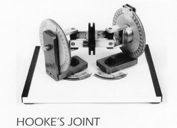
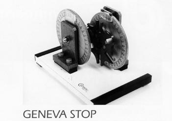
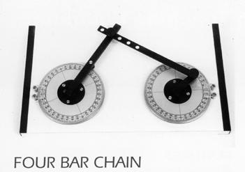
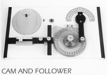
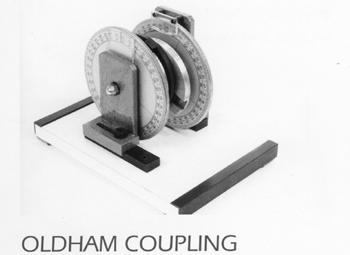
17 Mechanisms DT9 Series The DIDACTEC range of mechanisms has been designed to provide simple equipment for use as classroom demonstrations or for simple laboratory exercises. The range covers some of the more commonly used mechanisms employed in engineering applications. Features 1) Simple to operate 2) All moving parts of the mechanism clearly visible 3) Suitable scales provided 4) Light and portable Item Width Depth Height Net Weight Ref Slider Crank 0.31m 0.16m 0.06m 1.5 kg DT9.01 Scotch Yoke 0.31m 0.16m 0.05m 1.5 kg DT9.02 Slotted Link 0.31m 0.23m 0.06m 2.0kg DT9.03 Whitworth Quick Return 0.31m 0.16m 0.06m 1.5kg DT9.04 Four Bar Chain 0.39m 0.23m 0.06m 2.25 kg DT9.05 Geneva Stop 0.23m 0.16m 0.16m 2.5 kg DT9.06 Oldham Coupling 0.23m 0.16m 0.16m 2.5 kg DT9.07 Hooke's Joint 0.35m 0.23m 0.18m 4.0 kg DT9.08 Cam and Follower 0.39m 0.23m 0.07m 2.25 kg DT9.09
18

19 TS2-YRWARRANTYONALLARMFIELDPRODUC DISCOVER WITH The Didactec - Sanderson, range of engineering teaching equipment is renowned for excellent quality of build, ease of use and set-up for staff and student. The Armfield ADS or Armfield Didactec Sanderson range as it is now known has provided the fundamentals for Mechanical and Civil Engineering students the world over. The products are available over two distinct ranges, The MAM Series (this data sheet), and the complementary SV Series. Complementary Products: ADS - SV range Topics covered by the complementary Statics & Vibrations (SV) data sheet: Statics Structures Vibration Balancing Materials Testing <EXTENDED> WARRANTY 2 years Find us on YouTube! Follow us on Twitter, Facebook, LinkedIn and WordPress Head Office: Armfield Limited Bridge House, West Street, Ringwood, Hampshire. BH24 1DY England Telephone: Fax: sales@armfield.co.uk U.S. Office: Armfield Inc. 436 West Commodore Blvd (#2) Jackson, NJ Telephone: (732) Fax: (732) info@armfieldinc.com 2012 Armfield Ltd. All Rights Reserved We reserve the right to amend these specifications without prior notice. E&OE 0312/3k/SO2995 Scan QR code* to visit our website * Scan with smartphone with QR code scanning software installed. An ISO 9001 Company Innovators in Engineering Teaching Equipment learn more!
Department of Mechanical Engineering University of Engineering & Technology Lahore(KSK Campus).
.") Department of Mechanical Engineering University of Engineering & Technology Lahore(KSK Campus). LAB DATA Lab Incharge: Engr. Muhammad Amjad Lab Assistant: Abbas Ali Lay-Out of Mechanics of Machines Lab
Department of Mechanical Engineering University of Engineering & Technology Lahore(KSK Campus). LAB DATA Lab Incharge: Engr. Muhammad Amjad Lab Assistant: Abbas Ali Lay-Out of Mechanics of Machines Lab
Theory of Machines. CH-1: Fundamentals and type of Mechanisms
 CH-1: Fundamentals and type of Mechanisms 1. Define kinematic link and kinematic chain. 2. Enlist the types of constrained motion. Draw a label sketch of any one. 3. Define (1) Mechanism (2) Inversion
TYPICAL EXPERIMENTS Centers of gravity. Force triangle. Force polygon and Bow s Notation. Non- concurrent forces.
 MM 500-001 BASIC PANEL The panel is made from a perforated stainless steel sheet mounted on two supports with adjustable footings. The panel can be tilted, put in portrait or landscape position. Accessories
L15 Dynamics & Vibration Laboratory
 LABORATORY PLANNING GUIDE L15 Dynamics & Vibration Laboratory Content Covered subjects according to the curriculum... 2 Main concept... 3 Initial training provided for laboratory personnel... 3 Requirements
Moments. It doesn t fall because of the presence of a counter balance weight on the right-hand side. The boom is therefore balanced.
 Moments The crane in the image below looks unstable, as though it should topple over. There appears to be too much of the boom on the left-hand side of the tower. It doesn t fall because of the presence
Code No: R Set No. 1
 Code No: R05310304 Set No. 1 III B.Tech I Semester Regular Examinations, November 2007 KINEMATICS OF MACHINERY ( Common to Mechanical Engineering, Mechatronics, Production Engineering and Automobile Engineering)
STATIC AND DYNAMICS. Two Year Warranty
 FORCES HI-TECH Education is a market leader in the manufacture and provision of teaching equipment for Universities and Technical Colleges worldwide for both degree and vocational level. It has been designing
R10 Set No: 1 ''' ' '' '' '' Code No: R31033
 R10 Set No: 1 III B.Tech. I Semester Regular and Supplementary Examinations, December - 2013 DYNAMICS OF MACHINERY (Common to Mechanical Engineering and Automobile Engineering) Time: 3 Hours Max Marks:
Driver Driven. InputSpeed. Gears
 Gears Gears are toothed wheels designed to transmit rotary motion and power from one part of a mechanism to another. They are fitted to shafts with special devices called keys (or splines) that ensure
Hours / 100 Marks Seat No.
 17412 16117 3 Hours / 100 Seat No. Instructions (1) All Questions are Compulsory. (2) Answer each next main Question on a new page. (3) Illustrate your answers with neat sketches wherever necessary. (4)
DYNAMICS LABORATORY. AIM: To apply the knowledge gained in kinematics and dynamics of machines to real system.
 DYNAMICS LABORATORY AIM: To apply the knowledge gained in kinematics and dynamics of machines to real system. OBJECTIVES: To supplement the principles learnt in kinematics and Dynamics of Machinery. To
KINEMATICS OF MACHINARY UBMC302 QUESTION BANK UNIT-I BASICS OF MECHANISMS PART-A
 KINEMATICS OF MACHINARY UBMC302 QUESTION BANK UNIT-I BASICS OF MECHANISMS PART-A 1. Define the term Kinematic link. 2. Classify kinematic links. 3. What is Mechanism? 4. Define the terms Kinematic pair.
III B.Tech I Semester Supplementary Examinations, May/June
 Set No. 1 III B.Tech I Semester Supplementary Examinations, May/June - 2015 1 a) Derive the expression for Gyroscopic Couple? b) A disc with radius of gyration of 60mm and a mass of 4kg is mounted centrally
Theory of Machines II EngM323 Laboratory User's manual Version I
 Theory of Machines II EngM323 Laboratory User's manual Version I Table of Contents Experiment /Test No.(1)... 2 Experiment /Test No.(2)... 6 Experiment /Test No.(3)... 12 EngM323 Theory of Machines II
St.MARTIN S ENGINEERING COLLEGE Dhulapally, Secunderabad
 St.MARTIN S ENGINEERING COLLEGE Dhulapally, Secunderabad-500 014 Subject: Kinematics of Machines Class : MECH-II Group A (Short Answer Questions) UNIT-I 1 Define link, kinematic pair. 2 Define mechanism
2. a) What is pantograph? What are its uses? b) Prove that the peaucellier mechanism generates a straight-line motion. (5M+10M)
 What is pantograph? What are its uses? b) Prove that the peaucellier mechanism generates a straight-line motion. (5M+10M)") Code No: R22032 R10 SET - 1 1. a) Define the following terms? i) Link ii) Kinematic pair iii) Degrees of freedom b) What are the inversions of double slider crank chain? Describe any two with neat sketches.
Code No: R22032 R10 SET - 1 1. a) Define the following terms? i) Link ii) Kinematic pair iii) Degrees of freedom b) What are the inversions of double slider crank chain? Describe any two with neat sketches.
FRICTION DEVICES: DYNAMOMETER. Presented by: RONAK D. SONI Assistant Professor Parul Institute of Technology, Parul University
 FRICTION DEVICES: DYNAMOMETER Presented by: RONAK D. SONI Assistant Professor Parul Institute of Technology, Parul University DYNAMOMETER A dynamometer is a brake but in addition it has a device to measure
KINGS COLLEGE OF ENGINEERING DEPARTMENT OF MECHANICAL ENGINEERING
 KINGS COLLEGE OF ENGINEERING DEPARTMENT OF MECHANICAL ENGINEERING QUESTION BANK Sub Code/Name: ME 1352 DESIGN OF TRANSMISSION SYSTEMS Year/Sem: III / VI UNIT-I (Design of transmission systems for flexible
Universal Vibration Apparatus
 Universal Vibration Apparatus HVT12 Modular design means additional options can be acquired as and when budgets permit Uses non-contacting devices - LVDT and a proximity sensor to minimise unnecessary
TM1018. Geared Systems THEORY OF MACHINES. A set of products for dynamic and static experiments on geared and other drive systems
 Page 1 of 5 A set of products for dynamic and static experiments on geared and other drive systems Screenshot of the optional VDAS software For studies of velocity ratios and efficiencies of various geared
Geared Systems. theory of machines TM1018. A set of products for dynamic and static experiments on geared and other drive systems
 theory of machines TM1018 A set of products for dynamic and static experiments on geared and other drive systems Screenshot of the optional VDAS software For studies of velocity ratios and efficiencies
White Paper: The Physics of Braking Systems
 White Paper: The Physics of Braking Systems The Conservation of Energy The braking system exists to convert the energy of a vehicle in motion into thermal energy, more commonly referred to as heat. From
Mechanisms. Prepared by Juan Blázquez, Alissa Gildemann
 Unit 9 Mechanisms 1. Mechanisms Mechanisms are devices that transmit and convert forces and motions from an input to an output element. They enable us to use less effort to carry out a task. We can classify
ME6401 KINEMATICS OF MACHINERY UNIT- I (Basics of Mechanism)
") ME6401 KINEMATICS OF MACHINERY UNIT- I (Basics of Mechanism) 1) Define resistant body. 2) Define Link or Element 3) Differentiate Machine and Structure 4) Define Kinematic Pair. 5) Define Kinematic Chain.
ME6401 KINEMATICS OF MACHINERY UNIT- I (Basics of Mechanism) 1) Define resistant body. 2) Define Link or Element 3) Differentiate Machine and Structure 4) Define Kinematic Pair. 5) Define Kinematic Chain.
INDEX. PAGE Adjustment mechanism for radial position of block on rotating
 INDEX Adjustment mechanism for radial position of block on rotating arm 520 Amplifying mechanism for precision measuring instruments--491 Angular movement, crank and link mechanisms for increasing 251,
Changes in direction.! Using pulleys with belts
 Mechanisms Changes in direction! Using pulleys with belts Changes in direction! Using friction wheels Changes in direction! Using gears Worm drive! Reduces the speed! It is non-reversible Worm drive! Multiple
FIRSTRANKER. 2. (a) Distinguish (by neat sketches) betweenpeaucellier mechanism and Hart mechanism.
 Distinguish (by neat sketches) betweenpeaucellier mechanism and Hart mechanism.") Code No: 07A51404 R07 Set No. 2 IIIB.Tech I Semester Examinations,May 2011 KINEMATICS OF MACHINERY Mechatronics Time: 3 hours Max Marks: 80 Answer any FIVE Questions All Questions carry equal marks 1.
Code No: 07A51404 R07 Set No. 2 IIIB.Tech I Semester Examinations,May 2011 KINEMATICS OF MACHINERY Mechatronics Time: 3 hours Max Marks: 80 Answer any FIVE Questions All Questions carry equal marks 1.
Question 8 Engineering Higher Level
 Rack and Pinion Rotary motion to linear motion As pinion rotates, gear teeth mesh with those on rack Applications: Lowering table on pillar drill ; Steering in Car Worm and Worm wheel Transmits power through
UNIT -I. Ans: They are specified by the no. of strands & the no. of wires in each strand.
 VETRI VINAYAHA COLLEGE OF ENGINEERING AND TECHNOLOGY, THOTTIAM, NAMAKKAL-621215. DEPARTMENT OF MECHANICAL ENGINEERING SIXTH SEMESTER / III YEAR ME6601 DESIGN OF TRANSMISSION SYSTEM (Regulation-2013) UNIT
 DEPARTMENT OF MECHANICAL ENGINEERING Subject code: ME6601 Subject Name: DESIGN OF TRANSMISSION SYSTEMS UNIT-I DESIGN OF TRANSMISSION SYSTEMS FOR FLEXIBLE ELEMENTS 1. What is the effect of centre distance
Mechanisms and Structures. Mechanical Systems. Levers. Basic Forces
 Mechanisms and Structures Mechanical Systems Levers Basic Forces Pupil Name Teacher Class Page 1 MECHANICAL SYSTEMS Our every day lives are made much easier by a variety of mechanical systems that help
ME6601 DESIGN OF TRANSMISSION SYSTEMS
 SYED AMMAL ENGINEERING COLLEGE (Approved by the AICTE, New Delhi, Govt. of Tamilnadu and Affiliated to Anna University, Chennai) Established in 1998 - An ISO 9001:2008 Certified Institution Dr. E.M.Abdullah
MANUAL TRANSMISSION SERVICE
 MANUAL TRANSMISSION SERVICE Introduction Internal combustion engines develop very little torque or power at low rpm. This is especially obvious when you try to start out in direct drive, 4th gear in a
AGE 222. Introduction to Farm Machinery Dr. O. U. Dairo. Farm Machinery and Power
 AGE 222 Introduction to Farm Machinery Dr. O. U. Dairo Farm Machinery and Power Equipment in the farm are classified as farm power and farm machinery Power provides pull/force required tom operate implements
LESSON Transmission of Power Introduction
 LESSON 3 3.0 Transmission of Power 3.0.1 Introduction Earlier in our previous course units in Agricultural and Biosystems Engineering, we introduced ourselves to the concept of support and process systems
UNIT III TRANSMISSION SYSTEMS CONTENTS: Clutch-types and construction Gear boxes- manual and automatic Gear shift mechanisms Over drive Transfer box
 UNIT III TRANSMISSION SYSTEMS CONTENTS: Clutch-types and construction Gear boxes- manual and automatic Gear shift mechanisms Over drive Transfer box Fluid flywheel Torque converter Propeller shaft Slip
Basic Unit of Mechanical Drive Systems MDSU. Engineering and Technical Teaching Equipment INTRODUCTION GENERAL DESCRIPTION
 Basic Unit of Mechanical Drive Systems Engineering and Technical Teaching Equipment MDSU Electronic console INTRODUCTION Mechanical drive systems and their applications are widely used in industry and
MECHANISM: TRANSMISSION THE TYPE OF INPUT MOVEMENT IS THE SAME AS THE OUTPUT TRANSFORMATION THE MECHANISM TRANSFORMS THE TYPE OF MOVEMENT
 MECHANISM: The mechanisms are elements intended to transmit and transform forces and movements from an INPUT element (motor) to an OUTPUT element. Types of movements: Rotary Motion -this is motion in a
B.TECH III Year I Semester (R09) Regular & Supplementary Examinations November 2012 DYNAMICS OF MACHINERY
 Regular & Supplementary Examinations November 2012 DYNAMICS OF MACHINERY") 1 B.TECH III Year I Semester (R09) Regular & Supplementary Examinations November 2012 DYNAMICS OF MACHINERY (Mechanical Engineering) Time: 3 hours Max. Marks: 70 Answer any FIVE questions All questions
1 B.TECH III Year I Semester (R09) Regular & Supplementary Examinations November 2012 DYNAMICS OF MACHINERY (Mechanical Engineering) Time: 3 hours Max. Marks: 70 Answer any FIVE questions All questions
Chapter 15. Inertia Forces in Reciprocating Parts
 Chapter 15 Inertia Forces in Reciprocating Parts 2 Approximate Analytical Method for Velocity and Acceleration of the Piston n = Ratio of length of ConRod to radius of crank = l/r 3 Approximate Analytical
Auto Service Technician
 Auto Service Technician Organization Washburn Institute of Technology Program Number 47.0604 Instructional Level Certificate Target Population Grades 11 & 12 Post-secondary Description The Auto Service
What is a Mechanism?
 Mechanisms What is a Mechanism? A mechanism is the part of a machine which contains two or more pieces arranged so that the motion of one compels the motion of the others. Generally used to: Change the
Service Manual. #19 Gearmatic Winch
 Allis Chalmers Service Manual #19 Gearmatic Winch Service Manual THIS IS A MANUAL PRODUCED BY JENSALES INC. WITHOUT THE AUTHORIZATION OF ALLIS CHALMERS OR IT S SUCCESSORS. ALLIS CHALMERS AND IT S SUCCESSORS
TE 73 TWO ROLLER MACHINE
 TE 73 TWO ROLLER MACHINE Background The TE 73 family of machines dates back to original Plint and Partners Ltd designs from the 1960s. These machines are all to the overhung roller design in which test
Chapter 15. Inertia Forces in Reciprocating Parts
 Chapter 15 Inertia Forces in Reciprocating Parts 2 Approximate Analytical Method for Velocity & Acceleration of the Piston n = Ratio of length of ConRod to radius of crank = l/r 3 Approximate Analytical
Husqvarna Hedgetrimmers 325HS/ 325HE/ 325HDA. Workshop manual
 Husqvarna Hedgetrimmers 325HS/ 325HE/ 325HDA Workshop manual 101 90 73-26 2 Workshop Manual Hedge trimmers Supplement for models 325HS, 325HE,325HDA Contents 1. Starter 5 2. Ignition system 7 3. Fuel system
Hopkinsons Fig 9052 VALVE ACTUATOR
 Excellent Power & Industrial Solutions Standard Operating & Maintenance Instructions Hopkinsons Fig 9052 VALVE ACTUATOR CUT-AWAY OF FIG. 9052 GEAR BOX, WITH LIMIT SWITCH & VALVE POSITION INDICATOR HOP
6-speed manual gearbox 0A5
 Service Training Self-study programme 320 6-speed manual gearbox 0A5 Design and function S320_002 In addition to meeting increasing technical demands, modern cars also have to represent effective space
BRCM COLLEGE OF ENGINEERING & TECHNOLOGY BAHAL, BHIWANI Practical Experiment Instructions Sheet
 BRCM COLLEGE OF KOM ME- 212 F KINEMATICS OF MACHINES LAB BRANCH-ME List of Experiments : 1. To study various types of Kinematic links, pairs, chains and Mechanisms. 2. To study inversions of 4 Bar Mechanisms,
CHAPTER 6 GEARS CHAPTER LEARNING OBJECTIVES
 CHAPTER 6 GEARS CHAPTER LEARNING OBJECTIVES Upon completion of this chapter, you should be able to do the following: Compare the types of gears and their advantages. Did you ever take a clock apart to
Gearless Power Transmission-Offset Parallel Shaft Coupling
 Gearless Power Transmission-Offset Parallel Shaft Coupling Mahantesh Tanodi 1, S. B. Yapalaparvi 2, Anand. C. Mattikalli 3, D. N. Inamdar 2, G. V. Chiniwalar 2 1 PG Scholar, Department of Mechanical Engineering,
Model Library Power Transmission
 Model Library Power Transmission The Power Transmission libraries in SimulationX support the efficient modeling and analysis of mechanical powertrains as well as the simulation-based design of controlled
EXAMPLES GEARS. page 1
 (EXAMPLES GEARS) EXAMPLES GEARS Example 1: Shilds p. 76 A 20 full depth spur pinion is to trans mit 1.25 kw at 850 rpm. The pinion has 18 teeth. Determine the Lewis bending stress if the module is 2 and
Vibration Fundamentals Training System Hands-On Turnkey System for Teaching Vibration Fundamentals
 Vibration Fundamentals Training System Hands-On Turnkey System for Teaching Vibration Fundamentals www.haopute.com email:info@haopute.com phone:02884625157 mobile:18982185717 An Ideal Tool for Optimizing
HAKO cut-away models. 10: Clutches, Transmission, Automatic Transmission, Rear-wheel Drive, Front-wheel Drive, Steering, Chassis, Damping, Suspension
 10: Clutches, Transmission, Automatic Transmission, Rear-wheel Drive, Front-wheel Drive, Steering, Chassis, Damping, Suspension Order No. 1211 Clutch functional model A diaphragm spring clutch is mounted
Product design: Mechanical systems
 Changing force and movement Levers Levers can be used to: increase force and decrease speed or distance travelled, as in a crowbar or wheelbarrow; Linkage systems 3-bar linkages are rigid, but by making
Mechanics and Mechanisms. What is do you think about when you hear the word mechanics? Mechanics. Is this a mechanism? 2/17/2011
 Mechanics and Mechanisms What is do you think about when you hear the word mechanics? Mechanics Mechanics is the study of how things move Is this a mechanism? Concerned with creating useful movement through
Manual Transmission/Driveline. Final Review
 Manual Transmission/Driveline Final Review 1. The Pressure Plate is a spring-loaded device that presses the clutch disc against the flywheel. 2. The clutch Release Mechanism allows the driver to disengage
Brake System H TX, H2.0TXS [B475]; H TX [B466] Safety Precautions Maintenance and Repair
![Brake System H TX, H2.0TXS [B475]; H TX [B466] Safety Precautions Maintenance and Repair](/thumbs/86/93834005.jpg "Brake System H TX, H2.0TXS [B475]; H TX [B466] Safety Precautions Maintenance and Repair") HMM180001 Brake System H1.5-1.8TX, H2.0TXS [B475]; H2.5-3.5TX [B466] Safety Precautions Maintenance and Repair When lifting parts or assemblies, make sure all slings, chains, or cables are correctly fastened,
HMM180001 Brake System H1.5-1.8TX, H2.0TXS [B475]; H2.5-3.5TX [B466] Safety Precautions Maintenance and Repair When lifting parts or assemblies, make sure all slings, chains, or cables are correctly fastened,
Unit V HYDROSTATIC DRIVE AND ELECTRIC DRIVE
 Unit V HYDROSTATIC DRIVE AND ELECTRIC DRIVE HYDROSTATIC DRIVE In this type of drives a hydrostatic pump and a motor is used. The engine drives the pump and it generates hydrostatic pressure on the fluid.
AQA GCSE Design and Technology 8552
 AQA GCSE Design and Technology 8552 Mechanical devices Unit 2 Energy, materials, systems and devices 8 Objectives Be able to recognise and identify a range of movements Understand the functions of mechanical
BIMEE-007 B.Tech. MECHANICAL ENGINEERING (BTMEVI) Term-End Examination December, 2013
 Term-End Examination December, 2013") No. of Printed Pages : 5 BIMEE-007 B.Tech. MECHANICAL ENGINEERING (BTMEVI) Term-End Examination December, 2013 0 0 9 0 9 BIMEE-007 : ADVANCED DYNAMICS OF MACHINE Time : 3 hours Maximum Marks : 70 Note
No. of Printed Pages : 5 BIMEE-007 B.Tech. MECHANICAL ENGINEERING (BTMEVI) Term-End Examination December, 2013 0 0 9 0 9 BIMEE-007 : ADVANCED DYNAMICS OF MACHINE Time : 3 hours Maximum Marks : 70 Note
Simple Gears and Transmission
 Simple Gears and Transmission Simple Gears and Transmission page: of 4 How can transmissions be designed so that they provide the force, speed and direction required and how efficient will the design be?
The University of Melbourne Engineering Mechanics
 The University of Melbourne 436-291 Engineering Mechanics Tutorial Twelve General Plane Motion, Work and Energy Part A (Introductory) 1. (Problem 6/78 from Meriam and Kraige - Dynamics) Above the earth
FUNDAMENTAL PRINCIPLES
 FUNDAMENTAL PRINCIPLES Fundamental Principles The most important safety feature of an automobile is its brake system. The ability of a braking system to provide safe, repeatable stopping is the key to
Simple Gears and Transmission
 Simple Gears and Transmission Contents How can transmissions be designed so that they provide the force, speed and direction required and how efficient will the design be? Initial Problem Statement 2 Narrative
Lectures on mechanics
 Lectures on mechanics (lesson #3) francesco.becchi@telerobot.it LESSONS TIME TABLE (pls. take note) 28/11 h9/12- mech components 1 (3h) 4/12 h9/12 mech components 2 (3h) 11/12 h9/12 mech technologies (3h)
AT 2303 AUTOMOTIVE POLLUTION AND CONTROL Automobile Engineering Question Bank
 AT 2303 AUTOMOTIVE POLLUTION AND CONTROL Automobile Engineering Question Bank UNIT I INTRODUCTION 1. What are the design considerations of a vehicle?(jun 2013) 2..Classify the various types of vehicles.
Theory of Mechanisms and Machines
 Theory of Mechanisms and Machines Theory of Mechanisms and Machines C.S. SHARMA Formerly Professor Department of Mechanical Engineering Jai Narain Vyas University Jodhpur KAMLESH PUROHIT Professor Department
Comparison - TE 80 and PCS HFFR
 Comparison - TE 80 and PCS HFFR For ISO 12156-1 and ASTM D6079 fuel lubricity standard tests, results from the TE 80 differ to those from the PCS HFRR. The TE 80 (and the TE 77 with low load adapter) consistently
Compact 6-Speed and Reverse Gearbox
 Compact 6-Speed and Reverse Gearbox By Alan Wenbourne Downloaded from the South East London Meccano Club Website www.selmec.org.uk The Gearbox During the construction of my demonstration Direct Shift Gearbox
Fundamentals of Steering Systems ME5670
 Fundamentals of Steering Systems ME5670 Class timing Monday: 14:30 Hrs 16:00 Hrs Thursday: 16:30 Hrs 17:30 Hrs Lecture 3 Thomas Gillespie, Fundamentals of Vehicle Dynamics, SAE, 1992. http://www.me.utexas.edu/~longoria/vsdc/clog.html
CHENDU COLLEGE OF ENGINEERING & TECHNOLOGY DEPARTMENT OF MECHANICAL ENGINEERING QUESTION BANK IV SEMESTER
 CHENDU COLLEGE OF ENGINEERING & TECHNOLOGY DEPARTMENT OF MECHANICAL ENGINEERING QUESTION BANK IV SEMESTER Sub Code: ME 6401 KINEMATICS OF MACHINERY UNIT-I PART-A 1. Sketch and define Transmission angle
Diagnostic Procedures
 Section 6 Diagnostic Procedures Learning Objectives: 1. Describe manual transmission, transaxle and transfer case component inspection and diagnostic procedures 2. Identify clutch component inspection
DIY balancing. Tony Foale 2008
 DIY balancing. Tony Foale 2008 I hope that the main articles on the theory behind engine balance have removed the mystic which often surrounds this subject. In fact there is no reason why anyone, with
1. (a) Discuss various types of Kinematic links with examples. (b) Explain different types of constrained motions with examples.
 Discuss various types of Kinematic links with examples. (b) Explain different types of constrained motions with examples.") Code No: RR310304 Set No. 1 III B.Tech I Semester Supplementary Examinations, February 2007 KINEMATICS OF MACHINERY ( Common to Mechanical Engineering, Mechatronics and Production Engineering) Time: 3
Code No: RR310304 Set No. 1 III B.Tech I Semester Supplementary Examinations, February 2007 KINEMATICS OF MACHINERY ( Common to Mechanical Engineering, Mechatronics and Production Engineering) Time: 3
(POWER TRANSMISSION Methods)
") UNIT-5 (POWER TRANSMISSION Methods) It is a method by which you can transfer cyclic motion from one place to another or one pulley to another pulley. The ways by which we can transfer cyclic motion are:-
UNIT-5 (POWER TRANSMISSION Methods) It is a method by which you can transfer cyclic motion from one place to another or one pulley to another pulley. The ways by which we can transfer cyclic motion are:-
Mechanotechnology N3 Lecturer s Guide
 Mechanotechnology N3 Lecturer s Guide ISBN: 978-1-4308-0617-2 R Cameron & LL Maraschin This Lecturer s Guide accompanies the following Student s Book: Title: Mechanotechnology N3 Author: R Cameron & LL
Assemblies for Parallel Kinematics. Frank Dürschmied. INA reprint from Werkstatt und Betrieb Vol. No. 5, May 1999 Carl Hanser Verlag, München
 Assemblies for Parallel Kinematics Frank Dürschmied INA reprint from Werkstatt und Betrieb Vol. No. 5, May 1999 Carl Hanser Verlag, München Assemblies for Parallel Kinematics Frank Dürschmied Joints and
TORQUE LIMITER SERIES 600. Airjustor
 TORQUE LIMITER SERIES 600 Airjustor Quality and Autogard are synonymous with overload protection. The Company's reputation for high quality products is derived from over 40 years of design, innovation
Vehicle Performance. Pierre Duysinx. Research Center in Sustainable Automotive Technologies of University of Liege Academic Year
 Vehicle Performance Pierre Duysinx Research Center in Sustainable Automotive Technologies of University of Liege Academic Year 2018-2019 1 Lesson 3: Tractive forces 2 Outline POWER AND TRACTIVE FORCE AT
COASTAL BEND COLLEGE AUTOMOTIVE TECHNOLOGY SYLLABUS (rev. Fall 2012)
") COASTAL BEND COLLEGE AUTOMOTIVE TECHNOLOGY SYLLABUS (rev. Fall 2012) AUMT 1310: Automotive Brake Systems SEMESTER HOURS: 3 TEXTBOOK Automotive Technology A systems Approach COURSE DESCRIPTION; Operation
COASTAL BEND COLLEGE AUTOMOTIVE TECHNOLOGY SYLLABUS (rev. Fall 2012) AUMT 1310: Automotive Brake Systems SEMESTER HOURS: 3 TEXTBOOK Automotive Technology A systems Approach COURSE DESCRIPTION; Operation
FUNCTION OF A BEARING
 Bearing FUNCTION OF A BEARING The main function of a rotating shaft is to transmit power from one end of the line to the other. It needs a good support to ensure stability and frictionless rotation. The
 VALLIAMMAI ENGINEERING COLLEGE DEPARTMENT OF MECHANICAL ENGINEERING ME6401- KINEMATICS OF MACHINERY QUESTION BANK PART-A Unit 1-BASICS OF MECHANISMS 1. Define degrees of freedom. BT1 2. Describe spatial
INSTALLATION INSTRUCTIONS
 INSTALLATION INSTRUCTIONS REAR DISC BRAKE CONVERSION KIT A126-3 1988-98 CHEVY K1500 4WD 10" DRUMS Thank you for choosing STAINLESS STEEL BRAKES CORPORATION for your braking needs. Pleases take the time
Automotive. Automotive Body and Repair
 Automotive Body and Repair This program is designed to prepare the student for employment as a body repair and paint apprentice in privately owned repair shops or automotive dealerships. A student could
MECHANISMS. AUTHORS: Santiago Camblor y Pablo Rivas INDEX
 MECHANISMS AUTHORS: Santiago Camblor y Pablo Rivas INDEX 1 INTRODUCTION 2 LEVER 3 PULLEYS 4 BELT AND PULLEY SYSTEM 5 GEARS 6 GEARS WITH CHAIN 7 WORM GEAR 8 RACK AND PINION 9 SCREW AND NUT 10 CAM 11 ECCENTRIC
Dynamics of Machines. Prof. Amitabha Ghosh. Department of Mechanical Engineering. Indian Institute of Technology, Kanpur. Module No.
 Dynamics of Machines Prof. Amitabha Ghosh Department of Mechanical Engineering Indian Institute of Technology, Kanpur Module No. # 04 Lecture No. # 03 In-Line Engine Balancing In the last session, you
SD3-60 AIRCRAFT MAINTENANCE MANUAL - DESCRIPTION & OPERATION
 SD3-60 AIRCRAFT MAINTENANCE MANUAL z PAMM 54.0.0.0STEERING - DESCRIPTION & OPERATION 1. Description The nosewheel is operationally steerable through a radius of 55 degrees on either side of the aircraft
Linear Actuator with Toothed Belt Series OSP-E..B
 Linear Actuator with Toothed Belt Series OSP-E..B Contents Description Data Sheet No. Page Overview 1.20.001E 21-24 Technical Data 1.20.002E-1 to 5 25-29 Dimensions 1.20.002E-6 30 Order Instructions 1.20.002E-7
BORG WARNER TRANSFER BOX
 BORG WARNER TRANSFER BOX Overhaul Manual BORG WARNER 44-62 TRANSFER BOX OVERHAUL MANUAL This transfer box is used on the following models: New Range Rover Published by Rover Technical Communication 1996
Marine Engineering Exam Resource Review of Couplings
 1. What are rigid couplings used for? Used to join drive shafts together. True alignment and rigidity are required. Example Drive shafts and production lines, bridge cranes, solid shaft that needs to be
From a modest beginning in 1976 producing small. quantities of gravity conveyor rollers, Arnott Handling
 ARNOTT HANDLING LTD From a modest beginning in 1976 producing small quantities of gravity conveyor rollers, Arnott Handling Equipment Limited has grown to become one of the United Kingdom s foremost manufacturers
ENGINE MECHANICAL <134>
 11A-1 GROUP 11A ENGINE MECHANICAL CONTENTS GENERAL INFORMATION........ 11A-2.................. 11A-3 11A-2 The newly developed 1.1L 134910 engine features 3-cylinder, 12-valve, and double overhead
Engineering Diploma Resource Guide ST280 ETP Hydraulics (Engineering)
") Engineering Diploma Resource Guide ST80 ETP Hydraulics (Engineering) Introduction Hydraulic systems are a fundamental aspect of engineering. Utilised across a variety of sectors including aviation, construction,
Engineering Diploma Resource Guide ST80 ETP Hydraulics (Engineering) Introduction Hydraulic systems are a fundamental aspect of engineering. Utilised across a variety of sectors including aviation, construction,
CH16: Clutches, Brakes, Couplings and Flywheels
 CH16: Clutches, Brakes, Couplings and Flywheels These types of elements are associated with rotation and they have in common the function of dissipating, transferring and/or storing rotational energy.
STEERING SYSTEM Introduction
 STEERING SYSTEM Introduction The steering makes it possible to change direction. The steering must be reliable and safe; there must not be too much play in the steering. It must be possible to steer accurately.
NODIA AND COMPANY. Model Test Paper - I GATE Machine Design. Copyright By Publishers
 No part of this publication may be reproduced or distributed in any form or any means, electronic, mechanical, photocopying, or otherwise without the prior permission of the author. Model Test Paper -
Hopkinsons Fig 9051 VALVE ACTUATOR
 Excellent Power & Industrial Solutions Standard Operating & Maintenance Instructions Hopkinsons Fig 9051 VALVE ACTUATOR TERMINAL BOX TERMINAL BOX COVER SPINDLE COVER SEAL BEARING HOUSING MOTOR TAPERED
TECHNOLOGY MECHANISMS
 TECHNOLOGY MECHANISMS 3º ESO IES CHAN DO MONTE URTAZA 1 WHAT IS A MECHANISM? Mechanism are devices that have been designed to make jobs easier. They all have certain things in common: They involve some