Chapter 27. Circuits
|
|
|
- Doreen Watson
- 5 years ago
- Views:
Transcription
1 Chapter 27 Circuits

2 27.2: Pumping Charges: In order to produce a steady flow of charge through a resistor, one needs a charge pump, a device that by doing work on the charge carriers maintains a potential difference between a pair of terminals. Such a device is called an emf, or electromotive force. A common emf device is the battery, used to power a wide variety of machines from wristwatches to submarines. The emf device that most influences our daily lives is the electric generator, which, by means of electrical connections (wires) from a generating plant, creates a potential difference in our homes and workplaces. Some other emf devices known are solar cells, fuel cells. An emf device does not have to be an instrument living systems, ranging from electric eels and human beings to plants, have physiological emf devices.
3 27.3: Work, Energy, and Emf: In any time interval dt, a charge dq passes through any cross section of the circuit shown, such as aa. This same amount of charge must enter the emf device at its low-potential end and leave at its highpotential end. The emf device must do an amount of work dw on the charge dq to force it to move in this way. We define the emf of the emf device in terms of this work: An ideal emf device is one that has no internal resistance to the internal movement of charge from terminal to terminal. The potential difference between the terminals of an ideal emf device is exactly equal to the emf of the device. A real emf device, such as any real battery, has internal resistance to the internal movement of charge. When a real emf device is not connected to a circuit, and thus does not have current through it, the potential difference between its terminals is equal to its emf. However, when that device has current through it, the potential difference between its terminals differs from its emf.
4 Electric Current A battery that is disconnected from any circuit has an electric potential difference between its terminals that is called the electromotive force or emf: Remember despite its name, the emf is an electric potential, not a force. The amount of work it takes to move a charge ΔQ from one terminal to the other is:

5 27.4: Calculating the Current in a Single-Loop Circuit: The equation P =i 2 R tells us that in a time interval dt an amount of energy given by i 2 R dt will appear in the resistor, as shown in the figure, as thermal energy. During the same interval, a charge dq =i dt will have moved through battery B, and the work that the battery will have done on this charge, is From the principle of conservation of energy, the work done by the (ideal) battery must equal the thermal energy that appears in the resistor: Therefore, the energy per unit charge transferred to the moving charges is equal to the energy per unit charge transferred from them.

6 27.4: Calculating the Current in a Single-Loop Circuit, Potential Method: In the figure, let us start at point a, whose potential is V a, and mentally go clockwise around the circuit until we are back at a, keeping track of potential changes as we move. Our starting point is at the low-potential terminal of the battery. Since the battery is ideal, the potential difference between its terminals is equal to E. As we go along the top wire to the top end of the resistor, there is no potential change because the wire has negligible resistance. When we pass through the resistor, however, the potential decreases by ir. We return to point a by moving along the bottom wire. At point a, the potential is again V a. The initial potential, as modified for potential changes along the way, must be equal to our final potential; that is, The loop rule is a consequence of energy conservation.

7 27.4: Calculating the Current in a Single-Loop Circuit, Potential Method: For circuits that are more complex than that of the previous figure, two basic rules are usually followed for finding potential differences as we move around a loop:
8 27.5: Other Single-Loop Circuits, Internal Resistance: The figure above shows a real battery, with internal resistance r, wired to an external resistor of resistance R. According to the potential rule,
9 Resistors in Series Resistors connected end to end are said to be in series. They can be replaced by a single equivalent resistance without changing the current in the circuit.
10 Resistors in Series Since the current through the series resistors must be the same in each, and the total potential difference is the sum of the potential differences across each resistor, we find that the equivalent resistance is:
11 27.5: Other Single-Loop Circuits, Resistances in Series:
12 27.6: Potential between two points: Going clockwise from a: Going counterclockwise from a:
13 27.6: Potential across a real battery: If the internal resistance r of the battery in the previous case were zero, V would be equal to the emf E of the battery namely, 12 V. However, since r =2.0Ω, V is less than E. The result depends on the value of the current through the battery. If the same battery were in a different circuit and had a different current through it, V would have some other value.

14 27.6: Grounding a Circuit: This is the same example as in the previous slide, except that battery terminal a is grounded in Fig. 27-7a. Grounding a circuit usually means connecting the circuit to a conducting path to Earth s surface, and such a connection means that the potential is defined to be zero at the grounding point in the circuit. In Fig. 27-7a, the potential at a is defined to be V a =0. Therefore, the potential at b is V b =8.0 V.
15 27.6: Power, Potential, and Emf: The net rate P of energy transfer from the emf device to the charge carriers is given by: where V is the potential across the terminals of the emf device. But, therefore But P r is the rate of energy transfer to thermal energy within the emf device: Therefore the term ie must be the rate P emf at which the emf device transfers energy both to the charge carriers and to internal thermal energy.


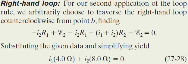
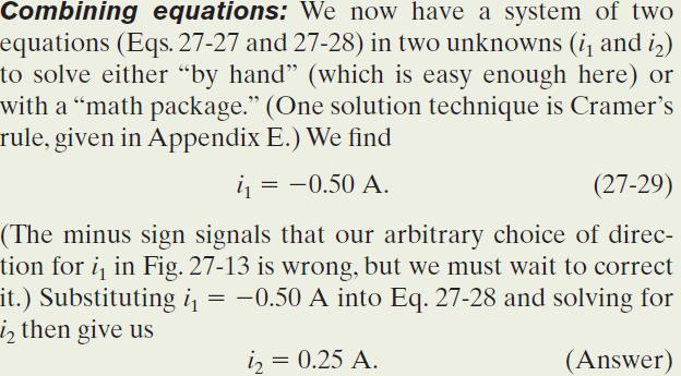
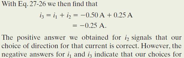
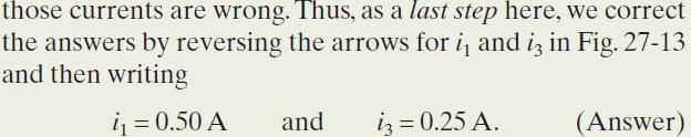
16 Example, Single loop circuit with two real batteries:


17 Example, Single loop circuit with two real batteries, cont.:

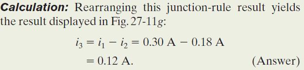
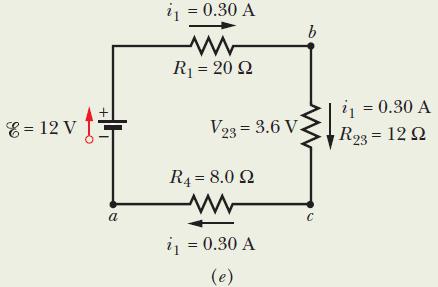
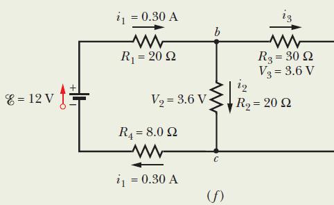
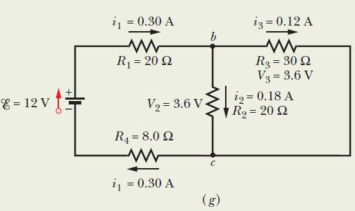
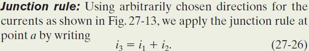
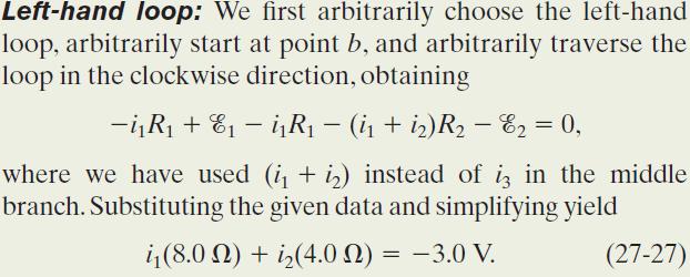
18 27.7: Multi-loop Circuits: Consider junction d in the circuit. Incoming currents i 1 and i 3, and it leaves via outgoing current i 2. Since there is no variation in the charge at the junction, the total incoming current must equal the total outgoing current: This rule is often called Kirchhoff s junction rule (or Kirchhoff s current law). For the left-hand loop, For the right-hand loop, And for the entire loop, The junction rule is a consequence of charge conservation
19 Resistors in Parallel Resistors are in parallel when they are across the same potential difference; they can again be replaced by a single equivalent resistance:
20 Resistors in Parallel Using the fact that the potential difference across each resistor is the same, and the total current is the sum of the currents in each resistor, we find: Note that this equation gives you the inverse of the resistance, not the resistance itself!


21 27.7: Multi-loop Circuits, Resistors in Parallel: where V is the potential difference between a and b. From the junction rule,

22 27.7: Multi-loop Circuits:
23 Resistors in Series and Parallel If a circuit is more complex, start with combinations of resistors that are either purely in series or in parallel. Replace these with their equivalent resistances; as you go on you will be able to replace more and more of them.


24 Example, Resistors in Parallel and in Series:


25 Example, Resistors in Parallel and in Series, cont.:
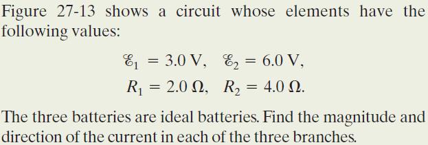
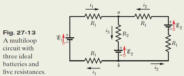
26 Example, Multi-loop circuit and simultaneous loop equations:
27 27.8: Ammeter and Voltmeter: An instrument used to measure currents is called an ammeter. It is essential that the resistance R A of the ammeter be very much smaller than other resistances in the circuit. A meter used to measure potential differences is called a voltmeter. It is essential that the resistance R V of a voltmeter be very much larger than the resistance of any circuit element across which the voltmeter is connected.
28 RC Circuits In a circuit containing only batteries and capacitors, charge appears almost instantaneously on the capacitors when the circuit is connected. However, if the circuit contains resistors as well, this is not the case.

29 27.9: RC Circuits, Charging a Capacitor: It turns out that: We know that:
30 27.9: RC Circuits, Time Constant: The product RC is called the capacitive time constant of the circuit and is represented with the symbol τ: At time t= τ =( RC), the charge on the initially uncharged capacitor increases from zero to: During the first time constant τ the charge has increased from zero to 63% of its final value CE.
31 27.9: RC Circuits, Discharging a Capacitor: Assume that the capacitor of the figure is fully charged to a potential V 0 equal to the emf of the battery E. At a new time t =0, switch S is thrown from a to b so that the capacitor can discharge through resistance R. Fig (b) This shows the decline of the charging current in the circuit. The curves are plotted for R =2000 Ω, C =1 μf, and E =10 V; the small triangles represent successive intervals of one time constant τ.
Chapter 28. Direct Current Circuits
 Chapter 28 Direct Current Circuits Direct Current When the current in a circuit has a constant magnitude and direction, the current is called direct current Because the potential difference between the
Chapter 19: DC Circuits
 Chapter 19: DC Circuits EMF and Terminal Voltage Resistors in Series and in Parallel Kirchhoff s Rules EMFs in Series and in Parallel; Charging a Battery Capacitors in Series and in Parallel RC Circuits
CHAPTER 19 DC Circuits Units
 CHAPTER 19 DC Circuits Units EMF and Terminal Voltage Resistors in Series and in Parallel Kirchhoff s Rules EMFs in Series and in Parallel; Charging a Battery Circuits Containing Capacitors in Series and
Direct-Current Circuits
 Chapter 26 Direct-Current Circuits PowerPoint Lectures for University Physics, 14th Edition Hugh D. Young and Roger A. Freedman Lectures by Jason Harlow Learning Goals for Chapter 26 Looking forward at
COLLEGE PHYSICS Chapter 21 CIRCUITS, BIOELECTRICITY, AND DC INSTRUMENTS
 COLLEGE PHYSICS Chapter 21 CIRCUITS, BIOELECTRICITY, AND DC INSTRUMENTS Resistances in Series, Parallel, and Series Parallel Combinations Resistors in series all have the same current. Resistances in Series,
Lecture 5, 7/19/2017. Review: Kirchhoff s Rules Capacitors in series and in parallel. Charging/Discharging capacitors. Magnetism
 Lecture 5, 7/19/2017 Review: Kirchhoff s Rules Capacitors in series and in parallel. Charging/Discharging capacitors. Magnetism Find the current drawn by this circuit. Kirchhoff s Rules Kirchhoff s rules:
AP Physics B Ch 18 and 19 Ohm's Law and Circuits
 Name: Period: Date: AP Physics B Ch 18 and 19 Ohm's Law and Circuits MULTIPLE CHOICE. Choose the one alternative that best completes the statement or answers the question. 1) A device that produces electricity
Chapter 19: Direct Current Circuits
 Chapter 19: Direct Current Circuits In this chapter we will explore circuits with batteries, resistors, and capacitors In this course, we will only consider: Direct current circuit where the current is
Chapter 21 Electric Current and Direct- Current Circuits
 Chapter 21 Electric Current and Direct- Current Circuits Menu Electric Current Resistance and Ohm s Law Energy and Power in Electric Circuits Resistors in Series and Parallel HW # 5 Pg. 754 759: # 7, 8,
Lecture PowerPoints. Chapter 19 Physics: Principles with Applications, 6 th edition Giancoli
 Lecture PowerPoints Chapter 19 Physics: Principles with Applications, 6 th edition Giancoli 2005 Pearson Prentice Hall This work is protected by United States copyright laws and is provided solely for
10/23/2016. Circuit Diagrams. Circuit Diagrams. Circuit Elements
 Circuit Diagrams The top figure shows a literal picture of a resistor and a capacitor connected by wires to a battery. The bottom figure is a circuit diagram of the same circuit. A circuit diagram is a
Chapter 26 DC Circuits. Copyright 2009 Pearson Education, Inc.
 Chapter 26 DC Circuits 26-1 EMF and Terminal Voltage Electric circuit needs battery or generator to produce current these are called sources of emf. Battery is a nearly constant voltage source, but does
Chapter 26 DC Circuits
 Chapter 26 DC Circuits Electric circuit needs battery or generator to produce current these are called sources of emf. Battery is a nearly constant voltage source, but does have a small internal resistance,
Current Electricity. GRADE 10 PHYSICAL SCIENCE Robyn Basson CAPS
 Current Electricity GRADE 10 PHYSICAL SCIENCE Robyn Basson CAPS What is current electricity? The flow of moving charge, usually carried by moving electrons in a wire. Circuits A path in which charges continually
Series and Parallel Networks
 Series and Parallel Networks Department of Physics & Astronomy Texas Christian University, Fort Worth, TX January 17, 2014 1 Introduction In this experiment you will examine the brightness of light bulbs
Q2. The diagram shows a network of four 2 Ω resistors. The effective resistance, in Ω, between X and Y is A 0.5 B 1.2 C 1.7. D 2.
 Q1. Three identical cells, each of internal resistance R, are connected in series with an external resistor of resistance R. The current in the external resistor is I. If one of the cells is reversed in
Sharjah Indian School Sharjah Boys Wing
 Read the instructions given below carefully before writing the fair record book. The following details are to be written on the LEFT HAND SIDE of the book. CIRCUIT DIAGRAM CALCULATIONS The remaining details
RL Circuits Challenge Problems
 RL Circuits Challenge Problems Problem : RL Circuits Consider the circuit at left, consisting of a battery (emf ε), an inductor L, resistor R and switch S. For times t< the switch is open and there is
SOURCES OF EMF AND KIRCHHOFF S LAWS
 SOURCES OF EMF AND KIRCHHOFF S LAWS VERY SHORT ANSWER QUESTIONS 1. What is the SI unit of (i) emf (ii) terminal potential difference? 2. When an ammeter is put in series in a circuit, does it read slightly
Electromagnetic Induction, Faraday s Experiment
 Electromagnetic Induction, Faraday s Experiment A current can be produced by a changing magnetic field. First shown in an experiment by Michael Faraday A primary coil is connected to a battery. A secondary
16.3 Ohm s Law / Energy and Power / Electric Meters
 16.3 Ohm s Law / Energy and Power / Electric Meters Voltage Within a battery, a chemical reaction occurs that transfers electrons from one terminal to another terminal. This potential difference across
Chapter 19. DC Circuits
 Ch-19-1 Chapter 19 Questions DC Circuits 1. Explain why birds can sit on power lines safely, even though the wires have no insulation around them, whereas leaning a metal ladder up against a power line
LABORATORY 2 MEASUREMENTS IN RESISTIVE NETWORKS AND CIRCUIT LAWS
 LABORATORY 2 MEASUREMENTS IN RESISTIVE NETWORKS AND CIRCUIT LAWS The objective of this experiment is to provide working knowledge of the ammeter, voltmeter, and ohmmeter as well as their limitations in
INVESTIGATION ONE: WHAT DOES A VOLTMETER DO? How Are Values of Circuit Variables Measured?
 How Are Values of Circuit Variables Measured? INTRODUCTION People who use electric circuits for practical purposes often need to measure quantitative values of electric pressure difference and flow rate
15 Electrical Circuits Name Worksheet A: SERIES CIRCUIT PROBLEMS
 Worksheet A: SERIES CIRCUIT PROBLEMS be careful to use proper significant figures on all answers 1. What would be the required voltage of an energy source in a circuit with a current of 10.0 A and a resistance
Circuits-Circuit Analysis
 Base your answers to questions 1 through 3 on the information and diagram below. 4. A 9-volt battery is connected to a 4-ohm resistor and a 5-ohm resistor as shown in the diagram below. A 3.0-ohm resistor,
Circuit Analysis Questions A level standard
 1. (a) set of decorative lights consists of a string of lamps. Each lamp is rated at 5.0 V, 0.40 W and is connected in series to a 230 V supply. Calculate the number of lamps in the set, so that each lamp
Chapter Assessment Use with Chapter 22.
 Date Period 22 Use with Chapter 22. Current Electricity Understanding Concepts Part A Use each of the following terms once to complete the statements below. ampere electric current potential difference
Write the term that correctly completes the statement. Use each term once. ampere. electric current. resistor battery.
 Date Period Name CHAPTER 22 Study Guide Current Electricity Vocabulary Review Write the term that correctly completes the statement. Use each term once. ampere electric current resistor battery kilowatt-hour
Higher - Electricity Powerpoint Answers
 Higher - Electricity Powerpoint Answers 1. Electrical current is defined as the number of coulombs of charge that pass a point per second. 2. Potential difference is defined as the energy given to each
Principles of Electrical Engineering
 D.C GENERATORS Principle of operation of D.C machines, types of D.C Generators, e.m.f equation of D.C Generator, O.C.C of a D.C Shunt Generator, Load characteristics of D.C.Generators GENERATOR PRINCIPLE:
 1 (a) (i) State what is meant by the direction of an electric field....[1] Fig. 9.1 shows a pair of oppositely-charged horizontal metal plates with the top plate positive. Fig. 9.1 The electric field between
Series and Parallel Circuits
 Series and Parallel Circuits 1 of 23 Boardworks Ltd 2016 Series and Parallel Circuits 2 of 23 Boardworks Ltd 2016 What are series and parallel circuits? 3 of 23 Boardworks Ltd 2016 Circuit components can
ELECTRICITY: INDUCTORS QUESTIONS
 ELECTRICITY: INDUCTORS QUESTIONS No Brain Too Small PHYSICS QUESTION TWO (2017;2) In a car engine, an induction coil is used to produce a very high voltage spark. An induction coil acts in a similar way
PhysicsAndMathsTutor.com 1
 Q1. A battery of emf 9.0 V and internal resistance, r, is connected in the circuit shown in the figure below. (a) The current in the battery is 1.0 A. (i) Calculate the pd between points A and B in the
Motional emf. as long as the velocity, field, and length are mutually perpendicular.
 Motional emf Motional emf is the voltage induced across a conductor moving through a magnetic field. If a metal rod of length L moves at velocity v through a magnetic field B, the motional emf is: ε =
EXPERIMENT - 1 OHM S LAW
 NOTE: While you copy the practical record see that you are following the note. Write Aim, theory, materials required, procedure, results, discussion and precautions on the right side of your record. While
PAPER 2 THEORY QUESTIONS
 PAPER 2 THEORY QUESTIONS 1 A plastic rod is rubbed with a cloth and becomes negatively charged. (a) Explain how the rod becomes negatively charged when rubbed with a cloth... [2] (b) An uncharged metal-coated
Chapter 31. Faraday s Law
 Chapter 31 Faraday s Law Michael Faraday 1791 1867 British physicist and chemist Great experimental scientist Contributions to early electricity include: Invention of motor, generator, and transformer
CHAPTER 2 ELECTRIC CIRCUIT
 CHAPTE 2 ELECTIC CICUIT 1 Electric charges Two kinds of charges Who carry those charges? Unit of charge 2 Flow of charge and electric current The true picture of a circuit Page 1 The conventional picture
Electric current, resistance and voltage in simple circuits
 Lab 6: Electric current, resistance and voltage in simple circuits Name: Group Members: Date: T s Name: pparatus: ulb board with batteries, connecting wires, two identical bulbs and a different bulb, a
Basic Circuits Notes- THEORY. An electrical circuit is a closed loop conducting path in which electrical current flows
 Basic Circuits Notes- THEORY NAME: An electrical circuit is a closed loop conducting path in which electrical current flows Now how does a circuit work? In order to get the water flowing, you d need a
2-1. Terms and Characteristics. Description of Terms Cooling Performance of the Automotive IGBT Module
 Chapter 2 Terms and Characteristics 1. 2. Description of Terms Cooling Performance of the Automotive IGBT Module 2-5 2-2 2-1 This chapter describes the terms related to the automotive IGBT module and its
Update. This week A. B. Kaye, Ph.D. Associate Professor of Physics. Michael Faraday
 10/26/17 Update Last week Completed Sources of Magnetic Fields (Chapter 30) This week A. B. Kaye, Ph.D. Associate Professor of Physics (Chapter 31) Next week 30 October 3 November 2017 Chapter 32 Induction
Level 3 Physics: Demonstrate understanding of electrical systems Batteries and Kirchoff s Laws - Answers
 Level 3 Physics: Demonstrate understanding of electrical systems Batteries and Kirchoff s Laws - Answers In 03, AS 956 replaced AS 9053. The Mess that is NCEA Assessment Schedules. In AS 9053 there was
V=I R P=V I P=I 2 R. E=P t V 2 R
 Circuit Concepts Learners should be able to: (a) draw, communicate and analyse circuits using standard circuit symbols using standard convention (b) apply current and voltage rules in series and parallel
Today s lecture: Generators Eddy Currents Self Inductance Energy Stored in a Magnetic Field
 PHYSICS 1B Today s lecture: Generators Eddy Currents Self Inductance Energy Stored in a Magnetic Field PHYSICS 1B Lenz's Law Generators Electric generators take in energy by work and transfer it out by
Lab 9: Faraday s and Ampere s Laws
 Lab 9: Faraday s and Ampere s Laws Introduction In this experiment we will explore the magnetic field produced by a current in a cylindrical coil of wire, that is, a solenoid. In the previous experiment
Physics Work with your neighbor. Ask me for help if you re stuck. Don t hesistate to compare notes with nearby groups.
 Physics 9 2016-04-13 Work with your neighbor. Ask me for help if you re stuck. Don t hesistate to compare notes with nearby groups. Today we ll build on what we did Monday with batteries and light bulbs.
Higher Homework One Part A. 1. Four resistors, each of resistance 20Ω, are connected to a 60V supply as shown.
 Higher Homework One Part A 1. Four resistors, each of resistance 20Ω, are connected to a 60V supply as shown. a) Calculate the total resistance of the circuit. b) Calculate the current drawn from the supply.
Laboratory Exercise 12 THERMAL EFFICIENCY
 Laboratory Exercise 12 THERMAL EFFICIENCY In part A of this experiment you will be calculating the actual efficiency of an engine and comparing the values to the Carnot efficiency (the maximum efficiency
ELECTRICITY & MAGNETISM - EXAMINATION QUESTIONS (4)
") ELECTRICITY & MAGNETISM - EXAMINATION QUESTIONS (4) 1. Which two electrical quantities are measured in volts? A current and e.m.f. B current and resistance C e.m.f. and potential difference D potential
ELECTRICITY & MAGNETISM - EXAMINATION QUESTIONS (4) 1. Which two electrical quantities are measured in volts? A current and e.m.f. B current and resistance C e.m.f. and potential difference D potential
Ohm s Law. 1-Introduction: General Physics Laboratory (PHY119) Basic Electrical Concepts:
 Basic Electrical Concepts:") Ohm s Law General Physics Laboratory (PHY119) 1-Introduction: Basic Electrical Concepts: 1- Current (I): Is the flow of electrons through a conductor or semiconductor. For current to flow, it requires
Ohm s Law General Physics Laboratory (PHY119) 1-Introduction: Basic Electrical Concepts: 1- Current (I): Is the flow of electrons through a conductor or semiconductor. For current to flow, it requires
Chapter 21 Practical Electricity
 Chapter 21 Practical Electricity (A) Electrical Power 1. State four applications of the heating effect of electricity. Home: o Used in electric kettles o Used in electric irons o Used in water heaters
Chapter 29 Electromagnetic Induction
 Chapter 29 Electromagnetic Induction Lecture by Dr. Hebin Li Goals of Chapter 29 To examine experimental evidence that a changing magnetic field induces an emf To learn how Faraday s law relates the induced
Name: Base your answer to the question on the information below and on your knowledge of physics.
 Name: Figure 1 Base your answer to the question on the information below and on your knowledge of physics. A student constructed a series circuit consisting of a 12.0-volt battery, a 10.0-ohm lamp, and
Name Period. (c) Now replace the round bulb(s) with long bulb(s). How does the brightness change?
 Now replace the round bulb(s) with long bulb(s). How does the brightness change?") Name Period P Phys 1 Discovery Lesson Electric Circuits 2.1 Experiment: Charge Flow Strength & Resistors circuit is an unbroken loop of conductors. Charge (q) can flow continuously in a circuit. If an
Name Period P Phys 1 Discovery Lesson Electric Circuits 2.1 Experiment: Charge Flow Strength & Resistors circuit is an unbroken loop of conductors. Charge (q) can flow continuously in a circuit. If an
Laboratory 5: Electric Circuits Prelab
 Phys 132L Fall 2018 Laboratory 5: Electric Circuits Prelab 1 Current and moving charges Atypical currentinanelectronic devicemightbe5.0 10 3 A.Determinethenumber of electrons that pass through the device
PHYSICS MCQ (TERM-1) BOARD PAPERS
 BOARD PAPERS") GRADE: 10 PHYSICS MCQ (TERM-1) BOARD PAPERS 1 The number of division in ammeter of range 2A is 10 and voltmeter of range 5 V is 20. When the switch of the circuit given below is closed, ammeter reading
GRADE: 10 PHYSICS MCQ (TERM-1) BOARD PAPERS 1 The number of division in ammeter of range 2A is 10 and voltmeter of range 5 V is 20. When the switch of the circuit given below is closed, ammeter reading
AP Physics B: Ch 20 Magnetism and Ch 21 EM Induction
 Name: Period: Date: AP Physics B: Ch 20 Magnetism and Ch 21 EM Induction MULTIPLE CHOICE. Choose the one alternative that best completes the statement or answers the question. 1) If the north poles of
APPLICATION NOTE QuickStick 100 Power Cable Sizing and Selection
 APPLICATION NOTE QuickStick 100 Power Cable Sizing and Selection Purpose This document will provide an introduction to power supply cables and selecting a power cabling architecture for a QuickStick 100
Experiment 5 Shunt DC Motor (I)
") Objective To determine the torque-speed and efficiency characteristic curves. To f out how to reverse the direction of rotation of a shunt dc motor. Introduction shunt dc motor is essentially the same
Objective To determine the torque-speed and efficiency characteristic curves. To f out how to reverse the direction of rotation of a shunt dc motor. Introduction shunt dc motor is essentially the same
ELECTROMAGNETIC INDUCTION. FARADAY'S LAW
 1. Aim. Physics Department Electricity and Magnetism Laboratory. ELECTROMAGNETIC INDUCTION. FARADAY'S LAW Observe the effect of introducing a permanent magnet into a coil. Study what happens when you introduce
Figure 1: (a) cables with alligator clips and (b) cables with banana plugs.
 cables with alligator clips and (b) cables with banana plugs.") Ohm s Law Safety and Equipment Computer with PASCO Capstone, PASCO 850 Universal Interface Double banana/alligator Cable, 2 Alligator Wires PASCO Voltage Sensor Cable Multimeter with probes. Rheostat Ruler
Ohm s Law Safety and Equipment Computer with PASCO Capstone, PASCO 850 Universal Interface Double banana/alligator Cable, 2 Alligator Wires PASCO Voltage Sensor Cable Multimeter with probes. Rheostat Ruler
UNISONIC TECHNOLOGIES CO., LTD UC5301
 UNISONIC TECHNOLOGIES CO., LTD UC5301 SWITCHED-CAPACITOR VOLTAGE INVERTERS DESCRIPTION The UTC UC5301 is an unregulated charge-pump voltage inverter. It can be used to generate a negative supply from positive
Review: Magnetic Flux, EMF
 Announcements Professor Reitze taking over for the rest of the semester Occasional classes by Professor Kumar WebAssign HW Set 7 due the Friday Problems cover material from Chapters 20 and 21 Tea and Cookies
UNIT 2. INTRODUCTION TO DC GENERATOR (Part 1) OBJECTIVES. General Objective
 OBJECTIVES. General Objective") DC GENERATOR (Part 1) E2063/ Unit 2/ 1 UNIT 2 INTRODUCTION TO DC GENERATOR (Part 1) OBJECTIVES General Objective : To apply the basic principle of DC generator, construction principle and types of DC generator.
DC GENERATOR (Part 1) E2063/ Unit 2/ 1 UNIT 2 INTRODUCTION TO DC GENERATOR (Part 1) OBJECTIVES General Objective : To apply the basic principle of DC generator, construction principle and types of DC generator.
PHYSICS 111 LABORATORY Experiment #3 Current, Voltage and Resistance in Series and Parallel Circuits
 PHYSCS 111 LABORATORY Experiment #3 Current, Voltage and Resistance in Series and Parallel Circuits This experiment is designed to investigate the relationship between current and potential in simple series
Almost 200 years ago, Faraday looked for evidence that a magnetic field would induce an electric current with this apparatus:
 Chapter 21 Electromagnetic Induction and Faraday s Law Chapter 21 Induced EMF Faraday s Law of Induction; Lenz s Law EMF Induced in a Moving Conductor Changing Magnetic Flux Produces an E Field Inductance
Introduction: Electromagnetism:
 This model of both an AC and DC electric motor is easy to assemble and disassemble. The model can also be used to demonstrate both permanent and electromagnetic motors. Everything comes packed in its own
Electromagnetic Induction Chapter Questions. 1. What is the Electromagnetic Force (EMF)? What are the units of EMF?
? What are the units of EMF?") Electromagnetic Induction Chapter Questions 1. What is the Electromagnetic Force (EMF)? What are the units of EMF? 2. The discovery of electric currents generating an magnetic field led physicists to look
Electromagnetic Induction Chapter Questions 1. What is the Electromagnetic Force (EMF)? What are the units of EMF? 2. The discovery of electric currents generating an magnetic field led physicists to look
Principles and types of analog and digital ammeters and voltmeters
 Principles and types of analog and digital ammeters and voltmeters Electrical voltage and current are two important quantities in an electrical network. The voltage is the effort variable without which
LAB 7. SERIES AND PARALLEL RESISTORS
 Name: LAB 7. SERIES AND PARALLEL RESISTORS Problem How do you measure resistance, voltage, and current in a resistor? How are these quantities related? What is the difference between a series circuit and
Electrical Energy and Power Ratings
 Section 1 - From the Wall Socket Electrical Energy and ower Ratings Batteries and the mains are sources of electrical energy. Electrical appliances can then convert this into other forms of energy. e.g.
Physics 121 Practice Problem Solutions 11 Faraday s Law of Induction
 Physics 121 Practice Problem Solutions 11 Faraday s Law of Induction Contents: 121P11-1P, 3P,4P, 5P, 7P, 17P, 19P, 24P, 27P, 28P, 31P Overview Magnetic Flux Motional EMF Two Magnetic Induction Experiments
AT1084 5A Low Dropout Positive Voltage Regulator
 FEATURES DESCRIPTION Three-Terminal Adjustable or Fixed Output Output Current of 5A Low Dropout 1.3V at 5A Output Current Line Regulation: 0.04% Load Regulation: 0.2% Fast Transient Response OCP & OTP
CI-TI Contactors - VLT Frequency Converters
 MN.90.K1.02 - VLT is a registered Danfoss trademark 1 Description This data sheet is based on tests made in co-operation with Contactor Business from Danfoss Automatic Division and Danfoss Drives A/S.
Safe, fast HV circuit breaker testing with DualGround technology
 Safe, fast HV circuit breaker testing with DualGround technology Substation personnel safety From the earliest days of circuit breaker testing, safety of personnel has been the highest priority. The best
Section 6 HOW ARE VALUES OF CIRCUIT VARIABLES MEASURED?
 Section 6 HOW RE VUES OF CIRCUIT VRIBES MESURED? INTRODUCTION People who use electric circuits for practical purposes often need to measure quantitative values of electric pressure difference and flow
Academic Year
 EXCELLENCE INTERNATIONAL SCHOOL First Term, Work sheet (1) Grade (9) Academic Year 2014-2015 Subject: quantities Topics:- Static electricity - Eelectrical NAME: DATE: MULTIPLE CHOICE QUESTIONS: 1 - A circuit
SC10F Circuits Lab Name:
 SC10F Circuits Lab Name: Purpose: In this lab you will be making, both, series and parallel circuits. You will then be using a millimeter to take readings at various points in these circuits. Using these
The Mechanical Equivalent of Heat
 The Mechanical Equivalent of Heat INTRODUCTION One of the most famous experiments of the 19 th century was Joule s experiment showing that mechanical energy can be converted to heat. This showed that heat
Unit 9. (Filled In) Draw schematic circuit diagrams for resistors in series and in parallel
 Draw schematic circuit diagrams for resistors in series and in parallel") Name: Date: Period: Unit 9 Series & Parallel Circuits (Filled In) Essential Questions: Does adding resistors to a circuit always reduce current? Does adding more light bulbs to a circuit always make them
Name: Date: Period: Unit 9 Series & Parallel Circuits (Filled In) Essential Questions: Does adding resistors to a circuit always reduce current? Does adding more light bulbs to a circuit always make them
Electricity concepts teacher backgrounder
 Electricity concepts teacher backgrounder What is electricity, where does it come from and what do we use it for? Scientifically, electricity is the movement of electrons from one atom to another. This
Shunt Capacitor Bank Protection in UHV Pilot Project. Qing Tian
 Shunt Capacitor Bank Protection in UHV Pilot Project Qing Tian 2012-5 INTRODUCTION State Grid Corp. of China, the largest electric power provider in the country, has first build a 1000 kv transmission
Ch 20 Inductance and Faraday s Law 1, 3, 4, 5, 7, 9, 10, 11, 17, 21, 25, 30, 31, 39, 41, 49
 Ch 20 Inductance and Faraday s Law 1, 3, 4, 5, 7, 9, 10, 11, 17, 21, 25, 30, 31, 39, 41, 49 The coil with the switch is connected to a battery. (Primary coil) When current goes through a coil, it produces
Let's start our example problems with a D'Arsonval meter movement having a full-scale deflection rating of 1 ma and a coil resistance of 500 Ω:
 Voltmeter design As was stated earlier, most meter movements are sensitive devices. Some D'Arsonval movements have full-scale deflection current ratings as little as 50 µa, with an (internal) wire resistance
CHAPTER 2. Current and Voltage
 CHAPTER 2 Current and Voltage The primary objective of this laboratory exercise is to familiarize the reader with two common laboratory instruments that will be used throughout the rest of this text. In
Chapter 3. ECE Tools and Concepts
 Chapter 3 ECE Tools and Concepts 31 CHAPTER 3. ECE TOOLS AND CONCEPTS 3.1 Section Overview This section has four exercises. Each exercise uses a prototyping board for building the circuits. Understanding
Experimental Question 1: Levitation of Conductors in an Oscillating Magnetic Field
 Experimental Question 1: Levitation of Conductors in an Oscillating Magnetic Field In an oscillating magnetic field of sufficient strength, levitation of a metal conductor becomes possible. The levitation
EXPERIMENT CALIBRATION OF 1PHASE ENERGY METER
 EXPERIMENT CALIBRATION OF PHASE ENERGY METER THEORY:- Energy Meters are integrating instruments used to measure the quantity of electrical energy supplied to a circuit in a given time. Single phase energy
ELECTRICITY: ELECTROMAGNETISM QUESTIONS
 ELECTRICITY: ELECTROMAGNETISM QUESTIONS The flying fox (2017;3) Sam has a flying fox (zip line) that he wants to use in the dark. Sam connects a 12.0 V battery to a spotlight, using two 1.60-metre-long
SPEED CONTROL OF DC SHUNT MOTOR
 INDEX NO. : M-140 TECHNICAL MANUAL FOR SPEED CONTROL OF DC SHUNT MOTOR Manufactured by : PREMIER TRADING CORPORATION (An ISO 9001:2000 Certified Company) 212/1, Mansarover Civil Lines, MEERUT. Phone :
Lecture PowerPoints. Chapter 21 Physics: Principles with Applications, 7th edition, Global Edition Giancoli
 Lecture PowerPoints Chapter 21 Physics: Principles with Applications, 7th edition, Global Edition Giancoli This work is provided solely for the use of instructors in teaching their courses and assessing
BASIC ELECTRICAL MEASUREMENTS By David Navone
 BASIC ELECTRICAL MEASUREMENTS By David Navone Just about every component designed to operate in an automobile was designed to run on a nominal 12 volts. When this voltage, V, is applied across a resistance,
Batteries n Bulbs: Voltage, Current and Resistance (8/6/15) (approx. 2h)
 (approx. 2h)") Batteries n Bulbs: Voltage, Current and Resistance (8/6/15) (approx. 2h) Introduction A simple electric circuit can be made from a voltage source (batteries), wires through which current flows and a resistance,
Batteries n Bulbs: Voltage, Current and Resistance (8/6/15) (approx. 2h) Introduction A simple electric circuit can be made from a voltage source (batteries), wires through which current flows and a resistance,
Equivalent Meter Resistance
 Equivalent Meter Resistance This installation of N.E.R.D discusses meter resistance. The equipment referenced here is found in the Undergraduate Electronics Lab at the University of Houston. Topics covered
What does the measure? I
 TOP 17 urrent Electricity 1 Which of the following is a correct unit for electrical energy? 5 The diagrams show the symbols and ranges of five meters. ampere Which meter should be used to measure a current
Chapter 29 Electromagnetic Induction and Faraday s Law
 Chapter 29 Electromagnetic Induction and Faraday s Law 29.1 Induced EMF Units of Chapter 29 : 1-8 29.3 EMF Induced in a Moving Conductor: 9, 10 29.4 Electric Generators: 11 29.5 Counter EMF and Torque;
EXPERIMENT 4 OHM S LAW, RESISTORS IN SERIES AND PARALLEL
 220 4- I. THEOY EXPEIMENT 4 OHM S LAW, ESISTOS IN SEIES AND PAALLEL The purposes of this experiment are to test Ohm's Law, to study resistors in series and parallel, and to learn the correct use of ammeters