Wire Harness Installation Manual # Part # 60617
|
|
|
- Elinor Nelson
- 5 years ago
- Views:
Transcription

1 Wire Harness Installation Manual #90572 For Installing: Part # Circuit/7 Relay 4.8L-6.0 L w/4l60e Integrated Harnesses Perfect Performance Products, LLC Painless Performance Products Division 2501 Ludelle Street Fort Worth, TX phone fax Web Site: painless@painlessperformance.com
2 If you have any questions concerning the installation of this harness or having trouble in general, feel free to call Painless Performance Products' tech line at Calls are answered from 8am to 5pm central time, Monday thru Friday, except holidays. We have attempted to provide you with as accurate instructions as possible, and are always concerned about corrections or improvements that can be made. If you have found any errors or omissions, or if you simply have comments or suggestions concerning these instructions, please write us at the address above. Or, better yet, send us a fax at (817) or us at painless@painlessperformance.com. We sincerely appreciate your business. Perfect Performance Products, LLC shall in no event be liable in contract or tort (including negligence) for special, indirect, incidental, or consequential damages, such as but not limited to, loss of property damage, or any other damages, costs or expenses which might be claimed as the result of the use or failure of the goods sold hereby, except only the cost of repair or replacement. CAUTION: BEFORE THE REMOVAL OF YOUR ORIGINAL HARNESS AND/OR THE INSTALL OF YOUR NEW PAINLESS HARNESS, DISCONNECT THE POWER FROM YOUR VEHICLE BY REMOVING THE NEGATIVE AND POSITIVE BATTERY CABLES FROM THE BATTERY. THE BATTERY IS NOT TO BE CONNECTED UNTILL THE PAINLESS HARNESS HAS BEEN INSTALLED AND TESTED. A full color copy of these instructions can be found at Painless Performance Products recommends you, the installer, read this installation manual from front to back before installing this harness. Due to the variables involved with your particular installation, reading this manual will give you considerable insight on the proper installation of this harness. In the event that there are unused or unconnected wires, the ends of all unused wires will need to be terminated with an insulated terminal or taped. Doing so will prevent the wires from shorting and causing harness failure or fire. February 2010 Copyright By Perfect Performance Products, LLC 1
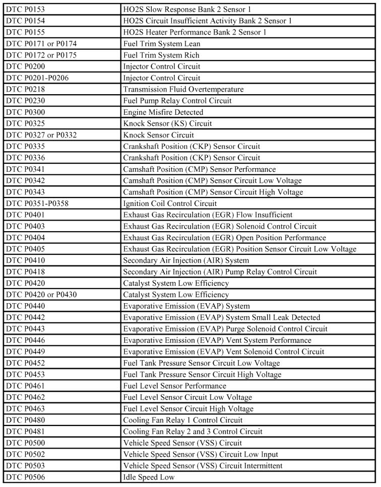
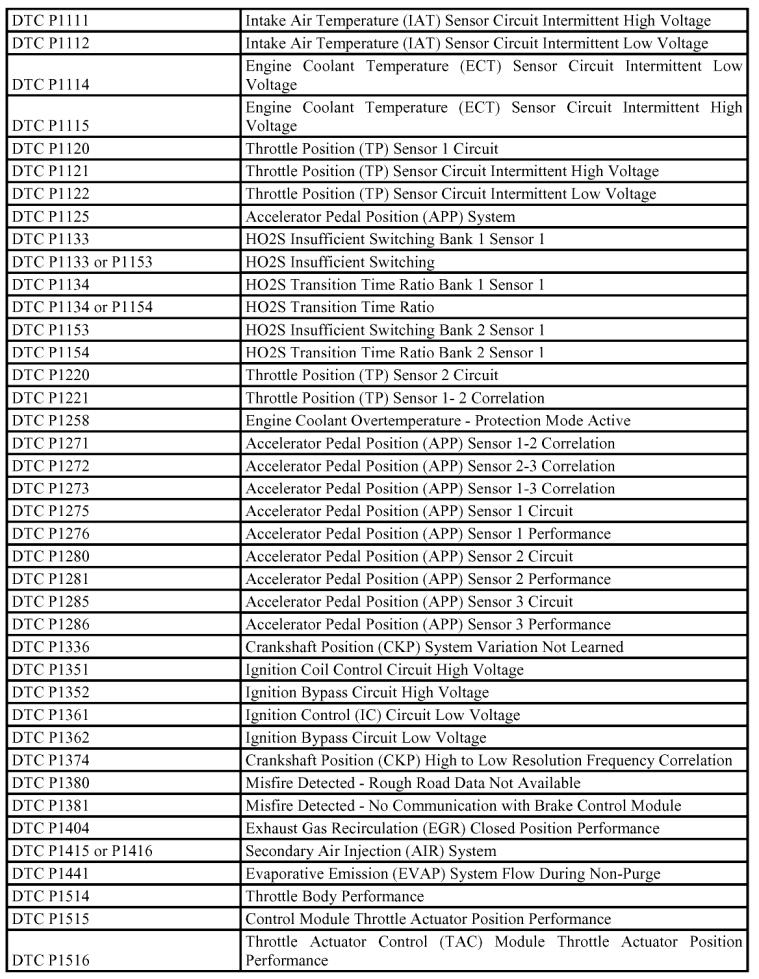
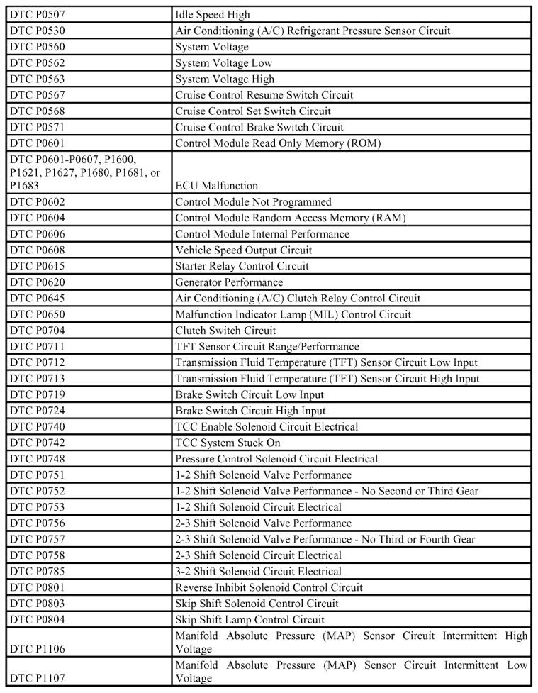
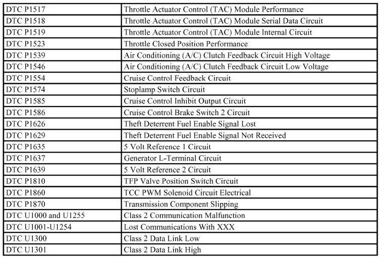
3 SECTIONS TABLE OF CONTENTS INTRODUCTION SMALL PARTS. 3 PCM BACKGROUND TOOLS NEEDED REQUIRED FUEL INJECTION PARTS.. 10 FUSEBLOCKMOUNTING MOUNTING THE PCM FUEL INJECTION HARNESS WIRING THE FRONT OF THE VEHICLE 28 WIRING THE INTERIOR OF THE VEHICLE WIRING THE REAR OF THE VEHICLE.. 42 TESTING THE SYSTEM WIRE INDEX DIAGNOSTIC TROUBLE CODES..49 ILLUSTRATIONS FUSE BLOCK 11 ENGINE GROUNDS.. 15 BATTERY POWER HEADLIGHT SECTION INSTRUMENT PANEL SECTION HEADLIGHT SWITCH TURN SWITCH COLUMN MOUNT IGNITION SWTICH DASH MOUNT IGNITION SWITCH A/C SWITCH CIRCUITS CRUISE SWITCH.. 39 BRAKE SWITCH COME/COURTESY LIGHT CIRCUITS. 40 INTERIOR GROUND SPLICE TAIL LIGHT SECTION TESTING THE SYSTEM
4 Introduction: This integrated chassis/fuel injection harness can be used to wire any vehicle with an 4.8L, 5.3L or 6.0L engine, 4L60E transmission and a chassis that utilizes switches, lighting and other circuits that are 12Volt and negative grounded. Fuel injection wires are also GM color. Chassis wires are color coded as any 1970s to 1980s General Motors vehicle would be. With this harness fitting such a wide range of vehicles, these instructions should be considered general installation procedures. Referring to a factory chassis wiring schematic of your vehicle will aid in connecting to factory switches, lighting and accessory equipment. Most manuals sold at auto parts chain stores provide a basic wire diagram. Please do not attempt to modify this Painless harness to function as your factory harness did. We have developed this harness to function as this manual instructs you to connect it. We suggest you make identification labels and apply them as you remove the old harness from your vehicle. Marking the sections, connectors and single wire connections during the removal gives you a great backup resource to use if you forget which wire goes where while installing this Painless harness. Be sure to retain any wiring pertaining to the following accessories as this Painless harness only provides fused power circuits for these: A/C-Heater selector switch, blower motor resistor and blower motor Power window motors, switches and relays Power door locks, switches and relays Contents of this Painless wire harness kit: Refer to the contents figure on the front page to take inventory. See that you have everything you re intended to have in this kit. If you find that anything is missing or damaged, please contact the dealer where you obtained the kit or Painless Performance at (800) This Painless Wire Harness Kit should contain the following: Wire harness 2 large parts bags containing heat shrink, 4 inch zip ties, 7 inch zip ties, umbrella zip ties, rubber alternator wire boot, rubber grommets GM turn signal switch connectors, GM ignition switch connectors, GM headlight switch and dimmer switch connectors and four H4 headlight connectors. 1 clear plastic, bubble pack, parts box containing miscellaneous ring terminals, spade terminals and several types of Packard terminals. Things to know about the Delphi Powertrain Control Module (PCM) utilized with this Painless harness: This harness requires the PCM to be flashed as a Camaro, because this calibration includes electric cooling fan relay operation and cruise control. The GM service # PCM was factory installed in many different makes and models of General Motors vehicles. Both V6 and V8 engines can be 3
5 operated by this controller. When procuring a PCM for use with this harness be sure to specify it be from a Camaro Z28 or Trans Am. The factory Camaro Z28 and Trans Am calibration incorporates a Vehicle Antitheft System (VATS). VATS must be turned off or otherwise the engine will continuously start for two seconds and then die, when cranked. Factory installed emission devices include: fuel tank pressure sensor, tank vent solenoid, tank purge solenoid, air pump, air pump solenoid, and exhaust gas recirculation solenoid. The calibration installed at the GM factory onto your PCM tells it to look for all of these emissions components. This Painless harness does not include any supporting wiring or connectors for these. The final drive ratio utilized in Camaro Z-28 and Trans Am cars was 3.23:1. The rear tire on these vehicles had an overall diameter of 25 inches. Transmission shift schedule calibrations are based around this rear end gear ratio and tire diameter. Most likely your rear end gear ratio and tire diameter is different than this. If so, without a calibration change to the transmission shift schedules your vehicle may up shift late/soon and down shift late/soon. You may also experience improper torque converter lock up operation. This Painless harness utilizes two cooling fan relays built into the fuse block. Both relays are controlled by the PCM. Fan 1 relay factory calibrations are 226 o F on and 219 o F off. Fan 2 relay factory calibrations are 234 o F on and 227 o F off. LS1/LS6 engines were factory installed with a coolant thermostat that opens at 195 o F. Aftermarket thermostats are available with a lower opening temperature. If you plan to use an aftermarket thermostat you must have both fan relay on/off temperature calibrations changed. We suggest an on temperature of 215 o F and off at 200 o F for fan 1 and 2. Non-electrical parts and other things you should consider when transplanting a Gen III engine and 4L60E transmission include: If your engine has not ran for several months or more you will probably experience the joy of clogged injectors when you go to fire it up for the first time. Do yourself a favor and have the injectors cleaned, or purchase new fuel injectors. If you do not, your engine will probably not start due to clogged fuel injectors. Gen III engines all came equipped with Delphi Multec injectors. Different part numbers have different lb/hr rated injectors. 4
6 Fuel system requirements include a high pressure, PSI, fuel pump. The fuel feed line to fuel rail must be at least -6AN or 3/8 in size for stock engine, HP, setups. If your engine s output is more than 450HP you should use - 8AN or ½ fuel rail feed line. Walbro manufactures a wide variety of high pressure fuel pumps and installation kits. They have many internet distributors including If your vehicle s fuel tank is one with the early small 1 & 13/16 hole sending unit you have several options of how to upgrade it. One option is to modify the sending unit yourself by adding a fuel return line. Another option is to replace the sending unit with an aftermarket one from a company such as They offer drop in units with a variety of tube sizes and adapter fittings. The other option is to have a company such as cut out the old flange and weld in a large flange from a later model 1984 & up GM vehicle. The larger flange will allow for an in tank mounted fuel pump. Gen III engines have return style fuel rails. External fuel pressure regulators are not required since the fuel rails have a built in one. You can plug the return line from the fuel pressure regulator on the fuel rail and mount an external vacuum biased regulator on the firewall. Make sure to adjust the fuel pressure to PSI. Gen III engine cooling systems have some specific requirements. First, the lower radiator hose connects to the water neck with the thermostat behind it. If looking at the front of the engine it is the water neck to the lower left of the water pump. The upper radiator hose connects to the water neck at the top of the water pump. Second, the factory coolant thermostat only starts to open at 195 o F and is fully open at 210 o F. Aftermarket thermostats are available that will open at a lower temperature. Third, these engines incorporate steam tubes that are plumbed into both the front and rear of each head. They are all tied together and then plumbed through the bottom of the throttle body and then to the radiator. Most people remove the throttle body from this coolant loop by connecting the steam tube outlet, which is located just the lower right of the throttle body and protruding forward from under the intake manifold, directly to the upper radiator hose or to an open coolant bung in the radiator. Do not plug off this steam tube, it must be connected to either the upper radiator hose or to the upper third of the radiator in order to bleed off any steam that accumulates in the engine heads. Companies such as Afco manufacture direct bolt in radiators that are specifically designed for Gen III engine transplants. These are ideal especially since the coolant inlet and outlet are both on the passenger side of the radiator. By moving the upper radiator inlet to the passenger side the driver side is opened up to allow a fresh air intake elbow to be routed there. Coolant temperature and oil pressure gauge senders can easily be connected to any Gen III engine. In both engine heads are threaded coolant ports with Metric 12 x 1.5 threads. The coolant port on the driver side head is utilized by the coolant temperature sensor needed for the PCM. The port on the passenger head usually has a plug in it that can be removed and a temperature sender for a 5
7 gauge can be inserted. Most aftermarket gauge manufacturers offer adapters to adapt their gauge sender so you can thread it into this coolant port. There are two places that oil pressure senders may be connected to these engines. Behind the intake manifold is a threaded port, Metric 16 x 1.5 threads. Depending on what vehicle your engine was donated from, this port might already have a 0-5 Volt oil pressure sensor in it. This Painless harness does not have connections for this sensor so you may remove it and with an adapter screw in your oil pressure gauge sender. Another spot that is common for oil pressure senders is just above the oil filter. Here you will find an aluminum cap with two hex head, 8mm bolts holding it to the oil pan. You can remove this cap, tap it to the threads that match your oil pressure sender and then reinstall it. Just keep in mind that if you plan to use headers this location for a sender may not be ideal. Heat can kill a sender quick. 4L60E transmissions require external fluid coolers. The ports on the side of the transmission usually have quick-connect fittings installed. Most local auto parts suppliers will offer fittings that adapt these ports to pipe flare fittings. If you plan to bend your own hard lines this is your best bet. Or, you can also screw in 3/8 NPT fittings into these ports. Make sure to use Teflon tape on the threads for a good seal. Fittings are available from many online retailers or your local hydraulic hose shop that are male 3/8 NPT to male -6AN or whatever your application may need. Shifter detents are another thing to consider when transplanting a 4L60E into a vehicle that was originally manufactured with a 2 or 3 speed transmission. Companies such as Shiftworks manufacture shifter conversion kits to upgrade your factory shifter to operate your late model transmission. Another option is to completely replace the shifter with an aftermarket one such as Lokar part # FMS64L60EEM. Throttle cables originally installed to your transplant vehicle may or may not be long enough to reach the throttle body. If it is not long enough or just doesn t seem to work properly because it is worn out/frayed then check out Lokar and their universal LS series throttle cables. These are cut to fit and easy to install. Engine accessory and frame clearance always seems to be an issue that comes up when transplanting a Gen III engine into any early model vehicle. Usually the alternator and power steering pumps do not have any clearance issues associated with them. The factory A/C compressor mounts to the passenger lower side of the engine. In this location, it will not clear most GM frames. You will either have to notch the frame to create clearance or move the A/C compressor. Companies such as KWIK Performance offer relocation brackets that move the compressor to the upper passenger side of the engine. Moving the compressor to this location works well with most transplants. These kits utilize a Sanden style compressor. Drive shaft length will have to be modified if you are upgrading to a 4L60E from most 2 & 3 speed automatics or manuals. You should also consider having the entire tube upgraded to a thicker wall material since you are likely to exceed the handling capabilities of the original tube. 6


8 Tools Needed: In addition to regular hand tools such as ratchets, sockets, extensions, screw drivers, flash light or drop light, you will need the following tools: Wire Crimping and Stripping Tools: Two types of crimping tools are needed to install this harness. The jaw style of crimp tool shown below can be purchased from under part number You will need this style of crimper to crimp the terminals used with GM turn signal, ignition, headlight and dimmer switches. The second style of hand crimper shown below can be purchased from just about any local electrical supply shop, home improvement store or can also be purchased online. You will need this style of crimper to crimp the heat shrinkable, insulated terminals included in the small parts bubble pack. A good set of wire strippers are required to strip wire properly. Shown below are a pair of strippers manufactured by Klein tools and that are available from just about any local electrical supply shop, home improvement store or can be purchase online. This style of wire stripper is ideal for this harness install because of its ability to properly strip wire gauges 10awg to 20awg. 7

9 Volt/Ohm Meter: A Volt/Ohm meter is always a good tool to have on hand when installing any type of electrical components into any vehicle. Most basic units provide the two functions required to diagnose most electrical issues seen during a harness install. These two functions are the ability to read DC Voltage and electrical continuity or Ohms. They can be purchased from any home improvement store, local hardware store and electrical supply shop and online. Battery Charger: A battery charger is a very useful tool to have when initially connecting power up to a newly installed wire harness. Battery chargers are available from any auto parts, sporting, home improvement or local electrical supply store. Be sure the charger you purchase has a low (5-10 Amps) setting. 8


10 How to use jaw style crimpers: 9
11 Parts required for installation of this harness: The Gen III engine and 4L60E transmission section of the wire harness requires the following parts for proper installation and operation. Factory installed engine sensors, injectors and coils should be perfect matches for this harness. Do not purchase the parts listed below unless you are missing it or need to replace a faulty one. Part Description Part Number Engine Gen III (Mechanical Throttle) Transmission 1997 & UP 4L60E PCM (Powertrain Control Module) GM Service # Fuel Injectors Delphi Multec Ignition Coils Delco D580 Throttle Position Sensor Delco Idle Air Control Delco Engine Coolant Temperature Sensor Delco Mass Air Flow/IAT Sensor GM Service # Cam Position Sensor Delco Crank Position Sensor Delco Knock Sensor Delco Oxygen Sensor Delco AFS106 PRNDL Switch GM # Vehicle Speed Sensor Delco Cruise Control Module GM # Cruise Control Cable GM # Manifold Absolute Pressure Sensor Delco

12 Mounting the fuse block: The 26 fuse 7 relay fuse block is the center point of this integrated harness. All power is routed through this fuse block. The first step to installing this integrated harness is to mount the fuse block. Remove the front cover from the fuse block. If looking at the front of the fuse block you will see a mounting hole on the lower right side. Use a bolt and this hole to secure this fuse block if possible. Another option for mounting this fuse block will require you to remove the rear cover from it. Insert a small, flat screw driver into the red slots as labeled in the picture below. Push the screw driver about ½ into the slot, gently pry on the screw driver handle towards the center of the fuse block while at the same time pulling the rear cover away from the fuse block. Do this for all four release slots. Once the rear cover is released from the main body of the fuse block you may notice the need to cut the tie wraps around the wires protruding from it in order to completely remove it. If so, cut the tie wraps and completely remove the rear cover from the fuse block. The front cover and rear cover will click together without the fuse block in between them. Just line them up and push them together until you hear the two locks click. You now have an accurate mock up of the fuse block to aid you when figuring out where to mount it. You can now make a custom bracket or just run some self tapping screws through it to hold this rear cover in its mounting place. Be sure any mounting solution you use does not distort the rear cover or introduce any sharp metal objects that could short out wires when you reassemble the fuse block. 11
 of harness between the main harness body and the PCM connectors. The harness also provides 3 feet (1 meter) of harness between the PCM harness breakout and the fuse block.")
13 Mounting the Powertrain Control Module: The Delphi PCM utilized with this harness must be securely mounted away from excessive heat, water or oil and road debris. We provide 5 feet (1.5 meters) of harness between the main harness body and the PCM connectors. The harness also provides 3 feet (1 meter) of harness between the PCM harness breakout and the fuse block. So, finding a spot to mount the PCM should not be a problem. Custom mounting brackets will be required. Behind the dash board is always a good place to mount the PCM. Depending on your dash board and whether or not your a/c evaporator box will allow for it, you most likely can mount the PCM here. Under the passenger seat is another good place to mount the PCM. The 5ft of harness should allow you to mount the PCM here. Just be sure the seat has enough clearance below it to not crush, scrape or damage the PCM or harness. On some vehicles, behind the passenger kick panel, there is a cubby hole large enough to mount the PCM. If your vehicle has this cubby hole feel free to mount the PCM there. Engine compartments usually have ample room that can be used for PCM mount places. For instance, many vehicles have large cubby holes between the inner fender, out fender and firewall. Sometimes this area is used for a/c evaporators and blower motor mounting; so make sure the space does not already have a planned occupation. 12
14 Harness routing and attachment: Now that the fuse block and PCM are mounted you can move on to routing the harness sections to their respective automobile locales. Take your time, leave enough slack in the harness to accommodate body/engine/chassis movement and keep the harness away from moving and/or hot parts. This complete wiring system, as well as this instruction manual, has been designed with five major groups incorporated into it. These groups are as follows. Engine section: This sections wires are to be routed out the center of the firewall, into the engine compartment, and then to their respective component. Includes wires and/or connectors that connect to the following: injectors, coils, engine coolant temperature sensor, alternator, throttle position sensor, idle air control, cam position sensor, manifold absolute pressure sensor, knock sensors, intake air temperature sensor, mass air flow sensor, crank position sensor, vehicle speed sensor, transmission solenoid pack, transmission mounted PRNDL switch, driver and passenger pre-catalytic converter oxygen sensors, starter, a/c compressor, oil pressure gauge sending unit, coolant temperature gauge sender and two engine grounds. Dash section: Includes fuse block, turn and hazard flashers, a horn relay, an interior ground connection, and the appropriate wires to connect the following: a/c-heater switch, wiper switch, ignition switch, headlight switch, turn signal switch, dimmer switch, cruise control switch, radio, gauge cluster, cigar lighter, courtesy lights, OBD-2 diagnostic port w/check engine light, driver and passenger power window/lock and speaker wires. PCM section: This section is to be routed to the powertrain control module. Includes blue and red, 80 pin connectors for the powertrain control module. Headlight section: This section is to be routed out the driver side of the firewall, into the engine compartment, and then to their respective components. Includes wires and/or connectors that connect to the following: high and low beam headlights, turn lights, park lights, grounds, brake switch, cooling fan 1 & 2, wiper motor, cruise control module and horn. Tail section: This section is to be routed to the rear of the vehicle. You can either route this section out into the engine compartment and then to the rear of the vehicle or route it under the door sill plate and then to the rear of the vehicle. Includes wires that connect to the following: fuel sending unit, electric fuel pump power wire, reverse lights, left turn/brake/tails, license plate light, right turn/brake/tail lights, grounds, amplifier activation wire and electric antenna activation wire. 13

15 Engine section: To route the fuel injection engine section of this harness out into the engine compartment you will be required to drill a 1 5/8 (41mm) hole in the firewall. Be sure to de-burr the hole with a round file and to fold some duct or electricians tape around the metal edge of the hole so as to not chafe the harness while inserting it. The harness allows 4 feet (1.2 meters) of length between the fuse block and first major fuel injection engine section break out. Make sure you measure where the hole should go according to the harness break out. When pushing a fuel injection harness through the firewall always start with the largest connector. In this case the largest connector is the transmission solenoid connector. After this connector is through the hole in the fire wall proceed to push all the other connectors through. This process is always easier said than done and we suggest you have a second person present to assist you with this. See photo below. Once you have the entire fuel injection engine section through the fire wall hole begin to sort and route the harness to it respective component. Notice that the harness is broke out into several sections. Read each printed tag on the fuel injection section of the harness and connect them to their respective component. All connectors are designed with a key slot or pin configuration which requires directional insertion into its mating component. Do not force the connector insertion as this will break it, its mating component or bend the pins inside of either one. Route and connect the connectors to their mating components as shown in the next few pages. 14
 connector and starter wires down to the starter. 4.")
16 Lay the fuel injection harness out onto the engine and decide how to secure it before making any connections: 1. Lay the driver side injector/coil break out onto the driver side fuel rail. 2. Lay the passenger side injector/coil break out onto the passenger fuel rail. 3. Feed the crank position sensor (CKP) connector and starter wires down to the starter. 4. Feed the passenger oxygen sensor connector down to where its sensor will be located. 5. Feed the transmission solenoid, vehicle speed sensor and park/neutral switch connectors down towards the transmission. 6. Feed the driver oxygen sensor connector down to where its sensor will be located. 7. Lay the intake air temp (IAT) and the mass air flow (MAF) connectors out to the where the sensors will be mounted. Use some of the included tie wraps to secure these wires to which ever injector bank you route it with. Attach or connect the connectors and open ended wires for the engine and transmission to their mating components. 1. Locate the two black/white engine ground wires (labeled Ground #1 and Ground #2) which protrude from the main engine harness breakout near the back of the intake manifold. These two ground wires need to be terminated using two of the large yellow ring terminals from the parts bubble pack. You must separate these grounds; bolt one to each engine head. See the diagram below for more information on what these grounds are used for. 15
 into the knock sensor pigtail which protrudes from underneath the rear of the intake manifold. 16")
17 2. Plug the black, three pin, cam position sensor connector (labeled CMP) into the cam position sensor located in the engine block at the back of the intake manifold. 3. Plug the black, two pin, knock sensor connector (labeled KNOCK) into the knock sensor pigtail which protrudes from underneath the rear of the intake manifold. 16
 into the MAP sensor located at the center rear of the intake")

18 4. Plug the grey, three pin, manifold absolute pressure sensor connector (labeled MAP) into the MAP sensor located at the center rear of the intake manifold. 5. Plug the 4, black, two pin, driver side, injector connectors into their mating injector. #1 cylinder is at the front driver side of the engine. 17
 into the coolant temp sensor located just in front of the #1 cylinder exhaust port on")
19 6. Plug the white, seven pin, driver side coil connector (labeled DRVR COILS) into the mating coil harness located on the driver side valve cover. 7. Plug the black, two pin, engine coolant temperature sensor connector (labeled ECT) into the coolant temp sensor located just in front of the #1 cylinder exhaust port on the driver side head. 18
 into the throttle position sensor located on the side of the throttle")
 into the")
20 8. Plug the black, three pin, throttle position sensor connector (labeled TPS) into the throttle position sensor located on the side of the throttle body. 9. Plug the black, four pin, idle air control connector (labeled IAC) into the idle air control stepper motor located on the side of the throttle body. 19

 into the")
21 10. Route the red 6 gauge wire (labeled ALTERNATOR) to the charge lug on the alternator. Cut it to length, insert it into the alternator boot provided in the parts kit and then terminate it with the appropriate terminal from the parts kit and connect it. 11. Plug the black, four pin, alternator regulator connector (labeled ALTERNATOR) into the alternator. 20

 to the engine oil pressure gauge sender.")
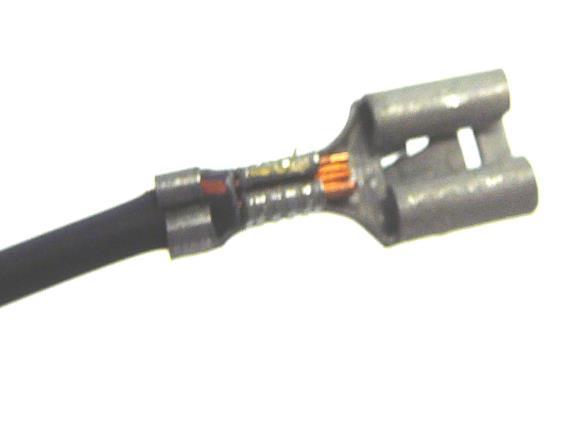
22 The battery B+ circuits of this harness are drawn out in the diagram below. The #915 and #916 wires are connected internally within the fuse block. Battery cables such as the one in the picture below are not included in this kit. We suggest that you install new battery cables and that they are at least 1 gauge in size. 12. Route the light blue/black wire (labeled #922) to the engine oil pressure gauge sender. This wire protrudes from the main fuel injection breakout at the back of the intake manifold. Terminate it with the appropriate terminal from the parts kit and connect it to the sender. 21
 into the mating coil harness located on the passenger side valve cover.")
23 13. Plug the 4 black two pin passenger side injector connectors into their mating injector. #2 cylinder is at the front passenger side of the engine. 14. Plug the wire seven pin passenger side coil connector (labeled PASS COILS) into the mating coil harness located on the passenger side valve cover. 22

 to the engine temperature gauge sender. This wire protrudes from the same harness breakout as the #8 injector connector.")
24 15. Route the green wire (labeled #902) and the black wire (labeled #992) to the A/C compressor. The #902 wire is the PCM controlled A/C compressor clutch activation wire. Use the appropriate terminal from the parts kit to connect this wire to the A/C compressor clutch activation wire located on the A/C compressor. If your compressor clutch requires an external ground connect the #992 to it. The #922 wire is a constant battery ground wire; if you don t need it just tape it back in the harness. 16. Route the light green wire (labeled #921) to the engine temperature gauge sender. This wire protrudes from the same harness breakout as the #8 injector connector. Terminate it with the appropriate terminal from the parts kit and connect it to the sender. 23
 into the mass air flow")
25 17. Plug the black five pin mass air flow/intake air temp sensor connector (labeled MAF/IAT) into the mass air flow sensor. 24

 to the battery post on the starter.")
26 18. Plug the black three pin crankshaft position sensor connector (labeled CKP) into the crankshaft position sensor located on the passenger side of the engine just above and behind the starter. It may be necessary to remove the starter from the engine in order to gain access to this sensor. 19. Route the purple wire (labeled #919) to the S post on the starter. Cut it to length and terminate with the appropriate terminal from the parts kit. Attach to the starter. Route the red wire (labeled #916) to the battery post on the starter. Cut it to length, slide one piece of the heat shrink and terminate with the appropriate terminal from the parts kit. Attach to the starter. 25


27 20. Plug the black four pin passenger side oxygen sensor connector (labeled PASS SIDE OXY) into the passenger side oxygen sensor. Plug the black four pin driver side oxygen sensor connector (labeled DRVR SIDE OXY) into the driver side oxygen sensor. 21. Plug the black seven pin park/neutral connector (labeled PRNDL) into the PRNDL switch located on the driver side of the transmission. 26

 into the vehicle speed sensor")
28 22. Plug the grey 13 pin 4L60E transmission solenoid connector (labeled TRANSMISSION) into the mating connector port located on the passenger side of the transmission just behind the lube level indicator tube. 23. Plug the black two pin vehicle speed sensor connector (labeled VSS) into the vehicle speed sensor located on the passenger side of the tail shaft housing of the transmission. 27
29 Wiring the front of your vehicle: This section of this harness includes wires for the front lighting circuits, horn, wiper/washer, cruise control module and electric cooling fans. This section should be routed over to the driver s side of the steering column and then out to the engine compartment through the firewall. A grommet of the appropriate size is included in the parts kit. Locate where in the firewall you would like the headlight section wires to protrude through and drill a 1 ¼ hole. De-burr the hole, wrap the bare metal edge with electrical tape and then feed the headlight section wires through it and out into the engine compartment. Included in the parts kit and bubble pack are headlight connectors, terminals, park/turn light sockets and several types of zip ties. Use these parts where they are applicable to your harness installation. Route the headlight section wires to the front of the vehicle. Separate the driver s side and passenger s side wires into their own break outs. Loosely zip tie the harness to the driver s side inner fender or route it between the inner and outer fenders. 1. Cruise Control Module The cruise control module connector may need to be routed out through the same grommet used for the Headlight Section wires. If so, do this now and route this connector over to the cruise control module and plug it in. 2. Wiper Motor The wiper motor wires #905, #978, #979 and #976 may need to be routed out through the same grommet used for the Headlight Section wires. If so, do this now and route the wires up to the wiper motor and window washer motor. If your wiper and washer motors require the use a different fire wall hole and grommet please locate it or drill it now. Several grommets are provided in the parts kit. Find one the right size to fit your hole. Connect the wiper and washer motor wires as follows. You will find connectors and terminals in the bubble pack that will fit most wiper motors. If these don t fit your specific application please use some of the heat-shrinkable spade terminals that are also in the bubble pack. a. #905 is the power wire for your wiper and washer motors. This wire will need to be jumped between the wiper and washer motors in some applications. b. #978 is the low speed wire that grounds the low speed circuit of the wiper motor when the wiper switch is in the low speed position. c. #979 is the high speed wire that grounds the high speed circuit of the wiper motor when the wiper switch is in the high speed position. d. #976 is the wash wire that grounds the washer motor when the wiper switch is in the wash position. 28

30 4. Route the driver s side wires #969, #909, #908, #926 and #927 to the driver s side headlights and front park/turn lights. Cut them to length, strip and terminate then connect to their mating components. a. #969 is a ground wire that requires you to splice it between all of the driver s side lighting components. This wire is spliced to the interior ground wire that will be attached under the dash. b. #909 is spliced to reach both driver and passenger side low beam headlights. This wire provides 12 Volts to the low beam headlights when the dimmer switch is in the low beam position. c. #908 is spliced to reach both driver and passenger side high beam headlights. This wire provides 12 volts to the high beam headlights when the dimmer switch is in the high beam position. d. #926 is the driver side turn signal wire that provides 12 Volts when the turn signal lever is in the left hand turn position. e. #927 is spliced to reach both driver and passenger side park lights. This wire provides 12 Volts to the park lights when the headlight switch is in the park light position (usually the first click when pulled out). 5. Route the wire #924 to the horn. Cut it to length, strip and terminate it with the proper terminal from the bubble pack and connect it. If you have dual horns jumper what you cut off as excess between the two horns. This wire provides the relayed 12 Volts that operates the horn with the horn button depressed. Make sure where the horn is mounted it is also receiving a clean ground or if your horn has two terminals on it ground the second terminal. 29
31 6. Route the passenger side wires #969, #909, #908, #925 and #927 to the passenger side headlights and front park/turn lights. Cut them to length, strip and terminate then connect to their mating components. f. #969 is a ground wire that requires you to splice it between all of the driver s side lighting components. This wire is spliced to the interior ground wire that will be attached under the dash. g. #909 is spliced to reach both driver and passenger side low beam headlights. This wire provides 12 Volts to the low beam headlights when the dimmer switch is in the low beam position. h. #908 is spliced to reach both driver and passenger side high beam headlights. This wire provides 12 volts to the high beam headlights when the dimmer switch is in the high beam position. i. #925 is the passenger side turn signal wire that provides 12 Volts when the turn signal lever is in the right hand turn position. j. #927 is spliced to reach both driver and passenger side park lights. This wire provides 12 Volts to the park lights when the headlight switch is in the park light position (usually the first click when pulled out). 7. Route the #998 and #999 wires to your radiator electric cooling fans. These wires provide relayed 12 volts to your cooling fans when the PCM requests them on. They both have their own 40 Amp, type 1, circuit breaker in the fuse block. If your vehicle only requires one of these wires, please use #998. Ground the fans to the radiator support or directly to the battery negative post. 30

32 Wiring the Interior of your Vehicle: This section of your wiring project requires some special attention to routing and attachment of the harness. Separate out the harness breakouts for each switch or component. Group the breakouts together that will be routed to the same section of your dash board. For instance, if your headlight switch, wiper switch and instrument cluster are all mounted in the same section of your dash board then you should route these wires as one group and then separate them out to their mating components. 1. Instrument Panel Section: Connect the wires for your instrument panel as the diagram shown below indicates. If you require a pin out diagram for your instrument cluster because it is a printed circuit board please feel free to contact our tech a. #935 is ignition hot 12 Volts to power your gauges. You need to jumper this wire to each gauge s power terminal. b. #930 is the illumination wire that provides 12 Volts when the headlight switch is in the on position. If you have a dimmable headlight switch this wire will vary in voltage depending on where the dimmer is set. You need to jumper this wire to each gauge s illumination power terminal. c. #922 is the sender wire for your oil pressure gauge. This wire is simply a straight through wire that connects the oil pressure gauge to the oil pressure sender. 31
33 d. #921 is the sender wire for your engine coolant temperature gauge. This wire is simply a straight through wire that connects the engine coolant temperature gauge to the engine coolant temperature sender. e. #969 is the ground wire for your gauges. You need to jumper this wire to each gauge s ground terminal and to each indicator light ground wire. f. #939 is the sender wire for your fuel tank level gauge. This wire is simply a straight through wire that connects the fuel level gauge to the fuel level sender in the fuel tank. g. #936 is the high beam indicator light activation wire. This wire provides 12 Volts to the high beam indicator light when the headlight switch is on and the dimmer switch is in the high beam headlight position. h. #964 is the vehicle speed sensor signal wire for your speedometer. Connect this wire to your digital speedometer signal terminal. i. #923 is the tachometer signal wire. Connect this wire to your tachometer signal terminal. j. #938 is the right turn indicator light activation wire. This wire provides 12 Volts to the right turn indicator light when the turn signal lever is in the right hand turn position. k. #937 is the left turn indicator light activation wire. This wire provides 12 Volts to the left turn indicator light when the turn signal lever is in the left hand turn position. 32

34 2. Headlight Switch Section: Connect the wires to your headlight switch as the diagram indicates. Included the parts kit and bubble pack are terminals and a connector that mate to this type of headlight switch. Use the jaw style crimpers to crimp these terminals onto the wires. Hold the connector up to the headlight switch as it would connect and insert the wires as shown in the diagram. If your headlight switch is different than the one shown in the diagram then look at the wire descriptions and match them to your headlight switch s pin out. a. #927 is the front park lights power wire. b. #929 is the rear tail lights and marker lights power wire. c. #930 is the illumination wire that splices to the gauge section, radio section and accessory section of wires. d. #961 is the dome light activation wire. This wire is grounded by the headlight switch when the knob is turned all the way counter clockwise. e. #907 is the headlight dimmer switch power wire. This wire provides 12 volts to the dimmer switch when the headlight switch is in the second pulled out position. f. #928 is the high amperage headlight switch power wire. This wire is connected internally within the headlight switch to the #907 wire when the headlight switch is the second pulled out position. 33

35 g. #959 is the low amperage headlight switch power wire. This wire is connected internally within the headlight switch to the #927, #929 and #930 wires when the headlight switch is on. 3. Dimmer Switch Section: Use the connector and terminals provided in the bubble pack to make this connection. a. #907 wire is the power into the dimmer switch. b. #909 wire is power out of the dimmer switch to the low beam headlights. c. #908 wire is power out of the dimmer switch to the high beam headlights. 4. Turn Switch Section: Connect the wires for your turn signal switch as the diagram indicates. Included in the parts kit and bubble pack are terminals and a connector that mate to both types of GM steering column mounted turn switch connectors. Use the jaw style crimpers to crimp these terminals onto the wires. a. #963 is the horn relay activation wire. This wire grounds the horn relay when the horn button is depressed. b. #926 is the front left turn signal wire. This wire is spliced to the #937 wire and is provided 12 Volts when the turn lever is in the left hand position. c. #925 is the front right turn signal wire. This wire is spliced to the #938 wire and is provided 12 Volts when the turn lever is in the right hand position. 34

36 d. #951 is the hazard flasher input wire for the hazard switch. This wire is a constant 12 Volt wire. e. #952 is the turn flasher input wire for the turn signal switch. This wire is a switched 12 Volt wire. f. #949 is the right rear turn/brake signal wire. If your vehicle has integrated turn/brake lights in the rear this wire is used to indicate both with one bulb. If your vehicle has separate turn/brake lights in the rear this wire is used to indicate turn only. g. #949 is the left rear turn/brake signal wire. If your vehicle has integrated turn/brake lights in the rear this wire is used to indicate both with one bulb. If your vehicle has separate turn/brake lights in the rear this wire is used to indicate turn only. h. #918 is the brake switch input into the turn signal switch. If your vehicle has integrated turn/brake lights then you must connect this wire to the turn switch as indicated in the diagram. If your vehicle has separate turn/brake lights then do not connect this wire at the turn signal switch. Insulate the end with some tape and zip tie it up out of the way. 5. Column Mounted Ignition Switch Section: Connect the wires for your column mounted ignition switch as the diagram indicates. Included in the parts kit and bubble pack are terminals and a connector that mate to the steering column mounted ignition switch. Use the jaw style crimpers to crimp these terminals onto the wires. 35

37 a. #934 provides battery 12 Volts to the ignition switch. In order for this type of ignition switch to function properly you are required to splice this wire and connect it to both terminals as indicated in the diagram. Use one of the butt connectors from the bubble pack to do this splice. b. #931 is the coil power wire. In order for this type of ignition switch to function properly with this harness you are required to install a jumper wire to go between the #931 and #933 wires. This jumper wire provides the #933 wire 12 Volts from the #931 wire while cranking the engine. c. #933 provides 12 Volts to the wiper, turn and gauge/cruise fuses. This wire also activates the fuel injection relay. d. #932 provides 12 Volts to the window, a/c-heat and radio fuses. e. #919 is the engine crank signal wire that connects to the park/neutral switch and then to the starter if in park or neutral. 6. Dash Mounted Ignition Switch Section: Connect the wires for your column mounted ignition switch as the diagram indicates. Included in the bubble pack are terminals that mate to most dash mounted ignition switch. a. #934 provides battery 12 Volts to the ignition switch. Connect this wire to the battery terminal of your ignition switch. 36

38 b. #931 & #933 wires are must be connected this to the ignition terminal of your ignition switch. #931 provides power to the coil fuse. #933 provides power to the wiper, turn and gauge/cruise fuses. c. #932 wire must be connected to the accessory post of your ignition switch. This wire provides 12 Volts to the window, a/c-heat and radio fuses. d. #919 wire must be connected to the starter/crank post of your ignition switch. This wire is the engine crank signal wire that connects to the park/neutral switch and then to the starter if in park or neutral. 7. Accessory Switch Section: The accessory switch section of this harness provides wires for a cigarette lighter, a/c-heater switch, wiper switch, illumination power and ground. Connect the wires as listed. If your vehicle has an illuminated a/c-heat switch, wiper switch and cigarette lighter use the #969 & #930 wires to power the lighted sockets. a. Connect the wires for your a/c-heater switch as the diagram indicates. #904 wire is fused by the a/c-heat 30 Amp fuse. It provides ignition switched power for your a/c-heater switch. #902 wire is to be connected to your a/c request wire from your a/c-heat switch. If using the OEM switch it is the wire that originally went out to the a/c compressor clutch. When you turn your a/c switch to a/c or defrost this wire tells the PCM that you are requesting the a/c compressor to turn on. If the PCM sees this request as acceptable it then activates the a/c relay on the fuse block. This relay switches 12 Volts to the a/c compressor clutch which engages it. 37
39 Note: Using the PCM to control your a/c compressor brings with it several benefits. The first is the PCM has a built in rpm window that it allows the a/c compressor to operate within. Anything above 4300 rpm the PCM shuts off the a/c compressor. Once the engine rpm returns to below 3900 rpm the a/c compressor is reengaged. Second, the PCM shuts off the a/c compressor if it registers wide open throttle. Once the throttle returns back to 0% the a/c compressor is reengaged. The fans are shut off when the vehicle is travelling above 40mph. Finally, the PCM automatically activates the engine cooling fans when it activates the a/c compressor. b. Connect the cigarette lighter power wire #903 to your cigarette lighter or power port. Most of the time this connection will utilize one of the heat shrinkable bullet connectors from the bubble pack. If you are mounting the cigarette lighter into a non-metallic (non conducting material) be sure to add a ground wire to the bezel. The #903 wire is battery hot 12 Volts. c. Connect the #978, #979 & #976 wires to your wiper switch. Most wiper switches are self grounding into whatever they mount in. If your wiper switch is not self grounding you are required to add another wire to ground the switch. #978 wire is for the low speed of your wiper motor. #979 wire is for the high speed of your wiper motor. #976 wire is for the washer motor. If you find that your wiper system is completely different or you are having issues figuring out how your switch connects, please call our tech Radio Section: The radio section of this harness provides power, ground, amp on, power antenna on and speaker wires. Connect these wires as follows. a. #941 wire provides ignition 12 Volts for your radio to turn on when the ignition key is in the on or accessory position. b. #940 wire provides battery 12 Volts for your radio to retain its radio and equalizer presets. c. #954 wire is for an amplifier activation. If you have an external amplifier connect this wire to the AMP ON wire coming from the radio. If you don t have an external amplifier then cap and zip tie this wire up out of the way because you won t use it. d. #942 wire is for activation of a power antenna. If you have a power antenna connect this wire to the ANT ON wire coming from the radio. If you don t have a power antenna then cap and zip tie this wire up and out of the way because you won t use it. e. #930 wire is to activate the dimming function of your radio s display. Some radios have this feature and some do not. If yours does then connect this to ILLUMINATION wire coming from the radio. If your radio does not have this feature then tape up the wire end and zip tie it out of the way. f. #969 wire is a ground wire for your radio. Connect this wire to the GROUND wire coming from the radio. g. This harness provides four speaker wire sets. Two for the front and two for the rear. They are not printed with labels as to which are which. Use a Volt/Ohm meter to identify which wire set goes where. Connect them to your radio according to its manufactures instructions. 38

. b. The grey wire #973 is the cruise control on/off switch signal (connector pin B).")
40 9. Cruise Switch Section: The cruise switch section of this harness provides power, cruise on/off, resume/accelerate and set/coast wires. Connect these wires as follows. Most late model GM steering columns years already have or can be retrofitted with a cruise control switch. See figure below for the proper connection of these wires to a factory GM cruise control switch part number This harness kit does not include the connector needed because it has been discontinued by Delphi. a. The pink wire #957 is power (connector pin A). b. The grey wire #973 is the cruise control on/off switch signal (connector pin B). c. The blue wire #974 is the cruise control set/coast switch signal (connector pin D). d. The grey/black wire #975 is the cruise control resume/accelerate switch signal (connector pin C). 10. Brake Switch Section: Provided with the parts kit is a four pin brake switch. Connect the brake switch wires according to the diagram to the right. Use some of the heat shrinkable spade connectors provided in the bubble pack. This switch must be mounted so that the plunger is pushed into the switch when the brake pedal is at rest. 39

41 11. Driver Door Section: Route these wires over to the driver s door. Connect as follows. a. #910 wire is battery 12 Volts to power an electric lock switch. b. #913 wire is accessory and ignition hot 12 Volts to power an electric window switch. c. #961 wire is spliced with the rest of the dome light ground circuits. This wire needs to be connected to a grounding door jamb switch. 12. Passenger Door Section: Route these wires over to the driver s door. Connect as follows. a. #912 wire is battery 12 Volts to power an electric lock switch. b. #911 wire is accessory and ignition hot 12 Volts to power an electric window switch. c. #961 wire is spliced with the rest of the dome light ground circuits. This wire needs to be connected to a grounding door jamb switch. 13. Courtesy Lights Section: Connect these two wires to all of the interior courtesy lights. See the diagram below for more information. a. #961 wire is spliced with the rest of the dome light ground circuits. Connect this to the ground side of your courtesy lights. b. #989 wire is battery 12 Volts to power all of the interior and courtesy lights. It is spliced with the dome light power wire #


42 14. Ground #3: Connect this #969 wire to a clean ground source under the dash. Use the appropriate heat shrinkable ring terminal from the bubble pack to make this connection. This wire splices to the grounds shown in the diagram below. 15. DLC: This harness includes a diagnostic link connector, service engine soon light and mounting bracket for both. Find a suitable place to mount this connector and mount it. Make sure it is accessible for future use. 41
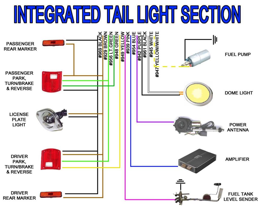
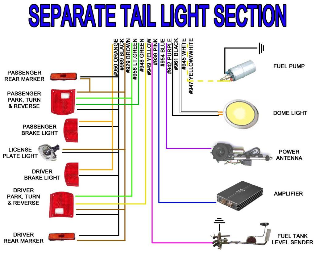
43 Wiring the rear of your vehicle: This section of this harness includes wires for the rear lighting circuits, fuel tank sending unit, electric fuel pump, dome light, power antenna and amplifier. The diagrams below indicate both ways to connect the tail section of this harness. If your vehicle s turn/brake lights are integrated you will follow the first diagram. If your vehicle s turn/brake lights are separate you will follow the second diagram. Both are on the next page. Use the heat shrinkable butt splices to make these connections. a. #969 wire is for grounding the rear lighting section. This wire is spliced to two wires. Use one for the driver side and the other for the passenger side. Jumper the wire to all of the ground terminals of your tail section lighting. If you don t have ground terminals on your bulb sockets because they are self grounding we suggest that you connect this ground wire to somewhere near the tail light housings. b. #929 wire is to power the tail lights, marker lights and license plate light. This wire is spliced to two wires. Use one for the driver side and the other for the passenger side. Jumper the wire to all of the power terminals of your tail, marker and license plate lights. c. #956 wire is to power your reverse lights. Jumper this wire to the power terminals of your reverse lights. d. #948 wire is to power your passenger rear turn/brake light if you have integrated lights. If your lights are separate only connect this wire to your turn signal light power terminal. e. #949 wire is to power your driver rear turn/brake light if you have integrated lights. If your lights are separate only connect this wire to your turn signal light power terminal. f. #950 wire is to power your separate brake lights or for a third brake light. Only connect this wire to your brake lights if they are a separate bulb filament from anything else. g. #939 wire must be connected to your fuel sender signal terminal. Make sure the fuel sender has a ground wire that is grounded to the vehicle s chassis or body. h. #954 wire is for activation of an external radio amplifier. The amplifier should have a terminal labeled REMOTE or AMP ON. If you don t have an external radio amplifier cap and zip tie this wire up and out of the way. i. #942 wire is for activation of a powered antenna. This wire signals the antenna to extend. You will need to run your own power and ground wires here. If you don t have a powered antenna cap and zip tie this wire up and out of the way. j. #961 wire is to ground your dome light and any other light you want to turn on when the door is open or the headlight switch is commanding it on. k. #945 wire is to power your dome light and any other light you want to turn on when the door is open or the headlight switch is commanding it on. l. #947 wire is to power your electric fuel pump. Make sure to add a ground wire of the same gauge and to a clean ground source. 42
44 43
45 TESTING THE SYSTEM Use a small (10 amp or less) battery charger to power up the vehicle for the first time to test the circuits. If there is a problem anywhere, the battery charger's low amperage and internal circuit breaker will provide circuit protection. a. Make sure the Negative Battery cable is connected to the frame or engine, and make sure there is a ground between the engine and frame. The Negative Battery cable should still be disconnected from the Battery. b. Connect the Battery Positive cable to the Positive side of the Battery and also make sure this cable is connected to the B+ side of the Starter Solenoid and is connected. c. Connect the Battery Charger's NEGATIVE cable to the automobile chassis, engine block or to the disconnected Negative Battery cable. Do NOT connect the Battery Charger's NEGATIVE cable to the Battery. d. Connect the Battery Charger's POSITIVE cable to the automobile's positive battery terminal lug. e. INDIVIDUALLY turn on each light, ignition, wiper circuit, etc. and check for proper operation. Note: The turn signals will not flash properly if you do not have both the front and rear bulbs installed and connected. f. After all circuits have been checked, disconnect the battery charger and attach the vehicles battery cables to the battery. 44
46 WIRE INDEX: HEADLIGHT SECTION COLOR GAUGE CIRCUIT FUNCTION ORIGIN GREEN 12 #998 FAN #1 RELAY POWER TO COOLING FAN #1 FUSE BLOCK BLUE 12 #999 FAN #2 RELAY POWER TO COOLING FAN #2 FUSE BLOCK BLACK 14 #969 DRIVER SIDE LIGHTING GROUND WIRE INTERIOR GROUND BLACK 14 #969 PASSENGER SIDE LIGHTING GROUND WIRE INTERIOR GROUND BROWN 18 #927 DRIVER SIDE PARK LIGHT POWER HEADLIGHT SWITCH BROWN 18 #927 PASSENGER SIDE PARK LIGHT POWER HEADLIGHT SWITCH TAN 16 #909 DRIVER SIDE LOW BEAM HEADLIGHT POWER DIMMER SWITCH TAN 16 #909 PASSENGER SIDE LOW BEAM HEADLIGHT POWER DIMMER SWITCH LT.GREEN 16 #908 DRIVER SIDE HIGH BEAM HEADLIGHT POWER DIMMER SWITCH LT.GREEN 16 #908 PASSENGER SIDE HIGH BEAM HEADLIGHT POWER DIMMER SWITCH LT.BLUE 18 #926 DRIVER SIDE (LF) TURN SIGNAL POWER TURN SWITCH BLUE 18 #925 PASSENGER (RF) TURN SIGNAL POWER TURN SWITCH GREEN 14 #924 HORN POWER FUSE BLOCK WIPER MOTOR SECTION COLOR GAUGE CIRCUIT FUNCTION ORIGIN YELLOW 16 #905 WIPER MOTOR POWER FUSEBLOCK LT.BLUE 16 #978 WIPER MOTOR LOW SPEED WIPER SWITCH BLUE 16 #979 WIPER MOTOR HIGH SPEED WIPER SWITCH BLACK 18 #976 WASHER MOTOR WASH WIPER SWITCH INSTRUMENT PANEL SECTION COLOR GAUGE CIRCUIT FUNCTION ORIGIN RED/WHITE 18 #935 GAUGE POWER FUSE BLOCK BLACK 18 #969 GAUGE/INDICATOR GROUND INTERIOR GROUND BROWN 18 #930 GAUGE ILLUMINATION HEADLIGHT SWITCH BLUE 20 #938 RIGHT TURN INDICATOR POWER TURN SWITCH PINK 18 #939 FUEL GAUGE SENDER WIRE FUEL TANK SENDER LT.GRN/BLK 18 #921 TEMPERATURE GAUGE SENDER WIRE TEMP SENDER GRN/WHITE 20 #964 SPEEDOMETER GAUGE SENDER WIRE PCM LT.BLUE 20 #937 LEFT TURN INDICATOR POWER TURN SWITCH LT.GREEN 20 #936 HIGH BEAM INDICATOR POWER DIMMER SWITCH WHITE 18 #923 TACHOMETER GAUGE SENDER WIRE PCM LT.BLU/BLK 18 #922 OIL PRESSURE GAUGE SENDER WIRE OIL PRESSURE SENDER 45
47 HEADLIGHT SWITCH SECTION COLOR GAUGE CIRCUIT FUNCTION ORIGIN RED/BLACK 14 #928 HEADLIGHT SWITCH POWER FUSE BLOCK ORANGE 14 #959 HEADLIGHT SWITCH POWER FUSE BLOCK BROWN 16 #927 FRONT PARK LIGHT POWER HEADLIGHT SWITCH BROWN 16 #929 TAIL LIGHT POWER HEADLIGHT SWITCH BROWN 16 #930 DASH PANEL ILLUMINATION POWER HEADLIGHT SWITCH BLUE/YELLO HEADLIGHT 14 #907 DIMMER SWITCH POWER W SWITCH BLACK 18 #961 DOME/COURTESY LIGHT GROUND HEADLIGHT SWITCH IGNITION SWITCH SECTION COLOR GAUGE CIRCUIT FUNCTION ORIGIN BROWN 12 #932 ACCESSORY POWER FUSEBLOCK RED 10 #934 BATTERY POWER TO IGNITION SWITCH FUSEBLOCK PINK 14 #931 COIL POWER FUSEBLOCK ORANGE 12 #933 IGNITION POWER FUSEBLOCK PURPLE 12 #919 START SIGNAL TO PRNDL SWITCH IGNITION SWITCH TURN SWITCH SECTION COLOR GAUGE CIRCUIT FUNCTION ORIGIN LT.BLUE 18 #926 DRIVER (LF) TURN SIGNAL POWER TURN SWITCH BLUE 18 #925 PASSENGER (RF) TURN SIGNAL POWER TURN SWITCH WHITE 16 #918 BRAKE LIGHT POWER INTO SWITCH BRAKE SWITCH GREEN 16 #948 PASSENGER (RR) TURN SIGNAL POWER TURN SWITCH YELLOW 16 #949 DRIVER (LR) TURN SIGNAL POWER TURN SWITCH BROWN 16 #951 EMERGENCY FLASHER POWER TO SWITCH EMERGENCY FLASHER PURPLE 16 #952 TURN FLASHER POWER TO SWITCH TURN FLASHER BLACK 18 #963 HORN RELAY ACTIVATION HORN RELAY CRUISE SWITCH SECTION COLOR GAUGE CIRCUIT FUNCTION ORIGIN PINK 20 #957 CRUISE CONTROL SWITCH POWER FUSEBLOCK GREY 20 #973 CRUISE CONTROL SWITCH ON/OFF COMMAND CRUISE MODULE BLUE 20 #974 CRUISE CONTROL SWITCH SET/COAST COMMAND CRUISE MODULE GREY/BLACK 20 #975 CRUISE CONTROL SWITCH RESUME/ACCEL COMMAND CRUISE MODULE 46
48 DIMMER SWITCH SECTION COLOR GAUGE CIRCUIT FUNCTION ORIGIN BLUE/YELLO HEADLIGHT 14 #907 DIMMER SWITCH POWER W SWITCH TAN 16 #909 LOW BEAM HEADLIGHT POWER DIMMER SWITCH LT. GREEN 16 #908 HIGH BEAM HEADLIGHT POWER DIMMER SWITCH TURN SWITCH SECTION COLOR GAUGE CIRCUIT FUNCTION ORIGIN BLACK/WHIT E 14 #904 A/C-HEATER SWITCH POWER FUSEBLOCK TAN 14 #903 CIGARETTE LIGHT POWER FUSEBLOCK GREEN/WHI TE 20 #902 A/C COMPRESSOR REQUEST PCM LT.BLUE 16 #978 WIPER MOTOR LOW SPEED GROUND WIRE WIPER SWITCH BLACK 18 #976 WASHER MOTOR GROUND WIRE WIPER SWITCH BLUE 16 #979 WIPER MOTOR HIGH SPEED GROUND WIRE WIPER SWITCH BROWN 18 #930 ACCESSORY SECTION SWITCH ILLUMINATION HEADLIGHT POWER SWITCH BLACK 18 #969 ACCESSORY SECTION SWITCH ILLUMINATION GROUND INTERIOR GROUND RADIO SECTION COLOR GAUGE CIRCUIT FUNCTION ORIGIN RED 18 #941 RADIO IGNITION POWER FUSEBLOCK YELLOW 18 #940 RADIO BATTERY POWER FUSEBLOCK BLUE 20 #954 AMPLIFIER REMOTE WIRE RADIO PURPLE 20 #942 POWER ANTENNA REMOTE WIRE RADIO BROWN 18 #930 RADIO ILLUMINATION WIRE HEADLIGHT SWITCH BLACK 18 #969 RADIO GROUND INTERIOR GROUND SPEAKER 18 4 SETS FRONT AND REAR SPEAKER WIRES RADIO BRAKE SWITCH SECTION COLOR GAUGE CIRCUIT FUNCTION ORIGIN PINK 18 #984 CRUISE RELEASE SWITCH POWER FUSEBLOCK ORANGE 16 #917 BRAKE SWITCH POWER FUSEBLOCK WHITE 16 #918 BRAKE SWITCH TO BRAKE LIGHTS BRAKE SWITCH PURPLE 18 #900 CRUISE RELEASE SWITCH TO CRUISE MODULE BRAKE SWITCH 47
49 DRIVER DOOR SECTION COLOR GAUGE CIRCUIT FUNCTION ORIGIN YELLOW/BL K 14 #910 ELECTRIC DOOR LOCK SWITCH POWER FUSEBLOCK YELLOW 14 #913 ELECTRIC WINDOW SWITCH POWER FUSEBLOCK BLACK 18 #961 DOME/COURTESY LIGHT GROUND HEADLIGHT SWITCH PASSENGER DOOR SECTION COLOR GAUGE CIRCUIT FUNCTION ORIGIN YELLOW/BL K 14 #912 ELECTRIC DOOR LOCK SWITCH POWER FUSEBLOCK YELLOW 14 #911 ELECTRIC WINDOW SWITCH POWER FUSEBLOCK BLACK 18 #961 DOME/COURTESY LIGHT GROUND HEADLIGHT SWITCH COURTESY LIGHT SECTION COLOR GAUGE CIRCUIT FUNCTION ORIGIN BLACK 18 #961 DOME/COURTESY LIGHT GROUND HEADLIGHT SWITCH WHITE 18 #989 DOME/COURTESY LIGHT POWER FUSEBLOCK TAIL SECTION COLOR GAUGE CIRCUIT FUNCTION ORIGIN YELLOW/W HT 14 #947 FUEL PUMP POWER FUSEBLOCK WHITE 18 #945 DOME/COURTESY LIGHT POWER FUSEBLOCK BLACK 16 #969 DRIVER SIDE LIGHTING GROUND INTERIOR GROUND BLACK 16 #969 PASSENGER SIDE LIGHTING GROUND INTERIOR GROUND BROWN 18 #929 DRIVER SIDE TAIL LIGHT POWER HEADLIGHT SWITCH BROWN 18 #929 PASSENGER SIDE TAIL LIGHT POWER HEADLIGHT SWITCH ORANGE 18 #950 THIRD BRAKE LIGHT POWER BRAKE SWITCH LT.GREEN 18 #956 REVERSE LIGHT POWER PRNDL SWITCH GREEN 16 #948 PASSENGER (RR) TURN/BRAKE POWER TURN SWITCH YELLOW 16 #949 DRIVER (LR) TURN/BRAKE POWER TURN SWITCH PURPLE 20 #942 POWER ANTENNA REMOTE WIRE RADIO BLUE 20 #954 EXTERNAL AMPLIFIER REMOTE WIRE RADIO PINK 18 #939 FUEL SENDER SIGNAL WIRE FUEL SENDER 48
50 49
51 50
52 51
Trail Rocker Installation Instructions
 Trail Rocker Installation Instructions Manual #90580 For Installing Painless Part Numbers: 57000 and 57001 Painless Performance Products recommends you, the installer, read this installation manual from
Trail Rocker Installation Instructions
 Trail Rocker Installation Instructions Manual #90581 For Installing Painless Part Numbers: 57002 Painless Performance Products recommends you, the installer, read this installation manual from front to
Wire Harness Installation Manual # Part # UP Gen IV 4.8L - 6.2L W/4L65E
 Wire Harness Installation Manual #90575 For Installing: Part # 60526 2007-UP Gen IV 4.8L - 6.2L W/4L65E Perfect Performance Products, LLC Painless Performance Products Division 2501 Ludelle Street Fort
Installation Instructions. Part #65100
 Installation Instructions Part #65100 Perfect Performance Products, LLC Painless Performance Products Division 2501 Ludelle Street Fort Worth, TX 76105-1036 800-423-9696 phone 817-244-4024 fax Web Site:
Track Rocker Installation Instructions
 Track Rocker Installation Instructions For Installing Painless Part Numbers: 58103: 8-Switch Customizable Track Rocker Switch Panel w/ Flanged Mount 58106: 6-Switch Customizable Track Rocker Switch Panel
Trail Rocker Installation
 Trail Rocker Installation Instructions Customizable Trail Rocker Control System For Installing Painless Part Number: 57100 Manual #90616 Painless Performance Products recommends you, the installer, read
Trail Rocker Installation
 Trail Rocker Installation Instructions 4, 6, or 8 - Switch Customizable Trail Rocker Switch Panel w/ Flanged Mount For Installing Painless Part Number: 57103, 57106, & 57109 Manual #90636 Painless Performance
Off-Road Switch Panel Installation Instructions
 Off-Road Switch Panel Installation Instructions 50330: Off-road 4 Toggle switches/dash Mount w/keyed Ignition Switch 50332: Off-road 6 Toggle switches/dash Mount w/keyed Ignition Switch Painless Performance
Wire Harness Installation Instructions
 Wire Harness Installation Instructions For Installing: Part #50001 Race Car Kit/8 Circuit Part #50201 8 Switch Dash Mounted Panel Part #50202 8 Switch Roll Bar Mounted Panel Manual #90502 Painless Performance
Trail Rocker Installation Instructions
 Trail Rocker Installation Instructions Trail Rocker - Genesis Bracket For Installing Painless Part Number: 57200 Manual # 90591 To be used with Painless Kit # s: 57000-57005 Painless Performance Products
Installation Instructions
 Installation Instructions Part #40120 Perfect Performance Products, LLC Painless Performance Products Division 2501 Ludelle Street Fort Worth, TX 76105-1036 800-423-9696 phone 817-244-4024 fax Web Site:
jegs.com
 Contents Wiring Harness w/ Fuse Panel Installation Instructions Turn Signal Plug w/ Terminals 2 Headlight Plugs 3/4 Grommet 10 ¼ Terminals 4 Ring Terminals 10 Wire Ties Fusible Link 2 Screws & Nuts 2 Plastic
Installation Instructions. Manual # For Installing: Part # Painless Gauge Controller
 Installation Instructions Manual #90579 For Installing: Part #60650- Painless Gauge Controller Perfect Performance Products, LLC Painless Performance Products Division 2501 Ludelle Street Fort Worth, TX
30140 F5 Dual Fan Controller
 30140 F5 Dual Fan Controller 1 2501 Ludelle Street Fort Worth, Texas 76105 817-244-6212 Phone 817-244-4024 Fax 888-350-6588 Sales 800-423-9696 Tech E-mail: painless@painlessperformance.com Web: www.painlessperformance.com
Track Rocker Installation Instructions
 Track Rocker Installation Instructions Customizable Track Rocker Control System For Installing Painless Part Number: 58100 Track Rocker Relay Center Manual #90641 Painless Performance Products recommends
Part # GM LS2, 3 & 7-95mm Throttle Body
 Part # 65303 2006-2011 GM LS2, 3 & 7-95mm Throttle Body Perfect Performance Products, LLC 2501 Ludelle St. Fort Worth, Texas 76105 (800) 423-9696 1 We are always concerned about any corrections or improvements
Vortec Drive by Cable Electronic Fuel Injection Wiring Harness (P/N HAR-1018) HAR-1018
 HAR-1018") 1998 2002 Vortec Drive by Cable Electronic Fuel Injection Wiring Harness (P/N HAR-1018) HAR-1018 PERFORMANCE SYSTEMS INTEGRATION 170 Oberlin Ave N Suite 13 Lakewood NJ 08701-4548 Ph: 732-444-3277 Email:
1998 2002 Vortec Drive by Cable Electronic Fuel Injection Wiring Harness (P/N HAR-1018) HAR-1018 PERFORMANCE SYSTEMS INTEGRATION 170 Oberlin Ave N Suite 13 Lakewood NJ 08701-4548 Ph: 732-444-3277 Email:
PERFECT HI-VELOCITY 62MM THROTTLE BODY
 PERFECT HI-VELOCITY 62MM THROTTLE BODY Installation Instructions Part # 65300 1991-1998 Jeep 4.0L Engines OR All Jeep 4.0L Engines in Cherokee, Grand Cherokee and Wrangler 1991-2005 w/4 wire IAC ONLY.
'05- 'Current LS2/LS3 Drive by Cable Electronic Fuel Injection Wiring Harness HAR-1058
 '05- 'Current LS2/LS3 Drive by Cable Electronic Fuel Injection Wiring Harness HAR-1058 PERFORMANCE SYSTEMS INTEGRATION 170 Oberlin Ave N Suite 13 Lakewood NJ 08701-4548 Ph: 732-444-3277 Email: INFO@PSIConversion.com
CLASSIC UPDATE WIRING KIT
 by Randy Irwin 1955-57 CLASSIC UPDATE WIRING KIT Randy Irwin - Technical Writer Randy has been involved in the Chevy parts business for over 25 years. He is a wizard at creating, making and modifying custom
INSTRUCTIONS. 20 Circuit Wiring Kit Instructions October 2009, Speedway Motors, Inc.
 1 MAIN FUSE PANEL The main fuse panel harness s designed to be mounted under the dash a the firewall in an area close to the steering column. The enclosed representation of the main dash harness shows
PRXB EXHAUST BRAKE MAXIMUM EXHAUST FLOW DESIGN
 MAXIMUM EXHAUST FLOW DESIGN PRXB EXHAUST BRAKE C44072/C44073/C44074/C44075/C44076 APPLICATION: 994-2002 DODGE RAM TRUCKS W/5.9L CUMMINS DIESEL ENGINES WITH MANUAL & AUTOMATIC TRANSMISSIONS STOCK DODGE
1963 GEN IV SUREFIT VINTAGE AIR CONDITIONING INSTALLATION
 by Randy Irwin 1963 GEN IV SUREFIT VINTAGE AIR CONDITIONING INSTALLATION Randy Irwin - Technical Writer Randy has been involved in the Chevy parts business for over 30 years. He is a wizard at creating,
LSx Harness Installation. lsxeverything.com #BecauseYouShould
 LSx Harness Installation lsxeverything.com #BecauseYouShould Table of Contents Slide 1 Introduction Page Slide 2 Table of Contents Slide 3 Starting Instructions Slide 4 Power Connections Slide 5 Ground
Wire Harness Installation Instructions Manual #90563
 Wire Harness Installation Instructions Manual #90563 For Installing: #10113 Direct Fit 1966-1977 Bronco Harness 28 Circuit w/switches Perfect Performance Products, LLC Painless Performance Products Division
BMW 2002 M42 Swap Notes-THIS IS NOT FINISHED
 BMW 2002 M42 Swap Notes-THIS IS NOT FINISHED This document is to help those that want to install an m42 into a BMW 2002. It is based around an e30 engine, trans, and wiring. You can use the e36 block/head/wiring
Manual P/N Copyright Third Edition June 21, 2005
 P/N 60212, 60213, 60214 & 60215 1996-99 GM VORTEC WIRE HARNESS INSTALLATION INSTRUCTIONS Manual P/N 90524 Copyright 2003 Third Edition June 21, 2005 PAINLESS PERFORMANCE PRODUCTS 2501 Ludelle Street, Fort
GM VORTEC Drive by Wire Electronic Fuel Injection Wiring Harness HAR-1014
 GM VORTEC Drive by Wire Electronic Fuel Injection Wiring Harness HAR-1014 PERFORMANCE SYSTEMS INTEGRATION 170 Oberlin Ave N Suite 13 Lakewood NJ 08701-4548 Ph: 732-444-3277 Email: INFO@PSIConversion.com
Perfect Performance Products, LLC Painless Performance Products Division 2501 Ludelle St. Fort Worth, Texas (800)
") PERFECT HI-VELOCITY 68MM THROTTLE BODY Installation Instructions Part # 65301 1991-1998 Jeep 4.0L Engines w/perfect Engine Management System P/N 65140, 65141 OR All Jeep 4.0L Engines in Cherokee, Grand
PERFECT HI-VELOCITY 68MM THROTTLE BODY Installation Instructions Part # 65301 1991-1998 Jeep 4.0L Engines w/perfect Engine Management System P/N 65140, 65141 OR All Jeep 4.0L Engines in Cherokee, Grand
P/N & GM LS1 w/mechanical (cable) THROTTLE BODY FUEL INJECTION WIRE HARNESS INSTALLATION INSTRUCTIONS
 THROTTLE BODY FUEL INJECTION WIRE HARNESS INSTALLATION INSTRUCTIONS") P/N 60508 & 60509 1997-0 GM LS1 w/mechanical (cable) THROTTLE BODY FUEL INJECTION WIRE HARNESS INSTALLATION INSTRUCTIONS Manual P/N 9050 Painless Performance Products, LLC 501 Ludelle Street Fort Worth,
P/N 60508 & 60509 1997-0 GM LS1 w/mechanical (cable) THROTTLE BODY FUEL INJECTION WIRE HARNESS INSTALLATION INSTRUCTIONS Manual P/N 9050 Painless Performance Products, LLC 501 Ludelle Street Fort Worth,
30140 &30142 F5 Dual Fan Controller
 2501 Ludelle Street Fort Worth, Texas 76105 817-244-6212 Phone 817-244-4024 Fax 888-350-6588 Sales 800-423-9696 Tech E-mail: painless@painlessperformance.com Web: www.painlessperformance.com 30140 &30142
Perfect Performance Products, LLC Painless Performance Products Division 2501 Ludelle St. Fort Worth, Texas (800)
") PERFECT HI-VELOCITY 62MM THROTTLE BODY Installation Instructions Part # 65302 2005-2006 Jeep 4.0L All Jeep 4.0L Engines in Cherokee, Grand Cherokee, Wrangler and Rubicon. Perfect Performance Products,
PERFECT HI-VELOCITY 62MM THROTTLE BODY Installation Instructions Part # 65302 2005-2006 Jeep 4.0L All Jeep 4.0L Engines in Cherokee, Grand Cherokee, Wrangler and Rubicon. Perfect Performance Products,
Installation Instructions For 50330, 50331, 50332, and Off Road Switch Panels
 Installation Instructions For 50330, 50331, 50332, and 50333 Off Road Switch Panels 2501 Ludelle Street Fort Worth, Texas 76105 817-244-6212 Phone 817-244-4024 Fax 888-350-6588 Sales 800-423-9696 Tech
PERFORMANCE SYSTEMS INTEGRATION
 2006 Current GEN IV LSX/Vortec 4.8, 5.3, 6.0, 6.2, 7.0 Drive by Wire (58X) Electronic Fuel Injection Wiring Harness w/ Manual or Non- Electronic Automatic Transmission HAR-10 (See Below) (P/N HAR- 1035,
PRXB EXHAUST BRAKE HIGH PERFORMANCE
 HIGH PERFORMANCE PRXB EXHAUST BRAKE C44059, C4406, C44063, C44065 APPLICATION 994-2002 DODGE RAM AUTOMATIC TRUCKS EQUIPPED WITH 47RE TRANSMISSIONS WITH 5.9L, 24 VALVE CUMMINS DIESEL ENGINES GETTING STARTED
Wire Harness Installation Instructions Manual #90576 For Installing:
 Wire Harness Installation Instructions Manual #90576 For Installing: #20112 Direct Fit Camaro Harness 1970-73 #20113 Direct Fit Camaro Harness 1974-77 #20114 Direct Fit Camaro Harness 1978-81 All 26 Circuit
VORTEC Drive by Wire Electronic Fuel Injection Wiring Harness HAR-1085
 2001 2002 VORTEC Drive by Wire Electronic Fuel Injection Wiring Harness HAR-1085 PERFORMANCE SYSTEMS INTEGRATION 170 Oberlin Ave N Suite 13 Lakewood NJ 08701-4548 Ph: 732-444-3277 Email: INFO@PSIConversion.com
PIN BULKHEAD CONNECTOR KIT
 2501 Ludelle Street Fort Worth, Texas 76105 817-244-6212 Phone 817-244-4024 Fax 888-350-6588 Sales 800-423-9696 Tech E-mail: painless@painlessperformance.com Web: www.painlessperformance.com 40130 22 PIN
DASH/MAIN HARNESS. NOTE: wires 400 & 401, must be twisted together.
 Electric Speedo Ground 151 Turn Flasher 16A 4 150 8A, Cluster Connections 31 33 30 35 151 (electric speedo) 402 401 NOTE: wires 400 & 401, must be twisted together. 156D, E Panel Dimmer 8A 9, C 2D Headlight
SUM EFI Wiring Harness for GM LT-1/LT-4 Engine INSTALLATION INSTRUCTIONS
 SUM-890121 EFI Wiring Harness for GM LT-1/LT-4 Engine INSTALLATION INSTRUCTIONS INTRODUCTION This harness is designed for GM 1992-97 LT1/LT4 fuel injected engines. Even with minimal electrical experience,
P/N & /1995 GM LT1 FUEL INJECTION WIRE HARNESS INSTALLATION INSTRUCTIONS
 P/N 60502 & 60505 1994/1995 GM LT1 FUEL INJECTION WIRE HARNESS INSTALLATION INSTRUCTIONS Manual P/N 90517 Copyright May 2002 PAINLESS PERFORMANCE PRODUCTS 2501 Ludelle Street - Fort Worth, Texas 76105-1036
P/N & GM LS1 FUEL INJECTION WIRE P/N & GM LS1 FUEL INJECTION WIRE HARNESS INSTALLATION INSTRUCTIONS
 P/N 60506 & 60507 1997-98 GM LS1 FUEL INJECTION WIRE HARNESS INSTALLATION INSTRUCTIONS P/N 60508 & 60509 1999-0 GM LS1 FUEL INJECTION WIRE HARNESS INSTALLATION INSTRUCTIONS Manual P/N 9050 Seventh Edition
C FORD F250 / F L POWERSTROKE DIESEL WITH AUTOMATIC TRANSMISSIONS ONLY
 EXHAUST BRAKES C40019 1999-2003 FORD F250 / F350 7.3L POWERSTROKE DIESEL WITH AUTOMATIC TRANSMISSIONS ONLY Getting Started Thank you and congratulations on your purchase of a Pacbrake exhaust retarder.
SUM EFI Wiring Harness for GM LS1 Engine INSTALLATION INSTRUCTIONS
 SUM-890122 EFI Wiring Harness for GM LS1 Engine INSTALLATION INSTRUCTIONS 1 INTRODUCTION This harness is designed for GM 1997-2002 LS1 fuel injected engines utilizing a mechanical throttle body and throttle
90558 Installation Manual For # Cummins 5.9L Common Rail Diesel
 2501 Ludelle Street Fort Worth, Texas 76105 817-244-6212 Phone 817-244-4024 Fax 888-350-6588 Sales 800-423-9696 Tech E-mail: painless@painlessperformance.com Web: www.painlessperformance.com 90558 Installation
Zoom and Print Options
 Vehicle» Engine, Cooling and Exhaust» Engine» Service and Repair» Removal and Replacement» Engine Replacement Engine Replacement ^ Tools Required - J 38185 Hose Clamp Pliers Removal Procedure 1. Remove
40A A 40B. Horn Relay Connector. Brake Switch. Third Brake Light. Brake Switch. Brake Switch. Wires. page 3. Rear Body Feed Wires.
 Fuse Box Connections (viewed from underside) 4D 4C 4D 0 50 300 4C 43 7 39 3 6 4 93 A 2G 2F 2E 2D 2C 2B 2G 2F 2E 40 69A 2 1 5 27 69A 3A B 40A,B 11A,B 40A 156 Dimmer Dome Feed page 2 Horn Relay 2D 2 29 40B
Rear Body 40D 156A 24 17A 151 3D. 8A,8B,8C under hood light. Horn Relay 91
 fuse box as viewed from the wire entry side Mating connector is plugged into Power Accessory connector 40D Rear Body 19 18 9B 30 LH Courtesy Light 40A,D 4D, 43 156B,C 16 16A 4C 3D 3C 16A 3G 4B 3G 116 4A&130
PIMP Ford 5.0 Harness Installation Manual. Part Number: PM-75
 PIMP Ford 5.0 Harness Installation Manual Part Number: PM-75 Ron Francis Wiring 200 Keystone Rd Suite 1 Chester, PA 19013 800-292-1940 www.ronfrancis.com Pre-Installation Notes: This system is designed
Instrument Cluster 30 33B 39B A B C D E F E F G H J. Connector. Circuit Branch #4. Circuit Branch #5. Circuit. Branch #6 150A. Ground.
 16 4D, 43 4B 4A & 130 100 50 39A,B,C 300 4C 4B 4C 107 3C 3D 3C 3G 3B 3F 3A 16A 3G 116 104 93 3B 3D 2E 16A 2C 2D 2B 2A 44 40 27A 40B 115 27 40A,C,E 8A,B,C Mating is plugged into accessory connector Power
INSTRUCTIONS Circuit Wiring Kit Instructions _2017. Fuse Box Connections. (viewed from underside) 2018, Speedway Motors, Inc.
 2018, Speedway Motors, Inc.") Fuse Box Connections (viewed from underside) 4D 4C 100 50 300 4D 4C 4B 4A 43 107 39 103 3B 2G 104 93 2F 2E 2D 2C 2B 40 69A 102 101 105 2G 2F 2E 3A A 2A B 40A,B 27 69A 106 201, Speedway Motors, Inc. 1 Fuse
Fuse Box Connections (viewed from underside) 4D 4C 100 50 300 4D 4C 4B 4A 43 107 39 103 3B 2G 104 93 2F 2E 2D 2C 2B 40 69A 102 101 105 2G 2F 2E 3A A 2A B 40A,B 27 69A 106 201, Speedway Motors, Inc. 1 Fuse
WIRE HARNESS INSTALLATION INSTRUCTIONS
 WIRE HARNESS INSTALLATION INSTRUCTIONS For Installing: #10206 Classic Plus Customizable GM Pickup Chassis Harness 1967-72 28 Circuit Manual #90510 PERFECT PERFORMANCE PRODUCTS, LLC Painless Performance
Wire Harness Installation Instructions For Installing:
 Wire Harness Installation Instructions For Installing: #20106 Classic Plus Customizable Tri-Five Chevy Harness 28 Circuit #20107 Classic Customizable Tri-Five Chevy Harness 21 Circuit Manual #90553 Painless
ISIS Power Manual and Installation Guide Race Car Replicas- Superlite Coupe
 ISIS Power Manual and Installation Guide Race Car Replicas- Superlite Coupe Table of Contents Overview... 2 System Details... 3 Kit Includes... 3 Technical Specifications... 3 Harness Descriptions... 4
Part Number: TDZ-75SD / BRONCO-75SD
 Ford 5.0 EFI Harness Installation Manual For Classic Fords & Mustangs and Early Broncos Part Number: TDZ-75SD / BRONCO-75SD Ron Francis Wiring & The Detail Zone 200 Keystone Rd. Chester, PA 19013 800-292-1940
For Installing Harness Number: Manual #90627
 Wire Harness Installation Instructions For Installing Harness Number: 20205: 27 Circuit 1973-1987 GM Truck Manual #90627 Painless Performance Products recommends you, the installer, read this installation
HOWELL INSTALLATION MANUAL. Tuned Port Or LT-1 Fuel Injection Harness ( )
") HOWELL ENGINE DEVELOPMENTS, INC. FUEL INJECTION APPLICATIONS INSTALLATION MANUAL Tuned Port Or LT-1 Fuel Injection Harness (1985-1992) Howell Engine Developments, Inc. 6201 Industrial Way Marine City,
HOWELL ENGINE DEVELOPMENTS, INC. FUEL INJECTION APPLICATIONS INSTALLATION MANUAL Tuned Port Or LT-1 Fuel Injection Harness (1985-1992) Howell Engine Developments, Inc. 6201 Industrial Way Marine City,
TELORVEK III. WIRING INSTRUCTIONS FOR LT-40 LT-1 Fuel Injection System
 TELORVEK III WIRING INSTRUCTIONS FOR LT-40 LT-1 Fuel Injection System Page #1 Thank you for purchasing the absolute finest of wiring kits for the General Motors fuel injection. We have taken considerable
Installation Instructions For #64066 Striker I Power Module Ford Powerstroke 6.0L Diesel Copyright
 Installation Instructions For #64066 Striker I Power Module 2003-2006 Ford Powerstroke 6.0L Diesel 2 nd Edition August 2007 Copyright 2006 by Perfect Performance Products, LLC 2501 Ludelle Street Fort
C40008 & C40009 EXHAUST BRAKES
 EXHAUST BRAKES C40008 & C40009 1995 2003 Ford F250 / F350 7.3 L Powerstroke Diesel with manual transmissions 1995 1998 Ford F250 / F350 7.3 L Powerstroke Diesel with automatic transmission* *Requires the
DirectMount EXHAUST BRAKES
 DirectMount EXHAUST BRAKES APPLICATION: Fixed Orifice and PRXB Exhaust Brakes 2003 2005 Dodge Trucks with 3.5" & 4" Exhaust and 47RE & 48RE Automatic Transmissions Only Vehicles with an existing air compressor
Installation Instructions For 50340
 Installation Instructions For 50340 2501 Ludelle Street Fort Worth, Texas 76105 817-244-6212 Phone 817-244-4024 Fax 888-350-6588 Sales 800-423-9696 Tech E-mail: painless@painlessperformance.com Web: www.painlessperformance.com
INSTALLATION GUIDE Chevrolet Digital Dash Panel Part Number: DP6003 Year Series:
 INSTALLATION GUIDE Chevrolet Digital Dash Panel Part Number: DP6003 Year Series: 1967-1972 * Disconnect the battery before attempting any electrical work on your vehicle. * KIT COMPONENTS One (1) Digital
Part Number DP6003 Chevy Truck Digital Dash YEARS 67-72
 Part Number DP6003 Chevy Truck Digital Dash YEARS 67-72 KIT COMPONENTS: One (1) Digital Circuit Board One (1) Smoked Acrylic See-Through Lens *Peel off protective covering from both sides of lens attached
TELORVEK TPI WIRING INSTRUCTIONS FOR TH-90 (95 CK TRUCK) 4.3,5.0,5.7,7.4 TBI Fuel Injection System W/4L60-E or 4L80-E Transmission
 4.3,5.0,5.7,7.4 TBI Fuel Injection System W/4L60-E or 4L80-E Transmission") Page #1 TELORVEK TPI WIRING INSTRUCTIONS FOR TH-90 (95 CK TRUCK) 4.3,5.0,5.7,7.4 TBI Fuel Injection System W/4L60-E or 4L80-E Transmission Thank you for purchasing the absolute finest of wiring kits for
Page #1 TELORVEK TPI WIRING INSTRUCTIONS FOR TH-90 (95 CK TRUCK) 4.3,5.0,5.7,7.4 TBI Fuel Injection System W/4L60-E or 4L80-E Transmission Thank you for purchasing the absolute finest of wiring kits for
AIR CONTROL ACCESSORY KIT
 RAPID RESPONSE SYSTEM 2283 AIR CONTROL ACCESSORY KIT INSTALLATION INSTRUCTIONS Congratulations on your purchase of a new Air Control Accessory Kit. This kit was designed to provide inflation control of
200-4R TRANSMISSION LOCK-UP HARNESS INSTALLATION INSTRUCTIONS
 2501 Ludelle Street Fort Worth, Texas 76105 817-244-6212 Phone 817-244-4024 Fax 888-350-6588 Sales 800-423-9696 Tech E-mail: painless@painlessperformance.com Web: www.painlessperformance.com 60110 200-4R
INSTALLATION INSTRUCTIONS 97 FORD EXPEDITION
 INSTALLATION INSTRUCTIONS 97 FORD EXPEDITION 1. Read the instructions completely and carefully before you begin. Check the kit for proper contents (refer to the part s list and the picture diagrams). Before
TELORVEK II RJ-32 Big Block RamJet Fuel Injection System
 Page #1 TELORVEK II RJ-32 Big Block RamJet Fuel Injection System This wiring system is compatible with the GM Performance part big block Ramjet 502 engine. The harness is designed to dress up the appearance
Volkswagen Cabriolet DIY Guide Relay/Fuse Diagrams & Electrical System
 Volkswagen Cabriolet DIY Guide Relay/Fuse Diagrams & Electrical System Notes: 1980-1982 cars use ceramic fuses! 1980-1982 cars had a recall for the fuel pump relay. These cars should have a relay bypass
Wire Harness Installation Instructions
 Wire Harness Installation Instructions For Installing: #10127 Customizable Mopar Chassis Harness 21 Circuit Manual #90542 Painless Performance Products, LLC 2501 Ludelle Street Fort Worth, TX 76105-1036
Wire Harness Installation Instructions For Installing: #20102 Classic Plus Customizable GM Muscle Car Chassis Harness 25 Circuit
 Wire Harness Installation Instructions For Installing: #20102 Classic Plus Customizable 1969-74 GM Muscle Car Chassis Harness 25 Circuit Manual #90552 Painless Performance Products Division Perfect Performance
2000 Volkswagen Jetta GL
 Fig. 8: Locating Battery Fuse Panel Fuses Courtesy of VOLKSWAGEN UNITED STATES, INC. FUSE IDENTIFICATION (BATTERY FUSE PANEL) Fuse No. Amp Circuits Protected Rating 162 Engine Codes 50 Secondary Air Injector
accessory connection rear body connection 40G 17A instrument cluster and map lamp ground 150A,B 15A 14A Circuit Branch 500A fog lamp switch
 accessory rear body 19 9 11 instrument cluster and map 10A, 0 4 3 7 40G 18 30 17A 24 1A 14A 9 8A instrument cluster 4E 31 3 121 11 33 401 10A 39A 400 30 washer and wiper switch 93A, 94 93 glovebox, map
Retrofit Steering Column
 Retrofit Steering Column Installation Instructions for 1970-75 Camaro For Part # s: 1620860010, 1620860020, 1620860051, 1620869910, 1620869920, 1620869951, 1625860010, 1625860020, 1625860051, 1625869910,
PERFECT FIT SERIES IN-DASH HEAT/ COOL/ DEFROST MUSTANG
 specializing in AIR CONDITIONING, PARTS AND SYSTEMS for your classic vehicle PERFECT FIT SERIES IN-DASH HEAT/ COOL/ DEFROST 1969-70 MUSTANG CONTROL & OPERATING INSTRUCTIONS The controls on your new Perfect
Wire Harness Installation Instructions
 Wire Harness Installation Instructions For Installing: Part #20120 22 Ford Mustang (1965-1966) Manual #90526 Perfect Performance Products, LLC Painless Performance Products Division 2501 Ludelle Street
P/N & GM LS2 FUEL INJECTION WIRE HARNESS INSTALLATION INSTRUCTIONS. Manual P/N 90543
 P/N 6050 & 6051 005-06 GM LS FUEL INJECTION WIRE HARNESS INSTALLATION INSTRUCTIONS Manual P/N 90543 1 Painless Performance Products, LLC 501 Ludelle Street Fort Worth, TX 76105-1036 800-43-9696 phone 817-44-404
Installation Instructions For #65005 Striker Cold Shot II 1 st Edition March 2009 Copyright 2009 by Perfect Performance Products, LLC
 2501 Ludelle Street Fort Worth, Texas 76105 817-244-6212 Phone 817-244-4024 Fax 888-350-6588 Sales 800-423-9696 Tech E-mail: painless@painlessperformance.com Web: www.painlessperformance.com Installation
Classic Update Series
 Classic Update Series 1964-1966 Ford Mustang START HERE! PLEASE READ THIS EFORE STARTING INSTALLATION! This wiring kit is designed for ease of installation. Please read the guidelines below, EFORE STARTING
Position of Parts in Engine Compartment
 ELECTRICAL WIRING ROUTING [3S GTE] Position of Parts in Engine Compartment A 1 A/C Ambient Temp. Sensor D 1 Date Link Connector 1 (Check Connector) A 2 A/C Condenser Fan Motor D 2 Distributor A 4 A/C Magnetic
Wire Harness Installation Instructions
 Wire Harness Installation Instructions For Installing: Part #60102 - GM 86-89 TPI Mass Air Flow (MAF) Standard Harness Part #60103 - GM 90-92 TPI w/speed Density (MAP) Standard Harness Part #60202 - GM
1991 TOYOTA Electrical Components MR2. evaporator. compartment. ARTICLE BEGINNING BUZZERS, RELAYS & TIMERS
 ELECTRICAL COMPONENT LOCATOR Article Text ARTICLE BEGINNING 1991 TOYOTA Electrical Components MR2 BUZZERS, RELAYS & TIMERS A/C Compressor Clutch Relay Under right side of dash, on evaporator. Circuit Opening
Generation III Stand Alone Engine Harness
 78 Rattler Curry Road, Columbia, KY 42728 Phone 1-888-467-4491 sales@bp-automotive.com www.bp-automotive.com Generation III Stand Alone Engine Harness Installation Guide At BP Automotive we take pride
Wire Harness Installation Instructions
 Wire Harness Installation Instructions For Installing: #20121 Direct Fit Mustang Chassis Harness 1967-1968 22 Circuit Manual #90556 Perfect Performance Products, LLC Painless Performance Products Division
INSTALLATION GUIDE OWNER S GUIDE
 INSTALLATION GUIDE OWNER S GUIDE REMOTE STARTER MODEL RS82 CONTENTS System Features... 1 System Components... 1 Required Tools... 1 Technical Assistance... 1 Before You Begin... 1-2 Precautions... 2 Making
UNIVERSAL GAUGE WIRE HARNESS
 2650-1797-00 UNIVERSAL GAUGE WIRE HARNESS For Installing Auto Meter Electric Speedometer, Tachometer, And Short Sweep Electric Oil Pressure, Water Temperature, Fuel Level, and Volt Meter Gauges. This harness
Mustang Classic Update Series Kit
 accessory rear body 19 9 11 instrument cluster and map 10A, 0 4 3 7 40G 18 30 17A 24 1A 14A 9C 8A instrument cluster 4E 31 3 121 11 401 10A 3 400 30 washer and wiper switch 93A, 93 glovebox, map light,
Wire Harness Installation Instructions
 Wire Harness Installation Instructions For Installing: Part #60101 - GM 86-93 TBI Standard Harness & Part #60201 GM 86-93 TBI Extended Length Harness Manual # 90503 Painless Performance Products, LLC 2501
& 76 CHEVROLET NOVA HEATER ONLY
 specializing in AIR CONDITIONING, PARTS AND SYSTEMS for your classic hi l PERFECT FIT IN-DASH HEAT/ COOL/ DEFROST 1969-74 & 76 CHEVROLET NOVA HEATER ONLY CONTROL & OPERATING INSTRUCTIONS The controls on
CONNECTOR/GROUND/SPLICE LOCATION
 AN 8W-91 CONNECTOR/GROUND/SPLICE LOCATION 8W-91-1 8W-91 CONNECTOR/GROUND/SPLICE LOCATION TABLE OF CONTENTS page CONNECTOR/GROUND/SPLICE LOCATION DESCRIPTION...1 CONNECTOR/GROUND/SPLICE LOCATION DESCRIPTION
3/22 Switch for rear power window lifts 3/23 Switch for power door mirror, driver's side 3/24 Switch for power door mirror, passenger's side 3/25
 List of Components 1/1 Battery 2/2 Relay, front foglights USA/CDN 2/3 Regulator DIM-DIP 2/4 Intermittent relay, windshield wipers 2/5 Relay, seat belt reminder/ignition key warning 2/6 Bypass relay 151
Xtreme Air Command. Step 1 Prepare the components. Step 2 Select a mounting location. Parts list
 2549 60 90 400 600 30 200 120 800 psi 1000 kpa PSI 0 150 Xtreme Air Command Installation instructions Congratulations on your purchase of a new Xtreme Air Command kit. This kit was designed to provide
Wire Harness Installation Instructions
 Wire Harness Installation Instructions FOR INSTALLING: PART #10108 20 CIRCUIT BRONCO HARNESS Manual #90521 Painless Performance Products Division Perfect Performance Products, LLC 2501 Ludelle Street,
Installation Instructions #63000 Striker Diesel MD Power Module Chevrolet Duramax 6.6L Diesel
 2501 Ludelle Street Fort Worth, Texas 76105 817-244-6212 Phone 817-244-4024 Fax 888-350-6588 Sales 800-423-9696 Tech E-mail: painless@painlessperformance.com Web: www.painlessperformance.com Installation
2002 ENGINE PERFORMANCE. Self-Diagnostics - RAV4. Before performing testing procedures, check for any related Technical Service Bulletins (TSBs).
.") 2002 ENGINE PERFORMANCE Self-Diagnostics - RAV4 INTRODUCTION NOTE: Before performing testing procedures, check for any related Technical Service Bulletins (TSBs). To properly diagnosis and repair this
2002 ENGINE PERFORMANCE Self-Diagnostics - RAV4 INTRODUCTION NOTE: Before performing testing procedures, check for any related Technical Service Bulletins (TSBs). To properly diagnosis and repair this
P/N GM VORTEC THROTTLE BY WIRE FUEL INJECTION 4.8L, 5.3L & 6.0L WIRE HARNESS INSTALLATION INSTRUCTIONS
 P/N 60221 2003-2006 GM VORTEC THROTTLE BY WIRE FUEL INJECTION 4.8L, 5.3L & 6.0L WIRE HARNESS INSTALLATION INSTRUCTIONS Manual P/N 90570 FIRST EDITION September 2009 Copyright SEPTEMBER 2009 PAINLESS PERFORMANCE
Retrofit Steering Column
 Retrofit Steering Column INSTALLATION INSTRUCTIONS for 1970-75 Camaro FOR PART NUMBER S: 1620860010, 1620860020, 1620860051, 1626860010, 1626860020, 1626860051 S INCE 1986 www.ididitinc.com 610 S. Maumee
4. Remove (4) 10mm and (1) 7mm bolt that holds fascia at front corners, on each side
 10mm and (1) 7mm bolt that holds fascia at front corners, on each side") 2010 Camaro LS3 1. Disconnect battery ground 2. Remove front wheels 3. Remove (5) push pins and (5) #20 torx screws on inner front wheel well liners and remove liners on each side 4. Remove (4) 10mm and
2010 Camaro LS3 1. Disconnect battery ground 2. Remove front wheels 3. Remove (5) push pins and (5) #20 torx screws on inner front wheel well liners and remove liners on each side 4. Remove (4) 10mm and
Lokar Cable Operated Sensor Kit Installation Instructions
 Lokar Cable Operated Sensor Kit Installation Instructions For GM TH350, TH400, TH200, 200-4R, 700-R4, 4L60 (and 4L60E, 4L80E with Long Selector Shaft) Building American Quality With A Lifetime Warranty!