SDE030 SDE060. Directional control valves with direct acting solenoid
|
|
|
- Everett Fields
- 5 years ago
- Views:
Transcription
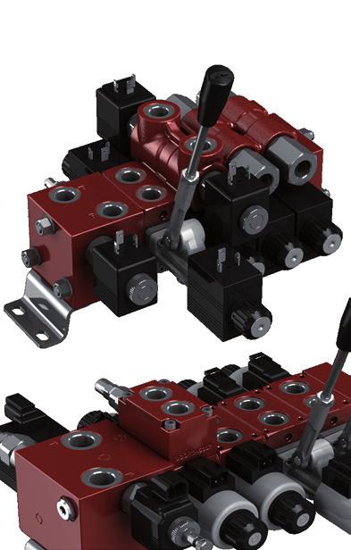

1 SDE SDE Directional control valves with direct acting solenoid
2 SDE-SDE General informations Simple, compact and heavy duty designed sectional valves from to sections. SDE luminium alloy inlet sections, available in several configurations. Cast iron working sections Different types of spools. Optional check valves on workports. vailable for parallel circuit. On/off solenoid controls. Emergency handlever available. SDE Steel inlet sections, available in several configurations. Cast iron working sections Different types of spools. Different options to be flanged on the workports side vailable for parallel and series circuits. On/off solenoid controls. Emergency handlever available. dditional information his catalogue shows the product in the most standard configurations. lease contact Sales Dpt. for more detailed information or special request. WRNING! ll specifications of this catalogue refer to the standard product at this date. Walvoil, oriented to a continuous improvement, reserves the right to discontinue, modify or revise the specifications, without notice. WLVOIL IS NO RESONSILE FOR N DGE CUSED N INCORREC USE OF HE RODUC. 5 th edition June 7 DWWEE
3 SDE-SDE Content Working conditions... Standard threads... ccessories Coils and connectors...5 Fixing brackets... Installation and maintenance... Index SDE Dimensions and hydraulic circuit...5 Complete sections ordering codes... - Inlet section art ordering codes... Dimensions and hydraulic circuit... Options... - Working section art ordering codes... Dimensions and hydraulic circuit... Spools... Control kits... Lower port relief valves... Side port relief valves... Check valves... Solenoid operated check valves... - Outlet section Dimensions and hydraulic circuit...5 SDE Dimensions...7 Hydraulic circuit...9 Complete sections ordering codes... - Inlet section art ordering codes... Dimensions and hydraulic circuit... Options Working section art ordering codes... Dimensions and hydraulic circuit...7 Lower port relief valves... Spools...9 Control kits Flangeable valve blocks ntishock valves...5 Check valves...5 Solenoid operated check valves...5 Counterbalance valves Outlet section Dimensions and hydraulic circuit...57 DWWEE
4 SDE-SDE Working conditions his catalogue shows technical specifications and diagrams measured with mineral oil of mm /s - cst viscosity at C - F temperature. SDE SDE Nominal flow rating Operating pressure (max.) l/min US gpm l/min - l/min 7.9 US gpm - 5. US gpm parallel circuit 5 bar - psi 5 bar - psi series circuit - bar - 5 psi ack pressure (max.) Internal leakage (max.) () Fluid outlet port outlet port, with lever control p = bar - 5 psi fluid and valve at C - F bar - 5 psi bar - 5 psi cm /min -.5 in /min ineral based oil Fluid temperature with NR (UN-N) seals from - C to C - from - F to 7 F with F (VION) seals from - C to C - from - F to F Viscosity operating range min. max. from 5 to 75 mm /s - from 5 to 75 cst mm s - cst mm s - cst ax. contamination level -/9/ - ISO - NS - class mbient temperature for working conditions from - C to 5 C - from - F to F NOE - For different conditions please contact Sales Dpt. Standard threads REFERENCE SNDRD S UN-UNF HRED CCORDING O CVI DIENSION CCORDING O ISO / ISO S 779 NSI. unified ISO 79 9 SE J9 DIN 5- shape or OR HREDING SDE SDE l/min (7.9 US gpm) sections l/min (5. US gpm) sections S UN-UNF S UN-UNF S UN-UNF Inlet and outlet G / /- (SE ) G / /- (SE ) G / /- (SE ) Working ports and G / 9/- (SE ) G / 9/- (SE ) G / 9/- (SE ) G /* /- (SE )* ort G / 9/- (SE ) G / 7/- (SE ) 9/- (SE )** G / 7/- (SE ) 9/- (SE )** ort LS G / 9/- (SE ) G / 9/- (SE ) / / NOE (*) Optional thread - (**) Only for type N inlet section DWWEE
5 SDE - SDE SDE Dimensions his drawing is referred to directional valve with working sections and N type inlet section. F E Ref... SDE/ 55/ product code customer reference product name production allotment Description example: SDE//N(JNG-)ELN/Q-ES/Q-ES/RF-VDC E N type inlet section N type inlet section (see drawing) N-N-N7 type inlet sections E F E F Weight E F mm in mm in mm in mm in Kg lb mm in mm in SDE/ SDE/ SDE/ SDE/ SDE/ SDE/ SDE/ SDE/ SDE/ SDE/ DWWEE 5
6 SDE SDE - SDE Complete section ordering codes SDE// N(JNG-)ELN / Q-ES / Q-ES / QL-ES / Nr. of working sections QE-ES.EN(NC) / RF VDC ie rod tightening wrench - Nm (.75 lbft) DWWEE
7 SDE - SDE SDE Complete section ordering codes Complete inlet section * page Section bodies are aluminium alloy made E: N CODE: 9G DESCRIION: Without valves arrangement, and ports open E: N CODE: 9G DESCRIION: s N, port open and plugged E: N CODE: 9G DESCRIION: s N, port plugged and open E: NS CODE: 9G DESCRIION: s N, ports and plugged E: N(JNG-)ELN-WC CODE: S DESCRIION: Relief and unloader valves arrangement, and ports open E: N(JNG-)ELN-WC CODE: S DESCRIION: s N, port open and plugged E: N/N(JNG-)ELN-WC CODE: S DESCRIION: Relief, unloader and flow control valves arrangement, and ports open E: N/N(JNG-)ELN-WC CODE: S5 DESCRIION: s N, port open and plugged E: N/EEL(VR-)-SRC(C)-WC CODE: S DESCRIION: With pressure relief valve and flow control valve, for Open Center circuit, compensator with bar (5 psi) stand-by, and ports open E: N7/EEN(VR-)-SRCV(C)-WC CODE: S7 DESCRIION: s previous one, compensator with handwheel actuation for Open to Closed Center switching, and ports open. E: N/EEN(VR-)-SRCV(C)-WC CODE: S9 DESCRIION: With pressure relief valve and flow control valve, for Closed Center Circuit with compensator blanking plug, and ports open. Complete working section * page Section bodies are cast iron made E: Q-ES-WC CODE: S DESCRIION: arallel circuit, type double acting spool E: Q-ES-WC CODE: S DESCRIION: arallel circuit, type double acting spool E: Q-ES.C-WC CODE: S DESCRIION: arallel circuit, type double acting spool, check valves on workports E: QE-ES.EN(NC)-WC CODE: S5 DESCRIION: arallel circuit, type double acting spool, solenoid operated check valves on workports E: FL(5)-ES-WC CODE: S DESCRIION: arallel circuit, type double acting spool and side relief valve with 5 bar (75 psi) E: QL-ES-WC CODE: S DESCRIION: arallel circuit, side workports, type double acting spool E: QL-ES.-WC CODE: S DESCRIION: s previous one with check valves on workports Complete outlet section* page 5 Section bodies are aluminium alloy made E CODE DESCRIION RF FI Without ports RS 9 and ports plugged R 9 port open and port plugged R 9 port open and port plugged Valve threading Specify threading always when it is different from S standard (see page ). 5 Coils page 5 Coils voltage specification; for list of available coils see pages of related sections Fixing bracket page E CODE DESCRIION SF 5S5 rackets with fixing screws 7 ssembling kit CODE DESCRIION CODE DESCRIION er distributore con fiancata d ingresso tipo N 5IR For section valve 5IR5 For sections valve 5IR5 For sections valve 5IR For 7 sections valve 5IR9 For sections valve 5IR77 For sections valve 5IR7 For sections valve 5IR For 9 sections valve 5IR For 5 sections valve 5IR9 For sections valve er distributore con fiancate d ingresso tipo N-N-N- N7-N 5IR5 For section valve 5IR For sections valve 5IR9 For sections valve 5IR77 For 7 sections valve 5IR7 For sections valve 5IR For sections valve 5IR For sections valve 5IR9 For 9 sections valve 5IR5 For 5 sections valve 5IR For sections valve NOE (*) Codes are referred to S thread. DWWEE 7
8 SDE SDE - SDE Inlet section: part ordering codes Valve setting Without coil SDE/N-... SDE/N(JNG-)ELN-WC Valve setting Without coil Valve setting SDE/N/N(JNG-)ELN-WC-... SDE/N7/EEN(VS-) SRCV(C)-WC Without coil DWWEE
9 SDE - SDE SDE Inlet section: part ordering codes Inlet section body kit * page Section bodies are aluminium alloy made E CODE DESCRIION N 5FI9 Without valves arrangement, and ports open N 5FI9 s N, port open and plugged N 5FI9 s N, port plugged and open NS 5FI9S s N, ports and plugged N 5FI9 Relief and unloader valves arrangement, and ports open N 5FI9 s N, port open and plugged N 5FI9 Relief, unloader and flow control valves arrangement, and open ports N 5FI9 s N, port open and plugged N 5FI9 For Open Center, relief and flow control valves arrangement, compensator, LS port plugged, and ports open N7/N 5FI9 s N, for Closed Center, with LS port open ain relief valve page E CODE DESCRIION For sections N-N type Valve standard setting is referred to l/min (. US gpm) flow, considering the valve mounted on inlet section. (JNG-) 5KI55 Range - bar (5-9 psi) std setting bar (9 psi) (JNG-) 5KI55 Range 5- bar (75-9 psi) std setting bar (75 psi) (JNG-) 5KI55 Range -5 bar (- psi) std setting bar ( psi) (JNH-) 5KI557 s type JNG, set and locked (JNH-) 5KI55 s type JNG, set and locked (JNH-) 5KI555 s type JNG, set and locked (JNZ-) 5KI55 s type JNG, anti-tampering type (JNZ-) 5KI55 s type JNG, anti-tampering type (JNZ-) 5KI55 s type JNG, anti-tampering type SV Relief valve blanking plug For sections N-N7-N type Valve standard setting is referred to l/min (. US gpm) flow, considering the valve mounted on inlet section. (VV-5) Range 5- bar (7- psi) std setting 5 bar (75 psi) (VS-5) Range 5- bar (75- psi) std setting 5 bar ( psi) (VR-5) Range -5 bar (-5 psi) std setting 5 bar ( psi) Solenoid operated unloading valve page E CODE DESCRIION For sections N-N type ELN EC Without emergency actuation ELV EC With screw type emergency actuation EL EC With push-button emergency actuation EL EC5 With twist & push emergency actuation L 5 Unloading valve blanking plug control valve page E CODE DESCRIION For sections N-N type L Hand-wheel setting type V 5 Screw setting type N Solenoid operated, without emergency V Solenoid operated, screw emergency L 5 Solenoid operated, hand-wheel emergency L 557 control valve blanking plug For sections N-N7-N type EEN EE9 Solenoid operated, without emergency EEL EE Solenoid operated, hand-wheel emergency 5 Compensator kit page 5 E CODE DESCRIION For section N-N7 type SRCV(C) 5K7 With bar (5 psi) stand-by, handwheel actuation for Open Center to Closed Center switching SRC(C) 5K With bar (5 psi) stand-by, for Open Center circuit For section N type CL 5 Compensator blanking plug, for Closed Center circuit Section threading Specify threading always when it is different from S standard (see page ). 7 Optional coil pag. 5 For list of available coils see pages of related section. NOE (*) Codes are referred to S thread. DWWEE 9
10 SDE SDE - SDE Inlet section: dimension and hydraulic circuit N inlet sections N type with and ports open.9.7. N type and ports open N type port open and port plugged N type port plugged and port open NS type and ports plugged - nr. holes depth = allen wrench - Nm (7.7 lbft) N inlet sections N type with and ports open N types and ports open nr. holes depth N types port open and port plugged = allen wrench - Nm (7.7 lbft) NOE: for valve wrench and torque see pages and. 9.5 Legenda : ressure relief valve : Solenoid operated unloading valve DWWEE
11 SDE - SDE SDE Inlet section: dimension and hydraulic circuit N inlet sections N type with and ports open N types and ports open 5. - nr. holes depth N types port open and port plugged Legenda : ressure relief valve : Solenoid operated unloading valve : ressure compensated flow control valve = allen wrench - Nm (7.7 lbft) NOE: for valve wrench and torque see pages,. DWWEE
12 SDE SDE - SDE Inlet section: dimension and hydraulic circuit N-N7-N inlet sections N7 type; configuration for Open and Closed Center Legenda : ressure relief valve : control valve : Excludable compensator - nr. holes depth max 7. max.9 LS = allen wrench - Nm (7.7 lbft) NOE: for valve wrench and torque see pages and N type for Open Center circuit N7 type for Closed and Open Center circuits N type for Closed Center circuit LS LS LS DWWEE
13 SDE - SDE SDE Inlet section: options ain relief valve For sections N and N type Setting types JG Z JH JZ 59. ressure Setting range: JNG type 5 7 max. setting Legenda JG: screw setting type JH: valve set and locked (cap code CO7) JZ: valve set and locked (cap code CO) = allen wrench = wrench - Nm (7.7 lbft) Z = wrench 9 - Nm (7.7 lbft) (US gpm) 5 min. setting (l/min) ressure ressure Setting range: JNG type 5 7 max. setting std. setting min. setting (US gpm) (l/min) Setting range: JNG type 5 7 max. setting std. setting min. setting (US gpm) (l/min) For sections N, N7 and N type. Z ressure Setting range: VV type 5 7 (US gpm) 5 max. setting std. setting min. setting (l/min) ressure Setting range: VS type 5 7 std. setting max. setting min. setting (US gpm) (l/min) = wrench = wrench -. Nm (.9 lbft) Z = wrench 9 - Nm (7.7 lbft) ressure Setting range: VR type 5 7 max. setting std. setting min. setting (US gpm) (l/min) DWWEE
14 SDE SDE - SDE Inlet section: options Unloading valve For sections N and N type anual emergency actuation types ELN,5 EL ELV Legenda ELN: without amergency actuation EL: push-button type emergency actuation ELV: screw type emergency actuation EL: push&twist type emergency actuation EL ressure ressure drop diagram (US gpm) 9 = wrench - Nm ( lbft) = 5 Nm (.7 lbft) (l/min) Features ax. flow...: l/min (. US gpm) ax. pressure...: bar (55 psi) Internal leakage...:.5 cm bar (.5 5 psi) For coil features and options see ER coil on pages 5 and 59. ressure compensated flow control valve For section N type anual operated Solenoid operated regulation diagram V K N (l/min) (US gpm) L K Legenda V: screw setting type L: hand-wheel setting type N: without emergency actuation V: screw type emergency actuation L: hand-wheel emergency actuation Features ax. inlet flow...: 5 l/min (. US gpm) ax. regulated flow...: l/min (7.9 US gpm) Inlet flow ( types)...: regulated flow +5% ax. pressure...: 5 bar (5 psi) - types / 5 bar ( psi) - types Internal leakage ( types). : 5 cm bar (9. in 5 psi) For coil features and options see Q9 or H coils on pages 5 and 59. W Z 9.7 V L K = wrench -. Nm (.9 lbft) = wrench 7-5 Nm (7 lbft) = 5 Nm (.7 lbft) W = allen wrench Z = wrench - 5 Nm ( lbft) (%) Valve operation (@VDC) (@VDC) (l/min) Coil current vs. ressure diagram on line on line ressure (US gpm) DWWEE
15 SDE - SDE SDE Inlet section: options ressure compensated flow control valve For sections N - N7 and N type Curves are measured using the standard compensator mounted on section, with bar (5 psi) stand-by. regulation diagram vs. ressure diagram EEN 5 (l/min) (US gpm) (l/min) (US gpm) Z Z 9. EEL (%) Valve operation ressure (@VDC) (@VDC) Coil current.5.7 Legenda EEN: without emergency actuation EEL: hand-wheel emergency actuation K = wrench -. Nm (.9 lbft) = wrench 7-5 Nm (7 lbft) = 5 Nm (.7 lbft) Z = wrench - 9. Nm (7. lbft) Features ax. flow...: l/min (. US gpm) ax. pressure...: bar (55 psi) Internal leakages...: 5 cm 5 bar (9. in 75 psi) For coil features and options see Q9 or H coils on pages 5 and 59. Compensator kit For sections N - N7 and N type SRCV(C) SRC(C) 7..7 CL max.5 max Legenda SRC(C): compensator with bar (5 psi) stand-by, for Open Center circuit CL: compensator blanking plug, for Closed Center circuit (for N type) SRCV(C): compensator with bar (5 psi) stand-by, hand-wheel actuation for Open Center to Closed Center circuit switching = wrench - Nm ( lbft) = wrench -. Nm (.9 lbft) DWWEE 5
16 SDE SDE - SDE Working section: part ordering codes Valve setting SDE/ - ES.(G-) - WC -... without coil 7 valve on port - valve on port - valve on ports and - SDE/QL - ES. - WC -... without coil 7 valve on port - valve on port - valve on ports and - SDE/QE - ES.QEN(NC) - WC -... without coil 7 DWWEE
17 SDE - SDE SDE Working section: part ordering codes Valve setting SDE/FL (5) - ES - WC without coil - valve on port - valve on port - valve on ports and 7 Working section body kit * page Section bodies are cast iron made E CODE DESCRIION Working sections with upper ports Q 5EL9 arallel type 5EL95 s type Q, lower port relief valve arrangement Q 5EL9 s type Q with check valve arrangement QE 5EL9 s type Q with solenoid operated check valve arrangement FL 5EL9 s type Q, side port relief valve arrangement Working sections with side ports QL 5EL9 arallel type, QL 5EL9 s type QL with check valve arrangement Spool page E CODE DESCRIION For ON/OFF solenoid control CU9 Double acting, and closed in neutral pos. CU9 Double acting, to tank in neutral pos. For connect to tank (type ) is necessary to turn the spool CU95 Double acting, and to tank in neutral pos. H CU955 Double acting, and partially to tank in neutral position For ON/OFF solenoid control with emergency lever operation LHD CU9 s type LHD CU9 s type LHD CU9 s type HLHD CU9 s type H On/off solenoid control page E CODE DESCRIION ES 5CNEC Single acting on port ES 5CNEC Single acting on port ES 5CNE5C Double acting ESLHD 5CNE5 Double acting with emergency lever operation: needs dedicated spools Lower port relief valves page Standard setting is referred to l/min (. US gpm) flow. E CODE DESCRIION (G-) 5KI From 5 to bar (75 to 9 psi), standard setting bar (5 psi) (G-) 5KI From to 5 bar (9 to psi), standard setting bar (9 psi) 5KI and ports valve blanking plugs 5 Side port relief valve page he codes are referred to parts with F o-ring seals E CODE DESCRIION 5 Valve blanking plug Fixed setting antishock valves: setting is referred to l/min (. US gpm) E: CODE: 5KI setting setting SEING: bar (5 psi) 5 bar (75 psi) bar (7 psi) bar (5 psi) bar (5 psi) bar (75 psi) bar (9 psi) bar (5 psi) 5 bar (5 psi) 5 bar ( psi) 75 bar (55 psi) 5 bar (7 psi) bar (9 psi) bar (5 psi) bar ( psi) 5 bar ( psi) 5 bar ( psi) Check valve page E CODE DESCRIION For arranged setions with upper ports, Q type C 5KI Valves kit for and ports C-C 5KI Valve kit por single port For arranged setions with upper ports, QE type 5 Valve blanking plug Normally closed circuit (NC) EN(NC) EC Without manual emergency EV(NC) EC7 With screw type emergency E(NC) EC With pull-button emergency E(NC) EC With pull & twist emergency Normally open circuit (NO) EN(N) EC Without manual emergency EV(N) EC With screw type emergency E(N) EC With push-button emergency E(N) EC5 With push & twist emergency For arranged setions with side ports, QL type 5KI Valves kit for and ports - 5KI Valve kit for single port 7 Section threading Specify threading always when it is different from S standard (see page ). Optional coils page 5 For list of available coils see pages of related section. NOE (*) Codes are referred to S thread. DWWEE 7
18 SDE SDE - SDE Working section Dimension and hydraulic circuit Working section Q type with upper ports Q type type with lower port relief valves arrangement 7.. Valve fixing plan ressure..9. through pressure drop 5 7 (US gpm) 5 Q type example (with spool ) type example (with spool ) (l/min) FL type with side port relief valves arrangement.5.7 FL type example (with spool ) Valve fixing plan DWWEE
19 SDE - SDE SDE Working section Spools Working section with upper ports Q - QE types with check valve arrangement Q type example (with spool ) Working section with side ports QL - QL types with or without check valves arrangement Valve fixing plan 7. QL type example (with spool ). Valve fixing plan DWWEE 9
20 SDE SDE - SDE Working section Spool ypes -LHD Double acting, and closed in neutral position ypes -LHD Double acting, to tank in neutral position ypes -LHD Double acting, and to tank in neutral position Stroke position : + mm (+. in) position : - mm (-. in) Stroke position : + mm (+. in) position : - mm (-. in) Stroke position : + mm (+. in) position : - mm (-. in) port - port pressure drops (curves are matched) ressure 5 7 (US gpm) 5 ressure port - port pressure drops (curves are matched) 5 7 (US gpm) (l/min) (l/min) ypes H-HLHD Double acting, and partially to tank in neutral position Stroke position : + mm (+. in) position : - mm (-. in) ressure port - port pressure drops (curves are matched) 5 7 (US gpm) (l/min) DWWEE
21 SDE - SDE SDE Working section On/off solenoid control: ES - ES - ES types When the section is configurated with check valves, the coils on control must be rotated. ES: double acting control kit ES: single acting on control kit Z ressure (US gpm) 5 Operating condition (stroke mm -. in) (l/min) Wrenches and tightening torque = wrench 7 - Nm (7.7 lbft) =. Nm (.9 lbft) Z = wrench - Nm (7.7 lbft) For coil features and options see DC coil on pages 5 and. ES: single acting on control kit..5 Z On/off solenoid control with lever: ESLHD type When the section is configured with side ports or with check valves, control and coils must be rotated. If the section is configured with solenoid check valves the control can t be used. he control needs dedicated spools: see page 7 for list. IORN: lever to be used only for emergency operation, not for continuative use. J : idle stroke angles : total operation angles K J = wrench - 9. Nm (7. lbft) K = allen wrench -. Nm (.9 lbft) = wrench 7 - Nm (7.7 lbft) =. Nm (.9 lbft) Control features ax. back pressure on. : bar (5 psi) For coil features and options see DC coil on pages 5 and. DWWEE
22 SDE SDE - SDE Working section Lower port relief valves G type Setting range: G type (US gpm) 5 Z H type.5. ressure max. setting min. setting 5 (l/min) Setting range: G type Legenda G: screw setting type H: valve set and locked Side port relief valves = wrench 7 - Nm (7.7 lbft) = wrench -. Nm (.9 lbft) Z = allen wrench.5 ressure (US gpm) max. setting min. setting 5 5 (l/min) (US gpm) 5 ressure ressure drop (working section included port port = wrench - Nm ( lbft) ressione (l/min) Setting example ( l/min -. US gpm) (US gpm) 5 5 bar ( psi) bar (9 psi) 5 bar (5 psi) bar (5 psi) bar (5 psi) (l/min) ortata DWWEE
23 SDE - SDE SDE Working section Check valves When the section is configurated with check valves, the coils on control must be rotated. For sections with upper ports C type C type C type = wrench - Nm ( lbft) arts ordering codes E CODE DESCRIION Check valve 7 Valve blanking plug - IS iston ressure 5 5 ressure drop diagram (working section included) (US gpm) port port (l/min) For sections with side ports ressure drop diagram (working section included) (US gpm) type = wrench - 5 Nm (7 lbft) ressure 5 port port (l/min) arts ordering codes E CODE DESCRIION C Check valve - IS iston DWWEE
24 SDE SDE - SDE Working section Solenoid operated check valves When the section is configurated with check valves, the coils on control must be rotated. For sections wiht upper ports E(NC) type: normally closed circuit 9..5 EN EN(NC) type EN(NC) type EN(NC) type EV E EG E(N) type: normally open circuit 5. EN EN(N) type EN(N) type EN(N) type EV E EG.. = wrench - Nm ( lbft) = 5 Nm (.7 lbft) Legenda EN: without amergency actuation E: push-button type emergency actuation EV: screw type emergency actuation E: push&twist type emergency actuation 9.5 ressure 5 5 ressure drop diagram (working section included) (US gpm) port port (l/min) DWWEE
25 SDE - SDE SDE Outlet section Dimensions and hydraulic circuit Without port arrangement RF type With port arrangement RS - R - R types drawing shows RS type nr. holes depth nr. holes depth = allen wrench - Nm (7.7 lbft) = allen wrench - Nm (7.7 lbft) RS type and ports plugged R type open, plugged R type open, plugged DWWEE 5
26 SDE SDE - SDE DWWEE
27 SDE Dimensions his drawing is referred to directional valve with mixed working sections ( sections up to l/min-5. US gpm and sections up to l/min-7.9 US gpm), and N type inlet section. F E Ref... SDE/ 55/ product code customer reference product name production allotment N type inlet section N type inlet section (see drawing) N type inlet section E E F E F Weight E F mm in mm in mm in mm in Kg lb mm in mm in SDE/ SDE/ SDE/ SDE/ SDE/ SDE/ SDE/ SDE/ SDE/ SDE/ DWWEE 7
28 SDE Dimensions his drawing is referred to directional valve with all working sections up to l/min (up to 7.9 US gpm), and N type inlet section. F E Ref... SDE/ 55/ product code customer reference product name production allotment E N type inlet section N type inlet section (see drawing) E F E F Weight mm in mm in mm in mm in Kg lb SDE/ SDE/ SDE/ SDE/ SDE/ SDE/ SDE/ SDE/ SDE/ SDE/ E N type inlet section N-N7 type inlet sections E F E F mm in mm in mm in mm in SDE/ SDE/ SDE/ SDE/ SDE/ SDE/ SDE/ SDE/ SDE/ SDE/ DWWEE
29 SDE Hydraulic circuit arallel circuit parallel circuit can be composed using or Q working sections. he outlet section can be with or without port arrangement. Description example: SDE//N(GW-75)ELN/Q-ES/Q-ES/RF-VDC Series circuit: only for l/min (5. US gpm) sections he series circuit is composed using alternately QS and Q working sections, both with S series spool. he circuit starts always with QS working section. he outlet section depends on total number of working sections: if it is even, the outlet section must have port open, if it is odd, the outlet section must have port open. Description example: SDE//N(GW-75)ELN/QS-SESSE/Q-SESSE/R-VDC Description example: SDE//N(GW-75)ELN/QS-SESSE/Q-SESSE/QS-SESSE/R-VDC DWWEE 9
30 SDE Complete section ordering codes SDE//N(GW-)ELN/Q-ES/Q-ES.EN/Q-ES/ Nr. of working sections Q-ES.S(DC-)/RF-...-VDC 5 ie rod tightening wrench - Nm (.75 lbft) 7 SDE//N(JNG-)ELN/Q-ES/Q-ES.S(DC-)/RF-...-VDC Nr. of working sections 5 ie rod tightening wrench - Nm (.75 lbft) 7 DWWEE
31 SDE Complete section ordering codes Complete inlet section * page Section bodies are steel made E: N CODE: 5FI DESCRIION: Without valves arrangement, G/ ports and open E: N CODE: 5FI DESCRIION: s previous one, G/ ports, up to l/min (7.9 US gpm) E: N CODE: 5FI DESCRIION: s type N, port open and plugged E: N CODE: 5FI DESCRIION: s previous one, G/ ports, up to l/min (7.9 US gpm) E: N CODE: 5FI DESCRIION: s type N, port plugged and open E: N CODE: 5FI DESCRIION: s previous one, G/ ports, up to l/min (7.9 US gpm) E: NS CODE: 5FI5 DESCRIION: s type N, ports and plugged E: NS CODE: 5FI DESCRIION: s previous one, G/ ports, up to l/min (7.9 US gpm) E: N(GW-75)ELN-WC CODE: S DESCRIION: With pressure relief valve and solenoid operated unloading valve, G/ ports and open E: N(JNG-)ELN-WC CODE: S DESCRIION: s previous one, G/ ports, up to l/min (7.9 US gpm) E: N(GW-75)ELN-WC CODE: S DESCRIION: s type N port open and plugged E: N(JNG-)ELN-WC CODE: S DESCRIION: s previous one, G/ ports, up to l/min (7.9 US gpm) E: N/N(GW-75)ELN-WC CODE: S DESCRIION: With pressure relief valve, solenoid operated unloading valve and pressure compensated flow control valve, G/ ports and open E: N/N(JNG-)ELN-WC CODE: S DESCRIION: s previous one, G/ ports, up to l/min (7.9 US gpm) E: N/N(GW-75)ELN-WC CODE: S DESCRIION: s type N, port open and plugged E: N/N(JNG-)ELN-WC CODE: S5 DESCRIION: s previous one, G/ ports, up to l/min (7.9 US gpm) E: N/EEL(VR-)-S7RC(C5)-WC CODE: S DESCRIION: With pressure relief valve and flow control valve, for Open Center circuit, compensator with 7 bar ( psi) stand-by, G/ ports and open E: N/EEL(VR-)-SRC(C)-WC CODE: S DESCRIION: With pressure relief valve and flow control valve, for Open Center circuit, compensator with bar (5 psi) stand-by, G/ ports and open, up to l/min (7.9 US gpm) E: N7/EEL(VR-)-S7RCV(C5)-WC CODE: S DESCRIION: s N, compensator with handwheel actuation for Open to Closed Center switching, G/ ports and open. E: N7/EEN(VR-)-SRCV(C)-WC CODE: S7 DESCRIION: s N, compensator with handwheel actuation for Open to Closed Center switching, G/ ports and open, up to l/min (7.9 US gpm) E: N/EEN(VR-)-CL-WC CODE: S DESCRIION: s N, for Closed Center circuit, compensator blanking plug, G/ ports and open E: N/EEN(VR-)-CL-WC CODE: S DESCRIION: s N, for Closed Center circuit, compensator blanking plug, G/ ports and open, up to l/min (7.9 US gpm) Complete working section * page Section bodies are cast iron made Sections are arranged for flangeable valve blocks E CODE DESCRIION Q-ES-WC SC arallel circuit, type double acting spool Q-ES-WC SC s previous one, up to l/min (7.9 US gpm) Q-ES-WC SC arallel circuit, type double acting spool Q-ES-WC SC s previous one, up to l/min (7.9 US gpm) QS-SESSE-WC SC Series circuit, type S double acting series spool Q-SESSE-WC S5C arallel circuit, type S double acting series spool: placed after QS series section only Complete outlet section* page 57 Unless otherwise stated, outlet section bodies are steel made. E CODE DESCRIION RF FI Without ports, aluminium alloy body RS 9 G/ ports, and plugged RS 9 s previous one with G/ ports, up to l/min (7.9 US gpm) R 9 G/ ports, open and plugged R 9 s previous one with G/ ports, up to l/min (7.9 US gpm) R 9 G/ ports, open and plugged R 9 s previous one with G/ ports, up to l/min (7.9 US gpm) Complete flangeable valve block ntishock valves...page 5 Check valves...page 5 Solenoid operated check valves (without coils)...page 5 Single counterbalance valves...page 55 Double counterbalance valves...page 5 5 Valve threading Specify threading always when it is different from S standard (see page ). Coils page 5 Coils voltage specification; for list of available coils see pages of related sections 7 Fixing bracket page E CODE DESCRIION SF 5S5 rackets with fixing screws ssembling kit CODE DESCRIION CODE DESCRIION 5IR99 For section valve 5IR9 For section valve 5IR For sections valve 5IR75 For 7 sections valve 5IR9 For sections valve 5IR For sections valve 5IR For sections valve 5IR For 9 sections valve 5IR For 5 sections valve 5IR5 For sections valve NOE (*) Codes are referred to S thread. DWWEE
32 SDE Inlet section: part ordering codes Valve setting Valve setting SDE/N-... SDE/N-... SDE/N7/EEN(VS-) S7RCV(C5)-WC-... SDE/N7/EEN(VS-) SRCV(C)-WC Without coil 5 Without coil N N Valve setting Without coil Valve setting Without coil SDE/N(GW-75)ELN-WC-... SDE/N(JNG-)ELN-WC-... SDE/N/N(GW-75)ELN-WC-... SDE/N/N(JNG-)ELN-WC-... N 7 N N N 7 7 DWWEE
33 SDE Inlet section: part ordering codes Inlet section body kit * page Section bodies are steel made E CODE DESCRIION N 5FI Without valves arrangement, G/ ports, and open N 5FI s N, G/ ports, up to l/min (7.9 US gpm) N 5FI s N, port open and plugged N 5FI s N, G/ ports, up to l/min (7.9 US gpm) N 5FI s N, port plugged and open N 5FI s N, G/ ports, up to l/min (7.9 US gpm) NS 5FI5 s N, ports and plugged NS 5FI s NS, G/ ports, up to l/min (7.9 US gpm) N 5FI7 Relief and unloader valves arrangement, G/ ports, and open N 5FI s N, port open and plugged N 5FI s N, G/ ports, up to l/min (7.9 US gpm) N 5FI s N, G/ ports, up to l/min (7.9 US gpm) N 5FI Relief, unloader and flow control valves arrangement, G/ ports, and open N 5FI5 s N, port open and plugged N 5FI9 s N, G/ ports, up to l/min (7.9 US gpm) N 5FI s N, G/ ports, up to l/min (7.9 US gpm) N 5FI For Open Center, relief and flow control valves arrangement, compensator, LS port plugged, G/ and ports open N 5FI For Open Center, relief and flow control valves arrangement, compensator, LS port plugged, G/ and ports open, up to l/min (7.9 US gpm) N7/N 5FI s N, for Closed Center, with LS port open N7/N 5FI7 s N, for Closed Center, with LS port open, up to l/min (7.9 US gpm) ain relief valve page 9 E CODE DESCRIION For sections N-N type Valve standard setting is referred to 5 l/min (. US gpm) flow. (GW-) C Range - bar (5-75 psi) std setting bar ( psi) (GW-75) C Range - bar (5-9 psi) std setting 75 bar (55 psi) (GW-5) C5 Range -5 bar (9-5 psi) std setting 5 bar ( psi) SV 5 Relief valve blanking plug For sections N-N type Valve standard setting is referred to l/min (. US gpm) flow, considering the valve mounted on inlet section. (JNG-) 5KI55 Range - bar (5-9 psi) std setting bar (9 psi) (JNG-) 5KI55 Range 5- bar (75-9 psi) std setting bar (75 psi) (JNG-) 5KI55 Range -5 bar (- psi) std setting bar ( psi) (JNH-) 5KI557 s type JNG, set and locked (JNH-) 5KI55 s type JNG, set and locked (JNH-) 5KI555 s type JNG, set and locked (JNZ-) 5KI55 s type JNG, anti-tampering type (JNZ-) 5KI55 s type JNG, anti-tampering type (JNZ-) 5KI55 s type JNG, anti-tampering type SV Relief valve blanking plug For sections N-N7-N-N7-N-N type Valve standard setting is referred to l/min (. US gpm) flow, considering the valve mounted on inlet section. (VV-5) Range 5- bar (7- psi) std setting 5 bar (75 psi) (VS-5) Range 5- bar (75- psi) std setting 5 bar ( psi) (VR-5) Range -5 bar (-5 psi) std setting 5 bar ( psi) Solenoid operated unloading valve page E CODE DESCRIION For sections N-N type ELN EC Without emergency override ELV EC5 With screw type emergency override EL EC With push-button emergency override EL EC With twist & push emergency override L 5 Unloading valve blanking plug For sections N-N type ELN EC Without emergency actuation ELV EC With screw type emergency actuation EL EC With push-button emergency actuation EL EC5 With twist & push emergency actuation L 5 Unloading valve blanking plug control valve page E CODE DESCRIION For sections N type L Hand-wheel setting type V Screw setting type N 7 Solenoid operated, without emergency V 9 Solenoid operated, screw emergency L Solenoid operated, hand-wheel emergency L 55 control valve blanking plug For sections N type L Hand-wheel setting type V 5 Screw setting type N Solenoid operated, without emergency V Solenoid operated, screw emergency L 5 Solenoid operated, hand-wheel emergency L 557 control valve blanking plug For sections N-N7-N type EEN EE7 Solenoid operated, without emergency EEL EE9 Solenoid operated, hand-wheel emergency For sections N-N7-N type EEN EE9 Solenoid operated, without emergency EEL EE Solenoid operated, hand-wheel emergency 5 Compensator kit page E CODE DESCRIION For section type N S7RC(C5) 5K With 7 bar ( psi) stand-by, for Open Center circuit For section type N7 S7RCV(C5) 5K With 7 bar ( psi) stand-by, handwheel actuation for Open Center to Closed Center switching For section type N SRC(C) 5K With bar (5 psi) stand-by, for Open Center circuit For section type N7 SRCV(C) 5K7 With bar (5 psi) stand-by, handwheel actuation for Open Center to Closed Center switching For section type N-N CL 5 Compensator blanking plug, for Closed Center circuit Section threading Specify threading always when it is different from S standard (see page ). 7 Optional coil page 5 For list of available coils see pages of related section. NOE (*) Codes are referred to S thread. DWWEE
34 SDE Inlet section: dimension and hydraulic circuit N-N inlet sections N type with and ports open N type with and ports open nr. holes depth nr. holes depth = allen wrench - Nm (7.7 lbft) N-N type and ports open N-N type port open and port plugged N-N type port plugged and port open NS-NS type and ports plugged DWWEE
35 SDE Inlet section: dimension and hydraulic circuit N-N inlet sections N type with and ports open N type with and ports open nr. holes depth nr. holes depth Legenda : ressure relief valve : Solenoid operated unloading valve = allen wrench - Nm (7.7 lbft) NOE: for valve wrench and torque see pages 9 and. N-N types and ports open N-N types port open and port plugged DWWEE 5
36 SDE Inlet section: dimension and hydraulic circuit N-N inlet sections N type with and ports open.. - nr. holes depth Legenda : ressure relief valve : Solenoid operated unloading valve : ressure compensated flow control valve = allen wrench - Nm (7.7 lbft) NOE: for valve wrench and torque see pages from 9 to N-N types and ports open N type with and ports open nr. holes depth N-N types port open and port plugged DWWEE
37 SDE Inlet section: dimension and hydraulic circuit N-N7-N inlet sections N7 type; configuration for Open and Closed Center.5.9. Legenda : ressure relief valve : control valve : Excludable compensator = allen wrench - Nm (7.7 lbft) NOE: for valve wrench and torque see pages and. - nr. holes depth LS N type for Open Center circuit N7 type for Closed and Open Center circuits N type for Closed Center circuit LS LS LS DWWEE 7
38 SDE Inlet section: dimension and hydraulic circuit N-N7-N inlet sections N7 type; configuration for Open and Closed Center Legenda : ressure relief valve : control valve : Excludable compensator = allen wrench - Nm (7.7 lbft) = allen wrench - 9. Nm (7. lbf) NOE: for valve wrench and torque see pages and 5. - nr. holes depth -.9 max 7. max LS N type for Open Center circuit N7 type for Closed and Open Center circuits N type for Closed Center circuit LS LS LS DWWEE
39 SDE Inlet section: options ain relief valve For sections N and N type Setting types GW Z.9 ZW 5. Legenda GW: screw setting type ZW: with anti-tampering cap (cap code CO, nr. pcs) ressure = allen wrench 5 = wrench 9 - Nm (. lbft) Z = wrench 7-5 Nm (7 lbft) For sections N and N type Setting range: GW type 9 5 (US gpm) 5 max. setting std. setting min. setting 5 (l/min) ressure ressure Setting range: GW type 9 5 (US gpm) max. setting std. setting min. setting 5 5 (l/min) Setting range: GW type 9 5 (US gpm) max. setting std. setting min. setting 5 5 (l/min) Setting types JG Z JH JZ 59. ressure Setting range: JNG type 5 7 max. setting Legenda JG: screw setting type JH: valve set and locked (cap code CO7) JZ: valve set and locked (cap code CO) = allen wrench = wrench - Nm (7.7 lbft) Z = wrench 9 - Nm (7.7 lbft) (US gpm) 5 min. setting (l/min) ressure ressure Setting range: JNG type 5 7 max. setting std. setting min. setting (US gpm) (l/min) Setting range: JNG type 5 7 max. setting std. setting min. setting (US gpm) (l/min) DWWEE 9
40 SDE Inlet section: options ain relief valve For sections N - N7 - N - N - N7 and N type. Z ressure Setting range: VV type 9 5(US gpm) 5 max. setting std. setting min. setting 5 (l/min) ressure Setting range: VS type 9 5(US gpm) std. setting max. setting min. setting 5 5 (l/min) = wrench = wrench -. Nm (.9 lbft) Z = wrench 9 - Nm (7.7 lbft) ressure Setting range: VR type 9 5(US gpm) max. setting std. setting min. setting 5 5 (l/min) DWWEE
41 SDE Inlet section: options Unloading valve For sections N and N type anual emergency actuation types ELN.5. ressure ressure drop diagram 9 5 (US gpm) EL ELV EL 9. 5 (l/min) Legenda ELN: without amergency actuation EL: push-button type emergency actuation ELV: screw type emergency actuation EL: push&twist type emergency actuation = wrench 7-5 Nm (7 lbft) = 5 Nm (.7 lbft) Features ax. flow...: l/min (. US gpm) ax. pressure...: bar (55 psi) Internal leakage...:.5 cm bar (.5 in 5 psi) For coil features and options see ER coil on pages 5 and 59 For sections N and N type anual emergency actuation types ELN ressure drop diagram (US gpm).5. ressure 9 EL ELV EL (l/min) Legenda ELN: without amergency actuation EL: push-button type emergency actuation ELV: screw type emergency actuation EL: push&twist type emergency actuation = wrench - Nm ( lbft) = 5 Nm (.7 lbft) Features ax. flow...: l/min (. US gpm) ax. pressure...: bar (55 psi) Internal leakage...:.5 cm bar (.5 5 psi) For coil features and options see ER coil on pages 5 and 59 DWWEE
42 SDE Inlet section: options ressure compensated flow control valve For section N type anual operated Solenoid operated regulation diagram V (l/min) 5 5 (US gpm) K K N 9. L 5.77 W Z 97. V.7 L 5 (%) Valve operation (@VDC) (@VDC) Coil current Legenda V: screw setting type L: hand-wheel setting type N: without emergency actuation V: screw type emergency actuation L: hand-wheel emergency actuation K = wrench -. Nm (.9 lbft) = wrench - Nm (59 lbft) = 5 Nm (.7 lbft) W = allen wrench Z = wrench - 5 Nm ( lbft) (l/min) 5 vs. ressure diagram 5 (US gpm) 9 5 on line on line ressure Features ax. inlet flow...: 9 l/min (. US gpm) ax. regulated flow...: 5 l/min (. US gpm) - types l/min ( US gpm) - types Inlet flow ( types)...: regulated flow +5% ax. pressure...: 5 bar (5 psi) - types 5 bar ( psi) - types Internal leakage ( types)..: 5 cm /min a bar (5. in 5 psi) For coil features and options see Q9 or H coils on pages 5 and 59. DWWEE
43 SDE Inlet section: options ressure compensated flow control valve For section N type anual operated Solenoid operated regulation diagram V K K.5. L 5.77 W Z N 9.7 V. L (l/min) (US gpm) (%) Valve operation (@VDC) (@VDC) Coil current Legenda V: screw setting type L: hand-wheel setting type N: without emergency actuation V: screw type emergency actuation L: hand-wheel emergency actuation K = wrench -. Nm (.9 lbft) = wrench 7-5 Nm (7 lbft) = 5 Nm (.7 lbft) W = allen wrench Z = wrench - 5 Nm ( lbft) (l/min) vs. ressure diagram on line on line (US gpm) ressure Features ax. inlet flow...: 5 l/min (. US gpm) ax. regulated flow...: l/min (7.9 US gpm) Inlet flow ( types)...: regulated flow +5% ax. pressure...: 5 bar (5 psi) - types 5 bar ( psi) - types Internal leakage ( types)..: 5 cm bar (9. in 5 psi) For coil features and options see Q9 or H coils on pages 5 and 59. DWWEE
44 SDE Inlet section: options ressure compensated flow control valve For sections N-N7-N type Curves are measured using the standard compensator mounted on section, with 7 bar ( psi) stand-by. regulation diagram vs. ressure diagram EEN (l/min) (US gpm) (l/min) (US gpm) Z Z 9..7 EEL (%) Valve operation ressure (@VDC) (@VDC) Coil current..9 Legenda EEN: without emergency actuation EEL: hand-wheel emergency actuation K = wrench -. Nm (.9 lbft) = wrench - Nm (59 lbft) = 5 Nm (.7 lbft) Z = wrench - 9. Nm (7. lbft) Features ax. flow...: l/min (5. US gpm) ax. pressure...: 5 bar (5 psi) Internal leakages...: cm 5 bar (. in 75 psi) For coil features and options see Q9 or H coils on pages 5 and 59. Compensator kit For sections N-N7-N type S7RCV(C5) SRC(C) 7..7 CL max.5 max Legenda S7RC(C5): compensator with 7 bar ( psi) stand-by, for Open Center circuit CL: compensator blanking plug, for Closed Center circuit (for N type) S7RCV(C5): compensator with 7 bar ( psi) stand-by, hand-wheel actuation for Open Center to Closed Center circuit switching c.c. c.a. = wrench - Nm ( lbft) = wrench -. Nm (.9 lbft) DWWEE
45 SDE Inlet section: options ressure compensated flow control valve For sections N-N7-N type Curves are measured using the standard compensator mounted on section, with bar (5 psi) stand-by. regulation diagram vs. ressure diagram EEN 5 (l/min) (US gpm) (l/min) (US gpm) Z Z 9. EEL (%) Valve operation ressure (@VDC) (@VDC) Coil current.5.7 Legenda EEN: without emergency actuation EEL: hand-wheel emergency actuation K = wrench -. Nm (.9 lbft) = wrench 7-5 Nm (7 lbft) = 5 Nm (.7 lbft) Z = wrench - 9. Nm (7. lbft) Features ax. flow...: l/min (. US gpm) ax. pressure...: bar (5 psi) Internal leakages...: 5 cm 5 bar (9. in 75 psi) For coil features and options see Q9 or H coils on pages 5 and 59. Compensator kit For sections N-N7-N type SRCV(C) SRC(C) 7..7 CL max.5 max Legenda SRC(C): compensator with bar (5 psi) stand-by, for Open Center circuit CL: compensator blanking plug, for Closed Center circuit (for N type) SRCV(C): compensator with bar (5 psi) stand-by, hand-wheel actuation for Open Center to Closed Center circuit switching c.c. c.a. = wrench - Nm ( lbft) = wrench -. Nm (.9 lbft) DWWEE 5
46 SDE Working section: part ordering codes Valve setting SDE / - ES. (G-) - WC -... without coil 5 Working section body kit * page 7 Section bodies are cast iron made E CODE DESCRIION Sections with standard threads: G/ Q 5EL arallel type, with arrangement for upper flangeable valve block QS 5EL s type Q, for series circuit: need spool type S #. Only for section up to l/min (5. US gpm) Q() 5EL5 s type Q, for regenerative circuit on port : need spool type 5EL s type Q, with arrangement for secondary relief valve Sections with increased threads: G/ NF-S 5EL arallel type, without arrangement for upper flangeable valve block QSNF-S 5EL s type Q, for series circuit: needs spool type S #. Only for SDE valve QNF()-S 5EL5 s type Q, for regenerative circuit on port : needs spool type NF-S 5EL s type Q, with arrangement for secondary port valves On/off solenoid control page 5 E CODE DESCRIION For section up to l/min (5. US gpm) ES 5CNEC Single acting on port ES 5CNEC Single acting on port ES 5CNEC Double acting ESLHD 5CNE Double acting with emergency lever operation: needs dedicated spools ESSE 5CNEC Double acting: for spool type S # For section up to l/min (7.9 US gpm) ES 5CNEC Single acting on port ES 5CNEC Single acting on port ES 5CNE5C Double acting ESLHD 5CNE5 Double acting with emergency lever operation: needs dedicated spools Spool page 9 E CODE DESCRIION For ON/OFF solenoid control CU9 Double acting, and closed in neutral pos. CU9 Double acting, to tank in neutral pos. For connect to tank (type ) is necessary to turn the spool CU95 Double acting, and to tank in neutral pos. H CU955 Double acting, and partially to tank in neutral position S CU9 Double acting, for series circuit: needs control type ESSE and section type QS-QSNF # CU9 Double acting, for regenerative circuit, for l/min (7.9 US gpm): needs section type Q For ON/OFF solenoid control with emergency lever operation LHD CU9 s type LHD CU9 s type LHD CU9 s type HLHD CU9 s type H ort relief valves page Standard setting is referred to l/min (. US gpm) flow. E CODE DESCRIION (G-) 5KI From 5 to bar (75 to 9 psi), standard setting bar (5 psi) (G-) 5KI From to 5 bar (9 to psi), standard setting bar (9 psi) 5KI and ports valve blanking plugs 5 Section threading Specify threading always when it is different from S standard (see page ). Optional coils page 5 For list of available coils see pages of related sections NOES (#) For Series circuit configuration rules see page 9. NOS (*) Codes are referred to S thread. DWWEE
47 SDE Working section Dimensions and hydraulic circuit Working section Q type.5. Q type: parallel circuit (with spool type ) Q type: regenerative circuit (needs spool type ) 7.5. Valve fixing plan Standard port thread: G/ with arrangement for valve blocks QS type for series circuit (needs spool type S) Increased port thread: G/ without arrangement for valve blocks (NF type) ressure..9. through pressure drop (parallel and regenerative circuits) 9 5 (US gpm) (US gpm) ressure through pressure drop (QS series section with S spool). 5 5 (l/min) 5 (l/min) DWWEE 7
48 SDE Working section Dimension and hydraulic circuit Working section type With arrangement for secondary port valves. type section is available also with increased port threads (G/): see Q type section for dimensional data type: parallel circuit (with spool type ) Valve fixing plan ort relief valves G type Setting range: G type (US gpm) 5 Z H type.5. ressure max. setting min. setting 5 (l/min) Setting range: G type Legenda G: screw setting type H: valve set and locked ressure (US gpm) max. setting 5 min. setting = wrench 7 - Nm (7.7 lbft) = wrench -. Nm (.9 lbft) Z = allen wrench.5 5 (l/min) DWWEE
49 SDE Working section Spools ypes -LHD Double acting, and closed in neutral position ypes -LHD Double acting, to tank in neutral position ypes -LHD Double acting, and to tank in neutral position Stroke position : + mm (+. in) position : - mm (-. in) Stroke position : + mm (+. in) position : - mm (-. in) Stroke position : + mm (+. in) position : - mm (-. in) port - port pressure drops (curves are matched) 9 5 (US gpm) port - port pressure drops (curves are matched) 9 5 (US gpm) ressure ressure 5 (l/min) 5 (l/min) ypes H-HLHD Double acting, and partially to tank in neutral position ypes S Double acting, for series circuit ypes Double acting, for regenerative circuit Stroke position : + mm (+. in) position : - mm (-. in) Stroke position : + mm (+. in) position : - mm (-. in) Stroke position : + mm (+. in) position : - mm (-. in) ressure port - port pressure drops (curves are matched) 9 5 (US gpm) ressure port - port pressure drops (curves are matched) 9 5 (US gpm) ressure port - port pressure drops indicated for l/min (7.9 US gpm) max (US gpm) 9 5 (l/min) 5 (l/min) (l/min) DWWEE 9
SDE030 SDE060. Directional control valves with direct acting solenoid
 SDE SDE6 Directional control valves with direct acting solenoid SDE-SDE6 Features Simle, comact and heavy duty designed sectional valve from to sections. Different tye of inlet covers. Different tyes of
DFE10. solenoid control monoblock valve. Ordering codes. Description example : Diverter valve DFE10/3 A 18 ES - W VDC - SAE - <CVN>
 DFE1 Ordering codes Description example : Diverter valve DFE1/3 18 ES - W 22-12VDC - SE - 1. 4. 5. 3. 5. 2. Valve is supplied painted as standard, with one coat of rimer black antirust paint II 5.
SDS400. Sectional directional control valve
 SDS4 Sectional directional control valve SDS4 Features Sectional directional control valve for high flow, available for fixed displacements hydraulic pumps. From to work sections Open centre Optional carry-over
TESTO ITC KORINNA 28mm Allargato LOAD SENSING MONOBLOCK DIRECTIONAL CONTROL VALVE
 ESO IC KORINN 28mm llargato LOD SENSING MONOLOCK DIRECIONL CONROL VLVE Features Simple, compact and heavy duty designed 2 sections monoblock valve, for hydraulic systems with load sensing variable displacement
COMPACT CATALOG MONOBLOCK DIRECTIONAL CONTROL VALVES
 COMAC CAALOG MONOBLOCK DIRECIONAL CONROL VALVES SD4 Features Simple, compact designed, this valves is only one section for open center and closed center hydraulic systems. H Fittedwithamainpressurereliefvalve.
COMPACT CATALOG MONOBLOCK DIRECTIONAL CONTROL VALVES
 COMAC CAALOG MONOBLOCK DIRECIONAL CONROL VALVES Features Simple, compact designed, this valve is only one section for open center and closed center hydraulic systems. H Fitted with a main pressure relief
COMPACT CATALOGUE SECTIONAL DIRECTIONAL CONTROL VALVES
 COMAC CAALOGUE SECIONAL DIRECIONAL CONROL VALVES Features Simple, compact and heavy duty designed sectional valve from to sections for open and closed centre hydraulic systems. H Fitted with a main pressure
SDH Series. Monoblock and Sectional directional valves
 SDH Series Monoblock and Sectional directional valves Additional information his catalogue shows the product in the most standard configurations. lease contact Sales Dpt. for more detailed information
COMPACT CATALOGUE SECTIONAL DIRECTIONAL CONTROL VALVES
 COMAC CAALOGUE SECIONAL DIRECIONAL CONROL VALVES SDS5 Features Simple, compact and heavy duty designed sectional valve from to sections for open and closed centre hydraulic systems. H Fitted with a main
SECTIONAL DIRECTIONAL CONTROL VALVES
 SECIONL DIRECIONL CONROL VLVES SDS Simple, compact and heavy duty designed sectional valve from to sections for open and closed centre hydraulic systems. H Fitted with a main pressure relief valve and
Available manual, pneumatic, and hydraulic spool control kits.
 Fitted with a main pressure relief valve and a load check valve on every working section. Available with parallel circuit. Optional carry-over Variety of port valves (auxiliary valves) Available manual,
DFE. solenoid control monoblock valve. Content. Working conditions Hydraulic circuit DFE052. Dimensional data Ordering codes...
 DFE Content Working conditions... 54 Hydraulic circuit... 55 DFE52 DFE1 DFE2 Dimensional data... 6 Ordering codes... 64 Positioner kits... 67 Solenoid parts... 68 Dimensional data... 69 Ordering codes...
Umschaltventile Magnet
 Umschaltventile Magnet DFE 52/2 und DFE52/3 estellnr. Typ 25-1-1 DFE52/318ES-W1-12VDC 25-1-11 DFE52/318ES-W1-24VDC -1465 DFE52/318ES-Y1-12VDC -147 DFE52/318ES-Y1-24VDC Weitere Umschaltventil Varianten
Monoblock Directional Control Valve HDM11S/3PQ
 Monoblock Directional Control Valve djustable priority flow to the first section (for agricultural applications) Reference: 200--991229-EN-00 Issue: 09.2015 1/24 Contents age 1 General information... 3
SDS180 DLS180. Sectional directional control valve
 SDS8 DLS8 Sectional directional control valve SDS8/DLS8 Features Simple, compact and heavy duty designed sectional valve from to sections for open and closed centre hydraulic systems. Fitted with a main
TESTO ITC KORINNA 28mm Allargato SECTIONAL DIRECTIONAL CONTROL VALVES
 ESO IC KORINN 8mm llargato SECIONL DIRECIONL CONROL VLVES SD6 - DLS7 SD6 Simple, compact and heavy duty designed sectional valve from to sections for open and closed center hydraulic systems. H Fitted
TESTO ITC KORINNA 28mm Allargato MONOBLOCK DIRECTIONAL CONTROL VALVE
 ESO IC KORINN 8mm llargato MONOLOCK DIRECIONL CONROL VLVE Features Simple, compact and heavy duty designed monoblock valves from to 7 sections for open and closed center hydraulic systems.. H Fitted with
TESTO ITC KORINNA 28mm Allargato MONOBLOCK DIRECTIONAL CONTROL VALVE
 ESO IC KORINN 8mm llargato MONOLOCK DIRECIONL CONROL VLVE Features Simple, compact and heavy duty designed monoblock valves from to 7 sections for open and closed centre hydraulic systems.. H Fitted with
TESTO ITC KORINNA 28mm Allargato MONOBLOCK DIRECTIONAL CONTROL VALVE
 ESO IC KORINN 8mm llargato MONOLOCK DIRECIONL CONROL VLVE Features Simple, compact and heavy duty designed monoblock valves from to 7 sections for open and closed centre hydraulic systems.. H Fitted with
TESTO ITC KORINNA 28mm Allargato MONOBLOCK DIRECTIONAL CONTROL VALVE
 ESO IC KORINN 8mm llargato MONOLOCK DIRECIONL CONROL VLVE rchivierung: 4/6 SD5 Features Simple, compact and heavy duty designed monoblock valves from to 7 sections for open and closed centre hydraulic
HV SERIES. Manual/ Proportional Directional Valves HV9 HV39 HV18. EPHV39 Lever Actuated with Optional Proportional Control
 INDUSTRIL FLUID OWER COMONENTS ND SYSTEMS HV SERIES Manual/ roportional Directional Valves HV39 HV9 HV8 EHV39 Lever ctuated with Optional roportional Control 334 Friendship Drive, Magnolia, TX 77355 Tel.:
油力油壓工業股份有限公司 YOULI HYDRAULIC INDUSTRIAL CO.,LTD. ISO 9001:2008 QA100189
 ISO 9001:2008 Q100189 油力油壓工業股份有限公司 YOULI HYDRULIC INDUSRIL CO.,LD. V-4 Contents roportional Valve ump side module.5 End plate.6 asic module.7 general dimensions.8 ump side module options.10 System with
45 lpm. Part Number Spool Qty Max Flow Max Pressure Ports. 45 lpm. Relief Valve Standard Bar Range Power Beyong Plug included in every kit
 Monoblock Valves M3 Monoblock art Number Spool Qty Max Flow Max ressure orts M3/S3/8L/G4-3-4 ylinder M3/2S3/8L/G4-3-4 ylinder 2 M3/3S3/8L/G4-3-4 ylinder 3 M3/4S3/8L/G4-3-4 ylinder 4 45 lpm 35 ar (25 ar
4/3 and 4/2 on-off directional valve elements D8_5 with or (EDD-XZ) without secondary relief valves and with or without LS connections D8_5 (EDD-XZ)
 without secondary relief valves and with or without LS connections D8_5 (EDD-XZ)") 4/3 and 4/2 on-off directional valve elements D8_5 with or (EDD-XZ) without secondary relief valves and with or without LS connections D8_5 (EDD-XZ) RE 18301-12 Edition: 02.2016 Replaces: 07.12 07.2012
4/3 and 4/2 on-off directional valve elements D8_5 with or (EDD-XZ) without secondary relief valves and with or without LS connections D8_5 (EDD-XZ) RE 18301-12 Edition: 02.2016 Replaces: 07.12 07.2012
4/2 Directional valve elements with or without secondary relief valves, with or without LS connections, and with 2/2 solenoid cartridge valve
 4/2 Directional valve elements with or without secondary relief valves, with or without LS connections, and with 2/2 solenoid cartridge valve RE 183-54/7.12 Replaces: 1.9 1/8 8_58 (EDZ-VEI) Size 4 Series
YOULI HYDRAULIC INDUSTRIAL CO.,LTD.
 YOULI HYDRULI INDUSRIL O.,LD. 41163 87 7 41468 145 9 OFFIE & FORY : No.9, LNE 145, I MING RD., WU ZIH DIS., IHUNG IY, IWN 41468 EL : 886-4-2335 8996 FX : 886-4-2335 8997 Http://www.tw-youli.com.tw/ E-mail
YOULI HYDRAULIC INDUSTRIAL CO.,LTD.
 YOULI HYDRULI INDUSRIL O.,LD. 463 87 7 4468 45 9 OFFIE & FORY : No.9, LNE 45, I MING RD., WU ZIH DIS., IHUNG IY, IWN 4468 EL : 886-4-2335 8996 FX : 886-4-2335 8997 Http://www.tw-youli.com.tw/ E-mail :
Line mounting From SAE08 to SAE16 cavities. 15 l/min (3.9 US gpm) from -20 C (-4 F) to 80 C (176 F) from -20 C (-4 F) to 100 C (212 F)
 from -20 C (-4 F) to 80 C (176 F) from -20 C (-4 F) to 100 C (212 F)") PU.. type flow control pressure compensated valves - ways Line mounting From SE to SE cavities Technical specifications and diagrams are measured with mineral oil of cst viscosity at C ( F) temperature.
PU.. type flow control pressure compensated valves - ways Line mounting From SE to SE cavities Technical specifications and diagrams are measured with mineral oil of cst viscosity at C ( F) temperature.
MDT. Monoblock directional control valves MDT - Directional control valve
 Monoblock directional control valves - Directional control valve efore use, carefully read the GENERL INSRUCIONS FOR USE OF DIRECIONL CONROL VLVES echnical data Nominal flow 35 l/min 9. US gpm Nominal
MB-4 Chapters Monoblock Directional Control Valves
 M-4 hapters Working condition.5 Ordering code.6 Dimensions.9 erformance data.0 Inlet relief options. Spool options.2 side options.20 side spool positioners.23 Other options.3 Outlet options.34 M-4 2 2
MONOBLOCK DIRECTIONAL CONTROL VALVE
 MONOLOCK DIRECIONL CONROL VLVE Features Simple, compact and heavy duty designed monoblock valves from to 6 sections for open and closed centre hydraulic systems. H Fitted with a main pressure relief valve
Part Number Spool Qty Max Flow Max Pressure Ports. 80 lpm
 Monoblock Valves M5 Monoblock, 80 lpm, Max 315 ar art Number Spool Qty Max Flow Max ressure orts M5/1S3/18L/G4-6 ylinder 1 M5/2S3/18L/G4-6 ylinder 2 M5/3S3/18L/G4-6 ylinder 3 M5/4S3/18L/G4-6 ylinder 4
4/3-4/2 Directional valve elements with or without secondary relief valves, and with or without LS connections
 4/3-4/2 Directional valve elements with or without secondary relief valves, and with or without LS connections RE 18301-12/07.12 1/10 D8_5 (EDD-XZ) Size 8 Series 00 Maximum pressure (pump side) 310 [4500
mechanical control valve
 DF Working conditions This catalogue shows technical specifications and diagrams measured with mineral oil of 46 mm /s -- 46 cst viscosity at 4 C temperature. DF5 DF DF DF5 N. of available ways --3--6
B8_58 (EDBZ-VEI) RE Edition: Replaces:
 RE Edition: Replaces:") 4/3 Directional valve elements 8_58 with or without EDZ-VEI) secondary relief valves, with or without LS connections, and with 2/2 solenoid cartridge valve 8_58 EDZ-VEI) RE 183-54 Edition: 2.216 Replaces:
4/3 Directional valve elements 8_58 with or without EDZ-VEI) secondary relief valves, with or without LS connections, and with 2/2 solenoid cartridge valve 8_58 EDZ-VEI) RE 183-54 Edition: 2.216 Replaces:
Proportional Directional Valve System
 roportional Directional Valve System in Sectional Design Reference: 31--9589-ENG-2 Issue: 8.215 1/2 Contents age 1 General... 3 1.1 Description... 3 1.2 pplication examples... 3 2 Technical data... 3 3
YOULI HYDRAULIC INDUSTRIAL CO.,LTD.
 YOULI HYDRULI INDUSRIL O.,LD. 41163 87 7 41468 145 9 OFFIE & FORY : No.9, LNE 145, I MING RD., WU ZIH DIS., IHUNG IY, IWN 41468 EL : 886-4-2335 8996 FX : 886-4-2335 8997 Http://www.tw-youli.com.tw/ E-mail
Monoblock directional control valves DL - Directional control valve
 Monoblock directional control valves DL - Directional control valve DL Before use, carefully read the GENERAL INSRUCIONS FOR USE OF DIRECIONAL CONROL VALVES 398SMD008I00-06-2-208 DL echnical data Nominal
ORV-M45. Contents. Additional Informations
 Contents Working Conditions 3 Dimensional Data 4 Hydraulic Circuit 5 Performance Data And Curve 7 Inlet Relief Options 8 Ordering Codes 9 Spool Options 11 Spool Positioners Side of Return 14 Spool Positioners
Open center control block in mono block design MO-16, 22, 32
 Open center control block in mono block design MO-,, 3 RE 35 Edition: 0.0 Replaces: 0.003 Sizes,, 3 Series X Maximum working pressure on the pump side 350 bar on the consumer side 0 bar Maximum flow MO-:
BW0511FP. ByWire Elements BW0511FP Flow Sharing Element Interface IBW0511
 ywire Elements Flow Sharing Element Interface IW05 efore use, carefully read the GENERL INSTRUCTIONS FOR USE OF DIRECTIONL CONTROL VLVES Technical data Nominal flow Nominal pressure 35 l/min - P=8 bar
Direct Operated Proportional DC Valves
 echnical Information Direct Operated roportional DC Valves Series D1F and D3F General Series D1F and D3F directional control valves of nominal sizes NG6 (CEO 3) and NG10 (CEO 5) respectively, provide variable
LUDV control block of sandwich plate design
 LUDV control block of sandwich plate design RE 64125/02.11 Replaces: 01.10 1/22 ype SX 14, SX 14 S Nominal size 14 Series 2X Maximum pressure, pump side 250 bar Maximum pressure, actuator side 300 bar
Bankable Control Valves
 Hydraulics ankable Control Valves Catalog 3123/US Catalog 3123/US Contents ankable Control Valves WRNING FILURE OR IMROER SELECION OR IMROER USE OF HE RODUCS ND/OR SYSEMS DESCRIED HEREIN OR RELED IEMS
CTSN-4 Content Sectional Directional Control Valves
 SN-4 ontent Specifications.5 Ordering code.7 Dimensions.12 erformance data.13 Inlet relief options.14 Spool options.15 side options.20 side spool positioners.23 ort relief.29 Outlet options.30 1 For Mobile
YOULI HYDRAULIC INDUSTRIAL CO.,LTD.
 YOULI HYDRULI INDUSRIL O.,LD. 41163 87 7 41468 145 9 OFFIE & FORY : No.9, LNE 145, I MING RD., WU ZIH, IHUNG HSIEN, IWN 41468, RO. EL : 886-4-2335 8996 FX : 886-4-2335 8997 Http://www.tw-youli.com.tw/
Monobloc and Sectional Directional Control Valves
 Monobloc and Sectional Directional Control Valves motion and progress 200 991210 03 / 10.04 1/220 HDS11 8 Sectional directional control valves HDS11 8 Standard valves................................................................
250 bar P max. Technical Features. Functional Description
 Hydraulic ini ower ack S 5 Example: plastic tank version Q max 17 l/min p max 25 bar max 3 kw echnical Features C and DC electro-hydraulic unit, easy-to-assemble, compact odularity offers many combinations
Directional Control Valve CV550
 www.nimco-controls.com Directional Control Valve CV550 Smart Solutions... for the Future Contents Page 5 Page 6 Page 7 Page 8 Page 9 Page 10 Page 11 Page 12 Page 13 Page 14 Page 16 Page 17 Page 18 Page
Monobloc and Sectional Directional Control Valves
 Monobloc and Sectional Directional Control Valves motion and progress 1/220 10 Sectional directional control valves HDS20 Contents 10.1 General specifications 177 10.2 Dimensional data 178 10.3 erformances
Monobloc and Sectional Directional Control Valves
 Monobloc and Sectional irectional Control Valves 200 - - 991210 - - 03/09.2015 1/220 8 Sectional directional control valves HS11 8 valves... p.101 Contents 8.1 General specification 101 8.2 imensional
Umschaltventile DF20/3. mit Hebel Bestellnr. Typ Code
 Umschaltventile DF/3 Bestellnr. Typ Code mit Hebel 4-- DF/3AL 64 4-- DF/3A7L 6744 4-- DF/3A7SLP 64 4-- DF/3AT7SLP 64 4-- DF/3BC7CB 674 4-- DF/3AC7CA-TAP(A) 64 4--3 DF/3B7MEIA-TAP(B) 648 4--4 DF/3AMB 6
NV452 Monoblock directional control valve
 NV452 Monoblock directional control valve Product Features General Specifications Order Coding Open Center Load Sense Performance Data Inlet Options Spool Positioners Spool Options Auxilary Valves Lever
Monobloc and Sectional Directional Control Valves
 Monobloc and Sectional Directional Control Valves 200--991210-N-03/09.2015 03 / 10.04 1/220 11 Sectional directional control valves HDS30 Contents 11.1 General specifications 197 11.2 Dimensional data
Compact power modules KE, K and KS series
 Compact power modules KE, K and KS series RE 18306-02 Edition: 02.2016 Replaces: 12.2014 Contents Ordering Details 2 General echnical Data 6 Compact ower odule ype 9.C. Electric otors 10 D.C. Electric
Directional control valves catalogue NVD2 - NVS3
 Directional control valves catalogue NVD - NVS Edition / roducts...... for mobile hydraulic applications Mechanical and Electric Cartridge Valves ressure control valves p max bar Counter balance valves
Walvoil 2/2, 3/2, 6/2, 8/3 Wegeventile, elektromagnetisch Gruppe mehr als Qualität
 2/2, 3/2, 6/2, 8/3 Wegeventile, elektromagnetisch mehr als Qualität DFE Contents Working conditions 48 Hydraulic circuit 49 DFE52 DFE1 DFE2 Dimensional data 53 Ordering codes 56 Positioner kits 59 Solenoid
Pump Safety Block Model DBA... / DBAW, Series 1X
 ump Safety lock odel D... / DW, Series X Sizes to 6 SI ( bar) 7 G (65 L/min) R 5 88/.95 Replaces:.9 ermits low pressure start-up and by-pass of pump Direct mounting to SE pressure port of pump Light biasing
MONOBLOCK DIRECTIONAL CONTROL VALVES
 MONOBLOCK DIRECTIONAL CONTROL VALVES CONTENTS: RM0...... RM5...... RM40P...... RM80...... RMD90...... MRP70... Page 1/19&/19 /19...5/19 6/19...10/19 11/19...15/19 16/19&17/19 18/19&19/19 MONOBLOCK DIRECTIONAL
4/3-4/2 Directional valve elements with or without secondary relief valves, and with or without LS connections
 4/3-4/2 Directional valve elements with or without secondary relief valves, and with or without LS connections RE 183-52/7.12 Replaces: 1.9 1/8 8_8 (EDZ) Size 4 Series Maximum operating pressure 31 bar
MB-2 Chapters Monoblock Directional Control Valves
 M-2 hapters Working condition.5 Ordering code.6 Dimensions.8 erformance data.9 Inlet relief options.1 Spool options.11 side options.14 side spool positioners.16 Inlet options.2 1 For Mobile nd Industrial
RPEK1-03/B. Functional Description HA /2011. RPEK1-03 Modular Valve Assembly. D n 03 p max 250 bar (3626 PSI) Q max 60 l/min (15.
 Q max 60 l/min (15.") REK-03 Modular Valve ssembly REK-03/ /0 D n 03 p max 50 bar (366 SI) Q max 60 l/min (5.8 GM) Compact modular valve system assembly Easy to build complex circuits he possibility of subsequent rebuilding
REK-03 Modular Valve ssembly REK-03/ /0 D n 03 p max 50 bar (366 SI) Q max 60 l/min (5.8 GM) Compact modular valve system assembly Easy to build complex circuits he possibility of subsequent rebuilding
LUDV control block of sandwich plate design
 LUDV control block of sandwich plate design RE 64132/05.09 1/14 Replaces: 12.02 Type SX 10 Nominal size 10 Series 1X Maximum pressure, pump side 250 bar Maximum pressure, actuator side 300 bar Inlet flow
USA Headquarters. Dynex/Rivett Inc. 770 Capitol Drive Pewaukee, WI U.S.A. Tel: FAX:
 SECIFICIONS D05H attern Directional Control Valves lso refer to "Directional Valve Features, Selection and Operating Recommendations" (dynexdcvoperating.pdf) CONC INFORMION US Headquarters 770 Capitol
HYDRAULICS VINCKE DIRECTIONAL CONTROL VALVES
 VINCKE DIRECTIONAL CONTROL VALVES TECH-DCV200.1 index 3 link to your page / link a su página Monoblock hydraulic distributors Monoblock hydraulic distributors 35 liters 3 P35 Monoblock hydraulic directional
X-Series. Load-Sensing Sectional Control Block. Table of contents
 X-Series Load-Sensing Sectional ontrol lock -6 Nominal pressure: 5076 psi (350 bar) Nominal flow rate l ump port: 66 gpm (250 l/min) l Working ports: 42 gpm (160 l/min) with compensator and load holding
Hydraulic gear pumps and motors
 PL 01 T E DISPLACEMENTS From To Hydraulic gear pumps and motors 0.07 in 3 /rev (1.07 cm 3 /rev) 5.56 in 3 /rev (91.10 cm 3 /rev) through bore aluminum body PRESSURE Max. Continuous Max. Intermittent Max.
Directional Control Valves
 Frequently sked Questions N-1 Frequently sked Questions What is the function of a directional control valve? directional control valve is the extend and retract control for your hydraulic cylinders. It
Sectional Directional Control Valve RS 220
 Sectional Directional Control Valve RS 0 RS 0 is a sectional open center valve designed for max. operating pressures up to 00 bar and max. pump flows up to 0 l/min. Technical data Pressure and flow values*
D07 & D08. Series 35 Solenoid Valves D07 D Friendship Drive, Magnolia, TX Tel.: Fax:
 GENERL FEURES SNDRD FEURES High ressure/ High Flow: 65 gpm/ psi ilot Operation: Main spool controlled by D0 solenoid pilot valve- allows for addition of modular valves to reduce shifting shock. Oil Immersed,
LOAD SENSE SECTIONS. Series 20. Directional Control Valves NEED NEW PIC VALVES STANDARD FEATURES SPECIFICATIONS
 Directional Control Valves LOAD SENSE SECTIONS NEED NEW PIC Series 20 STANDARD FEATURES Control and reduced Dead Band (20I) and Tie Rod Kits SPECIFICATIONS Pressure Rating Foot Mounting Maximum Operating
VALVES POWER TRANSMISSION T E C H N I C A L C A T A L O G
 VLVES POWER TRNSMISSION T E C H N I C L C T L O G Power transmission POCLIN HYDRULICS Methodology : This document is intended for manufacturers of machines that incorporate Poclain Hydraulics products.
APV Load Sensing Valve
 www.k-fluidpower.com V Load Sensing Valve V0: V6: V 22: V 32: Max. flow: port 60 l/min 260 l/min 660 l/min 2000 l/min port / 80 l/min 50 l/min 380 l/min 800 l/min Max. pressure: port // 350 bar 420 bar
3-Way heavy duty flow control, with pressure compensated, solenoid and load sensing controlled priority flow
 3-Way heavy duty flow control, with pressure compensated, solenoid and load sensing controlled priority flow A-VRFC3C-VEI-VS-LS 0M.43.21.80 - Y - Z RE 18309-63 Edition: 03.2018 Replaces: 03.2016 Technical
Size 06 (D03) Q max 100 l/min (26.4 GPM) p max 250 bar (4600 PSI) RPE*-06 PRM*-06
 Q max 100 l/min (26.4 GPM) p max 250 bar (4600 PSI) RPE*-06 PRM*-06") Modular Load Sensing System MLS3-06 Size 06 (D03) Q max 00 l/min (26.4 GM) p max 250 bar (4600 SI) ossible Applications riority module riority module 2 ase module Section module REK distributors Section
Modular Load Sensing System MLS3-06 Size 06 (D03) Q max 00 l/min (26.4 GM) p max 250 bar (4600 SI) ossible Applications riority module riority module 2 ase module Section module REK distributors Section
Contents. Directional Control Valve 3 Series CV 452. Page 3-4. General Information. Page 5. Technical data. Page 6. Performance Curves.
 Contents Page 3-4 Page 5 Page 6 Page 7 Page 8 Page 9 Page 10 Page 11 Page 12 Page 13 Page 14 General Information Technical data Performance Curves Dimensions - Basics Valve Dimensions - LS Valve Secondary
CX3 SOLENOID OPERATING PROPORTIONAL CONTROL BANKABLE VALVES FEATURES ORDERING CODE HYDRAULIC SYMBOLS
 CX3 SOLENOID OERING ROORIONL CONROL NKLE VLVES CX3 series valves are used for controlling fluid direction and flow rate as a function of the supply current to the proportional control solenoid. he individual
Functional Description HA /2008. Hydraulic Power Units SMA 05. Replaces HA /2007. p max up to 250 bar Q max up to 17 L/min
 Hydraulic ower Units S 05 p max up to 250 bar Q max up to 17 L/min H 7212 6/2008 Replaces H 7212 10/2007 Compact power packs for the use in lifting platforms, elevating tables, ramps, presses, machine
Priority valve Type LPS
 RE 27 548/10.98 riority valve Type LS Nominal sizes 40 to 160 Series 1X Nominal pressure 250 bar Maximum flow 160 L/min. H/AD/5977/98 riority valve type LS... Contents Description age Features 1 Ordering
Hydraulic Pump VP1-120
 REECHSROY GROUP REECHNOLOGY Bulgaria, Varna 9000 Industrial Zone Str. Studentska 1 U/UK1 odernization, complex repair and maintenance of heavy industrial equipment. Infrastructure construction and management
4/3-4/2 Directional valve elements B8_0A with or without (EDB-A) secondary relief valves, with or without LS connections B8_0A (EDB-A)
 secondary relief valves, with or without LS connections B8_0A (EDB-A)") 4/3-4/2 Directional valve elements B8_A with or without (EDB-A) secondary relief valves, with or without LS connections B8_A (EDB-A) RE 183-56 Edition: 11.218 Replaces: 7.12 Size 4 Series Maximum operating
4/3-4/2 Directional valve elements B8_A with or without (EDB-A) secondary relief valves, with or without LS connections B8_A (EDB-A) RE 183-56 Edition: 11.218 Replaces: 7.12 Size 4 Series Maximum operating
Auxiliary valves. Lever. Spool positioner Check valve Spool
 Auxiliary valves Lever Spool positioner Check valve Spool CONTENTS: Page -Technical data... 1 -Dimensions RP80... 2 -Dimensions RP60... 3 -Lever mechanism... 4 -Spools/spool control... 5 -Inlet cover/outlet
SECTION TITLE HEC2003/2004 SERIES SERVO VALVE SYSTEM ACCESSORIES KEY FEATURES
 SECION ILE HEC2003/2004 SERIES SERVO VLVE SYSEM he HEC2003/2004 Series Servo System features a high response servo valve, a manifold mounted filter, and three different mechanical mounting options. he
Hydro M t HYDRAULIC VALVES SN-4.
 Hydro HYDRAULI VALVES A SRONG OMMIMEN O QUALIY Our concept is to sell and deliver the best quality of hydraulic valves, that fully meet our customer s rigorous requirements! o this end, our quality control
6 to14/2 ways/positions bankable flow diverters flangeable
 6 to14/2 ways/positions bankable flow diverters flangeable RE 18302-10/07.12 Replaces: 12.09 1/8 L745... (VS281F-VS285F-VS286F-VS287F-VS289F) Size 10 Series 00 Maximum operating pressure 310 bar [4500
SD2E-A4. Functional Description. 4/2 Way Solenoid Operated Directional Control Valves Spool Type HA /2014. Replaces HA /2013
 / Way Solenoid Operated Directional Control Valves Spool Type SDE- /-6 UNF p max 50 bar (5076 PSI) Q max 0 L/min (7.9 GPM) 07/0 Replaces 0/0 Hardened precision working parts High flow capacity High transmitted
6/2 ways/positions flow diverters
 6/2 ways/positions flow diverters RE 18302-07/07.12 Replaces: 12.09 1/8 L753... (VS311-VS312-VS315) Size 10 Series 00 Maximum operating pressure 310 bar [4500 psi] Maximum flow 140 l/min [36,98 gpm] Ports
Commercial Shearing (Pty) Ltd THE WORLDWIDE PROGRAM OF VALVES ISO 9001
 Ltd THE WORLDWIDE PROGRAM OF VALVES ISO 9001") Commercial Shearing (Pty) Ltd THE WORLDWIDE PROGRAM OF VALVES ISO 9001 An Insight into Valve Technology CLEAN ROOM ASSEMBLY AND TEST A major investment has been made in a clean-room assembly and test environment.
Commercial Shearing (Pty) Ltd THE WORLDWIDE PROGRAM OF VALVES ISO 9001 An Insight into Valve Technology CLEAN ROOM ASSEMBLY AND TEST A major investment has been made in a clean-room assembly and test environment.
Large Electronically Adjustable Proportional Pressure Compensated Flow Control Engineering & Manufacturing Solutions
 Engineering & Manufacturing Solutions LEFC Specifications: See flow chart for capacity. Max. 3000 psi cartridge input pressure. Nominally Rated for 3000 psi (207 bar). Tank Port - #4 SAE (10 psi (0.69
V050 SERIES DIRECTIONAL CONTROL VALVE
 V5 SERIES DIRECTIONAL CONTROL VALVE TAKE CONTROL Take control with Muncie Power Products V5 directional control valve. The V5 is constructed with high-grade iron castings and nickel-plated spools for use
6/2 ways/positions flow diverters L (VS151-VS152-VS155)
") 6/2 ways/positions flow diverters L721... (VS151-VS152-VS155) RE 1832-5 Edition: 2.216 Replaces: 5.214 Size 6 Series 1 Maximum operating pressure 31 bar (45 psi) Maximum flow 6 l/min (15.85 gpm) Ports
6/2 ways/positions flow diverters L721... (VS151-VS152-VS155) RE 1832-5 Edition: 2.216 Replaces: 5.214 Size 6 Series 1 Maximum operating pressure 31 bar (45 psi) Maximum flow 6 l/min (15.85 gpm) Ports
-Technical data... 2/14 -Circuit mode... 2/14 -Dimensions RP /14
 Auxiliary valves Document: SCV-1-June 2013 Lever Spool positioner Check valve Spool CONTENTS: Page -Technical data... 2/14 -Circuit mode... 2/14 -Dimensions... 3/14 -Dimensions... 4/14 -Lever mechanism...
Proportional pressure reducing valve of 3-way design
 Courtesy of CM/Flodyne/Hydradyne Motion Control Hydraulic neumatic Electrical Mechanical (800) 426-5480 www.cmafh.com Electric Drives and Controls Hydraulics Linear Motion and ssembly echnologies neumatics
Electric Proportional Pressure Reducing Valves Series ERP 03.ERP
 Electric roportional ressure Reducing Valves Series ER 03.ER - 0912 Electric proportional pressure reducing valves SERIES ER Index of content: Description and main features: age 3 echnical data: age 4
HPV310 PROPORTIONAL DIRECTIONAL VALVES
 HV0 ROORIONL DIRECIONL VLVES echnical Catalogue January 08 web edition HV 0 General Optimised performances and integration of the greatest number of functions are the objectives planned and achieved through
4/3 and 4/2 on-off directional valve elements L8511 with flow (EDC-DZ) sharing control (LUDV concept) L8511 (EDC-DZ)
 sharing control (LUDV concept) L8511 (EDC-DZ)") 4/3 and 4/2 on-off directional valve elements L8511 with flow (EDC-DZ) sharing control (LUDV concept) L8511 (EDC-DZ) RE 1831-11 Edition: 6.218 Replaces: 7.12 2.216 Size 6 Series Maximum operating pressure
4/3 and 4/2 on-off directional valve elements L8511 with flow (EDC-DZ) sharing control (LUDV concept) L8511 (EDC-DZ) RE 1831-11 Edition: 6.218 Replaces: 7.12 2.216 Size 6 Series Maximum operating pressure
PILOT OPERATED PRESSURE CONTROLS - FLANGED TYPE VR5 Series
 PILOT OPERTED PRESSURE CONTROLS FLNGED TPE VR5 Series Veljan Flanged type, Valves Series VR5V ( Relief ), VR5U (Unloader) and VR5S (Sequence ) are pilot controls. These range of valves are suitable for
Solenoid Valves. Poppet and Spool type solenoid actuated valves for applications up to 350 bar (5000 psi) and 227 L/min (60 USgpm) A-1.
 and 227 L/min (60 USgpm) A-1.") Solenoid Valves Poppet and Spool type solenoid actuated valves for applications up to 5 bar (5 psi) and 7 L/min (6 USgpm) n Eaton Brand ETON Screw-In Cartridge Valves E-VLSC-MC-E November 9 -. Solenoid
Solenoid Valves Poppet and Spool type solenoid actuated valves for applications up to 5 bar (5 psi) and 7 L/min (6 USgpm) n Eaton Brand ETON Screw-In Cartridge Valves E-VLSC-MC-E November 9 -. Solenoid
D3M Sectional valve technical catalogue 1st edition D3M.05
 D3M Sectional valve ECHNICAL catalogue 1 st edition D3M.5 his catalogue shows the product in the most standard configurations. lease contact our Sales Dpt. for more detailed information or special requests.
Flow sharing control block in mono block / sandwich plate design M6-15
 Flow sharing control block in mono block / sandwich plate design M6-15 RE 64321 Edition: 01.2015 Replaces: 05.2012 Size 15 Series 3X Maximum operating pressure on pump side 350 bar on consumer side 420