TRACTOR REPAIR MANUAL
|
|
|
- Annabelle Elliott
- 5 years ago
- Views:
Transcription
1 FARMTRAC - 60 TRACTOR REPAIR MANUAL ESCORTS LIMITED AGRI MACHINERY MARKETING DIVISION 18/4, MATHURA ROAD, FARIDABAD (HARYANA), INDIA
2 FOREWORD This manual provides information for the proper Servicing, Maintenance and Repair of the Farmtrac-60 tractors. It is intended for use as a reference book by all the trained Servicemen engaged in servicing, maintenance and repairs at all authorised outlets, and, however does not substitute the necessity of getting the service personnel trained, through the various courses conducted every year. The manual is divided into several Sections which contain information on general operation, inspection and repair procedures and specifications of the various systems individually. For easy reference, each section has been given separate alphabetical code letter as shown in the index. All servicing, maintenance and repair operations, take into account the special service tools which have been illustrated wherever possible and, where trouble shooting procedures are thought to be of assistance, these have also been incorporated in the appropriate chapter. The page and figure number are serially numbered throughout each Section. This will permit any revised pages to be readily included in the respective Section at any later date as and when these would be issued. The material contained in this manual was correct at the time the manual was approved for printing, and, we reserve the right to discontinue or change specifications or design of any model without notice and without incurring obligation whatsoever. ESCORTS LIMITED AGRI MACHINERY MARKETING DIVISION (SERVICE)
3 INDEX TO SECTION S.NO. SECTION CODE 1. ENGINE SYSTEM A 2. COOLING SYSTEM B 3. FUEL SYSTEM C 4. ELECTRICAL SYSTEM D 5. SINGLE CLUTCH E 6. DOUBLE CLUTCH F 7. TRANSMISSION SYSTEM G 8. POWER TAKE OFF H 9. REAR AXLE AND BRAKES I 10. HYDRAULIC SYSTEM J 11. STEERING SYSTEM K (RE-CIRCULATING BALL TYPE) 12. HYDROSTATIC STEERING L 13. FRONT AXLE (MECHANICAL STEERING) M 14. FRONT AXLE (HYDROSTATIC STEERING) N 15. FRONT AND REAR WHEELS O 16. SEPARATING THE TRACTOR P 17. REMOTE CONTROL VALVES Q
4 SECTION - 'A' ENGINE SYSTEM S.NO. CONTENTS PAGE 1. DESCRIPTION AND OPERATION A LUBRICATION SYSTEM A CYLINDER HEAD VALVES AND RELATED PARTS A ENGINE FRONT COVER AND TIMING GEARS A OIL PAN SUMP AND OIL PUMP A CONNECTING RODS, BEARINGS, PISTONS AND CYLINDER BLOCK A MAIN BEARINGS, FLY WHEEL AND CRANK SHAFT A CAMSHAFT A TROUBLE SHOOTING A SPECIFICATIONS A - 42
5 ENGINE SYSTEM A 2 Figure 1 Sectional View of Three Cylinder Farmtrac Engine
6 ENGINE SYSTEM ENGINE SYSTEM 1. DESCRIPTION AND OPERATION This section of the manual describes the overhaul and repair of Farmtrac direct injection 3-cylinder diesel engines. All the engines are of similar design and hence, service procedures are basically common throughout the range. The engine features cross-flow cylinder head with the inlet and exhaust manifolds on opposite sides of the head. Figure 1. CYLINDER HEAD ASSEMBLY-INCLUDING VALVE TRAIN COMPONENTS The cylinder head assembly incorporates the valves, valve springs and related components. The valve rocker arm shaft assembly is bolted to the cylinder block, through the head. The intake and exhaust manifolds are bolted to the head. The intake manifold is on the right side from the rear of the engine, and the exhaust manifold is on the left side. Valve guides are an integral part of the cylinder head, and valves with oversize stems are available for service. Special replaceable cast alloy valve seats are pressed into each valve port of the cylinder head. Valve lash is maintained by self-locking adjusting screws. The camshaft is supported by four replaceable bearings. The camshaft is driven by the camshaft drive gear which is in mesh with the idler gear. Camshaft thrust is controlled by a plate secured to the block and located between the camshaft gear and the front journal of the camshaft. A helical gear is mounted on the rear of the camshaft which drives the hydraulic lift pump. The cylinder head has six evenly spaced cylinder head bolts per cylinder. The fuel injectors are mounted outside the rocker cover. The engine cylinder head has a flat face design. The combustion chambers are in the crowns of the pistons. The cylinder head of Farmtrac tractors feature circular section inlet ports which terminate at a tangent to the cylinder bores. Tangential porting improves breathing and combustion. The aluminium alloy intake and cast iron exhaust manifolds are on opposite side of the cylinder head providing better heat distribution in the head with less heat being transferred to the intake manifold. A 3
7 ENGINE SYSTEM The crankshaft gear is press fitted on the front of the crankshaft. The crankshaft gear drives the camshaft gear and the fuel injection pump gear through the idler gear and all these are attached to the front of the cylinder block. The camshaft gear is attached to the front of the camshaft by a bolt, lock washer, flat washer and a spacer. The gear is keyed to the camshaft to maintain the position of the gear and drive the shaft. All the timing gears can be checked by observing the timing punch marks on the gears. Figure 2 Intake Manifold Porting (Circular Section) Farmtrac tractors intake manifold has circular section for improved engine breathing. Figure 2. Engine air intake manifolds are connected through tubing to the air cleaner. The engine water outlet is provided with a tapped hole for installation of a thermostat housing. CYLINDER BLOCK ASSEMBLY The cylinder block is alloy cast iron with heavy webbing and deep cylinder skirts. The block features full length water jackets for cooling the cylinders, which are bored integral with the block. Cylinder arrangement is vertical in line with the cylinders numbered from 1 to 3 starting at the front of the block. The firing order is The cylinder diameter for Farmtrac-60 is 4.4 in. ( mm) which is more than that of Farmtrac-50/55 which is 4.2 in. ( mm). The oil pan is attached to the bottom of the cylinder block and is the sump for the lubrication system. The engine front cover is attached to the front engine adaptor plate forming a cover for the timing gears. The crankshaft is supported in the cylinder block by four main bearings. The bearing liners are copper lead alloy with a flangetype thrust bearing liner to control crankshaft end play. The thrust bearing is the second intermediate on a 3- cylinder engine. A slinger is machined on the rear of the crankshaft to direct oil away from the rear seal. The rear seal is a circular lip-type rubber seal that fits into a pocket machined into the cylinder block and rear main bearing cap in Farmtrac 50/55. The cap also has two composition side seals. The crankshaft rear seal arrangement is different for Farmtrac 60. The seal is installed on a seal retainer mounted on the cylinder block rear face. In Farmtrac 50/55 trunk-type pistons with a continuous skirt around the entire piston has three compression rings and one oil control ring, all of which are above the piston pin. Piston of Farmtrac 55 also has a ring carrier for top compression ring. Piston of Farmtrac 60 has a ring carrier on the top and one compression and oil control ring below that. Hence the Farmtrac 60 has 3 rings configuration as compared to 4 rings in case of Farmtrac 50 & 55. All rings are above the piston pin. A 4
8 ENGINE SYSTEM Figure 3 Piston Combustion Chamber Figure 4 Intake Valve The piston is connected to the crankshaft by a 'I'- Section connecting rod. The crankshaft end of the connecting rod has an insert-type copper lead alloy bearing. The piston end of the connecting rod has replaceable bronze bushig. The piston pin is a freefloating steel pin held in place in the piston by two snap-rings (circlips). better combustion. Intake valve inserts are installed on all these engines and the seat in the cylinder head is relieved to further direct the flow of intake air, Figure 5. To match the cylinder head porting system the pistons on Farmtrac tractors incorporate a combustion chamber of hemispherical section with a flat center as shown in Figure 3. The intake valve profile of the Farmtrac 50, 55 & 60 tractors is shown in Figure 4. The valve head has been thickened and the underhead surface flattened to positively direct the flow of intake air into the piston combustion chamber to achieve 1. Valve Seat 2. Area of Relief Figure 5 Cylinder Head Relief in Area of Intake Valve Seat A 5

9 ENGINE SYSTEM Figure 6 Engine Lubrication System Diagram 2. LUBRICATION SYSTEM Oil from the oil sump is pumped through the pressure lubrication system by a rotor-type oil pump mounted on the bottom of the cylinder block and is driven from a gear on the camshaft, Figure 6. The pump body incorporates a spring loaded relief valve that limits the maximum pressure in the system by directing excess oil back to the intake side of the pump. Oil, passes from the pump to an external replaceable filter incorporating a relief valve. The relief valve permits oil to by-pass the filter if it becomes clogged, thereby maintaining oil to the engine at all times. From the filter, the oil flows through a drilled passage in the block to the main oil gallery. The oil gallery is a drilled passage running along the full length of the cylinder block which intersects the tappet chambers for lubrication of the tappets. The main oil gallery also supplies oil to all the crankshaft main bearings through a drilled passage in the cylinder block, and from the main bearing journals through the crankshaft, to the connecting rod journals. Camshaft bearings are lubricated by drilled passages in the cylinder block from each main bearing. The Idler drive gear bushing is pressure lubricated through a drilled passage from the front main bearing. The idler gear has a bushing which has spiral grooves to direct oil toward the outside of the gear, and on both sides of the gear. The gear has small oil passages machined on both sides which allow the oil to exhaust. The timing gears are splash-lubricated by oil from the tappet chamber and from the pressure-lubricated idler gear bushing. Cylinder walls, pistons and piston pins are splashlubricated by the crankshaft. An intermitting flow of oil is fed to the valve rocker arm shaft assembly through a drilled passage in the cylinder block at the No. 1 A 6
10 ENGINE SYSTEM camshaft bearing which indexes with a hole in the cylinder head. From the head, the oil flows up around the No. 1 rocker arm support bolt to the rocker shaft. The oil from the shaft flows through drilled holes in each rocker arm to lubricate the valve and the adjusting screw end of the rocker arm. Oil from the ball ends of the rocker arms flows down the push rods and assists in lubricating the tappets and push rods. Excess oil drains into the push rod chamber through the push rod holes in the cylinder head and then back to the oil sump through cored openings in the block. 3. CYLINDER HEAD, VALVES AND RELATED PARTS CYLINDER HEAD The cylinder head can be removed from the engine for service with the engine installed in the tractor. The following procedure applies to all models. A. REMOVAL 1. Remove the vertical muffler, disconnect the main wiring harness from the hood panel assembly and remove the hood panel assembly. 2. Remove the battery. Remove the battery tray support bolts from the head and remove the radiator shell support. Drain the radiator and cylinder block. 3. Bend the lock tabs back, and remove the bolts that secure the exhaust manifold to the cylinder head. 4. Remove the exhaust manifold and metal gasket. 5. Remove the injector lines from the injection pump and from the injectors. Cap the exposed openings in the pump and in the injectors, and all pipe ends to prevent the entry of dirt. 6. Disconnect the air inlet hose clamp at the intake manifold and thermostat device connection (where fitted). 7. Shut off the fuel cock at the tank. Remove the fuel filters from the manifold by disconnecting the fuel lines and cap the openings. 8. Remove the bolts and lock washers that retain the intake manifold, to the cylinder head and remove the manifold and gasket. Figure 7 Engine with Rocker Arm Cover Removed 9. Disconnect the ventilation tube from the rocker cover. Remove the bolts that attach the rocker arm cover to the cylinder head and remove the rocker arm cover and gasket. Figure Disconnect the injector leak-off pipe. Remove the two bolts that retain each injector and remove each injectors from its bore in the cylinder head, be sure the area surrounding the injectors is clean of any dirt. If the injectors cannot be readily pulled by hand, it may be necessary to pry the injectors out. 11. Visually check the push rods for straightness before they are removed by rotating them with the valve closed. Loosen the bolts that retain the rocker shaft to the cylinder head evenly and alternately until all tension has been relieved, and lift the rocker shaft assembly from the cylinder head. NOTE: The rocker shaft retaining bolts should be left in place in the rocker shaft supports during removal. The bolts hold the rocker shaft assembly together therefore, only remove the bolts when it is necessary to disassemble the rocker shaft. 12. Remove the valve push rods from their holes in the cylinder head and arrange them in a rack in the order which they were removed. A 7
11 ENGINE SYSTEM B. DISASSEMBLY 1. Remove the two bolts that attach the water outlet connection to the cylinder head. Remove the connection, thermostat and gasket, as shown in Figure Before removing the valves from the cylinder head, clean any carbon deposits from the area of the valve heads. 3. Position the valve spring compressor over the valve and spring, and compress the spring. 4. Lift the valves from the cylinder head and place them in a numbered rack so that they can be reinstalled in their respective guides. C. CLEANING Figure 8 Thermostat and Outlet Connection Exploded View 1. After the valves are removed, clean the valve guide bores. 2. Remove all dirt, and grease from the cylinder head with cleaning solvent. 3. Scrap all gasket surfaces clean. If necessary, soak the head gasket surface with paint remover to loosen the gasket material. Carefully scrape the gasket from the head, applying the paint remover as required. NOTE: CAUTION: Figure 9 Measuring Cylinder Head Flatness 1. Scale 2. Feeler Gauge In Farmtrac-50 tractor, effective from BSN stainless steel fire ring cylinder head gasket has been introduced. In combination with current stainless steel fire ring thick sandwich type head gasket, pistons with increased crown height have been introduced. Subsequently the same cylinder head gasket is used in Farmtrac 55. Be careful when working with paint remover, as it is highly combustible. D. INSPECTION AND REPAIR 1. Inspect the cylinder head for cracks, nicks or burrs. Install a new head if necessary. Remove all burrs or nicks from the gasket surface with an oil stone. 2. With a straight edge and feeler gauge, check the flatness of the cylinder head lengthwise, diagonally and crosswise as shown in Figure 9. Specifications for flatness are in. (0.15 mm) maximum over all or in. (0.08 mm) in any six inches ( mm) NOTE: If the cylinder head bottom face is not within the flatness specifications, it may be skimmed, provided the depth from the lower face of the valve seat insert to the cylinder head face after skimming is not less than in. (1.5 mm). A 8
12 ENGINE SYSTEM 3. If the head has been skimmed, check to determine whether the head bolts will bottom. To do this, place the cylinder head, without the gasket, on the block, install and finger tight all the head bolts (rocker arm shaft supports and washers should be used under the long bolts). Using a feeler gauge, check the clearances between the underside of the head bolts and the cylinder head rocker arm support. If the clearance is in (0.25 mm) or greater for any bolt, use a thicker washer or grind the face of the bolt. IMPORTANT: Valve seat inserts of in. (0.25 mm) and in. (0.51 mm) oversize in diameter have been fitted to some cylinder heads in production. Heads having oversize inserts fitted are stamped with the following identification marking SO10 os and SO20 os on the exhaust manifold side of the cylinder head in line with the valve seat concerned. 4. The intake and exhaust valve ports in the cylinder head are equipped with removable valve seat inserts. Check the inserts for cracks, looseness, or excessive wear. If any of these conditions exist, remove the inserts and install new ones. 5. To install a larger insert than originally fitted, machine the counter bore for the seat in the cylinder head to the following dimension shown in Table-1. The insert must be thoroughly chilled in dry ice before installation. 6. Measure the width of the valve seats, and reface the seats if they do not meet the specifications. 7. Measure the connecentricity of the valve seat with a suitable gauge, or with Prussian Blue. If the valve seat runout exceeds in. (0.05 mm.) Exhaust Valve Insert Figure 10 Valve Seat Dimensions 1. Valve Seat Angle 2. Valve Seat Width reface the seat. Refacing the valve seat should always be co-ordinated with refacing of the valve face so the finished seat will match the valve face and be centered. This is important so that the valve and seat will have a good compression-tight fit. Grind the valve seat to a true 45 to 46 angle. Remove only enough stock to clean up the pits and grooves or to correct the valve seat runout. After the seat has been refaced, measure the seat width, to be sure it is to the specification. Narrow the seat, if necessary, to bring it within limits. If the valve seat width exceeds the maximum limits, remove enough stock from the top edge and/or the bottom edge of the seat to reduce the width to spedifications. Be sure that the refacer grinding stone is properly dressed. 8. With reference to Figure 10. Use a 30 angle grinding wheel to remove stock from the top of the seats (lowers the seats), and use 60 angle wheel to remove stock from the bottom of the Intake Valve Seat Insert Insert Oversize in. (0.25 mm.) in. (0.51 mm.) in. (0.76 mm.) Counterbore Diameter in Cylinder Head 1.607/1.608 in. (40.82/40.84 mm.) 1.617/1.618 in. (41.07/41.10 mm.) 1.627/1.628 in. (41.33/41.35 mm.) TABLE - 1 A 9 Counterbore Diameter in Cylinder Head 1.907/1.908 in. (43.44/43.46 mm.) 1.917/1.918 in. (43.69/43.72 mm.) 1.927/1.928 in. (43.95/43.97 mm.)
13 ENGINE SYSTEM seats (raises the seats). The finished valve seat should contact the center of the valve face. Using a refaced or new valve, check the seat using Prussian Blue. Rotate the valve with light pressure. If the blue is transferred to the middle of the valve face, the contact is satisfactory. If the blue is transferred to the top edge of the valve face, lower the seat. If the blue is transferred to the bottom edge of the valve face, raise the valve seat. IMPORTANT: Some production cylinder heads may have one or more in. (0.38 mm.) oversize valve guide and valve installed. Where this condition applies, the exhaust manifold side of the cylinder head opposite the valve concerned will be stamped "15" or V- O15" os. 9. Measure the valve stem-to-guide clearance. If the valve stem-to-gude clearance is not with in in. ( mm.) for the intake valve and in. ( mm.) for the exhaust valve, or if excessive oil consumption is indicated through the valve guides affected, valves with oversize stems are available for service. If it becomes necessary to ream a valve guide to install valve with oversized stem, use valve reaming Kit. The kit contains the following reamer and pilot combinations: a in. (0.08 mm.) oversize reamer with a standard diameter pilot: a in. (0.38 mm.) over size reamer with a in. (0.076 mm.) over size pilot: and a in. (0.076 mm.) over size pilot: and a in. (0.076 mm.) over size reamer with a in. (0.38 mm.) diameter pilot. NOTE: When going from a standard valve stem to an oversize always use the reamers in sequence. Always reface the valve seat after reaming a valve guide. VALVES AND PUSH RODS A. INSPECTION The critical inspection points and tolerance of the valves Figure 11 Critical Valve Tolerances are shown in Figure 11. Inspect the valve face and the edge of the valve head for pits, grooves, scores, or other defects. Inspects the stem for a bent condition and the end of the stem for grooves or scores. Check the valve head for cracks, erosion, warpage, or being burnt. Minor defects such as small pits or grooves, can be removed. Check the valve tip for pits or grooves and replace the valve if such a condition exists. Discard valves that are severely damaged. Discard any valve springs that show any signs of erosion or rust. Check each valve spring for squareness. Discard valve springs that are out of square in excess of 1/16 in. (1.59 mm.) Check specified free length and loaded height of the valve springs. Weak valve springs cause poor engine performance; therefore, if the pressure of any spring is below specification, install a new spring. Check the valve spring retainer locks to be sure they are in good condition. Check the ends of the push rods for nicks, grooves, roughness or excessive wear. If the push rods were not straight when checked in Step 12 of "Removal", or if any of the above wear conditions exist, install new rods. NOTE: Do not attempt to straighten push rods. A 10
14 ENGINE SYSTEM B. REFACING VALVES The valve refacing operation should be closely coordinated with the valve seat refacing operation so the finished angle of the valve is 1 more than the valve seat to provide an interference angle for better seating. Adjust the refacing tool to obtain a face angle of 45 30' to 45 45' for Farmtrac 50/55 & 60. Remove only enough stock to clean up the pits and grooves. Check the edge of the valve head, if less than 1/32 in. (0.79 mm.) margin, install a new valve, Figure 11. Remove all grooves or score marks from the valve tip, then chamfer as necessary. Do not remove more than0.010 in. (0.25 mm.) from the tip. ROCKER ARM AND SHAFT A. DISASSEMBLY To disassemble the rocker shaft assembly, remove the bolts that attach the rocker shaft to the cylinder head from the rocker shaft supports. B. INSPECTION 1. Inspect the rocker arm adjusting screws and the push rod ends of the rocker arms for stripped or worn threads. 2. Check the ball end of the screws for nicks, scratches, or excessive wear. 3. Check the rocker arm locating springs and spacers for breaks or other damage. 4. Inspect the pad end of the rocker arm for roughness, grooves, or excessive wear. If any of the above conditions exist, install new parts. 5. Check the rocker arm and rocker shaft diameters. If the diameters are outside the specifications, install a new part. If the shaft meets specifications, clean it thoroughly in solvent. Make sure the oil passages are clean of obstructions. C. INSTALLATION 1. Coat the rocker arm shaft with engine oil prior to assembly. Lubricate the valve pads on all rocker arms. 2. The rocker shaft has an identification groove at one end of the shaft. Position the mark upward and use this end as the front of the shaft. This puts the oil holes and grooves in the shaft facing down. 3. Start reassembly from the rear of the shaft by first positioning arm support with the notch on the support to the right of the shaft facing forward. 4. Be sure the springs and spacers are in their correct position, then proceed with the assembly. CYLINDER HEAD A. ASSEMBLY 1. Insert each valve in the guide bore from which it was removed and lap it in position to give an even seat around the valve. On completion of this operation remove the valve and carefully clean the valve seat and seat insert of any lapping compound. 2. Lubricate all moving parts with engine oil prior to installation. 3. Insert each valve in the guide bore from which it was removed or to which it was fitted. Position a new valve seal over each valve and guide. 4. Install the valve springs and spring retainer over the valve guides. 5. Using valve spring compressor, compress the spring and spring retainer and install the retainer locks. Release the compressor and ensure that the locks have seated properly. B. INSTALLATION 1. Place a new head gasket on the cylinder block, then carefully position the cylinder head on the gasket. Two dowels are incorporated on the top of the cylinder block at opposite corners to aid in positioning the cylinder head and gasket. 2. Lubricate the cylinder head bolts and install them finger tight. 3. Install the valve push rod, with cupped end up, in the holes in the cylinder head from which they were removed. Be sure the ball ends of the push rods are seated in the tappet sockets. A 11
15 ENGINE SYSTEM Figure 12 Cylinder Head Tightening Sequence 4. Position the rocker shaft assembly on the cylinder head, the long cylinder head bolts and washers in the respective holes. Refer to Figure 7. Make sure that the ball ends of the rocker arm adjusting screws are seated in the cupped ends of the push rods. 5. Tighten the cylinder head bolts in the proper sequence as shown in Figure 12. NOTE: To achieve higher clamping force, in Farmtrac-50 after BSN the cylinder head bolt diameter has been increased to 9/16 in. (14.29 mm.) from earlier 1/2 in. (12.70 mm.) diameter. The bolt torque is increased to 160 lbf. ft. Tighten the bolts progressively in three steps. First 115 lbf. ft. (16 kgfm.) then to 140 lbf. ft. (20 kgfm) & finally 160 lbf. ft. (23 kgfm) on cold engine. Farmtrac-55/60 tractors where introduced with bigger 9/16 in botls only, hence final tightening torque is 160 lbf. ft. (23 kgfm). For Farmtrac 50 tractors before BSN tighten the bolts progressively in thre steps; First 90 lbf. ft. (13 kgfm.) then to 100 lbf. ft. (14 kgfm), and finally 110 lbf. ft. (15 kgfm.). IMPORTANT: The cylinder head bolts should be torqued only when the engine is cold. 6. Rotate the engine and set the preliminary valve lash, Figure 13, to the specified limits. Remove the plug from the flywheel access hole, with the Figure 13 Adjusting Valve Lash 1. Adjuster Screw 2. Feeler Gauge engine cold align the arrow on the casing with the '0' timing mark on the flywheel, to ensure 1st cylinder on Top Dead Centre and end of compression stroke. In the power stroke both valves of No. 1 cylinder will be closed. In this condition, check and adjust the following valves: No. 1 Cylinder-Inlet Valve No.2 Cylinder-Exhaust Valve No. 1 Cylinder-Exhuast Valve No.3 Cylinder-Inlet Valve Use a feeler gauge, Figure 13, to check the clearance between the valve stem and the rocker arm. Turn the rocker arm screw to adjust the clearnace. Rotate the engine one complete revolution until No. 1 cylinder is on TDC of the exhaust stroke. (Both the valves of no. 1 cylinder will be open with the inlet opening and the exhaust valve closing - over lapping position). Check and adjust the remaining valves, as follows: No. 2 Cylinder - Inlet Valve No. 3 Cylinder - Exhaust Valve The correct valve clearance is: Inlet in ( mm) Exhaust in. ( mm) Replace the rocker cover, using a new gasket, if necessary. A 12
16 ENGINE SYSTEM 7. Install a new seat washer in each injector bore in the cylinder head. Position new cork seals over the injector. Be sure to remove any injector washer that may have remained in the bores. 8. Install each injector into the cylinder head and over the two studs. Install the nut on each stud and tighten progressively to the specified torque. 9. Using new copper washer, install the injector leakoff line. 10. Install a new gasket and the intake manifold on to the cylinder head. Secure the manifold with the bolts and lock washers and tighten the bolts to the specified torque. 11. Attach the fuel filter to the manifold and connect the fuel lines. 12. Connect the air intake hose to the intake manifold and secure with the clamp, and thermostart connection. 13. Connect the injector lines to the injection pump and to the injectors. Position the clamp on the injector lines in the same position from which they were removed. 14. Position a new metal exhaust manifold gasket on the cylinder head and install the exhaust manifold. Use new lock tabs and tighten the bolts to the specified torque. Bend the lock tabs to retain the bolts. 15. Connect the hose to the water outlet and secure it with the clamp. 16. Fill the radiator coolant. 17. Install the battery tray support bolts and radiator shell support. Install the battery and connect the battery leads. 18. Bleed the fuel system as outlined in "FUEL SYSTEM". Start the engine and make a final valve lash adjustment. NOTE: Do not make valve lash adjustment when the engine is operating at above normal operating temperature. 19. Install the rocker cover using a new gasket and tighten the bolts to the specified torque. Connect the ventilation tube. 20. Install the hood panel assemblies and reconnect the wiring harness to the hood clips. Install the muffler. 4. ENGINE FRONT COVER AND TIMING GEARS Engine front cover and timing gears service operation can be performed after removing the radiator and front axle. CRANKSHAFT PULLEY REMOVAL 1. Remove the fan belt. Remove the bolt and washer from the Crankshaft pulley. Remove the pulley using Tool No. EF-0300 and shaft protector. 2. Check the pulley belt groove to be sure the surface is smooth and the flanges are not cracked or broken. 3. Check the shaft spacer in the area that contacts the front oil seal to be sure it is free of scratches or grooves that may cause oil leakage past the seal. Clean the seal contact surface with solvent and polish with crocus cloth prior to installation. FRONT COVER REMOVAL 1. Drain the engine oil, and remove the oil pan. 2. Remove the front cover-to-front engine plate bolts. 3. Remove the generator/alternator front mounting bracket bolt. 4. Carefully pry the front cover 'off', of the dowel pins and remove it. 5. Remove the oil slinger (where fitted). 6. Clean all the gasket material from the front cover and from the front engine plate. FRONT COVER CRANKSHAFT SEAL REMOVAL The front cover oil seal should be removed and a new seal should be installed every time the front cover is removed. 1. Drive out the old oil seal and dust seal with a punch. Be careful not to damage the cover. 2. Thoroughly clean the seal bore in the cover. 3. Insert the dust seal in the seal bore before installing the oil seal, Coat the new oil seal with petroleum jelly and install the seal. To install the seal, use Step Plate and a driver handle. Drive the seal in until it is fully seated in the seal bore. Check after installation to be sure the spring is properly positioned in the seal. A 13
17 ENGINE SYSTEM CHECKING TIMING GEAR BACKLASH 1. The timing gears are shown in Figure 14, the gears are correctly assembled when the timing marks on the gear teeth line up, as shown in the illustration, with the No. 1 piston on T.D.C. 2. Check the backlash of the geas with a dial indicator or a feeler gauge, as shown in Figure Check between the camshaft drive gear and idler gear as shown, and also between the injection pump gear and idler gear. Also check between the crankshaft gear and idler gear. 4. Check the backlash at four equidistant points on the gears. 5. If the backlash is within specifications, the gears are suitable for reinstallation. If not, install new gears. INJECTION PUMP DRIVE GEAR A. REMOVAL Figure 14 Checking Timing Gear Backlash 1. Camshaft gear 2. Oil Slinger 3. Feeler Gauge 4. Idler Gear Turn the crankshaft until the camshaft gear is in the approximate timed position, Figure 15. Figure 15 Timing Gears 1. Camshaft Gear 2. Crankshaft Gear 3. Idler Gear 4. Injection pump drive gear Remove the three retaining bolts that retain the injection pump gear, Figure 15 (in line pump engines have three bolts and a triangular plate), to the pump adaptor plate and remove the gear. B. CLEANING AND INSPECTION 1. Clean the gear in solvent. 2. Inspect gear teeth for scores, nicks and the condition of the teeth contact pattern. 3. Use a Carborundum stone to remove minor gear teeth imperfections. If gear teeth wear or damage is severe, install a new gear. C. INSTALLATION 1. Retime the engine before installing the injection pump drive gear. To do this remove the idler gear, place No. 1 piston at top dead center, and reinstall the idler gear in mesh and the timing marks aligned to the other gears as shown in Figure 15. Tighten the idler gear adaptor bolt to the specified torque. 2. Install the new injection pump gear on the pump adaptor plate, with the timing mark aligned. A 14
18 ENGINE SYSTEM 2. Inspect gear teeth for scores, nicks and the condition of the teeth contact pattern. Use a Carborundum stone to remove minor gear teeth imperfections. If tooth wear or damage is severe install a new gear. 3. Check the adaptor oil passage. Figure 16, to be sure that it is clear. 4. Inspect the idler gear bushing, Figure 16, for wear, nicks or burrs, and install a new gear if any of these conditions exist. 5. If excessive backlash, existed in the gears when checked, install a new gear. 3. Install the three bolts and plate and tighten to the specified torque. IDLER GEAR AND ADAPTOR A. REMOVAL Figure 15 Idler Gear and Adaptor 1. Remove the self-locking bolt that retains the idler gear and adaptor to the cylinder block. 2. Remove the adaptor and idler gear. B. CLEANING AND INSPECTION 1. Clean the gear and adaptor in solvent. C. INSTALLATION 1. Install the gear and adaptor in mesh with the timing marks aligned. 2. Install the adaptor self-locking bolt and tighten the bolt to the specified torque. Check the end float as outlined under "Camshaft-Removal" on page A-36 point 5. CRANKSHAFT GEAR The crankshaft gear should only be removed if it shows signs of wear or chipping. A. REMOVAL Remove the crankshaft gear with Crankshaft Gear Remover as shown in Figure 17. Figure 17 Removing and Installing Crankshaft Gear A 15
19 ENGINE SYSTEM B. CLEANING AND INSPECTION 1. Clean the gear in cleaning solvent. 2. Inspect the gear teeth for scores, nicks and the condition of the teeth wear pattern. NOTE: With effect from Engine No. NXC (From Jan. 1995) New crankshaft without keyslot for gear crankshaft mounting has been introduced on all Farmtrac Tractors. Thus to accommodate this change the Gear crankshaft, spacer, crankshaft pulley key have also been modified. With the removal of key slot the crankgear is now interference fit. Key slot on the crankshaft is provided for locating pulley. A sealing ring is added in front of spacer to avoid any leakage. The new crankshaft and the parts are not inter changeable with previous parts. In case either the crankshaft or crankgear needs replacement the fullset (ie crankshaftalong with the crankgear as a set needs replacement). 3. Check the key. If there is any evidence of distortion or chipping. Use a new key when installing the gear. Install a new gear if any wear or damage is evident. C. INSTALLATION (FOR CRANKSHAFT PRODUCED BEFORE ENGINE NO. NXC ) 1. Drive the key into the keyway until it is seated. 2. Install the crankshaft gear with crankshaft gear replacer as shown in Figure 17. CAMSHAFT GEAR A. REMOVAL 1. Remove the bolt and flat washer as shown in Figure Remove the camshaft gear from the end of the shaft. B. CLEANING AND INSPECTION 1. Clean the gear in solvent. 2. Inspect gear teeth for scores, nicks and the condition of the teeth wear pattern. 3. Check the keyway and key on the end of the camshaft. If the key is damaged in any way install a new key before installing the gear. Use a Carborundum stone to remove minor gear teeth imperfections. If tooth wear or damage is severe install a new gear. C. INSTALLATION 1. Install the camshaft gear spacer. 2. Install the key in the camshaft keyway. 3. Install the camshaft gear, with timing marks aligned. TIMING THE GEARS When removing and reinstalling any or all of the timing gears, be sure that the timing marks line up correctly, as shown in Figure 15. On all engines, the No. 1 piston must be at T.D.C. on the power stroke, when the timing marks are aligned. FRONT COVER INSTALLATION 1. Position a new gasket on the engine front adaptor plate. 2. Install the oil slinger dish out, Figure Install the front cover, being sure the cover aligns with the dowel pins. 4. Install the front cover-to-front engine plate bolts and tighten to specified torque. 5. Install the oil pan with new gasket and tighten bolts to the specified torque. 6. Install the generator/alternator support front mounting bolt. 7. Refill the crankcase with proper grade and quantity of oil. CRANKSHAFT PULLEY INSTALLATION 1. Lubricate the crankshaft pulley spacer, align the keyway in the spacer with the crankshaft keyway and slide in back as far as it will go. 2. Lubricate the hub, align the keyway in the pulley with the key in the end of the crankshaft. Tap the pulley onto the crankshaft. 3. Install the flat washer and bolt and tighten the bolt to the specified torque. 5. OIL PAN SUMP AND OIL PUMP OIL PAN SUMP A. REMOVAL To remove the oil pan sump from an engine installed in a tractor: 1. Drain the engine oil and remove the oil level dipstick. 2. Remove the oil pan sump retaining bolts, and remove the oil pan sump. B. CLEANING AND INPSECTION 1. Scrape any dirt or metal particles from the inside of the oil pan sump. 2. Scrape all gasket material from the gasket surface. 3. Wash the oil pan sump in a solvent and dry thoroughly. A 16
20 ENGINE SYSTEM 1. Oil Pump Retaining Bolts 2. Adaptor Retaining Bolt 3. Hourmeter Drive Shaft Assy. 4. Hourmeter Drive Shaft Adaptor 5. Drive Shaft Adaptor Mounting Base 6. Oil Pump Drive Shaft and Gear Assy. 7. Intermediate Shaft 8. Screw and Washer Assemblies Figure 18 Oil Pump Exploded View 9. Screen 10. Spring 11. Outer Cover 12. Inner Cover 13. Inner Rotor and Shaft Assembly 14. Outer Rotor 15. Body 16. Pressure Relief Valve Assembly 4. Check the pan for crancks, holes, damaged drain plug threads, or a nicked or warped gasket surface. 5. Repair any damage, or install a new pan if repairs can not be made. C. INSTALLATION To install the oil pan sump to an engine assembled in a tractor, reverse the disassembly procedure paying attention to the following points. 1. Be sure that the gasket surface on the oil pan and block are clean. 2. Position the gasket on the cylinder block and apply a thin film of gasket sealer on the gasket, front cover, and the oil pan sump. 3. Hold the oil pan in place against the block and install a bolt, finger tight at each corner of the oil pan. 4. Install the remaining bolts and tighten the rear bolts first and then tighten from the middle outward in each direction to the specified torque. 5. Install the oil level dip-stick, tighten the drain plug, and fill the crankcase with the proper grade and quantity of engine oil. 6. Operate the engine and check for oil leaks. OIL PUMP A. REMOVAL 1. Remove the oil pan sump, as out lined under "Oil pan sump removal". 2. Remove the oil pump retaining bolts and remove the oil pump with the filter screen. When the oil pump is removed withdraw the Intermediate shaft. 3. Disconnect the hour meter drive cable from the drivenshaft adaptor and remove the engine oil filter. 4. Slacken the retaining bolt, then withdraw the driveshaft adaptor assembly and the oil pump drive gear Figure 18. A 17
21 ENGINE SYSTEM Figure 19 Measuring Oil Pump Clearance 1. Pump Body 2. Outer Rotor 3. Inner Rotor 4. Feeler Gauge B. DISASSEMBLY 1. Remove the oil pump screen spring and pump screen. 2. Remove the four cap screws and remove the screen cover and pump cover. Figure 18. Remove the rotor and shaft assembly. 3. Remove retaining screw and washer. 4. Insert self-tapping screw of the correct size into the hole in the relief valve plug and pull the plug out of the chamber. Remove the spring and relief valve, Figure 18. C. CLEANING AND INSPECTION. 1. Wash all parts in solvent and dry thoroughly. Use a brush to clean the inside of the pump housing and the pressure relief valve chamber. Be sure all dirt and metal chips are removed. 2. Check the inside of the pump housing and the rotor and shaft assembly for excessive wear. 3. Check the inside face of the pump cover for wear or score marks. If these conditions exist, install a new cover. Figure 19A Measuring Outer Rotor to Pump Body Clearance 1. Pump Body 2. Outer Rotor 3. Feeler Gauge 4. Inner Rotor 4. With the rotor and shaft assembly installed in the pump body, place a straight edge over the rotor and shaft assembly and the pump body. Measure the clearance between the straight edge, the inner rotor, shaft assembly and between the straight edge and the outer rotor, Figure 19. If the measurement is not within specifications, install a new rotor assembly. NOTE: The shaft rotors are serviced only as an assembly 5. Measure the rotor-to-housing clearance by inserting feeler blades between the rotor and the housing. Take the measurements at four places, 90 apart, Figure 19A. If the measurements are not within specifications, install a new rotor assembly. Remeasure clearance, with the new rotor assembly in the pump body. If the measurements are still not within specifications install a new pump body. 6. Check the relief valve spring tension. If the spring tension is not within specifications, install a new spring. 7. Check the relief valve for score marks and be sure it is free to move within the bore. A 18
22 ENGINE SYSTEM 8. Check the oil pump drive gear for worn or broken teeth. If any of these conditions exist install a new drive gear and shaft assembly. 9. Check the intermediate drive shaft to be sure the hexagon socket ends are not excessively worn. In Farmtrac tractors from BSN the groove from oil pump intermediate shaft has been deleted. D. ASSEMBLY The oil pump assembly is shown in Figure Oil all the parts thoroughly. 2. Install the oil pressure relief valve, piston and spring, and drive in a new plug. 3. Install the retaining screw and washer. 4. Install the rotor and shaft and outer race into the pump body. The rotor and shaft assembly and outer race are serviced as an assembly. One part should not be replaced without replacing the other. 5. Install the pump cover and screen cover together and tighten the four screws to the specified torque. 6. Install the screen assembly and secure it with the screen spring. E. INSTALLATION 1. Prime the pump by filling the inlet port with clean engine oil. Rotate the pump shaft to distribute oil within the pump. 2. Place the intermediate shaft on the rotor shaft and using a new gasket install the oil pump assembly on the cylinder block. Install the two mounting bolts and lock washers and tighten to the specified torque. 3. Install the pump drive gear and shaft. Install the drive shaft adaptor mounting base with new 'O' ring. 4. Install a new oil filter. 5. Install the oil pan sump as outlined under "Oil Pan Sump Installation". 6. CONNECTING RODS, BEARINGS, PISTONS AND CYLINDER BLOCK PISTON AND CONNECTING ROD ASSEMBLY A. REMOVAL 1. Remove the cylinder head assembly as outlined under "Cylinder Head Removal". 2. Remove the oil pan sump and oil pump assembly as outlined under. "Oil Pan Sump Removal" and "Oil Pump Removal". 3. If necessary, remove the ridge from the top of each cylinder with a cylinder ridge reamer or hand scraper. (Ridge removal is not necessary when reboring or if the old pistons are not to be used. However, it may be necessary to remove a ridge in order to remove an old piston). When removing the cylinder ridge do not cut down in to the ring travel more than 1/32 in. (0.79 mm.). It is possible to cut so deeply into the cylinder wall nd so far down into the ring travel that reboring, or the installation of a new engine block is necessary. Do not attempt to remove and reuse a piston from a cylinder with an excessive ridge. Forcing the piston past the ridge may break the lands on the piston or the rings. 4. Remove the nuts from the connecting rod bearing cap bolts of the piston that is at bottom of its stroke. Remove the rod bearing cap and liner, from the rod. Push the piston and rod assembly away from the crank pin and remove the bearing liner from the rod. Push the rod and piston assembly out of the top of the cylinder, using the handle end of a hammer. Be careful not to scratch the crank pin or the cylinder. Turn the crankshaft to bring each piston to the bottom of its stroke and repeat this procedure. Keep the bearing caps and liners with their respective connecting rods. 5. Remove the piston rings from the pistons with a piston ring expander or other suitable means. B. DISASSEMBLY 1. Remove the piston pin snap ring (circlip) from each side of the piston and remove the pin. 2. Identify each piston to be sure it will be reassembled on to the rod from which it was removed. C. CLEANING Clean the piston ring grooves with a piston ring groove cleaner. Be careful not to scratch or remove metal from the groove sides. Place the piston assembly in liquid cleaner, if available, to soften carbon and lead deposits. Clean the rod bore and the back of the connecting rod bearing lines thoroughly. Dry the parts with compressed air. Do not use a wire brush. A 19
23 ENGINE SYSTEM Figure 20 Typical Defective Bearings D. INSPECTION CONNECTING RODS 1. Inspect the connecting rods for signs of damage and the bearing bores for out-of-round and taper. If teh bore exceeds the recommended limits or is damaged, a new connecting rod should be installed. 2. Check the connecting rod nuts and bolts. Any part that shows signs of wear or damage should be replaced. Always use new connecting rod bearing cap nuts. 3. Check piston pin bushings for wear or damage. Measure outside diameter of piston pin and inside diameter of piston pin bushing. If bushing is damaged, or if the measurements indicate that a clearance between the bushing and the pin is not between in. to in. ( mm.) the bushing must be removed. NOTE: If a new piston pin bushing is installed, it must be reamed to provide the clearance listed above. 4. A shiny surface on the pin boss side of the piston will usually indicate that a connecting rod is bent. Adnormal connecting rod bearing wear is also an indication of bent connecting rods. Twisted connecting rods will not create an easily identifiable wear pattern, but badly twisted rods will disturb the action of the entire piston assembly. Refer to "Connecting rod Alignment." CONNECTING ROD BEARINGS 1. If the bearing liners are scored, have the flash overlay wiped out, show fatigue failure, or are badly scratched, as shown in Figure 20, Install new bearing liners. 2. If the bearing liners appear to be serviceable, keep with their respective rods for reassembly in the engine. If the clearance exceeds the specified limits, new bearings must be installed. Undersize connecting rod bearings are available in in. (0.25 mm.) in. (0.51) in. (0.76 mm.) and in. (1.02 mm.) for service for Farmtrac 50/55 and 60. If new bearings ae required, Follow the procedure covered under "Fitting main and Connecting rod Bearing". A 20
24 ENGINE SYSTEM 2. If the pistons have excessive skirt clearance, wavy ring lands, fractures, or damage from detonation, install new pistons. 3. Piston pins having wear or damage should be discarded and new ones installed. Always use new piston pin snap rings (circlips). CONNECTING ROD ALIGNMENT 1. Place each connecting rod in an alignment fixture. As shown in Figure 22. Figure 21 Checking Piston Ring Side Clearance 1. New Piston Ring 2. Feeler Gauge PISTONS 1. Inspect pistons for damage at the ring lands, skirt, and pin bosses. Check for separation of the top ring insert from the piston. Check for wear in the ring lands by using a new ring and a feeler gauge reference Figure If the connecting rod is twisted more than in. (0.30 mm.) or bent more than in. (0.10 mm.) install a new rod. E. REPAIR CONNECTING ROD BUSHING 1. Remove the connecting rod bushing from the connecting rod with Driving Mandrel, Adaptor and an arbor press. 2. Clean the connecting rod bore and make sure there are no burrs or scratches in the bore. Press a new bushing into the connecting rod, using the same bushing tool that was used for removal. Figure 22 Connecting Rod Alignment A 21
25 ENGINE SYSTEM Figure 23 Drilling Connecting Rod Bushing 3. Using the hole in the top of the connecting rod as a guide, drill a ¼ in. (6.350 mm.) diameter hole in the bushing Figure Using an expansion reamer, ream the bushing in the connecting rod to obtain the specified bushingto-piston pin clearance. A spiral expansion reamer is recommended. FITTING PISTONS 1. Pistons are available in both standard and oversize. New Pistons should be installed if the clearance exceeds the specified limits. 2. The cylinder bores must be checked for taper and out-of-round before fitting a piston, as outlined under "Cylinder Block Inspection". 3. Before installing a piston and new rings in a used block, remove the high polish on the cylinder wall to aid ring seating. This is done by passing a hone lightly through the cylinder bore a few times. Do not hone more than enough to rough up the polish. After honing, bores should be washed with hot water and detergent, then rinsed in cold water and dried thoroughly. The bores should then be oiled to prevent rusting. 4. Using a bore gauge (or inside micrometer) check and record the cylinder bore diameter in a crosswise direction. 5. With an outside micrometer, check and record Figure 24 Piston Grading Diameter the "W" diameter of the piston to be fitted Figure Subtract the piston diameter from the bore diameter. The resultant figure should be within the specified clearance. 7. If the clearance is greater than specified, try a similar new piston. If the clearance still exceeds the specified limit, measure the other cylinder bores and pistons and determine the cylinder with teh greatest clearance. Based on the greatest clearance, rebore the cylinders to take the next oversize piston as previously described. NOTE: If the clearance is less than specified: Hone the bore to obtain the desired clearance as previously described. Dimension "W" is not the point of largest diameter of the piston, but it is the datum from which bore clearances are calculated. FITTING PISTON RINGS 1. Before installing new rings on a piston, the rings should be checked for proper ring gap. Each ring should be fitted and checked in the cylinder in which it is going to be used, and marked accordingly after the cylinders have been checked and reconditioned as required. Push ring down into the cylinder bore to the lower unworn portion of the cylinder, using the head of a piston so that the ring is square with the cylinder wall. A 22
26 ENGINE SYSTEM Figure 25 Checking Piston Ring Gap 1. Feeler Gauge 2. Piston Ring Figure 26 Piston Ring Removal and Installation NOTE: When positioning the piston ring inside the cylinder for checking ring gap be very careful not to damage the ring or the cylinder bore. 2. Check the gap between the ends of the ring with a feeler gauge. The ring gap should be as specified. It is important that all rings have atleast the minimum gap clearance to provide for the expansion that may occur when the engine warms up to operating temperature otherwise, the ring ends may butt together and cause scuffing, scoring, or ring breakage reference figure New rings should also be checked for side clearance in the grooves of the piston on which they are to be installed. This is done as outlined under "Pistons". INSTALLING PISTON RINGS NOTE: When installing the piston rings, it is recommended that a piston ring expander be used. This tool will prevent over-expansion of the ring, and will expand the ring to a true circle to avoid distortion reference Figure 26. i. SERVICE & PRODUCTION PISTON RING KIT COMPRISES FOR FARMTRAC 50 & 55: 3 Compression Rings 1 Oil Control Ring with coiled expander Top Compression Ring Bright chrome finish, chamfer on inside diameter. Assemble with identification mark facing upwards. 2nd Compression Ring Bright chrome finish, step on inside diameter Assemble with step facing upwards. 3rd Compression Ring Dull black finish, step on outside diameter Oil Control Ring ii. Install either way upwards with coiled expander behind ring. Position the ring gap diametrically opposite the coiled wire ends. SPACE THE RINGS ON THE PISTON AS FOLLOWS: Position gap in line with piston notch mark. Refer Figure 28. Oil Control Ring Position gap 90 from piston notch on the piston crown. A 23
27 ENGINE SYSTEM Figure 27 New 3 - Ring Configuration Farmtrac 60 Figure 28 Correct Position of Piston in relation to Connecting Rod 1. Notch to Front of Engine 2. Cap Numbers Lower Compression Rings Position gap 180 from oil control ring gap. Remaining Compression Ring iii. Position gap 120 intervals from lower compression ring. IN SERVICE & PRODUCTION PISTON RING KIT COMPRISES FOR FT-60 NOTE: In Farmtrac-60 the rings supplied in service ring kits are same as that used in production Figure Compression Rings 1 Conformable Oil Control Ring Top Compression Ring Chrome finished, Nodular iron, Barrel honed. May be assembled either side upwards. 2nd Compression Ring Chrome faced, compression cum oil control ring. 2 degrees face angle. Inside 30 chamfer facing down. Identification mark facing upwards. Oil Ring Assemble with inside 30 chamfer facing down. Chrome finish, conformable oil ring, install either way upward. Position the ring gap diametrically opposite the coiled wire ends. After installing the rings, stagger the ring gaps around the circumference of the piston. PISTON ASSEMBLY 1. Lubricate all parts with engine oil during assembly. NOTE: When rings are replaced, cross hone the Block Bores to remove the ridge & to de-glaze the bores. 2. Assemble the piston to the connecting rod with the notch on the piston crown and the dimple on the connecting rod in line as shown in Figure 28. If a new piston is used the connecting rod piston pin bushing may have to be reamed or replaced to provide the specified pin-to-bushing clearance (when properly fitted the pin should rotate snugly in both the rod and piston). Before installing the piston in the block be sure the piston pin retainers (circlips) are fully seated in the piston grooves. F. INSTALLATION 1. Turn the crankshaft to position the No. 1 Crankpin at the bottom of its stroke. 2. Lubricate the No. 1 piston with engine oil. Compress the rings with a Piston Ring Compressor. Install the bearing liner in the connecting rod. 3. Position the piston and rod assembly in the cylinder block with the identification mark on the piston facing the front of the engine. A 24
28 ENGINE SYSTEM 4. Tap the piston into the cylinder bore with the handle end of a hammer, until the connecting rod bearing liner is seated on the crankpin. To avoid damage to the cylinder wall or the bearing journal with the connecting rod or rod bolts, use plastic caps on the bolts. 5. Having ensured correct liner clearance, refer to "Fitting Main Connecting rod bearings". Lubricate the crankpin and liners and install the bearing cap on the rod, with the number on the cap on the same side as the number on the rod. Figure 28, install new nuts and tighten to the specified torque. 6. Install the remaining pistons and rods in the same manner, each time checking the bearing clearance. 7. Install the oil pump and the oil pan sump as outlined under "Oil Pump Installation", and "Oil Pan Sump Installation?. 8. Install the cylinder head as outlined under "Cylinder head installation". 9. Fill the crankcase with oil and the radiator with coolant. 10. Start the engine and check for leaks. CYLINDER BLOCK The following is the procedure for inspection and repair of the cylinder block. A. INSPECTION 1. Inspect the core plugs for evidence of rust. If rust is present this indicates leakage and new plugs should be installed. Remove the defective plugs. Apply sealer to the new plugs and install them securely. 2. Inspect and measure the cylinder bores for waviness, scratches, scuffing, out-of-round, wear and taper, a wavy cylinder wall has a series of parallel lines of rings worn around the cylinder, generally found at the top or bottom of the piston ring travel. These irregularities and scratches, although in most cases are too small to be measured with the naked eye, usually can be felt by running a finger over the cylinder surface. A scuffed cylinder can be identified by discoloured area. The colour varies from a light straw-to-dark blue depending on the severity of the scuffing. Out-of-roundness, wear, and taper can be Figure 29 Cylinder Bore Measurements detected with a cylinder bore gauge using the procedure given in step 3 see Figure Record the measurements taken lengthwise and crosswise at the top and bottom of the piston travel as follows: a) Lengthwise of the block, measure and record as "A" the diameter of the cylinder at the area of greatest ring wear near the top of the cylinder. b) Also lengthwise of the block, measure and record as "B" the cylinder diameter at the bottom of piston skirt travel. c) Crosswise of the block measure and record as "C" the diameter at the top of the cylindr in the same area as measurement of "A". d) Crosswise of the Block measure and record as "D" the diameter at the bottom of the piston skirt travel in teh same area as measurement of "B". e) Reading "A" compared to reading "B" and reading "C" compared to reading "D" indicates whether the cylinder is out-of-round. If the cylinder taper, out-of-roundness or wear (piston-to-bore clearance) are above the maximum specification, the cylinder should be honed or bored to fit the next oversize piston. Check the flatness of the cylinder block gasket surface and the depth of the cylinder head bolt hole taps. A 25
29 ENGINE SYSTEM B. REPAIR If the cylinder wall have only minor surface imperfections, the out-of-round and taper is within limits, it may be possible to remove the imperfections by honing the cylinder wall and install new piston rings, provided the piston clearance is within limits. Cylinder walls that are severely marked or worn beyong the specified limits should be honed or bored to the next over size of pistons. The exact finished bore size can be determined, by measuring the diameter of the piston at right Figure 24) then add to this dimension the appropriate piston clearance as shown in specifications. Bore the cylinder with the most wear first to determine the proper oversize. Oversize pistons are available in in. (0.51 mm.) in. (0.76 mm.) and in. (1.02 mm.) oversize. All honing should be accomplished with a rigid hone using a grit size of When boring a cylinder leave approximately in. ( mm.) stock for honing. Afterthe final operation and prior to installing the piston, thoroughly wash the cylinder walls with hot water and detergent to remove all abrasive particles, and carefully dry the walls. Coat the walls with engine oil after drying to prevent rusting. Identify the piston to correspond to the cylinders to which they are to be installed. Thoroughly clean the entire block to remove all particles from the bearing bores, oil passages, cylinder head bolt holes, etc. For cylinders with severely damaged walls or to which maximum oversize pistons have already been installed cylinder liners are available for sleeving the bore. The procedure for which is discussed separately for Farmtrac 50, 55 & 60. Figure 30 Dimensions for Machining Cylinder Bore for Thin Walled Sleeve A in. ( mm.) B in. ( mm.) C. Bore Cylinder to Average Diameter of Sleeve less in. ( mm.) D in. ( mm.) x 45 Chamfer E in. (0.38 mm.) Radius Maximum RE-SLEEVING FOR FARMTRAC in. ( mm.) BORE THIN WALLED LIPPED SLEEVE Following are the guidelines for re-sleeving the block bore. 1. Measure the outside diameter of sleeve in four places and find the average diameter. Bore the block to in. ( mm.) less than this average diameter. 2. Machine the counter bore to the dimensions shown in Figure 30. The counter bore depth is critical as the sleeve must be flush with block surface when installed. A 26
30 ENGINE SYSTEM Figure 31 Measuring Piston-to-Block Height Figure 32 Bearing Liner Removal Tools 1. Thrust Bearing Insert 2. Main Bearing Liner Tool 3. Thoroughly clean and dry the bore and outside surface of the sleeve. 4. Chill the sleeve in liquid Nitrogen or dry ice and assemble to the cylinder bore ensuring the lip is bottomed in the counter bore. 5. If necessary the sleeve top may be machined to bring it flush with the block face, or if necessary the block face may be skimmed by up to in. (0.13 mm.) to achieve a flush condition. If the block is skimmed ensure the piston crown remain in. ( mm.) above the block face reference Figure Bore and hone the sleeve to the diameter required to achieve piston skirt (at right angle to the piston pin) to cylinder clearance of in. ( mm.). Only standard size pistons can be used with the 4.4 in. ( mm.) bore lipped sleeve. 7. MAIN BEARINGS, FLYWHEEL AND CRANKSHAFT The main bearings can be overhauled with the engine in the tractor. To remove the flywheelthe engine must be removed from the tractor, or the tractor separated between the engine and the transmission, as outlined under "SEPARATING THE TRACTOR". The engine must be removed from the tractor before the crankshaft can be removed. MAIN BEARINGS A. REMOVAL 1. Remove teh oil pan sump as outlined under "Oil Pan Sump Removal". 2. Remove the oil pump and the intermediate shaft. 3. Remove the main bearing cap to which new bearing liners are to be installed. Install one bearing at a time, leaving the other main bearing caps securely in place. 4. Installa bearing liner remover in the oil passage of the crankshaft. Turn the crankshaft counterclockwise slowly until the tool forces the bearing out of the cylinder block. NOTE: If a bearing insert tool is not available, flatten the head of a 1in. (25 mm.) x 1/8 in. cotter pin (split pin) and bend the head at approximately a 30 angle to conform to the angle of the oil passage in the crankshaft. Use the fabricated tool in the same manner to remove and install bearing insert. The shorter cotter pin (split pin) must be used to remove the thrust bearing insert reference Figure 32. A 27
31 ENGINE SYSTEM B. INSPECTION Clean the bearing liners, journals and caps thoroughly. Inspect each bearing carefully. Bearing liners that have a scored, chipped or worn surface, as shown in Figure 20, (for connecting rod bearings) should be replaced. Re-install the liners that appear serviceable, if new liners are installed, check the clearances, using Plastiguage. If teh crankshaft is damaged, it should be reworked or replaced. C. INSTALLATION 1. Remove the bearing cap and liner and apply a light coat of engine oil to the journal and bearing liner. 2. With the bearing liner installation tool in crankshaft oil hole, hold the bearing liner in place on the crankshaft with the plain end of the bearing at the notch side of the cylinder block. Turn the crankshaft clock-wise until the bearing ends flush with the bearing cap surface of the cylinder block. Remove the installation tool. 3. Lubricate the bearing cap and bearing liner with engine oil and install the liner into the cap. Hold the bearing cap in place with locking tang toward the camshaft side of the engine and install the two bolts. Tighten the bolts to the specified torque. 4. If a new rear main bearing liner is to be installed, the engine will have to be separated from the tractor and a new rear oil seal installed. 5. If a new thrust bearing liner has been installed, the bearing should be aligned as outlined in crankshaft installation. The thrust bearing is the one with the flange type liner on the front intermediate main bearing. 6. Install the oil pump and intermediate shaft. Install the oil pan sump. BEARING LINES AND CRANKSHAFT 1. Bearing liners are fitted in production to obtain the desired liner-to-crankshaft journal clearances. In order to maintain the minimum variation in tolerances; the liners of different colour codes are used to obtain the desired clearances. (The difference between the liners is in the wall thickness). 2. When fitting standard liners in service, using the "Plastiguage" it may be necessary to fit colour code red, colour code blue, or a combination of both liners on the same journal to obtain the desired clearances. Figure 33 Checking Flywheel Run-Out 1. Dial Gauge with Magenetic Stand 2. Flywheel 3. Engines may be assembled with liners of different material. For example, one journal may be fitted with aluminium tin alloy liners, while another journal may be fitted with copper lead liners. However, the top and bottom liners of any one bearing should be of the same material. FLYWHEEL The fly wheel mounts on a flange at the rear of the crankshaft and is retained by six bolts. The mounting holes are unevenly spaced so that it can be mounted in only one position, the starter ring gear is mounted on the flywheel. A. REMOVAL 1. Separate the tractor between the engine and transmission as outlined in "SEPARATING THE TRACTOR". 2. Remove the pressure plate and clutch disc assembly from the flywheel. 3. Prior to removal, rotate the flywheel and use a dial gauge to measure the run out. Figure 33. If the flywheel runout is out of specifications, check the mating surfaces of the flywheel and the crankshaft for correct seating. 4. Remove the six flywheel attaching bolts and the retainer. Grasp the flywheel in the groove around the inner edge, and tap it with a soft hammer to loosen it from the crankshaft. A 28
32 ENGINE SYSTEM B. INSPECTION 1. Inspect the flywheel ring gear for broken or excessively worn teeth. Replace if either condition is found. If broken or worn teeth make gear replacement necessary. Be sure to inpsect the starter armature shaft and drive for the possible cause of failure. 2. Before removing the flywheel from the tractor, check the flywheel runout. Total amount should not exceed than the specified. 3. Check the flywheel for damage due to loosely or improperly fitted ring gear. 4. Check the ring gear teeth for rough edges and for missing teeth which could scuff or gouge the teeth on the drive gear. If necessary, dress the teeth with a wire wheel to smooth up the edges. 5. At any time the tractor is separated between the engine and transmission, the clutch compartment should be cleaned thoroughly to help prevent future ring wear, starter drive, or clutch failure due to abrasives or grease which can accumulate with usage. 6. After installing the flywheel, check the gear runout to be within the limit as given in "Specifications". C. FLYWHEEL RING GEAR REPAIR 1. Inspect the flywheel ring gear and replace if the teeth are damaged. Check the flywheel for damage due to a loosely or improperly fitted ring gear. 2. A damaged flywheel ring gear should be removed and replaced as follows: Cut the old ring gear free from the flywheel. Thoroughly clean the mating surfaces of the new ring gear and the flywheel. Use temperature indicating crayons to mark the side face of the ring gear at six equally spaced locations. Mark with a 400 F (204 C) crayon at a point 0.5 in. (13 mm.) below the root of the teeth and mark with a 450 F (212 C) crayon at a point just below the root of the teeth. 3. Heat the gear evenly with an oxy-acetylene torch having a tip size not larger than No. 2 and a rich acetylene adjustment. Direct the flame against the inside of the gear so the heat will travel outwards toward the teeth. Avoid directing the flame against either face of the gear. Stop applying Figure 34 Clutch Pilot Bearing Removal 1. Internal/External Attachment EF Slide Hammer EF Clutch Pilot Bearing heat when the 400 F (204 C) crayon mark melts and before the 450 F (232 C) crayon begins to melt. Quickly spot check the 400 F (204 C) crayon to be sure the gear and not the flame has melted the crayon marks. 4. Quickly place the hot gear on the flywheel with the flat gear face against the shoulder on the flywheekl. Be sure the gear face is flush with the shoulder on the flywheel, then quench the gear with water to cool it rapidly. D. CLUTCH PILOT BEARING REMOVING/ INSTALLATION The clutch pilot bearing can be removed without removing the flywheel, but the flywheel retaining bolts and the bearing retainer must first be removed in order to gain access to the bearing. 1. Remove the bearing from the end of the crankshaft with a slide hammer EF-0600 and Internal/ External attachment EF-0601 Figure Coat the pilot bearing bore in the crankshaft with a small quantity of high melting point lubricant. 3. Using a driver and adaptor of the correct size, install the bearing to flush with the bore. E. FLYWHEEL INSTALLATION 1. Clean the crabkshaft rear flange and the mating surface of the flywheel. A 29
33 ENGINE SYSTEM 2. Determine the correct relationship of the bolt holes in the flywheel and crankshaft and place the flywheel in position on the crankshaft. Install the bearing retainer and six cap screws and tighten to the specified torque. Re-check flywheel runout. Install the clutch. 3. Reassemble the tractor as outlined in "SEPARATING THE TRACTOR". CRANKSHAFT A. REMOVAL 1. Remove the engine from the tractor as outlined in "SEPARATING THE TRACTOR" and place it on an engine stand or a suitable work bench. 2. Remove the flywheel and the engine rear cover plate. 3. Remove the crankshaft pulley and engine front cover, outlined on page A-13 under "Engine Front Cover and Timing Gears". NOTE: If at any time the crankshaft is to be removed with the cylinder head in position, it is necessary to first realign all timing marks. This is necessary to be sure that interference between the valves and pistons does not occur during re-assembly. 4. Remove the oil pan sump and oil pump, as outlined under "Oil Pan Sump Removal", and "Oil Pump Removal". 5. Remove the Connecting Rod bearing cap and liners. Remove the main bearing caps and liners. 6. Make sure all of the bearing caps and liners are identified so they can be installed in their original position. 7. Carefully lift the crankshaft out of the cylinder block so that the thrust bearing surfaces are not damaged. Handle the crankshaft with care to avoid possible damage to the finished surfaces. B. INSPECTION NOTE: Some production engines may have a crankshaft with main bearings and/or crankpin bearing journals ground in. (0.25 mm.) undersized. These crankshafts can be identified from the letters "010MUS" and/or "010PUS" stamped on one of the counter balance weight of the crankshaft. 1. Clean the crankshaft in a tank of solvent. Clean Figure 35 Crankshaft Journal/Pin Measurement all drilled passages with a rifle brush, then blow out the passage with compressed air. 2. Place the crankshaft on V-blocks to check the runout at the intermediate main bearing journals with a dial indicator. If the crankshaft appears damaged or misaligned, or if the runout exceeds the specified limits, install a new crankshaft. 3. Inspect the main and connecting rod journals for cracks, scratches, grooves or scores. Dress minor imperfections with an oil stone refinish severely marked journals. 4. Measure the diameter of each journal/crankpin in atleast four places to determine out-of-round, taper or wear, Figure 35. Measurement A compared with B indicates vertical taper whilst measurement C compared with D indicates horizontal taper. Measurements A and B compared with C and D indicate journal out-ofround. If the journal exceeds the specified wear limit, refinish the journals to the next undersize bearing, see "Specifications". Always reproduce the original journal side radii and after refinishing chamfer the oil holes. C. REPAIR 1. If the crankshaft gear teeth are excessively worn or if any teeth are chipped, install a new crankshaft gear. Remove the gear as outlined under "Crankshaft Gear Removal". 2. Install a new gear as outlined under "Crankshaft Gear Installation". Be sure the gear is all the way onto the shoulder of the crankshaft. A 30
34 ENGINE SYSTEM NOTE: For crankshafts from Engine No Crankshaft Gear is not serviceable seperately. (Reference Crankshaft Gear Removal). 3. Refinish the journals to give the proper clearance with the next undersize bearing. If the journals will not clean up at the maximum undersize bearing available, install a new crankshaft. Always reproduce the same journal radius, that originally existed. Too small a radius will result in fatigue failure of the crankshaft. Too large a radius will result in bearing failure due to radius ride of the bearing. After refinishing the journals, be sure to chamfer the oil holes. D. INSTALLATION 1. Be sure the main bearing bores and rear main bearing oil seal area are thoroughly cleaned before installing the bearings in the block. Polish the oil seal running surface with crocus cloth. Remove any nicks or burrs that could damage the seal. Install a new crankshaft if the oil seal surface is deeply grooved. 2. Lubricate the main bearing liners and install them in the block and bearing caps. If the main bearing journals have been refinished to undersize, install the correct undersize bearings. Be sure the bearing liners are clean (foreign material under the liners will distort the bearing and cause premature failure) and the tangs (lips) on the bearings are in the slots (counter recess) provided in the cylinder block and caps. 3. Turn the crankshaft to align the timing mark on the gear with the timing mark on the camshaft drive gear. Lower the crankshaft into place, being careful not to damage the bearing surface. 4. Check the clearance of each main and connecting rod bearing with Plastiguage, as outlined under "Fitting Main and Connecting rod Bearings (Plastiguage Method)". NOTE: If Plastiguage is not available, the bearing clearances will have to be checked using micrometers, before the crankshaft is installed. 5. After the bearing clearances have been measured, apply a light coat of engine oil to the journals and bearings. Install the thrust bearing cap with the Figure 36 Checking Crankshaft End Play 1. Dial Gauge with Magnetic Stand 2. Crankshaft 3. Lever flange-type bearing liner, first. Then, install all main bearing caps except the rear cap. Be sure they are installed in their original location. With the arrow marks pointing towards the front of the engine. 6. Install the thrust bearing cap, with the bolts finger tight, then pry the crankshaft forward against the thrust surface of the bearing. Hold the crankshaft forward and pry the bearing cap to the rear. Be careful not to pry against the flange of the bearing liner. This will align the thrust surfaces of both halves of the bearing. Hold the forward pressure on the crankshaft and tighten the bearing cap bolts to the specified torque. 7. Check the crankshaft end play. Install a dial indicator so that the contact point rests against the rear flange of the crankshaft. Force the crankshaft toward the rear of the engine. Set the dial on zero, then pry the crankshaft forward and note the reading on the dial. If the end play exceeds the limits, install a new thrust bearing liner. If the end play is less than the specified limit, inspect the thrust bearing surfaces for burrs, scratches, or dirt. If the thrust surfaces are not defective or dirty, realign the thrust bearings following the above procedure reference Figure 36. A 31
35 ENGINE SYSTEM Figure 37 Scoring of Oil Seal Journal 8. Scratches & corrosion on the crankshaft rear oil seal journal can be cleaned from underneath the engine, or with the engine inverted Figure Inspect the face and flange for signs of damage. Small scratches and corrosion can be cleaned with a fine grade water proof abrasive paper, ensuring that the direction of cleaning is around the circumference and not lengthwise along the crankshaft, Figure 38. Clean the crankshaft flange and surrounding area throughly after using abrasive paper. Figure 38 Cleaning Crankshaft Flage 1. Direction of cleaning 2. Emery paper grade 600 of the cylinder block and main bearing cap faces, Figure 39. Alignment must not vary by more than in. (0.08 mm.) Of the faces are found to be outside the specifications then the procedure of re-alignment should be carried out. 10. Install new side seals in the rear main bearing cap to project slightly beyond the block face of the cap and assemble the cap in the cylinder block. 11. Torque the rear main bearing cap bolts lbf. ft. (19-21 kgfm) to ensure positive bottoming of the seals against the block. Cut the side seals to allow a projection of 1/64 in. (0.37 mm.) above the pan rail. Apply a light coating of sealer locktite 577 to the seal bore surface on the cap to block split lines (Do not permit sealer on the crankshaft seal journal). Check with straight edge, the alignment Figure 39 Checking Alignment with Straight Edge 1. Main Bearing Cap 2. Cylinder Block 3. Side Seal 4. Straight Edge A 32
36 ENGINE SYSTEM Figure 40 Tool Assembled for Installation of Service Seal 1. Fixing Screws 3. Barrel 2. End Plate 4. Flush End of Barrel Lubricate the new seal and crankshaft area with clean engine oil before fitting the oil seal by using tool no. OF-1403 Figure 40. NOTE: New Crankshaft rear seal (Part No. E3NN BA) with improved sealing qualities have been introduced in production and service. It should be noted that the oil seals supplied in service (by Parts Dept.) differ from production seal. In that the sealing lips are offset in. (1.5 mm.) towards the front of the engine. Figure 41 Fitting the Seal to be Centre Stock 1. Centre Stock 2. Securing Screw 3. Seal 14. Assemble the barrel end plate to the centre stock and secure with the nut and washer. Figure Gradually tighten the nut until the seal is pushed fully into position and barrel butts against block rear face. The silicon wax originally coated to the new seal should not be wiped-off at the time of fitment: The seal is installed with the rear face of the seal flush with the block. For this the tool is assembled as shown in Figure Thoroughly clean the crankshaft flange to ensure location of the tool and install the tool centrestock to the flange and secure with the two screws, Figure Apply a thin film of oil to the tool centre stock. Figure 42 Assemble the Barrel End Plate 1. End Plate 2. Nut & Washer 3. Barrel A 33
37 ENGINE SYSTEM Figure 43 Checking Rear Main Bearing Crankshaft Oil Seal Run-out 1. Dial Gauge with Magnetic Stand 2. Crankshaft 3. Crankshaft oil seal 4. Cylinder Block 16. Remove the tool and check the run out of the seal which must not exceed in. (0.4 mm.) Figure 43. NOTE: The production seal (Part No. E5NN-6701AA) must not be assembled using this tool to avoid damages to the projected dust lip. After seal installation, install a new diaper gasket. A thin film of sealent should be used to hold the gasket in position. 17. Install the connecting rod bearing liners in the connecting rods and caps. Check the clearance of each bearing with a micrometer or by the Plastiguage following the procedure outlined under "Fitting Main and connecting rod bearing (Plastiguage Method)". 18. If the bearing clearances are to specifications apply a light coat of engine oil to the journals and bearings. Install the bearings in the connecting rods and bearing caps, making sure the bearings Figure 44 Checking Connecting Rod Bearing Side Clearance 1. Feeler Gauge are installed with the tangs in the slots in the rods and caps. 19. Install the connecting rod caps and tighten the nuts to the specified torque. 20. After the connecting rod assemblies have been installed check the side clearance of each connecting rod by inserting a feeler guage between the side of the connecting rod and the crankshaft journal reference Figure 44. If the clearance is not within the limits as indicated, check the crankshaft journals dimensions and refinish or, if not within specifications, install a new crankshaft. 21. Install the oil pan sump. 22. Install the engine front cover, pulley spacer and crankshaft pulley. 23. Install the engine rear cover plate and flywheel. A 34
38 ENGINE SYSTEM Pan Sump Removal". Remove the bearing cap and wipe the oil from the bearing liner and crankshaft journal. Figure 45 Engine Rear Seal (Sectional View) 1. Retainer and seal assembly 2. Crankshaft 3. Seal 4. Cap NOTE: The crankshaft rear seal arrangement is different for Farmtrac 60. Where the seal is installed in the seal retainer. The bolts are torqued in the sequence, from 1 to 8. The edges of the seal in retainer assembly are to be even with the block within in. (0.51 mm.) - Figure 45. E. FITTING MAIN AND CONNECTING ROD BEARINGS (PLASTIGUAGE METHOD) Reference Figure Remove the oil pan sump as outlined under "Oil Figure 46 Checking Crankshaft Bearing Clearance Using Plastiguage NOTE: If the main bearing lines are being fitted with the engine in a tractor, a jack should be used adjacent to the liner being fitted, and light pressure applied to hold the crankshaft up against the upper main bearing liner. 2. Place a piece of the correct size Plastiguage on the bearing liner surface the full width of the bearing cap and about ¼ in. (6.35 mm.) off center. 3. Install the cap and tighten the bolts to the specified torque. Do not turn the crankshaft while the Plastiguage is in place. 4. Remove the cap. Using the Plastiguage scale on the package. Check the width of Plastiguage. Check at the widest point in order to get the minimum clearance. Check at the narrowest point in order to get the maximum clearance. The difference between the two readings is the taper. NOTE: Normally, main bearing journals wear evenly and will not be out-of-round. However, if a liner is being fitted to an out-off-round journal which is with in specifications, be sure to fit the bearing to the maximum, diameter of the journal. 5. When checking clearances, red liners, having a thinner wall section than blue liners, will provide greater clearance. Conversely, blue liners having a thicker wall section will provide less clearance. As stated previously a combination of red and blue liners may be required to obtain the desired clearance. 6. If one of these combinations of liners does not bring the clearance within specified limits, refinish the crankshaft journal to fit undersize bearings. 8. CAMSHAFT A. REMOVAL 1. With the engine in the work stand/bench and the flywheel removed, remove the front cover as outlined under "Front Cover Removal". 2. Remove the cylinder head as outlined under "Cylinder Head Removal". 3. Remove the engine rear cover plate. A 35
39 ENGINE SYSTEM rear of the camshaft by removing the bolt and washer. B. INSPECTION 1. Visually inspect the camshaft journals and lobes for roughness, scores, nicks, pits, or discolouration from heat. 2. Inspect the Oil pump drive gear on the camshaft for broken or worn teeth, inspect the mating gear on the oil pump drive shaft for the same conditions. 3. If any of the above conditions exist install a new camshaft or oil pump drive gear. Figure 47 Measuring Camshaft End Play 1. Screwdriver 2. Camshaft Gear 3. Feeler Gauge 4. Thrust Plate 4. Remove the oil pump drive gear from the cylinder block as outlined under "Oil Pump Removal". 5. Pry the camshaft gear away from the cylinder block with a screw driver. Check the clearance between the hub of the camshaft gear and the thrust plate with a dial indicator against the camshaft bolt or with a feeler gauge. If the clearance exceeds the specified limits, install a new thrust plate before reassembly reference Figure If the camshaft bearings and/or the partly hollow mushroom type tappets are to be removed, invert the engine and remove the oil pan sump. 7. Remove the bolt and flat washer, and remove the camshaft drive gear. 8. Remove the two bolts and remove the camshaft thrust plate. 9. Remove the Woodruff key and spacer from the front of the camshaft. 10. Drive out the camshaft rear cover plate with a punch and hammer. 11. Carefully remove the camshaft by pulling it out from the rear of the engine. Be careful not to damage the bearings or the lobes on the camshaft. 12. Renmove the hydraulic pump drive gear from the 4. Measure the diameter and out-of-round of the bearing journals. If the camshaft does not meet specifications, install a new camshaft. 5. Inspect the hydraulic pump drive gear for worn on broken teeth. If either condition exists, install a new gear. 6. Inpsect the camshaft bearings for pits grooves, or score marks. Measure the clearance between the bearing and the camshaft journal. If the clearance between the I.D. of the bearing and O.D. of the camshaft journal exceeds the specifications, install new bearings. C. CAMSHAFT BEARING REMOVAL AND INSTALLATION USING CAMSHAFT BUSH REMOVER AND REPLACER. REMOVAL 1. Insert the small diameter spigot of the remover and guide, into the rear of Number 2 bearing liner as shown in "A", Figure 48. Position the centralizer, in front of Number 1 bearing with the smaller diameter spigot located in the bearing liner. Pass the center screw of camshaft bush remover through this centralizer and the guide and fit "C" washer to the end of the center screw. Place the tommy bar in the hole at the inner end of the centre screw and withdraw the bearing liner from its location in the block by tightening the wing nut of the tool. 2. Number 3 bearing liner can be removed in a similar manner, but they must be pulled out towards the rear of the cylinder block, the centralizer, being placed in the rear bearing liner and the remover and guide in the front of the liner being removed. A 36
40 ENGINE SYSTEM 1. Remover Guide 2. Intermediate Bearing Replacer Figure 48 Removing and Installing Camshaft Bearings Using Tool No. SW16 3. Centraliser 4. Replacer Mandrel 3. Insert the smaller diameter spigot of the remover and guide in the rear of the front bearing liner, and the intermediate bearing replacer, in the front of the front bearing liner as shown in "B", Figure 48. Install the center screw, lock washer and tommy bar as outlined above and pull out the front bearing liner from its location in the block. 4. Repeat this procedure for the rear bearing liner but operate the tool from the rear of the cylinder block. 1. Insert the remover and guide, into Number 2 bearing bore with the smaller diameter towards the rear of the block. Place the centralizer, in the front of Number 1 bearing bore with the larger diameter spigot located in the bore. Locate the new bearing liner on the smaller diameter spigot of the remover and guide and insert the smaller diameter spigot of the intermediate bearing replacer, into the other side of the liner. Insert the center screw and install the lock washer and tommy bar as shown in "C" Figure 48. INSTALLATION Clean all bearing bores, making sure that the oil passages from the crankshaft main bearings to the camshaft bearings are free from obstruction. Thoroughly clean the new bearing liners and lightly coat with oil on the outer surface prior to assembly. It is essential that when assembled, the oil holes in the bearing liners coincide with those in the cylinder block. Particular attention should, therefore, be paid to the positioning of the liner before it is drawn into the bore. 2. Turn the liner until the center of the oil hole is opposite to the center line of the oil drilling between the crankshaft bearing and camshaft bore. Draw the liner into the bore by tightening the wing nut onto the center screw of the tool. 3. Check that the oil hole in the liner is correctly aligned with the oil passage in the cylinder block. A positive check of this can only be made with the crankshaft removed when a 3/16 in. (4.76 mm.) diameter rod may be passed down the oil passage A 37
41 ENGINE SYSTEM from the crankshaft main bearing. The liner is correctly positioned when the inner end of the rod will pass through the oil hole in the liner. 4. Bearing liner Number 3 installed in a similar manner, but should be pulled in with the tool being operated from the rear of the block. 5. Place a new liner on the replacer mandrel so that it contracts the small shoulder, and pass the mandrel through number 1 bore and number 2 bearing liner. Place the intermediate bearing replacer in the rear bore with larger diameter spigot in the bore. Install the center screw and lock washer as shown in "D", Figure 48. Make sure the main tool body is placed vertically for this operation so that the center screw is kept central by the body locating on the spigot of the mandrel. 6. After making sure the oil holes in the liner are opposite to the center of the holes in the core, press the liner into the bore by turning the wing nut onto the center screw. 7. Repeat this operation for the bearing liner by operating the tool from the rear of the block. 8. Check the alignment of the oil holes in the liners with the corresponding oil passages in the block by passing a length of 3/16 in. (4.76 mm.) rod through each oil passage, making sure that the position of each liner is such as to allow the inner end of the rod to pass through the oil hole in the liner. D. INSTALLATION 1. Fit the hydraulic pump gear to the rear of the camshaft. Align the dowel pin and install the washer and bolt. Tighten the bolt to the specified torque. 2. On engines fitted with the "Partly Hollow Mushroom" type tappet, apply petroleum jelly to each tappet foot. Coat the remainder of the tappet with engine oil, and install the tappets in the bores from which they were removed. 3. Oil the camshaft and apply petroleum jelly to all the lobes. Carefully slide the camshaft into position in the bearings. On engines, with the partly hollow mushroom tappets these should first be installed. 4. Install the spacer and new Woodruff key on the front of the camshaft. 5. Position the thrust plate and install the two bolts and lock washers. Tighten the bolts to the specified torque. 6. Position the drive gear on the front of the camshaft, making sure the timing mark is lined up and secure with the washer and bolts. Tighten the bolts to the specified torque, and check the camshaft end play. 7. Install the hydraulic pump drive gear cover plate. Tap the cover with a soft hammer to be sure it is seated. If the cover does not fit tight, install a new one. 8. Install the oil pan sump as outlined under "Oil Pan Sump Installation". 9. Install the oil pump drive gear. Be sure the drive shaft indexes with the intermediate shaft install the hourmeter drive shaft adaptor. 10. Install the engine rear cover plate. 11. Install the engine front cover, as outlined under "Front Cover Installation". A 38
42 ENGINE SYSTEM 9. TROUBLE SHOOTING IMPORTANT: When ever effecting a repair the cause of the problem must be investigated and corrected to avoid repeat failures. The following table lists problems and their possible causes with recommended remedial action. PROBLEM Engine does not develop full power Engine Knocks POSSIBLE CAUSES 1. Clogged air cleaner. 2. Fuel line obstructed. 3. Faulty injectors. 4. Incorrect Fuel injection pump timing. 5. Incorrect valve lash adjustment. 6. Burnt, worn or sticking valves. 7. Blown cylinder head gasket. 8. Incorrect fuel delivery. 9. Low cylinder compression. 1. Diluted or thin engine oil. 2. Insufficient oil supply. 3. Low engine oil pressure. 4. Excessive crankshaft end play. 5. Flywheel or ring gear run-out excessive. 6. Excessive connecting rod or main bearing clearance. 7. Bent or twisted connecting rods. 8. Crankshaft journals our-of-round. 9. Excessive piston-to-cylinder bore clearance. 10. Excessive piston ring clearance. 11. Broken rings. 12. Excessive piston pin clearance. REMEDY 1. Clean or renew element. 2. Clean the fuel lines. 3. Clean and reset the injectors. 4. Correct FIP timing. 5. Check and reset. 6. Replace valves with correct stem size. 7. Check head flatness and fit new gasket. 8. Check injectors and F.I.Pump. 9. Replace piston rings or rebore/resleeve as necessary. 1. Drain and refill with specified oil and replace engine oil. Ascertain cause of dilution. 2. Check engine oil level and top up as necessary. Overhaul or replace lub. oil pump as necessary. Check lub. oil filter not clogged. 3. Overhaul engine oil pump or relief valve as necessary. 4. Install new thrust bearing liner. 5. Skim flywheel or fit new ring gear. 6. Install new bearing liners and/or regrind crankshaft. 7. Replace connecting rods. 8. Re-grind crankshaft and fit undersize bearing liners. 9. Re-bore/re-sleeve block and fit new pistons as necessary. 10. Fit new pistons and rings as necessary. 11. Fit new rings. Check bore/pistons for damage. 12. Fit new piston pin and bush. A 39
43 ENGINE SYSTEM PROBLEM Engine knocks (Contd.) Low Engine Oil Pressure Excessive Engine Oil Consumption POSSIBLE CAUSES 13. Piston pin retainer loose or missing. 14. Excessive camshaft end play. 15. Imperfections on timing gear teeth. 16. Excessive timing gear backlash. 1. Engine oil level low. 2. Wrong grade of oil. 3. Blocked engine oil pump sump screen. 4. Engine oil pump pressure relief valve faulty. 5. Engine oil pump drive shaft worn. 6. Excessive oil pump rotor and shaft assembly clearance. 7. Excessive main or connecting rod bearing clearances. 1. Engine oil level too high. 2. External oil leaks from engine. 3. Worn valves, valve guides or seals. 4. Head gasket not sealing. 5. Oil loss past the pistons and rings. 6. Excessive wear on cylinder bore. 7. Check hydraulic pump for engine oil, passing through hydraulic pump seal to centre housing. REMEDY 13. Install new retainer. Check bore pistons for damage. 14. Install new thrust plate. 15. Install new timing gears. 16. Replace new timing gears. 1. Top up, as necessary. 2. Drain and refill with correct grade of oil. 3. Clean pump screen. 4. Fit new relief valve. 5. Replace drive shaft. 6. Overhaul engine oil pump and replace parts as necessary. 7. Install new bearing liners and/or regrind crankshaft. 1. Reduce oil level. 2. Renew gaskets/seals, where necessary. Check mating surfaces for damage or distortion. 3. Replace valves as necessary. Replace seals and ream the guide to suit next over size valve stem. 4. Renew gasket. Check head for damage or distortion. 5. Renew rings and/or re-bore/resleeve the block as necessary. 6. Re-bore the engine block to next oversize or re-sleeve. 7. Replace seal or hydraulic pump as necessary. Engine Overheats 1. Hose connection leaking or collapsed. 2. Radiator leakage. 3. Radiator leakage. 4. Improper fan belt adjustment. 5. Radiator fins restricted. 1. Tighten hose connection. Replace hose if damaged. 2. Replace radiator cap. 3. Repair/Replace radiator. 4. Re-adjust fan belt. 5. Clean with compressed air. A 40
44 ENGINE SYSTEM PROBLEM Engine Overheats (Contd.) POSSIBLE CAUSES 6. Faulty thermostat. 7. Internal engine leakage. 8. Water pump faulty. 9. Exhaust gas leakage into cooling system. 10. Coolant aeration. 11. Cylinder head gasket improperly installed. 12. Hot spot due to rust and scale or clogged water jackets. 13. Obstruction to radiator air flow. 14. Extended engine idling. 15. Temperature gauge faulty. 16. Radiator core tube blocked. REMEDY 6. Renew thermostat. 7. Check for source of leakage. Renew gasket or defective parts. 8. Overhaul water pump. 9. Renew cylinder head gasket. Check head for damage or distortion. 10. Tighten all connections and check coolant level is correct. Ensure cylinder head gasket has not blown. 11. Renew cylinder head gasket. 12. Reverse flush entire cooling system. 13. Remove the obstruction. 14. Do not allow engine to idle for long periods. 15. Replace gauge. 16. Clean & check free flow. Excessive exhaust smoke Engine tends to keep firing after fuel is shut off Oil pressure gauge fails to register pressure 1. Exhaust leak on exhaust manifold side. 2. Air cleaner dirty or restricted. 3. Excessive fuel delivery. 1. Air cleaner dirty or restricted. 1. Pressure gauge faulty. 2. Pressure pipe clogged. 1. Fit new gasket. 2. Clean. 3. Overhaul injection pump, injectors. 1. Clean or renew element. 1. Renew pressure gauge. 2. Clean or renew the oil pressure pipe. Oil pressure warning light fails to operate (where fitted) 1. Bulb burn out. 2. Warning light Pressure switch faulty. 3. Warning light circuits faulty. 1. Renew bulb. 2. Renew Pressure Switch. 3. Check and renew wiring. Water temperature gauge fails to reach normal operating temperature 1. Faulty temperature gauge. 2. Incorrect or faulty thermostat. 1. Renew temperature gauge. 2. Renew thermostat. A 41
45 ENGINE SYSTEM 10. SPECIFICATIONS ENGINE Type DESCRIPTION FARMTRAC-60 3 cylinder, 4 stroke, direct injection, diesel engine water cooled Rated power No. of cylinders Displacement Compression Ratio Stroke Bore Bore/Stroke Ratio Firing Order Rated Engine Speed (rpm) Idle speed Maximum No. Load Speed (rpm) Compression Pressure (at 200 E.R.P.M) Cranking Speed (With the throttle closed and stop control out) 50 HP at 2000 E.R.P.M (B.S.AU 141a) cu.in. (3147 cc) 16:3:1 4.2 in. ( mm.) 4.4 in. ( mm.) 1: rpm rpm 340 ± 50 P.S.I (Cylinder to Cylinder variation) Cylinder Block Material Cylinder Arrangement Taper of Cylinder Bore (repair limit) Taper of Cylinder Bore (Wear limit) Cylinder Bore out of Round (Repair limit) Cylinder Bore Out of Round (Wear limit) Cylinder Bore Diameter Rear Oil Seal Bore Diameter Engine Block to Head surface Flatness Gasket surface finish Cast Iron In line vertical in. (0.02 mm.) in. (0.13 mm.) in. (0.04 mm.) in. (0.13 mm.) in. ( mm.) in. ( mm.) in. (0.08 mm.) in any 6 in. ( mm.) or in. (0.15 mm.) overall limit R.M.S micro inches A 42
46 ENGINE SYSTEM DESCRIPTION CYLINDER HEAD Material Valve design Valve Guide Bore Diameter Head to Block surface Flatness Gasket Surface Finish FARMTRAC-60 Cast Iron Alloy Overhead valves in. ( mm.) in. (0.08 mm.) in an 6 in. (152 mm.) or in. (0.15 mm.) overall limit R.M.S micro inches VALVE SPRING Number per valve Type Free Length Load at 1.74 in. length (44.20 mm.) Load at 1.32 in. length (33.53 mm.) 1 Cylinder Coil 2.15 in. (54.6 mm.) lbf. ( kg.) lbf. ( kg.) EXHAUST VALVE Face Angle Stem Diameter Head Diameter Stem to Guide Clearance Valve Lash/Tappet Clearance (Cold) 45 30' ' (Relative to Head of Valve) Standard: in.( mm.) in (0.08 mm.) Oversize: in.( mm.) in. (0.38 mm.) Oversize: in.( mm.) in. (0.76 mm.) Oversize: in.( mm.) in. ( mm.) in. ( mm.) in. ( mm.) INTAKE VALVE Face Angle Stem Diameter Head Diameter Stem-to-Guide Clearance Valve Lash/Tappet Clearance (Cold) 45 30' to 45 45' (Relative to Head of Valve) Standard: in.( mm.) in (0.076 mm.) Oversize: in.( mm.) in. (0.38 mm.) Oversize: in.( mm.) in. (0.76 mm.) Oversize: in.( mm.) in. ( mm.) in. ( mm.) in. ( mm.) A 43
47 ENGINE SYSTEM DESCRIPTION VALVE TIMING Intake Opening Intake Closing Exhaust Opening Exhaust Closing VALVE SEAT INSERTS Insert Oversize in. (0.254 mm.) 0.02 in. (0.508 mm.) in. (0.762 mm.) VALVE SEATS Exhaust/Inlet Seats Angle Seat Run out Seat Width Intake Exhaust IDLE GEAR Number of teeth Timing Mark End Play Bushing Inside Diameter Adaptor Outside Diameter Backlash with Crankshaft Gear Backlash with camshaft Gear Backlash with Fuel Injection Pump Drive Gear CAMSHAFT GEAR Number of Teeth Timing Mark ROCKER ARM SHAFT Shaft Diameter Support Diameter (I.D) ROCKER ARM Inside Diameter FARMTRAC B.T.D.C. 38 A.B.D.C. 41 B.B.D.C. 11 A.T.D.C. Intake Valve Seat Insert Counter Bore Diameter in Cylinder Head in. ( mm.) in mm.) in. ( mm.) 45 to in. (0.04 mm.) T.I.R MAX in. ( mm.) in. ( mm.) 47 Punch Mark, Three Places in. ( mm.) in. ( mm.) 1, in. ( mm.) in. ( mm.) in. ( mm.) in. ( mm.) 52 Punch Mark on Tooth Space in. ( mm.) in. ( mm.) in. ( mm.) A 44
48 ENGINE SYSTEM DESCRIPTION TAPPETS Type Clearance to Bore Tappet Diameter Tappet Bore Diameter CRANKSHAFT DRIVE GEAR Number of teeth Timing Mark CRANKSHAFT Main Journal Diameter Main Journal Length Main Journal Wear Limits Main and Crank Pin Fillet Radius Thrust Bearing Journal Length. Intermediate Bearing Journal Length. Rear Bearing Journal Length Crank Pin Journal Length Crank Pin Diameter End Play Crank Pin Out of Round Taper-surface Parallel to center line of Main Journal. Crankshaft Rear Oil seal Journal Diameter. Crankshaft Pulley Journal Diameter. Crankshaft Timing Gear Journal Diameter Crankshaft Flange Run Out. MAIN BEARINGS Number Thrust taken by Liner Length (except thrust liner) Liner Length (Thrust Liner) FARMTRAC-60 Barrel (shallow push rod socket) or partly hollow mushroom foot (deep push rod socket) in. ( mm.) in. ( mm.) in. ( mm.) 26 Punch Mark on Tooth in. ( mm.) Red in. ( mm.) Blue in. ( mm.) in. (0.127 mm.) Maximum in. ( mm.) in. ( mm.) in. ( mm.) in. ( mm.)] in. ( mm.) in. ( mm.) Blue in. ( mm.) Red in. ( mm.) in. (0.005 mm.) T.I.R in. (0.005 mm.) in. ( mm.) in. ( mm.) in. ( mm.) in. (0.04 mm.) max. 4 2 nd Main in. ( mm.) in. ( mm.) A 45
49 ENGINE SYSTEM DESCRIPTION LINER IDENTIFICATION FARMTRAC-60 Colour Code Material Wall Thickness Specified Clearance Red Copper Lead in. ( mm.) in. ( mm.) Blue Copper Lead in. ( mm.) in. ( mm.) Red Aluminium Tin Alloy in. ( mm.) in. ( mm.) Blue Aluminium Tin Alloy in. ( mm.) in. ( mm.) CRANK PIN BEARINGS Number Liner Length in. ( mm.) LINER IDENTIFICATION Colour Code Material Wall Thickness Specified Clearance Red Copper Lead in. ( mm.) in. ( mm.) Blue Copper Lead in. ( mm.) in. ( mm.) Red Aluminium Tin Alloy in. ( mm.) in. ( mm.) Blue Aluminium Tin Alloy in. ( mm.) in. ( mm.) A 46
50 ENGINE SYSTEM DESCRIPTION FARMTRAC-60 CRANKSHAFT RE-GRINDING FARMTRAC-60 When regriding a crankshaft, the main and crank pin journal diameter should be reduced the same amount as the undersize bearings used. The following dimensions apply. The rear end of the crankshaft should be located in the 60 chamfer of the pilot bearing bore. Undersize Bearings available in. (0.25 mm.) in. (0.51 mm.) in. (0.76 mm.) in. (1.01 mm.) Main Journal Diameters in. ( mm.) in. ( mm.) in. ( mm.) in. ( mm.) Undersize Bearings Available for Crank Pin Journals Crank Pin Journal Diameters in. (0.25 mm.) in. (0.51 mm.) in. (0.76 mm.) in. (1.01 mm.) in. ( mm.) in. ( mm.) in. ( mm.) in. ( mm.) A 47
51 ENGINE SYSTEM DESCRIPTION CAMSHAFT Number of Journals Bearing Journal Diameter Bearing Clearance End Play Thrust Taken By CONNECTING RODS Small End Bushing (I.D) Clearance Bushing-to-Piston Pin Side Float Maximum Twist Maximum Bend PISTON PIN Out Side Diameter PISTONS Skirt-to-cylinder Clearance Taper (Out-of-round) Grading Diameter (at Right Angles to Piston Pin) Piston Pin Clearance Piston Crown to Block Face (Protrusion) TOP COMPRESSION RINGH (1 ST RING) Quantity and Location Type Gap Width (Butt Clearance) Side Clearance (Land Clearance) 2 ND RING COMPRESSION RINGH Quantity and Location Type Gap Width (Butt Clearance) Side Clearance (Land Clearance) 3 RD RING COMPRESSION RINGH Quantity and Location Type Gap Width (Butt Clearance) Side Clearance (Land Clearance) FARMTRAC in. ( mm.) in. ( mm.) in. ( mm.) Thrust Plate-front in. ( mm.) in. ( mm.) in. ( mm.) in. (0.30 mm.) in. (0.10 mm.) in. ( mm.) FARMTRAC in. ( mm.) in. ( mm.) in. ( mm.) in Increments of in. (0.013 mm.) in. ( mm.) at 70 F (21 C) in. ( mm.) above One-top Chrome Finished, Nodular Iron, Honed Chamfers in. ( mm.) in. ( mm.) One intermediate Compression cum oil control Ring 2 degrees face angle, inside 30 degrees chamfer facing down in. ( mm.) in. ( mm.) One directly above piston pin Chrome Finish, Slotted with Coil Expander (Conformable) in. ( mm.) in. ( mm.) A 48
52 ENGINE SYSTEM DESCRIPTION FLY WHEEL No. of Gear Teeth Run out of Clutch Face (between outer edge of friction surface and mounting bolt holes) Ring Gear run out FARMTRAC in. (0.14 mm.) in. (0.65 mm.) LUBRICATION SYSTEM Main Bearing Connecting Rod Large Bearings Piston Pin Bushing Cylinder Walls Camshaft Bearings Timing Drive Tappets Push Rods Rocker Arms Pressure Pressure Splash Splash Pressure Squirt Pressure Drip From Rocker Arms Pressure (Intermittent Flow) ENGINE OIL GRADE SAE 20W 40 or 15W 40; MIL-L-2104 D; API-CD/SF ENGINE OIL CAPACITY 6.45 Ltrs. with Filter OIL PUMP Rotor Clearance Rotor-to-Pump Housing Clearance Rotor End Play Relief Valve Pressure Relief Valve Spring Tension in. ( mm.) in. ( mm.) in. ( mm.) p.s.i ( Kg.sq.cm.) at 2000 rev/min in. (27.2 mm.) under lbf load ( Kg. load) A 49
53 ENGINE SYSTEM TORQUE SPECIFICATIONS Cylinder Head Bolts in 3 stages ( ) Main Bearing Bolts Connecting Rod Nuts Intake Manifold to Cylinder Head Exhaust Manifold to Cylinder Head Flywheel to Crankshaft Oil Pan Drain Plug Valve Rocker Cover Bolts Crankshaft Pulley to Crankshaft Self Locking Screw-valve Rocker Arm Oil Pump to Block Water Pump to Cylinder Block Oil Pan to Cylinder Block Camshaft Drive Gear to Block (Idler Gear) Front Adaptor Plate to Cylinder Block Front Cover to Front Adaptor Plate Camshaft Gear Bolts Starter Motor to Rear Adaptor Plate UNITS lbf.ft (kgfm) lbf.ft (kgfm) lbf.ft (kgfm) lbf.ft (kgfm) lbf.ft (kgfm) lbf.ft (kgfm) lbf.ft (kgfm) lbf.ft (kgfm) lbf.ft (kgfm) lbf.ft (kgfm) lbf.ft (kgfm) lbf.ft (kgfm) lbf.ft (kgfm) lbf.ft (kgfm) lbf.ft (kgfm) lbf.ft (kgfm) lbf.ft (kgfm) lbf.ft (kgfm) FARMTRAC (23) ( ) ( ) ( ) ( ) 160 (23) ( ) ( ) (28-31) 9-26 ( ) ( ) ( ) ( ) ( ) (2.1-3) ( ) (6-8) ( ) A 50
54 SECTION - 'B' COOLING SYSTEM S.NO. CONTENTS PAGE 1. DESCRIPTION AND OPERATION B RADIATOR AND THERMOSTAT B WATER PUMP OVERHAUL B SPECIFICATIONS B - 8
55 COOLING SYSTEM B 2
56 COOLING SYSTEM COOLING SYSTEM 1. DESCRIPTION AND OPERATION The cooling system Figure 1, is of the recirculating by-pass type with full length water jackets for each cylinder. As the coolant enters the block it travels through cored passages to cool the cylinder walls. Upon reaching the rear of the cylinder block, the coolant flows into the cylinder head. It then flows through cored passages to the nozzle tip area. This flow within the cylinder head water jacket provides sufficient cooling at maximum temperature cooling points. The coolant continues to flow through the cylinder head to the thermostat. The thermostat is located in the front of the head. If the thermostat is closed, a recirculating by pass is provided, allowing a portion of the coolant to recirculate from the head to the block for faster warm-up. When the thermostat is open, the coolant flows from the outlet connection of the head or manifold to the top tank of the radiator. Cooling is accomplished as the coolant flows down through the radiator tubes which are exposed to the cooler air temperatures created by the fan blast. MAINTENANCE Figure 1 Cooling System CLEANING THE COOLING SYSTEM Normally, rust, sludge and other foreign material can readily be removed from the cooling system by using a cooling system cleaning solvent. However, in severe cases, pressure flushing may be required. Various types of flushing equipment are available. A pulsating or reversed-flow flushing will loosen sediment more quickly and efficiently than a steady flushing in the normal direction of coolant flow. If pressure flushing is B 3
57 COOLING SYSTEM to be used, always remove the thermostat and make sure the cylinder head bolts ae tightened properly before flushing. After the cooling system has been cleaned and filled, a good commercial rust inhibitor should be added. However, the rust inhibitor is not necessary if the cooling system is to be conditioned with permanent antifreeze containing rust inhibitor. DRAINING AND FILLING COOLING SYSTEM To drain the cooling system, open the drain plug on the right-hand side of the engine block and the radiator out let on the lower lef-hand side of the radiator. Open the radiator pressure cap to speedly drain. To fill the system, close the drain plug and the radiator outlet, fill the system with coolant and add rust inhibitor or antifreeze, according to the season and locality. All permanent antifreeze sold by reputable manufactures contain an anti-rust additive. Therefore the addition of rust inhibitor, when permanent antifreeze is used, will not generally be necessary. 2. RADIATOR RADIATOR A. REMOVAL 1. Drain the cooling system as previously out lined. B. INSPECTION AND REPAIR 1. Remove the fan shroud. 2. Check the upper tank for leaks. 3. Check the fins for being bent or clogged. 4. Check the lower tank for leaks. NOTE: Any repairs on the radiator should be performed by a qualified radiator repairer. C. INSTALLATION 1. To install the radiator, reverse the procedure outlined above, "Removal". 2. Fill the cooling system with coolant and add the proper amount of antifreeze, depending upon the weather conditions (where applicable). 3. Run the engine for several minutes and check for radiator leaks. THERMOSTAT The thermostat is located in the coolant outlet connection in the front of the cylinder head. Figure 2. Thermostat opening and full open temperatures are listed in the specifications. 2. Disconnect the air cleaner hose connection, the headlight and horn wires, and remove the front sheet metal. 3. Disconnect the radiator hose connection at the radiator and slide the clamps toward the middle of the hose. 4. Remove the radiator shell attaching bolts and remove the shell having removed the air cleaner previously. 5. Remove the attaching bolts and remove the radiator. Figure 2 Location of Thermostat B 4
58 COOLING SYSTEM A. REMOVAL 1. Drain the cooling system to below the level of the coolant outlet connection. 2. Remove the coolant outlet connection retaining bolts and slide the connection with the hose attached, to one side. 3. Remove the thermostat and gasket. B. INSPECTION Place the thermostat in a container of water and heat the water. If the thermostat valve does not open at or near the thermostat opening temperature or if it fails to close, install a new thermostat. C. INSTALLATION 1. Clean the coolant outlet connection and cylinder head surface. Coat the new coolant outlet connection gasket with sealer. Position the gasket on the cylinder head. NOTE: The gasket must be positioned on the cylinder head before the thermostat is installed. 2. Coat the edge of the thermostat with grease so it will stick in the water outlet connection. 3. Position the thermostat in the recess of the water outlet connection so that the heat element will be in the cylinder head. 4. Position the water outlet connection and install the retaining bolts. Be careful not to disturb the thermostat. 5. Fill the radiator and operate the engine. Check for coolant leaks. 3. WATER PUMP OVERHAUL A. REMOVAL 1. Drain the cooling system. Figure 3 Water Pump Pulley Removal 1. Pulley 2. Puller Tool EF Sleeve 4. Pump Covers 2. Remove the radiator as outlined under "Radiator Removal". 3. Loosen the generator adjusting bolt and two generator pivot bolts and relax the tension on the belt. If alternator wherever is fitted, remove the guard, slacken the mounting bolts and relax the tension on the belt. 4. Remove the four water pump attaching bolts and remove the water pump and gasket. B. DISASSEMBLY 1. Remove the four attaching bolts and remove the fan from the pump. 2. Using Puller No. EF-0300 and a sleeve slightly smaller than the pulley shaft, remove the pump pulley from the shaft. Figure Remove the four bolts that retain the front and rear covers of the pump housing together. Seperate the pump covers and discard the gasket. B 5
59 COOLING SYSTEM Figure 4 Water Pump Bearing Shaft and Slinger Assembly Removal 1. Sleeve 2. Front Cover 3. Support 4. Press Figure 5 Water Pump Disassembled 4. Using an arbor press with a piece of pipe or a sleeve of 1 in. (25.4 mm.) I.D. and 1 1/8 in. (28.6 mm.) O.D. over the shaft and positioned on the outer case of the bearing, press the bearing assembly, shaft and impeller out of the pump housing. Figure Check both parts of the pump housing for cracks, fractures, or signs of leakage. 4. If there are any defective parts, install new ones. 5. Support the flat side of the impeller between two blocks and press the shaft assembly by using a sleeve slightly smaller than the shaft. 6. Remove the seal from the shaft. Discard the seal. C. INSPECTION AND REPAIR 1. Check the impeller for worn or damaged vanes and check the seal seat on the rear face of the impeller to be sure it is in good condition. Install a new impeller if the seat or vanes are damaged. 2. Check the individual parts of the bearing shaft and assembly for nicks, scores, or other damage. D. ASSEMBLY 1. Figure 5 is an exploded view of the water pump. Use it for reference during reassembly. 2. Using a piece of 15/16 in. (24 mm.) I.D. gas pipe and adaptor, press a new seal into the pump housing by applying sealant. 3. Press the bearing shaft and slinger assembly into the housing using a sleeve which passes over the shaft and rests on the bearing. Press the bearing to flush with the face of the housing. Use a straight edge to check the final position. Check the edge of the bearing (not the seal). B 6
60 COOLING SYSTEM Figure 6 Water Pump Impeller Installation 1. Impeller 2. Front Cover 2. Bearing Shaft 4. Press Figure 7 Water Pump Pulley Installation A in. (63 mm) 1. Sleeve 2. Front Cover 2. Pulley 4. Press 4. Support the shaft on a block of wood so as not to damage its end. Using the arbor press, ¾ in. ( mm.) I.D. gas pipe and Step Plate, press the impeller onto the shaft, Figure 6, until it is flush with the rear face of the housing. Check with a straight edge across the housing and impeller vanes to ensure correct final position. 5. Support the shaft on a block of wood and press the pulley onto the shaft, to the dimension shown in Figure 7 is from the rear face of the front cover to the centre of the Pulley V-groove. After installation, be sure the pulley runs true on the shaft. 6. Assemble the front and rear halves of the pump together using a new gasket. Tighten the bolts to the specified torque. 7. Install the fan on the pulley. Tighten the bolts to the specified torque. E. INSTALLATION 1. Position a new water pump gasket and place the water pump onto the front of the cylinder block and install the four attaching bolts. Tighten the bolts to the specified torque. 2. Position the drive belt. Tighten the adjusting arm bolt and the two generator pivot bolts. For alternator (where fitted) tighten the mounting bolts and fix the guard, and adjust tension on the belt. 3. Install the radiator. 4. Fill the cooling system. Run the engine and check for leaks. B 7
61 COOLING SYSTEM 4. SPECIFICATIONS DESCRIPTION CAPACITY: Radiator Cap Pressure Fan Belt Deflection THERMOSTAT Opening Temperature Full Open WATER PUMP Type Drive Belt Size Fan (Dia.) No. of Blades Seal Height Impeller level below the rear face of the housing Pully Groove from rear face of the housing FARMTRAC Ltrs. 13 p.s.i ½ in. (12.70 mm.) Maximum C C Centrifugal 'V' Belt B54 for Dynamo B56 for alternator 311 mm. (12.24 in.) 6 No. Blades in. ( mm.) in. (0.38 mm.) in. ( mm.) TORQUE SPECIFICATIONS UNITS FARMTRAC-60 Water Pump to Cylinder Block lbf.ft (kgf.m) Water Pump Cover to Pump lbf.ft (kgf.m) B 8
62 SECTION - 'C' FUEL SYSTEM S.NO. CONTENTS PAGE 1. OIL BATH AIR CLEANER C DRY TYPE AIR CLEANER C THERMOSTAT C FUEL TANK C FUEL COCK C PRE-FILTER C DUAL FUEL FILTERS C FUEL INJECTION PUMP, DELIVERY VALVE & GOVERNOR C CALIBRATION & TESTING OF FIP - FT-60 C F.I.P. - RE-TIMING C DELIVERY VALVE C FUEL FEED PUMP C GOVERNOR C FUEL INJECTION NOZZLES C F.I.P. CALIBRATION CHARTS FT-60 C FOOT ACCELERATOR C TROUBLE SHOOTING C - 22
63 FUEL SYSTEM C 2
64 FUEL SYSTEM FUEL SYSTEM The fuel system consists of the following assemblies: 1. Air Cleaner 2. Fuel Tank 3. Fuel Cock 4. Pre-Filter 5. Dual Fuel Filter 6. Fuel Injection Pump 7. Fuel Injection Nozzles In this system the fuel from fuel tank is sucked by the fuel feed pump through pre-filter and delivered to the dual fuel filter under pressure. After filter action, the fuel is fed to the fuel gallery of the fuel injection pump. A relief valve is mounted on the primary filter of the dual fuel filter. It maintains the low pressure in the fuel filter. It maintains the low pressure in the fuel filter and the excessive fuel is fed back tothe fuel tank. Three separate high pressure pipes, feed the fuel under high pressure to the injectors mounted on the cylinder head. A common leak off pipe fitted to the injectors, returns the leak-off fuel to the fuel tank through overflow pipe connected in between fuel tank and dual fuel filter relief valve. 1. OIL BATH AIR CLEANER The air cleaner is located in front of the radiator and is mounted on the radiator shroud. It is an oil bath, centre tube inlet type. Air enters on top of the air cleaner after passing through pre-cleaner and passes through a duct to the surface of the oil bath sump where it is Figure 1 Oil Bath Air Cleaner deflected upward. Much of the dust and other foreign material in the air is caught in the sump at this point, due to the velocity and abrupt change in the direction of air flow. The air passes upward through the filter, carrying oil droplets with it. As the air passes through the filter mesh, most of the remaining dirt adheres to the oil-wetted surfaces and drains back into the sump. The air outlet is on the side, and the removable cap fitted to the bottom permits convenient cleaning and servicing. (Figure 1), every 50 hours or daily under extreme dust conditions. C 3
65 FUEL SYSTEM The pre-cleaner is mounted on teh inlet tube above the radiator hood panel assembly. It is for use under severe dust conditions to protect the air cleaner by reducing the dust load on it. Vanes fitted into the inlet induce a rotary motion to the air stream as the air enters the inlet at hight speed. Centrifugal force, therefore, causes the heavier dust and other foreign matter to be thrown into the space between the inner and outer shells. The pre cleaned air then passes to the oil bath air cleaner, as stated earlier. 2. DRY TYPE AIR CLEANER DESCRIPTION AND OPERATION (WHERE FITTED) Air enters the cleaner in a circular direction and centrifugal actions results in heavier particles being thrown to the outside of the container and collecting in the bottom of the air cleaner for ejection through an evacuator tube. The lighter particles are collected on the primary element. An inner (secondary) safety element is located within the outer element. The safety element protects the engine in the event of dust passing through a damaged outer outer element. IMPORTANT: The safety element must be replaced if damaged or chocked with dust. AIR CLEANER OVERHAUL NOTE: The dry air cleaner can be serviced without being removed from the tractor. REMOVAL 1. Unscrew the air cleaner cover central retaining knob. Remove the radiator grill. 2. Lift-off the pre-cleaner assembly. 3. Loosen the outlet hose clamp. 4. Remove the attaching bolts and withdraw the air cleaner assembly. DISASSEMBLY 1. Remove the wingout and extract the outer element. 2. Remove the retaining locknut and washer and extract the inner element. INSPECTION AND REPAIR Figure 2 Dry Element Type Air Cleaner Installed 1. Air Cleaner Assembly 2. Inner Element 3. Dust Collector 4. Outer Element 5. Wing Nut 1. Clean and examine the outer casing. Repair any damaged seams. 2. Check the condition and security of the rubber dust collector. 3. If undamaged, the outer element should be cleaned with compressed air at 300 hour Service and renewed at the 600 hour service. The outer element may be washed by agitating in luke warm water containing a little non subsing detergent. Allow the element to dry. 4. When dry check the element for damage by inserting a lamp into the middle of the element and observing the element surface. An even, fine pattern of light indicates the element is clean, undamaged and suitable for further service. RE-ASSEMBLY Re-assembly of the dry type air cleaner is the disassembly procedure in reverse. On re-assembly, ensure the outer element sealing ring is secure. C 4
66 FUEL SYSTEM Figure 3 Intake Manifold Heater Plug Installed 1. Heater Plug 2. Intake Manifold 3. Heater Plug Wire 4. Fuel Feed Tube INSTALLATION Installation of the dry type air-cleaner is the removal procedure in reverse. 3. THERMOSTAT (WHERE FITTED) To aid engine starting in cold weather conditions, a thermostart cold start device, incorporating an integral reservoir system, is available as optional equipment. The thermostart cold start device comprises a plug assembly screwed into the intake manifold and a fuel line connected to the injector leak-off tube. The plug assembly, Figure 3 consists of a check valve and electrically heated element. Fuel is gravity fed to the plug assembly and when the key-start switch is turned to the heat position, the element temperature rises to open the check valve and allow fuel to pass into the intake manifold. As the fuel passes the hot element, it is ignited prior to entering the combustion chamber. 4. FUEL TANK It is a pressed steel tank of 49 litres capacity and is situated in-between the steering and the engine in such a manner that it is not necessary to remove it while effecting repairs or adjustments on the engine. It is designed to ensure that there is a constant level of fuel even when the tractor is tilted or when fuel level is low. 5. FUEL COCK The fuel cock is secured to the tank by means of union nut. Screw type valve and seal assembly is provided to have two positions. 'off' and 'on'. The fuel is allowed to flow while the valve is screwed out and vice a versa. A filter strainer is provided at its inlet side which always remains inside the fuel tank and acts as a primary filter of fuel feed pump's pre-filter. Remove the fuel cock and blow with compressed air in reverse flow direction to clean it. Replace it after cleaning and checking for any leakage. 6. PRE-FILTER The preliminary filter consists of filter housing, filtering sleeve, housing cover, helical spring, clamp and nut. It is provided to safeguard and arrest any dirty contaminated fuel reaching feed pump and ultimately the fuel injection equipment filtering system. The pre-filter shall be cleaned periodically after 50 hours or earlier as per the local conditions and shall be proceeded as under: 1. Close the fuel cock supply. 2. Loosen the nut on stud to the extent that the clamp can be removed. 3. Hold the filter housing with hand and pull lightly downward. 4. Remove the filter sleeve and helical spring. 5. Blow with compressed air the sleeve and the housing after dipping in fuel or kerosene. Open the fuel cock. Assemble in the reverse sequence and make sure that the helical spring is replaced first and the filter sieve later. Hand tighten the bowl once it overflows with fuel. NOTE: The sealing ring should be replaced properly between housing cover and housing. Check for any leakage between the cover and the housing. 7. DUAL FUEL FILTERS To prevent harmful abrasive particles finding their way into vital working parts of the injection pump and the injectors and causing excessive wear, dual fuel filter assembly is incorporated in the fuel system. A. DESCRIPTION The dual fuel filter consists of two bowls each containing a filter element. The felt-filter insert element is used as the primary stage filter and the Micro (paper) C 5
67 FUEL SYSTEM filter insert element is used as the final stage filter. (The arrow on the filter cover indicates the direction of flow.) Or sometimes paper filter element can also be used for both the stages. Fuel delivered under pressure (1.5 kg/cm 2 ) by the fuel feed pump, passes through the primary filter element and flows to the secondary filter and the fuel coming out of secondary filter is thus relieved of all abrasive particles before flowing into the injection pump for delivery to the cylinders through injectors. B. MAINTENANCE OF MICO DUAL FILTERS The primary stage filter element should be changed after 600 hours, and secondary stage filter element should be changed after 900 hours, or earlier as per the local conditions and fuel contamination. The primary-filter insert element and secondary filter insert element should not be cleaned as these are throw away elements. After the recommended time replace with genuine MICO filter inserts. c. Loosen the air vent screw (bleeding screw) Figure 6. Figure 6 Loosening the Air Vent Screw d. Disconnect the fuel inlet of the fuel injection pump and plug the pump inlet with clean plastic cap. Loosen the centre bolt and remove the filter bowl (primary or secondary filter - Figure 7). DO NOT REPLACE BOTH THE INSERTS AT A TIME To change fuel filter element in Farmtrac Tractors proceed as follows:- a. Close the fuel tank shut off valve by turning it in a clockwise direction. b. Clean the filter assembly with a clean piece of lint free cloth. Figure 4 & 5. Figure 7 Unscrewing the centre bolt of primary fuel filter e. Remove the filter element (Primary or secondary filter) from the bowl and discard it. Clean the bowl with clean fuel oil. Figure 8. Figure 4 Figure 5 Cleaning the outside of the dual filter assembly Figure 8 Removing the filter element from bowl C 6
68 FUEL SYSTEM Figure 9 Cleaning the inside of the bowl f. Clean the filter bowl with cleaning medium (diesel or petrol) Figrue 9. g. Install a new element and gasket and reassemble them in the reverse order of removal. h. Tighten the centre bolt to torque of 15 lbs.ft. (2 kgm). Do notovertighten. Figure 10. Figure 10 Tightening the centre bolt of the dual fuel filter Prime the system and bleed the filters. Tighten the bleeding screw. Continue to prime till you get clean fuel flowing from the connection pipe of the pump inlet which is already disconnected. Connect the fuel inlet pipe of the pump. Bleed the fuel injection pump. Open the fuel shut off valve and bleed the system as discussed below: a. Loosen the banjo fitting on the fuel inlet pipe to the injection pump. When fuel free of air bubbles flows out, tighten the banjo fitting. b. The injection pump has a built in hand primer in the form of a plunger. The plunger is normally screwed down. To operate the primer, unscrew the primer cap. Loosen the bleed screw on the primary filter and move the plunger up and down until fuel free of air bubbles is discharged from the bleed screw hole. Tighten the bleed screw. c. Repeat the procedure of the secondary filter, then tighten the bleed screw. d. Push the primer plunger down and turn the cap clockwise to secure it in the normal operating position. e. Wipe the fuel bowls and other areas dry. f. Start the engine and check to ensure that there are no fuel leaks. 8. FUEL INJECTION PUMP, DELIVERY VALVE AND THE GOVERNOR FUEL INJECTION PUMP As it is known, the diesel engine which is a compression ignition engine, utilises the high temperature of highly compressed air to ignite the injected fuel charge. Therefore, the fuel must be injected at high pressure into the combustion chamber within a precisely defined period of time. General description and operation of fuel injection pump fitted on Farmtrac-60 tractor is being given here under, where as the calibration and testing of these has individually been detailed on the following pages under the respective headings. A. DESCRIPTION The PES type pump manufactured by MICO is flange mounted on the engine with three bolts and spring washers. It is single acting plunger type pump in which plunger stroke is constant but the effective working stroke is adjustable. The MICO design of the pump element consisting of plunger and barrel provides for controlling the quantity of fuel delivered. A separate pump element is required for each engine cylinder. Each pump element comprises essentially of a plunger and a barrel. The plunger is so accurately fitted into the barrel by lapping to a working clearance of about one ten thousandth of an inch. ( in.) that it will provide sealing even under very high pressure and at low speeds, without special sealing rings. Because plunger and barrel are precision fitted by lapping to each other, they must be replaced as complete elements only. Never replace a plunger or a barrel by itself. To make it possible for the pump to vary the quantity of fuel delivered per stroke, the upper part of the plunger is provided with a vertical bore extending from its top face to an annular groove, which is milled in the form of a helix, also called control edge. C 7
69 FUEL SYSTEM The pump plunger is actuated in the delivery stroke by cam, in the suction stroke by plunger return spring. The barrel is closed at its top by a spring loaded valve, the delivery valve. The delivery pipe connects the valve with the respective injection nozzle of the engine. The control sleeve, fitted over the pump barrel, has two longitudinal steps in the lower end with which the vanes of the plunger engage. The upper end of the control sleeve is provided with a clamped-on toothed segment engaging the control rack. By this arrangement the movement of the control rack will rotate the plunger even while the engine is running, so that a control of the quantity of fuel delivered by the pump is possible in an infinitely variable range, from zero to maximum delivery. B. OPERATION The plunger operates, as described above, with a constant stroke. When the plunger is at the bottom of its stroke, the space above the plunger, is filled with fuel which flows in from the pump gallery through the port of the barrel. As the plunger moves upward, it closes the barrel port and the plunger will discharge the fuel trapped in the pressure chamber through the delivery valve into the delivery pipe. Delivery of the fuel stops as soon as the control helix uncovers the port thus allowing fuel, to flow out through the vertical bore and helix respectively, back into the pump gallery. When the plunger is rotated to a position where the vertical slot or the helical groove meets with the control port, no pressure can build up in the chamber and hence no fuel is delivered. This means that the delivery ends and thus the delivered quantity of fuel is controlled by the rotation of the plunger. The stop mark and the arrow engraved on the control rack indicates direction in which the control rack should be moved to set the delivery to zero, i.e. to stop the engine. In the opposite direction of the rack, the plungers are set to maximum delivery. C. READING PUMP DESIGNATION The design number of the fuel injection pump inscribed on the plate mounted on the pump gives a complete picture of the design and type of the pump and can be read as per example given below:- PE - S 3 A 90 D 410 R S2495 PE - Pump with enclosed camshaft S - Flange mounted 3 - No. of cylinders A - 'A' Size pump 90 - Plunger diameter is 9.0 mm. D - 'C' or 'D' execution pump which means design denotery letter Assembly number R - Right hand rotation S Design number Below this, some numerical numbers are punched which is the serial number of the pump. The first three digits denote the year and month of manufacturing. The remaining is the production serial number of that type of pump. NOTE: In Farmtrac-60, fuel injection pump MICO with 9 mm. diameter element is introduced in place of 9.5 mm. diameter element from BSN for the smooth operation. D. LUBRICATION OF FUEL PUMP Oil chamber for the camshaft and tappets is combined. A leak-off pipe is provided so as the extra oil filled leaks out when the pump runs. In a new pump or a pump received after repairs, it is necessary to fill the pump cam shaft chamber with good quality clean engine oil upto the recommended level. The camshaft chamber of the pump must be sufficiently filled with oil at all times. At each regular engine oil change, proceed as follows: 1. Clean the surface around the Inspection Cover. 2. Remove one of the two holding screws of inspection cover for FT-50 & FT-55 and oil filler plug at top of the governor hsg, cover for FT-60. Loosen the level plug also. 3. Fill oil filler plug (FT-60) and inspection cover mtg. hole (FT-50, FT-55) using oil can until the oil just starts flowing through the level plug hole. NOTE: If the oil in pump is too thin and needs to be replaced then keep adding oil until the fresh oil starts flowing through oil level plug and wait till excessive oil comes out. 4. Replace filler plug or inspection cover holding screw and tighten. Replace level plug and tighten. C 8
70 FUEL SYSTEM 5. Replace lubricating oil when removing pump or on the occasion of a periodic overhaul. 6. Remove excess oil from fuel pump by loosening level plug, whenever tractor comes for regular service. NOTE: The location of level plug is on R.H.S. and L.H.S. of fuel pump in FT-60 and FT-50 respectively. Never fill engine oil in governor hsg. of FT- 50/55 fuel pump, to lubricate leather diaphragm from breather mgf. hole. 9. CALIBRATION AND TESTING OF FUEL INJECTION PUMP FOR FARMTRAC All test specification apply to BOSCH injection pump test benches and MICO/BOSCH testing devices only. 2. Test oil temperature to be maintained between 40 C and 45 C. 3. After carrying out phasing and basic setting operations, proceed as follows: 4. Remove stop/idling screw, spring. 5. Adjust the control rack measuring scale to 'O' with control lever in stop position and tighten stop/ idling screw until control rack travel is, mm. 6. With the control lever in the vertical position, set the scale. Move the control lever to 42 ± 4. Check that control rack travel is mm. BASIC SETTING OF PUMP (to be done on pump less governor) Basic setting should be done at 10.3 mm. control rod travel at 1000 rev/min. Speed rev/min Contr. Rack Travel mm Tighten the max. speed screw until it touches the control lever. GOVERNOR SETTING Delivery Quantity cm 3 per 100 strokes Max Spread in Delivery cm 3 per 100 strokes 0.3 (o/check 0.5) Check the control rack for easy and smooth movement. Push the control rod to the stop position and set the control rod measuring scale to zero. Release the control rod. It should move by 21 mm. Run the pump at 1180 rev/min. and move the control lever to the max. speed position. The governor should not cut in. If it does, tighten the notch screw. Increase pump speed until the governor is cut off completely and check whether the control rack has gone back to the mm. position. If not, change the thickness of the compensating washer located between the guide sleeve assembly and actuating 'T' of the guide lever. (0.5 mm. of shim equals 1.0 mm of control rack travel). Figure 11 Operation of Plunger and the Barrel C 9
71 FUEL SYSTEM 1. MAXIMUM SPEED CONTROL Run the pump at 1000 rev/min. keep the control lever at the max. speed position (42 ±4 ) and adjust the full load stop screw to 10.3 mm. Check the following values: Rev/Min Contr. Rack Travel (mm.) If the values are not obtained, adjust the maximum speed stop screw and notch screw or replace teh governor spring. (Ensure that the governor is not cutting in before adjusting the full load stop screw to 12.0 mm. at 1000 rev/min. 2. FULL LOAD DELIVERY Run the pump at 1000 rev/min. keep the control lever at the max. speed stop and check the delivery. It should be cm 3 /500 strokes. (Over checking value is cm 3 /500 strokes. If not, adjust the full load stop screw. 3. IDLING SPEED CONTROL Run the pump at 300 rev/min. and move the control lever from the stop position until the control rack moves to 7.5 mm. The control lever position should be 16 ± 4. Screw in the supplementary idling spring and check the following values: If the values are not obtained, re adjust the control lever and supplementary idling spring. 4. GOVERNOR CUTTING-IN-SPEED Rev/Min Control Rack Travel (mm.) Run the pump. Keep the control lever at the maximum speed stop and increase speed until the control rack moves back by 1.0 mm. from the full load position. The speed should not exceed rev./min. 11. RE-TIMING OF FUEL INJECTION PUMP ON THE ENGINE MOUNTING AND BLEEDING THE PUMP 1. Mount the pump on to the engine front cover plate with the help of three mounting bolts and spring washers keeping the gasket between the plate and the pump flange. 2. Connect the respective fuel lines and bleed the system up to fuel pump gallery by operating the fuel lift pump hand priming lever. 3. Fit the adapter flange on the pump shaft and ensure that the woodruff key is in position. Replace the spring washer and nut. 4. Connect the venturi connection tube assembly. RE-TIMING 1. Rotate the crankshaft so as to bring No. 1 piston 24 before TDC for Farmtrac-60 and 26 TDC for Farmtrac-50/55 tractor, on compression stroke. The timing marks are inscribed on the flywheel which should align with the arrow mark inscribed on the window as required. 2. Remove the injection pump inspection cover by removing the two screws. 3. Remove the delivery valve holder of No. 1 pump plunger and take out the delivery valve, valve spring and spring guide. Replace the holder in its place and fit a swan Neck Pipe over it. 4. From the pump adapter flange nut, rotate the pump cam clockwise and keep rotating till the fuel stops flowing from the Swan Neck Pipe in the upward stroke of the No.1 pump plunger. This is known as the "Spill cut-off-timing". 5. Without disturbing the position of adapter flange, install and secure the fuel pump drive gear & adapter plate with the help of three mounting bolts and spring washers, to the adapter. Tighten the bolts snugly. 6. Rotate the crankshaft through two revolutions and align the timing marks again, simultaneously checking that the fuel cut-off takes place as observed in step 4 above. If so, you have timed the pump correctly and the three bolts can be tightened to the specified torque of 28 lbs.ft. 7. Remove the Swan Neck Pipe and replace the delivery valve spring and spring guide into the delivery valve holder. Tighten the delivery valve to the specified torque. 8. Connect the respective fuel injection pipes keeping the nozzle end nut loose. Bleed the system by cranking the engine until the air free fuel is injected from the pipes. Tighten the nozzle end pipes nuts, one by one. The engine is now timed and ready to start. 9. Re-connect the fuel cut-off control. C 10
72 FUEL SYSTEM 12. DELIVERY VALVE DESCRIPTION AND OPERATION When the helix of the plunger uncovers the inlet port, pressure will drop abruptly in the barrel, so that the higher pressure in the delivery pipe and the force of the valve spring will press the delivery valve onto its seat. The delivery valve, acting as a one way valve, seals the delivery pipe from the barrel during the intake stroke until the next delivery stroke comes up. (As shown in closed position in Figure 12). Another function of the delivery valve is to relieve (unload) the pressure in the delivery pipe. This is necessary to ensure that the nozzle needle closes instantly and stops the spraying of fuel into the combustion chamber without any after-dribble. The delivery valve is guided by its stem in the valve holder. During the fuel delivery stroke, the valve is pushed up from its seat so that the fuel can flow along with longitudinal grooves and over the valve face into the delivery pipe. On top of the stem and above the annualar groove, immediately below the valve cone, there is also a small cylinderical shaft portion called the relief plunger. This plunger fits by suction precisely into the valve holder. When the delivery stroke ends and the valve begins to resume its seat, the relief plunger will slide into the bore of the valve holder, thus sealing the delivery pipe from the pressure chamber; only after that will the valve cone embed firmly on its seat. The space for fuel in the delivery pipe will thus be increased by an amount equal to the volume of the relief plunger. The effect of this increase volume is, of course, a sudden pressure drop in the delivery pipe so that the nozzle needle can close instantaneously. 13. FUEL FEED PUMP Fuel has to be fed to the injection pump under pressure of about 1 atm. as the quantity of fuel delivered would otherwise be inadequate. MICO BOSCH fuel feed pump is a plunger pump and is provided with a hand priming device and preliminary filter. A. DRIVE The fuel feed pump is attached to the injection pump and driven by its camshaft. B. OPERATION The revolving eccentric cam presses the plunger of the feed pump by means of the roller tappet and pressure spindle. A portion of the fuel present in the suction chamber equal to the swept volume or quantity of fuel delivered per stroke is delivered through the pressure valve to the pressure chamber and the plunger spring is compressed in an intermediate stroke. Towards the end of this stroke the spring loaded pressure valve closes again. Figure 12 Delivery Valve C 11
73 FUEL SYSTEM Pressure spindle, roller tapper and plunger are only in slight contact with one another. As soon as the cam or eccentric has passed its max. stroke, plunger pressure, spindle and roller tappet accordingly move back due to the pressure exerted by the plunger spring. A portion of fuel present in the pressure chamber is thereby delivered to the injection pump through the filters. Fuel is, however, also sucked simultaneously from the tank to the suction chamber through the preliminary filter and the suction valve. During the delivery stroke (spring actuated) all fuel swept out by the plunger in the pressure chamber is fed to the injection pump. The volume of this however, is slightly less than that swept out by the plunger in the suction chamber. The volume swept out in the pressure chamber is the volume swept out in the suction chamber less the volume of the spindle reaching into the pressure chamber. Therefore, during the intermediate stroke a quantity of fuel corresponding to the volume of the spindle is fed to the injection pump via dual fuel filters. When the pressure in the feed pipe exceeds a specified value, the plunger spring lifts the plunger only part of a stroke. The fuel valve closes while the pressure valve opens with fuel flowing through the feed pipe and filter to the injection. After use, it is essential to screw the knob tight again. 14. THE GOVERNOR A. FUNCTION A governor is a device for keeping the engine at a constant speed when running. Tractor engines are always fitted with governors, and the governors are always of the variable-speed type. In other words the governed speed can by varied by the operator as required. In this respect there is an important difference in principle between the controls of a tractor and those of a motor car, in the later the fuel supply is under direct control of the accelerator pedal, but in the tractor, the fuel supply is controlled by the governor, and the operator varies the engine speed by movement of the governor control lever. The governor is designed to provide variation of speed from idling to maximum. Governor control of engine speed is indispensable on a tractor. The load on the engine is subject to rapid variation and the driver is generally too busy to control the fuel supply direct without difficulty. For example, on lifting an implement out of the ground, the sudden reduction in engine load would tend to make the engine race away unless the throttle was closed. The operator is well occupied in watching the implement and steering the tractor, and teh governor relieves him of the duty of regulating the throttle, the whole time to meet transient variations in engine load. B. PRINCIPLES OF OPERATION In diesel engines it actuates mechanism controlling the amount of fuel delivered to the cylinder on each stroke of the fuel injection pump with the usual variabledelivery multiple piston pump. This means that the governor is connected to the pump control rod, the position of which determines the point of spill. THE PNEUMATIC GOVERNOR A. DESCRIPTIONAND OPERATION The fuel injection pump fitted in Farmtrac-50/55 tractor employs a pneumatic governor type HB-EP/MZ 80 AA 190L. Essentially it consists of a diaphragm attached to the control rod of the fuel pump, and a spring which tends to hold this rod in the full fuel delivery position. A vacuum pipe connects an air tight chamber on one side of the diaphragm to a venturi in the inlet manifold. At the throat of the venturi there is a butterfly valve actuated by the throttle lever. On moving the throttle lever and hence the butterfly valve, a change is brought about in the sub-atmospheric pressure at the venturi throat. The pressure change is transmitted via the vacuum pipe to the diaphragm, which then either moves back against the spring or is moved outwards by the spring. Thus closing the butterfly valve, to a greater of lesser extent, increases the depression in the venturi, which reduces the fuel supply and slows down the engine. Openng the butterfly valve, reduces the depression in the venturi, allows the control rod to move towards the full fuel delivery position and speed up the engine. At any particular position of the throttle lever the amount of fuel supplied to the engine will vary automatically so that the speed remains constant. An increase in the load on the tractor, causes a fall in engine speed, thus reducing the depression in the venturi throat (i.e. increase the pressure there). With this effect the diaphragm moves to increase the amount of fuel injected. The reverse action takes place when the load on the tractor falls. C 12
74 FUEL SYSTEM Adjustment of the pneumatic governor is effected at the works when the engine is manufactured, and in an operation requiring considerable skill. The idling stop on the butterfly valve and the adjusting screw in the cap of the governor has to be manipulated alternatively until smooth running at the desired idling speed is achieved. No subsequent adjustment is, in fact, needed. Any deterioration in the smoothness of idling is due to some defect which has arisen elsewhere and should be traced. The tiniest pinhole or crank in the leather diaphragm will affect the operation of the governor. If such a fault is suspected, test in this way. (a) (b) (c) (d) (e) Remove vacuum pipe. Move the stop lever, into "stop" position. Place a finger over the diaphragm housing upon in order to seal it. Release the stop lever. The control rod should then slowly return to the maximum speed position after a quick initial movement for a fraction of the distance. If it returns quickly for the whole movement and the housing are clamped firmly together, then the diaphragm is leaking and should be replaced. Instructions for replacement are given in the following lines. If the diaphragm appears to be sound as indicated by this test, suspect the vacuum pipe and test in a similar way. Replace the union of this pipe on the governor casing and uncouple it at the butterfly end. Repeat the test as before but placing the finger on the uncovered end of the vacuum pipe. TO REPLACE DIAPHRAGM To replace the leather diaphragm, proceed as follows: (a) (b) (c) (d) (e) (f) Disconnect the vacuum pipe. Take out the screws holding the pneumatic governor cover in place. The diaphragm will be accessible, after the cover and spring have been removed. Slide the socket at the back of the diaphragm off the pin at the end of the control rod. Be careful not to damage the face of the fuel pump onto which the governor casing fits. To replace the diaphragm, first place the socket on the pin on the control rod. Then press the diaphragm squarely and firmly in its place. Replace the governor casing, being careful to screw the set screw firmly and evenly into position. CAUTION: The pneumatic governor depends for its action upon pressure variations set up in the air intake. Should this, or the vacuum pipe be removed, care must be taken that they are replaced securely, for if air enters the system by any other way past the butterfly control in the air intake, the governor may fail to operate, causing serious damage to the engine. In no circumstance should the engine be run without venturi control unit, vacuum or inlet manifold. MECHANICAL GOVERNOR The fuel injection pump fitted on Farmtrac-60 tractor employs a mechanical governor, type RSV A 2 B 2281L, which is called a variable speed governor. Governors employing the principle of centrifugal force are called mechanical governors. These are most widely used on diesel engines. The mechanical governor is mounted on the fuel injections pump. The control rack of the fuel injection pump is connected to the governor through a flexible joint and governor control lever is connected to the accelerator. In mechanical governor type RSV used FIP of FT-60 (figure 13) the action of the two flyweights presses the guide sleeve against the tension lever, which is drawn in the opposite direction by the governor spring. When the speed is set by the control lever, the governor spring is tensioned by an amount corresponding to the desired speed. Figure 13 RSV type governor C 13
75 FUEL SYSTEM The governor springs are so selected that at the desired speed the centrifugal force and the spring force are in equilibrium. If this speed is exceeded the increasing centrifugal force of the flyweights acts through a system of levers to move the control rack in the 'stop' direction and the fuel delivery is decreased. VARIABLE SPEED GOVERNOR-RSV Reference Figure 14 & 15 CONSTRUCTION The flyweight assembly, assembled to the pump camshaft consists of two flyweights which pivot on pins in the link (carrier). The guide sleeve rotates and slides longitudinally along the axis of rotation. The Figure 14 Variable speed governor RSV guide sleeve is connected through the actuating 'T', the guide lever has a pin which projects on both the sides. The fulcrum lever is fixed on any one side (according to the mounting side of the governor on pump end 1 or 2) of the pivot pin. A slider which moves either in a slot of the supporting lever (for governors with special stop lever arrangement), locates the fulcrum lever at the bottom. A shackle (link member) connects the control rack and the fulcrum lever. The starting spring (weak tension spring) is hooked to the top of the fulcrum lever. The other end of this starting spring is hooked in to a fastening plate, fixed to the governor housing. The starting spring is effective only below the idling speed. C 14
76 FUEL SYSTEM Figure 15 Schematic drawing of variable speed governor RSV Figure 16 Special stopdevice for RSV governor The tension lever pivots at the top on the same pin in the governor cover, where the guide lever is suspended. One end of the governor spring is hooked into the 'eye' provided at the middle of the tension lever. The other end of the governor spring is hooked into the rocker of the swivelling lever. The swivelling lever is supported, at both the ends in the governor cover. The control lever(s) can be fitted to either end (or both the ends) of this shaft. The lower end of the tension lever bears against the adjustable (only the full load position) full load stop screw. The speed droop (degree of irregularity) can be adjusted within the prescribed limits by adjusting the notch screw provided on the swivelling lever. For governors without stop lever arrangement the stop screw (shut-off screw) is to be adjusted in such a way that the rocker of the swivelling lever contacts this screw inside when the control rack is moved to the 'stop' position. In the case of governors with special stop device this screw is adjusted to act as "Idling stop screw" (when the rocker touches this screw the control rack is moved to the idling position). The torque control device (adaption capsule) is screwed into the tension lever and is accessible when the governor end cover is removed. Adaption capsule has a spring loaded pin. The pretension can be adjusted by means of shims. For details of special stop device see Figure 16. As the special stop device engages with the fulcrum lever, it must always be assembled on the same side as the control rack. The supplementary idling spring stop is fitted to the governor cover. This helps to achieve satisfactory governing at low idling speed. Lighter flyweights are required for higher speed ranges. Using weaker tension governor springs it is possible to set smaller speed droop at lower speeds. C 15
77 FUEL SYSTEM Figure 17 RSV Governor Starting Position OPERATING CHARACTERISTICS STARTING THE ENGINE (Figure 17) When the engine is stopped, the control rack will move to the starting fuel delivery position due to the action of starting spring, so that the engine can be started with the control lever in 'idling' position. IDLING SPEED (Figure 18) When the control lever is in idling position, the governor spring is almost completely relaxed and stands nearly in a vertical position. Therefore the spring has only a marginal effect; the flyweights can swing outward at even a low speed. The guide sleeve along with the guide lever move to the right in the direction of arrow as shown in Figure 18. In turn the guide lever swings the fulcrum lever, which pulls the control rack in the direction of stop, to idling position. The tension lever is positioned against the supplementary idling spring which facilitates stable idling speed. Governing process in intermediate speeds (Figure 19 & 20) Even a relatively small movement of the control lever from the idling position is sufficient to move the control rack from its initial (idling) poistion (point L). in Figure 19) to its full load position (point B in Figure 19). The fuel injection pump delivers the full load fuel quantity into the engine and the speed increases (b'b"-figure 19). As soon as the speed increases the flyweights swing Figure 18 RSV Governor, Idling Position Figure 19 RSV Governor Characterstic Curves Figure 20 RSV Governor, full load at low speed, starting of torque control C 16
78 FUEL SYSTEM Figure 21 RSV governor full load of maximum speed end of torque control, starting of full load speed regulation outward (centrifugal force exceeds the force of the governor spring corresponding to the position of the control lever) and push the guide sleeve and guide lever. In turn guide lever swivels the fulcrum, lever and the control rack is moved in the 'stop' direction, to a point of lesser delivery (point C-Figure 19). The speed of the engine does not increase further and is held constant by the governor as long as the operating conditions remain uniform. Governing process in maximum speed range (Figure 21 & 22 ) If the control lever is moved to the maximum speed stop position the governor functions in the same way as explained above. However the swivelling lever tensions the governor spring completely. The governor spring thus acts with a greater force and pulls the tension lever against the full load stop and control rack to the maximum fuel delivery position. The engine speed increases and the centrifugal force steadily rises. In governors equipped with torque control (adaption capsule) device, as soon as the tension lever is positioned against the full load stop, the spring in the adaption capsule is steadily compressed as the speed increases (D-E in Figure 19). As a result the guide lever and fulcrum lever move the control rack in the 'stop' direction and reduce the delivery. The reduction Figure 22 RSV governor no load regulated from full load in delivery depends upon the adaption travel. When the maximum full load speed (n vo ) is reached, the centrifugal force overcomes the force of the governor spring and the tension lever is deflected to the right. The guide sleeve, guide lever and the fulcrum lever will move the control rack in the 'stop' direction until the fuel delivery rate is reduced commensurate with the new load conditions. If the entire load on the engine is removed the no load speed n lo is attained. STOPPING THE ENGINE (a) Governors without special stop lever arrangement (Figure 23) Figure 20 RSV Governor, full load at low speed, starting of torque control C 17
79 FUEL SYSTEM it is essential that the engine be not only provided with fuel in quantities exactly timed and proportional to the amount of work it is required to do, but also that it should recieve each charge of fuel in a condition such that it can be completely consumed without causing smoke in the exhaust. This is briefly the function of injector nozzle, which is held in position in the cylinder head by a nozzle holder. As the nozzle may have to deal with hundreds of fuel charges per minute, with widely varying condition of pressure and temperature, the unerring precision necessary in the production of these parts will be appreciated. Figure 24 RSV Governor - Stopping the Engine with the Stop Lever Such governors are stopped by pulling the control lever to the 'stop' position. As this is done the projections on the swivelling lever (inclined arrow) press on the guide lever. The guide lever swings to the right, taking the fulcrum lever and thus the control rack to the 'stop' position. Parallelly the swivelling lever rocker touches the 'stop' screw. Since the pressure exerted by the governor spring on the guide sleeve is released the flyweights swing outward. (b) Governors with special stop lever (Figure 24) In the case of governors with special stop lever arrangement (irrespective of the flyweight and control lever positions) the control rack can be moved to 'stop' position by operating the stop lever. When the stop lever is pressed to 'stop' position, the upper part of the fulcrum lever is swung to the right around the pivot point C in the guide lever. As a result the control rack is pulled by the shackle (line member) to the 'stop' position. When the stop lever is released, a return spring (not shown in the Figure) brings to its original position (starting position). 15. FUEL INJECTION NOZZLES A. DESCRIPTION AND OPERATION The performance of a modern high speed diesel engine depends largely upon proper functioning of its fuel injection system. For maximum efficiency in operation, The Farmtrac engine employs the multi hole nozzles of following specifications. FARMTRAC-60 Nozzle Holder : KBL /4 Nozzle : DLLA 150 S 990 Opening Pressure : bar (kgf/cm 2 ) B. ADJUSTING AND TESTING OF NOZZLE NOZZLE CLEANING Remove the injector from the cylinder head and clean the carbon deposits, if any, by washing them thoroughly in petrol. Remove the nozzle and dip it in the clean fuel oil and the nozzle needle too. After cleaning the needle, insert into the nozzle body. NOTE: INITIAL TEST Nozzle needle and body are lapped together and must not be exchanged. 1. Visual Test (Only on used nozzles): After cleaning, used nozzles should be visually inspected. Look on nozzle needle for damaged or rough needle seat, for worn or damaged or carboned seat and for out of round of needle hole. 2. Slide Test: After visual test all nozzles should be given slide test. First dip the nozzle needle in clean fuel oil and insert into the nozzle body. Holding the body almost vertically, pull up the needle by one third of its engaged length. When released, the needle should slide down by its own weight. C 18
80 FUEL SYSTEM OPENING PRESSURE The opening pressure is specified under description and operation for individual engine and should be adjusted correspondingly. With the pressure gauge open to pressure slowly depress hand lever until the nozzle ejects with slight chattering. Take reading on the pressure gauge, if this pressure differs from the specified opening pressure, it is necessary to change total shim thickness. Figure 25 Bosch Nozzle Testing Outfit CAUTION: When the pressure gauge is open to pressure, increase and decrease pressure slowly, otherwise the gauge may be damaged. LEAKAGE TEST TESTING WITH NOZZLE TESTER Reference Figure 25 The following is tested on the nozzle tester: (a) Opening Pressure (b) Leakage Operate hand lever of the nozzle tester until pointer on the pressure gauge indicates 20 kg/cm 2 (285 p.s.i) below the specified opening pressure. The nozzle is considered leak-proof if no drop of fuel emerges out at the end of the nozzle within 10 seconds. CHATTER TEST AND SPRAY PATTERN (c) Chattering characteristics and spray pattern Use clean test oil for testing. It is very important that the oil is clean. The nozzles are adjusted by their respective nozzle holders. For these tests, it is absolutely necessary that the pressure gauge be by passed. Testing speed range : 1 stroke in approx. 0.2 to 2 Sec. (5 to ½ downward movements per sec.) When clamping the nozzle into nozzle holder take care that the sealing surface is clean and undamaged. Place nozzle on sealing surface of nozzle holder, tighten cap nut first by hand and then with a well fitting wrench to torque 6-8 kgm. Connect nozzle holder with its respective delivery pipe to the outfit. To test for nozzle jamming, press the hand lever of the nozzle tester down vigorously a few times (approximately 6-8 downward movements per second) with a pressure gauge by pass. With nozzle needle moving properly, the nozzle should chatter with shrill whistling buzz. CHATTER TEST These types of nozzles chatter in the entire range of attainable lever velocity (lowest test velocity; One downward movement per second). Slight nonchattering in intermediate range is of no significance. SPRAY PATTERN At low test velocity, atomisation is coarse. In the nonchattering range, non-atomised streams are formed. When the lever movement is accelerated (about 4 to 6 downward movements per second), the spray must there be compact, well atomised and equally spaced. C 19
81 FUEL SYSTEM CALIBRATION OF F.I.P. & INJECTORS - FARMTRAC-60 For testing and calibration of fuel injection pump and injectors refer Mico specification chart as below. INJECTION PUMP AND GOVERNOR PES 3A 90D 410 RS 2862 RSV A2B 2281L (SI No onwards) Combination No E (Subject to alteration) For Field Service Only Application : Tractor Features : Element : Adaption capsule : Nil Delivery valve : Nozzle : (DLLA Flyweight assembly : Operating Pressure: bar Governor spring : (A) CALIBRATION OF PUMP WITHOUT GOVERNOR ACTION Dirction of rotation : Clockwise Cam sequence : Speed Cam displacement : 120 min -1 Test of temperature : C Pre-stroke : ( ) mm 1000 Tappet Clearance : 0.2 mm. (minimum) 300 (B) ADJUSTMENT OF PUMP AND GOVERNOR NO. VKD - TS - FT 3.2a Edition : Replaces : Manufacturer : Escorts Tractor Ltd. Engine Model : Farmtrac 60 (F3620) Engine Code : C.Tr. mm Delivery Max. Spread in quantity X delivery qty.d cm 3 /100 strokes cm 3 /100 strokes (0.5) Adjust equal delivery according to farmed values (Basic setting) (Calibrate pump with overflow valve ) Maximum speed control Full load delivery Torque control Course of delivery Idling speed control Control lever position degrees C. Tr. mm Delivery C. Tr. mm Delivery Control Speed Speed quantity Speed Speed quantity lever Speed min -1 min -1 x cm 3 / 500 strs. min -1 min -1 x cm 3 / 500 strs. position degrees min -1 C. Tr. mm 42 ± ( ) 1.5 (2.5) ( ) 2.0 (2.8) 16 ± Maximum speed control Governor cutting-in-speed Degree of irregularity Starting travel Starting quantity (minimum) Speed min -1 C. Tr. mm Altered Speed Speed Speed min -1 min -1 min -1 C. Tr. mm min -1 C. Tr. mm Speed min -1 Delivery quantity x cm 2 /100 strokes * Control rack moves back by 1mm from the full load C. Tr. Max No. of notches» Indicate sequence of operation C.Tr. = Control rack travel x Average of the cylinder min -1 = rpm bar = Kgf/cm2 Without supplementary idling spring With supplementary idling spring D Max. spread in delivery qty. (...) Overchecking values Applicable only BOSCH and MICO Test Benches C 20 * While overchecking, if the cutting-in speed is above the rated speed and if. 2 The delivery values are within the over checking tolerance 1 Control rack remains at full load position even at 50 min. < the rated speed. The cutting-in speed should be declared OK.
82 FUEL SYSTEM 1. Upper Ball Stud 2. Lock Nut 3. Maximum Speed Position 4. Idle Speed Position 5. Injection Pump Linkage 6. Lower Ball Stud Figure 26 Foot Accelerator Adjustment 7. Locknut 8. Maximum Speed Position 9. Idle Speed Position 10. Foot Accelerator Linkage 11. Maximum Speed Position 12. Idle Speed Position 17 FOOT ACCELERATOR (maximum, speed position). Figure 26. Foot accelerator is provided on all Farmtrac tractors to drive the tractor confortably on road and highway. Foot accelerator is provided on right hand side foot rest. FOOT ACCELERATOR ADJUSTMENT Stop the engine and apply parking brake. Remove the steering gear shroud from beneath the instrument console for access. Disconnect the linkage rods from the upper and lower ball studs. Move the hand throttle lever fully rearwards Pull the rod assembly (5) fully rearwards until the injection pump lever makes contact with the maximum speed stop on the pump. Loosen the lock nut (2) and adjust the length of the rod so as to fit onto the lower ball stud (6), Tighten the lock nut (2). With the hand throttle set at the maximum speed position, depress the foot throttle until the pedal contacts the foot plate. Loosen the lock nut (7) and adjust foot accelerator linkage (10) so as to fit onto the upper ball stud (1). Tighten the lock nut (7). C 21
83 IMPORTANT: FUEL SYSTEM 18. TROUBLE SHOOTING Whenever effecting a repair the cause of the problem must be investigated and corrected to avoid repeat failures. The following table lists problems and their possible causes with recommended remedial action. DIESEL FUEL SYSTEMS-GENERAL PROBLEM Fuel not reaching injection pump POSSIBLE CAUSES 1. Fuel shut-off valve closed or chocked fuel cock strainer. 2. Restricted fuel filters. 3. Air in system. 4. Fuel leakage. 5. Fuel tank cap breather hole blocked. REMEDY 1. Check if the fuel shut-off valve at the fuel tank is in the 'ON' position or clean fuel cock. 2. Check and flush the fuel filters clean. 3. Bleed the fuel filters. 4. Check the fuel lines and conectors for damage. 5. Clean or change cap. Fuel reaching nozzles but engine will not start 1. Low cranking speed. 2. Incorrect throttle adjustment. 3. Incorrect pump timing. 4. Fuel leakage. 5. Faulty injectors. 6. Low Compression. 7. Chocked air cleaner. 1. Check the Battery condition and starter assembly. 2. Check the throttle control rod travel re adjust. 3. Check the fuel pump timing. 4. Check the fuel lines and connectors for leakage. 5. See injectors trouble shooting. 6. Check the engine compression. 7. Check and clean. Engine hard to start 1. Low cranking speed. 2. Incorrect F.I. Pump timing. 3. Restricted fuel filters. 4. Contaminated Fuel. 5. Low Compression. 6. Air in Fuel System. 1. Check the Battery condition and starter assembly. 2. Check the F.I. Pump timing. 3. Check and flush the fuel filter clean. 4. Check for water in the fuel. 5. Check the engine compression. 6. Check for air leaks on the suction side of the system. C 22
84 FUEL SYSTEM PROBLEM Engine starts and stops POSSIBLE CAUSES 1. Fuel starvation. 2. Contaminated fuel 3. Restricted air intake. 4. Engine ovrheating. 5. Air in the Fuel System. REMEDY 1. Check and flush clean restricted fuel lines or fuel filters. 2. Check for water in the fuel. 3. Check for restrictions in teh air intake. 4. Check cooling system. 5. Check for air leaks on the Suction side of the system. Erratic engine Operation (surge, misfiring, poor governor regulation) 1. Fuel leakage. 2. Fuel starvation/restriction in Fuel lines. 3. Incorrect pump timing. 4. Contaminated fuel. 5. Air in Fuel System. 6. Faulty or sticking injector nozzles. 7. Incorrect engine valve timing. 1. Check the injector lines and connectors for leakage. 2. Check the flush clean restricted fuel lines or filters. 3. Check the pump timing. 4. Check for water in the fuel. 5. Bleed the Fuel System. 6. See injector trouble shooting. 7. Check for faulty engine valves. Engine does not develop full power or speed 1. Incorrect throttle adjustment. 2. Incorrect maximum no-load speed. 3. Fuel starvation. 4. Air in system. 5. Incorrect timing. 6. Low compression. 7. Incorrect engine timing. 1. Check for insufficient throttle control movement. 2. Check maximum no-load speed adjustment. 3. Check and flush clean restricted fuel lines and filters. 4. Check for air leaks on the suction side of the system. 5. Check pump timing. 6. Check engine compression. 7. Check for improper valve adjustment or faulty valves. Engine emits black smoke 1. Restricted air intake. 2. Engine overheating. 3. Incorrect timing. 4. Faulty injectors. 5. Low compression. 6. Incorrect engine timing. 1. Check for a restricted air intake. 2. Check cooling system. 3. Check the fuel pump timing. 4. See injector trouble shooting. 5. Check the engine compression. 6. Check the engine valves. C 23
85 FUEL SYSTEM PROBLEM Pump fails to deliver fuel to all three injectors. POSSIBLE CAUSES 1. Blocked fuel lines to pump. 2. Fuel pump is defective. 3. Air in fuel lines to injectors. 4. Control rod seized in OFF position. REMEDY 1. Remove fuel lines and flush or replace. 2. Repair or replace pump. 3. Bleed fuel lines. 4. Repair or replace control rod. Pump fails to deliver fuel to one injector. 1. Air in fuel line to injector. 2. Plunger spring broken. 3. Plunger seized. 4. Devliery valve seized. 5. Badly scored plunger and barrel. 1. Bleed fuel line. 2. Replace spring. 3. Repair or replace barrel and plunger assembly. 4. Repair or replace delivery valve. 5. Replace barrel and plunger assembly. Governor fails to maintain maximum or minimum noload fuel delivery. 1. Control spring broken. 2. Governor weight carrier broken. 3. Thrust pad seized. 4. Cross-shaft bolt broken or missing. 5. Pump link spring broken. 1. Replace control spring. 2. Replace weight assembly. 3. Replace thrust pad and/or camshaft. 4. Replace bolt. 5. Replace spring. Engine races after starting speed gets uncontrollable. 1. Accelerator linkages sticky. 2. Pump control rack stickty. 3 Governor linkage broken/seized. 4. Pneumatic governor diaphragm cut/ punctured. 5. Vacuum chamber/connections leaky. 1. Check and rectify. 2. Get FIP control rack repair/ replaced. 3. Replace parts and recalibrate FIP at Mico Authorised Dealer. 4. Replace diaphragm. 5. Check and rectify. Nozzle does not 'buzz' whilst injecting. 1. Needle valve stuck. 2. Leakage. 3. Nozzle damaged. 1. Check needle valve is clean and not binding. 2. Check valve seat is not leaking. 3. Examine nozzle retaining cap for damage. C 24
86 FUEL SYSTEM PROBLEM Nozzle leak-back POSSIBLE CAUSES 1. Needle valve worn. 2. Blocked nozzle assembly. 3. Loose nozzle retaining nut. REMEDY 1. Replace nozzle assembly. 2. Check for carbon or foreign matter on faces of nozzle and nozzle holder. Flush clean or replace. 3. Inspect faces and tighten nozzle retaining nut. Nozzle opening pressure incorrect 1. Incorrectly adjusted nozzle retaining nut. 2. Damaged nozzle or seized needle valve. 3. Blocked nozzle holes. 1. Check adjusting nut for looseness and re-set. 2. Replace nozzle assembly. 3. Check nozzle holes for carbon or foreign matter. Flush clean or replace. Nozzle seat leakage 1. Nozzle incorrectly seated. 2. Sticking or binding needle valve. 1. Check for carbon or foreign matter or faces of nozzle or nozzle holder. 2. Repair or replace nozzle assembly. Spray pattern distorted 1. Obstructed needle valve. 2. Obstructed needle valve holes. 3. Damaged nozzle or needle valve. 1. Check for carbon or foreign matter on needle valve tip. Flush clean or replace nozzle assembly. 2. Check for carbon in needle valve holes. Flush clean or replace nozzle assembly. 3. Replace nozzle assembly. C 25
87 SECTION - 'D' ELECTRICAL SYSTEM S.NO. CONTENTS PAGE 1. ELECTRIC CIRCUIT, WIRING, LIGHTS, SWITCHES AND D - 3 DESCRIPTION AND OPERATION 2. CHARGING SYSTEM, DYNAMO, VOLTAGE REGULATOR, BATTERY, D - 7 STARTER MOTOR TESTING AND MAINTENANCE ALTERNATOR WITH INTEGRAL REGULATOR 3. DESCRIPTION AND OPERATION D CHARGING SYSTEM - ALTERNATOR WITH INTEGRAL REGULATOR D - 20 SERVICE PRECAUTIONS & CHECKS 5. CHARGING SYSTEM - ALTERNATOR WITH INTEGRAL REGULATOR - D - 26 OVERHAUL 6. SPECIFICATIONS D TROUBLE SHOOTING D - 33
88 ELECTRICAL SYSTEM D 2
89 ELECTRICAL SYSTEM ELECTRICAL SYSTEM ELECTRIC CIRCUIT The Farmtrac Tractor electric equipments is of single lead type, employing the tractor as the earth conductor. The Negative (-ve) pole of the battery, dynamo/alternator and starter motor are earthed. See Electric Circuit diagrams for FT-60 & 60E in the end of the section for any reference. The complete electric system consists of three groups, as under: Lights, Switches and Horn. Charging System. Starter Motor. 1. LIGHTS, SWITCHES AND HORN HEAD LIGHTS There are two headlights provided at the front end of the bonnet on radiator shell assy. The bulbs used are of double filament, 12V, 35/35 Watts, providing full beam and dipped beam of light. In some territories either single beam or twin beam (55 Watts) sealed head lamps are installed in the radiator grille. This is operated by a light switch provided on the rear face right hand side of the instrument panel. When the light switch is turned clockwise to second position, the dipped head light beam comes on. Turning it further to third position in the same direction switches on the full beam. When the switch is turned anti-clockwise fully, the head lamps are off. NOTE: A new bulb may be installed by first unscrewing the screw of the head lamp rim and then take off the rim and the reflector assembly with a screw driver. The bulb socket, which is held by the reflector with a spring action, can be removed from the reflector by rotating anti-clockwise after pressing down. The bulb is now accessible for replacement. The re-assembly is in the reverse order of dismantling. The inner surface of the reflector should not be touched, otherwise, it will affect its highly polished finish. PLOUGH LIGHT (WHERE FITTED) At the rear of the R.H. side fender, a ploughing light has been provided. A separate switch has been fixed on the plough lamp body itself, to operate the light. The light is similar to front head lights in construction and service, but with different fittings of lens and rim mounting screw brackets etc. and has a single filament bulb. (35 Watts). The light mounting is on a bolt and bracket assembly for aiming the light as required. TAIL LIGHT (WHERE FITTED) Two tail lights are provided, one each on the rear wheel fenders, and are operated by the head light switch, which is common for the head light and instrument lights. The bulb tube is accessible for replacement after removing two screws of the lens and easing off the light lens. D 3
90 ELECTRICAL SYSTEM 1. Tachometer 2. Engine coolant temperature gauge 3. Engine oil pressure warming light (provided only on tractors fitted with Alternator) 4. Hand throttle 5. Hazard warming lights switch 6. Indicator lights 7. Tractor lights switch INSTRUMENT LIGHTS The Generator/alternator (where fitted) warning light, technometer, water (coolant) temperature gauge, oil pressure gauge or Oil pressure, warning light (where fitted), and fuel gauge (where fitted) are provided with small bulbs to illuminate their dials. The small bulb holder which is push fitted in the barrels, provided at the back of instruments, can be pulled out. The head light switch operates these lights. Refer Figure 1 for FT-60 & 60E. INDICATOR LIGHTS The upper indicator lights of the pair will illuminate when head lamp main beam is selected. When either of the turn signal is operated, the lower indicator light will flash in unison with the turn signals. Figure 1 Instrument Panel FT-60 & 60E 8. Engine Stop Control 9. Key-start switch 10. Combination switch 11. Charging indicator 12. Fuel gauge (provided on tractors fitted with alternator) or Oil pressure gauge (provided on tractors fitted with dynamo) BRAKE LIGHT It is integral part of tail light. Two bulbs of 21W are provided one each on rear wheel fender & are operated by brake switch, when brakes are applied. The blub is accessible for replacement after removing two screws of the lens & easing off the light lens. PARKING LIGHT It is integral part of tail light. Four bulbs (SW each) are provided one each on rear & front of rear wheel fender. These lights are operated by light switch. CHARGING INDICATOR When glow it indicates that the dynamo/alternator is not charging the battery and should extinguish when the engine speed is increased above idle. D 4
91 ELECTRICAL SYSTEM Figure 2 Key-start Switch 1. Electrical equipment 'OFF' 2. Accessories 'ON' 3. Warning lights and instruments 'ON' 4. Starting motor operates FUEL GAUGE (PROVIDED ON TRACTORS FITTED WITH ALTERNATOR) The gauge indicates the level of fuel in the tank and is only operative with the key-start switch in the 'ON' position. NOTE: When the key-start switch is turned off the gauge needle may assume a random position and may indicate a fuel level greater than the true level. Always check the fuel level with the key-start switch on. KEY START SWITCH (DOMESTIC) The key start switch is provided on the rear face left hand side of the instrument panel. When a key is inserted in it and rotated to first stage, current begins to flow in the circuit i.e. to all accessories. On rotating to second stage current flows to warning lights and instruments. On further rotating to 3rd stage, it operates the starter motor, which in turn starts the engine. See Figure 2. KEY START SWITCH (TRACTORS FITTED WITH AUTOMATIC THERMOSTART) Figure 3 Key-start Switch 1. Electrical equipment 'OFF' 2. Accessories 'ON' 3. Warning lights and instruments 'ON' 4. Thermostat heater 'ON' (where fitted) or Starting motor operates (where thermostat is not fitted). 5. Starting motor operates (where thermostart is fitted) or Unconnected (where thermostart is not fitted). A five-position key-start switch is installed on all the tractors. For starting in temperatures down to C (0 F) the thermostart option may also be installed. Basically the thermostart consists of an electrically heated element in the air intake manifold which, when operated, ignites a measure of diesel fuel and introduces it into the combustion chamber. With the thermostart installed, all the five positions of the keystart switch are connected as shown in Figure 4. However, if the automatic thermostart is not installed, the starting motor operates at positin (4) white as position (5) is left unconnected. LIGHT SWITCH FOR - FT-60 The light switch is of the push pull type and has three positions. It's operation is as follows. Position 1 (fully in) Position 2 (midway) Position 3 (fully out) all lights 'OFF' side and rear lights and instrument light 'ON'. side & rear lights, instrument lights & main beam head lights 'ON'. D 5
92 ELECTRICAL SYSTEM HAZARD WARNING LIGHTS SWITCH The hazard warning light switch is provided on the right hand side of instrument panel with the turn indicator switch. When pressed the switch operates both turn signals simultaneously. The switch, which is internally illuminated, will flash in usison with the turn signals. FUSE BOX FT-60 Twin fuse box provided on L.H. side of stg. gear cover. Fuse links can be replaced by removing the Fusebox cover. Fuse No. Wire Colour Circuit Protected In Out Amp. rating COMBINATION SWTICH - FT Ignition switch to hazard switch Purple Purple 10 The stalk type switch is mounted on the steering column of Farmtrac-60 tractor. The switch operates the horn (where fitted) and the turn signals and is used to select main and dipped beam headlights Ignition switch to implement lamp Combination switch to main beam (if fitted) Blank Red/blue Yellow Red/blue Yellow/Green Press in the ends of stalk to actuate the horn. If moved clockwise, the stalk will actuate the right hand turn 5. Ignition switch to brake light Red/White Red/White 10 signals. If it is moved anti clockwise, the left hand turn signal will be actuated. The turn signal indicator lights on the instrument panel will also flash when the turn signals are actuated switch (if fitted) Combination switch to dipped beam Combination switch to horn (if fitted) White White/Red Black/Yellow Black/Yellow When the headlights are switched on, push the stalk 8. Blank downward to select main beam & pull the stalk up to select dipped beam (in some territories only single 9. Light switch to parking lights Grey/Red Grey/Red 5 beam head lights are provided). 10. Light switch to instrument Green Green 5 HORN panel Where as in Farmtrac-60 Horn push button is provided on the combnation switch. When the key is inserted in the key start switch and turned clockwise on 1st position, the horn switch becomes operative. BRAKE SWITCH Brake switch is provided below the platform board RH above the brake pedal shank. The switch is automatically operated when brake pedals are in operation. FLASHER UNIT 3-pin (for domestic) and 6-pin (for certain tractors) flasher unit is provided on the rear hood mounting bracket. It is operated by the combination switch in case of FT-60 by indicator light switch. 2. CHARGING SYSTEM A belt driven, two poles, two brush generator supplies the current to the charging system when the engine is running above idling speed. The output of the dynamo depends directly upon dynamo speed and the condition of the charge in the battery. With these limits, the output is regulated by a control box, Voltage Regulator. The Voltage Regulator whilst enabling, rapidly controls the charging rate so that no damage occurs to the battery during the charging period and thus prevents overcharging. When the battery approaches fully charged condition, the charging rate is automatically reduced. A cutout incorporated in the control box prevents the battery from discharging through the dynamo wingdings when engine is idling or stopped. D 6
93 ELECTRICAL SYSTEM 1. Shaft Nut 2. Spring Washer 3. Plain Washer 4. Pulley 5. Spacer 6. "O" Ring 7. Drive end Bracket 8. Ball Bearing - "DE" end 9. Bearing Retianing Plate 10. Screws (OFF) Figure 4 Exploded View of Dynamo Type C40 AQ 11. Key 12. Bearing collar retaining cup 13. Armature 14. Spacer 15. Ball Bearing "CE" END 16. Through Bolt (2 OFF) 17. Commutator end bracket 18. Brush (2 OFF) 19. Gasket (2 OFF) 20. Yoke Assy. DYNAMO The C40AQT dynamo is non-ventilated, DC shunt wound, self-excited, clockwise rotating machine, with an insulated and earth brush being directly riveted on the CE bracket. The dynamo has a 'D' (Dynamo), 'F' (Field) and 'E' (Earth) terminals. The dynamo has one ball bearing at the drive end and another bearing at the commutator end. Removal of Dynamo from the Tractor (a) Remove earth terminal of the battery to eliminate any accidental short circuit. (b) (c) (d) (e) Loosen the terminals and remove the cable connections to the dynamo. Loosen the belt tension adjusting bolt and mounting bolts. Swing the dynamo loose, and remove the belt. Remove all the mounting bolts and remove the dynamo from the tractor. DISMANTLING THE DYNAMO REMOVE THE THROUGH BOLTS Remove the CE Bracket, taking care to prevent brush damage. D 7
94 ELECTRICAL SYSTEM Remove the Yoke and the armature drive and bracket assembly. The armature can be removed from the drive end bracket using a puller, taking care to prevent damage to the armature. DIS-ASSEMBLING - Clamp the pully on a soft jaw and remove the pulley nut reference figure 5. Figure 7a & 7b - Remove the C.E. bracket reference figure 8. Figure 5 - Remove the fixing bolts 2 nos. reference figure 6. Figure 8 - Ensure that the brushes move freely in their holders. If the movement is stickey clean with a good cloth and petrol reference figure 9. Figure 6 - Remove the key from the shaft as shown in figure 7a & 7b. Figure 9 D 8
95 ELECTRICAL SYSTEM Remove the Yoke from the D.E. shield reference figure Remove the D.E. bracket gently with the help of puller reference figure 12. Figure 10 - Remove the ball bearing from the commutator end gently with the help of puller. Keep the removed ball bearing with C.E. bracket separately to avoid mix up reference figure 12. Figure 12 REMOVAL OF D.E. BEARING - Remove the screws (3 nos.) from the retaining plate and place the D.E. Bracket assembly in a fly press and press down the ball bearing from the D.E. Bracket as shown in figure 13. Figure 11 Figure 13 D 9
96 ELECTRICAL SYSTEM A. ROUTINE MAINTENANCE BEARINGS No routine lubricationfor the ball bearings is necessary. However, during major overhaul of the engine, it is recommended that the dynamo is removed, stripped, cleaned and examined. Bearing at both the ends must be inspected and if found noisy should be changed. INSPECTION OF BRUSH After every 2,500 hours, the brushes are to be removed and checked for wear, and freedom of movement inside brush box. Brushes should be renewed if the length of the worn out brush is less than 9/32" (7.14 mm.) BELT ADJUSTMENT After initial fitment, a new belt is to be checked for tension after about 3 days or about 5 to 6 hours of continuous run. For re-tensioning the belt, mounting and adjusting bolts are to be loosened, the tension of the belt increased so that about half an inch. movement of the belt is obtained at one inch before the contact of the belt on the generator pulley. Belt tension is to be checked occasionally. While checking, it should also be ensured that the belt does not touch the bottom of the pulley groove or is frayed. B. INSPECTION ARMATURE The armature is to be placed on a growler to check for open or shorted turns. FLASH CHECK-EARTH FAULT Use 110 Volt. A.C. supply and check the armature for earthing, placing one of the probes on the commutator and the other on armature shaft, connecting a 15W bulb in series. The bulb should not light up for a good armature. FIELD COIL FIELD RESISTANCE With field coil assembled on the yoke, the resistance of the field can be checked by connecting an Ohm meter between the 'F' terminal of the yoke and the earth terminal. The resistance for a good coil should be 5.7 to 6.3 Ohms at 20 C. For other ambient temperatures, the value would be different. FLASH TEST 'INSULATION' The flash test on the coil can not be conducted on the assembled yoke and field coil. For this test, the terminal must be loosened and the two ends of the field coil are removed. Then with a 15W bulb in series apply 220V with a pair of probes between one tag of the field coil and the yoke. The bulb should not light up. NOTE: Before conducting the flash test, ensure the field coil is dry by the same procedure recommended for the armature. BEARINGS Bearings are to be inspected as assembled to the drive end and commutator end bracket. If found worn replace. Remove the rivets by carefully drilling of the rollover of the rivets. Remove the bearing retainer plate and using a puller, remove the bearing from the drive end bracket. PERFORMANCE Max. Output : 11A at 1850 RPM Cut-in : 13V 1450 RPM NOTE: Before conducting the flash check, to ensure the armature is dry and free from moisture, place the armature in oven at 65 C overnight. Max. load speed : 13.5V at 2050 rpm Max. Permissible speed : 4500 RPM D 10
97 ELECTRICAL SYSTEM Figure 14 Voltage Regulator-Relay Settings VOLTAGE REGULATOR With ref. to Figure 14 & 15. The 3 GC regulator is three element device, which regulates the voltage, current and also connects the dynamo with the battery when the voltage of the former is greater than the voltage of the later. The regulator is a riveted-up construction and should be services only by authorised Lucas TVS service agents. NOTE: BATTERY The regulator must be earthed properly. It is recommended that the Dynamo 'E' (earth) terminal is connected with the regulator earth terminal by a cable. The tractor is provided with a 12 volt battery. The battery is of six cell construction and each cell produces approximately 2 volts for total battery output of 12 volts. The battery is located above the tractor engine and is securely mounted to a swing out type tray for easy servicing. The negative terminal is earthed at the starter motor body. Figure 15 Circuit Diagram for 3GC-12V Regulator The battery has three major functions to perform. These being: (a) To provide a source of current for starting, lighting and horn. (b) To help control the voltage in the electrical system. (c) To store the current produced by dynamo and to furnish the current when the electrical demands momentarily exceed the dynamo output. CONSTRUCTION The battery is constructed in such a manner that each cell contains positive and negative plates alternately placed next to each other. Each negative plate is separated from the positive plate by a non-conducting porous separator, which prevents the plates from touching each other. All the positive plates are joined together to a post strap, forming a positive (+ve) group, and all the negative plates are joined together to a similar post strap, forming a negative (-ve) group. There are always one less positive plate then negative plates in each cell. Battery Condition Fully charged Half discharged Fully discharged For initially filling of the electrolyte. SPECIFIC GRAVITY READINGS Climate normally below 28 C Climate normally above 28 C D 11
98 ELECTRICAL SYSTEM The terminals are built up through the covers from the negative and positive group plate straps. Each cell has an opening at the top through which liquid electrolyte can be added when the filler caps are unscrewed. CHEMICAL ACTIVITY IN THE BATTERY The liquid, called the electrolyte, is made up of about 40 percent sulfuric acid and abot 60 percent distilled water. When sulfuric acid is placed between the plates, the chemical action takes place that removes the electrons from one group of plates and masses them at the other. This transfer of electrons is carried on by chemical activity until there is sufficient imbalance of electrons to create a 2 volt pressure between the two groups of plates. This results in a pressure of 2 volts between the two terminals of the battery cell. After a certain amount of current has been withdrawn, the battery is discharged and is not capable of delivering any additional current. When the battery has reached this state, it may be charged. This is done by supplying it with a flow of current from some external source such as dynamo, which forces current through the battery in reverse direction. This reverses the chemical acitivities in the battery. Thus the chemicals are restored to their original form and the battery becomes recharged. It is then ready to deliver additional current. SPECIFIC GRAVITY The electrolyte in a fully charged battery is to (for temperatures above 28 C) times as heavy as pure water when both liquids are at the same temperature. Therefore, the electrolyte of a fully charged battery will be having a specific gravity of to (for temperatures above 28 C) Removal and Installation 1. Swing out the battery tray by loosening the wing nut. 2. Disconnect the cable battery to earth and cable, battery to starter motor from the negative and positive poles of battery correspondingly. 3. Remove the wing nuts and washers from the hold down clamp bolts. Remove the battery hold down clamp. 4. Lift the battery from the battery tray. 5. For reinstalling the battery proceed in reverse order of removal. PERIODICAL MAINTENANCE 1. Swing out the battery. Unscrew the vent plugs and ensure that the holes in each plug are free from obstruction. If not, any dirt should be removed by means of a piece of wire. Clogged plugs will cause pressure to build up in the cells due to the production of gases during charging and may result in damage. 2. Always keep the top of battery clean and dry. 3. Examine the level of the electrolyte in each cell, and if necessary, add distilled water to bring the electrolyte level just above the top of the separators to have the better performance and long life of battery. 4. Check battery terminal poles and if badly corroded, clean with diluted ammonia. Also examine the connections and see that the terminal clamp bolts are tight. 5. Smear the terminals with petroleum jelly. 6. Check and ensure that the earthing lead connection from the battery is making a good clean contact and that the securing nut is tight. 7. Check the specific gravity of the electrolyte in each cell to examine the state of charge of the battery. 8. Take the voltage test of each cell to check the condition of the cells. 9. Always see that the battery is charged properly by the current produced by dynamo and avoid over charging the battery. The temperature should not exceed 125 F (52.7 C) while fast charging, otherwise it may be severely damaged. 10. Under normal conditions of operation, water is the only chemical, lost as a result of charging. Never add sulfuric acid to top up the battery unless the electrolyte level has been lost through spillage, and electrolyte, if added, must be of the correct specific gravity. 11. Battery should not be left in discharged state, as this will have a bad effect upon the plates and may ruin them completely. If the battery is left out of use, see that this is fully charged every fortnightly by a short charge to prevent, by tendency of the plates, to deteriorate. BATTERY TESTS A. SPECIFIC GRAVITY TEST Check the specific gravity of a battery with hydrometer. 1. With the float in a vertical position, away from the side of the barrel, take the reading with eye at the level of the bottom of the curved portion of the liquid. D 12
99 ELECTRICAL SYSTEM 1. Screw Brush Carrier Assy. 2. Sealing Bush 3. C.E. Bracket Assy. 4. Sealing Ring C.E. 5. Dowel 6. C.E. Bush 7. Thrust Washer Steel 8. Thrust Washer Insul 9. Brush Assy. 10. Brake Shoe Spring 11. Brake Shoe 12. Brush Carrier Assy. 13. Brush Spring 14. Armature Assy. 15. Connector 16. Field Terminal Nut 17. Spring Washer 18. Insul Bush 19. Plain Washer 20. Insul Bush Figure 16 Exploded View of Starter Motor 21. Field Terminal 22. Solenoid Terminal Nut 23. Spring Washer 24. Solenoid Terminal 25. Main Terminal Nut 26. Spring Washer 27. Main Terminal 28. Solenoid Base Assy. 29. Pole Screw 30. Spring Washer 31. Tab Washer 32. Sealing Bush 33. Through Bolt 34. Solenoid Switch 35. Plunger Spring 36. Plunger Assy. 37. Field Coil Assy. 38. Sealing Ring D.E. 39. Intermediate Bracket Assy. 40. Bearing Bush Intermediate Bracket 41. Leaver & Peg Assy. 42. Grommet 43. Drive Assy. 44. Lock Nut 45. Pivot pin 46. Dowel 47. Sealing Bush 48. Gasket 49. Thrust Collar 50. Jump Ring 51. Fixing Bracket Assy. 52. Spring Washer 53. Screw Sol. Fixing 54. Earth Terminal Nut 55. Spring Washer 56. Plain Washer 57. Earth Terminal 58. Bearing Bush Fixing Bracket D 13
100 ELECTRICAL SYSTEM 2. Specific gravity should not vary more than points from cell to cell. 3. If the specific gravity is below 1.250, charge the battery and inspect the charging system to determine the cause of the low battery charge. B. CHARGE The voltage of the individual cell can be checked with the help of a battery tester. 1. A voltage of 2 to 2.2 volt. per cell with a hydrometer reading of indicates that the battery is fully charged and in good condition. 2. A voltage of less than 1.0 volt per cell with a hydrometer reading of or less, indicates that the battery is nearly discharged. 3. A voltage reading of 1.2 volt or less per cell, with hydrometer reading of or more, indicates that excessive acid gravity has been added to the cell. 3. STARTER MOTOR The tractor employes a Lucas-TVS model 5SM114 for FT-60 starter motors. Figure 16 shows Exploded view of Starter Motor. TECHNICAL CHARACTERISTICS The starter motor is four pole series connected D.C. Unit. The armature shaft runs on self-lubricated bearings. Drive engagement into the ring gear is made by energising a solenoid switch, which actuates a roller clutch mounted on a helical spline formed on the end of the armature shaft. Only following drive engagement with the ring gear is the electrical supply made to the starter, thereby ensuring a long life for the pinion and ring gear. Over speed the roller switch gives protection for the starter armature. PERFORMANCE DATA Performance with 120Ah fully charged battery at +20 C. 5SM 114 Power Output Lock torque Run torque (FT -60) 2.2 Kw 3.6 Kg.m.(min) at 5.6 volts current 1020 Amps (max) 0.97 Kg.m. (min) at 9.3V current 390 Amps (max) 1600 RPM (min) CHART-1 CHECKING OF THE STARTER MOTOR In the event of the starter motor failing to crank the engine at a high engine speed to allow it to start, first check the state of charge of the battery and the tightness and cleanliness of all the heavy duty electrical joints. FREE RUN & LOCK TORQUE TEST Figure 17 Note: a. Amps meter Amps with external shunt. b. Volt meter 0-20 Volt. This usually solves most of the starting problems. If the slow speed cranking still persists or the starter motor fails to function at all, it is necessary to remove the unit from the engine. After its removal from the engine a simple functional check can be made on the solenoid switch and the motor separately. To check the solenoid, connect the one lead from a 12 volt battery to the supply terminal and the other battery lead to the body of the starter. This should cause the starter drive to move along the armature shaft. If an ammeter is put in series with teh solenoid and a connectin also made between the solenoid terminal and the top main terminal, then, with 12V applied, the ammeter should read approximately 20 amps. when the drive is fully engaged. A high current reading (20A) of failure of the drive to move at all, means the solenoid is faulty and should be returned to recognised LUCAS SERVICE CENTRE for rectification or replacement. A direct light run check can also be made on the starter at this time. Free run test can be carried out with reference to chart-i. If the motor fails to rotate is sluggish or takes a high current, it should be returned to a recognised LUCAS SERVICE CENTRE. D 14
101 ELECTRICAL SYSTEM If prior to removing the starter from the engine, the starter rotates but the engine does not, this indicates either a sticky or faulty roller clutch drive. The subsequent solenoid check will reveal whether the drive is sticky on teh shaft and a simple hand check can be made on the drive itself. It should be possible to free wheel the drive pinion in a clockwise direction, but the whole armature should rotate when the pinion is turned anti-clockwise. If the pinion rotates freely in both directions, the drive will need to be replaced as a unit. Similarly, if the drive slips under load, replacement is also necessary; this fault, however, is unusual. D 15
102 ELECTRICAL SYSTEM ELECTRICAL SYSTEM CHARGING SYSTEM-ALTERNATOR WITH INTEGRAL REGULATOR 1. DESCRIPTION AND OPERATION The Farmtrac Tractors feature a negative ground, alternating current charging system comprising an alternator, with Built in Regulator, storage battery and the necessary wires to connect the circuit. Alternators provide a higher maximum output than the equivalent direct current generators and also increased charge rates at lower engine speeds. Unlike a direct current generator, the alternator does not require a commutator and can be run safely at higher speeds. This Section deals with the overhaul and repair of the alternators featuring an integral regulator. NOTE: ACR means Alternating Current charging system with integral regulator. The alternator is mounted at the front of the engine being belt driven from the crankshaft pulley, Figure 2. The alternator terminals are identified in Figure 1. Figure 1 Alternator Terminal Indentification 1. IND (Indicator) Terminal 2. Main Output Terminals (+ve) 3. Battery Temperature Sensing Terminal 4. Regulator and Brush box 5. Radio Interference Suppressor 6. Tachnometer/Overspeed Terminal Figure 2 Alternator Installed on Tractor 1. Alternator Assembly 2. Alternator Main Connector Plug 3. Battery Temperature Sensor Lead 4. Mounting Bolt 5. Regulator and Brush Box 6. Belt Adjustment Bolt D 16
103 ELECTRICAL SYSTEM 1. Rotor 2. Insulator 3. Washer 4. Spring Washer 5. Nut 6. Suppressor 7. Washer 8. Nut 9. Bolt 10. Nut 11. Washer 12. Regulator/Brush Box 13. Bearing 14. Nut 15. Washer 16. Insulator With reference to Figure 3, the alternator comprises principally: Rotor Stator Rectifier Pack Regulator/Brush Box ROTOR The rotor and brush gear provide the magnetic field of the alternator unlike a direct current generator where the field is stationary. The rotor is belt driven from the engine through a pulley keyed to the rotor shaft which runs in heavy-duty sealed ball race bearings. An integral fan, adjacent to the pulley, draws cooling air through the alternator. Figure 3 Alternator Components 17. Rear End Bracket 18. Insulator 19. Stator 20. Rectifier 21. Insulator 22. Nut 23. Washer 24. Pulley 25. Spacer 26. Washer 27. Through Bolt 28. Fan 29. Double Spacer 30. Front End Bracket Current is supplied to and returned from the rotor field coil via two carbon brushes which bear against slip rings on the rotor shaft. As current passes through the copper wire of teh rotor field coil a magnetic field is produced and contained within an armature formed into pole shoes. The configuration of the pole shoes ensures concentration of the magnetic field. STATOR The stator contains the windings into which current is induced by the revolving magnetic field of the rotor. The stator is fabricatd from laminations of thin steel pressings onto which three separate wires are wound. The laminations are specially formed to concentrate and collect the magnetic field. D 17
104 ELECTRICAL SYSTEM Figure 4 Rectifier Assembly 1. Field Diode Module 2. IND (Indicator) Terminal 3. Alternator Output Terminal (+ve) 4. Positive Plate Diodes 5. Negative Plate 6. Positive Plate Diodes 7. Radio Interference Suppressor Terminal Figure 5 Regulator and Brush Box Assembly 1. Brushes During each complete revolution of the rotor, all three stator windings have induced currents passing first in one direction and then the other; in other words a 3- phase alternating current. Because alternating current is generated in a series of pulsations, the rotor featurs six pairs of poles to provide an overall smoother output. For every revolution of the rotor the output characteristic of each stator winding completes six cycles. Alternating current (AC) is unsuitable for charging the battery, which requires pure direct current (D.C.). Therefore the three-stator windings are connected to a rectifier pack, which rectifies or converts the alternator output to direct current. RECTIFIER The rectifier consists of a pack of six outputs and three field diodes, Figure 4. NOTE: A diode is basically an electronic 'check valve' which allows current to flow in one direction only. Three of the six output diodes are mounted in a positive plate and three in a negative plate. The two plates are separated and terminal links enable each of the threestator output wires to connect to a different diode in each plate. As the rotor revolves, the diodes rectify or convert the alternating current of the stator to a direct current, which may be used to effectively charge the battery. The three field diodes are mounted in a third plate, similar to the output diodes, and each of the three stator output wires also connects to one of these diodes. The field diodes supply direct current to the rotor field winding and can only be replaced as a compelte unit. REGULATOR AND BRUSHES The regulator controls and maintains the alternator output voltage at a safe working level. D 18
105 ELECTRICAL SYSTEM A. To Starter Motor Figure 6 Alternator Charging Circuit (With Battery Temperature Compensation) B. To Load 1. Solenoid 2. Battery 3. Battery Temperature Sensor 4. Rotor Field Winding 5. Regulator 6. Frame 7. Stator Output Windings 8. Rectifier Pack 9. Surge Protection Diode 10. Charge Indicator Light 11. Key Start Switch The regulated voltage level is established in manufacture and can not be adjusted in service: The regulator components are housed in a sealed assembly which is integral with the alternator brush box. Individual brush box and regulator components are not serviceable and have to be replaced as a complete assembly. ALTERNATOR OPERATION With reference to Figure 6. When the key start switch is turned on a small current flows from the battery through the rotor field winding. The circuit is made via the charge indicator warning light, alternator terminal IND, the rotor field winding, the alternator regulator and ground. At this stage the warning light is illuminated and the rotor partially magnetised. When the engine is started and teh partially magnetised rotor revolves within the stator windings a 3-phase alternating current is generated. A constant portion of the generated current is converted to direct current by the three field diodes incorporated in the rectifier pack. This direct current is fed back to supplement the current flowing through the rotor field winding. This action results in an ever increasing magnetic influence of the rotor along with an associated rapid rise in generated output current and voltage. During the rise in generated output voltage (reflected at terminal IND) the brilliance of the warning light is reduced and when the voltage at the IND terminal equates to that at the battery side of the warning light the lamp is extinguished. The voltage continues to rise until the predetermined regulated voltage level is reached. In the event of drive belt breakage the voltage will not build up within the alternator and so the charge indicator light will remain on to indicate failure. BATTERY TEMPERATURE COMPENSATION Because charging systems are directly affected by changes in battery temperature and loading, the alternator charging system features combined battery temperature and system voltage sensing. D 19
106 ELECTRICAL SYSTEM Figure 7 Battery Temperature Sensor 1. Battery Tray 2. Sensor A circular temperature sensing pad is locatd directly under and in contact with the battery, Figure 7. The sensor detects any changes in battery temperature and relays this information to the voltage regulator which adjusts the charge rate accordingly. 2. CHARGING SYSTEM-A 127/55 AMP ALTERNATOR WITH INTEGRAL REGULATOR SERVICE PRECAUTIONS, PRELIMINARY CHECKS, INITIAL TESTS AND ALTERNATOR COMPONENT TESTS SERVICE PRECAUTIONS To avoid damage to the components of the alternator charging system, service precautions must be observed as follows: NEVER make or break any of the charging circuit connections, including the battery, when the engine is running. NEVER short any of the charging components to ground. ALWAYS disconnect the battery ground cable when installing or removing the alternator. Figure 8 Drive Belt Deflection ALWAYS disconnect the battery ground cable when charging the battery in the tractor using a battery charger. ALWAYS observe correct polarity when installing the battery or using a slave battery to start the engine. CONNECT POSITIVE TO POSITIVE AND NEGATIVE TO NEGATIVE PRELIMINARY CHECKS Prior to electrical testing, thoroughly inspect the charging and electrical system. Check all leads and connections for continuity and tightness. 1. Check the Battery With an hydrometer, check the battery is at least 70% charged and in good condition. 2. Check the Drive Belt Ensure the alternator drive belt and pulley are in satisfactory condition. Allow in. (13-19 mm.) deflection when moderate finger pressure is applied to the longest run of teh belt, Figure Check the Warning Light Turn on the key start switch and check the warning light is fully illuminated. D 20
107 ELECTRICAL SYSTEM If the warning light is not fully illuminated, check the bulb. If the bulb is not the cause of the fault, carry out the Alternator Plug Connections Test as detailed under "Initial Tests" in this Chapter. If the warning light is illuminated, start the engine and run above the idling speed when the warning light should be extinguished. If the warning light does not go out, stop the engine and remove the alternator main terminal connector plug. If the warning light is extinguished, a faulty surge protection diode, temperature sensor or alternator component is indicated. Conduct the "Alternator Components Tests" as detailed in this Chapter. If the warning light remains illuminated, check for a shorting to frame in the area between the "IND" cable end and the warning light. Initial Tests The initial tests may be performed without removing any of the charging circuit components from the tractor and enable the following items to be checked: Alternator Plug Connections. Battery Temperature Sensor Circuit. Alternator Charging Current and Controlled Voltage. Alternator Charging Circuit Volt Drops Alternator Maximum Output Performance Test equipment required: Voltmeter (0-20 Volts) Millivoltmeter (0-1 Volt) Ammeter (0-60 Amperes Moving Coil Type) 1.5 Ohm 40 Amperes Variable Load Resistor 205 Ohm Resistor Jumper Lead 0.25 in. (6.35 mm.) Male to Female Blade Terminal. NOTE: Most commercial test equipment incorporates several testing devices within a single unit. Use such equipment according to the manufacturer's instructions. 1. ALTERNATOR PLUG CONNECTIONS TEST 1. With reference to Figure 9. Turn the key start switch on but do not start the engine. Figure 9 Alternator Plug Connections Test 1. Alternator Main Connector Plug 2. Voltmeter (0-30 Volts) 3. Alternator Frame 2. Remove the main connector plug from the alternator and connect a voltmeter in turn between each of the plug terminals and the alternator frame (negative side of voltmeter to frame). Battery voltage should be registered. NOTE: In some cases only one of teh two main terminals in teh connector plug is actually connected to the harness. If battery voltage is not registered, a continuity fault in the external cable circuitry must be traced and remedied, refer to the circuit diagram shown in Figure Connect one end of a jumper lead to the "IND" terminal of the connector plug and the other end to the alternator frame. The warning light should be illuminated. 4. Disconnected the jumper lead and reconnect the plug to the alternator. NOTE: If the warning light fails to illuminate when the plug is reconnected to the alternator regulator or rotor circuits. Ensure the alternator "IND" terminal is clean and tehn conduct the "Alternator Component Tests" as detailed in this Chapter. D 21
108 ELECTRICAL SYSTEM Figure 10 Battery Temperature Sensor Circuit Test 1. Sensor Lead 2. Voltmeter (0-30 Volts) 3. Alternator Frame 2. Battery Temperature Sensor Circuit Test 1. Reference to Figure 10. Remove the sensor lead from the alternator "S" terminal. 2. Connect a voltmeter between the sensor lead and NOTE: NOTE: the alternator frame (negative side of voltmeter to frame). Battery voltage should be registered. If battery voltage is not registered, disconnect the harness to sensor plug and connect a 205 ohm resistor across the plug terminal, Figure 11. It is recommended that a permanent test piece be made by removing the plug and leads from an old sensor unit and connecting a 205 ohm resistor as shown in Figure 11. If battery voltage is now registered, the sensor unit is faulty (open circuit) and must be replaced. If battery voltage is not registered a continuity fault in the external circuitry must be traced and rectified. Reconnect the sensor and confirm battery voltage is registered. It is very difficult to test prove the effective resistance of a temperature sensor. If such a unit is suspected of being faulty it should be replaced and proved in service. Figure 11 Connection of 205 Ohm Test Resistor Ohm Resistor 3. Battery Tray 2. Harness to Sensor Plug 4. Temperature Sensor 3. Charging Current and Controlled Voltage Tests 1. With reference to Figure 12. Ensure all tractor electrical components are switched off and the key start switch is in the "OFF" position. Figure 12 Charging Current and Controlled Voltage Tests 1. Jumper Lead 2. Alternator Main Connector Plug 3. Voltmeter (0-30 Volts) 4. Alternator Frame 5. Ammeter D 22
109 ELECTRICAL SYSTEM 2. Disconnect the battery ground cable (negative and remove the main connector plug from the alternator but leave the sensor lead connected to the "S" terminal. 3. Connect a jumper lead between the "IND" terminals of the connector plug and the alternator. 4. Securely connect an ammeter negative side to the connector plug main terminal and positive side to the alternator output terminal. 5. Connect a voltmeter between the alternator output terminal and the frame (negative side to frame). 6. Reconnect the battery and turn the key start switch to the "ON" position. 7. Start the engine and increase the speed to 2000 rev/min. and observe the ammeter and voltmenter readings. If the ammeter registers a charging current stop the engine. If the ammeter registers zero amperes a faulty alternator component is indicated. Turn off the engine and conduct the "Alternator Components Tests" as detailed in this Chapter. 8. Disconnect the harness to sensor plug and connect a 205 ohm resistor across the plug terminals. 9. Restart the engine and increase the speed to 2000 rev/min. Observe the ammeter and voltmeter readings. The voltmeter reading exceeds 14.5 volts, the alternator regulator must be replaced as described in this Chapter. (When a new regulator has been installed, conduct Tests 4 and 5). If the voltmeter reading is below 13.8 volts a faulty alternator component or a high resistance fault in the external connections of the charging system is indicated. 10. Stop the engine. 4. Charging Circuit Volt Drop Tests a. Insulated-side Volt Drop Tests 1. With reference to Figure 13. Ensure the key start switch is in the "OFF" position. Figure 13 Insulated-side Volt Drop Test (Inset showing connection of Millivoltmeter and variable Load Resistor to Battery) 1. Alternator Main Connector Plug 2. Ammeter 3. Jumper Lead 4. Millivoltmeter (0-1 Volts) 5. Variable Load Resistor 2. Disconnect the battery ground cable (negative) and remove the main connector plug from the alternator but leave the sensor lead connected to the "S" terminal. 3. Connect a jumper lead between the "IND" terminals of the connector plug and the alternator. 4. Connect a millivoltmeter between the battery positive terminal and the connector plug main terminal (positive side to plug). 5. Securely connect an ammeter between the main output terminal of the alternator and teh connector plug main terminal (negative side to plug). 6. Re-connect the battery earth cable and connect a variable load resistor, with the slider in the minimum current draw position (maximum resistance), across the battery terminals. 7. Start the engine and increase the speed to 2000 rev/min. 8. Slowly increase the current loading of the resistor (decrease resistance) until the ammeter registers 55 amperes. D 23
110 ELECTRICAL SYSTEM Figure 14 Ground-side Volt Drop Test (Inset showing connection of Millivoltmeter and variable Load Resistor to Battery) 1. Alternator Main Connector 2. Ammeter 3. Jumper Lead 4. Millivoltmeter (0-1 Volt) 5. Variable Load Resistor 9. Observe teh millivoltmeter reading which should not exceed 400 millivolts. If the reading in excess of 400 millivolts, a high resistance fault is indicated in the external circuitry. If the required alternator output can not be achieved, and the millivoltmeter reading is less than 400 millivolts, then a faulty alternator component is indicated. Conducted the "Alternator Component - Tests" as detailed in this Chapter. 10. Stop the engine. b. Ground-side Volt Drop Test 1. With reference to Figure 14. Ensure the key start switch is in the "OFF" position. 2. The circuit is the same as that used in the previous test except for the millivoltmeter which is now connected between the battery negative terminal and the alternator frame (negative side to frame). NOTE: Ensure the variable load resistor is in the minimum current draw position (maximum resistance). Figure 15 Maximum Output Performance Test (Inset showing connection of variable Load Resistor to Battery) 1. Alternator Main Connector Plug 2. Voltmeter (0-30 Volts) 3. Jumper Lead 4. Ammeter 5. Variable Load Resistor 3. Start the engine and increase the speed to 2000 rev/min. 4. Slowly increase the current loading of the resistor (decrease resistance) until the ammeter registers 50 amperes. 5. Observe the voltmeter reading which should not exceed 200 millivolts. If the reading is in excess of 200 millivolts, a high resistance fault is indicated in the external circuitry. If the required alternator output can not be achieved, and the millivoltmeter reading is component is indicated. Conduct the "Alternator Component" Tests? as detailed in this Chapter. 6. Stop the engine. 5. Aleternator Maximum Output Performance Test 1. With reference to Figure 15. Ensure the key start swtich is in the "OFF" position. 2. Disconnect the battery ground cable (negative) and remove the main connector plug from the alternator, but leave the sensor lead connected to the "S" terminal. D 24
111 ELECTRICAL SYSTEM 3. Connect a jumper lead between the "IND" terminals of the connector plug and the alternator. 4. Securely connect an ammeter negative side to the connector plug main terminal and positive side to the alternator output terminal. 5. Connect a voltmeter between the alternator output terminal and the frame (negative side to frame). 6. Disconnect the harness to sensor plug and connect a 205 ohm resistor across the plug terminals. 7. Reconnect the battery and turn the key start switch to the "ON" position. 8. Start the engine and increase the speed to 2000 rev/min. 9. Slowly increase the current loading of the resistor (decrease resistance) unitl the ammeter registers 50 amperes. 10. Observe the voltmeter reading which should not fall below 13.4 volts. If the reading falls below 13.4 volts a faulty alternator component is indicated. Conduct the "Alternator Component Tests" as detailed in this Section. ALTERNATOR COMPONENT TESTS The component tests, which should only be conducted if the INITIAL TESTS have indicated a faulty alternator component, enable the following items to be checked: Regulator Brushes-and-Springs and Rotor Slip Rings Rotor Field Winding Continuity NOTE: IMPORTANT: The component tests may be performed without removing the alternator from the tractor but will necessitate removal of the alternator moulded slip ring end cover. Testing of any other alternator components will necessitate removal of the alternator from the tractor. Refer to "Overhaul-Electrical Tests" as detailed in this Section. Prior to removal of the main connector plug from the alternator ensure the key start switch is in the "OFF" position Figure 16 Regulator and Rotor Field Circuit Test Watt Test Lamp 2. IND (Indicator) Terminal Volt Battery Ohm Resistor 5. Sensor Terminal Test equipment required: 12 Volt Battery and the battery ground cable (negative) is disconnected. 12 Volt 2.2 Watt Test Lamp 1. Regulator Test 1. With reference to Figure 16. Connect a 12 volt battery and a 2.2 Watt test lamp in series between the "IND" terminal and the alternator frame (negative side to frame). 2. Connect a 205 Ohm resistor between the positive terminal of the battery and the sensor terminal. The test lamp should be illuminated. If the test lamp is not illuminated make the regulator inoperative by linking the regulator case to the alternator frame. If the test lamp is now illuminated the regulator is faulty and must be renewed as detailed in this Section. If the test lamp is not illuminated, a fault is indicated in the rotor circuit. D 25
112 ELECTRICAL SYSTEM Figure 17 Rotor Field Winding Continuity Test 1. Rotor 2. Slip Rings 3. Ohmmeter Figure 18 Alternator Installed on Tractor 1. Alternator Assembly 4. Mounting Bolt 2. Alternator Main 5. Regulator and Connector Plug Brush Box 3. Battery Temperature 6. Belt Adjustment Bolt Sensor Lead 2. Brushes-and-Springs and Rotor Slip Rings 1. Remove the brush box moulding as described in this Section. 2. Ensure the brushes and slip rings are clean and check for freedom of movement in the brush box moulding. If the visible length of the brushes, in the free position, is less than 0.25 in. (6 mm.) this is a probable cause of non-continuity in the field circuit. The brush-and-spring assemblies should be renewed if the overall length of the brushes is less than 0.3 in. (8 mm.). Reference Fig Rotor Field Winding Continuity Test With reference to Figure Remove the regulator and brush box assembly as described in this section. 2. Connect a 12 volt battery and a 2.2 watt test lamp in series across the rotor slip rings. The test lamp should be illuminated. If the test lamp is not illuminated renew the rotor as detailed in the following Overhaul Section. 3. Connect on ohm meter between the two slip rings. The resistance is outside of the specification renew the rotor assy. 3. CHARGING SYSTEM-ALTERNATOR WITH INTEGRAL REGULATOR- OVERHAUL REMOVAL 1. Disconnect the battery negative cable. 2. Disconnect the alternator connector plug, Figure Withdraw the adjustment and mounting bolts and remove the alternator and pulley guard from the tractor. D 26
113 ELECTRICAL SYSTEM 1. Rotor 2. Insulator 3. Washer 4. Spring Washer 5. Nut 6. Suppressor 7. Washer 8. Nut DISASSEMBLY With reference to Figure Bolt 10. Nut 11. Washer 12. Regulator/Brush Box 13. Bearing 14. Nut 15. Washer 16. Insulator 1. Remove the nut from the alternator through bolt, allowing the radio interference suppressor to be disconnected and removed. 2. Remove the nut from the battery temperature sensor terminal. 3. Remove the three securing bolts and withdraw the regulator/bush box assembly. Separate the wiring connection to the regulator. 4. Unscrew and remove the remaining three nuts from the alternator through bolts. With a soft mallet tap the threaded end of the through bolts to release the spline at hexagon head end. 5. Mark the alternator front end bracket, stator, and rear end bracket to ensure correct alignment on re-assembly. 6. Gently tap the rear face of the alternator front end bracket to separate the front end bracket and rotor assembly from the rear end bracket, stator and rectifier assembly. Figure 19 Alternator Components 17. Rear End Bracket 18. Insulator 19. Stator 20. Rectifier 21. Insulator 22. Nut 23. Washer 24. Pulley 25. Spacer 26. Washer 27. Through Bolt 28. Fan 29. Double Spacer 30. Front End Bracket Figure 20 Soldering and Unsoldering Diode Connections Using Pliers as a Heat Guard 1. Diode 2. Stator Output Wire 3. Pliers Placed Between Diode and Solder Point 4. Soldering Iron D 27
114 ELECTRICAL SYSTEM 7. Remove the nuts, washers and insulators from the stud terminals on the alternator rear end bracket and the two rectifier retaining screws. Remove the stator and rectifier from the rear end bracket. 8. Unsolder the stator leads from the tags on the rectifier, using a pair of pliers as a heat sink to prevent the diodes from becoming overheated. Figure Remove the nut, washer, pully spacer, washer, fan and double spacer from the rotor shaft. 10. Press the rotor shaft out of the front and bracket bearing. lamp in series with one of the diodes. One test lead is applied to the diode connecting pin and the other lead to the plate into which the diode is mounted Figure 21. Figure 22 Field Diode Test 1. IND (Indicator) Terminal Watt Test Lamp Volt Battery 4. Field Diode Connections Figure 21 Output Diode Test 1. Diode Connecting Pin Watt Test Lamp Volt Battery COMPONENT TEST The following electrical equipment is required to test the rotor, stator windings and rectifier diodes. 12 Volt Battery Test Lamp (12 Volts 2.2 Watts) Test Lamp (12 Volts 36 Watts Minimum) 110 Volt Insulation Tester or 250V Megohm Meter/ Rectifier Assembly-Positive/Negative Diodes Test each of the six diodes separately as follows: 1. Connect a 12 Volt battery and a 2.2 Watt test 2. Note if the lamp lights. 3. Reverse the test lead connections. The lamp should light during one half of this test only. If any one diode fails this test, the complete rectifier assembly must be renewed. Rectifier Assembly - Field Diodes Three separate field diodes are contained within the field diode module. Test each diode separately as follows: 1. Connect a 12 volt battery and a 2.2 watt test lamp in series with the field diode module. Apply the negative test lead to the "IND" terminal and the other lead in turn to each of the field diode module connections. Figure Note if the lamp lights. 3. Reverse the test lead connections. The lamp should light during one half of this test only. If any one diodes fails this test, the complete rectifier assembly must be renewed. D 28
115 ELECTRICAL SYSTEM STATOR Winding Insulation Test 1. Using a 110V insulation tester or 250V megohm meter test the insulation between each of the three stator output leads and the stator laminations. If the test results prove unsatisfactory the stator assembly must be renewed. Figure 23 Stator Winding Insulation Test 1. Stator Laminations 2. Stator Output Wires V/Insulation Tester or 250V Megohm Meter Windings continuity Test With reference to Figure Connect any two of the three stator output wires in series with a 12 volt battery operated test lamp of not less than 36 watts. The test lamp should light. 2. Transfer one of the test lamp leads to the third wire. The test lamp should light. If the test results prove unsatisfactory the stator assembly must be renewed. Rotor Prior to performing component tests on the rotor the following slip ring inspection should be carried out. 1. Ensure the slip rings are clean and smooth. If necessary the slip rings may be cleaned with a petrol-moistened cloth. If the slip rings are burnt Figure 24 Stator Winding Continuity Test 1. Stator Windings 2. Stator Output Wires Volts Battery Watt Test Lamp NOTE: and require re-finishing use very fine glass paper (not emery cloth) and wipe clean. Ensure the re-finishing glass paper is sufficiently fine to produce a highly polished slip ring surface otherwise excessive brush wear will occur. 2. If the slip rings are excessively worn a new rotor must be installed. Field Winding Continuity/Resistance Test With reference to Figure 25. Figure 25 Field Winding Continuity/Resistance Test 1. Rotor 2. Slip Rings 3. Ohm Meter D 29
116 ELECTRICAL SYSTEM 1. Connect an ohmmeter between the two rotor slip rings. Check that the rotor field winding resistance is within acceptable tolerances, see "Specifications". If the test result proves unsatisfactory, the rotor must be renewed. Field Winding Insulation Test With reference to Figure 26. Figure 27 Rear End Bearing Removal 1. Bearing 2. Housing (Rear End Bracket) Figure 26 Field Winding Insulation Test 1. Rotor Pole 2. Slip Rings V/230V insulation Tester qr250v Megohm Meter size mandrel, carefully drive out the bearing, Figure Clean and examine all components. 6. Press the new bearing into the housing. The bearing should be positioned mm. ( in.) proud of the inner face of the bearing boss, Figure 28. Using a 110V insulation tester or 250V megohm meter test the insulation between each of the slip rings and the rotor poles. If the test results prove unsatisfactory the rotor assembly must be renewed. INSPECTION AND REPAIR 1. Inspect the roto poles and stator for signs of rubbing. Areas of rubbing indicate both bearings are excessively worn and need replacing. 2. If the front (drive) end bearing is defective the complete housing (front end bracket) and bearing assembly must be renewed. 3. Inspect the roller bearing located in the rear (slip ring) end bracket for wear and damage. 4. If bearing replacement is necessary support the housing (rear end bracket) and, using a suitable Figure 28 Rear End Bearing Installation 1. Housing 2. Bearing 3. Bearing Protrusion D 30
117 ELECTRICAL SYSTEM RE-ASSEMBLY 1. Re-assembly of the alternator follows the disassembly procedure in reverse. On re-assembly observe the following requirement: To avoid misalignment of the end brackets, install the stator assembly in the drive end bracket then assemble the slip ring end bracket to the stator laminations. On installation observe the following requirement: Ensure the battery ground (negative) cable is disconnected from the battery when installing the alternator. Adjust the alternator drive belt tension as previously described in this Chapter. INSTALLATION 1. Installation of the alternator is the removal procedure in reverse. D 31
118 ELECTRICAL SYSTEM D. CHARGING SYSTEM A AMP ALTERNATOR WITH INTEGRAL REGULATOR SPECIFICATIONS DESCRIPTION FARMTRAC-60 Alternator Type Polarity Nominal Voltage Maximum Rev./Min. Maximum Output Regulator Controlled Voltage Rotor Field Winding Resistance Stator Winding Resistance (Per Phase) New Brush Length Minimum Brush Length Brush Spring Pressure A Negative Ground 12.0 V A V mm. 5.0 mm N ( oz) TORQUE SPECIFICATIONS TORQUE SPECIFICATIONS UNITS FARMTRAC-60 Alternator Through Bolt lbf.ft (kgf.m) 4.0 (0.55) Shaft Nut lbf.ft (kgf.m) 27.5 (3.82) Rectifier Attaching Screws lbf.ft (kgf.m) 2.5 (0.35) Regulator And Brush Box Screws lbf.ft (kgf.m) 2.0 (0.27) Main Output Terminal Nut lbf.ft (kgf.m) 2.0 (0.27) Phase Terminal Nut lbf.ft (kgf.m) 3.0 (0.42) D 32
119 IMPORTANT: LIGHTING SYSTEM ELECTRICAL SYSTEM 4. TROUBLE SHOOTING Whenever effecting a repair the cause of the problem must be investigated and corrected to avoid repeat failures. The following table lists problems and their possible causes with recommended remedial action. PROBLEM Several or all lights do not illuminate POSSIBLE CAUSES 1. Battery discharged. 2. Loose or defective battery cable connections. 3. Loose harness connection. 4. Fuse(s) burnt out. 5. Faulty wiring. 6. Defective light switch. 7. Several light bulbs burnt out due to defective voltage regulation. REMEDY 1. Check battery and charge or renew. 2. Inspect, clean and tighten connections. 3. Check and ensure connections securely engaged. 4. Inspect and renew, check circuit before reconnecting power. 5. Check lighting circuit wiring and repair or renew. 6. Check and renew. 7. Check and renew voltage regulator. Individual lights do not illuminate 1. Burnt out bulb. 2. Defective or corroded bulb contacts. 3. Fuse burnt out. 4. Loose or broken wires. 5. Poor ground connection. 1. Check and renew. 2. Inspect, clean or renew. 3. Inspect and renew, check circuit before reconnecting power. 4. Inspect, secure, repair or renew wiring. 5. Inspect, clean and tighten ground connections. Lights burn not repeatedly 1. Loose or corroded wiring connections. 2. Loose bulb or lamp mounting bracket. 3. Faulty Voltage Regulator. 1. Inspect, secure, repair or renew wiring. 2. Inspect, tighten or renew. 3. Check and renew voltage regulator. Plough lamps inoperative 1. Side lights switch not turned on. 2. See "Individual lights do not illuminate. 1. Ensure side lights are illuminated. 2. See "Individual lights do not illuminate". D 33
120 ELECTRICAL SYSTEM PROBLEM Flasher lamps do not illuminate 1. Fuse blown. POSSIBLE CAUSES 2. Flasher unit inoperative. 3. Flasher switch inoperative. 4. Defective wiring or connections. REMEDY 1. Inspect and renew, check circuit before reconnecting power. 2. Check and renew. NOTE: Flasher unit may be by passed by interconnecting terminals. This enables circuit continuity to be checked. 3. Check and renew. 4. Inspect circuit, clean and tighten connections or renew wiring. Individual flasher lamp does not illuminate. Turn indicator pilot bulb(s) inoperative. 1. Burnt out bulb. 2. Corroded or loose bulb contacts. 3. Poor ground connection or damaged wiring. 1. Faulty bulb(s). 2. Defective flasher unit. 3. Faulty wiring or connections. 4. Main flasher lamp bulb contacts or ground connection corroded (failing to draw full current). 1. Check and renew. 2. Inspect, clean, tighten or renew. 3. Inspect, clean and tighten connection, repair or renew wiring. 1. Check and renew. 2. Check and renew. 3. Inspect, clean and tighten connections or renew wiring. 4. Inspect, clean and tighten connections and ground connections. INSTRUMENTATION Warning lights and gauges inoperative 1. Faulty key start switch. 2. Fuse(s) burnt out. 3. Loose or broken wiring. 1. Inspect and check. 2. Inspect and renew, check circuit before reconnecting power. 3. Inspect circuit, tighten connections or renew wiring. STARTING SYSTEM Engine will not crank and starting motor relay or solenoid does not engage Engine will not crank but starting motor relay or solenoid engages 1. Battery discharged. 2. Key start switch, safety start switch, relay or solenoid inoperative. 3. Starting circuit open or high resistance. 1. Battery discharged. 2. Defective starting motor connections or loose battery connections. 3. Starting motor faulty. 4. Relay or solenoid contacts burnt. 5. Engine Seized. 1. Check battery and charge or renew. 2. Check circuit and repair or renew faulty components. 3. Check circuit connections and repair or renew faulty wiring. 1. Check battery and charge or renew. 2. Check, clean and tighten connection. 3. Inspection, repair or renew. 4. Renew relay or solenoid. 5. Check engine crankshaft free to turn. D 34
121 ELECTRICAL SYSTEM PROBLEM Starting motor turns but does not crank engine POSSIBLE CAUSES 1. Defective starting motor drive assembly. 2. Defective solenoid or pinion engagement levers. 3. Defective flywheel ring gear. REMEDY 1. Inspect and repair or renew. 2. Inspect and repair or renew. 3. Inspect and renew. Engine crank slowly 1. Discharged battery. 2. Excessive resistance in starting circuit. 3. Defective starting motor. 4. Tight Engine. 1. Check battery and charge renew. 2. Check circuit connections and repair or renew faulty wiring. 3. Inspect and repair or renew. 4. Investigate cause and effect repair. CHARGING SYSTEM Battery low in charge or discharged 1. Loose or worn dynamo/alternator drive belt. 2. Defective battery, will not accept or hold charge. 3. Electrolyte level low. 4. Excessive resistance due to loose charging system connections. 5. Defective voltage regulator. 6. Defective dynamo/alternator. 1. Check & adjust tension or renew. 2. Check condition of battery and renew. 3. Check, fill and charge. 4. Check, clean and tighten circuit connections. 5. Check and renew. 6. See dynamo/alternator trouble shooting guide. Dynamo/Alternator charging at high rate (battery consumes more Electrolyte) 1. Defective battery. 2. Defective voltage regulator. 3. Defective dynamo/alternator. 1. Check condition of battery and renew. 2. Check and renew. 3. See dynamo/alternator trouble shooting. Dynamo/Alternator charging at high rate (battery consumes more Electrolyte) 1. Dynamo/Alternator drive belt broken. 2. Loose connection or broken cable in charging system. 3. Defective voltage regulator. 4. Defective dynamo/alternator. 1. Renew and tension correctly. 2. Inspect system, tighten connections and repair or renew faulty wiring. 3. Check and renew. 4. See dynamo/alternator trouble shooting. Intermittent or low dynamo/alternator output 1. Dynamo/Alternator drive belt slipping. 2. Loose connection or broken cable in charging system. 3. Defective voltage regulator. 4. Defective dynamo/alternator. 1. Check and adjust tension or renew. 2. Inspect system, tighten connections and repair or renew faulty wiring. 3. Check and renew. 4. See dynamo/alternator D 35
122 ELECTRICAL SYSTEM PROBLEM ALTERNATOR Alternator light dims and/or battery low POSSIBLE CAUSES 1. Faulty external charging circuit connections. 2. Faulty rotor slip rings or brushes. REMEDY 1. Inspect system, clean and tighten connections. 2. Inspect and repair or renew. Warning light goes out-becomes brighter with increased speed 1. Faulty external charging circuit connections. 2. Faulty rectifier or rectifying diodes. 1. Inspect system, clean and tighten connections. 2. Check and renew. Warning light normal but battery boiling 1. Defective voltage regulator. 2. Faulty battery temperature sensor (where fitted). 1. Check and renew 2. Check and renew. Warning light normal but battery discharged 1. Defective voltage regulator. 2. Faulty stator. 3. Faulty rectifier or rectifying diodes. 1. Check and renew 2. Check and renew. 3. Check and renew. Warning light illuminated continuously and/or flat battery 1. Loose or worn alternator drive belt. 2. Faulty battery temperature sensor (where fitted). 3. Faulty rotor, slip rings or brushes. 4. Faulty voltage regulator. 5. Defective stator. 6. Defective rectifier or rectifying diodes. 1. Check and adjust tension or renew. 2. Check and renew 3. Inspect, repair or renew. 4. Check and renew 5. Inspect and renew 6. Check and renew. Warning light extinguished continuously and/or flat battery 1. Burnt out bulb. 2. Alternator internal connections. 3. Defective voltage regulator. 4. Faulty rotor, slip rings or brushes. 5. Defective stator. 1. Check and renew 2. Inspect & test circuitry, repair or renew. 3. Check and renew. 4. Check, repair or renew. 5. Check and renew. Warning light flashes intermittently Warning light dims continuously and/or flat battery 1. Faulty external charging circuit. 2. Alternator internal connections. 1. Defective rotor, slip rings or brushes. 2. Defective voltage regulator. 1. Inspect circuit, clean and tighten connections, repair or renew faulty wiring. 2. Inspect and test circuitry, repair or renew. 1. Check, repair or renew. 2. Check and renew. D 36
123 SECTION - 'E' SINGLE CLUTCH S.NO. CONTENTS PAGE 1. DESCRIPTION AND OPERATION E ADJUSTMENTS E REMOVAL AND INSTALLATION E SEALED RELEASE BEARING E PILOT BEARING E TROUBLE SHOOTING E SPECIFICATIONS E - 9
124 SINGLE CLUTCH Figure 1 Sectional View of Clutch and it's Related Components E 2
125 SINGLE CLUTCH SINGLE CLUTCH 1. DESCRIPTION AND OPERATION With reference to Figure 1. Farmtrac-60 tractor utilise a single plate clutch, the disc of which incorporates friction linings and a splined hub which locates the disc on the splines hub which locates the disc on the splines of the trnasmission input shaft. The disc is installed between the flywheel and a pressure plate assemly which itself is attached to the flywheel. In the clutch "engaged" position the spring loaded pressure plate presses the clutch disc into contact with the engine flywheel and the drive from the engine is transmitted to the transmission by the friction between the linings, of the disc and the surfaces of the flywheel and pressure plate. A clutch pedal is connected by a rod to a lever and cross-shaft assembly on which is mounted a fork. This fork engages a sliding release bearing and hub assembly, the bearing of which contacts the ends of release levers in the pressure plate assembly. Depression of the clutch pedal causes the cross shaft and fork to move the release bearing forward and depress the pressure plate release levers, thus drawing the pressure plate, away from the clutch disc and releasing the disc from contact with the flywheel. The frictional drive to the transmission is hereby disconnected to enable gear changing to take place. After a gear change is made and the clutch pedal is released, a spring returns the pedal to its free position and the release bearing is drawn away from the release levers of pressure plate assembly. Figure 2 Clutch Pedal Adjustment "X" - Clutch Pedal Free Travel 1. Split Pin 3. Clevis 5. Locknut 2. Clevis Pin 4. Release Rod 6. Cross-shaft Lever The main springs of the pressure plate assembly then re-assert pressure on the plate moving it forward to press the clutch disc into contact with the flywheel and re-establish the drive to the transmission. 2. ADJUSTMENTS CLUTCH PEDAL FREE PLAY The only routine adjustment required is to check and, where necessary, adjust the clutch pedal free travel every 50 operating hours. The exact amount of free travel is listed under "Specifications". Clutch pedal free travel is the amount of movement from the fully released position of the pedal to the point where resistance is just felt dimension "X" Figure 2. E 3
126 SINGLE CLUTCH 1. Pillar Spacer 2. Bridge Spider Figure 3 Single Clutch release lever setting procedure 3. Centre Spacer 4. Gauge Finger Body 5. Gauge Finger 6. Locknut To adjust the pedal free travel: 1. Remove the split pin, Figure 2, loosen the locknut and then remove the clevis pin. 2. Turn the clevis to increase or decrease the effective over all length of the release rod after loosening the lock nut increasing the effective length will give greater free travel, reducing the length will give less free travel. 3. Re-connect the clevis to the clutch cross-shaft lever, Figure 2 and check the pedal free travel. Repeat the adjustment as necessary until the correct free travel is obtained then tighten the locknut and install a new split pin to retain the clevis pin. CLUTCH RELEASE LEVERS ADJUSTMENT Satisfactory clutch operation is entirely dependent on the correct adjustment of the release levers and should only require attention if new parts have been fitted. Place the clutch cover assembly on a surface plate, or, in the absence of a surface plate the flywheel can be used and adjust release levers individually by turning the eye bolt nut until the specified height of 1.96 in. ± in. (50 ± 0.5 mm.) is achieved at the contact tip of release lever. Lock the nuts with the help of a centre punch refer Figure CLUTCH REMOVAL AND INSTALLATION REMOVAL 1. Separate the front axle and engine as an assembly from the front transmission. See "SEPARATING THE TRACTOR". 2. Remove the bolts securing the clutch pressure NOTE: plate and cover assembly to the flywheel, and remove the pressure plate assembly and the clutch disc. INSPECTION Care should be taken to slacken the bolts progressively across the clutch to avoid distortion of the cover plate. E 4
127 SINGLE CLUTCH 1. Inspect the clutch disc to make sure that the linings are not loose, cracked, worn or oil soaked, and that the rivets are secure. The disc should be discarded and a new one installed if ther are signs of overheating due to clutch slippage or excessive wear, or if the friction faces are contaminated with oil. NOTE: Investigate the source of any oil or grease on the facings and rectify before installing a new disc. 2. Examine the pressure plate assembly to make sure the release levers are free to operate smoothly and that the pressure plate and springs are not discoloured due to overheating. Check the face of the pressure plate for cracks, scoring and distortion. 3. Inspect the surface of the pressure plate and flywheel for grooving, cracking or distortion. NOTE: Do not attempt to re-assemble or adjsut the clutch cover assembly without the use of recommended service tools. 4. Grooving of the Pressure plate is not considered to be detrimental unless the depth of the grooves exceeds in. (0.65 mm.) in which case the pressure plate and release lever assembly should be discarded and a new assembly installed. 5. Similarly, grooving of the flywheel is not considered to be detrimental unless the depth of the grooves exceeds 0.,025 in. (0.65 mm.) Where groove depth exceeds this amount the flywheel may be refaced provided not more than in. (2.03 mm.) of material is removed. 6. Short heat cracks on the pressure plate and flywheel surfaces are of no consequence provided they are not more than 3/8 in. (9.5 mm.) in length and do not extend to the outside or the inside edges of the pressure plate or flywheel. INSTALLATION 1. Position the clutch disc on the flywheel, centralising it with a Single Clutch Plate, Locator. Figure 4 Clutch Release Bearing Install 1. Clutch Release Bearing 2. Clutch Release Shaft 3. Clutch Fork Pinch Bolt 4. Clutch Release Shaft Fork 2. Place the pressure plate assembly on the flywheel and install the locating bolts and lock washers. Tighten the bolts evenly to the specified torque. Remove the disc locator tool. 3. Re-connect the front axle and engine assembly to the transmission 4. Check and adjust the clutch pedal free play. 5. Check that there is sufficient travel of the clutch pedal to ensure total release of the clutch when the pedal is fully depressed. 4. CLUTCH SEALED RELEASE BEARING The clutch release bearing, which is of the self lubricating type, is packed with the high melting point grease on assembly and does not need any periodical lubrication. To remove this bearing, proceed as for clutch removal and expose the assembly. With the transmission end withdrawn from the front end, the release bearing will remain in position on its hub, floating on the main drive bearing retainer. Figure 4. E 5
128 SINGLE CLUTCH Figure 5 Separating Clutch Relase Bearing and Hub 1. Puller EF Bearing and hub assembly 3. Puller attachment EF Step Plate Figure 6 Removing Clutch Pilot Bearing 1. Tool No. EF Slide Hammer 3. Bearing By with drawing the clutch release shaft out of the fork, the fork and the release bearing with its hub can be removed. The release bearing can further be pressed out of the hub and replaced. Figure 5. It is recommended that the release bearing should be replaced at major tractor overhauls. Bearing adjustment is the same as clutch pedal free play adjustment which ensures that the bearing will not foul with the release levers when in the disengaged position. 5. CLUTCH PILOT BEARING The front end of transmission main shaft is supported in a self lubricating sealed ball bearing, housed in the rear of the crankshaft. It can be removed for inspection and replacement by first removing the bearing retainer and then using special service Tool No. EF Figure 6. Install the bearing a correct size adaptor in the bore. E 6
129 SINGLE CLUTCH 6. TROUBLE SHOOTING PROBLEM POSSIBLE CAUSES REMEDY Difficulty in engaging Gears 1. Incorrect clutch pedal adjustment. 2. Damaged or mal-adjusted release levers. 3. Release bearing hub sticking on support. 4. Distorted clutch Disc or the clutch disc hub binding on the clutch shaft splines. 1. Check Clutch Pedal free travel and adjust as necessary. 2. If the release levers are damaged replace with new ones. Check the release lever heights as specified & correct as necessary. 3. Apply Silicon grease on release bearing hub support. 4. Examine the clutch disc and replace if necessary. Lightly smear the disc hubs splines with silicon grease. Clutch drag or spin 1. Oil or grease on the friction linings of the clutch plate. 2. Improper pedal adjustment not allowing free movement of the clutch release bearing. 3. Damaged perssure plate or clutch cover. 4. Clutch plate hub binding on the splined gear box driving shaft. 5. Distorted clutch plate. 6. Broken friction linings of the clutch plate. 7. Dirt or foreign material in the clutch. 8. Pilot ball bearing seized. 1. Fit new friction lining or clutch plate. 2. Correct the pedal adjustment by restoring recommended clearance between the clutch release bearing and the clutch release levers. 3. Replace defective part. 4. Clean up the splines and smear with a small quantity of silicon grease. 5. Fit new clutch plate. 6. Fit new friction linings. 7. Dismantle the clutch from the flywheel and clean oil from the friction surfaces with a dry rag. See that all the working parts are free, from dirt/oil and foreign material. 8. Replace the bearing. Clutch slippage 1. Oil or grease on the friction linings of the clutch plate. 2. Weak thrust springs. If excessive slip is allowed to occur, the heat generated will soften the thrust springs and aggravate the trouble. 3. Binding of the clutch pedal mechanism. 1. Fit new friction linings or clutch plate. 2. Fit a new set of thrust springs. 3. Free engaging fork shaft and clutch engaging sleeve. E 7
130 SINGLE CLUTCH PROBLEM POSSIBLE CAUSES REMEDY Clutch (Continued.) Slippage 4. Improper pedal adjustment preventing full engagement. 4. Correct pedal adjustment by restoring recommended clearance between the clutch release bearing and the clutch release levers. Clutch fierceness or snatch 1. Oil on friction linings. 2. Bindings of clutch pedal mechanism. 3. Worn-out clutch plate friction linings. 1. Fit new friction linings or clutch plate. 2. Free engaging fork shaft and clutch engaging sleeve. 3. Fit new friction linings or clutch plate. Clutch Judder 1. Oil, grease or foreign material on clutch plate friction linings. 2. Contact area of friction linings not evenly distributed. Not that full contact will not occur until the clutch has been in the use for sometime, but contact area should be evenly distributed round the friction lining. 3. Buckled clutch plate. 1. Fit new friction linings or clutch plate. 2. Adjust clutch engaging levers correctly. If this does not cure the trouble, fit new clutch plate. 3. Replace the part. Clutch rattle 1. Anti-rattle spring broken. Damaged clutch plate. Excessively worn parts in clutch engaging lever mechanism. Excessive backlash in gear box transmission bearings. 2. Clutch engaging levers loose. 3. Broken thrust springs. 1. Fit new parts as necessary. 2. Adjust as recommended. 3. Replace affected springs. Abnormal clutch lining wear 1. Usually produced by over-loading & by excessive slip when starting. 2. Over-riding the clutch pedal. 3. Not maintaining recommended all round clearance between clutch thrust ball bearing and clutch release levers. 1. In hand of the operator. 2. Caution the operator to avoid this. 3. Follow periodical maintenance rigidly. E 8
131 SINGLE CLUTCH 7. SPECIFICATIONS DESCRIPTION FARMTRAC-60 Type Clutch Disc Diameter Clutch Disc Thickness with New Lining Release lever height from surface plate Height of Pressure Plate from surface plate Clutch pedal free play Dry, Single Plate 11" (280 mm.) 9.8 mm. 50 ± 0.5 mm. 9.6 mm. 1.25" - 1.5" (32-38 mm.) TORQUE SPECIFICATIONS UNITS FARMTRAC-60 Clutch Cover to Flywheel Bolts (Single Clutch) lbf.ft (kgf.m) ( ) Flywheel to Crankshaft Bolts lbf.ft (kgf.m) 160 (23) Clutch Release Shaft Fork Pinch Bolt lbf.ft (kgf.m) (4-5.4) E 9
132 SECTION - 'F' DOUBLE CLUTCH S.NO. CONTENTS PAGE 1. DESCRIPTION AND OPERATION F DOUBLE CLUTCH OVERHAUL F TROUBLE SHOOTING F SPECIFICATIONS F - 18
133 DOUBLE CLUTCH F 2
134 DOUBLE CLUTCH DOUBLE CLUTCH DOUBLE CLUTCH 1. DESCRIPTION AND OPERATION The Double Clutch is optional fitment on Farmtrac Tractors. The double clutch as installed on the Farmtrac models with live P.T.O., permits the drive to be disconnected from the main transmission to facilitate gear changes without stopping the drive to the P.T.O. In the double clutch, an 11 in. (279 mm) diameter transmission clutch disc transmits the drive from the engine to the input shaft of the transmission whilst an 8.5 in. (216 mm) diameter PTO clutch disc transmits the drive to the P.T.O. input shaft, Figure 1. The double clutch is attached to a recessed flywheel, Figure 2, by six dowel bolts which pass through both the cover and three pairs of ears located on the periphery of an intermediate pressure plate. The transmission clutch disc and pressure plate are located within the flywheel recess and three lugs on the transmission pressure plate locate between the ears of the intermediate pressure plate. Torque is transmitted from the flywheel to the transmission pressure plate via the intermediate pressure plate. The P.T.O. clutch disc is located between the intermediate pressure plate and the P.T.O. pressure plate. Three lugs on the P.T.O. pressure plate engage with slots in the pressed steel cover. Torque is transmitted from the flywheel to the P.T.O. pressure plate via the cover. Three release levers pivot on knife-edged fulcrum brackets which are attached to the pressed steel cover by rivets. One rivet per lever extends upwards to act as a position post. The release levers actuage the transmission pressure plate through struts and pairs of links which are attached by pins to the drive lugs of the transmission pressure plate. F 3
135 DOUBLE CLUTCH Figure 1 Double Clutch Components and Transmission Clutch Disc 1. Transmission Clutc Disc 2. Transmission Pressure Plate 3. Transmission Clutch Springs 4. P.T.O. Clutch Disc 5. P.T.O. Clutch Springs 6. Transmission Pressure Plate Connecting Links 7. Snap Ring 8. Split Pin 9. Spacer 10. Shims 11. Split Pin 12. Clip 13. Release Lever 14. Strut 15. P.T.O. Pressure Plate Connecting Link Pin 16. Transmission Pressure Plate Connecting Link Pin 17. P.T.O. Pressure Plate Connecting Link 18. Cover 19. P.T.O. Pressure Plate 20. Intermediate Pressure Plate The P.T.O. Pressure Plate connecting links are located between the transmission plate links and are attached to the P.T.O. Pressure Plate by pins which pass through slotted holes in the transmission plate links. The release lever struts bear on adjustable, socketheaded screws located in the tops of the P.T.O. pressure plate links. Hardened, spherical-headed screws, located at the inner ends of the release levers, provide adjustment for the levers. Adjusting the socket-headed screws alters the gap between their hardened ends and the release lever struts. This gap determines how far the release levers travel before they actuate the P.T.O. clutch pressure plate. F 4
136 DOUBLE CLUTCH Figure 2 Double Clutch Installation 1. P.T.O. Clutch Disc 2. P.T.O. Clutch Springs 3. P.T.O. Pressure Plate 4. Release Lever Adjusting Screw 5. Position Post 6. Release Lever 7. Socket-Headed Adjusting Screw 8. Strut 9. Fulcrum Bracket 10. P.T.O. Pressure Plate Link 11. P.T.O. Pressure Plate Link Pin 12. Transmission Pressure Plate Link Pin 13. Transmission Pressure Plate Link 14. Intermediate Pressure Plate 15. Transmission Pressure Plate 16. Transmission Clutch Disc 17. Flywheel 18. Cover 19. Transmission Clutch Spring F 5
137 DOUBLE CLUTCH 1. Clutch Pedal 2. P.T.O. Input Shaft 3. Transmission Input Shaft 4. P.T.O. Pressure Plate Figure 3 Power Flow Through the Double Clutch 5. P.T.O. Clutch Disc 6. Transmission Clutch Pressure Plate 7. Transmission Clutch Disc 8. Flywheel OPERATION With reference to Figure 3. When both clutches are engaged, View 'A', the drive from the engine is transmitted to both the transmission input shaft and the P.T.O. input shaft. By depressing the clutch pedal approximately half way the transmission clutch pressure plate is withdrawn, View 'B'. This releases the transmission clutch disc from the flywheel and disconnects the drive to the transmission. The P.T.O. clutch is still engaged thus maintaining the drive to the P.T.O. whilst transmission gear changes are being made. By fully depressing the clutch pedal the P.T.O. pressure plate is also withdrawn, View 'C', thereby releasing both the transmission disc and the P.T.O. disc and disconnecting the drive to the transmission and P.T.O. DOUBLE CLUTCH PEDAL FREE PLAY ADJUSTMENT FT-60 WITH LIVE P.T.O. With reference to Figure 4. The only double clutch adjustment required is to check and if necessary, adjust the clutch pedal free travel. This is the amount of pedal movement from the fully released position to the point where resistance is first encountered. Figure 4 Double Clutch Pedal Linkage Adjustment "X" Clutch Pedal Free Travel 1. Split Pin 4. Release Rod 2. Clevis Pin 5. Lock Nut 3. Clevis 6. Cross-shaft Lever F 6
138 DOUBLE CLUTCH Figure 5 Installing Release Lever Hold Down Clips 1. Release Lever Hold Down Clips-Tool No. SW13A/g 2. Release Lever 3. Split Pin 4. Release Lever Compressor-Tool No. SW13A/b 1. Loosen the locknut and remove the split pin and clevis pin from the end of the clutch control rod. 2. Turn the clevis to adjust the length of the control rod until, on installation, the pedal free travel is as specified i.e in. (32 mm) to 1.5 in. (38 mm.) Figure Replace the split pin and clevis pin and tighten the locknut to the specified torque. 2. DOUBLE CLUTCHES-OVERHAUL REMOVAL 1. Separate the tractor between the engine and the front transmission. Refer separating the Tractor. 2. Using Compressor Tool No. SW13A/b (where available), depress each release lever of the double clutch and install the Hold-Down Clip, Tool No. SW13A/g, Figure 5. Figure 6 Double Clutch Tool Disc Spacers, Riser Spacers and Fixing Bolts 1. Fixing Bolt-5/16in. Whit.x5 in.-tool No. SW12B/23 2. Rising Spacer - Tool No. SW12B/9 3. Disc Spacer - Tool N. SW12B/8 4. Release Lever 3. Support the double clutch and remove the clutchto-flywheel retaining bolts. Withdraw the double clutch assembly and the transmission clutch disc from the flywheel. DISASSEMBLY No attempt should be made to overhaul a double clutch assembly without using the special tool. Basically these are the same tools, with the addition of adaptors, which are used to overhaul the single clutch. The following disassembly and re-assembly sections cover the use of both Tool Nos. SW12B and SW510 which incorporate the requisite adaptors. DISASSEMBLY USING TOOL NO. SW12B With reference to Figures 6 & Thoroughly clean the clutch assembly and tool. Mark the three pressure plates and the cover to facilitate re-assembly. F 7
139 DOUBLE CLUTCH Figure 7 Clutch Pressure Plate Assembly Overhaul and Adjustment Tool No. SW12B 1. Base Plate-SW12B/15 2. Bridge Spider-SW12B/14 3. Actuator Assembly-SW12B/28 4. Actuator Cam Platform-SW12B/20 5. Riser Spacers-SW12B/9 6. Washer-SW12B/26 7. Bolt-SW12B/23 8. Washers-SW12B/27 9. Disc Spacers-SW12B/8 10. Disc Spacers-SW12B/ Bolt-SW12B/ Bolt-SW12B/ Centre Spacer-SW12B/5 14. Pillar Spacer-SW12B/1 15. Centre Spacer-SW12B/4 16. Centre Spacer-SW12B/7 17. Centre Spacer-SW12B/3 18. Centre Spacer-SW12B/2 19. Centre Spacer-SW12B/6 20. Gauge Finger Body-SW12B/ Gauge Finger-SW12B/ Locknut-SW12B/12 F 8
140 DOUBLE CLUTCH Figure 8 Release Lever Assembly 1. Split Pin 2. Retaining Clip 3. Shim (s) 4. Release Lever 2. Place three transmission Disc Spacers, Tool No. SW12B/8, on the Base Plate, Tool No. SW12B/ 15. Locate a spacer adacent to each pair of fixing bolt holes. 3. Install the double clutch assembly on the spacers and insert Riser Spacer, Tool No. SW12B/9, between the intermediate pressure plate and the base plate of the tool. Position a riser spacer at each of the fixing bolt locations. 4. Centralise the clutch on the base plate and install the special fixing bolts, Tool No. SW12B/23, through the clutch cover and the riser spacers. Tighten the bolts then remove the lever hold-down clips (where fitted). 5. Remove the split pin, Figure 8 and extract the shims and release lever retaining clips from each release lever fulcrum bracket. 6. Remove one of the split pins and withdraw each release lever strut, Figure 9, then remove the release levers and spacers. Figure 9 Installing Clutch Release Levers 1. Transmission Pressure Plate Connectng Links 2. Strut 3. Release Lever 4. P.T.O. Pressure Plate Connecting Links 5. Spacer 7. Gradually slacken the bolts retaining the clutch cover to the base plate of the tool until all spring pressure is released, then remove the bolts and the cover. NOTE: The bolts must be slackened evenly and diagonally across the clutch to prevent distortion of the cover. 8. Remove the coil springs from their locations on the P.T.O. and transmission pressure plates. 9. Remove one of the snap rings and push out each P.T.O. pressure plate connecting pin. Withdraw the P.T.O. pressure plate connecting links from between the transmission plate connecting links. 10. Remove the P.T.O. pressure plate, the P.T.O. disc and the intermediate pressure plate. 11. Push out the transmission pressure plate link retaining pins and remove the links. 12. Lift the transmission pressure plate from the tool. F 9
141 DOUBLE CLUTCH Figure 10 Universal Clutch Fixture Tool No. SW510 (Double Clutch Application) 1. Spindle Nut-SW Gauge Spacer-SW Guide Pin-SW Short Cap Screw-SW510-64C 5. Long Cap Screw-SW510-63B 6. Gauge Pin-SW Fixture Base-SW Riser Block-SW510-61A 9. Spring Compressor Bridge-SW Fixture Spindle-SW Gauge Spacer-SW510-5B 12. Release Lever Gauge-SW Thrust Washer-SW NOTE: Only remove the socket headed adjusting screws from the P.T.O. pressure plate links and the adjusting screws and nuts from the release if any of these parts are to be renewed. DISASSEMBLY USING TOOL NO. SW510 With reference to Figure Insert the serrated end of the Fixture Spindle, Tool No. SW510-62, into the hub of the Fixture Base, Tool No. SW Position the fixture base on the edge and install the Washer, Tool No. SW and Jam Nut, Tool No. SW on the end of the spindle that protrudes from the bottom of the base. Tighten the nut until the spindle bottoms in the hub. 2. Bolt the assembled fixture base to a work bench. Figure 11 Preparation for Disassembly of Double Clutch 1. Bridge 2. Long Cap Screws 3. Short Cap Screw 4. Riser Block 5. Strut 6. Intermediate Pressure Plate 7. Identification Marks 8. Spacer 9. Clutch Cover Assembly 10. Release Lever Hold-Down Clip 11. Spindle Nut 12. Thrust Washer IMPORTANT: Ensure the mounting area is level and the mounting bolts are torqued equally to eliminate the possibility of warping the fixture. 3. Thoroughly clean the mating surfaces on the clutch pressure plate and cover assembly in addition to cleaning the fixture base. 4. Attach the riser blocks to the fixture base by installing one short cap screw in each block. Figure 11 illustrates two of the blocks installed. Ensure the cap screws are torqued equally. 5. Place the assembled clutch pressure plate and cover assembly on the fixture. Align the mounting holes in the clutch cover assembly with the holes in the riser blocks and install one guide pin and one long cap screw in each block. Do not tighten the long cap screws at this time. F 10
142 DOUBLE CLUTCH 1. Short Cap Screw 2. Release Lever 3. Spacers 4. Clip Shims 5. Intermediate Pressure Plate 6. Guide Pin 7. Transmission Pressure Plate 8. Transmission Clutch Spring 9. Riser Block 10. Split Pin Figure 12 Assembly and Disassembly of the Double Clutch 11. Strut 12. Release lever Retaining Clip 13. P.T.O. Pressure Plate Connecting Link 14. Long Cap Screw 15. Transmission Pressure Plate Connecting Links 16. P.T.O. Clutch Spring and Cap 17. P.T.O. Pressure Plate Connecting Pin 18. Clutch Cover Assembly 19. P.T.O. Pressure Plate NOTE: The step on the base of the fixture substitutes for the transmission clutch disc assembly, therefore, this disc is not required when using the Universal Clutch Fixture Tool No. SW Install the bridge, the thrust washer and the spindle nut. Ensure the legs of the bridge are positioned at the centre of each row of spring cups. 7. Relieve the spring tension on the release levers by tightening the spindle nut until the clutch cover assembly is drawn down to the intermediate pressure plate. To prevent distorting the top of the cover assembly, do not overtighten the nut. 8. After relieving spring tension on the release levers, tighten the long cap screws finger tight, then remove the release lever hold-down clips (where fitted). 9. Withdraw the split pins and remove the release lever retaining clip shims and clips, Figure 12. NOTE: The step on the base of the fixture substitutes 10. Withdraw the split pin from one end of each strut, then remove the release levers by extracting the struts. When removing the struts, exercise care to prevent loss of the spacers. 11. Remove the snap ring from one end of each P.T.O. pressure plate connecting pin, then withdraw the P.T.O. pressure plate connecting links by extracting the pins. 12. Remove the guide pins and the long cap screws, then back off the spindle nut. Remove the nut, thrust washer and bridge, then lift the clutch cover assembly from the clutch. F 11
143 DOUBLE CLUTCH 1. Strut 2. P.T.O. Pressure Plate Connecting Link Pin 3. Transmission Pressure Plate Connecting Link 4. Riser Spacer, Tool No. SW12B/9 5. Base Plate, Tool No. SW12B/15 6. Bridge Spider, Tool No. SW12B/14 7. Pillar Spacer, Tool No. SW12B/1 8. Disc Spacer, Tool No. SW12B/8 9. Transmission Clutch Pressure Plate 10. P.T.O. Clutch Disc Figure 13 Double Clutch Assembly Adjustment 11. Intermediate Pressure Plate 12. P.T.O. Clutch Pressure Plate 13. Centre Spacer, Tool No. SW12B/5 14. Gauge Finger Body, Tool No. SW12B/ Gauge Finger, Tool No. SW12B/ Locknut, Tool No. SW12B/ Release Lever Adjusting Screw 18. Socket Headed Adjusting Screw X GAP= IN. ( mm.) Remove the P.T.O. clutch springs and cups and the transmission clutch springs. Lift the P.T.O. clutch pressure plate and clutch disc from the clutch. 13. Left the intermediate pressure plate from the riser blocks, then remove the transmission pressure plate connecting links by extracting the connecting pins. Lift the transmission clutch pressure plte from the fixture base. NOTE: Do not remove the adjusting screws and nuts from the P.T.O. pressure plate connecting links, or the hexagon nuts and adjusting screws from the release levers, unless these parts are to be replaced. INSPECTION AND REPAIR 1. Inspect the clutch discs to ensure the linings are not loose, cracked, worn or contaminated by oil. Check the rivets are secure. If signs of overheating due to clutch slippage or excessive wear are evident, the discs must be discarded and new ones installed. IMPORTANT: Investigate the source of any oil or grease on the facings and rectify before installing new discs. 2. Examine the pressure plate assemblies to ensure the release levers are free to operate smoothly and the pressure plates and springs are not discoloured due to overheating. Check the faces of the pressure plates for cracks, scoring or distortion. Discard and replace any faulty parts. NOTE: Do not attempt to re-assemble or adjust the double clutch assembly without the use of the recommended service tools. RE-ASSEMBLY Prior to re-assembly coat the following components with a silicon base grease as specified: F 12
144 DOUBLE CLUTCH The sides of the drive lugs of the transmission and P.T.O. pressure plates. The contact edges of the release lever fulcrum brackets. The overall length of the release lever struts. The transmission and P.T.O. pressure plate connecting links and pins. The full length of the release lever position posts. RE-ASSEMBLY USING TOOL NO. SW12B With reference to Figure 13. Re-assembly of the double clutch assembly follows the disassembly procedure in reverse. When using Tool No. SB12B to re-assemble the double clutch assembly, observe the following requirements: Figure 14 Position of Double Clutch Springs 1. Transmission Clutch Springs 2. Transmission Clutch Pressure Plate 3. Intermediate Pressure Plate 4. P.T.O. Clutch Pressure Plate 5. P.T.O. Clutch Springs Prior to locating the double clutch assembly on the Base Plate, Tool No. SW12B/15, position three spacers, Tool No. SW12B/8, equidistant apart, on the base plate. Locate the transmission pressure plate on the spacers with the smooth surface of the plate facing downwards, Figure 13. The transmission and P.T.O. clutch springs are identified and their relative positions indicated in Figure 14. After installation of the release lever retaining clips over the fulcrum brackets of the clutch cover, install shims above the clips and retain by inserting new split pins, Figure 15. Check sufficient shims have been installed to eliminate any up and down free play of the clip. If necessary, add shims until a slight preload exists on installation of the split pin. Figure 15 Installing Release Lever Retaining Clip Split Pin 1. Compressor, Tool No. SW13A/b 2. Release Lever Retaining Clip nd Shims 3. Release Lever 4. Split Pin F 13
145 DOUBLE CLUTCH Figure 16 Setting the Double Clutch Linkage 1. Actuator Cam Platform Extension, Tool No. SW12B/20 2. Bridge Spider, Tool No. SW12B/14 3. Base Plate, Tool No. SW12B/15 4. Actuator Assembly, Tool No. SW12B/28 At the completion of re-assembly, locate Actuator Cam Platform Extension, Tool No. SW12B/20, on the threaded pillar of the Actuator, Tool No. SW12B/28, with the flange of the extension against the cam platform of the actuator, Figure 16. Screw the actuator pillar into the Bridge Spider, Tool No. SW12B/ 14, until the platform extension contacts the adjusting screws of the release levers then operate the actuator lever several times to settle the clutch linkage. DOUBLE CLUTCH SETTING PROCEDURE IMPORTANT: Remove the release lever hold-down clips (where fitted) prior to conducting the double clutch setting procedure. 1. Remove the cam actuator and platform extension assembly and install the Pillar Spacer, Tool No. SW12B/1, in the Bridge Spider, Tool No. SW12B/ 14. Locate the Centre Spacer, Tool No. SW12B/ 5, Gauge Finger Body, Tool No. SW12B/13 with Figure 17 Checking Height of Release Lever Adjusting Screws 1. Locknut, Tool No. SW12B/12 2. Gauge Finger, Tool No. SW12B/13 3. Centre Spacer, Tool No. SW12B/5 4. Gauge Finger Body, Tool No. SW12B/11 5. Release Lever Adjusting Screw 6. Pillar Spacer, Tool No. SW12B/1 the ground side of the finger facing downwards. Secure with the locknut, Tool No. SW12B/12, Figure Rotate the gauge finger over each release lever adjusting screw. Turn each screw to just touch the underside of the finger gauge. Tighten the adjusting screw locknuts to the specified torque. 3. Hold the pressure plate connecting link centrally and use the shank of a suitable size drill as a gauge to set the gap 'X' between the lower end of each socket headed adjusting screw and the corresponding connecting link strut, Figure 13. For dimension 'X' see "Specifications". Insert the drill shank in the gap, loosen the socket-headed screw locknut and turn the screw to just touch the drill. Tighten the locknuts to the specified torque, see "Specifications". 4. Replace the release lever hold-down clips (where fitted). F 14
146 DOUBLE CLUTCH Figure 18 Adjusting Release Levers 1. Release Lever Gauge, Tool No. SW Adjusting Screw Locknut 3. Release Lever 4. Release Lever Adjusting Screw Figure 19 Location of Gauge Spacer Assemblies 1. Spindle Nut, Tool No. SW Gauge Spacer Assembly, Tool No. SW Thrust Washer, Tool No. SW Bridge, Tool No. SW510-3 After installation of the release lever retaining clips over the fulcrum brackets of the clutch cover, install shims above the clips and retain by inserting new split pins, Figure 12. Check sufficient shims have been installed to eliminate any up and down free play of the clip. If necessary, add shims until a slight preload exists on installation of the split pin. The transmission and P.T.O. clutch springs are identified and their relative positions indicated in Figure 14. DOUBLE CLUTCH SETTING PROCEDURE IMPORTANT: Remove the release lever hold-down clips (where fitted) prior to conducting the double clutch setting procedure. 1. Install the Gauge Spacer, Tool No. SW510-5B, over the fixturre spindle with the identification number uppermost then install the Release Lever Gauge, Tool No. SW510-2, Figure Rotate the gauge over each release lever adjusting screw. Turn each screw to just touch the underside of the gauge foot. Tighten the adjusting screw locknuts to the specified torque, see "Specifications". 3. Remove the release lever gauge and install the Bridge, Tool No. SW510-3, Thrust Washer, Tool No. SW and Spindle Nut, Tool No. SW510-9, Figure 19. Tighten the spindle nut to raise the P.T.O. clutch pressure plate until the Gauge Spacer Assemblies, Tool No. SW510-6, can be installed. F 15
147 DOUBLE CLUTCH Figure 20 P.T.O. Clutch Adjustment 1. Connecting Link 2. Gauge Pin, Tool No. SW Adjusting Screw Locknut 4. Adjusting Screw Figure 21 Installing Transmission Clutch Disc 1. Transmission Clutch Disc 2. Locator, Tool No. SW Disc Hub 4. Flywheel 4. Release the spindle locknut and insert the Gauge Pin, Tool No. SW510-7, through each connecting link, Figure 20. Loosen the adjusting screw locknuts and turn each screw to just touch the gauge pin. Tighten the locknuts to the specified torque, see "Specifications". 5. Replacer the release lever hold-down clips (where fitted). 2. Position the transmission clutch disc on the flywheel with the longer hub protrusion facing towards the flywheel. Use Locator, Tool No. SW13-1, to centralise the disc, Figure Locate teh double clutch assembly on the flywheel then install the bolts and washers and tighten to the specified torque, see "Specifications". INSTALLATION IMPORTANT: When installing a new double clutch assembly, the transmission clutch pressure plate friction face must be wiped clean with white spirit to remove the protective film. 1. Lightly lubricate the hub splines of the transmission input shaft with the specified grease, see "Specifications". 4. Remove the locator tool from the clutch disc and the three release lever hold-down clips (where fitted). 5. Re-connect the engine to the front transmission assembly, see "SEPARATING THE TRACTOR". 6. Check and adjust the pedal free play and confirm there is sufficient pedal travel to ensure total release of both clutches when the pedal is fully depressed. F 16
148 DOUBLE CLUTCH 6. TROUBLE SHOOTING PROBLEM POSSIBLE CAUSES REMEDY P.T.O. and transmission Clutch disengage at same time 1. If both the clutches disengage at the same point of pedal travel the fault lies on P.T.O. disc which has worn out more than Transmission disc. 1. Disassemble the clutch from the flywheel. Install a new P.T.O. Disc. P.T.O. Clutch Drags even after depressed Clutch Pedal Fully 1. If the P.T.O. Clutch does not disengage ever after the clutch pedal is fully depressed the fault is due to the P.T.O. clutch gap is more than the specified in. (1.397 mm.) 2. If the Clutch Pedal Free Play is more than the specified. 1. Separate the tractor and with the clutch in place on the flywheel adjust the socket headed screws to give the specified gap using the gauge pin " 2. Re-adjust to 1.25" to 1.50" as specified. F 17
149 DOUBLE CLUTCH 4. SPECIFICATIONS DESCRIPTION FARMTRAC-60 Type Dry, Double Plate Disc Assemblies Diameter Transmission Disc P.T.O. Disc Type of Hub Splines Transmission Disc P.T.O. Disc P.T.O. Speed at 1800 ERPM Total Friction Area (both sides of disc) Transmission Disc P.T.O. Disc Pressure Plate and Cover Assemblies 11 in. (279 mm.) 8.5 in. (216 mm.) Square Splines Involute 540 RPM in. 2 (716 cm 2 ) 64.0 in. 2 (413 cm. 2 ) Diameter Transmission Pressure Plate P.T.O. Pressure Plate Transmission Clutch Springs No. of Springs P.T.O. Clutch Springs No. of Springs Gap-Socket-headed Screw to Release Lever Strut-"X" Release lever height from the flywheel surface Clutch Linkage Clutch Pedal Free Travel 11.2 in. (28.5 cm.) 8.6 in. (21.8 cm.) Spring Load at Compressed Length of 2.27 in. (57.7 mm.) 12 (yellow) 97 lb. (44.0 kg.) Spring Load at Compressed Length of 1.95 in. (49.5 mm.) 9 (violet) 115 lb. (52.2 kg.) to in. (1.27 to 1.37 mm.) in. (127.3 to mm.) in. (32-38 mm.) F 18
150 DOUBLE CLUTCH TIGHTENING SPECIFICATIONS TORQUE SPECIFICATIONS UNITS FARMTRAC-60 Clutch Cover to Flywheel Bolts lbf.ft (kgf.m) ( ) Flywheel to Crankshaft Bolts lbf.ft (kgf.m) 160 (23) Release Lever Adjusting Screw Locknut lbf.ft (kgf.m) ( ) Socket Headed Bolt Locknut lbf.ft (kgf.m) ( ) Clutch Release Shaft Fork Pinch Bolt lbf.ft (kgf.m) ( ) F 19
151 E TRANSMISSION SYSTEM
152 SECTION - E TRANSMISSION SYSTEM (FT -65 EPI) CONTENTS PAGE 1. DESCRIPTION & OPERATION E-3 2. GEAR SHIFT COVER & SAFETY START SWITCH OVERHAUL E-7 3. SAFETY START SWITCH AND ACTUATOR ASSEMBLY E-8 4. EIGHT SPEED TRANSMISSION OVERHAUL E SPECIFICATIONS E-27
153 TRANSMISSION SYSTEM TRANSMISSION SYSTEM EIGHT SPEED TRANSMISSION AND POWER TAKE - OFF 1. DESCRIPTION AND OPERATION The transmission assembly provides eight forward and two reverse speeds which are manually selected by two levers. The main gear shift lever is used to select anyone of four forward speeds or a single reverse speed with a second shorter lever is used to select an overall high or low gear ratio. The transmission assembly also incorporates a PTO drive from the engine. The FARMTRAC 65 EPI is available with Live Power Take-Off system. The transmission assembly with transmission with Live Power Take-Off is shown in Figure 1. The double clutch assembly provides a drive to both the gearbox and the live power takeoff shaft. The Live PTO incorporates an extra pair of constant mesh helical drop gears which transmit the drive from the PTO. clutch (part of the double clutch assembly) to the P.T.O. countershaft. The upper gear forms an integral part of the P.T.O. input shaft which revolves around the outside of the main drive input shaft. The lower gear is splined onto the front end of the P.T.O. countershaft and is driven by the P.T.O. input shaft. Transmission assemblies contain all spur type gears main countershafts. All gears are in constant mesh, gear train connections being made by sliding coupling and connectors. A safety start switch which interrupts the starting motor circuit is incorporated in the gear selection system and allows the engine to be started only when the high/low gear ratio lever is in the neutral position. E-3 Printed in India Escorts Limited, STC FBD


154 TRANSMISSION SYSTEM Figure 2 Power Flow and Gear Shift Positions L. Low N. Neutral H. High R. Reverse E-4 Printed in India Escorts Limited, STC FBD


155 TRANSMISSION SYSTEM Figure 3 Figure 4 Figure 5 E-5 Printed in India Escorts Limited, STC FBD

. 3. Use hacksaw to partially cut the lever retaining snap rings, Figure 8 then use a chisel to finally break the rings.")
156 TRANSMISSION SYSTEM 5. Inspect the safety start switch wiring harness for damage.renew the harness as necessary. RE-ASSEMBL Y 1. Lubricate the ball seats with a good quality grease and pass the shift levers through the shift cover. 2. Assemble the ball retainers and springs, compress the springs and install new retaining snap rings. 1. Retaining Snap Ring 2. Spring 3. Gear Shift Lever 2. Unscrew and remove the gear shift lever knobs (if not previously removed). 3. Use hacksaw to partially cut the lever retaining snap rings, Figure 8 then use a chisel to finally break the rings. During this operation, ensure the retaining rings are not dangerously ejected from the grooves on the levers. 4. Remove the levers, springs and ball retainers from the shift cover. INSPECTION Figure 6 1. Wash the shift cover and shift lever assemblies in a suitable solvent and dry with a clean, lint free cloth or compressed air. 2. Inspect the shift cover for cracks or other damage. 3. Inspect the shift lever ball seats and ends for wear and the locating pins in the high/ low lever. Renew the pins if worn or damaged. New pins should be pressed into the lever. 4. Inspect the lever retaining springs for cracks or distortion, also inspect the retaining snap ring grooves on the levers. E-6 3. Re-assemble the two oil baffle washers to the underside of the shift cover, the oil baffle plate and the retaining bolts. INSTALLATION 1. Install a new shift cover gasket and reinstall the shift cover following the removal procedure in reverse. On installation observe the following requirements: Ensure the safety start switch actuator housing is aligned with the locating pin of the shift cover. Tighten the retaining bous to the specified torque, see Specifications. 3. SAFETY START SWITCH AND ACTUATOR ASSEMBLY REMOVAL 1. Remove the shift cover assembly as previously described. 2. Loosen the locknut and remove the retaining screw from the high/low shift rail connector. Slide the connector off the rail. Printed in India Escorts Limited, STC FBD

157 TRANSMISSION SYSTEM Figure 7 Figure 8 Start Switch 2. High/Low Shift Connector 3. Switch Actuator Housing 4. Actuating Dowel 3. Unscrew the safety start switch. Place a clean cloth beneath the safety start switch actuator housing and slide the actuator housing from the high/low shift rail. Take care to ensure the ball, spring and actuating dowel are collected from within the housing and rail, Figure 7. INSPECTION 1. Inspect the safety start switch components for wear or damage. If the spring, ball or actuating dowel are damaged, renew these components. RE-ASSEMBlY AND INSTAllATION 1. Re-assembly and installation of the safety start switch follows the removal procedure in reverse. Ensure the actuator housing is assembled with the spring and ball in the correct position, Figure 8, and the actuating dowel is positioned in the drilling in the high/ low shift rail. 2. Test the switch operation by connecting a test bulb in series with the switch terminals and the battery as shown in Figure 9. Move the switch actuator housing along the high/low Safety Start Switch Components E-7 1. Actuating Ball 4. Dowel 2. Actuator Housing 5. Safety Start Switch 3. Spring shift rail away from the centre line of the actuating dowel. The test bulb should be illuminated only with the actuator housing centred over the actuating dowel. NOTE: Do not move the actuator housing more than 0.25 in. (6 mm) from the actuating dowel centre line or the dowel may come out of the shift rail. Figure 9 Printed in India Escorts Limited, STC FBD


158 4. EIGHT SPEED TRANSMISSION OVERHAUL TRANSMISSION ASSEMBLY The construction and assembly / dismantling procedure for the Transmission is exactly similar to FT 60, except for the following changes: INPUT SHAFT The Input Shaft, along with the Bearing, is mounted inside a Retainer which is Bolted to the Case Transmission For removal of Input Shaft and Bearing Assy withdraw the Input Shaft Bearing Retainer Plate Bolts and remove the Input Shaft and Bearing Assy. TRANSMISSION SYSTEM It is recommended that where a major repair is to be performed then the whole transmission should be removed from the tractor. Figure 110 REMOVAL 1. Drain the oil from the transmission. 2. Separate the engine and rear axle assemblies from-the transmission, DISASSEMBLY FRONT END COMPONENTS 1. Remove the clevis pin securing the external clutch release rod from the clutch release cross-shaft. 2. Remove the gear shift cover as previously detailed. 3. Unscrew the self-locking nut from the bolt securing the clutch release fork to the release shaft, Figure 10, and withdraw the shaft from the transmission housing. 4. Remove the release fork and bearing assembly. 5. Remove the clutch release bearing hub support retaining bolts and remove the hub support, Figure 11. Figure 11 NOTE: On live P. T.O. type transmissions, removal of the clutch release bearing hub support will also remove the P. T.O. input shaft assembly. E-8 Printed in India Escorts Limited, STC FBD

159 TRANSMISSION SYSTEM Figure 12 Figure 13 P.T.O. Countershaft Front Bearing Removal FT 65 EPI with Live P.T.O. 6. Remove the retaining bolts and withdraw the front support plate and gasket, Figure 12. NOTE: FARMTRAC - Models with LIVE Trans - mission P. T.O. the front support plate locates the P. T.O counter shaft front bearing. To ensure the bearing remains on the countershaft, pull the plate squarely from the housing. 7. Farmtrac 65 EPI with Live P.T.O. use Puller, Tool No. EF-0800 to remove the countershaft front bearing, Figure FT 65 EPI with Live P.T.O. Remove the P.T.O. coupling retaining snap ring from the rear of the P.T.O. countershaft and slide the coupling from the shaft, Figure 14. Figure 16 P.T.O. Coupling Removal FT 65 EPI with Live P.T.O. E-9 Printed in India Escorts Limited, STC FBD


160 TRANSMISSION SYSTEM E-10 Printed in India Escorts Limited, STC FBD


161 TRANSMISSION SYSTEM 1. Output Shaft 2. Secondary Countershaft 3. Rear Support Plate 4. Output Shaft Bearing Retainer REAR END COMPONENTS 1. Remove the gear support plate retaining bolts and lever the plate assembly away from the transmission rear face, Figure Remove the output shaft bearing housing retaining bolts and remove the housing. 3. Partially with draw the secondary counter shaft until the front bearing is free from its location. Rest the assembly on the bottom of the compartment and withdraw the output shaft assembly, Figure 19. The secondary countershaft can then be lifted out. MAIN GEAR ASSEMBLY AND GEAR SHIFT MECHANISM 1. Extract the four shift rail plungers and springs from their bores, Figure 23. Pull the high/low shift fork rearwards and remove the sliding E-11 Printed in India Escorts Limited, STC FBD

162 TRANSMISSION SYSTEM 1. High/Low Shift Fork 2. High/Low Sliding Coupling coupling, Figure 21. Loosen the locknut, remove.the fork retaining screw and withdraw the fork from the rear. 2. Rotate the high/low rail until the shift connector retaining screw and locknut are uppermost. Figure 22. Loosen the locknut, remove the screw, and slide the rail out to the rear, removing the shift connector and safety start switch assembly from the rail. NOTE: As each shift rail is removed, ensure the detent bal is colected from the relevant locating bore. 3. Loosen the locknuts and remove the retaining screws from the remaining shift forks and connectors. Remove the forks and connectors as each rail is withdrawn rearwards. NOTE: Due to inaccessibility, the 4th/8th shift fork is removed at a later stage. E-12 Printed in India Escorts Limited, STC FBD


163 TRANSMISSION SYSTEM Figure 24 Mainshaft Retaining Srtap Ring and Washer 1. Snap Ring 2. Washer 5. Remove the mainshaft assembly retaining s.nap ring and washer from the front of the main shaft, Figure 24. Carefully withdraw the main shaft rearwards removing the gears, sliding couplings, connectors and thrust washers as the components become free. 6. NOTE: Position the components in the correct order to facilitate re-assembly. 7. Unscrew the reverse idler shaft retaining bolt, located on the left-hand side of the transmission case, Figure 23. Push the idler shaft forwards and remove the 4th/8th shift fork. 8. Withdraw the 4th/8th coupling gear to the rear. 9. Push the reverse idler gear shaft out to the rear and lift the gear from the transmission coupling. 10. Remove the main countershaft rear bearing retaining snap ring from the transmission housing, Figure 25. Using a step plate of suitable diameter drive the countershaft rearwards until both front and rear bearings are out of their locations and the main countershaft assembly is loose in the bottom of the transmission. E-13 Figure 25 Main Countershaft Rear Bearing Installed 1. Main Countershaft 2. Rear Bearing 3. Secondary Countershaft Front Bearing retaining Snap Ring 4. RearBearing Retaining Snap Ring 11. Using suitable wooden or copper blocks placed behind the cluster gear, drive the main countershaft rearwards through the front bearing and cluster gear. 12. Remove the main countershaft through the rear compartment and remove the cluster gear and front bearing from the main transmission compartment. Printed in India Escorts Limited, STC FBD

164 TRANSMISSION SYSTEM Figure 26 P.T.O. Input Shaft Rear Bearing Removal FT - 65 EPI with Live P.T.O. 1. Puller, Tool No. EF Rear Bearing 3. Pulling Attachment, Tool No. EF P.T.O. Input Shaft 5. Step Plate, tool No. EF-0630 INSPECTION AND REPAIR FRONT END COMPONENTS FARMTRAC - 65 EPI WITH LIVE P.T.O. 1. Remove the large snap ring at the rear of the hub support and drive the P.T.O. input shaft and rear bearing assembly out of the hub support. 2. Inspect the oil seal in the hub support and.if worn or damaged, use Puller, Tool No. EF 0601, Slide Hammer, Tool No. EF-0600 and Adaptors to remove the seal. 3. Lightly grease the new seal and use a suitable Step Plate, Tool No. EF-0630S and a driver to install the seal with the sealing lip towards the rear.. 4. Inspect the gear teeth and the oil seal journals on the P.T.O. input shaft for damage or wear and check the rear bearing for wear or damage, if necessary, remove the snap ring and use Puller, Tool No. EF- 0800, Pulling Attachment, Tool No. EF and a suitable step plate Tool No. EF-0630S to withdraw the rear bearing Figure 26. E-14 Figure 27 P.T.O. Input Shaft Front Oil Seal and Roller Bearing Removal FT - 65 EPI with Live P.T.O. 1. Puller, Tool No. EF Use Puller, Tool No. EF-0800, Pulling Attachment Tool No. EF-0501 and a suitable Step Plate, tool No. EF-0630S and Shaft Protector, Tool No. EF-0625A to install a new rear bearing. Secure the bearing to the shaft with the appropriate snap ring. 6. If necessary, remove the front oil seal and needle roller bearing from the P.T.O. input shaft. Use Puller, Tool No. EF-0400 to withdraw the seal and bearing in one operation, Figure 27. Printed in India Escorts Limited, STC FBD


165 TRANSMISSION SYSTEM Figure 29 P.T.O. InputShaft Front Oil Seal I11stallation FT - 65 EPI & 60 with Live P.T.O. 1. Punch 2. P.T.O. Input Shaft 8. Lightly oil and position a new seal on the spigot of a Step Plate, Tool No. EF-0630 then use a punch and hammer to instali the seal in the P.T.O. input shaft, Figure 29 NOTE: Ensure the step plate is free from burrs or sharpedges to avoid damage to the seal. 9. Install the P.T.O. input shaft and bearing assembly into the hub support and secure with the snap ring. E-15 Printed in India Escorts Limited, STC FBD


166 TRANSMISSION SYSTEM Figure30 Main Drive Bearing Removal Farmtrac FT - 65 EPI with Live Transmission P.T.O. REAR END COMPONENTS 1. Inspect the P.T.O. countershaft and rear bearing for wear or damage. If necessary, use Puller, Tool No. EF-0800, PulerAttachment, Tool No. EF-0501and a suitable Shaft Protector, Tool No. 625A to remove the rear bearing from the P.T.O. countershaft, Figure Ratchet, Tool No. OF Main Drive Input Shaft 6. Pulling Attachment, tool No. EF Shaft Protector, tool No. 625A Gear counter shaft: Gear Counter Shaft is Splined onto the front end of P.T.O Counter Shaft and is driven by PTO Input Shaft. Number of teeth Gear Transmission Counter Shaft are 46/30 where as in case Farmtrac-60 56/30. Assy and dismantling procedure is similar to Farmtrac-60 Figure 31 E-16 Figure P.T.O. Countershaft 2. Pulling attachment, Tool No. EF Puller, Tool No. OF Shaft Protector, Tool No. 625A 5. Rear Bearing Printed in India Escorts Limited, STC FBD
167 TRANSMISSION SYSTEM Figure 33 P.T.O. Countershaft Oil Seal Installed 1. Oil Seal 2. Retaining Snap Ring Use a suitable length sleeve of 1.5 in. (37 mm) internal diameter and a 1.75 in. (44 mm) external diameter to install a new bearing. 2. Inspect the rear support plate for wear or damage and, if necessary, replace on reassembly. 3. Examine the p.t.a. countershaft oil seal, Figure 34. If worn or damaged, remove the retaining snap ring and remove the seal with a suitable punch. Use a suitable Step Plate, Tool No. 630S and a soft faced hammer to install a new seal. 4. Inspect the output shaft retainer, oil seal and bearing cup, Figure 34. If new components are required, use a punch to remove the oil seal and bearing cup; Use a suitable Step Plate, Tool No. 630S to install the new components. Ensure the oil seal is installed before the bearing cup. Figure 34 Output Shaft Retainer Assembly 1. Retainer 2. Oil Seal 3. Bearing Cup 5. Inspect the output shaft assembly for wear or damage. Use Puller, Tool No. EF-0800 and a suitable Shaft Protector, Tool No. 625A to remove defective components, Figure 36. Figure 36 Output Shaft Gear Removal 1. Puller, Tool No. OF-OaOO 2. Shaft Protector, Tool No. 625A 3. Output Shaft Gear OUTPUT SHAFT The Output Shaft is smaller (5mm) in length than that for FT 60. Identification groove is provided on the Shaft. The Output Shaft Pilot Bearing Cup can only be removed from the Mainshaft after the Mainshaft Rear Bearing has been removed. Assy for Output Shaft is shown below E-17 Figure 35 Printed in India Escorts Limited, STC FBD

 internal diameter and 2.06 in. (52 mm) external diameter, to pull the bearing into position.")
168 TRANSMISSION SYSTEM Figure 36 Secondary Countershaft Rear Bearing Removal 1. Puller, Tool No. OF Pulling Attachment, Tool No. EF Rear Bearing 4. Step Plate, Tool No. 630S 6. Re-assemble the components onto the shaft with the output shaft gear dog teeth towards the sliding coupling gear. Install the thrust washer and aligh the flats on the washer with the flats on the output shaft. Use Puller, Tool No. EF-0800 Pulling Attachment, Tool No. EF-0501 a suitable Shaft Protector, Tool No. 625A and a suitable length of tube, 1.56 in. (40 mm) internal diameter and 2.06 in. (52 mm) external diameter, to pull the bearing into position. Figure 37 Insertion of Steel Rods Facilitate Secondary Counters haft Front Bearing Removal 1. Steel Rod 2. Secondary Countershaft Gear 9. To remove the secondary countershaft front bearing, insert two steel rods, 0.18 in. (4.5 mm) diameter and 2.0 in. (50 mm) long through the two holes in the larger gear, Figure 38. Then use Puller, Tool No. EF- Q800, Pulling Attachment, Tool No. EF and a suitable Step Plate, Tool No to remove the front bearing, Figure 39. NOTE: The output shaft gear and bushing, and the output shaft and high/low sliding couplings are serviced as matched assemblies. 7. Use a hammer and a suitable length of tube 1.06 in. (27 mm) internal diameter and 1.25 in. (31.5 mm) external diameter to install a new pilot bearing on the output shaft. 8. Inspect the secondary countershaft assembly for wear or damage. If necessary, use Puller, Tool No. EF-0800, Pulling Attachment, Tool No. EF-0501 and a suitable Step Plate, Tool No. 630S to remove the rear bearing, Figure 36. Figure 38 Secondary Countershaft Front Bearing Removal 1. Pul!er, Tool No. EF Pulling Attachment, Tool No. EF Steel Rods 4. Step Plate, Tool No. 630S E-18 Printed in India Escorts Limited, STC FBD

169 TRANSMISSION SYSTEM Figure 39 Mainshaft Rear Bearigg Cup Removal 1. Rear Bearing Cup 2. Puller, Tool No. EF Slide Hammer, Tool No. EF Use Puller, Tool No. OF-OaOO, Pulling Attachment. Tool No. EF-0501 and a suitable Step Plate, Tool No. 630S to install new front and rear bearings on to the countershaft. TRANSMISSION CASE 1. If the transmission has been completely disassembled, clean the case intemally and externally. Inspect the c~se for damage and cracks. If necessary, replace the case on re-assembly. MAIN SHAFT ASSEMBLY 1. Examine the mainshaft assembly for wear or damage. Worn or damaged components must be replace on re-assembly.lf necessary use Puller Tool No. EF-0601 and slide hammer Tool No. EF-0600, to remove bearing cup from transmission case, 2. If necessary, use Puller, Tool No. EF- OaOO Pulling Attachment, Tool No. EF or EF 0600 and suitable Shaft Protector, Tool No. 625A to remove the mainshaft rear bearing, Figure 39. MAIN SHAFT The Main shaft is supported on the front side by a Ball Bearing (instead of Needle Roller Bearing) mounted inside the Input Shaft and on the rear side by a Taper Roller Bearing (32211 Larger). The Free Gears mounted on the Main Shaft are fitted with Bi-metallic Bushes for better Lubrication and increased life. The following figure shows the exploded view of Main Shaft sub assembly: Figure 42 E-19 Figure 40 Mainshaft Rear Bearing Removal 1. Puller Tool No. EF Pulling Attachment, Tool No. EF Rear Bearing 4. Shaft Protector, Tool No. 625A 3. Inspect the output shaft pilot bearing cup. If worn or damaged, remove the cup using a small punch inserted through the holes in the mainshaft gear, Figure 41. NOTE: The output shaft pilot bearing cup can only be removed from the mainshaft after the mainshaft rear bearing has been removed. Figure 41 Output Shaft Pilot Bearing Cup Removal Printed in India Escorts Limited, STC FBD


170 TRANSMISSION SYSTEM 19T. Figure 43 Gear Identification Diagram E-20 Printed in India Escorts Limited, STC FBD
171 TRANSMISSION SYSTEM 4. Use Puller Tool No. EF-0800 and a suitable Step Plate Tool No. 630S to install a new pilot bearing cup in the main shaft. 5. Use Puller,Tool No. EF-0800 Pulling Attachment, Tool No. 951 or EF-0501 a suitable Step Plate, Tool No. 630S and a sleeve of suitable length and diameter to install a new mainshaft rear bearing. 6. Inspect all mainshaft gears, sliding couplings and dog-teeth for wear and damage and, if necessary, replace with new components on re-assembly. Check all bushings, where installed, for wear. NOTE: All mainshaft gears and bushings are serviced as complete assemblies. MAIN COUNTERSHAFT ASSEMBLY 1. Inspect the main countershaft, cluster gear and front and rear bearings for wear or damage. 2. If necessary, use Puller, Tool No. EF-0800 or Pulling Attachment, Tool No. EF-0501 and a suitable Step Plate, Tool No. 630S to!emove the rear bearings. REVERSE IDLER ASSEMBLY 1. Install the reverse idler shaft in the idler gear and check for wear of the gear bushing. Inspect the idler gear for teeth wear or damage and replace as necessary. NOTE: The reverse idler gear and bushing are serviced as a complete assembly. 2. Replace the sealing washer on the reverse idler shaft retaining bolt. GEAR SHIFT MECHANISM 1. Inspect the shift forks, couplings and connectors for wear or distortion. Mount the 4th/8th shift fork on the reverse idler gear shaft and ensure the fork slides freely. 2. Examine the detents on the shift rails for wear and check the rails for straightness. Renew worn parts on re-assembly. 3. Ensure the detent balls and plungers operate freely in the bores. If necessary, the plungers may be cleaned with a fine abrasive; ensure such parts are thoroughly washed before re assembly. E-21 RE-ASSEMBLY MAIN COUNTERSHAFT 1. Ensure the snap ring, located immediately in front of the main countershaft front bearing in the transmission case, is correctly seated in the groove. 2. Install the countershaft front bearing into the transmission case to seat against the snap ring. 3. Rest the countershaft cluster gear in the bottom of the main compartment to with the larger helical gear to the front. 4. Pass the main,counter shaft and rear bearing assembly in from the rear compartment to engage in the internal splines of the cluster gear. 5. Use a suitable Step Plate, Tool No. 630S and, with a drift and hammer, drive the main countershaft assembly forward into the front bearing. When in position, retain with the snap ring behind the rear bearing. 6. Install the 4th/8th coupling gear onto the rear of the main countershaft with the shift fork groove to the front. REVERSE GEAR IDLER ASSEMBLY 1. Insert the reverse idler shaft through the rear compartment, larger diameter forward, into the main compartment. Hold the reverse idler gear in position with the hub of the gear facing forward and install the shaft through the gear~ 2. Push the shaft forward enough to allow the 4th/8th shift fork to be mounted on the small diameter of the shaft. Ensure the fork is located in the groove in the 4th/8th sliding coupling. 3. Secure the shaft with the locking bolt and sealing washer located in the left-hand side of the transmission case. NOTE: It will be necessary to align the recess in the shaft with the bolt hole in the casing. MAIN SHAFT ASSEMBLY 1. Pass the mainshaft complete with rear bearing through the rear compartment. Assemble the gears to the shaft in the following sequence Figure 43. 2nd-6th gear (dog-teeth forward) Reverse/2nd-6th sliding coupling and connector. Printed in India Escorts Limited, STC FBD

172 TRANSMISSION SYSTEM 3. Slide the rail forwards to locate in the front support bore. Install the shift arm retaining screw and locknut and tighten to the specified torque, see Specification NOTE: When installing the remaining shift rails, ensure the rails already in place are in the neutral position. 4. Install the Reverse/2nd-6th shift rail, with the three detents to the rear, into the second bore from the left-hand side and assemble the Reverse/2nd-6th shift fork onto the rail. Figure 44 Transmission Gear Shift Fork and Rail Assembly 1. High-Low Gear Shift Fork, 2. 1st-5th/3rd-7th Gear Shift Lever Connector 3. 4th-8th Gear Shift Selector Arm 4. 4th-8th/Low Gear Shift Fork 5. Reverse/2nd-6th Gear Shift Fork 6. 4th-8th Gear Shift Rail 7. Reverse/2nd-6th Gear Shift Rail 8. 1st-5th/3rd-7th Gear Shift Rail 9. 1st-5ttV3rd-7th Gear Shift Fork 10. High/Low Gear Shift Connector 11. Safety Start Switch Actuator Housing Phosphor-bronze thrust washer Reverse gear (dog-teeth rearwards) Phosphor-bronze thrust washer 1 st-5th gear (dog-teeth forward) 3rd-7th/1 st-5th sliding coupling and connector 3rd-7th gear ((dog-teeth rearward) Steel thrust washer Snap ring GEAR SHIFT MECHANISM 1. If necessary, install the two interlock plungers in the bore from the left-hand side of the transmission case. Replace the threaded plug. 2. Pass the 4th-8th shift rail with the single detent to the front, Figure 44 into the rear of the bore nearest the left-hand side of the casing,. Assemble the 4th/8th shift arm assembly onto the rail with the operating arm located into the hole in the 4th-8th shift fork which is mounted on the reverse idler shaft. E Slide the rail forwards to locate in the front support bore. Install the shift fork retaining screw and locknut and tighten to the specified torque, see Specifications 6. Install the 3rd-7th/1st 5th rail, single detent forward, into the third bore from the left-hand side. Assemble the shift gate and the shift fork onto the rail and push the rail forward into the front support bore. 7. Install the respective retaining screws and locknuts and tighten to the specified torques, see Specifications. 8. Install the High/Low rail into the right hand bore and assemble the shift connector onto the forward end. Assemble the High/ Low fork to the rear end of the rail in the secondary compartment. Install the respective retaining screws and locknuts and tighten to the specified torques, see Specifications. 9. Locate the High/Low shift fork on the High/ Low sliding coupling and position the coupling on the dog-teeth at the rear of the mainshaft. 10. Install the four shift rail detent balls, springs and plungers. Printed in India Escorts Limited, STC FBD


173 TRANSMISSION SYSTEM Figure 45 Output Shaft Assembly Installation 1. High/Low Sliding Coupling 2. Secondary Countershaft 3. Output Shaft Assembly Figure 46 Checking Output Shaft End Play 1. Dial Indicator Gauge 2. Output Shaft REAR END COMPONENTS 1. Locate the High/Low sliding coupling groove in the High/Low shift fork and install the sliding coupling onto the dog teeth on the rear of the mainshaft. 2. Ensure the snap ring that locates the secondary countershaft front bearing is correctly located in the groove in the transmission case. 3. Place the secondary countershaft assembly in the rear compartment and rest at the bottom of the casing. 4. Locate the output shaft above the secondary countershaft, Figure 45 and push into position. 5. Lift the secondary countershaft until the front bearing locates squarely with the casing and drive the countershaft forwards until the front bearing seats against the snap ring. 6. Position a new gasket and install the rear support plate without the output shaft rear bearing retainer. Locate the rear support plate onto the two dowels and tap into position. Install the retaining bolts and tighten to the specified torque. see Specifications. E To eliminate all end play in the mainshaft and output shaft taper roller bearings, shims of appropriate thickness have to be installed between the rear support plate and the output shaft bearing retainer according to the following procedure. (i) Install shims to a thickness of approximately in. (1.5 mm) and locate the output shaft bearing retainer assembly on the rear support plate. (ii) Install the four retaining bolts and tighten to the specified torque, see Specification (iii) Position the plunger of a dial indicator gauge against the end face of the outputs haft, Figure 46. Move the shaft in and out and note the end play reading. If no end play is registered, add additional shims to produce a gauge reading. (iv) Remove the indicator gauge and the four retainer bolts. Withdraw the retainer and shims. (v) Remove a number of shims whose total thickness correspoonds with the reading obtained on the dial indicator gauge. Printed in India Escorts Limited, STC FBD
174 TRANSMISSION SYSTEM NOTE: The,,)tal tickness of shims removed can t)e up to 0,002 in. (0.05 mm) more than the reading obtained on the indicator (i.e, 0,002 in. (0.05 mm) preload is achieved) but must not be less than the rea fling obtained on the indicators. shims are available in thicknesses of in in. and in. (0.08 mm 0.13 mm and 0.31 mm) (vi) Having selected the correct shims, install the bearing retainer, shims and bolts. Tighten the bolts to the specified torque, see Specifications. Re-position the dial indicator gauge and re-check for end play. FRONT END COMPONENTS MAIN DRIVE INPUT SHAFT ASSEMBLY Farmtrac 65 EPI with Live or Transmission P.T.O. 1. Asser:;nble the main drive input shaft assembly to the transmission case and secure with the snap ring. 2. Position the P.T.O. countershaft gear in the front compartment and install the P.T.O. countershaft through the transmission from the rear to locate in the countershaft gear. 3. Drive the P.T.O. countershaft forward to seat the rear bearing and retain with the snap ring. 4. Assemble the coupling sleeve to the rear of the P.T.O. countershaft and secure with the snap ring. 5. Use a suitable length sleeve of 1.0 in. (25.4 mm) internal diameter and 1.38 in. (35 mm) external diameter to drive the front bearing onto the P.T.O. countershaft and seat against the gear. 6. Install the front support plate with a new gasket and tighten the retaining bolts to the specified torque, see Specifications. NOTE: For transmission with Live P T. O. the front support plate must be driven onto the P. T.O. countershaft front bearing and the retaining bolts tightened evenly to draw the support plate into position. Shrouds Two number of shrouds are used :- One is located below the Counter Shaft named as Shroud Gear Counter Shaft Transmission. Other is mounted on the Retainer transmission named as Shroud Gear High-Low Transmission. ALL TRANSMISSIONS 1. Position a new gasket on the clutch release bearing hub support and install the support assembly over the main drive input shaft. Ensure the oil seal is not damaged. Install the retaining bolts and tighten to the specified torque. See Specifications. 2. Position the clutch release bearing and hub assembly on the release bearing hub support. 3. Locate the release fork arms in the slot in the release bearing hub and install the release shaft through the transmission case and release fork. Install the fork retaining bolt and tighten the nut to the specified torque, see Specifications. II\lST ALLA TION 1. Re-connect the engine and rear axle assemblies to the transmission, see SEPARATING THE TRACTOR. 2. Fill the transmission with the correct grade and quantity of oil see Specifications. E-24 Printed in India Escorts Limited, STC FBD
175 TRANSMISSION SYSTEM 5. TRANSMISSION SPECIFICATIONS DESCRIPTION FARMTRAC 65 EPI Number of Speeds: Forward 8 Reverse 2 Type of Drive Line In line Main Drive Input Ratio 29 : 46 Number of Shift Levers 2 Bearing Types Ball, Taper and Straight Roller Gear Bushings (i) Revers Idle- Gear (ii) Output Sh&- -: Gear Output Shaft End Float Nil Maximum Permissible Pre-load in. (O.C:: mm) End Float Shims Available in. (0.02 mm.) in. (0.1:: mm.) in. (0.3': mm.) Oil Capacity 10 ltr Oil Grade UTTO (Tract ELF SF-3I) Aggregate Cluth FARMTRAC 65 EPI FT - 65 EPI : BUILD SPECIFICATIONS Specifications Dual Clutch (Optional : Independent PIO) Transmission & Rear Axle 8+2 Gear box with Epicyclic Rear Axle & Wet Disc Brakes PTO speeds 1st: 495; 2nd: 590; 3rd: 1035; 4th: 1410; rev: 680) Tractor road s peeds : The following chart shows the road speeds in K.M./H for tractor fitted with 16.9 x 28 Rear and 7.5 x 16 Front tyres erpm. Gear Road Speed (km/h) 2100 erpm amd 680 mm RR) R1 4.2 R2 15 Rear Tyres 16.9 x 28 Front Tyres 7.5 xx 16 E-25 Printed in India Escorts Limited, STC FBD
176 TRANSMISSION SYSTEM TORQUE SPECIFICATIONS TORQUE SPECIFICATIONS UNITS FARMTRAC-50/55 & 60 Release Bearing Hub Support Bolts Ibf. ft kgfm. ( ) Front Suport Plate Bolts Ibf. ft kgfm. ( ) Gear Shift Cover Assembly Bolts Ibf. ft kgfm ( ) Gear Shift Forks (Bolts & Lock nuts) Ibf. ft kgfm ( ) Output Shaft Retainer Bolts Ibf. ft kgfm ( ) Rear Support Plate Bolts Ibf. ft kgfm ( ) Reverse Idler Shaft Retaining Bolt Ibf.ft kgfm ( ) P.T.O. Selector Retaining Bolt Ibf. ft kgfm ( ) P.T.O. Cover Retaining Bolt Ibf. ft kgfm ( ) E-26 Printed in India Escorts Limited, STC FBD
177 SECTION - H POWER TAKE OFF
178 SECTION - H POWER TAKE-OFF CONTENTS PAGE 1. DESCRIPTION & OPERATION - TRANSMISSION P.T.O. AND LIVE P.T.O. H-3 2. OPERATION - TRANSMISSION P.T.O. AND LIVE P.T.O. H-4 3. POWER TAKE-OFF REAR SHAFT ASSEMBLY OVERHAUL H-5 4. POWER TAKE-OFF SHIFTER MECHANISM OVER-HAUL H-6 5. SPECIFICATIONS H-8
179 POWER TAKE OFF POWER TAKE - OFF TRANSMISSION P.T.O. AND LIVE P.T.O. - ON FARMTRAC TRACTORS 1. DESCRIPTION AND OPERATION TRANSMISSION P.T.O. Transmission P.T.O. is available on Farmtrac-50/ 55 and 60 tractors (Domestic). with this type of P.T.O. the drive is taken from the standard clutch by the transmission input shaft to the transmission counter shaft, assembly through a set of drop gears as shown in Figure No. 1. On eight speed transmission a P.T.O. counter shaft locates in the hollow, internally splined. center of the transmission counter shaft and carries at its rear end an internal toothed sleeve. The P.T.O. drive is therefore, transmitted from the transmission counter shaft to the P.T.O. counter shaft and thence to the sliding coupling on the P.T.O. output shaft is connected to a lever on the out side of the tractor and when this lever is moved rearwards the coupling engages with the sleeve on the P.T.O. counter shaft. 1. P.T.O. Rear Shaft Cap 2. P.T.O. Rear Shaft 3. Sliding Coupler 4. Selector Fork 5. P.T.O. Countershaft (Rear) 6. P.T.O. Countershaft (Hollow) 7. Transmission Input Shaft 8. Drop Gear 9. Shaft Sleeve 10. P.T.O. Selector Lever H-3
180 POWER TAKE OFF 1. P.T.O. Rear Shaft Cap 2. P.T.O. Rear Shaft 3. Sliding Coupler 4. Selector Fork 5. P.T.O. Countershaft 6. P.T.O. Countershaft (Hollow) 7. Transmission Input Shaft 8. Drop Gear 9. Shaft Sleeve 10. P.T.O. Selector Lever LIVE POWER TAKE - OFF Live P.T.O. is available as on option for Domestic supply of Farmtrac tractors as a standard for Export Farmtrac model of tractors. With this type the P.T.O. drive is taken from the Power Take Off disc of a special double clutch by a Live P.T.O. input shaft which runs on the outside of the transmission input shaft. From the gear on the P.T.O. input shaft the drive is taken to a gear on the P.T.O. counter shaft. This shaft passes completely through the inside of the hollow transmission Countershaft and carries at its rearend the same internal toothed sleeve. The sliding coupling, P.T.O. output shaft and operating lever arrangement are also identical ith that used with the Transmission type P.T.O. on eight speeds, as shown in Figure No. 2 TRANSMISSION P.T.O./LIVE P.T.O. - OUTPUT SHAFT. Irrespective of whether a Transmission type or a Live P.T.O. is incorporated on Farmtrac Tractors having eight speed transmission the P.T.O. output shaft is supported at its front end by a spigot on the P.T.O. output shaft. The rear of the P.T.O. output shaft is supported by a ball bearing in a cover housing which is attached to the rear of the rear axle center housing. An oil seal is incorporated behind the bearing and the end of the shaft is protected by a cap, which screws into the P.T.O. cover. 2. OPERATION - TRANSMISSION P.T.O. AND LIVE P.T.O. Transmission P.T.O. may only be operated whilst the transmission clutch and the P.T.O. selector lever are in the engaged positions. To engage the P.T.O. fully depress the clutch pedal then pull the P.T.O. selector lever rearwards. Release the clutch pedal and the P.T.O. shaft will start to rotate. To disengage the P.T.O. fully depress the clutch and push the selector lever forward. Live P.T.O. is operated in a similar manner to transmission P.T.O. with one main difference. Depressing the clutch pedal half-way will disengage the transmission clutch pedal halfway will disengage the transmission clutch but leave the P.T.O. clutch fully engaged. NOTE : When the clutch is depressed to facilitate gear changes, the P.T.O. drive is maintained without interruption. H-4
181 POWER TAKE OFF Figure 3 Rear Section of the P.T.O. Rear Shaft 1. Cap 5. Shaft 2. Cover 6. Snap Rings 3. Oil Seal 7. Bearing 4. Sleeve 8. Gasket To engage or disengage the live P.T.G. the clutch pedal must be fully depressed and the P.T.G. selector lever actuated in ~he same manner as for the transmission P.T.G. Figure 4 Removing I Installing P.T.O. Shaft Bearing 8. Remove the snap ring locating at the front of the power take-off shaft bearing. 9. Using Tool Nos. EF 800 and EF 501 pull the bearing, also the collar from the shaft. Figure POWER TAKE-OFF REAR SHAFT ASSEMBLY OVERHAUL A DISASSEMBLY With Reference Figure NO.3 1. Drain the oil from the rear axle center housing. 2. Move the power-take-off lever rearward to the engaged position, and remove the P.T.G. cap. 3. Remove the bolts retaining the P.T.G. cover to the center housing. It is necessary to disconnect the lower link check chains and remove the rear plate. 4. Withdraw the shaft and cover as an assembly from the center housing. 5. Remove the snap ring retaining the shaft and bearing assembly in the cover. 6. Tap the rear end of the shaft with a soft headed mallet to remove the shaft and bearing assembly from the cover. 7. Remove the oil seal from the cover using Tool No. EF 601 and slide hammer. B. CLEANING, INSPECTION AND REPAIR 1. Clean all parts with a suitable solvent and air dry. 2. Inspect the ball bearing for excessive wear or discolouration due to overheating. 3. Inspect the bearing-retaining collar for wear or scoring as it provides a bearing surface for the oil seal, and if damaged, replace. 4. Inspect the power take off shaft for worn or chipped splines and for distortion. C. ASSEMBLY 1. Press the collar onto the shaft from the front using Tools Nos. EF 501 and EF Press the ball bearing onto the shaft from the front usingtools Nos. EF 501 and EF800-until it seats against the collar, Figure 4 and install a new locating snap ring. H-5
182 POWER TAKE OFF 4. POWER TAKE - OFF SHIFTER MECHANISM OVERHAUL Figure 5 P.T.D. Shaft and Bearing Retainer 3. Install a new oil seal in the p.t.a. bearing retainer using step Plate adaptor. Figure Install the sleeve, bearing assembly into and shaft the cover taking care not to damage the oil seal. 5. Install a new snap ring in the cover to retain the bearing. 6. Ensure that the shaft is clean and the end is free from burrs. 7. Use a new gasket between the rear face of the centre housing and the p.t.a. Cover. 8. Install the shaft assembly into the rear transmission housing, engaging the splines at the forward end with the sliding coupling and the spigot with the bushed hole. A. DISASSEMBLY 1. Drain approximately half of the oil from the rear axle center housing. 2. Remove the left hand platform, and remove the handbrake the tractor is so equipped. 3. Move the shifter lever to the disengaged position. 4. Unscrew the three shifter lever plant retaining screws, the upper screw can not be removed from the plate at this stage as the Dperating lever prevents its removal. 5. Remove the shifter fork from the if1er arm. 6. Remove the cotter pin retaining the shifter lever clevis pin. Remove the cleans pin and the lever. 7. Remove the a ring and shifter a from the cover plate. Remove the steel ball and spring. B. CLEANING, INSPECTION AND REPAIR 1. Inspect the shifter fork for excessive wear. 2. Inspect the shifter arm spring for breakage or weakness. C. ASSEMBLY 1. Install the spring and steel ball in the shifter arm, and replace the assembly in cover plate. 2. Position the retaining bait in the upper hole of the shifter plate. install the 0 ring and the shifter lever and retain with a new pin. 9. Install the cover retaining bolts and tighten to the specific torque (see Torque Specification). 10. Install the p.t.a. cap. 11. Refill the rear axle center housing with the specified oil to tile correct level. H-6

183 POWER TAKE OFF 3. Install the shifter fork on the shifter arm. 4. With a new gasket in position install the shifter mechanism on the rear axle center housing. Figure 6 making sure that the fork is engaged with sleeve. 5. Install and tighten the three retaining bolts to the specified torque. 6. Install the hand brake where fitted and replace the platform. Figure 6 Installing P.T.O. Selector Mechanism 7. refill the rear axle center housing with the specified oil to the correct level. H-7
184 POWER TAKE OFF 5. SPECIFICATIONS DESCRIPTION FARMTRAC - 60XT POWER TAKE OFF Ratio of Engine to P.T.O. Speed - Transmission P.T.O : 1 -Live P.T.O : 1 P.T.O. - HP at 540 P.T.O. RPM 38.6 HP P.T.O. - HP at Rated Engine RPM P.T.O. Output Shaft Speed/ Engine Speed 1600 e.r.p.m. - Transmission P.T.O. Speed 1600 e.r.p.m. - Live P.T.O. Speed in. Output shaft O.D. Number of Splines 6 Selector arm springs free length Selector arm Spring compressed length 0.94 in. (24 mm.) min in. (18 mm.) with 22/26 lbf. ft (10/11 kgm.) Load DESCRIPTION UNITS FARMTRAC- 60XT P.T.O. Cover Retaining Bolts ibf. ft (kgf.m.) ( ) Selector Lever Plate Retaining Bolts ibf. ft Coupling 2 Nos. Bolts (kgf.m.) ( )_ H-8
185 SECTION - 'I' REAR AXLE AND BRAKES S.NO. CONTENTS PAGE 1. DESCRIPTION AND OPERATION I ADJUSTMENTS I REAR AXE SHAFT ASSEMBLY OVERHAUL DISC BRAKES I OVERHAUL DIFFERENTIAL AND DIFFERENTIAL LOCK ASSEMBLY I OVERHAUL DRIVE PINION ASSEMBLY FARMTRAC-60 I OVERHAUL DISC BRAKES FARMTRAC-60 I OVERHAUL BRAKE PEDALS AND LINKAGE I SPECIFICATIONS I -20
186 REAR AXLE AND BRAKES I 2 Figure 1 Sectional View of Rear Axle & Brakes
187 REAR AXLE AND BRAKES REAR AXLE AND BRAKES FARMTRAC DESCRIPTION AND OPERATION (With Refer to Figure 1) In the Farmtrac-60 tractors, the drive from the transmission output shaft is transmitted by the drive shaft coupling to the spiral bevel pinion. The pinion is held by pre-loaded opposed taper roller bearings and meshes with teh differential ring gear. The ring gear is bolted to the differential case which transmit the drive through a conventional 4-pinion differential to the differential side gears. The side gears are splined to the rear axle shafts which deliver the drive to the rear wheels. The differential locking device, consists essentially of a sliding coupling which is mounted on the right hand differential side gear and is connected through suitable linkage with a foot pedal. Operation of the differential lock pedal moves a fork which forces the differential lock pedal coupling, through an adaptor in to mesh with the differential case. This action locks the righthand side gear to the differential case, thus producing the differential lock. Each axle shaft is supported at its outer end by a single taper roller bearing and as the inner ends of the two shafts are in direct contact at the centre of the differential assembly, an inward loading on one axle shaft will be transmitted to the opposite axle shaft will be transmitted to the opposite axle shaft and bearing. Each axle shaft bearing will, therefore, withstand the verticle loading of the wheel it supports and any outward thrust imposed on the wheel, while any inward thrust will be transmitted through the axle shafts to the opposite bearing. The rear axle centre housing extends forward forming a compartment which houses the hydraulic lift cylinder. A common supply of oil is used for lubricating the rear axle and differential assenvktm and operating the hydraulic power lift. The differential ring gear and differential assembly is partly immersed in oil thus providing adequate lubrication for bearing and bushings. The rear axle of Farmtrac-60 is unchanged except that the left and right hand axle housing and axle shafts are unique to the model. They are shorter in length to accommodate the disc brake housing that are installed in place of the drum brakes. Reference Figure 2. The brake assembly consists of inner and outer housing (mounted on the axle housing). The inner housing contains the brake discs with the actuator assembly between them. Discs are driven by the rear axle shaft via the splined hub. The actuating assembly consists of two plates having ramped pockets into which steel balls are located. The plates are held together by means of four springs. The camshaft is supported in the outer brake housing. The arm assembly is actuated through a lever connected to the brake pedal, operating through a turn buckle. The brakes are actuated by means of foot pedals located on the right hand side of the tractor. The pedals may be operated independently or locked together by means of a pin located on the underside of the left pedal. The pedals are connected by rods and levers to the brake actuating camshaft. Reference Figure 3. Disc brakes Pedal linkage. I 3
188 REAR AXLE AND BRAKES Figure 2 Sectional View of Disc Brakes I 4
189 REAR AXLE AND BRAKES Figure 3 Disc Brake Pedal Linkages0 I 5
190 REAR AXLE AND BRAKES Figure 4 Parking Brake 1. Brake Pedal 2. Latch 3. Brake Pull Rod 4. T-handle (handbrake) Depressing the brake pedals resulting in contrarotation of the actuating plates thus causing the steel balls to roll up the recesses, forcing the plates apart and causing them to press the rotating discs against the housing walls and thus effecting a braking action. Upon releasing the pedals, spring retract the actuating plates to their original position. A breather tube is provided for efficient heat dissipation. PARKING BRAKE The parking brake consists of a latch that is used to secure the foot brake pedals in the applied position. To operate the parking brake the foot pedals must be locked together. With the brake pedals depressed, the latch is engaged by pulling up the T-handle and rotating it one quarterturn, see Figure 4. This locks the pedals in the depressed position, holding the brakes in applied position. To disengage the brake, rotate the T-handle back one quarter turn and release. Momentarily depress the foot pedals to disengage the ratchet. DIFFERENTIAL LOCK OPERATION When one rear wheel of a tractor strikes a soft patch of ground and spins, the normal type differential action allows virtually all the drive to be applied to this wheel and a little to the opposite rear wheel which may be on firm ground. The result is that the tractor is either brought to a complete halt or considerably slowed down. When a differential lock is installed, improved traction is possible because the lock enables additional traction to be obtained from the wheel which is on firm ground, thus enabling the tractor to pull through the soft patch. Basically, this locking device consists of a dog-type coupling which is splined but free to slide on, the righthand differential side gear and is designed to positively lock the differential side gear to the differential case. The connection is made through the differential lock adaptor which has dog teeth on both side faces, those on the inside engaging with teeth machined on the differential case and those on the outside with the differential lock coupling. Refer Figure 5. In operation, depression of the foot pedal will first move the sliding coupling into contact with the fixed adaptor and then compress the spring in the operating rod assembly. As the teeth of the coupling come into alignment with the tooth spaces in the fixed adaptor I 6
191 REAR AXLE AND BRAKES Figure 5 The Differential Lock the operating rod spring tension will move the coupling into engagement with the adaptor. The fact that the spring supplies the final operating force prevents the possibility of damage should excessive force be applied to the foot pedal. When full engagement has taken place (this will be noticeable by the reduced pedal pressure) the foot pedal should be released. The coupling and adaptor teeth side forces, resulting from the transfer of power from one wheel to another, will keep the coupling and adaptor teeth in mesh. As the drive becomes more equally distributed, the compressed operating spring overcomes the reduced teeth side forces and automatically disengages the differential lock. 2. ADJUSTMENTS DIFFERENTIAL LOCK ADJUSTMENTS It is important that sufficient clearance exists between the differential lock pedal and the platform to ensure full engagement of the lock. To provide adequate clearance the following adjustments should be made: 1. Remove the cotter pin and clevis pin securing the operating lever to the spring-loaded operating rod. Depress the lever until the operating fork is felt to contact the differential lock sliding coupling. 2. Loosen the stop screw lock nut and rotate the differential lock stop screw clockwise until it contacts the bottom of the slot in the differential lock fork. The point of contact can be observed when the operating lever begins to move. 3. Turn back the adjusting screw a quarter turn and tighten the lock nut. 4. With the foot pedal resting on the platform depress the operating lever until the differential coupling is fully engaged. Loosen the lock nut and adjust the length of the operating rod, until the clevis pin can be inserted to contact the operating rod to the lever without compressing the spring in the operating rod. 5. Remove the clevis pin and shorten the operating rod by one turn then re-insert the clevis pin. Tighten the lock nut and fit the cotter pin. I 7
192 REAR AXLE AND BRAKES Figure 6 Brake Disc Adjustment 1. Locknut 2. Adjusting Screw Figure 7 Brake Linkage Adjustment 1. Locknut 2. Brake pull rod turnbuckle DISC BRAKES ADJUSTMENT (FT-60) IMPORTANT: Prior to adjustment, ensure that the tractor is on level ground, chock the front and rear of the front wheels, jack up the rear wheels and release the parking brake. 1. Loosen the adjusting screw lock nut on one brake and tighten the adjusting screw fully, see Figure 6. Repeat on the other brake. 2. Loosen the lock nut on the left and right hand brake linkage. Figure With the left hand brake pedal fully released, rotate the turn buckle on the right hand brake pull rod until the right-hand pedal is 30 mm. below the left hand pedal when it is depressed by hand. 4. With the right hand brake pedal fully released, rotate the turn buckle on the left hand brake pull rod until the left hand pedal is 30 mm. below the right hand pedal when it is depressed by hand. 5. Tighten the lock nuts and ensure that both pedals are level within ± 1 mm. when pressed down together by hand. Adjust, as required. 6. Loosen, the adjusting screw Figure 6, by 4 flats (2/3 of a turn) using a 5/16 in. spanner. Tighten the lock nut. Road test the tractor, as follows: Lock the brake pedals together. Drive the tractor in top gear on a flat stretch of road, disengage the clutch and apply the brakes. The tractor should come to a stop in a straight line. If the tractor pulls to one side, loosen off brake adjustment on that side and road test again. 3. REAR AXLE SHAFT ASSEMBLY OVERHAUL DISC BRAKES-60 Rear Axle Shaft overhaul procedure for Farmtrac-60 differs in the following areas: a. The axle shaft outer bearing nut is bigger (M-64). Use Remover Tool No. OF b. Unique design disc brakes are installed in place of drum brakes. c. There is unique rear axle shaft seal arrangement. See Figure 8. REMOVAL Use the following removal procedure: I 8
193 REAR AXLE AND BRAKES Figure 8 Measuring Axle Shaft End-play Figure 9 Rear Axle Shaft Outer Seal 1. Cup 2. Hub-axle shaft 3. Seal 4. Mud Shield IMPORTANT: Prior to removal, ensure that the tractor is on level ground, check the front and rear of the front wheels and release the parking brake. With reference to Figure Place a suitable container under the tractor and drain the rear axle oil. 2. Raise and support the rear of the tractor, then remove the rear wheels and fenders. 3. Remove the bolts securing the outer and inner brake housings. Withdraw the shaft and outer housing assembly, holding the brake components inside. Place them carefully to one side in a clean area. 4. Remove the axle shaft retaining nut using Tool No. OF Remove the spacer and oil seal. 6. Remove the bearing on the axle shaft. 7. Remove the outer housing. Take out the bearing cup from the housing using, Tool No. EF-0600 with internal external attachment, Tool No. EF Remove the seal from the shaft and the seal cup from the housing using by Tool No. EF-0600 and EF0601. NOTE: Inspect the seal cup inside the housing. Replacement of the cup and seal will restore the assembly to 'as new' condition. ASSEMBLY Press the seal onto the axle shaft. Press the cone and roller assembly onto the axle shaft. For tightening torque values, refer "Specification". For inpsection and re-assembly follow the guideliness given in FT-50 overhaul of rear axle shaft assembly procedure with a little difference in measuring of axle shaft end play by placing the magnetic stand base on the outer housing and dial gauge needle on the axle shaft flange and follow the balance procedure to check and adjust the end float of in. to in. THRUST BLOCK SHIMMING PROCEDURE - 60 I 9
194 REAR AXLE AND BRAKES Figure 10 Thrust Block Shims 1. Crown Wheel 2. Roll Pin in Thrust Block 3. Thrust Block Shim Location 4. Rear Axle Housing (L.H.) 5. Gasket C5NN Rear Axle Centre Housing 7. Pinion Assembly The correct procedure for shimming the thrust block to rear axle housing (L.H.) is as follows: 1. Insert a roll pin, Part No ( in. dia.) into the thrust block so that it protrudes from the face of the thrust block by approximately in. (1.016 mm.) Install the thrust block without shims. 2. With reference to Figure 10, reassemble the lefthand rear axle housing to the centre housing (using gasket Part No. C5NN-4885). Tighten the bolts to the specified torque. This will cause the roll-pin to be partially pushed back into the thrust block. The amount by which the roll pin protrudes equals the gap between the thrust block face and the back of the crown wheel (dimension X). 3. Disassemble the rear axle housing and measure the distance that the roll pin protrudes from the thrust block (dimension X). 4. Refer to the shim selection chart below and select the shim (s) to be assembled between the L.H. rear axle housing and the thrust block according to the dimension measured in step 3. EXAMPLE: X=0.019 in. Therefore, from the shim selection chart above, select two shims 92 NH-4A194-AA plus one shim 92NH-4A 194-CA. I 10
195 REAR AXLE AND BRAKES Figure 11 Exploded View of Differential Assembly Dimension X in in in in in in in. Shim Selection 92NH-4A194-AA 92NH-4A194-CA 5. Remove the roll pin or tap it into the thrust block so that it does not protrude then reassemble the rear axle housing using the selected shim (s). Tighten all bolts to the specified torque Step-3 4. OVERHAUL DIFFERENTIAL AND DIFFERENTIAL LOCK ASSEMBLY Prior to disassembly of the differential remove the lefthand wheel and fender and disconnect electrical wiring and brake linkage to gain access to the rear axle Drain the oil from the rear axle centre housing. A. DISASSEMBLY 1. Remove the thirteen left-hand axle housing to rear axle centre housing bolts and remove the axle centre housing, axle shaft and brake assembly. Remove the differential assembly from the rear axle centre housing. Be careful not to damage the gaskets that are removed. 2. Remove the differential lock ring retaining the differential lock coupling to the right-hand side gear. Remove the stop washer, coupling, coupling spring and gear case adaptor, Figure Mark the two halves of the diffential case so that they may be assembled in the same relative position, extract the lock wire and remove the bolts. If a differential lock is fitted it will be necessary to gradually remove the bolts at the same time lifting the right-hand half of the case. The bearing will prevent individual bolts from being removed. I 11
196 REAR AXLE AND BRAKES Figure 12 Differential Spider and Pinions 4. Remove the right-hand half of the case from the rest of the assembly. 5. Remove the right-hand thrust washer, right hand side gear, spider and pinion assemblies, left-hand side gear and left-hand thrust washer. Refer Figure 12. Figure 13 Differential Cone and Roller Assembly Removal 1. Puller EF Pulling Attachment EF Cone and Roller Assembly 4. Step Plate Adaptor 6. If it is necessary to remove the right-hand cone and roller assembly use Tool Nos. EF-0501, EF & step plate adaptor. Refer Figure 17. B. INSPECTION AND REPAIR 1. Clean and inspect all parts and install new parts where worn or damaged. 2. If it is necessary to install new differential case bushings, they should be removed with a suitale drift. 3. If a new differential case and/or differential ring gear are to be installed, remove the eight bolts and nuts retaining the differential ring gear to the left-hand half of the differential case by using Tool No. OF Assemble the new differential ring gear and/or left-hand differential case with replacement bolts and nuts. Be sure the ring gear does not cock on the differential case pilot. Tighten the nuts to torque specified in the Torque Specifications. NOTE: Figure 14 Removing a Differential Bearing Cup If a new differential ring gear has been installed a new drive pinion must also be fitted. This should be carried out as outlined in 'Overhaul Drive Pinion Assembly'. 4. If it is necessary to intsall a new bearing cup in the left or right-hand axle housing, use push puller, push puller legs, push puller adaptor and external/internal pulling attachment to remove the cup, Figure 14. It will be necessary to remove I 12
197 REAR AXLE AND BRAKES 6. Lubricate the assembly and turn the gears to check freedom of movement. Lock the heads of the bolts with wire. 7. Install the differential lock gear case adaptor, spring, sliding coupling and thrust washer and retain with a new lock ring. 8. Install the right-hand axle housing assembly if removed. 9. Position the differential assembly in the rear axle centre housing Figure 15 Tightening Differential Case Bolts the axle housing and to remove the axle shaft from the axle housing to use these tools. (This should be carried out as described in Section 3A, steps 1 and 2. 'Overhaul Rear Axle Shaft Assembly Shoe-Brakes. 5. Remove the differential lock operating fork and cross shaft, from the right-hand axle housing. C. ASSEMBLY 1. Insert the eight retaining bolts in the holes in the right-hand half of the differential case then, install the right-hand cone and roller assembly. 2. Install the left-hand cone and roller assembly. 3. Place the left-hand half of the case on the bench and install a side gear thrust washer and thelefthand side gear. Assemble the pinions and thrust washers to the spider and locate in the differential case. Locate the right-hand side gear and thrust washer on top of the assembly. 4. Lower the right-hand half of the differential case over the right-hand side gear and line up the mating marks, placed on the left-hand right-hand halves of the case before disassembly. 5. Tighten the retaining bolts to the specified torque see Torque Specifications. Use Special adaptor, Tool No. OF-800 or similar crow foot adaptor, to enable a torque wrench to be used. (Figure 15) 10. Locate the left-hand axle housing using the same number of gaskets as removed during disassembly procedure (see Note). NOTE: Install the wheel and tender and connect the brake linkage and electrical wiring. Refill the rear axle centre housing with the correct quantity and grade of lubricant (See Specifications Section). The differential bearing pre-load must be checked if any of the following components have been damaged and new parts installed. A. Differential Assembly (with differential lock) 1. Rear axle differential cone and roller assemblies. 2. Differential case. 3. Differential ring gear and drive pinion. B. Rear axle centre housing C. Rear axle housing THE DIFFERENTIAL BEARING PRE-LOAD ADJUSTMENT SHOULD BE CARRIED OUT AS FOLLOWS: 1. Using a new gasket, bolt the right-hand axle housing to the rear axle centre housing. 2. Rotate the rear axle centre housing until the righthand axle housing is pointing downward. 3. Locate the differential assembly in the cup of the right-hand axle housing. 4. Position the left-hand axle housing over the differential assembly and rotate to ensure the bearing cones seat correctly. I 13
198 REAR AXLE AND BRAKES 5. Fit four bolts equally spaced around the axle housing and screw down finger tight. Figure 16 Rear Axle Drive Pinion 1. Drive Pinion 2. Cone & Roller Assembly 3. Retainer Assembly 4. Threaded clamp 5. Clamp Locknut 6. Washer 7. Washer 5. OVERHAUL DRIVE PINION ASSEMBLY FARMTRAC With feeler gauge measure the gap between the axle housing and centre housing ensuring that it is equal at all points around the circumference. Do not tighten the nuts beyond finger-tight. 7. From the table below the correct number of Width of gap Number of Gaskets required gaskets required can be determined: in. ( mm.) 1 OFF Thickness 0.006" to in. ( mm.) in. ( mm.) 2 OFF 3 OFF to in to in. 8. Having determined the correct number of gaskets NOTE: remove the left-hand axle housing and rebuild the axle as described in 'Overhaul Differential and Differential and Differential Lock Assembly'. It is advisable always to check on reassembly that the differential ring gear can be turned by hand and that backlash exists between the drive pinion and differential ring gear. Excessive pre-loading or end float conditions are both detrimental to the life of taper roller and pilot bearings. To gain access to the drive pinion assembly it will be necessary to split the tractor between the rear axle centre housing and the gear box. NOTE: The P.T.O. shifter plate assembly must be removed from the rear axle centre housing before the rear axle is split from the gear box. Prior to disassembling the drive pinion assembly it will be necessary to remove the differential from the rear axle centre housing (Refer to 'overhaul Differential and Differential Lock Assembly'). A. DISASSEMBLY With Refer to Figure Remove the three bolts and lock washers securing the P.T.O. selector lever plate to the left-hand side of the rear axle centre housing. Lift out the P.T.O. selector lever, plate and fork. Slide the selector ring off the splines of the P.T.O. shaft and remove the hydraulic filtes. Remove the lower right-hand bolt on the drive pinion retainer, to remove the inlet filter. I 14
199 REAR AXLE AND BRAKES Figure 17 Removing Drive Pinion Pilot Bearing 2. Remove the four retaining bolts and lock washers securing the drive pinion assembly to the rear axle centre housing and, using two 9/16 in. N.C. bolts as jacking screws, remove the drive pinion assembly. 3. Place the drive pinion assembly in a vice and remove the internal threaded clamp locking nut and bolt. Unscrew the threaded clamp. 4. Remove the thrust washer. 5. Remove the drive pinion cone and roller assemblies and pinion from the bearing retainer assembly. 6. Remove the lock ring from the rear end of the pinion gear and using Tool Nos. EF-0800 and EF-0501 pull the pilot bearing off the pinion gear, Figure 17. NOTE: On dismantling, first ensure that taper roller bearing outer cone fitted in the retainer housing is fully seated and no gaps or metal chips exist between the cone face and shoulder of the step in the retainer casting. In case these gaps and chips are observed, the retainer housing must be replaced. Excessive pre-loading or end float conditions are both detrimental to the life to taper roller and pilot bearings. B. INSPECTION AND REPAIR 1. Clean and inspect all parts and install new parts where worn or damaged. 2. If it is necessary to install new retainer bearing cups they may be removed from the housing using Tool Nos. EF-0601 and EF Figure 18 Drive Pinion Rear Cone and Roller Assembly Removal 1. Puller, Tool No. EF Pinion Shaft 3. Pulling Attachment, Tool No. EF Cone and Roller Assembly 3. If it is necessary to install a new rear pinion cone and roller assembly, the assembly may be removed using Tool Nos. EF-0800 and EF The new cone and roller is installed using the same tools and a suitable sleeve to enable the tool to press on the inner bearing race, Refer Figure 18 and 19. Figure 19 Drive Pinion Rear Cone and Roller Assembly Replacement 1. Cone and Roller Assembly 2. Sleeve 3. Pulling Attachment, Tool No. EF Puller, Tool No. EF-0800 I 15
200 REAR AXLE AND BRAKES Figure 20 Pinion Bearing Pre-load Check 1. Gauge, Tool No. EF Adaptor, Tool No. EF Pinion Shaft 4. Bearing Retainer NOTE: If a new drive pinion is to be installed a new differential ring gear must also be fitted. This should be carried out as outlined under 'Overhaul Differential and Differential Lock Assembly' Shoe Brakes. C. ASSEMBLY 1. Install the pilot bearing on the pinion, using a suitable hollow sleeve, and fit a new lock ring. 2. Position the pinion shaft assembly and front pinion cone and roller assembly in the retainer assembly. Instal the thrust washers. 3. After assembly of bearings, pinion, install the threaded clampnut on to drive pinion. Hold the retainer assembly in a soft Jaw bench vice. Screw in the threaded clamp nut to nearly preload position and tighten the Grab bolt, nut to 12 lb.ft. (1.7 kgm) so that clamp nut can be turned with a drag. 4. Now by using Gauge Tool No. EF-1300 with adaptor Tool No. EF-1100 adjust pre-load to lbf.in. in or using spring balance Tool No. EF- 1301, adjust to lb.in. ( kg.). Refer Figure 20 and 21. Figure 21 Checking Drive Pinion Pre-Load 1. Bearing Retainer 2. Pull Scale 3. Drive Pinion 5. Tighten the Grab Bolt nut to lbf.in. ( kgm.) and recheck pre-load after turning the pinion several times re-adjust if required. 6. Install the drive pinion assembly into the centre housing and secure with five bolts and lock washers. Do not secure the bolt that retains the inlet filter. It may be necessary to tap the retainer in to position with a drift if a tight assembly is encountered. 7. Fit the hydraulic filters. The lower right hand bolt securing the retainer assembly to the rear axle centre housing also secures the hydraulic inlet filter support tab to the retainer assembly. Tighten the bolts to torque shown in the "Torque Specifications". 8. Slide the selector ring on to the splines of the P.T.O. shaft and fit the selector lever, fork and plate. Secure with three bolts and lock washers. Replace the hand brake assembly (where fitted). Replace the differential and the axle housing assembly. (Refer to "Overhaul Differential and Differential Lock Assembly"). Reconnect the tractor. I 16
201 REAR AXLE AND BRAKES 1. Bush-brake housing outer 2. Bolt 3. Washer 4. Seal assembly-housing 5. Bleed Screw 6. Grease fitting 7. Brake housing outer 8. Cup bearing 9. Cone and roller bearing 10. Spacer-rear axle shaft 11. Seal assembly-hosing outer 12. Nut-rear axle shaft 13. Disc assembly 14. Brake actuator assy. consists of actuator plates plus 14a. Ball - Actuating 14b. Spring-disc return 14c. Push rod 14d. Clip-rod retaining 15. Sleeve 16. Ring 17. Gasket 18. Ring-snap 19. Thrust washer 20. Brake housing inner-left hand 21. Brake housing inner-righthand 22. Stud 23. Nut 24. Seal assembly-housing inner 25. Bolt 26. Copper washer 27. Washer 28. Bolt 29. Brake camshaft-left-hand 30. Brake camshaft-right-hand 31. Boot assembly seal 32. Retainer-boot 33. Spring clip Figure 22 Brake Assembly 34. Clamp bolt 35. Arm 36. Bracket-cross-shaft L.H. 37. Bracket-cross-shaft R.H. 38. Bush 39. Woodruff key 40. Locknut 41. Bolt 42. Washer 43. Bracket 44. Washer 45. T-handle 46. Split Pin 47. Pawl 48. Snap ring 49. Brake pull rod 50. Locknut 51. Turnbuckle (clevis) 52. Woodruff key 53. Bolt 54. Lever 55. Shaft 56. Washer 57. Seal assembly-shaft 58. Split pin 59. Clevis pin 60. Brake pedal lock 61. Roll pin 62. Clamp bolt 63. Brake pedal-left-hand 64. Brake pedal-right-hand 65. Brake Pedal assembly-right hand, consists of brake pedal plus 65a. Stud 65b. "O" ring 65c.Busing pedal 65d. Grease fitting 66. Spring-pedal return 67. Circlip I 17
202 REAR AXLE AND BRAKES 6. OVERHAUL DISC BRAKES-60 A. REMOVAL With reference to Figure 28. IMPORTANT: Prior to brake overhaul, ensure that the tractor is on level ground and check the front and rear of the front wheels. 1. Engine the parking brake, move both gear shift levers to neutral and jack up the rear wheels clear of the ground. 2. Loosen the wheel nuts and remove the wheels. 3. Disengage the parking brake and un latch the pedals. 4. Remove the split pin holding the brake lever turn buckle. 5. Unscrew the brake adjuster screw. 6. Unscrew the 8 bolts holding the brake housing outer to the inner. 7. Remove the rear axle shaft with the brake housing outer. 8. Remove the actuator assembly and brake discs. 9. Remove the spring-loaded push rods with the aid of a scrw driver. Remove the four actuating plate springs using a thin rod formed at the end into a letter 'J'. Separate the discs and remove the balls. B. INSPECTION AND REPAIR Clean all parts thoroughly in a suitable solvent, particularly the balls, recesses, the brake surfaces on the inner and outer housing and the camshaft push rod cavities. Check all parts of the brake for any wear or damage and replace, if necessary. Whenever the brakes are overhauled, installation of a new set of return springs is strongly recommended. Ensure that the friction disc slides freely on the splined shaft-check in four positions. Check for any oil leaks from the axle housing and replace oil seals, if required. Replace the dowels in the brake housing inner. C. RELINING THE DISCS Before proceeding with relining, inspect the discs for excessive wear or damage to the splines. If damaged, replace with a new disc. Inspect the lining surface. It must not be allowed to wear down to the rivet heads. If it is required to reline the discs, carefully drill out the rivets and discard the old linings. Ensure that the holes in the disc are not enlarged when drilling out the rivets. Clean the discs to ensure a smooth, even surface for relining. Check the discs for flatness. Clamp the lining evenly to the disc and start riveting diametrically opposite rivets. A flat ended anvil of the correct diameter should be used against the rivet head and the tubular shank of the rivet properly spread over to form a 'star' shape. Care should be taken when riveting to avoid cracking the lining. Ensure that the lining is flat against the disc and that no clearance exists between the lining and disc after riveting. D. INSTALLATION Installation of the wheel brake assembly follows the removal procedure in reverse. On installation, observe the following: IMPORTANT: Do not apply oil or grease to the ball pockets. They should be clean and dry. Tighten the bolts to the correct torque, see "Torque Specification". 7. OVERHAUL BRAKE PEDALS AND LINKAGE 1. Drain the oil from the rear axle housing. 2. Disconnect the right-hand left-hand brake rods, at their forward ends, from the right-hand brake pedal and the brake cross-shaft lever respectively. 3. Release the brake pedal return springs connected to the underside of the plateform. 4. Remove the snap ring and washer from the end of the cross-shaft and slide off the right-hand brake pedal spacing washer. I 18
203 REAR AXLE AND BRAKES 5. Loosen the pinch bolt on the left-hand brake pedal and slide the pedal from the key and shaft. 6. Remove the key and right-hand thrust washer from the cross-shaft. 7. Ensure that the cross-shaft is free from burrs before sliding the shaft through the oil seals. B. INSPECTION AND REPAIR 1. Clean and inspect all parts and install new parts where worn or damaged. 2. To install a new bushing in the right-hand brake pedal, drive out the old bushing and fit a new bushing. Ensure that the hole in the bushing is in line with the lubrication hole in the pedal. 3. If the cross-shaft oil seals are damaged they should be removed and new seals installed. Press the new oil seals into the rear axle centre housing with the steel case of the seal facing outwards. 4. Inspect the brake cross-shaft bushings and if they appear to be worn or deeply scored, remove the bushings and install the new bushings. C. INSTALLATION 1. Install the brake cross-shaft with the clutch pedal and left-hand thrust washer in position. Position the right-hand thrust washer with the flat on the washer facing forward. 2. Locate the key in the cross-shaft groove, slide the left-hand brake pedal on to the key and secure the pinch bolt. 3. Install the spacing washer, right-hand brake pedal, washer and snap ring on the brake crossshaft. 4. Connect the brake pedal return springs to the underside of the platform. 5. Connect the brake rods at their forward ends to the right-hand brake cross-shaft lever. 6. Fill the rear axle housing with the correct quantity and grade of lubricant. I 19
204 REAR AXLE AND BRAKES 8. SPECIFICATIONS DESCRIPTION FARMTRAC-60 Type Axle Ratio Capacity Grade Differential ring gear Diameter Number of Teeth Drive Pinion Number of Teeth Number of Splines Pinion bearing pre-load (Using Tool No. EF-1300 & OF-1301) Pinion bearing pre-load (Using Pull Scale EF-1100) Pinion and Crown Wheel teeth backlash Axle Shafts Number of splines End Play Shim Sizes Semi floating 6.16: Litres EP-80W 90 (MIL-L-2105C, API GL-5) IN. (35.60 cm.) lbf.in. ( Kgfm.) lbf.in. ( Kgfm) in. ( mm) in. ( mm.) i in. ( mm.) ii in. ( mm.) iii in. ( mm.) iv in. ( mm.) v in. ( mm.) vi in. ( mm.) Crown wheel face to thrust pad gap Shim Sizes in. ( mm.) in. (0.1 mm.) in. (0.15 mm.) I 20
205 REAR AXLE AND BRAKES DESCRIPTION FARMTRAC-60 Brakes Type No. of brake disc Brake disc lining effective diameter (Size) Lining Area Multiple Plate Disc Brake (Mechanical Internal Exp. Disc type sealed) 2 per side 9 in. dia x 7.5 in. dia (22.9 cm. x 19.1 cm. dia) in. sq. (904.8 sq.cm.) Brake Pedal Free Play Rear Axle Shafts Seals in. (25-32 mm.) Three lip outer seal to maximise restraining the ingress of water in paddy. Grease point for purging residual mud from the outer seal. Two seals between the trumpet and inner brake housings with an oil trap & drain plug to avoid rear axle oil contaminating the brakes. Rear Axle Shafts Free floating splined sleeves for brake discs to eliminate stress risers on the rear axle shafts. Larger Taper roller bearings and larger retaining nut. Brake Periodic Maintenance Greasing Grease all brake linkages and grease points on each side of the Outer brake housing every 50 hrs. normally and Grease daily in puddling. I 21
206 REAR AXLE AND BRAKES TORQUE SPECIFICATIONS UNITS FARMTRAC-60 Center housing to axle housing bolts lbf.ft (kgf.m) ( ) Differential case bolts lbf.ft (kgf.m) ( ) Differential ring gear nuts lbf.ft (kgf.m) ( ) Pinion bearing retainer bolts lbf.ft (kgf.m) ( ) Rear Axle shaft lock nut lbf.ft (kgf.m) ( ) Rear wheel nuts lbf.ft (kgf.m) ( ) Brake housing inner to axle housing Bolts/Nuts lbf.ft (kgf.m) ( ) Brake housing inner to Brake housing outer bolts lbf.ft (kgf.m) ( ) Brake housing inner to boot retainer bolts lbf.ft (kgf.m) ( ) I 22
207 SECTION - 'J' HYDRAULIC SYSTEM S.NO. CONTENTS PAGE 1. HYDRAULIC SYSTEM CIRCUIT DESCRIPTION AND OPERATION J EXTERNAL CONTROL J VALVES IN THE LIFT CYLINDER ASSEMBLY J HYDRAULIC POWER LIFT OPERATION J HYDRAULIC OIL CIRCUIT J ADJUSTMENTS J OVERHAUL LIFT CYLINDER ASSEMBLY J OVERHAUL LIFT COVER ASSEMBLY J FLOW CONTROL VALVE PLATE AND LINKAGE (WHERE FITTED) J HYDRAULIC PUMP-ENGINE MOUNTED GEAR TYPE J HYDRAULIC PUMP-ENGINE MOUNTED GEAR TYPE OVERHAUL J HYDRAULIC SYSTEM-TROUBLE SHOOTING J HYDRAULIC SYSTEM VALVES FUNCTION & OPERATION J SPECIFICATIONS J - 48
208 HYDRAULIC SYSTEM Figure 1 Hydraulic System - Schematic 1. Lift Arm 2. Draft Control Spring 3. Draft Lever 4. Position Lever 5. Actuating Lever 6. Control Valve Lever 7. Feathering Valve 8. Control Vlave 9. Unload Valve 10. Hydraulic Pump Inlet Tube 11. Pressure Relief Valve 12. Pump Pressure Tube 13. Engine Mounted Pump Gear 14. Micronic Suction Filter 15. Flow Control Valve Restrictor Knob 16. Cooler Valve 17. Flow Control Valve 18. Check Valve 19. Draft Control Lever 20. Position Control Lever 21. Lift Cylinder Safety Valve J 2
209 HYDRAULIC SYSTEM HYDRAULIC SYSTEM 1. HYDRAULIC SYSTEM CIRCUIT DESCRIPTION AND OPERATION On Farmtrac-60 tractors, hydraulic system consists mainly of an oil reservoir, hydraulic pump, lift cylinder and piston and lift arms. The hydraulic circuit is an open center design. When the engine is running, hydrauli oil is continuously pumped through the system irrespective of operational requirements. A control valve spool directs the flow of oil to effect a raise, neutral or lowering action of the lift arms. Various circuit relief valves and check valves protect the system components from any overload conditions which may be encountered during normal or arduous operations. Figure 1 Illustrates the hydraulic system for Farmtrac- 60 with an engine mounted gear type hydraulic pump. The rear axle center housing serves as a oil reservoir and supplies oil to the hydraulic pump. On Farmtrac-60 model the hydraulic gear type pump is mounted on the rear left hand side of the engine, the drive is taken from the camshaft. HYDRAULIC OIL FILTERS Farmtrac-60 tractor with gear type hydraulic pump and a tubular wire mesh type suction filter is positioned horizontaly at the bottom of the rear axle center Figure 2 Location of Hydraulic Inlet Filter FT Micronic Inlet Filter 2. Engine Mounted Gear Pump housing, which requires regular cleaning. Also a full flow micronic suction filter featured with engine mounted gear type hydraulic pump on all Farmtrac tractor models. The micronic suction filter is located externally adacent to the engine mounted gear pump as shown in Figure 2. LIFT COVER ASSEMBLY The lift cover assembly acts as a housing for control linkage and lift cylinder assembly which alters the working depth of the implement. J 3
210 HYDRAULIC SYSTEM 2. EXTERNAL CONTROLS LIFT CONTROL LEVERS Farmtrac-60 tractors have two lever control system. The two-lever control system incorporates separate levers for draft and position control situated at the righthand side of the operator's seat. The system enables operator to select full draft control (inner lever), full position control (outer lever) or a combination of both for maximum implement depth control, in addition to draft response. The two-lever control system provides more accurate positioning and finer increments of control. CONTROL CONTROL When an implement is pulled through the ground; the draft caused by soil resistance has the effect of trying to rotate the implement around the lower link hitch points. This creates a pushing or compressive force in the top link. When changes in working depth or soil resistance cause the draft to increase or decrease; the compressive force in the top link also increases or decreases. The system of Draft Control uses the top link signal to raise or lower the implement working depth to maintain a constant draft; when the position control lever is in the lowest position. POSITION CONTROL Position control is selected by pushing the draft control lever to the bottom of the quadrant (there by making the draft control linkage inoperative) and moving the position control lever. DRAFT CONTROL WITH POSITION CONTROL (BLENDING) When the system is in draft control, the position control lever can be utilized to set a desired maximum implement working depth. Draft control is maintained but the implement depth is regulated by the position control setting which overrides the draft control linkage. Figure 3 Hydraulic Lift Control Valve and Bushing Assembly DRAFT CONTROL MAIN SPRING Forcess applied to the top link by the implement are relayed to the internal draft control linkage by the draft control main spring. The spring is double acting and ensures draft control is maintained whether the forces in the top link are compressive or tensile. 3. VALVE IN THE LIFT CYLINDER ASSEMBLY CONTROL VALVE With reference to Figure 3. The control valve is connected through internal linkage to the lift control levers and either directs the flow of hydraulic oil from the pump to the lift cylinder, to effect a raise condition, or to the reservoir for a neutral or lowering cycle. To cater for the increased flow of hydraulic oil, the control valve has narrow section lands. The land positions are designed for compatibility with the feathering valve flow control system, Figure 4. The control valve spool is matched with a unique colour coded bushing. J 4
211 HYDRAULIC SYSTEM Figure 4 Feathering Valve and Bushing FEATHERING VALVE The feathering valve monitors the flow of hydraulic oil across the control valve and varies the flow of oil to the lift cylinder accordingly. This valve effectively improves the performance of the hydraulics in work by automatically providing finer control to lift. This feathering valve is featured on all Farmtrac-60 lift control system. The feathering valve is located within a colour coded bushing. Figure 4. The feathering valve flow control system is described in detail in this chapter. UNLOAD VALVE The unload valve is operated by oil pressure as directed by the control valve and has two positions. In the lower position the valve allows oil to flow from the rear of the feathering valve to the reservoir thereby unloading the system. In the raised position the unload valve seals off the connection to the reservoir and oil from the control valve is directed to the lift cylinder. The land form of the unload valve is shown in the Figure 5. CHECK VALVE A Simple one-way ball valve which allows hydraulic oil to pass to the lift cylinder or auxiliary equipment but prevents the return. Figure 5 Unload Valve and Bushing Assembly To cater for the increased flow of hydraulic oil and for compatibility with the feathering valve flow control system, the check valve housing and seat incorporate larger ports and revised land respectively and check valve guide has been removed. LIFT CYLINDER SAFETY VALVE This spring operated valve is mounted directly into the lift cylinder wall. If shock loadings are encountered, for example when transporting implements over rough ground, the valve opens to relieve excess pressure and protect the system. 4. HYDRAULIC POWER LIFT OPERATION The hydraulic power lift is regulated both in position control and draft control by movement of the control valve. Depending upon the position of this valve, hydraulic oil pressure is directed to effect a raising, lowering or neutral action. The position of the control valve can be altered either by moving the lift control levers or by a force acting on the draft control main spring when in draft control. DRAFT CONTROL The system of Draft Control uses the top link signal for raising or lowering the implement working depth to maintain a constant draft. When the position control lever is in the lowest position, the double acting draft J 5
212 HYDRAULIC SYSTEM Figure 6 Draft Control Linkage - Lowering into Work Figure 7 Draft Control Linkage - Raising in Work 1. Yoke 2. Draft Control Main Spring 3. Draft Control Link 4. Control Vavle Lever 5. Actuating Lever 6. Torsion Spring 7. Adjustable Stop 8. Control Valve Spring 9. Control Valve 10. Pivot Pin 11. Draft Lever 12. Draft Control 13. Draft Control Roller 14. Lift Cross Shaft J 6
213 HYDRAULIC SYSTEM control system of the Farmtrac-60 tractor functions as follows: LIGHT IMPLEMENTS LOWERING INTO WORK With reference to Figure 6. Downward movement of the draft control lever swings the roller forward and away from the draft lever which is connected by the pivot pin to the actuating lever. The actuating lever is coupled via a torsion spring to the control valve lever. NOTE: The torsion spring is in permanent torsion to ensure that any movement of the actuating lever is transmitted directly through the spring to the control valve lever. An adjustable stop positions the levers relative to one another but does allow the control valve lever to move rearward relative to the actuating lever. As the draft control roller moves forward and away from the draft lever, the control valve spring extends and pushes the control valve and actuating levers rearwards. The draft lever pivots about the connection in the slotted draft control link until it again contacts the draft control lever roller. At this point all the linkages come to rest with the control valve held in the drop position. Lowering stops when the implement draft compresses the draft control main spring in a forward direction a sufficient amount as to cause the draft control link to pivot the draft control lever about the roller and hence push the control valve lever forward. This action overcomes the rearward pressure of the control valve spring and moves the control valve into the neutral position. DRAFT PRODUCING COMPRESSION IN TOP LINK With reference to Figure 7. When working in Draft Control an increase in draft at the implement will compress the draft control main spring in a forward direction and push the draft control link and hence the control valve lever forward. This action moves the control valve forward into a raise position and as the implement is lifted the draft force, and hence the force on the draft control main spring, decreases to the original amount. The control valve spring now moves the control valve rearward into the neutral position. A decrease in draft at the implement will reduce the compression of the draft control main spring and allow the draft control link and hence the control valve lever to move rearward. This allows the control valve spring to extend and move the control valve rearward into a lowering position. As the implement runs deeper the draft increases to the original amount and the control valve again returns to the neutral position. HEAVY IMPLEMENTS LOWERING INTO WORK With reference to Figure 6. The following action occurs when the implement always produces tension at the top link. Downward movement of the draft control lever swings the roller forward. As the roller moves forward, the connecting linkage allows the control valve spring to extend and pull the control valve rearward to the slow drop position. As the implement descends, the tensile fore on the yoke increases and further compresses the draft control main spring against the spring rear seat. At the same time the slotted draft control link is moved rearward allowing the draft lever also to pivot rearward about the roller. As the draft lever pivots, the control valve lever and the actuating lever swing rearward due to the force of the control valve spring which allow the control valve to move further into lowering position, thereby increasing the rate of drop. Lowering stops when the implement draft reduces the tension in the top link a sufficient amount for the draft control main spring to push the draft control link and hence the control valve lever forward. This action overcomes the rearward pressure of the control valve spring and moves the control valve into the neutral position. DRAFT INSUFFICIENT TO PRODUCE COMPRESSION IN TOP LINK When the implement draft is constant but is insufficient to overcome the weight of the implement, the top link will be in tension and the draft control main spring compressed rearward against the spring seat. With reference to Figure 7. An increase in draft will produce a decrease in tension J 7
214 HYDRAULIC SYSTEM in the to link and allow the draft control spring to compress in a forward direction, thus pushing the draft control link and hence the control valve lever forward. This action moves the control valve into a raise position and as the implement is lifted the draft force decreases but the tension in the top link increases. The yoke is pulled rearward until the original draft is obtained. The control valve spring now moves the control valve into the neutral position. With reference to Figure 6. A decrease in draft will produce an increase in tension in the top link and increase the rearward compression of the draft control main spring. This action allows the control valve spring to move the control valve into a lowering position. As the implement runs deeper the draft increases until the original draft is obtained and the draft control main spring expands in a forward direction there by moving the control valve into the neutral position. RAISING IMPLEMENT TO TRANSPORT POSITION When the draft control lever is pulled to the top of the quadrant to the transport position, the draft control roller pushes the draft lever rearwards and causes the lever center pivot to move to the top of the slot in the draft control link. In this position the draft lever pivots about the slotted link and forces the actuating leve forward. The torsion spring transmits the movement to the control valve lever which in turn moves the control valve fully forward into the fast raise position. To limit the maximum height to which the implement can be raised, the linkage is designed so that the piston skirt projects slightly beyond the end of the lift cylinder. On reaching the fully raised position, the piston contacts the control valve lever which moves rearwards. NOTE: The torsion spring allows the control valve lever to move rearwards relative to the actuating lever. This action moves the control valve rearwards into the neutral position and stops any further movement of the piston. The piston stop mechanism operates both in Draft Control and Position Control. POSITION CONTROL The system of Position Control enables the working depth or height of an implement to be preset and maintained. When the draft control lever is in the lowest position, the position control system function as follows: RAISING With reference to figure 8. Upward movement of the position control lever causes the position lever to pivot about the forward roller. NOTE: The two rollers are fixed in position relative to one another but rotate freely about the position control lever horizontal shaft. When the position lever pivots it pushes against a roller attached to the actuating lever which moves forward. The torsion spring transmits the movement to the control valve lever which in trun moves the control valve forward in to the raise position. As the lift cross shaft rotates, a cam allows the two rollers to move rearwards. Due to the force of the control valve spring all the linkage follow the rollers allowing the control valve to move rearward to the neutral position. As soon as the valve is in this position the lifting action stops. If a further lift is required, the position control lever is moved further up the quadrant and the above procedure is repeated. LOWERING With reference to Figure 9. Downward movement of the position control lever tends to allow the position lever to swing free of the forward roller but the rearward force of the control valve spring pushes the control valve lever and actuating lever roller against the foot of the position lever which maintain contact with the forward roller. The rearward movement of the control valve spring pulls the control valve into the lowering position. As the lift cross-shaft rotates in a clockwise direction, the increasing radius of cam pushes the two rollers forward. This action forces the position lever and hence the control valve lever, forward until the control valve moves to the neutral position. Further downward movement of the position control lever will cause the lift arms to drop until such times as the valve is neutralised or the implement reaches the lowest position. J 8
215 HYDRAULIC SYSTEM Figure 8 Position Control - Raising 1. Yoke 2. Draft Control Main Spring 3. Draft Control Link 4. Control Vavle Lever 5. Actuating Lever Figure 9 Position Control - Lowering 6. Torsion Spring 7. Adjustable Stop 8. Control Valve Spring 9. Control Valve 10. Actuating Lever Roller 11. Position Lever 12. Position Control Lever 13. Position Control Rollers 14. Lift Cross Shaft J 9

216 HYDRAULIC SYSTEM HIGH PRESSURE OIL REDUCED PRESSURE OIL RESERVOIR & EXHAUST OIL Figure 10 System Pressure Relief Valve FT-60 A. To Hydraulic Circuit 1. To Hydraulic Circuit 2. Valve Seat 3. Valve Land 4. Frictin Seal B. To Reservoir 5. Back-up Washer 6. Spring 7. Shims 8. Cap Nut C. From Hydraulic Pump 9. Piston 10. Rear Axle Centre Housing DRAFT CONTROL WITH POSITION CONTROL When the system is in draft control the position control lever can be adjusted to maintain a selected maximum implement working depth. The draft control lever can simultaneously be adjusted to maintain the desired draft load within the limits of the pre-selected maximum implement working depth. 5. HYDRAULIC OIL CIRCUIT PRESSURE VALVES IN THE HYDRAULIC CIRCUIT SYSTEM PRESSURE RELIEF VALVE The system relief valve is positioned at the beginning of the hydraulic circuit in the lower right hand side of the rear axle center housing. The valve is direct operated and features both hydraulic and friction damping to ensure controlled lift off and re-sealing. Figure 10. Controlled lift off and re-seating eliminates relief valve "chatter" caused by the valve continuously lifting-out and re-seating at critical system pressures. OPERATION With reference to Figure 10. Hydraulic oil at system pressure passes through the ports in the valve seat and acts on the valve land. The valve is restrained by a spring and piston and at normal system pressures the force exerted on the valve land is insufficient to overcome that of the spring. If ever the system pressures is excessive, the force on the valve land overcomes that of the spring and pushes the valve and piston rearwards. As the valve lifts off the seat, the high pressure system oil is allowed to exhaust directly to the reservoir. During valve lift off oil is allowed to pass, via two bleed holes, from the spring to the valve side of the piston, thereby effectively damping the piston movement and when combined with the effect of hydraulic damping, ensures controlled relief valve lift off. After the excessive system pressure condition has passed the spring overcomes the force on the valve land and pushes the piston forward until the valve reseats thereby preventing system oil exhausting to the reservoir. The valve re-seat action is also controlled by the piston which, on moving forward, tends to compress the oil which had previously passed to the valve side of the J 10

217 HYDRAULIC SYSTEM piston. This trapped oil now passes back, via the two bleed holes, into the cap nut chamber and out, through the hollow valve, to the reservoir. So the piston movement is again effectively damped and when combined with the resistance of the friction seal, maintains controlled valve re-seating. The valve may be adjusted by adding or removing shims from behind the spring. NOTE: The flow of relieved oil across the nose of the valve ensures any foreign matter is carried to the reservoir and not embedded in the head of the valve. FLOW CONTROL VALVE (WHERE FITTED) Flow control valve is manually operated and controls the volume of oil flowing to the lift cylinder or auxillary equipment. The valve is situated on the right-hand side of the rear axle centre housing. By rocking the flow control valve knob (Figure 11) in the forward position gives a slowflow (S) and a fast flow (F) rocking the knob in the rearward position. OPERATION With reference to Figure 11A. Regardless of the flow control valve setting, the rate of flow is at a maximum when the draft control lever is moved to the top of the quadrant to effect a fast raise of the implement. HPL Pump pressure oil enters at port A and flows past the restrictor to port B. From port B pump oil flows to Figure 11 Location of Hydraulic System Controls 1. Selector Valve 4. Position Control Lever 2. Cooler Valve 5. Draft Control Lever 3. Flow Control Knob the lift cylinder valves. In maximum flow the restrictor position allows maximum pump pressure oil flow to the HPL. Oil pressure on both ends of the flow control valve are equal; the flow control spring holds the valve to the right closing dump port to the cooler valve. PUMP PRESSURE OIL REDUCED OIL FLOW RESERVOIR & RETURN OIL Figure 11A Flow Control Valve Assembly 1. Restrictor 2. Return 3. Valve Body 4. Dump to Rear Axle 5. HPL Pump Supply 6. To Cooler 7. Cooler Bypass Valve Spring 8. Cooler Bypass Valve 9. Flow Control Valve Spring 10. Flow Control Valve 11. Flow Control Knob 12. HPL Supply J 11
218 HYDRAULIC SYSTEM In reduced flow the restrictor reduces the oil flow to the HPL, higher pressure oil acting on the right hand end of the flow control valve moves the valve against the combined spring and reduces pressure oil acting on the opposite end; the dump port is opened allowing surplus pump oil to flow to the cooler valve. COOLER VALVE The cooler vlave has a 2 stage operation. Under normal conditions return oil fromthe hydraulic system flows from gallery C to gallery D and to the cooler. The spring loaded cooler valve maintains a back pressure of 3 bar (45 lbf/in 2 ) in the return circuit and adequate supply of oil to the cooler. If the cooler pressure becomes excessive, the valve will allow surplus oil to return directly to rear axle through gallery F. Figure 11A. AUXILIARY SERVICE CONTROL (WHERE FITTED) To facilitate control of external hydraulic equipment, the three position selector valve, Figure 21, fitted in place of the accessory cover enables hydraulic oil flow to be directed as follows: 1. Knob pushed "IN" : Oil flow to the lift cylinder only. 2. Knob Pulled to "MIDDLE" position : Oil flow to the lift cylinder and Auxiliary services port. 3. Knob Pulled fully "OUT"; Oil flow to Auxiliary services port only. CHECK VALVE To cater for the increased flow of hydraulic oil and for compatibility with the feathering valve flow control system, the check valve housing and seat incorporate larger ports and revised lands respectively and the check valve guide has been removed, Figure 12. OIL FLOW Figure 13, 14, 15 and 16 shows the hydraulic system oil flow for the neutral, lowering, slow raise and fast raise functions. To facilitate detailed explanation of the hydraulic oil flow in the lift cylinder assembly simplified diagrams for the neutral, lowering, slow and fast raise functions are shown in Figure 17, 18, 19 and 20. OIL FLOW IN NEUTRAL With reference to Figure 13. Hydraulic oil is drawn from the rear axle centre housing reservoir by the hydraulic pump via a full flow micronic intake filter. Figure 12 Check Valve Assembly 1. Check Valve Seat 2. Ball 3. Spring 4. Check Valve Spring Housing Pump pressure oil is then circulated to the hydraulic system. The oil firstly flows past the system relief valve and then flowing vertically upwards, through a pressure tube, enters the hydraulic lift cover. The pressure tube has two "O" rings fitted in the annular grooves provided at each end of the tube is held in position with a snap ring. OIL FLOW IN NEUTRAL - WITH FLOW CONTROL VALVE (WHERE FITTED) Then oil flows firstly past the system relief valve and then vertically upwards, past the flow control valve to the restrictor. According to the position of the restrictor only a certain percentrage of oil is allowed to pass and the pressure of this oil is registered, via a bleed gallery, at the rear face of the flow control valve. The pressure of the restricted oil builds up on the face of the flow control valve spool which moves back and allows the oil to be dumped to the return circuit. Actual movement of the flow control valve depends upon the pressure differential between the force to the restricted oil on the front face and the combined coil spring force and bleed oil pressure on the rear face. The excess oil joins forces with returning system oil before passing to the reservoir. With reference to Figure 17. The oil passes through passages in the lift cover and lift cylinder assembly J 12


219 HYDRAULIC SYSTEM Figure 13 Oil Flow in Neutral PUMP PRESSURE OIL REDUCED OIL FLOW RESERVOIR & RETURN OIL TRAPPED OIL 1. Lift Cylinder 2. Piston 3. Control Valve Spring 4. Control Valve 5. Control Valve Bushing 6. Feathering Valve Spring 7. Feathering Valve 8. Return Filter Figure 14 Oil Flow When Lowering 9. Intake Filter 10. System Relief Valve 11. Hydraulic Pump 12. Auxiliary Services Feed 13. Check Valve 14. Unload Valve 15. Unload Valve Spring 16. Lift Cylinder Safety Valve J 13


220 HYDRAULIC SYSTEM Figure 13A Oil Flow in Neutral PUMP PRESSURE OIL REDUCED OIL FLOW RESERVOIR & RETURN OIL TRAPPED OIL Figure 14A Oil Flow When Lowering 1. Lift Cylinder 2. Piston 3. Control Valve Return Spring 4. Control Valve 5. Control Valve Bushing 6. Feathering Valve Spring 7. Feathering Valve 8. System Relief Valve 9. Flow Control Valve 10.Bleed Gallery 11. Cooler Valve 12. Hydraulic Pump 13. Micronic Intake Filter 14. Flow Control Valve Restrictor 15. Unload Valve Spring 16. Unload Valve 17. Check Valve 18. Auxiliary Services Feed 19. Lift Cylinder Safety Valve J 14


221 HYDRAULIC SYSTEM Figure 15 Oil Flow When Slow Raising PUMP PRESSURE OIL REDUCED OIL FLOW RESERVOIR & RETURN OIL Figure 16 Oil Flow When Fast Raising 1. Lift Cylinder 2. Piston 3. Control Valve Spring 4. Control Valve 5. Control Valve Bushing 6. Feathering Valve Spring 7. Feathering Valve 8. Return Filter 9. Intake Filter 10. System Relief Valve 11. Hydraulic Pump 12. Auxiliary Services Feed 13. Check Valve 14. Unload Valve 15. Unload Valve Spring 16. Lift Cylinder Safety Valve J 15


222 HYDRAULIC SYSTEM Figure 15A Oil Flow When Slow Raising PUMP PRESSURE OIL REDUCED OIL FLOW RESERVOIR & RETURN OIL Figure 16A Oil Flow When Fast Raising 1. Lift Cylinder 2. Piston 3. Control Valve Return Spring 4. Control Valve 5. Control Valve Bushing 6. Feathering Valve Spring 7. Feathering Valve 8. System Relief Valve 9. Flow Control Valve 10.Bleed Gallery 11. Cooler Valve 12. Hydraulic Pump 13. Micronic Intake Filter 14. Flow Control Valve Restrictor 15. Unload Valve Spring 16. Unload Valve 17. Check Valve 18. Auxiliary Services Feed 19. Lift Cylinder Safety Valve J 16


223 HYDRAULIC SYSTEM Figure 17 Oil Flow in Neutral 1. Unload Valve 4. Feathering Valve 2. Control Valve 5. Control Valve Front Land 3. Control Valve Bushing 6. Check Valve Figure 19 Oil Flow When Slow Raising Figure 18 Oil Flow When Lowering Figure 20 Oil Flow When Fast Raising FULL FLOW OIL REDUCED OIL FLOW RESERVOIR SUCTION & EXHAUST OIL TRAPPED OIL J 17
224 HYDRAULIC SYSTEM to the unload valve. Due to the position of the control valve, the oil on the left-hand side of the unload valve is allowed to escape to the reservoir via a hole drilled in the control valve. The supply oil entering the unload gallery 'C' forces the valve to the left. The supply oil then continues to pass through and around the control valve bushing, which incorporates ports of increasing diameter machined in a helical formation, then on to the feathering valve. Due to the position of the control valve, the first ports in thecontrol valve bushing are uncovered and allow oil to pass to the lift gallery 'E' and to the rear of the feathering valve. The feathering valve movement depends upon the pressure differential between the force of the supply oil on the front face and the combined coil spring and reduced pressure oil on the rear face. In the neutral position the lift gallery 'E' is connected to the exhaust gallery 'D' via a hole drilled in the unload valve, so the oil pressure at the rear of the feathering valve. Therefore, as supply oil passes to the front faces of the feathering valve, the pressure differential forces the valve to the right, thereby uncovering the port leading to the exhaust gallery 'D'. The supply oil drops in pressure as it passes across this feathering valve restriction before returning, via the exhaust gallery 'D'. Hydraulic oil trapped in the lift cylinder and gallery 'A' is prevented from exhausting by the check valve and the position of the control valve front land. OIL FLOW WHEN LOWERING With reference to Figure 18. When the control valve is moved to the lowering position, which is to the rear, the front land of the valve uncovers the lowering port at the base of gallery 'A' and oil from the lift cylinder is allowed to exhaust directly to the reservoir. As in the neutral position, the oil on the left hand side of the unload valve is allowed to escape to the reservoir, via the control valve, and the pump oil forces the unload valve to the left. The unload valve connects the lift gallery 'E' to the exhaust gallery 'D'. Therefore supply of oil Pressure on the front faces forces the feathering valve to the right, thereby fully uncovering the port leading to the exhaust gallery 'D'. The pump oil passes across the feathering valve restriction and returns via the exhaust gallery 'D'. OIL FLOW WHEN SLOW RAISING With reference to Figure 19. Partial movement of the control valve to the raise position, that is to the left blocks off the lowering port at the base of gallery 'A' and allows supply oil to pass into gallery 'B' where it is directed to the front face of the unload valve. The combined force of the coil spring and oil pressure acting on the large frontal area overcomes the lesser force of the same oil pressure on the small rear face, so the valve moves to the right. This action prevents oil flowing from the lift gallery 'E' to the exhaust gallery 'D'. Due to the position of the control valve, several ports in the control valve bushing are uncovered and supply oil not only passes to the front faces of the feathering valve but a restricted supply also flows to the lift gallery 'E' and the rear faces of the feathering valve. The pressure differential causes the feathering valve to move to the left a sufficient distance as to partially close the port leading to the exhaust gallery 'D'. The oil pressure in the lift gallery 'E' forces the check valve ball off the seat and oil flows to the lift cylinder. Because a certain percentage of the supply oil is allowed to escape across the feathering valve restriction into the exhaust gallery 'D', the raise function is necessarily slow. OIL FLOW WHEN FAST RAISING With reference to Figure 20. Movement of the control valve to the fast raise position, that is fully to the left, uncovers all the ports in the control valve bushing. Due to the lesser restriction, the oil passing the rear faces of the feathering valve is of sufficiently high pressure to ensure the valve moves fully to the left. This action completely closes the port leading to the exhaust gallery 'D' therefore all the supply oil passes into the lift gallery 'E' and is utilised to effect a fast raise function. The feathering valve modulates the flow of hydraulic oil to the lift cylinder proportional to the size of the lift signal, therefore after the manual flow control valve (where fitted) has been adjusted for initial system setting the feathering valve will minimise the need for any further adjustment. The system will continue to raise until the control valve is move to the neutral position by a draft correction movement of the lift control lever or the lift position striking the control valve lever. The Auxiliary Services Selector valve output is regulated by the flow control and feathering valves. J 18

 With reference to Figures 21. 5. Lift Cylinder Supply 6. Detent Ball 7.")
225 HYDRAULIC SYSTEM PUMP PRESSURE OIL 1. Auxiliary Service Supply 2. A.S.C. Valve 3. Top Cover Face 4. HPL Oil Supply IMPORTANT: Where a high external hydraulic power RESERVOIR & RETURN OIL Figure 21 Auxiliary Services Control Valve Operation requirement is expected, remote valves should be used instead of the Auxiliary Services Selector valve in order to have the full power of the hydraulic system available. OIL FLOW FOR AUXILIARY SERVICE - WITH SELECTOR VALVE (WHERE FITTED) With reference to Figures Lift Cylinder Supply 6. Detent Ball 7. Control Spool TRAPPED OIL Oil Gallery Identification A - Lift Cylinder Check Valve Gallery C - Lift Cylinder Unload Valve/Control Valve Gallery D - Lift Cylinder Return Gallery G - To Flow Control Cooler Valve The hydraulic oil flow is the same as for the raising circuits but alters on operation of the three position selector valve as follows: When the knob is pushed "FULLY IN", the valve spool blocks off the auxiliary service port and directs the flow of hydraulic oil to the flow of hydraulic oil to the lift cylinder. When the knob is "PULLED OUT" one step, the valve spool allows hydraulic oil to flow to both the lift cylinder and the auxiliary service port. J 19
226 HYDRAULIC SYSTEM Figure 22 Draft Control Main Spring Adjustment 1. Yoke 5. Front Seat 2. Draft Control Plunger 6. Draft Control Main Spring 3. Draft Lever 7. Rear Seat 4. Shims 8. Housing NOTE: Hydraulic oil takes the path of least resistance, therefore, in this particular position, operation of the lift arms will depend upon the type of auxiliary equipment being used. When the knob is pushed "FULLY OUT", the valve spool blocks off the lift cylinder auxiliary port and the hydraulic oil is directed to auxiliary service port. OIL FLOW FOR AUXILIARY SERVICE - LESS SELECTOR VALVE The hydraulic oil flow is the same as for the raising circuits but, removal of the auxiliary service plug on the accessory cover allows oil to be directed to both external equipment and the lift cylinder. NOTE: As hydraulic oil is still being fed to the lift cylinder, the lower links should be held down to prevent them lifting and moving the control valve in to neutral, which would stop the flow of oil to both the external equipment and the lift cylinder. 6. ADJUSTMENTS DRAFT CONTROL MAIN SPRING ADJUSTMENT FARMTRAC Assemble the rear seat, draft control main spring Figure 23 Draft and Position Control Linkage Adjustment 1. Eccentric Adjustable Stop 2. Position Control Lever 1.00 in. (25.4 mm.) from Bottom of Quadrant 3. Draft Contol Lever at Bottom of quadrant 4. Tool No. OF-1100 and front spring seat in to the draft control main spring housing. 2. Note the distance between the top face of the front seat and the surface of the housing. The front seat should be in ( mm.) above the housing face. 3. Add shims between the spring and front spring seat to obtain the correct setting. The amount of front spring seat protruding above the housing face should be between in. and in. ( mm.) 4. Re-assemble the housing to the lift cover, assemble with the draft control plunger guide groove aligned with the front seat and the complete assembly located in the main spring housing. Secure the three attaching bolts. 5. Screw the Yoke in until all play is eliminated then turn the yoke the least amount until the hole in the yoke is horizontal. DRAFT AND POSITION CONTROL LINKAGE ADJUSTMENT Draft and Position Control Linkage adjustment are made simultaneously. With reference to Figure With the lift cover removed, place the Draft Control lever at the bottom of the quadrant. J 20
227 HYDRAULIC SYSTEM Figure 24 Draft Control Selector Shaft Adjustment Farmtrac Draft Lever 2. Draft Control Selector Shaft Roller 3. Draft Control Lever 4. Retaining Bolt 5. Spacers Figure 25 Flow Control Valve Override Linkage 1. Actuating Cam 5. Flow Control Knob 2. Shims 6. Draft Control Lever 3. Lift Cover Face 7. Follower 4. Adjuster 2. Set the Position Control Lever 1.00 in. (25.4 mm.) from the bottom of the quadrant. 3. Place the lift arms in the fully down position. 4. Withdraw the three bolts securing the front cover plate to the lift cylinder and remove the plate. 5. Slacken the adjustable stop locknut and adjust the eccentric to obtain in. (0.76 mm.) from the end of the control valve to the front cover face of the lift cylinder, using Setting Gauge Tool No. of OF-1100 to check this dimension. 6. Tighten the adjustable stop locknut to a torque of lbf.ft. ( kgm.) DRAFT CONTROL SELECTOR SHAFT ADJUSTMENT With reference to Figure With lift cover removed, place the draft control lever in the raise position. 2. Remove the two quadrant retaining bolts and lock washers. 3. Add or remove spacer between the quadrant plate and the support as required to centralise the draft control selector shaft roller on the draft lever. NOTE: The shims also establish the location of the position control components. Therefore the centralisation of the position lever on the activating lever roller and the position control rollers on the position control cam must also be considered when making this adjustment. 4. Replace and tighten the quadrant retainign bolts to a torque of lbf. ft. ( kgfm.) FLOW CONTROL VALVE CAM FOLLOWER ADJUSTMENT With reference to Figure With the lift Cover removed, place the Draft Control Lever at the bottom of the quadrant. 2. Measure the distance between the bottom of the actuating cam and the lift cover face less gasket. 3. Rotate the flow control knob clockwise as far as possible to the slow flow (S) position. J 21
228 HYDRAULIC SYSTEM Figure 26 Removing Draft Lever to Actuating Lever Pivot Pin Snap Ring 1. Pivot Pin 4. Roller 2. Snap Ring 5. Actuating Lever 3. Draft Lever 4. Adjust the cam follower by adding or removing shims between the follower and the adjuster until dimension "A" from the top of the rear axle centre housing less gasket to the top of the follower is to in. (0.000 to mm.) more than the distance measured in step OVERHAUL LIFT CYLINDER ASSEMBLY A. REMOVAL With reference to Figure 26 & Remove the hydraulic lift cover as detailed in this Chapter. 2. Withdraw the three remaining bolts securing the accessory cover and remove the accessory cover. 3. Remove the snap ring from the end of the draft lever to actuating lever pivot pin, Figure Feathering Valve 2. Feathering Valve Spring (5.8 cm.) 3. Feathering Valve Rear Plug 4. Control Valve 5. Control Valve Spring 6. Control Valve Bushing 7. Unload Valve Rear Plug (where fitted) 8. Unload Valve Bushing Figure 27 Lift Cylinder Assembly 9. Unload Valve 10. Unload Valve Spring (4.5 cm.) 11. Unload Valve Front Plug 12. Lift Cylinder Safety Valve 13. Gasket 14. Lift Cylinder Housing 15. Feathering Valve Front Plug 16. Feathering Valve Bushing J 22
229 HYDRAULIC SYSTEM turn the lift cylinder to rest on the top face. (Alternatively hold the assembly in a soft jawed vice.) 4. Withdraw the three bolts securing the front cover plate to the lift cylinder and remove the plate. 5. Withdraw the three bolts securing the bracket to the rear of the lift cylinder. Carefully remove the bracket together with the control valve, control valve spring, control valve lever, torsion spring and actuating lever assembly as shown in Figure 28. Figure 28 Control Valve and Actuating Linkage 1. Pivot Pin 6. Control Valve Spring 2. Actuating Lever 7. Control Valve 3. Torsion Spring 8. Bracket 4. Control Valve Lever 9. Actuator 5. Snap Ring 10. Actuator Pin 4. Remove the four bolts securing the lift cylinder assembly to the lift cover. Move the lift arms to the raised position and remove the lift cylinder by carefully lifting off the locating dowels and moving sideways thereby enabling the draft lever to disengage from the pivot pin. 5. Place the lift cylinder assembly on a bench with the top face exposed. B. DISASSEMBLY With reference to Figure Remove the lift cylinder safety valve and gasket. NOTE: For FT-60 model, the lift cylinder safety valve may be withdrawn without first removing the lift cover assembly. Removal of the accessory cover or selector valve (where fitted) will provide direct access to the valve. The lift cylinder safety valve is not serviceable. 2. Discard the five 'O' rings fitted in the counter bores of the various oil passages. 3. Ensure that the bench is smooth and clean then 6. Remove the actuator pin snap ring, the actuator pin and the actuator. Then compress the control valve spring and carefully slide the control valve face off the bracket. 7. Insert Tool No. OF-0300 screw into the unload valve front plug and using a pair of pliers carefully withdraw the plug and spring. Discard the two "O" rings fitted to the plug. 8. Insert SST Tool No. OF-0300 screw into the unload valve rear plug and using a pair of pliers carefully withdraw the plug. Discard the "O" ring fitted to the plug. 9. Remove the unload valve from the front end of the lift cylinder and discard the "O" ring fitted to the large end of the valve. 10. Insert SST No. OF-0300 screw into the feathering valve front plug and using a pair of pliers carefully remove the plug. Discard the two "O" rings fitted to the plug. 11. Insert SST No. OF-0300 screw into the feathering valve rear plug and using a pair of pliers carefully remove the plug and spring. Discard the two "O" rings, fitted to the plug. 12. Remove the feathering valve from the lift cylinder. 13. Screw the adaptor Tool No. OF-1401 on the extension of Lift Cylinder Bushing Remover and Replacer Tool No. OF-1400 and pass the Extension through the Control valve bushing from J 23
230 HYDRAULIC SYSTEM Figure 29 Removing Control Valve Bushing 1. Adaptor Tool No. OF Extension of Tool No. OF Control Valve Bushing 4. Tool No. OF-1400 Figure 30 Removing Unload Valve Bushing 1. Adaptor Tool No. OF Extension Tool No. OF Unload Valve Bushing 4. Tool No. OF-1400 the front end of the lift cylinder. The taper on the Adaptor locates squarely in the rear end of the bushing as shown in Figure Steadily turn the tool handles and withdraw the bushing. Unscrew the Adaptor and remove the bushing from the Extension. Alternatively use Lift Cylinder Bushing Remover and Replacer to remove the control valve bushing. the feathering valve bushing from the rear end. Screw the adaptor Tool No. OF-1401 on to the Extension until the taper of the special Nut locates squarely in the front end of the bushing. Figure Pass the Adaptor Tool No. OF-1401 through the unload valve bushing from the front end. Screw the adaptor Tool No. OF-1400 onto the extension until the taper on the adaptor locates squarely in the rear end of the bushing. Figure 30. NOTE: The unload valve bushing is of a one piece design. 16. Steadily turn the tool handles and withdraw the bushing. Unscrew the adaptor and remove the bushing from the Extension. Alternatively use Lift Cylinder Bushing Remover and Replacer to remove the unload valve bushing. Figure Pass the Extension Tool No. OF-1400 through Figure 31 Removing Feathering Valve Bushing 1. Tool No. OF Feathering Valve Bushing 3. Adaptor Tool No. OF Extension of Tool No. OF-1400 J 24
231 HYDRAULIC SYSTEM 18. Steadily turn the tool handles and withdraw the bushing. Unscrew the adaptor and remove the bushing from the Extension. Alternatively use Lift Cylinder Bushing Remover and Replacer to remove the feathering valve bushing from the rear end. 19. Withdraw the lift piston and discard the piston seal and ring. A new seal and ring must be installed before re-assembly. CAUTION: Do not use excessive pressure or the piston may fly out suddenly and cause injury or damage. Ordinary foot pump pressure is sufficient to move the piston. C. INSPECTION AND REPAIR 1. Wash all parts in a suitable solvent and dry with a clean lint free cloth or compressed air. 2. Examine the valves, bushings and plugs for wear, burrs or scratches. Any minor burrs or scratches may be removed with a fine abrasive, ensure such parts are thoroughly washed before re-assembly. Ensure the bushing location bores in the lift cylinder housing are not scored. Any heavy scoring of the bores will necessitate installation of a new lift cylinder assembly. 3. Ensure the valve spring are not broken or damaged. 4. Check all bushing ports and lift cylinder housing oil passages are free from obstruction. 5. Ensure all valves move freely in their respective bushings. 6. Renew all "O" rings and seals D. ASSEMBLY The installation procedure is identical for each of the following components: a. Feathering Valve Bushing b. Unload Valve Bushing c. Control Valve Bushing Figure 32 Feathering Control and Unload Valves and Bushings 1. Control Valve Spring 2. Control Valve 3. Feathering Valve Spring 4. Feathering Valve 5. Feathering Valve Bushing 6. Control Valve Bushing 7. Unload Valve Spring 8. Unload Valve 9. Unload Valve Bushing NOTE: The relative position of the valves and bushing & are shown in Figure Observe the colour on the outside of the lift cylinder housing adjacent to the front end of the relevant valve chamber and select the requisite valve bushing with the corresponding colour markings. 2. Insert the Guide of Adaptor Tool No. OF-1401 (spigot end first) into the front of the respective bushing locating bore in the lift cylinder housing. Screw the short threaded end of Extension Tool No. OF-1400 and pass the Extension through the Stop Adaptor from the front end of the lift cylinder. Locate the valve bushing over the Extension and screw the adaptor Tool No. OF onto the rear end of the Extension until the taper on the adaptor locates squarely in the rear end of the bushing. Figure 33, 34 and 35. J 25
232 HYDRAULIC SYSTEM Figure 33 Installing Feathering Valve Bushing 1. Special Nut No. OF Extension Tool No. OF Tool No. OF Guide and Stop Adaptor Tool No. OF Feathering Valve Bushing Figure 34 Installing Unload Valve Bushing 1. Adaptor Tool No. OF Extension Tool No. OF Tool No. OF Guide of Adaptor Tool No. OF Unload Valve Bushing 3. Lubricate the bushing and steadily turn the tool handles to pull the bushing into the bore until the front face of the bushing meets the inner face of the Step Adaptor. 4. Slacken the tool and reverse the step Adaptor so that the spigot end locates in the body of the tool and the larger face is presented to the front face of the housing. Re-tighten the tool and draw the bushing fully into the bore to seat against the step adaptor so that the front end of the bushing is flush with the front face of the housing. 5. Releasing the Special Nut and withdraw the tool, Step adaptor, and Extension from the bushing. Alternatively use Lift Cylinder Bushing Remover and Replacer to install each of the feathering unload and control valve bushings, from the rear end of the cylinder. 6. Lubricate and insert the feathering valve into the corresponding bushing in the lift cylinder housing. Install the valve from the front with the multiple lands facing towards the rear. Figure 35 Installing Control Valve Bushing 1. Adaptor Tool No. OF Extension Tool No. OF Tool No. OF Guide of Adaptor Tool No. OF Control Valve Bushing 7. Install two new "O" rings onto a feathering valve plug and insert the plug, with the threaded hole facing outwards, into the front of the feathering valve bushing. J 26
233 HYDRAULIC SYSTEM NOTE: The two feathering valve plugs are identical and are not colour coded. Press the plug into the bushing until the outer faces flush with the front face of the lift cylinder housing. 8. Insert the feathering valve spring into the rear end of the feathering valve. NOTE: The feathering valve spring is longer than the unload valve spring. 9. Install two new "O" rings onto the second feathering valve plug and insert the plug, with the threaded centre hole facing outwards, into the rear of the feathering valve bushing. Press the plug into the bushing until the outer face is flush with the rear face of the lift cylinder housing. 10. Install a new "O" ring at the large end of the unload valve then lubricate the valve and "O" ring and insert into the corresponding bushing in the lift cylinder housing. Install the valve from the front with the small end facing towards the rear. 11. Install a new "O" ring (where fitted) onto the unload valve rear plug and insert the plug, with the threaded centre hole facing outwards, into the rear end of the unload valve bushing. NOTE: The unload valve rear plug is smaller than the front plug and the plugs are not colour coded. Press the plug into the bushing until the outer face is flush with the rear face of the lift cylinder housing. 12. Insert the unload valve spring into the front end of the unload valve. 13. Install two new "O" rings onto the unload valve front plug and insert the plug, with the threaded hole facing outwards into the front of the unload valve bushing. Press the plug into the front face of the lift cylinder housing. 14. Select the largest control valve spool which, when lightly lubricated and regardless of colour, when inserted into either end of the bushing and turned through 360 will operate along the full length without binding. NOTE: The control valve is colour coded only as a guide for matching the valve to the bushing. To obtain an optimum fit, a proprietary brand of metal polish may be used to lap a slightly oversize valve into the bushing. Ensure all traces of polish are washed away and the components air dried prior to final assembly. 15. Install the control valve spring on the control valve and whilst compressing the spring, position the control valve in the actuating linkage bracket. 16. Carefully push the control valve into the bushing and secure the bracket with the three bolts. 17. Install the front cover plate and retain with the three bolts. 18. Ensure the two ring dowels are installed in the diagonally opposite counter bore holes in the top face of the cylinder. 19. Install a new ring and seal on the lift position. NOTE: The "O" ring seal should be pre-soaked in oil for about 5 minutes before installation on the piston. The "O" ring is to be nearest to the closed end and the back-up seal nearest the open end of the piston. 20. Lubricate the lift piston and install in the lift cylinder. 21. Install the lift cylinder safety valve with a new gasket between the valve and the cylinder. E. INSTALLATION 1. Ensure the top surface of the cylinder and the mating face on the lift cover are clean and free from scores and burrs. 2. Install new "O" rings in the counter bores of the oil passages and place the forward end of the lift piston connecting rod into the piston. Locate the draft lever on the pivot pin by lateral movement of the lift cylinder. Position the lift cylinder on the locating dowels and reinstall the snap ring on the actuating lever pivot pin. Tighten the retaining bolts to the correct torque. (See Torque "Specifications"). 3. Ensure the actuator is located within the control valve sleeve and carry out the Draft and Position Control Linkage Adjustment as described in this Chapter. J 27
234 HYDRAULIC SYSTEM Figure 36 Check Valve Assembly 1. Check Valve Seat 2. Ball 3. Spring 4. Check Valve Spring Housing 4. Install the accessory cover with a new set of "O" rings, assemble the lift cover assembly to the tractor and install the driver's seat. 8. OVERHAUL LIFT COVER ASSEMBLY A. REMOVAL 1. Remove the hydraulic lift cover assembly from the tractor. B. DISASSEMBLY 1. Secure the lift cover assembly in a vice with the Lifting Bracket attached to the lift cover and secured in the jaws. 2. Remove the check valve plug from the lift cover. 3. Using a pair of long nosed pliers, remove the check valve spring housing, spring and ball from the lift cover. Remove and discard the "O" rings. 4. Remove the check valve seat. Figure Remove the accessory cover from the lift cover by removing the remaining three bolts. 6. Remove the snap ring from the end of the draft lever to actuating lever pivot pin, Figure Remove the four bolts securing the lift cylinder assembly to the lift cover. Move the lift arms to the raised position and remove the lift cylinder by carefully lifting and moving sideways thereby enabling the draft lever to disengage from the pivot pin. Figure 37 Removing Draft Lever to Actuating Lever Pivot Pin Snap Ring 1. Pivot Pin 4. Roller 2. Snap Ring 5. Actuating Lever 3. Draft Lever 8. Withdraw the three bolts securing the bracket to the rear of the lift cylinder. Carefully remove the bracket together with the control valve, control valve spring, control valve lever, torsion spring and actuating lever Figure 38. Figure 38 Control Valve and Actuating Linkage 1. Pivot Pin 6. Control Valve Spring 2. Actuating Lever 7. Control Valve 3. Torsion Spring 8. Bracket 4. Control Valve Lever 9. Actuator 5. Snap Ring 10.Actuator Pin J 28
235 HYDRAULIC SYSTEM Figure 39 Removing the Adjustable Stop Eccentric 1. Eccentric 2. Torsion Spring 3. Snap Rings 4. Pivot Pin 5. Adjustable Stop Nut 6. Actuating Lever Figure 40 Removing Draft Control Plunger 1. Draft Lever 2. Draft Control Link 3. Draft Control Plunger 4. Lift Arms in Lower Position 9. Remove the actuator pin snap ring, the actuator pin and actuator. Then compress the control valve spring and carefully slide the control valve face off the bracket. 10. Mount the actuating linkage in a vice. Shown in Figure Remove the adjustable stop nut and lock washer and, whilst applying pressure to the actuating lever, withdraw the eccentric. Relax the pressure on the actuating levers and allow the torsion spring to unwind. 12. Remove the snap rings between the levers and the bracket. 13. Extract the lever pivot pin from the bracket then remove and separate the two levers and the torsion spring. 14. Unscrew the yoke at the rear of the draft control main spring. Remove the three bolts securing the draft control main spring housing. Slide the housing, draft control main spring, seat and shims over the draft control main spring plunger. 15. Place the lift arms in the lower position and pull the draft control plunger, draft control link and draft lever assembly through the housing. 16. Straighten the lock washer tab and remove the bolt and flat washer retaining each lift arm to the lift cross-shaft. 17. Slide both arms from the lift the cross-shaft. (a) Remove the lift cross-shaft from the left hand side of teh lift cover. Slide the two bushing and "O" ring off the left hand end of the shaft. Discard the "O" ring. (b) Remove the two bushings and "O" ring from the cross-shaft locating bore in the right hand side of the lift cover. Discard the "O" ring. J 29
236 HYDRAULIC SYSTEM Figure 41 Control Levers and Quadrant Assembly 1. Quadrant 6. Spring 2. Support 7. Retaining Nut 3. Friction Discs 8. Position Control Lever 4. Spacer(s) 9. Draft Control Lever 5. Cup Washer Figure 42 Removing and Installing Control Lever Shafts and Rollers 1. Position Lever 2. Draft Control Roller 3. Draft Control Shaft 4. Position Control Shaft 5. Position Control Rollers 18. Remove the position control lever retaining nut, spring, cup washers, position control lever and friction disc as shown Figure Withdraw the two bolts securing the quadrant to the support and remove quadrant, friction disc, draft control lever and quadrant to support spacer(s). 20. Remove the two bolts securing the support to the lift cover and withdraw the support over the control lever shafts. Discard the support gasket. 21. Withdraw the control lever shafts and rollers from the centre of the lift cover. As shown Figure Separate the shafts then remove and discard the "O" ring from the position control lever shaft. 23. Remove the snap ring from the draft control lever shaft and remove the cam, the shaft key and the position control rollers, Figure 43. Figure 43 Control Lever Shafts and Rollers 1. Position Control Lever Shaft 6. Cam 2. Position Lever 7. Snap Ring 3. Draft Control Lever 8. "O" Ring 4. Shaft Key 9. Washer 5. Position Control Roller J 30
237 HYDRAULIC SYSTEM 9. FLOW CONTROL VALVE PLATE AND LINKAGE (WHERE FITTED) ON FARMTRAC TRACTORS DESCRIPTION AND OPERATION The high capacity manually operated flow control valve is located at the top right-hand side of the rear axle centre housing, Figure 44. The valve controls the volume of oil flowing to the cylinder and/or auxiliary equipment and is featured on Farmtrac models only with a gear type hydraulic pump. Hydraulic oil flow is established by a rocking control knob which moves through an angle of approximately 45 to a give a slow flow (S) in the forward position and a fast flow (F) in the rearward position. The control knob is attached to the end of a restrictor shaft. FLOW CONTROL VALVE PLATE AND LINKAGE OVERHAUL A. REMOVAL Repairs which necessitate removal of the flow control valve plate can only be effected after the lift cover has been removed. To remove the oil cooler valve on Farmtrac Tractors, it will first be necessary to remove the flow control valve plate. 1. Drain the hydraulic oil from the rear axle centre housing. 2. Remove the lift control assembly. 3. Remove the pressure relief valve from the bottom right-hand side of the rear axle centre housing. 4. Slacken the four flow control valve plate retaining bolts, Figure 44. Disconnect the oil cooler feed tube from the flow control valve plate presently pluged. 5. With draw the return feed pipe from the centre housing top face. Figure 44 Flow Control Valve Plate Assembly Farmtrac Tractors 1. Retaining Bolts 2. Cooler Valve Location 3. Restrictor 4. Outlet to Oil Cooler 5. Flow Control Valve Location 6. Flow Control Knob 6. Disconnect the override link spring from the override link. 7. Extract the flow control override adjuster and cam follower assembly from the centre housing top face. 8. Disconnect the flow control override link from the restrictor by removing the snap ring. J 31
238 HYDRAULIC SYSTEM 9. Remove the oil exhaust tube clip and disconnect the tube, Figure Withdraw the top flow control pipe from the centre housing top face. 11. Slacken the relief valve baffle retaining bolt, remove the 'C' clip and push the lower feed pipe downwards a sufficient distance to facilitate removal of the flow control valve plate. 12. Remove the four retaining bolts and withdraw the flow control valve plate from the rear axle centre housing. DISASSEMBLY With reference to Figure Remove the oil cooler valve plug and seal. 2. Withdraw the spring from the oil cooler valve housing. 3. Extract the oil cooler valve spool. 4. Remove the flow control valve plug and seal. Figure 45 Flow Control Valve Plate Assembly Installed with Engine Mounted Gear Type Pump 1. Flow Control Override Adjuster and Cam Follower Assembly 2. Override Link Return Spring 3. Restrictor 4. Snap Ring 5. Lower Feed Pipe 6. Oil Exhaust Tube 7. Clip 8. Top Flow Control Pipe 9. Retrun Feed Pipe 10.Centre Housing Top Face Figure 46 Flow Control Valve Plate Disassembled on Farmtrac Tractors (where fitted) 6. Spring 7. Flow control valve plunger 8. Flow control valve seal 9. Flow control valve plug 10. Flow control valve spring 1. Oil cooler valve plug 2. Oil cooler valve seal 3. Oil cooler valve spool 4. Flow control valve knob 5. Roll pin J Restrictor shaft 12. Restrictor 13. Restrictor retainer pin and seal 14. Oil cooler valve spring
239 HYDRAULIC SYSTEM 5. Withdraw the spring from the flow control valve housing. 6. Extract the flow control valve plunger. 7. Extract the roll pin and remove the flow control knob and spring from the end of the restrictor shaft. 8. Withdraw the restrictor pin and seal and extract the restrictor and shaft from the rear of the plate. Remove and discard the shaft "O" ring seal. 9. Remove and discard the plate gasket. INSPECTION AND REPAIR 1. Wash all parts in a suitable solvent and dry with a clean lint free cloth or compressed air. 2. Examine the valve for wear, burrs or scratches. Any minor burrs or scratches may be removed with a fine abrasive; ensure such parts are thoroughly washed before re-assembly. 3. Ensure the valve bores are not scratched as heavy scoring will necessitate installation of a new flow control valve plate. 4. Check the valve springs are not broken or damaged. 5. Ensure all oil passages are free from obstruction. 6. Check the valve move freely in their bores. 7. Renew the gasket, all "O" rings and seals. RE-ASSEMBLY 1. The re-assembly of the flow control valve plate components follows the disassembly procedure in reverse. On re-assembly observe the following requirement: Ensure the flow control valve restrictor and the flow control valve housing have the same colour code. The housing is colour coded on the internal face in the area of the restrictor locating bore and the restrictor is colour coded on the shank. Ensure the flow control valve plunger and the flow control valve housing have the same colour code. The housing is colour coded in the area of the plunger locating bore and the plunger is colour coded on the shank. INSTALLATION 1. The installation of the flow control valve plate NOTE: follows the removal procedure in reverse. For the Farmtrac Tractors, if the lower pressure tube is removed, fit new "O" rings and install the tube from beneath the center housing. 2. Adjust the flow control override adjuster. 3. Fill the rear axle with the correct grade and quantity of oil. 10 HYDRAULIC PUMP - ENGINE MOUNTED GEAR TYPE DESCRIPTION AND OPERATION A cross section of the engine mounted gear type hydraulic pump is shown in Figure 47. The pump is mounted on a machined face at the rear left-hand side of the engine and is driven by the camshaft, through helical gears, to give a ratio of engine to pump rev/min. of 1: Hydraulic oil is supplied to the pump from the rear axle centre housing through an external pipe which connects to an intake port in the pump cover. Before entering the pump, the oil first passes through a replaceable micronic filter which screws on to a threaded adaptor mounted in the cover. A set of spur gears, housed in the body of the pump, supply oil to the hydraulic system circuit. The spur gears are supported in aluminium bearings incorporating steel bushes with porous bronze and P.T.F.E. plus lead linings. J 33
240 HYDRAULIC SYSTEM 1. Cover 2. Drive Gear 3. Through Bolt Figure 47 Cross-Section of Engine Mounted Hydraulic Gear Type Pump 4. Circlip 7. Washer 10. External Gear 13. Driven Gear 5. Plug 8. Idler Gear Shaft 11. Shaft Seal 14. Bearing 6. Idler Gear 9. Housing 12. Body 15. Threaded Adaptor OIL FLOW With reference to Figure 48. On entering the pump, the hydraulic oil fills the spaces between the teeth of the revolving gears and is then carried around, within the pump body, to a point where the teeth of the two gears come into mesh. As the oil can not pass back between the gears it is forced out of the pump body toan outlet port in the pump cover. The oil is then conducted through an external pipe to the base of the rear axle centre housing and from there, via internal passages, to the lift cover. PRESSURE OIL SUCTION OIL Figure 48 Oil Flow in Hydraulic Gear Type Pump A. To Hydraulic Circuit B. From Reservoir 1. Driven Gear 2. Drive Gear J 34
241 HYDRAULIC SYSTEM Figure 49 Hydraulic Gear Type Pump - Exploded 1. Cover 2. Stuffer Strip 3. Pressure Loading Ring 4. Sealing Ring 5. Threaded Adaptor 6. Bearing 7. Idler Gear Assembly 8. Key 9. Locknut 10. Circlip 11. Plug 12. Lockwasher 13. External Gear 14. Housing 15. Bearing 16. Drive Gear 17. Driven Gear 18. Body 11. HYDRAULIC PUMP - ENGINE MOUNTED GEAR TYPE-OVERHAUL REMOVAL 1. Thoroughly clean the pump at the cover area before removal. 2. Unscrew and disconnect the pump outlet tube. 3. Remove the retaining bolts and lock washers, lift the pump off the tractor and pull free from the inlet tube. Cap the exposed tubes. DISASSEMBLY With reference to Figure Mark the housing body and cover to facilitate correct re-assembly. 2. Unscrew the filter. 3. Remove the circlip and large dished plug in the external gear housing to expose the pump external drive gear. J 35
242 HYDRAULIC SYSTEM Figure 50 Removing External Gear Housing Plug 1. Plug 2. External Gear Housing 3. Pliers with Relieved Jaws NOTE: To facilitate removal of the plug use a pair of pliers with the jaw tops relieved as shown in Figure Mount the pump in a soft-jawed vice gripping the idler gear, see Figure Release the tab washer and unscrew the external gear retaining nut. 6. Remove the pump from the vice. Figure 51 Removing External Gear Retaining Nut 1. Pump Assembly 3. Soft Jaw Vice 2. Idler Gear 4. External Gear Retaining Nut the pump body, carefully noting their original positions. 11. Remove the circlip from the end of the idler gear shaft by inserting a thin rod through the access hole in the housing, Figure Remove the plug from the end of the idler gear shaft by giving the housing a sharp tap on a wooden block. 7. Remove the four through bolts securing the pump cover and body to the external gear housing. 8. Use a soft faced mallet to separate the external gear housing and rear cover from the body then tap the end of the pump drive gear shaft to release the external gear from the shaft taper. IMPORTANT: When performing this operation great care must be taken to avoid damage to: (i) The threads on the end of the pump drive gear shaft, and (ii) The shaft seal by allowing the key to foul the seal. 9. Remove the external drive gear and key. 10. Withdraw the bearings and gear assembly from Figure 52 Removing Idler Gear Shaft Plug Retaining Circlip 1. Circlip 2. Screw Driver 3. Rod 4. Access Hole J 36
243 HYDRAULIC SYSTEM Figure 53 Removing Idler Gear Shaft Plug 1. Idler Gear Housing 3. Bleed Hole 2. Plug 4. Air Line Figure 54 Pump Bearing A. Pump Inlet B. Pump Outlet 1. Relieved Radius 2. Recess on Face Adacent to Gears 3. Seal Bridge 4. Lubrication Scrolls NOTE: If the plug fails to drop out of the housing, remove by directing compressed air into the bleed hole located on the pump to engine mounting face, see Figure Remove the idler gear shaft, idler gear and two washers. INSPECTION AND REPAIR 1. Wash all parts in a suitable solvent to remove any foreign particles and dry with a clean, lintfree cloth or compressed air. 2. Examine each bearing for wear on the face and in the bore. Pay particular attention to the condition of the lubricating scrolls and the seal bridge, Figure 54. At the stage of major overhaul, bearings should be renewed but light score marking may be removed by polishing as follows: NOTE: It is normal for the gears to cut a light track on the inlet side of the body bore and, providing the depth of the track does not exceed in. (0.10 mm.), the body is reusale. Using an internal micrometer measure the body at the track position to access the track depth, see Figure 55. (i) Place a sheet of "O" grade emery paper, lubricated with parafin, on a truly flat surface, then polish the bearing face using light rotary motion. (ii) Outer diameter may be lightly polished to obtain free movement in the body. 3. Inspect the pump body for external damage and cracks. Examine the bores for wear and damage. Figure 55 Gear Track Body A. Inlet Side C. Bore Diameter(Bearing Location) B. Outlet Side D. Depth of Gear Break J 37
244 HYDRAULIC SYSTEM Figure 56 Polishing Gear Faces 1. Gear 2. Emery Paper "O" Grade 3. Scrap Bearing Burrs at the edge of the gear track should be removed with "O" grade emery paper. 4. Examine the gears for scored or worn side faces or journals, damaged teeth, thread or key way and surface cracks. Slight wear and scoring on the journals may be erased by mounting between lathe centre and polishing with "O" grade emery paper lubricated with paraffin. Lightly scored side faces may be renovated by sandwiching emery paper between the gear face and a scrap bearing and rotating the gear, Figure 56. IMPORTANT: Whilst servicing the drive and driven gears, particular attention must be paid to the following points: (i) (ii) (iii) Gear widths of drive and driven gears must be within in. (0.005 mm.) of each other to ensure satisfactory pump efficiency, Figure 57. Journals must be within in. (0.013 mm.) of each other, Figure 57. Gear faces must be flat. This feature may be checked by blueing a bearing face and rotating against the gear. This check will also reveal any sharp edges of the teeth. 5. Inspect the cover for damage or cracks, particularly adjacent to the ports, filter connection Figure 57 Gear Pairing A. Journals paired within in.(0.013 mm.) B. Gear widths paired within in.(0.005 mm.) and pump face. Ensure the internal passages are clear. 6. Check the external gears and housing for damage, wear or cracks. Ensure the idler gear runs freely on the shaft. 7. New seals and "O" rings should be installed when servicing the pump. In the event of components being unsuitable for further use the advisable action is to clean out the hydraulic system and replace the complete pump unit. Worn components can, in an emergency be replaced but the following points must be noted. Under working conditions, hydraulic pressure within the pump loads the gears towards the inlet side of the body thereby cutting the running track. If the bearings or gear journals wear, the gears move over thus deepening the track. If the running track is worn to or beyond the limit for re-use, the installation of new bearings will re-centre the gears and prevent the tips of the teeth bottoming in the track thereby resulting in pump inefficiency. J 38
245 HYDRAULIC SYSTEM On re-assembly observe the following requirements: Lubricate all parts with hydraulic oil. Coat all seals and "O" rings with petroleum jelly and ensure the pump sealing rings are correctly positioned, Figure 58. Pack the cavity between the lips of the shaft seal with high melting point grease. Ensure the idler gear shaft plug is installed with the slotted face towards the shaft. Figure 58 Position of Sealing Rings and Relationship of Bearings to inlet Side of Body A. Inlet B. Outlet 1. Stuffer Strip 2. (Relieved) Radius on Outlet Side of Pump 3. Pressure Loading Ring 4. Outer Sealing Ring RE-ASSEMBLY Re-assembly of the engine mounted gear type pump follows the disassembly procedure in reverse. IMPORTANT: If used bearings are to be refitted they (i) (ii) should be installed in their original positions. Inspection of the bearings indicates two distinct features which may be used to ensure correct location. A.Y. - Shaped recess in the bearing face. Relieved radii on one side of the bearing. Assemble the bearings with the Y - shaped recesses adjacent to the gear faces and the relieved radii facing the outlet side of the body, see Figures 56 and 58. If the pump is not to be re-used immediately, cap the ports. INSTALLATION 1. Installation of the engine mounted gear type hydraulic pump follows the removal procedure in reverse. IMPORTANT: Prior to installation on the tractor, introduce hydraulic oil into the suction port and rotate the gears by hand. To effect an airtight seal, install a new "O" ring seal in the pump and ensure the end of the inlet tube is smooth to prevent damage to the seal on assembly. 2. Pressure check the pump. IMPORTANT: Run-in the pump progressively for 2-5 minutes at each of the following pressures: 1000 lbf/in 2 (70 kgf/cm 2 ) lbf/in 2 (125 bar) and the relief valve pressure crack-off pressure 2400 lbf.in 2 (169.5 kgf/cm 2 ). J 39
246 HYDRAULIC SYSTEM HYDRAULIC SYSTEM 12. TROUBLE SHOOTING A. TROUBLE SHOOTING The most important factor to consider in hydraulic system trouble shooting is verification of the problem by observing the system operation. To assist in the diagnosis of the fault, determine under which of the following headings the problem may be classified: a) Failure to Lift. b) Slow Lift or Failure to Lift under Load c) Lift and No Drop d) Lift with Control Lever in Lower or Neutral but Drops when Engine Stopped and Control Lever in Lower. e) Implement Lift but Drops when Control Lever in Neutral or Raise Position. Appropriate fault finding procedures charts are provided on the following pages, but before attempting to diagnose a fault in the hydraulic system, conduct certain preliminary checks as follows: 1. Ensure the Auxiliary Services Selector valve is pushed fully in. 2. Check external linkage is fee from obstruction. 3. Ensure the hydraulic oil in the rear axle is of the correct grade and quantity, see "Specification". Check the hydraulic oil filter has been changed and no other failure has occured (e.g. Transmission, Dual Power, etc.) 4. Attempt to lift in Position Control. 5. Attempt to lift in Draft Control. NOTE: If the problem occurs in Position Control but not in Draft Control (or Vice-versa) on internal linkage fault is indicated. The fault finding procedure charts follows a logical sequence of operations to facilitate fault diagnosis with the minimum amount of work and duplication. FAULT FINDING PROCEDURE NOTE: An Auxiliary Service Selector Valve must be installed for diagnosis of certain hydraulic system faults on Farmtrac tractors where it is fitted. 1. Attach suitable weights or an implement to the lift arms. 2. Start the engine and set at 1650 rev/min. 3. Adjust the Flow Control Knob (where fitted) to give the maximum flow. 4. Select Draft Control and move the lift control lever to the top of the quadrant. 5. Observe and diagnose the operation of the hydraulic system on the appropriate according to the instructions shown in chart. NOTE: Removal of the transmission hand brake aperture cover plate will facilitate observation of the internal components and may assist in the diagnosis of certain faults. J 40
247 PROBLEM HYDRAULIC SYSTEM HYDRAULIC SYSTEM TROUBLE SHOOTING POSSIBLE CAUSES REMEDY Failure to Lift Under All Conditions 1. Low oil level. 2. Flow control valve binding. 3. Hydraulic piston pump not primed. 4. Hydraulic pump pressure low. 5. Check valve damaged or worn. 6. Draft control or position control linkage damaged. 7. Unload valve or back pressure valve faulty. 8. Lift piston seals damaged. 9. Unload valve plug worn. 10. Lift cylinder, lift cover castings cracked or porous. 1. Fill system with correct grade and quantity of oil. 2. Loosen or install new valve. 3. Prime pump. 4. Adjust pump pressure. 5. Install new check valve ball and seat. 6. Install new parts and adjust linkage. 7. Inspect and renew if necessary. 8. Install new seals. 9. Install large size plug. 10. Renew defective parts. Failure to Lift Under Load 1. Hydraulic pump pressure low. 2. Damaged "O" rings between lift cylinder and lift cover or between accessory cover and lift cover. 3. Damaged "O" rings on hydraulic pump pipes. 4. Damaged lift cylinder safety valve. 5. Faulty lift piston seals. 6. Cracked, porous lift cylinder or lift cover casting. 1. Adjust pump pressure. 2. Install new "O" rings. 3. Install new "O" rings. 4. Install new valve. 5. Install new seals. 6. Renew defective parts. Excessive Corrections in The Raised or Transport Position 1. Worn or damaged check valve. 2. Selector valve worn or damaged. 3. Unload valve worn ball or seat plug. 4. Lift cylinder safety valve damaged. 5. Faulty lift piston seals. 6. Control valve worn. 1. Install new ball and seat. 2. Install larger size spool. 3. Install larger size plug. 4. Install new valve. 5. Install new seals. 6. Install new (or larger) valve. J 41
248 HYDRAULIC SYSTEM PROBLEM Excessive Corrections in The Raised or Transport Position POSSIBLE CAUSES 7. Damaged "O" rings between lift cylinder and lift cover or between accessory cover and lift cover. 8. Cracked porous lift cylinder or lift cover castings. REMEDY 7. Install new "O" rings. 8. Renew defective parts. Occasional Failure To Lift (Not due to Loadings) 1. Worn or loose selector valves. 2. Unload valve sticking. 3. Faulty back pressure valve. 4. Control valve incorrectly adjusted. 1. Install new (or larger) valve. 2. Install new valve or "O" ring. 3. Install new valve. 4. Adjust valve. J 42
249 HYDRAULIC SYSTEM a) FAILURE TO LIFT Check : Pressure Relief Valve or Replace with Valve of Known Correct Setting Pressure Relief Valve Blows Pressure Relief Valve does Not Blow Check : Implement too Heavy, Seized Cross Shaft Seized Piston Control Valve Stuck Bent Control Valve Lever or stop pin Pressure Relief Valve Blows Pressure Relief Valve does Not Blow Pressure Relief Valve Does Not Blow Check : Piston Seals, Lift Cylinder Wear or Cracking Lift Cylinder Safety Valve, "O" Ring Seals Pressure Test Hydraulic Pump No Pressure Constant System Back Pressure Low Pressure but Higher than System Back Pressure Check : Pump Drive Feed Pipes and "O" Rings, Intake Filter Check : Unload Valve, Control Valve Feathering Valve Internal Linkage Check : Worn Pump, Intake Filter, Feed Pipes and "O" Rings, Flow Control (where fitted) Unload Valve Plug, Feathering Valve Plug, Lift Cylinder loose Loose or Blown "O" Rings J 43
250 HYDRAULIC SYSTEM b) SLOW LIFT OR FAILURE TO LIFT UNDER LOAD Check : Pressure Relief Valve or Replace with Valve of Known Correct Setting Pressure Relief Valve Blows Pressure Relief Valve does Not Blow Check : Implement too Heavy, Blocked Oil Galleries Control Valve not moving fully in to Raise Pull out Auxiliary Services Selector Valve Pressure Relief Valve Blows Pressure Relief Valve Does Not Blow Check : Piston Seals, Lift Cylinder Wear Lift Cylinder Safety Valve, "O" Ring Seals Pressure Test Hydraulic Pump Constant System Back Pressure Low Pressure but Higher than System Back Pressure Check : Unload Valve, Control Valve Feathering Valve Internal Linkage Check : Worn Pump, Intake Filter, Feed Pipes and "O" Rings, Flow Control Unload Valve Plug, Feathering Valve Plug, Lift Cylinder Loose or Blown "O" Rings J 44
251 HYDRAULIC SYSTEM c) LIFT AND NO DROP Check : Draft Control Main Spring Adjustment, Control Valve Stuck in Lift Position d) LIFT WITH CONTROL LEVER IN LOWER OR NEUTRAL BUT DROPS WHEN ENGINE STOPPED AND CONTROL LEVER IN LOWER Check : Unload Valve Stuck in Lift Position Feathering Valve Stuck in Lift Position Cooler Valve Stuck (where fitted) e) IMPLEMENT LIFTS BUT DROPS WHEN CONTROL LEVER IN NEUTRAL OR RAISE POSITION Fully Raise Implement, Pull Out Auxiliary Services Selector Valve and Stop Engine Lift Arms Drop Lift Arms Hold Check : Piston Seals, "O" Ring Seals. Lift Cylinder Wear or Cracking, Selector Valve Spool (Rear lands) Unload Valve Plug Check : Check Valve and Seat, "O" - Ring Seals Unload Valve Plug, Control Valve, Selector Valve Spool (front lands) J 45
252 13. HYDRAULIC SYSTEM VALVES FUNCTION & OPERATION VALVE FUNCTION OPERATION NEUTRAL LOWER RAISE PRESSURE SETTING Pressure Relief Valve Limits the pressure at which oil is fed to the system so that the components are not over loaded. Closed Closed May open if system pressure is too high Crack of 2400 psi. fully open or by pass psi. Control Valve Causes the flow of oil in the circuit to give Raise, Neutral or Lower. 1. Traps oil in lift Cylinder 1. Allows oil to escape from lift cylinder 1. Traps oil in lift Cylinder J Keeps unload Valve in the dump position 2. Keeps unload Valve in the dump position 2. Directs oil to move unload valve to Raise position. 3. Directs oil to move the feathering valve to the close position depending on the amount of control valve movement. None HYDRAULIC SYSTEM Unload Valve Moved by spring and/or oil pressure as governed by control valve. Allows oil from the pump to return to sump. As for 'neutral' Prevents oil from which therefore builds up pressure to open check valve and enter lift cylinder None
253 VALVE FUNCTION OPERATION NEUTRAL LOWER RAISE PRESSURE SETTING Feathering Valve Modulates the flow of hydraulic oil to the lift cylinder depending on the size of the lift signal. Open Open Fully or partially closed depending on amount of control valve movement. None Check Valve A one-way valve which allow oil to enter the lift cylinder, but will not allow it to return. Closed Closed Open as system pressure increases psi. J 47 Lift Cylinder Safety Valve Protects high pressure side of system from excessive pressure. May open intermittently when transporting with a heavy implement. Closed Closed psi. HYDRAULIC SYSTEM
254 HYDRAULIC SYSTEM 14. SPECIFICATIONS DESCRIPTION Rear Axle and Hydraulic Oil Grade FARMTRAC-60 EP-80 W 90 LIFT CYLINDER & PISTON Lift Cylinder Diameter Lift Piston Diameter Lift Cylinder Safety Valve Opening Pressure Check Valve Opening Pressure in. ( mm.) in. ( mm.) lb/sq. in. ( kg/sq. cm.) lb/sq. in. ( kg/sq. cm.) PRESSURE RELIEF VALVE Minimum Crack-off Pressure Fully Opening Pressure Tightening Torque 2400 lb/sq. in. (169.5 kg/sq. cm.) lb/sq. in. ( kg/sq. cm.) lbf.ft. (4.15-4,85 kgm) FLOW CONTROL VALVE LINKAGE Actuating Follower shim Thickness 0.01 in. (0.254 mm.) DRAFT CONTROL MAIN SPRING Draft Control Spring Shim Thickness in. (0.381 mm.) in. (0.508 mm.) in. (0.635 mm.) HYDRAULIC PUMP - GEAR TYPE Hydraulic Pump 4.5 GPM Hydraulic Pump 9.0 GPM 17 litres/min RPM (Pump rpm) 34 litres/min RPM (Pump rpm) J 48
255 HYDRAULIC SYSTEM HYDRAULIC SYSTEM TORQUE SPECIFICATIONS Lift Cylinder Retaining Bolts Lift Cover Retaining Bolts Accessory Cover to Lift Cover Bolts Centre Bolt Control Valve Baffle Plate and Rear Plate Retaining Bolts UNITS lbf.ft (kgf.m) lbf.ft (kgf.m) lbf.ft (kgf.m) lbf.ft (kgf.m) lbf.ft (kgf.m) FARMTRAC (7.2) 78 (10,8) 60 (8.3) 13.5 (1.9) 27 (3.7) Quadrant Assembly to Quadrant Support Retaining Bolts lbf.ft (kgf.m) 27 (3.7) Quadrant Support to Lift Cover Housing Retaining Bolts Control Valve Lever lbf.ft (kgf.m) 41 (5.7) Draft Control Spring Housing Bolts Check Valve Plug Flow Control Plate Retaining Bolts Hydraulic Gear Type Pump Through Bolts Lift Cylinder Safety Valve Engine Mounted Gear Pump to Engine Retaining Bolts lbf.ft (kgf.m) lbf.ft (kgf.m) lbf.ft (kgf.m) lbf.ft (kgf.m) lbf.ft (kgf.m) lbf.ft (kgf.m) 14 (5.5) 50 (6.9) 41 (5.7) 37 (5.1) 50 (6.9) 30 (44.2) Draft Control Adjuster Rod Lock Nut Position Control Adjuster Rod Lock Nut Eccentric Adjustable Stop Retainer Nut lbf.ft (kgf.m) lbf.ft (kgf.m) lbf.ft (kgf.m) 9 (1.2) 9 (1.2) 27 (3.7) J 49
256 SECTION - 'K' STEERING SYSTEM (RE-CIRCULATING BALL TYPE) S.NO. CONTENTS PAGE 1. DESCRIPTION AND OPERATION K STEERING GEAR ASSEMBLY-OVERHAUL K RE-ASSEMBLY AND ADJUSTMENTS K TROUBLE SHOOTING K SPECIFICATIONS K - 11
257 STEERING SYSTEM K 2
258 STEERING SYSTEM STEERING SYSTEM (RE-CIRCULATING BALL TYPE) 1. DESCRIPTION AND OPERATION The steering gear shown in the Exploded View is of the re-circulating ball type (Rane Make). Roller bearings to take the thrust are positioned at the upper and lower ends of the worm. Pre-load, adustment for these bearings is provided by means of shims fitted between the steerig outer column flange and the steering gear main casing. The shaft (inner column) is centered at the top of the outer column housing by a rubber mounted bush. A total of 62 Nos. (9/32 in. Dia) re-circulating balls are located in the main nut assembly which consists of the main nut, the two transfer tubes and the transfer tube retainer. The helical grooves in the main nut and worm correspond to form a guide for the ball bearings. The transfer tubes are connected to the groove in the main nut in such a way to form two continuous passages in which the balls are circulated. As the shaft is turned the ball bearings are directed by the motion of the worm around this passage and only the balls in the main nut groove are in contact with the worm. The motion of the main nut is transmitted to the rear rocker shaft by means of a 'rack and pinion' action, the nut being the rack and the rocker shaft gear the pinion. The movement is transmitted from the rear to the forward rocker shaft by direct level gearing engagement between the two. Each rocker shafts is each supported by two bushes, one on the steering arm side and the other at the gear end. The gear end of the shaft has a groove machined in it (with a circlip), in which is located an adjuster which is screwed into the rocker shaft cover. This adjuster makes it possible to adjust the rocker shaft free play. At the end of the rocker shaft is attached a steering arm which is located on a tapered spline. To each steering arm is connected a drag link, which is adjustable for length and the other end of the drag link is connected to the wheel spindle arm. The action of the steering arm moves forward the left-hand steering arm moves forward the left-hand steering arm moves towards the rear. A connecting rod between the wheel spindle arms is unnecessary due to the direct gearing connection. K 3
259 STEERING SYSTEM 2. THE STEERING GEAR ASSEMBLY- OVERHAULING A. DISASSEMBLY 1. Remove the steering wheel nut and washer securing the wheel and pull of the steering wheel using a suitable puller. 2. Disconnect the Drag Links at the Drop Arm ends. 3. Remove the steering gear from the tractor. 4. Loosen the drop arm nuts and remove drop arm using a puller. DO NOT HAMMER IT OUT. 5. Remove oil plug and drain out all oil. 6. Loosen adjuster screw lock nuts. Remove cover plate bolts. Withdraw the cover plate with primary rocker shaft by gently tapping on the shaft end with a mallet. 7. Mark the primary and secondary gears tooth positions before removal to ease correct reassembly. 8. Remove secondary rocker shaft from the housing by screwing in the adjuster screw. 9. Fix up the sleeve and locknut on to the inner column and tighten nut (hand tight) to keep the sleeve pressed against outer column bush. Remove the outer column bolts, detach the outer column with inner column and main nut assembly. Collect the shims. 10. Unscrew the lock nut and remove inner column with main nut assembly. Take care to collect, ball races and 22 Nos. of 3/8" steel balls. 11. Remove the transfer tube retainer bolts from the main nut. Remove transfer tube. Carefully dislodge the main nut balls by rotating the main nut balls (62 Nos.) 12. After dislodging all the main nut balls, remove the main nut from the inner column. 13. Remove oil seals from the box and cover plate bosses by carefully levering at diametrically opposite points. B. INSPECTION AND REPAIR 1. Examine the steel balls and bearing tracks of main nut an inner column for undue wear pitting. If damages to either component in the form of pitting or grooving is evident, it should be replaced. 2. Check for wear on the teeth portion of the main nut. 3. Check for damages on the serration and threads of the inner column. NOTE: The inner column and main nut assembly should be replaced as a set only. 4. Check primary and secondary rocker shafts for wear and damages at gear teeth, splines and threads. 5. Check the adjuster screw visually for any bend and threads for damage and replace if necessary. 6. Check for axial play of the adjuster screw. 7. Check the bearing races for wear and pitting. 8. Check fit of inner column upper bearing area in upper bush. If a slack fit is apparent the sleeve in the outer tube assembly should be driven out and the bush renewed. 9. Check fit of rocker shaft in main case bush and cover plate bush. If a slack fit is apparent bushes should be replaced. 10. Check the wear on the transfer tubes especially at the tip and ball entry points. K 4
260 STEERING SYSTEM 3. RE-ASSEMBLY AND ADJUSTMENTS 1. Remove the steering wheel nut and washer securing the wheel and pull of the steering wheel using a suitable puller. 2. Disconnect the Drag Links at the Drop Arm ends. 3. Remove the steering gear from the tractor. 4. Loosen the drop arm nuts and remove drop arm using a puller. DO NOT HAMMER IT OUT. 5. Remove oil plug and drain out all oil. 6. Loosen adjuster screw lock nuts. Remove cover plate bolts. Withdraw the cover plate with primary rocker shaft by gently tapping on the shaft end with a mallet. 7. Mark the primary and secondary gears tooth positions before removal to ease correct reassembly. 8. Remove secondary rocker shaft from the housing by screwing in the adjuster screw. 9. Fix up the sleeve and locknut on to the inner column and tighten nut (hand tight) to keep the sleeve pressed against outer column bush. Remove the outer column bolts, detach the outer column with inner column and main nut assembly. Collect the shims. 10. Unscrew the lock nut and remove inner column with main nut assembly. Take care to collect, ball races and 22 Nos. of 3/8" steel balls. 11. Remove the transfer tube retainer bolts from the main nut. Remove transfer tube. Carefully dislodge the main nut balls by rotating the main nut balls (62 Nos.) K 5
261 STEERING SYSTEM Press the wheel end rubber bush and inner brass bush in outer column assembly. Keep the top ball race on the outer tube housing in position and arrange 11 Nos. of 3/8" Steel balls on the top ball race. Insert the inner column into the outer column and fix the sleeve with the lock nut at the wheel end top to keep the inner and outer columns together without the steel balls slipping out of position. Insert the column assembly into the box for shimming without the shims or gasket. Screw in the retaining bolts and tighten to finger tight. Measure the gap between the flange and box facing with feeler gauge to determine the shim pack thickness. Deduct 0.002" from the determined thickness. Ensure that the gasket seating surface in the casing is clean. Place the new gasket on the box face after applying a thin coat of shellac. Assembly the column assembly with the shims in between and tighten the bolts to 25 ft. Ibs. Temporarily fit the steering wheel and check pre-load using a spring balance at the steering wheel rim. Adjust the shims as necessary to achieve the correct pre-load of the inner column. K 6
262 STEERING SYSTEM NOTE: Ensure that the steel balls move only with hand pressure in the top and bottom bearing races. To check this condition thrust a steel poker in between the steel balls. Check for axial play of the adjuster screw. If play exists, remove circlip and adjust with shims. (End float of O.05mm max, on adjuster screw is permissible). NOTE: Adjuster screw should not get jammed due to excess shimming and should be free to rotate by hand. Assembly the secondary rocker shaft in position and draw out the adjuster screw. Set the column in straight ahead position (i.e. 2.2 revolutions approximately from anti-clockwise lock). Insert the primary rocker shaft in the correct position as marked before removal, so that it has the correct engagement with secondary rocker shaft. K 7
263 STEERING SYSTEM Apply grease on the cover plate face. Apply shellac on the casing and place a naw gaskel in position, assemble the cover plate. Draw-out the primary and secondary rocker shaft adjuster screws carefully. Provide a thin coating of Holdtite on bolts and tighten the cover plate bolts with spring washers to 25ft. Ibs. torque. Fix the drop arm and adjust the primary rocker shaft to NIL back lash condition between main nut rack and gear teeth by suitably adjusting the adjuster screw and tighten the lock nut. NOTE: Ensure that the adjustment is done with the gear in straight ahead position onlyand secondary rocker shaft fully drawn out. Always adjust the primary rocker shaft first. Adjust the secondary rocker shaft to NIL back lash condition between primary and secondary gears in similar manner. Drive new oil seals in position into the box and cover plate bosses. Ensure that the steering assembly is filled up with the correct grade of oil (SAE ml. approx.) Check the gear for smooth operation before assembling on to the tractor. K 8
264 STEERING SYSTEM 4. TROUBLE SHOOTING IMPORTANT: When ever effecting a repair the reason for the cause of the problem must be investigated and corrected to avoid repeat failures. PROBLEM POSSIBLE CAUSES REMEDY Stiff or jerky steering action 1. Incorrect adjustment of rocker shaft free play. 2. Incorrect adjustment of steering shaft bearings. 3. Damaged or binding steering shaft bearings. 4. Damaged or binding worm and nut assembly or bearings. 5. Damaged or seized rocker shaft gears or busings. 1. Check and adjust. 2. Check and adjust. 3. Inspect and repair. 4. Inspect and replace. 5. Inspect and repair. Loose steering or steering wanders 1. Excessive play in steering linkage ball joints. 2. Incorrect adjustment of rocker shaft free play. 3. Incorrect adjustment of steering shaft bearings. 4. Excessive play in worm and nut assembly. 1. Inspect and replace. 2. Check and adjust. 3. Check and adjust. 4. Inspect and replace. Steering Hard 1. Under inflation. 2. Dry king pin bushes bearings. 3. Incorrect adjustment of kingpin. 4. Ball joints dry. 5. Lack of lubrication in steering gear. 6. Lack of lubrication in column bearing. 7. Incorrect adjustment of bearing race. 8. Pitted adjustable bearing race, ball race ring or spherical ball race. 9. Ball Peg Shimming improper (tight). 10. Pitted inner column worm and nut. 11. Bent Steering linkages. 1. Inflate tyres to recommended pressure. 2. Lubricate bearings & bushes. 3. Adjust as per recommendation 4. Lubricate Ball joints 5. Fill up with correct grade of oil to the level. 6. Grease-column bearings. 7. Adjust as per recommendation. 8. Replace ball races wherever necessary. 9. Shim up as per recommandation. 10. Replace as a set. 11. Replace linkages. K 9
265 STEERING SYSTEM PROBLEM Steering Wobbling POSSIBLE CAUSES 1. Toe-in and Toe-out setting disturbed. 2. Excess backlash in wheel bearings. 3. Worn out kingpin and bushes. 4. Worn out front axle mounting pin bushes. 5. Ball join worn out. 6. Excess lift in the inner column bearings. 7. Improper loose shimming of ball peg. 8. Excess free play on steering gear. 9. Loose fitment of drop arm and other levers/linkages. 10. Worn out bearings. REMEDY 1. Correct as per recommendation. 2. Correct as per recommendation. 3. Replace parts. 4. Replace as per recommendation. 5. Replace. 6. Adjust as per recommendation. 7. Correct as per recommendation. 8. Correct as per recommendation. 9. Tighten to recommended torque. 10. Replace. Tractor pulling to one side 1. Under inflation on one side. 2. Uneven tread of front Right/Left tyres. 3. Wheel bearings adjusted tight on one side. 4. Drag link length in correct. 5. Misaligned front axle. 1. Inflate to correct pressure. 2. Replace as necessary. 3. Correct wheel bearings. 4. Correct as per recommendation. 5. Check and correct. K 10
266 STEERING SYSTEM 5. SPECIFICATIONS DESCRIPTION FARMTRAC-60 Type Main Nut Balls Inner Column Bearing Balls Inner Column Bearing Preload Overall Assembly condition in straight ahead position Oil Grade Capacity Final Ream Size of Rocker Shaft Bush after Pressing Recirculating Ball (Double transfer track) 9/32" Dia - 62 Nos. (31 Nos. in each track) 3/8" Dia - 11 Nos. each end 2 to 4 in. lbs. Zero back-lash at drop Arm end EP90 750ml. approx mm. / mm. TORQUE LOADINGS DESCRIPTION UNITS FARMTRAC-60 Steering Column to Housing Bolts lbf.ft (kgf.m) 25 Ft. lbs. (3.4 Kgfm) Side Cover Bolts (Rocker shaft cover plate retaining bolts) lbf.ft (kgf.m) 25 Ft. lbs. (3.4 Kgm) Steering wheel to steering shaft retaining nut lbf.ft (kgf.m) ( ) Steering arm to rocker shaft retaining nut lbf.ft (kgf.m) ( ) Drag link ball pin nut lbf.ft (kgf.m) ( ) K 11
267 SECTION - 'L' STEERING SYSTEM (HYDROSTATIC) S.NO. CONTENTS PAGE POWER ASSISTED STEERING PUMP, RESERVOIR AND PIPES 1. DESCRIPTION AND OPERATION L POWER STEERING PUMP-OVERHAUL L-4 3. POWER STEERING PUMP-PRESSURE TESTING L-7 4. RESERVOIR FILTER AND HYDRAULIC PIPES L-8 HYDROSTATIC STEERING SYSTEM 1. DESCRIPTION AND OPERATION L HYDROSTATIC STEERING-OVERHAUL L HYDROSTATIC STEERING CYLINDER-OVERHAUL L-24


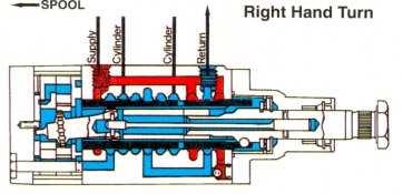
268 STEERING SYSTEM L 2
269 STEERING SYSTEM STEERING SYSTEM (HYDROSTATIC) POWER ASSISTED STEERING PUMP, RESERVOIR AND PIPES 1. DESCRIPTION AND OPERATION The power steering pump is mounted on the left hand side of the engine and is gear driven from the engine timing gears, at crankshaft speed. Two spur gears, Figure 1, produce oil flow for the operation of the power steering and are mounted in specially designed bearing blocks which are a precision fit in the pump housing. Figure 1 Power Assisted Steering Pump Components 1. Reservoir 2. Pressure Relief Valve Assembly 3. Pump Body - Rear 4. Bearing Block 5. Pump Body 6. Drive Gear 7. Pump Body - Front 8. Sealing Rings 9. Pump Gears 10.Filter Elements L 3
270 STEERING SYSTEM The Pump driving gear and shaft are integral. The front of the shaft protrudes through the pump front cover plate and is suitably tapered to accept the external drive gear. The external drive gear meshes with the engine camshaft drive gear so that whenever the engine is running the pump is in operation. Rotation of the pump gears draws oil from the reservoir mounted directly on the rear of the pump body. On entering the pump, the oil fills the gear tooth spaces and is carried around the housing, by the closely fitting gears, to the point where the teeth in the two gears come into mesh. The oil is then thrust out from between the teeth and delivered through an outlet port in the pump body to the pump outlet elbow. The oil on return passes through a paper element filter incorporated into the reservoir. When the tractor steering gear is held in the full lock position or the front wheels are agaisnt an obstacle, the pressure in the system will increase as the pump continues to deliver oil. When the oil reaches sufficient pressure, see "Specifications", the pressure relief valve lifts from the seat and the pump oil flows through a drilling into the reservoir. The pressure relief valve is located in the pump rear cover and is accessible after removing the reservoir casing, Figure 2. NOTE: The steering should not be held in the full lock position, or with the front wheels against an obstacle, for more than 30 seconds as damage to the system can result. 2. POWER STEERING PUMP-OVERHAUL REMOVAL 1. Support a suitable clean container under the pump and reservoir assembly. 2. Disconnect the pump pressure and return pipes and allow the oil to drain. 3. Plug the two disconnected pipes and ports to prevent the entry of dirt. Figure 2 Power Steering Pump Installation 1. Pump Return Pipe 2. Reservoir Retaining Bolt 3. Pump Pressure Pipe 4. Extract the two bolts retaining the pump front flange in the timing gear casing. 5. Remove the pump assembly from the tractor and drain the remaining oil from the reservoir. DISASSEMBLY 1. Remove the reservoir retaining bolt and pull of the reservoir casing. Discard the large "O" ring seal and filter element. 2. Straighten the tap on the lock washer locating the drive gear retaining nut. 3. Undo the nut and remove the washer. Use Puller, EF-0501 to withdraw the drive gear. 4. Remove the key from the drive gear shaft. 5. Withdraw the pressure relief valve from the pump body. 6. Remove the four bolts and separate the front and rear end covers from the pump body. L 4
271 STEERING SYSTEM Figure 3 Pump Gears and Blocks Removed 1. Bearing Blocks 2. Pump Gears 3. Pump Body Figure 4 Gear Track in Body 1. Inlet Side 2. Bore Diameter 3. Outlet Side 4. Depth of Gear Track 7. Noting their positions relative to the pump body for re-assembly, remove the bearing blocks and pump gear, Figure Remove the snap ring retaining the drive shaft oil seal in the front end cover and extract the oil seal. 3. Inspect teh bearing blocks, Figure 5, for signs of seizure or scoring. Light scoring on the sides can be removed by careful lapping on a surface plate using "O" grade emery paper and paraffin (Kerosene), ensure such parts are thoroughly washed and dried prior to reassembly. Should the wear be excessive install new bearing blocks. INSPECTION AND REPAIR 1. Clean all parts in a suitable solvent and air dry. Lightly oil machined surfaces. 2. Examine the pump body and gears for wear or damage. The wear track on the inlet side of the pump body interior should be free from scoring and no deeper than in. (0.065 mm.) Figure 4. The pump gears should not be scored or pitted. The pump body and gears are not supplied for service, if they are excessively worn a complete replacement pump must be installed. Figure 5 Pump Gears and Bearing Blocks 1. Drive Gear 2. Bearing 3. Driven Gear 4. Bearing Block L 5
272 STEERING SYSTEM Figure 6 Steering Pump Pressure Relief Valve 1. Valve Head 5. Valve Seat 2. Shims 6. "O" Ring 3. Pin 7. Valve 4. Seal 8. Spring Figure 4 Gear Track in Body 1. Inlet Side 2. Bore Diameter 3. Outlet Side 4. Depth of Gear Track 4. Use the soft jaws of a vice to grip the seat of the pump pressure relief valve then unscrew the head and body. Check the components for wear or swarf contamination, Figure 6. RE-ASSEMBLY Re-assembly of the power steering pump follows the disassembly procedure in reverse. On re-assembly observe the follwing requirement: All rubber seals, "O" rings and the drive shaft oil seal must be replced. Ensure correct installation of the bearing blocks and seals, Figure 7. Tighten the four through bolts evenly and to the correct torque, see "Specification". Install a new lock washer under the pump drive gear retaining nut. Tighten the nut to the correct torque see "Specifications", and secure with the lock washer tab. Pour a small quantity of clean oil into the pump for initial lubrication and ensure the pump drive gear can be turned by hand. Install a new oil filter element. INSTALLATION Installation of the power steering pump follows the removal procedure in reverse. On installation observe the following requirements: Fill the power steering reservoir with the correct grade and quantity of oil, see "Specifications". Operate the steering from lock-to-lock several times to expel any air from the system and recheck the oil level. L 6
273 STEERING SYSTEM Figure 8 Pump Pressure Test Installation 1. Pressure Gauge, Tool No. EF Adaptor, Tool No. EF Output Elbow Figure 9 Pressure Relief Valve 1. Shims 2. Spring 3. Valve 4. Valve Seat 3. POWER STEERING PUMP-PRESSURE TESTING 1. Disconnect the pump pressure pipe at the elbow. 2. Connect Adaptor, Toll No. EF-1401 and Pressure Gauge, Tool No. EF-1400, to the output elbow, Figure Start the engine and obtain a reading on the gauge for the pump relief valve setting. Refer to "Specifications" for the correct setting. WARNING: Operate the engine just long enough to obtain an accurate reading. Prolonged operation will cause overheating and damage. 4. If the setting is incorrect remove the relief valve and adjust the shims as follows: (i) With a suitable container held under the pump assembly, disconnect the return pipe. (ii) Remove the reservoir casing and carefully drain the oil. (iii) Extract the pressure relief valve, Figure 9. (iv) Use the soft jaws of a vice to grip the seat of the pressure relief valve then unscrew the head and body. (v) Carefully withdraw the pressure relief valve head, guide, seal and spring and add or subtract shims as required. NOTE: For every 0.01 in. (0.25 mm.) increase in shim thickness, the pressure relief valve setting is increased by 100 lbf/in 2 (6.9 bar) (7.0 kgf/cm 2 ). L 7
274 STEERING SYSTEM (vi) Re-assemble and replace the pressure relief valve and reservoir. Re-check the pressure setting. 5. When the adjustment is correct, remove the pressure test equipment and re-install the pump pressure pipe. 6. Fill the reservoir with the correct grade and quantity of oil, see "Specifications". Turn the steering from lock-to-lock several times with the engine running to expel any air from the system then re-check the oil level. Do not mix. oil grades. 4. RESERVOIR FILTER AND HYDRAULIC PIPES TO RENEW FILTER ELEMENT 1. Hold a suitable container under the pump assembly then disconnect the pressure and return pipes and allow the oil to drain. 2. Extract the reservoir retaining bolt, ease the reservoir casing away from teh pump body and drain off any remaining oil. 3. Discard the old filter element. 4. Clean the reservoir casing with a suitable solvent and dry with a lint-free cloth. 5. Inspect the large reservoir sealing ring and retaining bolt sealing washer for damage and replace if necessary. 6. Install a new filter element and replace the reservoir. 7. Re-connect the power steering pump pressure and return pipes. Figure 10 Hydrostatic Steering Oil Filter 1. Filter 2. "O" Ring 8. Fill the reservoir with the correct grade and quantity of oil, see "Specifications". 9. Operate the steering from lock-to-lock several times with the engine running to expel any air from teh system then re-check the oil level. HYDRAULIC PIPES 1. Inspect the hydraulic pipes for leakage at connections. Replace oil seals (where fitted) and tighten loose connections. 2. Check the pipes for signs of tracture and re-new if necessary. 3. Examine flexible hoses for cracks or chafing and renew if required. 4. Ensure the anti-vibrations clamps are correctly installed as shown in Figure 10. L 8
275 STEERING SYSTEM STEERING SYSTEM (HYDROSTATIC STEERING) 1. DESCRIPTION AND OPERATION The Farmtrac-60 feature an hydraulic power assisted, hydrostatic steering system. The components are serviced separately and consist of the steering column shaft, steering motor, front steering cylinder, power steering pump and reservoir, and the hoses and tubes required to connect the system. STEERING MOTOR CONTROL VALVE SECTION With reference to Figure 1. The control valve section directs the hydraulic oil to and from the metering unit, to and from the front steering cylinder and also regulates the pressure of the oil flowing to the front steering cylinder. The lower end of the input shaft is bored to receive the top of the torsion bar. The torsion bar is pinned to the input shaft, extends through the spool and is linked with the drive link in the emetering system. The integral power steering pump and reservoir are mounted on the rear of the engine front cover plate at the left-hand side of the engine. The pump and reservoir are connected to the steering motor by two oil tubes. The steering wheel is secured to the steering column shaft. The steering column upper shaft is joined to the power steering motor input shaft by a coupling secured with a pinch bolt. The power steering motor and steering column assembly are mounted on a housing bracket which is bolted at the transmission housing. The hydrostatic steering motor uses a linear control valve to control the direction of the steered wheels and a metering unit to control the rate of turn. In the event of pump failure the metering unit functions as an hydraulic pump and the wheels can be turned manually. Figure 1 Steering Motor Control Valve Section 1. Drive Ring 6. Valve Housing 2. Spacer 7. Spool 3. Input Shaft 8. Retainer Ring 4. Pin 9. Torsion Bar 5. Actuating Ball L 9
276 STEERING SYSTEM PUMP METERING SYSTEM With reference to Figure 2. The metering system meters oil to the steering cylinder and maintains the relationship between the steering wheel and the front wheels. The metering system also acts as a manually operated hydraulic pump in the event of power steering pump failure. Figure 2 Steering Motor Metering System 1. Spacer 2. Drive Link 3. Commutator 4. End Cover 5. Commutator Ring 6. Manifold 7. Rotor and Stator Assembly The drive link is splined to, and truns the rotor of, the rotor and stator assembly. The torsion bar is the principal link between the input shaft and the metering system in the power steering mode of operation. The lower end of the input shaft is splined to engage the drive ring. The drive ring is externally splined to engage and drive the spool. The drive ring splines are wider than those on the input shaft to allow a predetermined amount of free-play. This design provides a mechanical link between the shaft and spool for manual steering in the event of pump failure and limits the amount of twist on the torsion bar. A helical groove is machined in the side of the input shaft and the actuating ball is held captive between the helical groove and a pocket inside the spool. When the steering wheel is turned the torsion bar twists and moves the spool up or down to uncover oil ports leading to the metering system. As the spool moves up or down from the neutral position, the oil flow to the return line is restricted and causes the pump pressure to rise. Simultaneously, the flow is directed to the metering rotor assembly through the manifold and commutator. The oil flows from the metering rotor assembly to one side of the front steering cylinder whilst oil flows back into the system from the opposing side of the cylinder. Oil flow through the metering rotor assembly causes the rotor to rotate. The rotor is keyed to the spool by the drive link and rotation causes the spool to react against a helix and move towards the neutral position. A feedback is thus provided so that as the steering wheel is turned, the steering cylinder movement is measured and the spool is neutralised after the cylinder has moved the required amount. STEERING CYLINDER The double acting steering cylinder is transversely mounted on the front axle. The cylinder end of the assembly is bolted to an adjuster bar which forms an integral part of the front axle assembly and facilitates re-positioning of the cylinder when adjusting the track setting. The rod end is attached to the left-hand spindle arm which is connected by the track rod to the righthand spindle arm. The cylinder incorporates a piston centrally mounted on the piston rod. This arrangement enables the piston to present surfaces of equal area to the operating oil and the resultant forces ensure similar right and lefthand turning circles. L 10

277 STEERING SYSTEM Figure 3 Hydrostatic Steering Pipes 1. Flexible Hoses 2. Rigid Pipes Figure 4 Steering Motor Removal 2. HYDROSTATIC STEERING SYSTEMOVERHAUL STEERING MOTOR REMOVAL 1. Disconnect the battery ground cable at the battery. 7. Remove the four bolts retaining the steering motor support bracket. 8. Slacken clamp bolt securing the steering column to the motor and carefully withdraw the motor assembly from the left-hand side of the tractor, Figure Clean the flexible steering hose to rigid pipe connections, Figure With a suitable container positioned to store the escaping steering oil, mark and separate the flexible steering hoses from the rigid pipes. Cap and seal the pipes, using suitable plugs. 4. Slacken the retainer bolts securing the pipes to the side of the engine. 5. Unclip and separate the throttle connecting rod from the pedal linkage. 6. Withdraw the four retaining screws and remove the loser steering column shroud by withdrawing main harness connector to gain access to the steering column to motor coupling. Figure 4. Figure 5 Steering column to Motor Connection 1. Clamp Bolt 2. Steering Column. 3. Steering Motor L 11
278 STEERING SYSTEM SEAL REPLACEMENT INSTRUCTIONS NOTE: Follow the Instruction and do not disasssemble the steering unit upper cover; to replace the shaft, seal. 1. Remove the dirt seal over the end of the steering unit upper cover, if applicable. Discard this part. 2. Remove the retaining ring do not discard, this part must be reinstalled during assembly procedure. 3. To remove the seal package parts from the steering unit plug three of the four ports in the steering unit and pressurize the other port with air pressure to force the seal package out. Discard these parts. NOTE: Clean the steering unit input shaft and upper cover seal bore to remove particle of dirt, felt, lint, etc. with a clean, lint-free rag. CAUTION: Excessive particle of felt or lint can cause the new seal package to leak. 4. Cover the end of the steering unit input shaft with cellophane tape to protect the new seal when it is assembled over the sharp edges of the input shaft. 5. Lubricate the new seal using hydraulic oil and install the new seal with lip side first, onto the steering unit input shaft. 6. Remove the cellophane tape from the steering unit input shaft. 7. Assemble the new washer, with small end first, onto the steering unit input shaft and push the new washer and the new seal, previously installed, down into the steering unit uupper cover. Short piece of metal tubing 15/16 minimum I.D. x 1-3/ 16 maximum O.D. or a 7/ 8 deep well socket may be used to push these parts into place. 8. Assemble the previously used retaining ring onto the steering unit input shaft and down into the steering unit upper cover groove. Be sure the rounded edge of the retaining ring is faced inward. 9. Assemble the new seal onto the steering unit input shaft and down into the steering unit upper cover counter bore. DISASSEMBLY Cleanliness in servicing the power steering system is imperative. If it is necessary to disassemble any of the units, ensure a clean work bench or table is used. Clean off external dirt before the unit is placed on the work bench. When disassembled, parts should be cleaned only in clear-clean petroleum base solvent and blown dry with clean air. Other solvents may cause deterioration of rubber seals. Avoid wiping parts with cloth and never steam clean hydraulic steering assemblies. NOTE: The spool and housing, the commutator and commutator ring and the rotor and stator are selectively fitted and must be serviced as follows: If the spool or housing must be replaced, replace the complete motor. If the commutator or commutator ring must be replaced, replace both as a matched set. If the rotor or stator must be replaced, replace the complete metering element. If the pin in the end cover or the end cover must be replaced, replace the pin and end cover assembly. Refer to Figure 6 for identification of parts during disassembly and re-assembly. Plug the four port holes and clean the exterior of the steering unit throughly. Then remove the plugs. 1. To prevent possible distortion or damage to unit if placed directly in vice, the following procedure should be used. Insert O ring tube fitting, with tube nut or fitting cap attached, into one of the four threaded ports in the housing. Clamp the fitting in a vice in a manner, which will locate the L 12
279 STEERING SYSTEM 1. Thrust Washer 2. Snap Ring 3. Shims 4. Valve Thrust Bearing 5. Thrust Washer 6. Pin 7. Dirt Seal 8. Snap Ring 9. Input Shaft 10. Back-up Washer 11. Packing Seal 12. Cover Screw 13. Upper Cover Assembly 14. Seal 15. Drive Ring 16. Spacer 17. Torsion Bar 18. Steel Ball 19. Plug (where fitted) Figure 6 Steering Motor 20. 'O' Ring (where fitted) 21. Steel Ball (where fitted) 22. Housing 23. Valve Spool 24. Spool Ball Retainer Spring 25. Bolt 26. End Cover 27. Washer 28. Rotor Seal 29. Seal Retainer 30. Commutator 31. Commutator Ring 32. Manifold 33. Metering Element Rotor 34. Metering Element Stator 35. Drive Link 36. Spacer 37. Spacer 38. Spring Washer L 13
280 STEERING SYSTEM Figure 7 Power Steering Motor 1. Tube Fitting 2. Vice seven end cover bolts in an upright position. Figure Unscrew the seven special bolts from the end cover. NOTE: Special care should be used in the following steps to insure protection of the gound and lapped faces of the componenets. A void scratching or nicking of finished surfaces. 3. Remove end cover by bumping it sideways with a soft hammer to loosen it from the rotor seal and seal retainer, and lift from unit. CAUTION: The washer and commutator may adhere to the end cover, and may be removedwith the end cover. Do not attempt to remove pin because pin is press fit in the plate and is non serviceable. Figure Remove the rotor seal and seal retainer by bumping the sideways with a soft hammer to loosen it from the housing and lift off the rotor seal and seal retainer. Discard the rotor seal. 5. If the wear washer and commutator were not removed with the end cover, remove these parts from the steering unit. 6. Remove the commutator ring from the manifold, Figure 8 Commutator Removal 1. Cummutator Ring 3. Metering Section 2. Manifold 4. Commutator by a sliding and lifting motion. Care should be used in the handling of this fragile component. 7. Remove the manifold from the rotor set by sliding and lifting motion. 8. Remove the rotor set spacer and drive link as an assembly by grasping the spacer and removing the assembly with a sliding and lifting motion. Figure 9. Figure 9 Metering Element Removal 1. Metering Element 2. Spacer L 14
281 STEERING SYSTEM Figure 7 Power Steering Motor 1. Tube Fitting 2. Vice Figure 8 Commutator Removal 1. Cummutator Ring 3. Metering Section 2. Manifold 4. Commutator 9. Separate drive link by sliding the rotor set on the spacer, allowing the drive link teeth to clear the spacer hole. Remove drive link and separate rotor set from spacer. Use extreme caution to keep vanes and springs from failing out. When handling the rotor set, pressure should be applied to the rotor by gripping the rotor set between the fingers and urging the rotor into contact with the stator. Figure 10. Carefully protect against damage to side faces. NOTE: The rotor and the stator must be kept in a matched set. 10. Reverse the steering unit in the vice to place the input shaft in a vertical position. Using a prick or centre punch, mark the upper cover flange in relation to a similar mark placed on the port face of the housing to facilitate reassembly. Figure Remove the four special cap screws by using a 5/16-12 point socket. 12. Grasp the input shaft and with a smooth upward motion, remove the input shaft, upper cover and spool assembly from the housing. NOTE: A void applying side forces to the spool which would cause binding of the closely fitted assembly. Never use excessive force to remove the spool from the housing. 13. Remove and discard seal. 14. Remove the upper cover with shaft seal package intact. Remove spacer item. 15. Remove shims from either upper cover cavity or from face of thrust washer. Count and record the number of shims to aid in reassembly of unit. 16. Remove seal, retaining ring, using proper snap ring pliers. Discard seal. Remove and discard backup washer. Remove and discard seal. 17. Remove the retaining ring, thrust washer, thrust bearing, thrust washer and spring washer from input shaft. NOTE: Retaining ring is twisted design. Do not straighten ring. L 15
282 STEERING SYSTEM Figure 12 Steering Motor Input Shaft and Spool 1. Spool 2. Input Shaft 18. Remove the needle roller by using a pin punch of in. (3 mm) max. diameter for a minimum of in. (16 mm) length. The input shaft should be placed on a block of wood (to avoid shaft damage) and the needle roller removed by impact, using light hammer blows. Figure Remove the torsion bar and spacer by inverting the spool assembly and allowing the parts to fall free. Do not remove needle roller from torsion bar. Figure Remove the drive ring by placing the end of the spool on a table surface. Rotate the input shaft to extremes of travel unitl the drive ring falls free. Figure With the spool assembly in the same position as the step above, rotate the input shaft in a clockwise direction unitl the actuator ball disengages from the helical groove in the input shaft. Lift out input shaft. CAUTION: The actuator ball may fall free and care should be used to not lose it. 22. Do not remove the ball retainer spring unless replacement is required. If necessary to remove this spring, discard the retainer if moved. A screwdriver may be used to assist in the prying of the spring over the shoulder of the spool. Care must be used to avoid scratching or nicking of Figure 13 Torsion Bar and Spool 1. Spool 2. Torsion Bar the spool outside diameter and control edges. The followng provedure is optional. 23. Return to the housing which is mounted in the vice. Remove the plug and roll pin assembly. A steel ball is captivated by the plug and roll pin assembly. Care must be used to avoid the loss of the ball. Remove ball by shaking after housing is removed from the vice. Discard O ring. This completes the disassembly of the steering unit. Figure 14 Drive Ring Removal 1. Spool 2. Drive Ring L 16
283 STEERING SYSTEM INSPECTION AND REPLACEMENT Visually inspect all parts and replace those parts which are not in good condition. The followng finished surfaces should be inspected for abnormal wear, scroing or damage. 1. Housing bore and ends. 2. Valve spool outside diameter, Some burnishing due to use may be observed. 3. Valve spool control edges. 4. Valve spool splines. 5. Input shaft seal area. Check for rust, pitting and excessive wear. Light circumferential polishing due to seal contact may be observed. 6. Input shaft helical groove. Note the contact pattern created by the actuator ball. Surface should be free from pits chipping or surface break down. 7. Thrust bearing and thrust washers. Inspect for pitting of rolls and faces of thrust washers. 8. Drive link pin slot. Width of slot must not exceed in. difference at any point in its length. 9. Drive link teeth. 10. Torsion bar and needlle roller assembly. Difference in diameter of needle roller should not in. The following parts may show a polish pattern due to the rotor action and the circular motion of the commutator. The sides of these components are ground and lapped and should be free from nicks, burrs and scroing. 1. Spacer 2. Manifold 3. Rotor 4. Commutator and Commutator Ring NOTE: Thickness difference between commutator and commutator ring shall not exceed in. 5. End cover and pin assembly. NOTE: The rotor set requires special attention in handling to avoid nicks and scratching. It is recommended that the rotor, stator, vanes and springs be checked in the assembled condition. To inspect the rotor set, place the Figure 15 Metering Element 1. Rotor 2. Stator 3. Vane Spring 4. Vane assembly face down on the lapped face of the end cover and check for freedom of rotor rotation within the stator. The action of the spring loaded vanes may be observed during rotation. The vanes should move freely in their slots, without bind, due to the forces of the springs. Figure 15. Using a feeler gauge, check the rotor to the stator clearance as shown in Figure 16. If there is more than a in. clearance, the rotor set must be replaced. Figure 16 Rotor to Stator Check 1. Rotor 2. Stator 3. Feeler Gauge L 17
284 STEERING SYSTEM NOTE: This applies to rotor sets with and without vanes. Carefully lift the rotor set assembly from the end cover and measure the thickness of the rotor and stator. Thickness difference between the rotor and stator shall not exceed in. (0.05 mm). The internal splines in the rotor should not allow abnromal wear or damage. ASSEMBLY PROCEDURE IMPORTANT: Before starting assembly, clean all parts wth clean petroleum base solvent and air dry. Do not wipe dry with rages. Be sure all dried paint chips have been removed from edges of lapped surfaces. Unless otherwise indicated, DO NOT oil parts before assembly. 1. Insert ball into its cavity in the housing. 2. Install new O ring on plug and roll-pin assembly and install in the housing. Tighten to the correct torque, see Specifications. 3. Re-clamp housing in the vice as shown in Figure Assemble thrust washer, thrust bearing, thrust washer and retaining ring on input shaft. 5. If the retaining spring has been removed, install a new retaining spring. The spring must fit tightly. 6. Insert actuator ball into ball seat located inside spool. 7. Assemble wave spring washer over thrust washer and thrust bearing. Insert the input shaft into the spool, engaging the helix and ball with a counterclockwise motion. This operation is best done while holding the Spool in a horizontal position. 8. Using the mid-section of the torsion bar as a gauge, insert the gauge between the spool end and the thrust washer. Figure 17. This will position the spool in the necessary radial relationship with the input shaft spline teeth for assembly of drive ring. 9. Place the input shaft and spool assembly in a vertical position, with the shaft end on the table surface. NOTE: Rotate the input shaft out of the valve spool until input shaft will no longer rotate. There Figure 17 Steering Motor Upper Cover 1. Mandrel 2. Upper Cover will be a gap of approximately in. (8.89 mm) between end of valve spool and thrust washer if the drive ring is assembled properly. 10. Insert the drive ring into the spool end by visually aligning an internal space on the drive ring with a tooth on the input shaft spline, and allow the drive ring to drop to the limit of its travel. If the drive ring does not engage the input shaft spline, a slight rotation of the input shaft will allow the drive ring to become fully engaged. Remove torsion bar gauge. Figure 18. Figure 18 Using Torsion Bar as a Gauge 1. Spool 2. Torsion Bar 3. Thrust Washer L 18
285 STEERING SYSTEM Figure 19 Pressing Pin into Input Shaft 1. Press Arbor 2. Input Shaft CAUTION: The steering will not function properly if the correct relationship of spool, drive ring and input shaft is not achieved. 11. Install spacer over torsion bar and pin assembly and insert the assembly into the spool end. 12. Align the cross-hole in the torsion bar with the cross-hole in the input shaft and insert a in. (3 mm) diameter pin punch to maintain alignment. 13. Insert the needle roller into cross-hole in input shaft; and while retracting the pin punch, engage the pin in the torsion bar cross-hole. 14. Press the pin flush with the outside diameter of the input shaft, Figure 19. With a few light taps on the 0.12 in. (3 mm) diameter pin punch, drive the pin approximately 0.03 in. (0.76 mm) below the input shaft outside diameter. 15. Assemble spacer over valve spool against spring washer. If so constructed the inside lipend of spacer must be toward the spring washer. Place assembly, spool end first, into housing. CAUTION: A void applying side forces to the spool which would cause binding of the closely fitted assembly. 16. If neither the input shaft or upper cover are replaced, the original shims may be reused. If the shims are damaged, replace with shims of the same thickness. Figure 20 Upper Cover Installation 1. Upper Cover 2. Hose Clamp Place shims on top of the thrust washer. Coat seal with clean grease and place in upper cover counterbore. Assemble upper cover on to input shaft and rotate to align punch marks previously made during disassembly. NOTE: If a new upper cover is used then no angual alignment is required. However, it is necessary to align the upper cover and housing. 17. Install the upper cover screws finger tight. Use a pilot ring, or a worm drive type hose clamp tightened around the upper cover flange and the body pilot diameter, to achieve the required alignment, Figure 20. Tighten the screws to the correct torque, see Specifications. NOTE: If any of the input shaft housing and spool torsion bar or upper cover have been replaced, the following procedure for checking and shim adjustment must be used. 18. Conduct the shimming procedure as follows: After torquing the four screws revolve the unit in vise so that the input shaft is pointing downwards. In order to determine that the unit is shimmed correctly, the drive link must be in its proper position, To do this, grasp the input shaft pull down ward, and prevent rotation. Engage drive link splines in spool and rotate to postion spool essentially flush with end of housing. Remove drive link and orient drive link slot to engage L 19
286 STEERING SYSTEM Figure 21 Shimming on Final Assembly 1. Drive Link 2. Straight Edge 3. Feeler Gauge 4. Spool torsion bar needle roller and insert drive link. Observe relationship of spool end to the body. The valve spool must protrude [0.20 in. ± in.] from the adjacent counterbore surface. If within spac. no additional shimming required. If not within in. add or remove shims until this requirement is satisfaied repeating assembling steps as outlined above. With reference to Figure 21. The correct shimming must be checked on the vehicle or on a suitable hydraulic test sand. The amount of steering effort required to steer the vechicle when the vehicle is at rest on dry payment must be equal within two inch pounds. For example if twenty-one inch pounds is required to steer to the right, not less than thirteern or more than twenty-three inch ponds should be required to steer to the left. If a test stand is available to place a load between cylinder ports in the same manner as on the vehicle, a test stand should be used. Add shims to increase steering efforts in a left turn, subtract shims to increase steering effort in a right turn. 19. With the drive link installed as described above, assemble two assembly posts into the housing as shown Figure 22. These assembly posts can be made by simply cutting the heads off of two bolts similar to the special bolts. Figure 22 Spacer Installation 1. Assembly Posts 2. Spacer 20. Assemble space plate over assembly posts and onto housing with plain side up. 21. Install rotor seat over assembly posts and onto spacer plate. NOTE: One of the seven holes in the rotor set may be smaller than the other six holes. Position this, hole, if applicable, over one of the assembly posts. Reference Figure 23. Figure 23 Metering Element Installation 1. Rotor 2. Stator 3. Drive Link L 20
287 STEERING SYSTEM Figure 24 Manifold Installation 1. Assembly Posts 2. Manifold Figure 25 Commutator Ring 1. Slot 2. Manifold WARNING: All vane springs must be down in their slots with no part of spring protruding out either side of metering element. 22. Install manifold over assembly posts and onto rotor set, make sure circular slot side of manifold is up. With reference Figure Install commutator ring over assembly posts and onto manifold make sure slot side is down. Reference Figure Install five of the special bolts finger tight. Remove two assembly posts and assemble the other two special bolts finger tight. WARNING: Finish tightening the seven special bolts according to the following procedure. Do not over-tighten as irrepairable damage will occur. 24. To allow for washer assemble commutator with counterbore up into commutator ring with slotted hole in commutator engaging nose of drive link. Align commutator outside diameter concentric with inside diameter of commutator ring. With reference Figure Install rotor seal and seal retainer over rotor set and down against housing. 26. Apply a small amount of clean grease to washer and install over pin in the end cover the assembly. Grease should hold washer to the end cover assembly. 27. Assemble the end cover assembly with washer attached, over assembly posts and onto the steering motor. Figure 26 Commutator Installation 1. Commutator Ring 2. Commutator L 21
288 STEERING SYSTEM Figure 27 Steering Motor End Cover Bolt Tightening Sequence 1. Torque all seven special bolts to 2-3 ft. lbs. in sequence as shown in Figure Torque all seven special bolts to ft.lbs. in sequence as shown in Figure 27. NOTE: Rotate input shaft during step 2 to prevent binding. 29. Relocate unit in a vice with the input shaft upwards. Cover end of input shaft with cellophane tape, to protect new seal when it is assembled over sharp edges of input shaft. 30. Lubricate and install new seal with lip side first onto input shaft. 31. Assemble new washer, with small end first, onto input shaft and push new washer and new seal down into upper cover. (A short piece of metal tubing. 15/16 in. minimum I.D. x 1-3/16 in. maximum O.D. or a 7/8 in. deep well socket may be used to push these parts into place.) 32. Assemble retaining ring into upper cover groove. Be sure rounded edge of retaining ring is faced inward. 33. Assemble new dirt seal into upper cover counterbore. NOTE: If the unit is the be stored, plug the cylinder ports and fill the inlet port with clean oil. Rotate input shaft until oil appears at outlet port. 34. Plug the port holes to prevent entrance of dirt. This completes asseembly of the unit. Figure 28 Steering Cylinder and Anchor 1. Anchor 2. Cylinder Assembly Retaining Nut 3. Feed Hose Support Bracket 4. Rod End Assembly INSTALLATION Installation of the steering motor assembly follows the rmoval procedure in reverse. On installation observe the following requirements: Tighten all nuts, bolts and connections to the correct torques, see Specifications. Purge the air from the system by starting the engine and turning the front wheels from lock-tolock several times. If necessary, add oil to the reservoir. Repeat until steering is normal and the oil level in the reservoir remains constant. For the correct grade and quantity of oil see Specifications. HYDROSTATIC STEERING SYSTEM CYLINDER OVERHAUL REMOVAL AND DISSASSEMBl Y 1. Disconnect the two oil feed pipes from the power cylinders. Cap the pipe ends. 2. Unscrew the ball stud nuts. 3. Remove the power cylinder assembly from the tractor. 4. Loosen the clamp retaining the ball end to the piston rod and unscew the ball end assembly. 5. Remove the piston rod bush retaining snap ring and remove the scraper, outer seal, retainer and inner seal. Figure 28. L 22
289 STEERING SYSTEM NOTE: The power cylinder assembly cannot be further dismantled and if faulty, must be replaced as a unit. RE-ASSEMBlY AND INSTALLATION Re-assembly and installation follows the disassembly and removal procedures in reverse. On installation observe the following requirements. Tighten all nuts to the correct torque, see Specifications. Fill the power steering reservoir with the correct grade and quantity of oil, see specifications. Operate the Steering several times with the engine running to expel all air from the system then recheck the oil level. WARNING: All vane springs must be down in their WARNING: Do not mix oil types any mixture or an unapproved oil, could deteriorate the seals. Enough fluid could then leak to create a loss of power steering assists. Do not allow fluid level to go below fill line on dipstick. Before adding new fluid, completely drain old oil from the system. It may be necessary also that you flush the system with clean oil. L 23
290 SECTION - 'M' FRONT AXLE (Mechanical Steering) S.NO. CONTENTS PAGE 1. DESCRIPTION M ADJUSTMENTS M FRONT WHEEL HUB & SPINDLE OVERHAUL (FT-60) M FRONT WHEEL BEARING ADJUSTMENT M FRONT AXLE & SUPPORT OVERHAUL (FT-60) M END-FLOAT ADJUSTMENT PROCEDURE (FT-60) M SPECIFICATIONS M - 7
291 FRONT AXLE M 2
292 FRONT AXLE FRONT AXLE (Mechanical Steering) 1. DESCRIPTION AND OPERATION In Farmtrac-60, the front axle consists of an inverted U section centre beam that is mounted centrally to the front axle support by an axle support pin. The front axle radius rod is not provided in Farmtrac-60. The front axle is having the benefit of additional seals to make it water proof. The axle support pin ends have sleeves shrink fitted onto the two ends. The sleeves run into support bushes. Both ends have grease pockets in front, closed by plugs. The inner ends of the sleeve house O rings for grease retention and as a seal against water ingress. The wheel hub is supported on the wheel spindle by two opposed taper roller bearings. A nut on the spindle is used to retain the outer cone and roller assembly. This nut provides means of an adjustment for the bearing pre load.. 2. ADJUSTMENTS A. FRONT TRACK ADJUSTMENT FARMTRAC-60 The track of front axle for Farmtrac-60 is adjustable from 48 in. (122 cm.) to 76 in. (193 cm.). Refer to Figure 2 and the table given below for the track setting. The axle section of Farmtrac 60 consists of an inverted U section beam with a tube to accept the wheel spindle welded to outer end. The centre axle assembly and the axle sections are machined to provide a series of holes that will allow the track of axle to be varied in 4 in. (10cm.) from 48 in. (122 cm.) to 72 in. (183 cm.) The outer end of the axle sections accept the front wheel spindles. These spindles are located by bushings in the axle section and at the lower end a thrust bearing is used to support the vertical thrust of the spindle on the axle section. The spindle itself acts as the king pin and hence the king pin inclination remain constant in relation to the axle beam. The top of each wheel spindle has a key way to locate a steering arm, which is connected at the other end to the relative steering gear steering arm by means of a drag link. Figure 1 Front Axle Extension (left-hand side) 1. Securing Bolts 2. Centre Beam 3. Axle Outer Section M 3
293 FRONT AXLE Track Setting in. (cm.) 48 (122) 52 (132) 56 (142) 60 (152) 64 (163) 68 (173) 72* (183) 76* (193) * With wheels reversed. Axle bolt locations Refer to Figure 2 A B C D E F E F C D E F G H G H number of turns required. Turn the steering half the number of turns from either lock to give the mid point of steering movement. Position the wheels in the straight ahead position. Install the drag links into the steering gear arms without moving the steering gear from its determined mid point. Adjust the length of the drag links to obtain the specified toe-in. Mark the steering spindle arms and axle section with a chisel to indicate the correct position. 3. FRONT WHEEL HUB AND SPINDLE OVERHAUL FARMTRAC-60 NOTE: The front wheel discs are off-set relative to the center line of the rim. If the front wheels are reversed on the hubs the track settings will be increased by approximately 8 in (20 cm). The overhauling procedure for front wheel and hub for Farmtrac-60 with the following changes. B. TOE-IN ADJUSTMENT The toe-in of the front wheels may be adjusted to within the specified limits by adjusting the length of the drag links. The correct toe-in is set during the production of the tractor. The axle sections, and their respective steering spindle arms are marked to identify the correct position of the wheels, with the steering in the straight ahead position. If the new axle sections or steering spindle arms are installed it will be necessary to realign the wheels and mark the components for future reference. When the marking has been retained at one side of the tractor this mark is used as a reference to find the centre point of the steering. Adjust the length of the drag link of the side to be marked and to bring the wheel toeouter to within specifications. Mark the wheel spindle arm and axle sections with a chisel accordingly to indicate the correct position. Where it is not possible to use existing markings to determine the straight ahead position of the steering it will be necessary to find the centre point of steering gear movement. Disconnect the drag links from the steering gear arms. Turn the steering gear from lock to lock counting the Figure 2 Spindle and Hub Assembly 1. Upper Dust Seal 2. Upper Seal Assembly 3. Lower Seal Assembly 4. Spindle Seal 5. Double Lip Hub Seal 6. Bush 7. Loctite 8. Lower Dust Seal 9. Spindle Thrust Spacer 1. The steering spindle has been provided with upper and lower grease seals. An additional inner seal and thrust spacer are also provided on each spindle. Figure There is a double lip seal in place of the grease retainer. An additional cup is provided in the hub in which the seal runs. Replacement of the cup M 4
294 FRONT AXLE and seal will restore the assembly to 'as new' condition. 3. A layer of Locktite 577 is applied to the fillet corner prior to assembly of the spacer. When reassembling, ensure that the spindle and spacer surfaces are clean and dry prior to applying Locktite FRONT WHEEL BEARING ADJUSTMENT 1. After cleaning, pack the wheel hub and bearings with a suitable grease and install the wheel hub on the wheel spindle. 2. Install the front wheel outer bearing cone and roller assembly on the front wheel spindle. 3. Install the hub retaining washer on the wheel spindle, locating the tab with the key way in the spindle. 4. Install the wheel hub retaining nut. 5. Tighten the bearing retaining nut to a torque of lbf.ft. ( kgf.fm.). 6. Rotate the hub clockwise 3-6 revolutions. 7. Further tighten the retaining nut to a torque of lbf.ft. (6-7.6 kgf.m.). 8. Loosen the retaining nut by two slots. 9. Tighten the nut, if necessary, to the nearest position to allow insertion of a new retaining split pin. NOTE: Ensure that the wheel rotates freely without any drag. 5. FRONT AXLE AND SUPPORT OVERHAUL FARMTRAC-60 A. DISASSEMBLY 1. Remove the radiator as outlined earlier see SEPARATING THE TRACTOR 2. Support the tractor at the front end with a suitable jack or hoist. 3. Remove drag link front end assembly retaining nut and disconnect the drag links from their respective steering spindle arms. 4. Remove bolts and nuts retaining the axle sections to the centre axle assembly and remove the axle sections. 5. Remove 4 mounting bolts of bracket assembly trunnion and slide it out. Remove the front centre axle assembly from the front axle support. The front axle support pin for Farmtrac-60 is different from that for Farmtrac-50/55, as discussed below. a) The axle trunnion pins have sleeves shrink fitted onto both ends. The sleeves run in support bushes and house O rings at their inner ends for grease retention and sealing as shown in Figure 3. Replacing the sleeve and bushes will restore the assembly to as new position. b) Two grease nipples are provided, one on the front axle support and other on the trunnion, as shown in Figure 3. To enable the trunnion pin to be effectively greased, a screw in plug is provided in the centre of end covers. Remove the plug before greasing and apply a high pressure grease gun to the grease nipples until grease is expelled from the plug holes Reinstall the plugs after greasing. c) An additional thrust washer has been provided towards the rear of the trunnion pin. B. INSPECTION AND REPAIR 1. Inspect the bush bracket assembly trunnion and front axle support bush rear for excessive wear or scoring. If necessary, remove the bushing and inspect the bore in the bracket assembly and front axle support for damage. Install new bushings using step plate adapter. 2. Examine front axle support pin sleeves for excessive wear or scoring. If necessary, fit the new sleeves. As sleeves are shrink fitted on the front axle support pin, heat the sleeves to C to shrink onto the axle pin. 3. Examine the front axle support for fractures. To replace front axle support, remove the four bolts and nuts retaining the support to engine cylinder. M 5
295 FRONT AXLE Figure 3 Axle Trunnion Pin Assembly 1. Thrust Washer 2. Plug 3. Grease Nipple 4. "O" Ring 5. Sleeve 6. Grease Nipple 7. Plug 8. Grease Cavity 9. Trunnion Pin 10.Bush 11. Shim 12.Thrust Washer C. ASSEMBLY 1. Fit front axle support pin in the front axle support, install and tighten four mounting bolt of bracket assembly trunnion. 2. Check the end float of front axle support pin with feeler gauge. Add or remove shims to achieve required end float of in. 3. Install the axle extensions and retain them to the centre axle assembly with bolts and nuts and tighten to the specified torque. 4. Connect the drag links to their respective wheel spindle arms. 5. Remove the jack or hoist supporting the tractor. 6. Install the radiator and associated sheet metal. 6. END FLOAT ADJUSTING PROCEDURE FARMTRAC-60 Remove 4 mounting bolts of bracket assy; trunnion and slide it out. Add shims to achieve required end float of in. Check end float initially at 50 hours and then every 300 hours, adjust if required. For fitting the sleeves on front axle pins, heat the sleeves to a temperature of C. For removal of sleeves, heat the sleeves with welding torch and prime out by striking at O ring grooves. NOTE: To ensure proper sealing maintenance of end float is very essential. Excessive end float will cause water/mud ingress. Remove plug screw from end covers to allow the grease pressure to escape, refit plug screws use only UNIVAX A Grease. Greasing every 50 hours/weekly under normal conditions and daily in paddy operation is required after completion of days job work. M 6
296 FRONT AXLE 7. SPECIFICATIONS DESCRIPTION Wheel Track Adjustment in 4 in. (10.06 cm.) steps Axle articulation Camber angle Castor angle King Pin inclination Toe-in Truning Radius (with brakes) Truning Radius (without brakes) FARMTRAC in. (122 cm.) to 76 in. (193 cm.) to 0.5 in. (0-13 mm) 2.97 mt mt. SHIMS FT-60 Location Front axle support pin Thickness in in in. (0.05 mm) (0.13 mm) (0.38 mm) TORQUE SPECIFICATIONS Spindle Arm Clamping Bolt Axle Section Bolt Support Pin Bolts Radius Rod Foot Bolt Radius Rod Ball Cap Bolts Front Axle Support To Engine Drag Link Ball Pin Nuts Drag Link Adjusting Clamp Bolts Front Axle trunnion Bracket UNITS lbf.ft (kgf.m) lbf.ft (kgf.m) lbf.ft (kgf.m) lbf.ft (kgf.m) lbf.ft (kgf.m) lbf.ft (kgf.m) lbf.ft (kgf.m) lbf.ft (kgf.m) lbf.ft (kgf.m) FARMTRAC (6-7) (18-22) (19-22) ( ) ( ) 8-10 ( ) ( ) M 7
297 SECTION - 'N' FRONT AXLE (Hydrostatic Steering) S.NO. CONTENTS PAGE 1. DESCRIPTION N ADJUSTMENTS N FRONT WHEEL SPINDLE OVERHAUL (FT-60) N FRONT WHEEL BEARING ADJUSTMENT N FRONT AXLE & SUPPORT OVERHAUL (FT-60) N END-FLOAT ADJUSTMENT PROCEDURE (FT-60) N SPECIFICATIONS N - 10
298 FRONT AXLE N 2
299 FRONT AXLE FRONT AXLE (Hydrostatic Steering) 1. DESCRIPTION The three part front axle is an inverted U section beam which is mounted centrally to the front axle support. The support is bolted to the front of the engine cylinder block. The method of mounting consists of two support pins located on the same axis. The forward support pin is attached to the mid-point of the centre axle beam. The rear support pin is attached to the rear extension of the centre axle and locates in a bushing in the front axle support. The forward front axle support pin locates in a bushing incorporated in a bracket bolted to the front axle support. The method of mounting restricts the axle assembly to a radial movement about the support pin axis. The radial movement is limited by the front axle support. Outer axle sections, consisting of an inverted U section with a tube welded to the outer end to accept the wheel spindle, are installed into the open ends of the cenre axle assembly. The centre axle assembly and the axle sections are machined to provide a series of holes that will allow the track of the axle to be varied in 4 in. (10.2 cm) steps between 52 in. (122 cm) and 76 in. (193 cm). With reference to Figure 1. The left hand spindle arm is activated by the hydrostatic steering power cylinder and the movement is transmitted from the left-hand spindle to the right-hand spindle by means of a track rod, which is adjustable to suit various track settings. Figure 1 Front Axle Assembly N 3
300 FRONT AXLE Figure 2 Toe-in Alignment marks 1. Spindle Arm 2. Alignment Marks 3. Outer Axle Section Figure 3 Toe-in/Toe-out Measurement A. Dimension Between Wheel Rim Marks Toe-in/Toe-out of the front wheels may be adjusted by setting the length of the track rod. The correct toe-in setting is made during production and the spindle arms and axle sections are marked to identify the correct position of the front wheels with the steering in the straight ahead position, Figure ADJUSTMENTS TOE-IN MEASUREMENT If the toe-in alignment marks on the spindle arms and axle sections are not visible, or replacement parts have been installed use the following procedure to determine the toe-in setting. 1. On flat level ground slowly drive the tractor in a straight line for at least 10 feet (3 meters). Stop the tractor and ensure the front wheels remain in the straight ahead position. 2. Mark the inboard rim of each front wheel towards the front at wheel centre height. 3. Measure and note the distance between the two marks, call this dimesnion a, Figure Maintain the straight ahead position and move the tractor forward so the wheels rotate through 180 and the marks on the wheels face the rear at wheel centre height. 5. Again measure and note the distance between the two marks, call this dimension B. NOTE: If dimension A is larger, then A-B gives the toe-out. If dimension B is larger, then B-A gives the toe-in. To ensure accurate results, repeat the procedure three times with three different marks equally spaced around each wheel rim and determine the average dimesnion for toe-in/toe-out. This method minimises any inaccuracy due to wheel rim run-out. TOE-IN ADJUSTMENT 1. Set the front wheels in the straight ahead position using the alignment marks on the spindle arms and axle sections. If these marks cannot be used, position the wheels as described in the measurement section. N 4
301 FRONT AXLE Figure 4 Right-Hand Axle Assembly 1. Center sleeve 2. Center sleeve retaining bolts 3. Tie Rod end clamp 4. Tie Rod end 5. Arm steering spindle (LH) Figure 5 Left-Hand Axle Assembly 1. Track Rod Clamp Bolt 2. Track Rod Tube 2. Slacken the trac rod clamp bolt. Figure Remove the right-hand end of the track rod from the spindle arm. Figure Turn the track rod end to alter the length of the track until the toe-in marks on both the spindle arms and axle sections are aligned, when the right-hand end of the track rod and clamp bolt is re-installed. NOTE: If the alignment marks cannot be used, adjust the length of the track rod to obtain the correct toe-in. 5. Tighten the track-rod clamp bolts to the correct torque. 6. Re-check the toe-in. 7. If the alignment marks on the spindle arms and axle sections are missing, or out of alignment, lightly grind off this area and strike new marks. FRONT TRACK ADJUSTMENT NOTE: The track of the front axle is adjustable from 52 in. (132 cm) to 68 in. (173 cm). To obtain a front wheel track setting of 72 in. (183 cm) and 76 in. (193 cm). It is necessary to adjust the axle setting to a track of 64 in. (163 cm) and 68 in (173 cm). and reverse the disc of the front wheels to give required increase. It is not recommended that the wheels are reversed in 72 in. (183 cm) axle setting to obtain 80 in. (203 cm) wheel track as undue strain can be placed on components under high load and shock conditions. 1. With the tractor on firm level ground, apply the handbrake and chock the rear wheels. Use a suitable jack or hoist to raise the front wheels clear of the ground. 2. Remove the bolts and nuts retaining the axle outer sections and move the axle sections to the required positions. Reinstall the axle section N 5
302 FRONT AXLE Figure 6 Track Width Adjustment Holes retaining bolts and nuts in the appropriate holes as indicated in Figure 6 and the table below: Track Setting in. (cm.) 52 (132) 56 (143) 60 (153) 64 (163) 68 (173) 72* (183) 76* (193) * With wheels reversed. Axle bolt locations 3. Tighten the retaining bolts and nuts to the correct torque, see Specifications. 4. Position the front wheels straight ahead to align the toe-in marks on both the spindle arms and axle sections. 5. Remove the two clamp bolts on the track rod. Align the track rod clamps with the nearest notches and install the two clamps bolts. NOTE: Ensure an equal number ot notches are exposed at either end of the track rod tube. B C D E F E F D E F G H G H 6. Check and if necessary adjust, the Toe-in Alignment. 7. Remove the jack and wheel chocks. 3. FRONT WHEEL SPINDLE OVERHAUL FARMTRAC-60 A. DISASSEMBLY 1. Use a suitable jack or hoist to support the front end of the tractor. 2. Remove the six wheel retaining nuts and remove the wheel and tyre assembly. 3. Unscrew the front hub grease retaining cap. 4. Remove the cotter pin locating the castellated nut retaining the wheel hub. 5. Remove the nut and the hub retaining washer along with the hub & outer bearing. 6. Remove the inner bearing cone and roller assembly from the wheel spindle. Remove the grease retainer. 7. Remove the spindle bolt and nut retaining the steering spindle arm to the wheel spindle. 8. Remove the steering spindle arm from the wheel spindle. If arm is tight on the spindle use Tool Nos. EF 0800, EF 0501 and shaft protectors to remove. N 6
303 FRONT AXLE Figure 7 Installing Front Wheel Spindle Figure 8 Installing Front Wheel Inner Bearing 9. Extract the woodruff key from the spindle and remove the dust seal. 10. Extract the wheel spindle and thrust bearing from the axle extension. B. INSPECTION AND REPAIR 1. Clean components with a suitable solvent and air dry. Lightly lubricate machined surfaces. 2. Inspect roller bearing cones, rollers and cups for signs of excessive wear, or damage. Replace if necessary. Remove bearing cups from the wheel hub using Tool Nos. EF 0600 and EF Install new cups in hub, make sure that they are seated correctly against the shoulder. 3. Inspect spindle bushings in the axle extension housing for wear or scoring. If necessary to replace remove the axle extension from the tractor by removing the two retaining bolts and their associated nuts and lock washers. Remove the bushings making sure that the bores are not damaged and install new bushings in the bore. 4. Inspect the spindle thrust bearing for correct operation. Replace if necessary. 5. Inspect the wheel spindle bearing surfaces for scoring or excessive wear. C. ASSEMBLY 1. Pack the wheel spindle thrust bearing with grease and install on the wheel spindle. Make sure that the shroud is to the top, this is indicated on the bearing by the Manufacturer s reference stamped on this face, and in some instances the word Top. 2. Install the wheel spindle into the axle section housing, make sure that it rotates in the bushings freely. 3. Install a new wheel spindle dust seal with the groove in the periphery of the seal nearest the base Figure Install the woodruff key in the wheel spindle, Install the spindle steering arm on the wheel spindle located by the woodruff key. Make sure the arm to spindle bolt hole in the arm is in line with the recess in the wheel spindle. Install the arm to spindle bolt, lock-washer and nut and tighten to the specified torque. 5. Install the wheel hub grease retainer on the wheel spindle. 6. Install the front wheel inner bearing cone and roller assembly on the front wheel spindle, Figure Pack the wheel hub with a suitable grease. Install the wheel hub on the wheel spindle. 8. Install the front wheel outer bearing cone and roller assembly on the front wheel spindle. N 7
304 FRONT AXLE Figure 9 Spindle and Hub Assembly 1. Upper Dust Seal 2. Upper Seal Assembly 3. Lower Seal Assembly 4. Spindle Seal 5. Double Lip Hub Seal 6. Bush 7. Loctite 8. Lower Dust Seal 9. Spindle Thrust Spacer 9. Install the hub retaining washer on the wheel spindle. Locating the tab with the key way in the spindle. 10. Install the wheel hub retaining nut. 11. Install the wheel and tyre assembly on the hub and retain with the six nuts. 12. Tighten the slotted retaining nut to a torque of 45 to 55 Ibf. ft. (6 to 8 Kgfm.) and then slacken off 2 to 3 slots to give an end float of in. ( mm.). Install a new cotter pin to locate the nut. Install the hub grease retaining cap. 13. Remove the jack or hoist from the tractor and tighten the wheel retaining nuts. NOTE: (a) (b) The steering spindle has been provided with upper and lower grease seals. An additional inner seal and thrust spacer are also provided on each spindle. Figure 9. There is a double lip seal in place of the grease retainer. An additional cup is provided in the hub in which the seal runs. Replacement of the cup and seal will restore the assembly to as new condition. (c) A layer of Locktite 577 is applied to the fillet corner prior to assembly of the spacer. When re-assembling, ensure that the spindle and spacer surfaces are clean and dry prior to applying Locktite FRONT WHEEL BEARING ADJUSTMENT 1. After cleaning, pack the wheel hub and bearings with a suitable grease and install the wheel hub on the wheel spindle. 2. Install the front wheel outer bearing cone and roller assembly on the front wheel spindle. 3. Install the hub retaining washer on the wheel spindle, locating the tab with the key way in the spindle. 4. Install the wheel hub retaining nut. 5. Tighten the bearing retaining nut to a torque of Ibf. ft. ( kg.fm.). 6. Rotate the hub clockwise 3-6 revolutions. 7. Further tighten the retaining nut to a torque of Ibf. ft. (6-7.6 kg.fm.). 8. Loosen the retaining nut by two slots. 9. Tighten the nut, if necessary, to the nearest position to allow insertion of a new retaining split pin NOTE: Ensure that the wheel rotates freely without any drag. 5. FRONT AXLE AND SUPPORT OVERHAUL FARMTRAC-60 A. DISASSEMBLY 1. Position the front wheels straight ahead. 2. Raise the front of the tractor and position safety stands under the engine to hold the front wheels just clear of the ground. Remove the front wheels. 3. Disconnect the power steering cylinder hose assemblies at the connector plate located at right hand side and attached to the engine oil sump of the tractor. 4. Remove the retaining nuts securing the steering cylinder end to the track rod and centre axle assembly and carefully withdraw the steering cylinder assembly. N 8
305 FRONT AXLE 1. Thrust Washer 2. Plug 3. Grease Nipple 4. "O" Ring 5. Sleeve 6. Grease Nipple Figure 10 Axle Trunnion Pin Assembly 7. Plug 8. Grease Cavity 9. Trunnion Pin 10.Bush 11. Shim 12.Thrust Washer 5. Remove 4 mounting bolts of bracket assembly trunnion and slide it out. Remove the front centre axle assembly from the front axle support. B. INSPECTION AND REPAIR 1. Inspect the bush bracket assembly trunnion and front axle support bush rear for excessive wear or scoring. If necessary, remove the bushing and inspect the bore in the bracket assembly and front axle support for damage. Install new bushings using step plate adapter. 2. Examine the front axle support for fractures. To replace front axle support, remove the four bolts and nuts retaining the support to engine cylinder. C. ASSEMBLY 1. Fit front axle support pin in the front axle install trunnion and tighten four mounting bolts against the support. 2. Before assembly of plug trunnion fill sufficient grease in the trunnion pocket for effective lubrication and plug the same. 3. Check the end float of front axle support pin with feeler gauge. Add or remove shims to achieve required end float of in. 4. Install the axle extensions and retain them to the centre axle assembly with bolts and nuts and tighten to the specified torque. 5. Remove the jack or hoist supporting the tractor. 6. Install the radiator and associated sheet metal. 6. END FLOAT ADJUSTING PROCEDURE Remove 4 mounting bolts of bracket assy; trunnion and slide it out. Add shims to achieve required end float of in. Check end float initially at 50 hours and then every 300 hours, adjust if required. NOTE: To ensure proper sealing maintenance of end float is very essential. Excessive end float will cause water/mud ingress. Remove plug screw from end covers to allow the grease pressure to escape, refit plug screws use only UNIVAX A Grease. NOTE: All grease fittings and pivots should be lubricated daily when operating in wet land conditions; under normal working conditions grease every 50 hrs/weekly. N 9
306 FRONT AXLE 7. SPECIFICATIONS DESCRIPTION Wheel Track Adjustment in 4 in. (10.06 cm.) steps Axle articulation Camber angle Castor angle King Pin inclination Toe-in Truning Radius (with brakes) Truning Radius (without brakes) FARMTRAC in. (132 cm.) to 76 in. (193 cm.) to 0.5 in. (0-13 mm) 2.97 mt mt. SHIMS FT-60 Location Front axle support pin Thickness in in in. (0.05 mm) (0.13 mm) (0.38 mm) TORQUE SPECIFICATIONS Spindle Arm Clamping Bolt Axle Section Bolt Support Pin Bolts Front Axle Support To Engine Drag Link Ball Pin Nuts Drag Link Adjusting Clamp Bolts Front Axle trunnion Bracket UNITS lbf.ft (kgf.m) lbf.ft (kgf.m) lbf.ft (kgf.m) lbf.ft (kgf.m) lbf.ft (kgf.m) lbf.ft (kgf.m) lbf.ft (kgf.m) FARMTRAC (6-7) (18-22) (19-22) ( ) ( ) 8-10 ( ) ( ) N 10
307 SECTION - 'O' FRONT AND REAR WHEELS S.NO. CONTENTS PAGE 1. DESCRIPTION O TYRE REPLACEMENT O WHEEL WEIGHTS O WATER BALLASTING O INFLATION PRESSURE O WHEEL TRACK SETTING O - 5
308 FRONT AND REAR WHEELS O 2
309 FRONT AND REAR WHEELS FRONT AND REAR WHEELS 1. DESCRIPTION Farmtrac Tractor is provided with pneumatic tyres. The front tyres are designed to give positive steering and maximum life. Walls and shoulders are heavily buttressed to withstand shock and resist damage. The rear tyres are provided with heavy traction bars, in V shape, providing maximum, pull at the draw bar. The front wheel rim and disc are of unit construction and mounted on the wheel hub with six bolts and nuts. Each wheel hub is supported on the steering knuckle with two taper roller bearings. The rear wheel rim and disc are separate units and are bolted together with six bolts and nuts. The wheel assembly is mounted on wheel shaft by eight bolts and nuts. The front and rear wheels have provision for fixing wheel weights to get more traction and steering response in difficult field conditions. 2. TYRE REPLACEMENT A. TYRE REMOVAL 1. Park the tractor safely in the appropriate section of the workshop. 2. Place suitable wooden blocks fore and aft the wheels. 3. Loosen the mounting nuts of the wheel, which is to be removed, by approximately one turn each. 4. Lift the tractor on a jack near the wheel which is to be removed so that the wheel clears the ground. 5. Remove the wheel nuts and take off the wheel. 6. Remove the valve assembly from the valve body of the inner tube (for rear wheels only). 7. Deflate the inner tube completely. 8. Press the valve inside through the valve hole in the rim. 9. Loosen both tyre beads from the rim with tyre levers and heavy mallet. 10. With the wheel lying flat, stand on the tyre with the feet about 15 inches apart, opposite the valve, then force the bead down towards the centre of the rim. 11. Insert two tyre levers, about 8 inches apart, between the tyre bead and the wheel rim near the valve, then pry the bead over the wheel rim. O 3
310 FRONT AND REAR WHEELS 12. Leave one tyre lever in position, then follow around the wheel rim with the other tyre lever to remove the remainder of the bead. Remove the inner tube. 13. Turn the wheel over and block the rim up off the floor. Pry the wheel rim out of the tyre, starting with a small section and following around the wheel. B. TYRE INSTALLATION 1. Place the wheel rim on the floor in a flat position. 2. Inflate the inner tube until it is barely rounded out, then install the tube in the tyre. 3. Coat the inside and outside of the tyre beads with a soap solution to protect the bead, then pry one bead over the edge of rim. 4. Be sure the valve extends through the rim properly, then pry the other bead over the rim. 5. Refit the valve assembly in the Valve body of the inner tube. 6. Inflate the tyre to the pressure or fill the tyre with water ballast as required. 7. Reinstall the wheel to the tractor. NOTE: It is essential that the tyres of rear wheels should be installed with the traction bars pointing towards the front of the tractor when seen at the top of the tyre. 3. WHEEL WEIGHTS In order to obtain sufficient traction for maximum, performance in heavy draft operations and to counter balance heavy implements, cast iron wheel weights are provided for the front and rear wheels (if required). A. FRONT WHEEL WEIGHTS Four holes are provided in the front wheel disc to enable front wheel weights to be attached to the wheel. These weights are to be mounted on the inside concave surface of the disc, using two bolts to retain each weight. Each weight in 20 kgs. (45 Ibs.) and a quantity of two weights are fitted to each wheel. Thus a total combined weight of 80 kgs. can be mounted on the front wheels. B. REAR WHEEL WEIGHTS Each rear wheel can be provided with three plate type weights fitted to the rear wheel disc. The plate type weights are fitted to the wheel disc with three bolts and nuts, stacking each other. Kit for one wheel of three plate type weights 150 kgs. This provides an additional weight of 300 kgs. to the rear wheels. 4. WATER BALLASTING Water may be used as an inexpensive but effective ballast weight for the tractor wheels to improve traction under extreme working conditions in the field. In the territories where temperature may fall below freezing point, calcium chloride should be added to the water in proportion of 2 Ibs. (1 kg.) to 5 Liter water as protection against freezing. The weight of the tractor at front or rear axle can also be increased by filling the tyre tubes with water. The procedure is as follows: PROCEDURE 1. Jack up the wheel and turn it until the valve is at the 12 O clock position. Remove the valve body of the inner tube and allow the air to escape. 2. Using special water ballasting nozzle with water under pressure or by flow under gravity from a tank about ten feet above the ground, fill the tyre inner tube with clean drinkable water. 3. Run the water into the tube releasing the air from time to time by means of the air release valve on the adaptor. 4. When the tube has filled almost completely with water remove the filling nozzle. Keep tube nozzle at 11 O clock position and allow the excess water to drain till it stops dripping from the nozzle. 5. Fit the air inflation valve to the tube and inflate the tyre to the normal air pressure as without water ballasting. O 4
311 FRONT AND REAR WHEELS 5. INFLATION PRESSURE Too high inflation pressure or too low pressure will reduce tyre life. It is important to use the recommended inflation pressure. Inflation pressures lower than the minimum recommended for any particular size are most undesirable, and if it is necessary to drop the pressure to extract the tractor from a particularly sticky patch, the tyre should be re-inflated immediately afterwards. Under-inflation causes excessive flexing, as a consequence of which the cord structure in the sidewall area is weakened. The result may be a series of breaks and separation in the cord fabric, with side wall cracks. Over inflation likewise should be avoided. If additional pressure is required for operation on hard surfaces (such as haulage work) it should not exceed the maximum pressure recommended for the particular size of the tyre involved. The recommended inflation pressure is given bellow: Disc/Rim Position Track Width 52 in. 56 in. 60 in. Pressure Size Front Field work 20 p.s.i. Road work 32 p.s.i. 64 in. (1.4 Kg/cm 2 ) (2.29 Kg/cm 2 ) Rear p.s.i. 14 p.s.i. (0.8 Kg/cm 2 ) (1.0 Kg/cm 2 ) NOTE: Inflation pressures should be checked daily to obtain optimum performance from tyres. This check must be made when the tyres are cold, i.e, before the tractor is put into operation. 6. WHEEL TRACK SETTING The front and rear wheels are of adjustable wheel track for row crop cultivation. For the rear wheels, this has been made possible by off setting the wheel rim lugs relative to the wheel rim, and by making the disc of dish shape. NOTE: For track setting of Front wheels refer Front Axle. REAR WHEEL TRACKS Rear wheels track setting are achieved by locating the lugs of the rim inside or outside the rim discs; also by offsetting the rims and reversing the discs as shown in figure 1. When off setting the rim it is vital to ensure that tyre tread is not reversed. 68 in. 72 in. 76 in. O 5
312 SECTION - 'P' SEPARATING THE TRACTOR S.NO. CONTENTS PAGE 1. TO SEPARATE THE ENGINE AND FRONT AXLE FROM THE TRANSMISSION AND REAR AXLE ASSEMBLY P TO RECONNECT THE ENGINE AND FRONT AXLE ASSEMBLY TO THE TRANSMISSION AND REAR AXLE ASSEMBLY P TO SEPARATE THE REAR AXLE ASSEMBLY FROM THE TRANSMISSION AND ENGINE ASSEMBLY P TO RECONNECT THE REAR AXLE ASSEMBLY TO THE TRANSMISSION AND ENGINE ASSEMBLY P TO SEPARATE THE FRONT AXLE ASSEMBLY FROM THE ENGINE, TRANSMISSION AND REAR AXLE ASSEMBLY P TO RECONNECT THE FRONT AXLE ASSEMBLY TO THE ENGINE, TRANSMISSION AND REAR AXLE ASSEMBLY P SPECIFICATIONS P - 7
313 SEPARATING THE TRACTOR P 2
314 SEPARATING THE TRACTOR SEPARATING THE TRACTOR 1. TO SEPARATE THE ENGINE AND FRONT AXLE ASSEMBLY FROM THE TRANSMISSION AND REAR AXLE ASSEMBLY 1. Disconnect the battery leads at the battery terminals. 2. Remove the vertical exhaust muffler. 3. Disconnect the wiring harness from the two support clips situated under the centre of the hood assembly. 4. Remove the screws securing the hood (LH & RH panels) assembly. Lift the hood clear of the tractor. 5. Disconnect the hour meter drive cable from the drive shaft adaptor and remove the engine oil filter. 6. Remove the six screws retaining the left hand front and rear steering gear covers, where applicable. 7. Remove the remaining three screws securing the right-hand front and rear steering gear covers, where applicable. NOTE: To assist in the removal of the steering gear covers, it is advisable to turn the front wheels to the full lock position. 8. Remove the two lock nuts securing the left hand and right-hand steering drag link, to the respective steering gear arm. Force the tapered pin from the tapered bore in the arm using a suitable separator. Remove the left hand and right hand radius rod rear securing bolts and caps swing the radius rod outwards. In case of Farmtrac-60, radius rods are not present. 9. Disconnect the centre and left-hand rear hood assembly support struts by removing the respective nuts, bolts and washers. 10. Remove the two nuts, bolts and washers supporting the front end of the fuel tank. 11. Remove the two nuts, bolts and washers which secure the battery support bracket to the rear hood panel assembly. 12. Disconnect the lead between the starter (ignition) switch and the starter motor at the motor. 13. Remove the three bolts and spring washers securing the starter motor assembly and lift the starter away from the engine. 14. Remove the spring clip from the horizontal throttle rod and disconnect the rod from underneath the fuel tank. 15. Disconnect the fuel shut-off cable, at the arm on the fuel injection pump. 16. Disconnect the fuel leak-off tube, by loosening the screw clamp. 17. Disconnect the wiring to the dynamo (at the dynamo terminals)/alternator terminals (where fitted) the engine oil pressure pipe, the front lights (snap connector positioned in front of the radiator) the temperature gauge at the sender assembly terminal and the horn. 18. Disconnect the wiring at the terminals on the regulator. 19. Turn the fuel tap to the off position and disconnect the fuel tank to fuel filter pipe at the fuel tap. 20. Loosen the hydraulic outlet pipe securing nut at the pump and slide it back off the pump. 21. Remove the four bolts and spring washers securing the engine drive hydraulic pump. P 3
315 SEPARATING THE TRACTOR 22. Place a suitable support under the transmission housing, install lifting tackle on the engine, and, using a moveable overhead hoist or floor crane, take the weight to the engine. 23. Insert wooden wedges between the front centre axle and front axle support. 24. Remove the eight bolts retaining the engine to the transmission housing and withdraw the engine, radiator and front axle as an assembly, moving the assembly forward until clear of the transmission housing. 2. TO RECONNECT THE ENGINE AND FRONT AXLE ASSEMBLY TO THE TRANSMISSION AND REAR AXLE ASSEMBLY 1. Move the engine, radiator and front axle assembly towards the transmission housing. Accurate alignment of the clutch driven plate is important. If removed, the clutch should be correctly aligned before installation. 2. Install the eight bolts retaining the engine assembly to the transmission housing. Two of these bolts are located at the bottom of engine assembly and secure the engine mounting plate to the transmission housing. Tighten the bolts to the specified torque (See Torque Specifications). 3. Remove the wooden wedges inserted between the front centre axle and front axle support. 4. Remove the lifting tackle and supports. 5. Reconnect the wiring to the dynamo, the oil pressure pipe and temperature gauge sender, the horn and the front lights. 6. Reconnect the wiring to the regulator terminals. 7. Reconnect the engine shut-off cable, to the arm on the fuel injection pump. Allow approximately 1/4 in. (6.35 mm.) free movement of the cable at the control panel. 8. Position the starter motor and secure with the three bolts and spring washers. 9. Reconnect the fuel tank to filter pipe at the fuel tank tap. 10. Reconnect the hour meter drive cable to oil pump drive gear location on the left hand side of the engine. 11. Position the left-hand and right-hand radius rods and install the securing caps and tighten the bolts to the specified torque (see torque Specifications), for FT-50/ Position the tapered pin of the left-hand and righthand steering drag link in the tapered bore of the steering gear arm and secure with the lock nut. Tighten to the specified torque (see Specifications.) 13. Reconnect the horizontal throttle control rod, to the relay cross-shaft situated on the right hand side underneath the fuel tank. 14. Install the two nuts, bolts and spring washers securing the battery support bracket to the rear hood panel assembly. 15. Install the two nuts, bolts and washers that support the front end of the fuel tank. 16. Position the left-hand and centre rear hood assembly support struts and install the respective nuts bolts and washers. 17. Connect the wiring leads to the respective terminals on the starter switch. 18. Install the hydraulic pump (if removed) and tighten the four retaining bolts. Connect the inlet and outlet pipes. 19. Position the right-hand and left-hand steering gear covers and install the retaining screws. 20. Reconnect the battery leads. 21. Position the hood assembly and install the four retaining screws. 22. Support the wiring harness with the two clips situated under the centre of the hood assembly. 23. Install the vertical muffler. 24. Turn the fuel tap to the on position and bleed the fuel system at the fuel filters and injection pump. 25. Bleed the hydraulic pump. 3. TO SEPARATE THE REAR AXLE ASSEMBLY FROM THE TRANSMISSION AND ENGINE ASSEMBLY 1. Disconnect the battery leads from the battery terminals. 2. Drain the oil from the rear axle centre housing. 3. Disconnect the rear light wiring at the connector underneath the right hand platform. 4. Release the two brake pedal return springs connected to the underside of the right-hand platform. P 4
316 SEPARATING THE TRACTOR 5. Unscrew the three fender to platform screws on both sides of the tractor. 6. Remove the four bolts in each of the left and righthand platform and remove the platforms from the rear axle centre housing. 7. Remove the cotter pin and clevis from the clutch release arm and disconnect the clutch operating rod. 8. Remove the inlet and outlet pipe work for the engine driven hydraulic pump. 9. Install a suitable jack or stands underneath the engine and transmission assembly and support the rear axle assembly on a moveable overhead hoist or floor crane. 10. Remove the ten bolts securing the rear axle to the transmission and separate the two assemblies by withdrawing the rear axle. 4. TO RECONNECT THE REAR AXLE ASSEMBLY TO THE TRANSMISSION AND ENGINE ASSEMBLY NOTE: When reconnecting the rear axle to the transmission and engine assembly take care to align the splines of the transmission output shaft with those of the drive shaft coupling located on the drive pinion. The P.T.O. coupling should be in the disengaged position. 1. Install a new transmission to rear axle gasket and locate the ten bolts which secure the transmission to the rear axle housing. Reconnect the two assemblies and tighten the bolts to the torque specified in the Torque Specifications. 2. Install the pipe work for the engine, drive hydraulic pump, having check 0 rings and replaced if damaged. 3. Align the clutch operating rod clevis with the clutch release arm and install the cotter pin and clevis pin. 4. Install the left-and right-hand platform with four bolts at each side and secure the platform to fender screws, three at each side. The right-hand platform should be checked for maximum parking brake ratchet engagement. 5. Connect the two brake pedal return springs to the underside of the right-hand platform. 6. Connect the rear light wiring at the connector located underneath the right-hand platform. 7. Refill the rear axle centre housing with the correct quantity and grade of lubricant (check specifications). 8. Connect the battery leads and remove the jacks and stands supporting the rear axle and transmission. 5. TO SEPARATE THE FRONT AXLE ASSEMBLY FROM THE ENGINE, TRANSMISSION AND REAR AXLE ASSEMBLY 1. Disconnect the battery leads at the terminals. 2. Remove the vertical exhaust muffler. 3. Disconnect the wiring harness from the two support clips situated under the left-hand hood assembly. 4. Remove the four screws securing the hood assembly. Lift the hood clear of the tractor. 5. Remove the front grille from the radiator shell. 6. Drain the radiator of coolant. 7. Disconnect the front lamp wires at the connections in front of the radiator. Un clip the wire from the radiator, and feed the wire back between the radiator and the radiator shell. Disconnect the wires at the horn terminals. 8. Loosen the radiator hose clamps and disconnect the hoses from the radiator. Loosen the air cleaner hose clamps. 9. Insert the wooden wedges between the front axle support to prevent movement between the radiator, front axle support, etc., and the front axle assembly. Remove the bolt and nuts retaining the radiator to the radiator shell support. 10. Remove the two lock nuts securing the left hand and right-hand front drag link ball pin to the respective steering gear arm. Force the tapered pin from the tapered bore in the arm using a suitable separator. 11. Remove the left-hand, right-hand radius rod front securing nut and bolt. In case of Farmtrac-60 no radius rod present. P 5
317 SEPARATING THE TRACTOR 13. Support the engine. Transmission, and rear axle assembly. Use a hoist to support the front axle and radiator assembly. 14. Remove the four front axle support to engine bolts and nuts. Separate the front axle and radiator as an assembly from the engine, etc. 6. TO RECONNECT THE FRONT AXLE ASSEMBLY TO THE ENGINE, TRANSMISSION AND REAR AXLE ASSEMBLY 1. Move the front axle and radiator assembly into position at the front of the engine, transmission and rear axle assembly. Install the four front axle support to engine bolts and nuts and tighten to the specified torque. 2. Remove the support and hoist from the tractor. 3. Position the radius rod forks on the front axle and install the foot securing bolts and nuts in each radius rod. Tighten to the specified torque for FT - 50/ With the steering gear and the front wheels in the straight ahead position, and, the toe-in marks (where applicable) on the spindle arms and front axle aligned, connect the left hand and right-hand drag link front ball pin into the respective steering arms. Install the ball pin lock nuts and tighten to the specified torque. 5. Install the bolts and nuts retaining the radiator shell to the radiator shell support. 6. Remove the wooden wedges from between the front axle and the front axle support. 7. Connect the radiator hoses to the radiator, position and tighten the hose clamps. Position and tighten the air cleaner hose clamps. 8. Pass the front lamp wire between the radiator and the radiator shell. Retain the wire in position by the clips at the side of the radiator. 9. Reconnect the front lamp wire to the front lamps by means of the connectors. Reconnect the wire to the horn. 10. Refill the radiator with coolant to the correct level. 11. Install the front axle in to the radiator shell. 12. Position the hood on the tractor and retain with the four screws, nuts, etc. 13. Retain the wiring harness under the left hand hood with the two support clips. 14. Install the vertical exhaust muffler. 15. Connect the battery leads at the terminals. P 6
318 SEPARATING THE TRACTOR Engine to Front Transmission Transmission to Rear Axle Location 1 Location 2 Location 3 Location 4 Transmission Engine Coupling Transmission Engine Coupling Transmission Engine Coupling Transmission Engine Coupling (Top Bolts 2 Nos.) (Side Bolts 2 Nos.) (Bottom Bolts 2 Nos.) (Bottom Bolts 2 Nos.) TIGHTNING TORQUES DESCRIPTION Location No. 1 - Transmission to Engine Coupling - Top Bolts 2 Nos. Location No. 2 - Transmission to Engine Coupling 2 Nos. Bolts Location No. 3 - Transmission to Engine Coupling - 2 Nos. Bolts Location No. 4 - Transmission to Engine Coupling - 2 Nos. Bolts Location No. 5 - Transmission to Rear Axle Coupling - 4 Nos. Bolts Location No. 6 - Transmission to Rear Axle Coupling - 6 Nos. Bolts Radius Rod Cap Nut Hydraulic Pump Mounting Bolts Front Axle Support to Engine Drag link Ball Pin Nuts UNITS lbf.ft (kgf.m) lbf.ft (kgf.m) lbf.ft (kgf.m) lbf.ft (kgf.m) lbf.ft (kgf.m) lbf.ft (kgf.m) lbf.ft (kgf.m) lbf.ft (kgf.m) lbf.ft (kgf.m) lbf.ft (kgf.m) FARMTRAC (28-33) (19-23) (16-20) (6-7.7) ( ) ( ) (6-7.6) ( ) 280 (38) 65 (9) P 7
319 SECTION - 'Q' REMOTE CONTROL VALVES S.NO. CONTENTS PAGE 1. DESCRIPTION AND OPERATION Q CONVERSION FROM "DETENTED" TO "NON-DETENTED TYPE Q REMOTE CONTROL VALVES-OVERHAUL Q PRESSURE TESTING Q TROUBLE SHOOTING Q SPECIFICATIONS Q - 16
320 REMOTE CONTROL VALVES Q 2
321 REMOTE CONTROL VALVES REMOTE CONTROL VALVES 1. DESCRIPTION AND OPERATION The FT-60 Remote control Valves where fitted on Farmtrac Tractors for the operation of hydraulic equipment fitted to implements and attachments. The valves are double spool and all parts are serviceable except the spools and valve body which are matched in manufacture. The valves are fitted on the top of the hydraulic lift cover in place of the accessory cover and are supplied with oil from the tractor hydraulic system. After passing through the flow control valve, hydraulic oil circulates through the remote control valve prior to reaching the main tractor hydraulic lift control valve. Thus the remote control valves are independent of the tractor hydraulic lift system over which they take priority of flow. However, this flow is regulated by the flow control valve. NOTE: To enable the flow control to control the remote valve output the tractor hydraulic system quadrant lever must be kept below the point at which the flow control override is operated. The valve assemblies do not contain relief valves as protection from excessive pressure is provided by the tractor hydraulic system relief valve. The Remote Control Valves are fitted with detents which hold the control valve spool in the forward or rearward position until released by the increase in pressure when the remote cylinder reaches the end of the stroke. For applications requiring small incremental adjustment of the hydraulic cylinder travel, easier control can be achieved using a non-detented control valve. Refer to Point-2 for the conversion of detented valves to non-detented type. The Remote Control Valves also feature a Quick-Drop facility which allows the return oil from single acting cylinders to return direct to sump thus bypassing any hydraulic system back pressure. This feature provides quicker retraction of gravity return single acting cylinders. The quick-drop valve maintains an oil flow to the tractor hydraulic return circuit while the oil from the single acting cylinder is returned to sump. This quick-drop facility is only provided on the inboard (left-hand) spool of double spool valves. The quickdrop valve replaces the float valve on previous single spool valves and the by-pass valve on previous double spool valves. NOTE: When using the remote control valves with double acting cyllinders the quick-drop valve (or float and by-pass valves on previous control valves) must be closed. At a specific pressure, just below the main tractor hydraulic system relief valve pressure setting, the detent regulating valve opens. This pressurised oil acts on the face of the spool detent which is forced back against the detent spring. With the detent lifted from the groove of the valve spool, the spool centring springs return the spool to the neutral position. A small passage through the detent valve allows the high pressure oil to drain from the detent valve to the oil return circuit and permits the detent valve to re-seat. DOUBLE SPOOL CONTROL VALVE The double spool control valve contains two spools for the independent control of two hydraulic circuits. The valve spools are similar in design and operation to the single spool control valve, being of an open centre design. Q 3

322 REMOTE CONTROL VALVES Figure 1 Double Spool Control Valve - Both Spools in Neutral Position PRESSURISED OIL TRAPPED OIL RETURN OIL 1. Right Hand Spool 2. Left Hand Spool 3. Detent Regulating Valve 4. 'Quick Drop' Valve 5. Check Valves 6. Float Valve The valve spools are identified as left and right-hand with the remote control valve fitted to the tractor. With both spools in the neutral position, Figure 1, oil flow from the tractor hydraulic pump passes through the open centres of both spools and returns to the tractor hydraulic system without restriction. The left-hand spool (shown as the lower spool on Figure 1) features a quick drop valve for the control of single acting cylinders. The operation of this valve spool and the quick drop valve is identical to that of the single spool control valve. The left-hand spools Lift and Drop Ports are marked A and B respectively. The single detent regulating valve senses the pressure in the common oil supply to both spool valves. If the pressure in this oil supply exceeds the setting of the detent regulating valve, the valve opens and pressurised oil is directed to both valve spool detents. The detents are lifted from the holding positions and the spools return to the neutral positons by the action of the centring springs. If both valve spools are operated simultaneously, hydraulic oil will flow initially to the circuit with the least pressure required to operate. The pressure will only increase and release the detents when both cylinders have reached the limit of their travel. The right-hand spool (shown as the upper spool in Figure 1) features a Float Valve in place of the quickdrop valve. Opening the float valve with the control spool in the lower position permits an implement, controlled by a double acting cylinder, to float or follow the ground contour. Q 4
20.Cylinder Block. Cylinder Block A: REMOVAL ME(H4DOTC)-63 ST CRANKSHAFT STOPPER
-63 ST CRANKSHAFT STOPPER") Cylinder Block MECHANICAL 20.Cylinder Block A: REMOVAL Before conducting this procedure, drain engine oil completely. 1) Remove the intake manifold. 2)
Cylinder Block MECHANICAL 20.Cylinder Block A: REMOVAL Before conducting this procedure, drain engine oil completely. 1) Remove the intake manifold. 2)
1.8L & 2.2L 4-CYL Article Text 1998 Subaru Impreza
 1.8L & 2.2L 4-CYL Article Text 1998 Subaru Impreza ARTICLE BEGINNING 1995-98 ENGINES Subaru - 1.8L & 2.2L 4-Cylinder 1995-97: Impreza (1.8L) 1995-98: Impreza (2.2L), Legacy (2.2L) * PLEASE READ THIS FIRST
1.6L 4-CYL - VIN [E]
![1.6L 4-CYL - VIN [E]](/thumbs/81/84172348.jpg "1.6L 4-CYL - VIN [E]") 1.6L 4-CYL - VIN [E] 1993 Nissan Sentra 1993 NISSAN ENGINES 1.6L 4-Cylinder NX, Sentra * PLEASE READ THIS FIRST * NOTE: For engine repair procedures not covered in this article, see ENGINE OVERHAUL PROCEDURES
1.6L 4-CYL - VIN [E] 1993 Nissan Sentra 1993 NISSAN ENGINES 1.6L 4-Cylinder NX, Sentra * PLEASE READ THIS FIRST * NOTE: For engine repair procedures not covered in this article, see ENGINE OVERHAUL PROCEDURES
SPECIFICATIONS TEST AND ADJUSTMENT SPECIFICATIONS SPECIFICATIONS ENGINE FD620D, K SERIES
 ENGINE FD620D, K SERIES SPECIFICATIONS SPECIFICATIONS TEST AND ADJUSTMENT SPECIFICATIONS Engine Oil Pressure Sensor Activates............................... 98 kpa (14.2 psi) Oil Pressure While Cranking
EM 128 2UZ-FE ENGINE MECHANICAL ENGINE UNIT INSPECTION
 128 2UZ-FE ENGINE MECHANICAL ENGINE UNIT INSPECTION HINT: Thoroughly clean all parts to be assembled. Before installing the parts, apply new engine oil to all sliding and rotating surfaces. Replace all
2.4L 4-CYL - VINS [F,H,S]
![2.4L 4-CYL - VINS [F,H,S]](/thumbs/72/66412829.jpg "2.4L 4-CYL - VINS [F,H,S]") 2.4L 4-CYL - VINS [F,H,S] 1990 Nissan 240SX 1990 ENGINES Nissan 2.4L 4-Cylinder Axxess, Pickup, Stanza, 240SX * PLEASE READ THIS FIRST * NOTE: For engine repair procedures not covered in this article,
2.4L 4-CYL - VINS [F,H,S] 1990 Nissan 240SX 1990 ENGINES Nissan 2.4L 4-Cylinder Axxess, Pickup, Stanza, 240SX * PLEASE READ THIS FIRST * NOTE: For engine repair procedures not covered in this article,
6. Cylinder Block SERVICE PROCEDURE A: REMOVAL 1. RELATED PARTS
 SERVICE PROCEDURE [W6A1] 2-3a A: REMOVAL 1. RELATED PARTS 1) Remove timing belt, camshaft sprockets and related parts. 2) Remove cylinder heads. 3) Remove
CYLINDER HEAD OVERHAUL
 ENGINE OVERHAUL PROCEDURES - GENERAL INFORMATION -2011 Mercedes-... Page 1 of 20 CYLINDER HEAD OVERHAUL * PLEASE READ THIS FIRST * Examples used in this article are general in nature and do not necessarily
13. CRANKCASE/CRANKSHAFT/BALANCER/PISTON/CYLINDER
 13. CRANKCASE/CRANKSHAFT/BALANCER/PISTON/CYLINDER COMPONENT LOCATION 13-2 SERVICE INFORMATION 13-3 TROUBLESHOOTING 13-4 CRANKCASE SEPARATION 13-5 CRANKSHAFT 13-7 MAIN JOURNAL BEARING 13-9 CRANKPIN BEARING
CLEANING, INSPECTION AND REPAIR. Valve Spring Compressor (Part No. HD-34736B) Figure Compressing Valve Springs
 Figure Compressing Valve Springs") b0134x3x 5694 8 7 12 10 1 6 13 11 Valve Spring Compressor (Part No. HD-34736B) 9 Figure 3-11. Compressing Valve Springs 5 14 4 3 2 15 2767a 1. Right crankcase half 2. Pin (2) 3. O-ring (2) 4. Plate 5.
b0134x3x 5694 8 7 12 10 1 6 13 11 Valve Spring Compressor (Part No. HD-34736B) 9 Figure 3-11. Compressing Valve Springs 5 14 4 3 2 15 2767a 1. Right crankcase half 2. Pin (2) 3. O-ring (2) 4. Plate 5.
5. Cylinder Block. 2-3b [W5A1] SERVICE PROCEDURE A: REMOVAL 1. RELATED PARTS
![5. Cylinder Block. 2-3b [W5A1] SERVICE PROCEDURE A: REMOVAL 1. RELATED PARTS](/thumbs/82/85637729.jpg "5. Cylinder Block. 2-3b [W5A1] SERVICE PROCEDURE A: REMOVAL 1. RELATED PARTS") 2-3b [W5A1] SERVICE PROCEDURE A: REMOVAL 1. RELATED PARTS 1) Remove timing belt, camshaft sprockets and related parts. S2M0303 48 SERVICE PROCEDURE [W5A1] 2-3b 2) Remove rocker cover,
2-3b [W5A1] SERVICE PROCEDURE A: REMOVAL 1. RELATED PARTS 1) Remove timing belt, camshaft sprockets and related parts. S2M0303 48 SERVICE PROCEDURE [W5A1] 2-3b 2) Remove rocker cover,
CRANKSHAFT & MAIN BEARINGS
 CRANKSHAFT & MAIN BEARINGS * PLEASE READ THIS FIRST * REMOVAL Ensure all main bearing caps are marked for location on cylinder block. Some main bearing caps have an arrow stamped on them. The arrow must
Engine Mechanical Engine Block
 Engine Mechanical Engine lock Special Tools... 7-2 Component Location Index... 7-3 Connecting Rod and Crankshaft End Play Inspection... 7-6 Crankshaft Main earing Replacement... 7-7 Connecting Rod earing
1989 BMW 635CSi. 3.5L 6-CYL Engine - 3.5L 6-Cylinder
 Fig. 3: Rocker Arm Assembly Courtesy of BMW OF NORTH AMERICA, INC. VALVE SPRINGS NOTE: Install springs with paint stripe (tight coil end) against head. Inspection Check spring free length. Check spring
1996 Contour/Mystique
 Grind the valve seats of all engines to a true 45 degree angle. Remove only enough stock to clean up pits and grooves or to correct the valve seat runout. After the seat has been refaced, measure valve
SPECIFICATIONS TEST AND ADJUSTMENT SPECIFICATIONS SPECIFICATIONS ENGINE FD620D, K SERIES
 TEST AND ADJUSTMENT Engine Oil Pressure Sensor Activates............................... 98 kpa (14.2 psi) Oil Pressure While Cranking (Minimum).......................... 28 kpa (4 psi) Oil Pressure.....................................
Engine Dismantle and Assemble ( )
") Engine Dismantle and Assemble (2 34 8) Special Tools 2-036A Remover for pilot bearing 2-37 Oil seal installer/aligner 237 2036A 2-044A Installer/Aligner, Pilot Bearing/Clutch Plate 244 2-44 Inlet manifold
Engine Dismantle and Assemble (2 34 8) Special Tools 2-036A Remover for pilot bearing 2-37 Oil seal installer/aligner 237 2036A 2-044A Installer/Aligner, Pilot Bearing/Clutch Plate 244 2-44 Inlet manifold
ENGINE 9-1 ENGINE CONTENTS
 ZG ENGINE 9-1 ENGINE CONTENTS page GENERAL INFORMATION ENGINE IDENTIFICATION... 1 HYDRAULIC TAPPETS... 1 DIAGNOSIS AND TESTING SERVICE DIAGNOSIS DIESEL MECHANICAL.... 9 SERVICE DIAGNOSIS DIESEL PERFORMANCE...
ENGINE MEASUREMENTS ENGINE MEASUREMENTS AND SPECIFICATIONS CYLINDER HEAD. Measure Cylinder Compression. Using Telescoping Gauges and Hole Gauges
 ENGINE MEASUREMENTS AND SPECIFICATIONS Tool List Qty. Required Compression Gauge, 20 kgf/cm²: E-Z-GO Part No. N/A... 1 Compression Gauge Adapter, M14 1.25: E-Z-GO Part No. N/A... 1 Valve Seat Cutter, 45-35
2.2L 4-CYL - VIN [S]
![2.2L 4-CYL - VIN [S]](/thumbs/72/67564355.jpg "2.2L 4-CYL - VIN [S]") 2.2L 4-CYL - VIN [S] 1994 Toyota Celica 1994 ENGINES Toyota 2.2L 4-Cylinder Celica NOTE: For repair procedures not covered in this article, see ENGINE OVERHAUL PROCEDURES - GENERAL INFORMATION article
2.2L 4-CYL - VIN [S] 1994 Toyota Celica 1994 ENGINES Toyota 2.2L 4-Cylinder Celica NOTE: For repair procedures not covered in this article, see ENGINE OVERHAUL PROCEDURES - GENERAL INFORMATION article
REMOVAL & INSTALLATION
 REMOVAL & INSTALLATION NOTE: For reassembly reference, label all electrical connectors, vacuum hoses and fuel lines before removal. Also place mating marks on engine hood and other major assemblies before
1995 Aerostar/Ranger/Explorer
 Page 1 of 13 Section 03-01C: Engine, 4.0L V-6 DISASSEMBLY AND ASSEMBLY 1995 Aerostar/Ranger/Explorer Workshop Manual Engine Disassembly 1. NOTE: Before starting disassembly, remove all wiring harnesses,
MAINTENANCE STANDARDS TABLE
 TABLE 4 MAINTENANCE STANDARDS TABLE Unit: mm [in.] ( Maximum rpm, (no-load) Minimum rpm, (no-load) According to engine specification Adjust governor setting. Compression pressure MPa (kgf/cm 2 ) [psi]
Fig. 6: Assembling Piston & Rod. NOTE: Notch must face forward Toyota Starlet CRANKSHAFT MAIN BEARINGS
 connecting rods are marked for reassembly. 3. Thoroughly clean and inspect all components. Coat pin with engine oil and heat piston to 158-176 F (70-80 C). Pin should push fit with thumb pressure through
OVERHAULING THE ENGINE. 85 Nm (8.5 m kg, 61 ft Ib) Order Job/Part Q ty Remarks Removing the drive sprocket
 Order Job/Part Q ty Remarks Removing the drive sprocket") INE EAS00188 INE DRIVE SPROCKET OVERHAULING THE INE 10 Nm (1.0 m kg, 7.2 ft Ib) 85 Nm (8.5 m kg, 61 ft Ib) Order Job/Part Q ty Remarks Removing the drive sprocket Remove the parts in the order listed.
INE EAS00188 INE DRIVE SPROCKET OVERHAULING THE INE 10 Nm (1.0 m kg, 7.2 ft Ib) 85 Nm (8.5 m kg, 61 ft Ib) Order Job/Part Q ty Remarks Removing the drive sprocket Remove the parts in the order listed.
1998 Saab 900 SE ENGINES Saab 2.0L & 2.3L 4-Cylinder
 Removal & Installation See VALVE SPRINGS under CYLINDER HEAD under OVERHAUL. CAMSHAFT Removal 1. Rotate crankshaft until "0" mark on flywheel aligns with timing mark on flywheel cover. Remove inspection
D9 & D9G Crawler S/n 66A1 to 66A3265
 Caterpillar Service Manual D9 & D9G Crawler S/n 66A to 66A65 Service Manual THIS IS A MANUAL PRODUCED BY JENSALES INC. WITHOUT THE AUTHORIZATION OF CATERPILLAR OR IT S SUCCESSORS. CATERPILLAR AND IT S
AJV8 Engine Assembly. AJV8 Engine Assembly
 AJV8 Engine Assembly Contents Cylinder Block Dowels, Plugs and Pipes 2 4 Crankshaft Bearing and Cylinder Bore Dimensions 5 9 Bearing Measuring 6 Engine Dimensions and Codes 6 7 Main Bearing Selection Chart
5.7L V Chevrolet Camaro * PLEASE READ THIS FIRST * ENGINE IDENTIFICATION VEHICLE IDENTIFICATION NUMBER (VIN) ADJUSTMENTS
 ADJUSTMENTS") 5.7L V8 2001 Chevrolet Camaro 2000-01 ENGINES General Motors 5.7L V8 Chevrolet; Camaro Pontiac; Firebird * PLEASE READ THIS FIRST * NOTE: For engine repair procedures not covered in this article, see ENGINE
5.7L V8 2001 Chevrolet Camaro 2000-01 ENGINES General Motors 5.7L V8 Chevrolet; Camaro Pontiac; Firebird * PLEASE READ THIS FIRST * NOTE: For engine repair procedures not covered in this article, see ENGINE
ENGINE MECHANICAL EM SECTION CONTENTS
 ENGINE MECHANICAL EM SECTION CONTENTS INTAKE MANIFOLD...EM-2 Component Parts Location...EM-2 Removal and Installation...EM-3 Inspection...EM-3 EXHAUST MANIFOLD...EM-4 Component Parts Location...EM-4 Removal
Engine Dismantle and Assemble ( )
") Engine Dismantle and Assemble ( 34 8) Special Tools 5 053 Slide hammer 47 Vibration damper remover 47 5053 00 Splined head socket, cylinder head bolts 87 Mounting stand with geared drive 00 059C Installer
Engine Dismantle and Assemble ( 34 8) Special Tools 5 053 Slide hammer 47 Vibration damper remover 47 5053 00 Splined head socket, cylinder head bolts 87 Mounting stand with geared drive 00 059C Installer
26/01/2017 3GR-FSE ENGINE MECHANICAL: ENGINE UNIT: DISASSEMBLY; 2006 MY GS300 [01/ ]
![26/01/2017 3GR-FSE ENGINE MECHANICAL: ENGINE UNIT: DISASSEMBLY; 2006 MY GS300 [01/ ]](/thumbs/85/92233007.jpg "26/01/2017 3GR-FSE ENGINE MECHANICAL: ENGINE UNIT: DISASSEMBLY; 2006 MY GS300 [01/ ]") Last Modified: 8-24-2016 6.6 A Doc ID: RM000000T4X000X Model Year Start: 2006 Model: GS300 Prod Date Range: [01/2005 - ] Title: 3GR-FSE ENGINE MECHANICAL: ENGINE UNIT: DISASSEMBLY; 2006 MY GS300 [01/2005
Last Modified: 8-24-2016 6.6 A Doc ID: RM000000T4X000X Model Year Start: 2006 Model: GS300 Prod Date Range: [01/2005 - ] Title: 3GR-FSE ENGINE MECHANICAL: ENGINE UNIT: DISASSEMBLY; 2006 MY GS300 [01/2005
Engine. Special Tool(s) Compressor, Piston Ring 303-D032 (D81L-6002-C) or equivalent. Compressor, Valve Spring (T93P-6565-AR)
 Compressor, Piston Ring 303-D032 (D81L-6002-C) or equivalent. Compressor, Valve Spring (T93P-6565-AR)") SECTION 303-01C: Engine 5.4L (4V) 2009 Mustang Workshop Manual ASSEMBLY Procedure revision date: 12/12/2008 Engine Special Tool(s) Compressor, Piston Ring 303-D032 (D81L-6002-C) or equivalent Compressor,
SECTION 303-01C: Engine 5.4L (4V) 2009 Mustang Workshop Manual ASSEMBLY Procedure revision date: 12/12/2008 Engine Special Tool(s) Compressor, Piston Ring 303-D032 (D81L-6002-C) or equivalent Compressor,
Maintenance Information
 16573321 Edition 3 February 2014 Air Grinder Series 61H Maintenance Information Save These Instructions Product Safety Information WARNING Failure to observe the following warnings, and to avoid these
Piston and Connecting Rod Assembly January Removal of the Piston and Connecting Rod Assembly
 1 18-13 1 1 18-13 SUBJECT DATE Piston and Connecting Rod Assembly January 2013 Additions, Revisions, or Updates Publication Number / Title Platform Section Title Change Removal of the Piston and Connecting
DRIVE AXLE Nissan 240SX DESCRIPTION & OPERATION AXLE RATIO & IDENTIFICATION AXLE SHAFT & BEARING R & I DRIVE SHAFT R & I
 DRIVE AXLE 1990 Nissan 240SX 1990 DRIVE AXLES Rear Axle - R200 240SX, 300ZX DESCRIPTION & OPERATION The axle assembly is a hypoid type gear with integral carrier housing. The pinion bearing preload adjustment
Maintenance Information
 Form 16573321 Edition 1 July 2004 Air Grinder Series 61H Maintenance Information Save These Instructions Always wear eye protection when operating or performing maintenance on this tool. Always turn off
Piston and Connecting Rod Assembly August Removal of the Piston and Connecting Rod Assembly
 1 8 17-13 SUBJECT DATE Piston and Connecting Rod Assembly August 2013 Additions, Revisions, or Updates Publication Number / Title Platform Section Title Change Removal of the Piston DDC-SVC-MAN-0081 DD
Maintenance Information
 80234313 Edition 1 June 2006 Air Grinder, Die Grinder, Sander and Belt Sander Series G1 (Angle) Maintenance Information Save These Instructions WARNING Always wear eye protection when operating or performing
2.0L 4-CYL & 2.0L 4-CYL TURBO - VIN [S]
![2.0L 4-CYL & 2.0L 4-CYL TURBO - VIN [S]](/thumbs/81/82864711.jpg "2.0L 4-CYL & 2.0L 4-CYL TURBO - VIN [S]") 2.0L 4-CYL & 2.0L 4-CYL TURBO - VIN [S] 1988 Toyota Celica 1988 TOYOTA ENGINES 2.0L & 2.0L Turbo 4-Cylinder Celica * PLEASE READ THIS FIRST * NOTE: For engine repair procedures not covered in this article,
2.0L 4-CYL & 2.0L 4-CYL TURBO - VIN [S] 1988 Toyota Celica 1988 TOYOTA ENGINES 2.0L & 2.0L Turbo 4-Cylinder Celica * PLEASE READ THIS FIRST * NOTE: For engine repair procedures not covered in this article,
ENGINE OVERHAUL <3.0L ENGINE>
 11D-1 GROUP 11D ENGINE OVERHAUL CONTENTS SPECIAL TOOLS................ 11D-2 GENERATOR AND DRIVE BELT... 11D-4 REMOVAL AND INSTALLATION........ 11D-4 INTAKE MANIFOLD PLENUM AND THROTTLE BODY
HKS 700E. Service Manual June Ver. 2.04
 HKS 700E Service Manual 009 June Ver..04 HKS CO.,LTD 78 KITAYAMA FUJINOMIYA SHIZUOKA JAPAN 48-09 TEL +8(0)544-54-78 FAX +8(0)544-54-40 hks_aviation@hks-power.co.jp http://www.hks-power.co.jp/hks_aviation/
Maintenance Information
 16573370 Edition 2 February 2014 Air Grinder 99V Series Maintenance Information Save These Instructions Product Safety Information WARNING Failure to observe the following warnings, and to avoid these
COLT 2310, 2510, AND 2712 COM PACT TRACTORS CHAPTER 9 TROUBLESHOOTING AND ANALYSIS
 COLT 2310, 2510, AND 2712 COM PACT TRACTORS CHAPTER 9 TROUBLESHOOTING AND ANALYSIS 9-A-1 UPON RECEIVING ANENGINE FORRE- PAIR. Learn the history of the unit from the customer. While the customer is present
Engine. Special Tool(s) Compressor, Valve Spring (T97P-6565-AH) Compressor Spacer, Valve Spring (T91P-6565-AH)
 Compressor, Valve Spring (T97P-6565-AH) Compressor Spacer, Valve Spring (T91P-6565-AH)") Page 1 of 41 SECTION 303-01A: Engine 5.4L (2V) 2000 F-Super Duty 250-550/Excursion/F-53 Motorhome Chassis Workshop Manual ASSEMBLY Procedure revision date: 04/04/2003 Engine Special Tool(s) Compressor,
Page 1 of 41 SECTION 303-01A: Engine 5.4L (2V) 2000 F-Super Duty 250-550/Excursion/F-53 Motorhome Chassis Workshop Manual ASSEMBLY Procedure revision date: 04/04/2003 Engine Special Tool(s) Compressor,
CO/HC INSPECTION HINT:
 CO/HC CO/HC INSPECTION EM1 EM0KQ07 This check is used only to determine whether or not the idle CO/ HC complies with regulations. 1. INITIAL CONDITIONS (a) The engine is at normal operating temperature.
Section 1.24 Gear Train and Engine Timing
 Page 1 of 20 Section 1.24 Gear Train and Engine Timing The gear train is completely enclosed between the gear case and gear case cover and is located at the front of the engine. The gear train consists
SERVICE MANUAL L130B / L4130 Series Logstacker Drive Axle With Bolt-On Stub End Retainer
 SERVICE MANUAL L130B / L4130 Series Logstacker Drive Axle With Bolt-On Stub End Retainer Page 1 Allied Form #80-930 Rev 07/2009 SERVICE MANUAL LOG STACKER DA202 DRIVE AXLE TABLE OF CONTENTS PROCEDURE FOR
980 B Wheel Loader S/n 89P1 & Up Volume 1 of 2
 Caterpillar Service Manual 980 B Wheel Loader S/n 89P1 & Up Volume 1 of 2 Service Manual THIS IS A MANUAL PRODUCED BY JENSALES INC. WITHOUT THE AUTHORIZATION OF CATERPILLAR OR IT S SUCCESSORS. CATERPILLAR
Service Manual. MF1085 Diesel
 Massey Harris Massey Ferguson Service Manual MF1085 Diesel Service Manual THIS IS A MANUAL PRODUCED BY JENSALES INC. WITHOUT THE AUTHORIZATION OF MASSEY HARRIS MASSEY FERGUSON OR IT S SUCCESSORS. MASSEY
ENGINE TUNE-UP INSPECTION OF ENGINE COOLANT INSPECTION OF ENGINE OIL INSPECTION OF BATTERY. INSPECTION OF AIR FILTER (Paper Filter Type)
") ENGINE MECHANICAL - Engine Tune-Up EM-17 ENGINE TUNE-UP INSPECTION OF ENGINE COOLANT (See steps 1 and 2 on page CO-4) INSPECTION OF ENGINE OIL (See steps 1 and 2 on page LU-5) INSPECTION OF BATTERY (See
ENGINE MECHANICAL - Engine Tune-Up EM-17 ENGINE TUNE-UP INSPECTION OF ENGINE COOLANT (See steps 1 and 2 on page CO-4) INSPECTION OF ENGINE OIL (See steps 1 and 2 on page LU-5) INSPECTION OF BATTERY (See
STERNDRIVE UNIT 3 B GEAR HOUSINGS MR/ALPHA ONE/ALPHA ONE SS
 STERNDRIVE UNIT 3 B 23146 GEAR HOUSINGS MR/ALPHA ONE/ALPHA ONE SS Table of Contents Page Identification........................... 3B-1 Specifications.......................... 3B-1 Torque Specifications................
ASSEMBLY. Transmission Automatic Transmission 5R44E and 5R55E. Special Tool(s)
") 307-01-1 Automatic Transmission 5R44E and 5R55E 307-01-1 ASSEMBLY Transmission Special Tool(s) Holding Fixture, Transmission 307-262 (T93T-77002-AH) Special Tool(s) Installer, Transmission Extension Housing
307-01-1 Automatic Transmission 5R44E and 5R55E 307-01-1 ASSEMBLY Transmission Special Tool(s) Holding Fixture, Transmission 307-262 (T93T-77002-AH) Special Tool(s) Installer, Transmission Extension Housing
ENGINE OVERHAUL <2.4L ENGINE>
 11B-1 GROUP 11B ENGINE OVERHAUL CONTENTS SPECIAL TOOLS 11B-2 GENERATOR AND IGNITION SYSTEM 11B-6 REMOVAL AND INSTALLATION 11B-6 EXHAUST MANIFOLD 11B-9 REMOVAL AND INSTALLATION 11B-9 TIMING
Maintenance Information
 80234313 Edition 2 May 2014 Air Grinder, Die Grinder, Sander and Belt Sander Series G1 (Angle) Maintenance Information Save These Instructions Product Safety Information WARNING Failure to observe the
INSPECTION. (b) Clean the combustion chambers. Using a wire brush, remove all the carbon from the combustion NOTICE:
 Clean the combustion chambers. Using a wire brush, remove all the carbon from the combustion NOTICE:") ENGINE MECHANICAL (2JZGE) INSPECTION EM41 EM0DC05 1. CLEAN TOP SURFACES OF PISTONS AND CYL- INDER BLOCK (a) Turn the crankshaft, and bring each piston to top dead center (TDC). Using a gasket scraper,
ENGINE MECHANICAL (2JZGE) INSPECTION EM41 EM0DC05 1. CLEAN TOP SURFACES OF PISTONS AND CYL- INDER BLOCK (a) Turn the crankshaft, and bring each piston to top dead center (TDC). Using a gasket scraper,
ARTICLE BEGINNING * PLEASE READ THIS FIRST * ENGINE IDENTIFICATION INSPECTION PROCEDURES * PLEASE READ THIS FIRST * GENERAL
 Article Text ARTICLE BEGINNING Engine Overhaul Procedures - General Information ALL PISTON ENGINES * PLEASE READ THIS FIRST * Examples used in this article are general in nature and do not necessarily
FORD V8 ENGINES 209. the treated area, the block is cracked and should be replaced.
 FORD V8 ENGINES 209 Cylinder block Core plug Strike here with hammer Drift 8 the treated area, the block is cracked and should be replaced. 3. Check flatness of the cylinder block deck. Place an accurate
file://c:\program Files\tsocache\OFFICE_5416\SY1~us~en~file=SY131B46.htm~gen~ref...
 Page 1 of 41 SECTION 303-01B: Engine 4.6L and 5.4L 2000 F-150 Workshop Manual ASSEMBLY Procedure revision date: 01/27/2004 Engine 4.6L Special Tool(s) Compressor, Valve Spring 303-567 (T97P-6565-AH) Compressor
K EN R A ugu st Specifications Industrial Engine. M G D (Engine) MGB (Engine)
 MGB (Engine)") K EN R 623 0-00 A ugu st 200 6 Specifications 2506-15 Industrial Engine M G A (Engine) MGB (Engine) M G D (Engine) Important Safety Information i01658146 Most accidents that involve product operation,
K EN R 623 0-00 A ugu st 200 6 Specifications 2506-15 Industrial Engine M G A (Engine) MGB (Engine) M G D (Engine) Important Safety Information i01658146 Most accidents that involve product operation,
Copper Sleeve, Unit Injector, Replacement
 Volvo Trucks North America Greensboro, NC USA This service bulletin replaces SB 237-46, Copper Sleeve, Unit Injector, Replacement dated 6.2007, publication no. PV776-20177417. DService Bulletin Trucks
INSPECTION. (b) Using a wire brush, remove all the carbon from the combustion NOTICE:
 Using a wire brush, remove all the carbon from the combustion NOTICE:") EM44 INSPECTION EM11E01 1. CLEAN TO P SURFACES O F PI STO NS AND CYL- INDER BLOCK (a) Turn the crankshaft, and bring each piston to top dead center (TDC). Using a gasket scraper, remove all the carbon
EM44 INSPECTION EM11E01 1. CLEAN TO P SURFACES O F PI STO NS AND CYL- INDER BLOCK (a) Turn the crankshaft, and bring each piston to top dead center (TDC). Using a gasket scraper, remove all the carbon
Volkswagen New Beetle 2.0 Liter 4-cyl General, Engine (Engine Code AEG) 13 Engine-Crankshaft, Cylinder block (Page GR-13)
 13 Engine-Crankshaft, Cylinder block (Page GR-13)") 13 Engine-Crankshaft, Cylinder block (Page GR-13) Engine, disassembly and assembly 10-222 A/21 guide from 10-222 A support tool, modifying Ribbed belt, removing and installing Semi-automatic toothed belt
13 Engine-Crankshaft, Cylinder block (Page GR-13) Engine, disassembly and assembly 10-222 A/21 guide from 10-222 A support tool, modifying Ribbed belt, removing and installing Semi-automatic toothed belt
1988 Chevrolet Pickup V SUSPENSION - FRONT (4WD)' 'Front Suspension - "V" Series 1988 SUSPENSION - FRONT (4WD) Front Suspension - "V" Series
' 'Front Suspension - V Series 1988 SUSPENSION - FRONT (4WD) Front Suspension - V Series") 1988 SUSPENSION - FRONT (4WD) Front Suspension - "V" Series DESCRIPTION NOTE: Vehicle serial numbers used in this article has been abbreviated for common reference to Chevrolet and GMC models. Chevrolet
1988 SUSPENSION - FRONT (4WD) Front Suspension - "V" Series DESCRIPTION NOTE: Vehicle serial numbers used in this article has been abbreviated for common reference to Chevrolet and GMC models. Chevrolet
ENGINE OVERHAUL PROCEDURES - GENERAL INFORMATION
 ENGINE OVERHAUL PROCEDURES - GENERAL INFORMATION 1994 Toyota Celica Engine Overhaul Procedures - General Information ALL PISTON ENGINES * PLEASE READ THIS FIRST * Examples used in this article are general
ENGINE OVERHAUL PROCEDURES - GENERAL INFORMATION
 ENGINE OVERHAUL PROCEDURES - GENERAL INFORMATION 1992 Subaru SVX Engine Overhaul Procedures - General Information ALL PISTON ENGINES * PLEASE READ THIS FIRST * Examples used in this article are general
6 cylinder turbocharged diesel engines for industrial applications
 Perkins 2800 Models 2806C-E16 WORKSHOP MANUAL 6 cylinder turbocharged diesel engines for industrial applications Publication TSD3450E, Issue 1 Proprietary information of Perkins Engines Company Limited,
1 of 11 11/6/2016 5:32 AM
 1 of 11 11/6/2016 5:32 AM REMOVAL RELATED PARTS 1) Remove intake manifold. 2) Remove bolt which installs A/C compressor bracket on cylinder head. (With A/C model) 3) Remove camshafts. CYLINDER HEAD 1)
7. CYLINDER HEAD/VALVES
 7 7 7-0 SERVICE INFORMATION...7-1 CYLINDER HEAD DISASSEMBLY...7-7 TROUBLESHOOTING...7-2 CYLINDER HEAD ASSEMBLY...7-8 CAMSHAFT REMOVAL...7-3 CYLINDER HEAD INSTALLATION...7-8 CYLINDER HEAD REMOVAL...7-5
TC20 Chain Driven Power Take-Off Overhaul Instructions
 TC20 Chain Driven Power Take-Off Overhaul Instructions Table of Contents Section Page Introduction 4 Ordering Repair Parts 4 General Information 5 Special Tools 6 Disassembly See Page 2 Reassembly See
Engine Dismantle and Assemble ( )
") Engine Dismantle and Assemble (21 134 8) Special Tools 15-030A Universal flange-holding wrench 21147 21-147 Vibration damper remover 15030A 16-067 Locator for clutch disc 21-167 Wrench for cylinder head
Engine Dismantle and Assemble (21 134 8) Special Tools 15-030A Universal flange-holding wrench 21147 21-147 Vibration damper remover 15030A 16-067 Locator for clutch disc 21-167 Wrench for cylinder head
Maintenance Information
 16572679 Edition 2 May 2014 Air Drill QP Series Maintenance Information Save These Instructions Product Safety Information WARNING Failure to observe the following warnings, and to avoid these potentially
This file is available for free download at
 This file is available for free download at http://www.iluvmyrx7.com This file is fully text-searchable select Edit and Find and type in what you re looking for. This file is intended more for online viewing
Contents Essential Information & Using This Book... 4
 Contents Essential Information & Using This Book... 4 Introduction & High-Performance Engine Basics 6 Chapter 1: Buying A Used Stock Engine... 11 Checking engine condition... 12 Summary of checks... 15
Maintenance Information
 04581245 Edition 2 May 2014 Air Grinder, Die Grinder and Sander Series G2 (Angle) Maintenance Information Save These Instructions Product Safety Information WARNING Failure to observe the following warnings,
1983 BMW 320i. 1.8L 4-CYL 1983 Engines - 1.8L 4-Cylinder Engines - 1.8L 4-Cylinder
 ENGINE IDENTIFICATION 1.8L 4-CYL 1983 Engines - 1.8L 4-Cylinder For engine repair procedures not covered in this article, see ENGINE OVERHAUL PROCEDURES - GENERAL INFORMATION article in the GENERAL INFORMATION
DRIVE AXLE Volvo 960 DESCRIPTION & OPERATION AXLE IDENTIFICATION DRIVE AXLES Volvo Differentials & Axle Shafts
 DRIVE AXLE 1994 Volvo 960 1994 DRIVE AXLES Volvo Differentials & Axle Shafts 960 DESCRIPTION & OPERATION All 960 station wagon models use type 1041 rear axle assembly. All 960 4-door models use type 1045
5. Cylinder Head. 2-3a [W5A1] SERVICE PROCEDURE A: REMOVAL 1. RELATED PARTS 2. CYLINDER HEAD
![5. Cylinder Head. 2-3a [W5A1] SERVICE PROCEDURE A: REMOVAL 1. RELATED PARTS 2. CYLINDER HEAD](/thumbs/89/100992456.jpg "5. Cylinder Head. 2-3a [W5A1] SERVICE PROCEDURE A: REMOVAL 1. RELATED PARTS 2. CYLINDER HEAD") 2-3a [W5A1] SERVICE PROCEDURE A: REMOVAL 1. RELATED PARTS 1) Release fuel pressure. 2) Drain engine coolant. 3) Remove V-belt(s). 4) Remove generator and bracket.
2-3a [W5A1] SERVICE PROCEDURE A: REMOVAL 1. RELATED PARTS 1) Release fuel pressure. 2) Drain engine coolant. 3) Remove V-belt(s). 4) Remove generator and bracket.
DIFFERENTIALS & AXLE SHAFTS
 DIFFERENTIALS & AXLE SHAFTS 2001 Chevrolet Camaro 2000-01 DRIVE AXLES General Motors Differentials & Axle Shafts Chevrolet; Camaro Pontiac; Firebird DESCRIPTION & OPERATION Drive axle is a semi-floating,
ENGINE CONTENTS CAUTION
 ENGINE CONTENTS ENGINE REMOVAL AND REINSTALLATION 3- ENGINE REMOVAL 3- ENGINE REINSTALLATION 3-7 ENGINE DISASSEMBLY 3-9 STARTER MOTER 3-9 THERMOSTAT 3-9 ND AIR VALVE 3-0 CYLINDER HEAD COVER 3-0 PISTON
INSPECTION. (b) Using a wire brush, remove all the carbon from the combustion NOTICE:
 Using a wire brush, remove all the carbon from the combustion NOTICE:") EM38 ENGINE MECHANICAL (5VZFE) INSPECTION EM16E02 1. CLEAN TOP SURFACES OF PISTONS AND CYL- INDER BLOCK (a) Turn the crankshaft and bring each piston to top dead center (TDC). (b) Using a gasket scraper,
EM38 ENGINE MECHANICAL (5VZFE) INSPECTION EM16E02 1. CLEAN TOP SURFACES OF PISTONS AND CYL- INDER BLOCK (a) Turn the crankshaft and bring each piston to top dead center (TDC). (b) Using a gasket scraper,
ENGINE MECHANICAL (M13 ENGINE) 6A1-51
 6A1-51") ENGINE MECHANICAL (M13 ENGINE) 6A1-51 Check cylinder head for cracks on intake and exhaust ports, combustion chambers, and head surface. Using a straightedge and thickness gauge, check flatness of gasketed
ENGINE MECHANICAL (M13 ENGINE) 6A1-51 Check cylinder head for cracks on intake and exhaust ports, combustion chambers, and head surface. Using a straightedge and thickness gauge, check flatness of gasketed
1. Remove the crankshaft pulley, engine coolant pump pulley and drive belt. 2. Remove the timing belt cover.
 DISASSEMBLY 1. Remove the crankshaft pulley, engine coolant pump pulley and drive belt. 2. Remove the timing belt cover. 3. Turn the crankshaft clockwise and align the timing marks so as to bring the No.
Removing and installing cylinder head
 31 30 29 28 27 26 25 24 23 22 1 2 3 11 12 10 4 9 5 6 7 8 Removing and installing cylinder head Checking compression pressure page 15-24. Notes: When installing a replacement cylinder head with a mounted
Transmission Overhaul Procedures-Bench Service
 How to Assemble the Lower Reverse Idler Gear Assembly Special Instructions In 1996 Eaton changed the reverse idler system design. In the nut design, the reverse idler bearing was lubricated through a hole
OVERHAUL 1. REMOVE OIL FILLER CAP SUB ASSY. 2. REMOVE CYLINDER HEAD COVER SUB ASSY (a) Remove the 10 bolts, 2 nuts, cylinder head cover and gasket.
 Remove the 10 bolts, 2 nuts, cylinder head cover and gasket.") 144 ENGINE MECHANICAL OVERHAUL 1. REMOVE OIL FILLER CAP SUBASSY 1410H01 2. REMOVE CYLINDER HEAD COVER SUBASSY (a) Remove the 10 bolts, 2 nuts, cylinder head cover and gasket. A11090 3. REMOVE CAMSHAFT
144 ENGINE MECHANICAL OVERHAUL 1. REMOVE OIL FILLER CAP SUBASSY 1410H01 2. REMOVE CYLINDER HEAD COVER SUBASSY (a) Remove the 10 bolts, 2 nuts, cylinder head cover and gasket. A11090 3. REMOVE CAMSHAFT
WARNING: ALWAYS relieve fuel pressure before disconnecting any fuel related component. DO NOT allow fuel to contact engine or electrical components.
 4.0L V8 - VINS [K,U] Selected Block 1990 Lexus LS 400 For Lextreme Powertrain 2020 S. Hacienda Blvd. # D Hacienda Heights California 91745 Copyright 1998 Mitchell Repair Information Company, LLC Friday,
Maintenance Information
 16573347 Edition 2 February 2014 Air Grinder Series 88H Maintenance Information Save These Instructions Product Safety Information WARNING Failure to observe the following warnings, and to avoid these
GROUP 11D 11D-1 CONTENTS SPECIAL TOOLS... 11D-2 GENERATOR AND DRIVE BELT... 11D-4 CYLINDER HEAD AND VALVES... 11D-30
 11D-1 GROUP 11D CONTENTS SPECIAL TOOLS 11D-2 GENERATOR AND DRIVE BELT 11D-4 REMOVAL AND INSTALLATION 11D-4 INTAKE MANIFOLD PLENUM AND THROTTLE BODY ASSEMBLY 11D-6 REMOVAL AND INSTALLATION 11D-6 IGNITION
4.2 WATER PUMP (GEAR CASE MOUNTED AND LATER) (GCM)
 (GCM)") SERIES 60 SERVICE MANUAL 4.2 WATER PUMP (GEAR CASE MOUNTED - 1991 AND LATER) (GCM) The centrifugal-type water pump circulates the engine coolant through the cooling system. The pump is mounted on the rear
SERIES 60 SERVICE MANUAL 4.2 WATER PUMP (GEAR CASE MOUNTED - 1991 AND LATER) (GCM) The centrifugal-type water pump circulates the engine coolant through the cooling system. The pump is mounted on the rear
ENGINE REMOVAL AND REINSTALLATION 3-1 ENGINE REMOVAL 3-1 ENGINE REINSTALLATION
 ENGINE CONTENTS ENGINE REMOVAL AND REINSTALLATION 3-1 ENGINE REMOVAL 3-1 ENGINE REINSTALLATION 3-5 ENGINE DISASSEMBLY 3-6 ENGINE COMPONENTS INSPECTION AND SERVICING 3-15 BEARINGS 3-15 OIL SEALS 3-15 CRANKSHAFT
HYDRAULICS. TX420 & & lower. Hydraulic Tandem Pump Removal. 4. Remove the LH side panel (Fig. 0388).
.") TX420 & 425 240000299 & lower 4. Remove the LH side panel (Fig. 0388). Hydraulic Tandem Pump Removal Note: Cleanliness is a key factor in a successful repair of any hydraulic system. Thoroughly clean all
TX420 & 425 240000299 & lower 4. Remove the LH side panel (Fig. 0388). Hydraulic Tandem Pump Removal Note: Cleanliness is a key factor in a successful repair of any hydraulic system. Thoroughly clean all
SECTION C Engine 6.4L Diesel
 303-01C-i Engine 6.4L Diesel 303-01C-i SECTION 303-01C Engine 6.4L Diesel CONTENTS PAGE SPECIFICATIONS... 303-01C-2 303-01C-2 Engine 6.4L Diesel 303-01C-2 SPECIFICATIONS Material Gasket Maker TA-16 Motorcraft
Disassembly and Assembly
 SENR9973-01 September 2007 Disassembly and Assembly 400C Industrial Engine HB (Engine) HD (Engine) HH (Engine) HL (Engine) HM (Engine) HN (Engine) HP (Engine) HR (Engine) Important Safety Information Most
GM ENGINE REPAIR. Maintenance GM 2.4 LITER ENGINE GLC20-35VX (GC/GLC VX, GC/GLC055SVX) [A910]; GLP/GDP20-35VX (GP/GLP/GDP VX) [B875]
![GM ENGINE REPAIR. Maintenance GM 2.4 LITER ENGINE GLC20-35VX (GC/GLC VX, GC/GLC055SVX) [A910]; GLP/GDP20-35VX (GP/GLP/GDP VX) [B875]](/thumbs/93/113455594.jpg "GM ENGINE REPAIR. Maintenance GM 2.4 LITER ENGINE GLC20-35VX (GC/GLC VX, GC/GLC055SVX) [A910]; GLP/GDP20-35VX (GP/GLP/GDP VX) [B875]") Maintenance GM ENGINE REPAIR GM 2.4 LITER ENGINE GLC20-35VX (GC/GLC040-070VX, GC/GLC055SVX) [A910]; GLP/GDP20-35VX (GP/GLP/GDP040-070VX) [B875] PART NO. 524223755 600 YRM 1121 SAFETY PRECAUTIONS MAINTENANCE
Maintenance GM ENGINE REPAIR GM 2.4 LITER ENGINE GLC20-35VX (GC/GLC040-070VX, GC/GLC055SVX) [A910]; GLP/GDP20-35VX (GP/GLP/GDP040-070VX) [B875] PART NO. 524223755 600 YRM 1121 SAFETY PRECAUTIONS MAINTENANCE
ENGINE OVERHAUL <3.0L>
 11D-1 GROUP 11D ENGINE OVERHAUL CONTENTS SPECIAL TOOLS................ 11D-2 GENERATOR AND DRIVE BELT... 11D-4 REMOVAL AND INSTALLATION........ 11D-4 INTAKE MANIFOLD PLENUM AND THROTTLE BODY ASSEMBLY....
CO/HC INSPECTION HINT:
 ENGINE MECHANICAL (2UZFE) CO/HC CO/HC INSPECTION HINT: EM1 EM0KQ09 This check is used only to determine whether or not the idle CO/ HC complies with regulations. 1. INITIAL CONDITIONS (a) Engine at normal
INSPECTION. (b) Using a wire brush, remove all the carbon from the combustion NOTICE:
 Using a wire brush, remove all the carbon from the combustion NOTICE:") EM44 ENGINE MECHANICAL (2RZFE, 3RZFE) INSPECTION EM16R02 1. CLEAN TOP SURFACES OF PISTONS AND CYL- INDER BLOCK (a) Turn the crankshaft, and bring each piston to top dead center (TDC). (b) Using a gasket
EM44 ENGINE MECHANICAL (2RZFE, 3RZFE) INSPECTION EM16R02 1. CLEAN TOP SURFACES OF PISTONS AND CYL- INDER BLOCK (a) Turn the crankshaft, and bring each piston to top dead center (TDC). (b) Using a gasket
SHEET DESCRIPTION PAGE NO. NO.
 CONTENTS SHEET DESCRIPTION PAGE NO. NO. E-1 CYLINDER BLOCK, LINER AND OIL SUMP 2 E-2 CYLINDER HEAD 6 E-3 PISTON AND CONNECTING ROD ASSY 10 E-4 CRANK SHAFT 12 E-5 TIMING GEAR COVER & SEALING 14 E-6 TIMING
2.2L 4-CYL & 2.3L 4-CYL
 2.2L 4-CYL & 2.3L 4-CYL Article Text 1993 Honda Prelude For Cadi Centre Nsk CA 95051 Copyright 1998 Mitchell Repair Information Company, LLC Sunday, July 08, 2001 11:17AM ARTICLE BEGINNING 1993 HONDA ENGINES