Body Electrical Systems
|
|
|
- David Shaw
- 5 years ago
- Views:
Transcription
1 872802_008.3 Body Electrical Systems J774!! DOLOR SET AMET
2 Volkswagen Group of America, Inc. Volkswagen Academy Created 05/2014 Course Number Version _ Volkswagen Group of America, Inc. All rights reserved. All information contained in this ibook is based on the latest information available at the time of publishing and is subject to the copyright and other intellectual property rights of Volkswagen Group of America, Inc., its affiliated companies and its licensors. All rights are reserved to make changes at any time without notice. No part of this document may be reproduced, stored in a retrieval system, or transmitted in any form or by any means, electronic, mechanical, photocopying, recording or otherwise, nor may these materials be modified or reposted to other sites without the prior expressed written permission of the publisher. All requests for permission to copy and redistribute information should be referred to Volkswagen Group of America, Inc. Always check Technical Bulletins and the latest electronic repair information for information that may supersede any information included in this ibook. Trademarks: All brand names and product names used in this manual are trade names, service marks, trademarks, or registered trademarks; and are the property of their respective owners. i
3 CHAPTER 1 Body Electrical Introduction Course Goals How to be Successful in this class 2


4 CHAPTER 2 ipad If you are new to this class, it may still have notes or information stored by a previous user. Before using the book, clear it using the instructions below. Waiting until later to delete these notes will delete your notes or information as well. IMPORTANT INSTRUCTIONS: Before you can clear the book, you must first close it Open the book again, and come back to this widget Press the button below and a new window will open Press the Clear All Widget Data button in the next window Please take a moment to sign in to the course. This step allows you to receive a PDF of all your notes and exercises at the end of the class. 3
5 At the end of each chapter, your notes have to be submitted to the database. The database collects your notes and they can be sent to you after class. Each page will have a notes image. To take a note, simply tap image and it will launch the notes screen below. There is a reminder at the end of each chapter to submit your notes. This is the notes screen. To take a note, tap the white box. To scroll through the notes you have taken, use the navigation buttons at the bottom of the page. Once you have taken all the notes for a chapter, simply press the submit button (circled in red). Tap X at the top left corner (circled in blue) to close notes or exercises. 4
6 CHAPTER 3 Exercise 1 Exercise 1 Rear Window Defogger Operation Objective: Analyze the operation of the rear window defogger circuit using wiring diagrams, the scan tool and DVOM. In this exercise you will analyze the rear window defogger system using wiring diagrams and your knowledge of electrical systems. The data you collect in this exercise will be used in the next exercise to develop a diagnostic procedure for the rear window defogger system. 5
7 Chapter, Page No Notes
8 Exercise 1 Rear Window Defogger Operation - REVIEW Rear Window Defogger Activation Sequence: Since the rear window defogger places a heavy load on the vehicle electrical system, the engine must be running before the defogger will turn on. When the engine is running, the ECM broadcasts an engine running message on the powertrain CAN. The Gateway Control Module J533 rebroadcasts this message to the Vehicle Electrical System Control Module J519 via the convenience CAN. Note: While the engine must be running to turn on the rear window defogger during normal operation, it operates without the engine running in the Diagnostic Test Mode (DTM). 6
9 Chapter, Page No Notes
10 CHAPTER 4 Exercise 2 Exercise 2 Rear Window Defogger Diagnosis Objective: Develop a diagnostic procedure for the rear window defogger using the system operation information from Exercise 1. In the previous exercise you discovered how the rear window defogger system works using a process called signal tracing. In this exercise, you use this knowledge to design a diagnosis procedure for each of the major components in the system. You will be able to apply this same process to other vehicle systems as well. 7
11 Chapter 4, Page 7 No Notes

12 CHAPTER 5 Body Electrical Control Modules At first glance the electrical architecture of modern Volkswagens can look very complex. In the previous exercises we saw that the rear window defogger is managed by different control modules on different vehicles. Yet did you notice that its operation is basically the same on all of the vehicles? This is an important concept: If you understand the basic operation of a system, you can repair any variation of that system that you may encounter. This topology chart for the Passat is an example of the electrical architecture of late model Volkswagens. The topology for the Jetta, EOS, Golf/Rabbit, GTI, R32, Tiguan and CC are similar, although there are slight differences. The topology for the Touareg has more significant differences. There are five main CAN networks. Product Support reports that technicians often misunderstand the operation and diagnosis of three of the major control modules in the body electrical system: Access/Start Control Module J518 Vehicle Electrical System Control Module J519 Comfort System Central Control Module J393 Let s take a look at how various body electrical systems are divided between these modules and the trend to reduce the number of modules by consolidating systems from J518 and J393 into J519. 8
13 Chapter 5, Page 8 This topology chart for the Passat is an example of the electrical architecture of late model Volkswagens. The topology for the Jetta, EOS, Golf/Rabbit, GTI, R32, Tiguan and CC are similar, although there are slight differences. The topology for the Touareg has more significant differences. There are five main CAN networks. Powertrain CAN Instrument Cluster CAN Diagnosis CAN Convenience CAN (also called the comfort CAN) Infotainment CAN Additionally, there are several private CAN networks (private CAN networks are not connected to the Gateway Control Module J533). ABS control module Headlamp range control module Sensors and actuators are connected via LIN bus networks. Wiper motor and rain light sensor Alarm horn Rear door control modules (depending on VIN range) PODS unit Steering wheel control module For more information on the CAN and LIN bus, refer to SSP Volkswagen Data Bus Technologies, or attend the Instructor Led Course , Networking Systems. For more information on individual vehicle topology, refer to the appropriate New Model Introduction SSP for the vehicle in question.

14 Body Electrical Control Modules Touareg The electrical architecture introduced in the Touareg uses three control modules to manage the systems listed above. All three of these modules are located on the convenience CAN. In the Touareg, the Comfort System Central Control Module J393 is unofficially called the Rear Control Module, because it manages most of the systems that are located in the rear of the vehicle. - Access/Start Control (KESSY) - Keyless Remote System - Terminal 15 and 50 Relays - Load Management - Terminal X (Virtual) - Front Exterior Lights - Turn Signals - Emergency Flashers - Interior Lights - Horns - Windshield Washer - Headlamp Washer - Central Locking System - Rear Exterior Lights (except turn signals) - Anti-Theft Alarm System - Rear Lid Unlock Motor - Fuel Door Release - Rear Window Defogger - Rear Window Wiper 9
15 Chapter 5, Page 9 The electrical architecture introduced in the Touareg uses three control modules to manage the systems listed above. All three of these modules are located on the convenience CAN. In the Touareg, the Comfort System Central Control Module J393 is unofficially called the Rear Control Module, because it manages most of the systems that are located in the rear of the vehicle. KESSY is the Keyless Entry and Start System, that allows you to lock and unlock the vehicle and start and stop the engine with the key in your pocket. The Terminal X (load reduction) signal is a virtual signal, which means that it is broadcast from the Vehicle Electrical System Control Module J519 to other control modules as a CAN message. Virtual signals are explained in more detail later in this class. For more information on the Touareg electrical system, see SSP 89J303, The Touareg Electrical System Design and Function.

 Located in J518 in the 2004-2010 Touareg (2) Located in J393 in the 2004-2010 Touareg (3) Stand-alone control module in the 2004-2010 Touareg - Load Management")
 - Rear Window Wiper (2) - Windshield Wiper (LIN Master Module) (3) - Central Locking System - Anti-Theft Alarm System - Trunk Release -")
16 Body Electrical Control Modules Jetta The Jetta simplifies the electrical architecture introduced in the 2004 Touareg. The Access/Start Control Module J518 is eliminated and the systems that it managed are integrated into the Vehicle Electrical System Control Module J519 and the Comfort System Central Control Module J393. The rear lighting functions managed by J393 are integrated into J519. (1) Located in J518 in the Touareg (2) Located in J393 in the Touareg (3) Stand-alone control module in the Touareg - Load Management - Exterior Lights and Bulb Monitoring - Interior Lights - Horns - Windshield Washer - Fuel Pump Priming - Terminal 30 and X Relays - Terminal 15 and 50 Relays (1) - Rear Window Defogger (2) - Rear Window Wiper (2) - Windshield Wiper (LIN Master Module) (3) - Central Locking System - Anti-Theft Alarm System - Trunk Release - Fuel Door Release - Keyless Remote System (1) - Tire Pressure Monitoring (3) 10
17 Chapter 5, Page 10 The Jetta simplifies the electrical architecture introduced in the 2004 Touareg. The Access/Start Control Module J518 is eliminated and the systems that it managed are integrated into the Vehicle Electrical System Control Module J519 and the Comfort System Central Control Module J393. The rear lighting functions managed by J393 are integrated into J519. Additionally, several systems that were managed by stand-alone CAN control modules in the Touareg are also integrated into J519 and J393. For more information on the Jetta electrical system, see SSP , The new Jetta Electrical System Design and Function.
18 Body Electrical Control Modules Passat The electrical architecture for the Passat is very similar to the architecture in the Jetta, however there are a couple of significant differences. The Anti-Theft Immobilizer Control Module J362 is located in the Comfort System Central Control Module J393 (in the Jetta it is located in the Instrument Cluster J285). In both vehicles, J362 (1) Located in the Instrument Cluster in the Jetta (2) Mechanical system in the Jetta - Load Management - Exterior Lights and Bulb Monitoring - Interior Lights - Horns - Windshield Washer - Fuel Pump Priming - Terminal 30 and X Relays - Terminal 15 and 50 Relays - Rear Window Defogger - Rear Window Wiper - Windshield Wiper (LIN Master Module) - Central Locking System - Anti-Theft Alarm System - Trunk Release - Fuel Door Release - Keyless Remote System - Tire Pressure Monitoring - Immobilizer System (1) - Steering Column Lock (2) 11
19 Chapter 5, Page 11 The electrical architecture for the Passat is very similar to the architecture in the Jetta, however there are a couple of significant differences. The Anti-Theft Immobilizer Control Module J362 is located in the Comfort System Central Control Module J393 (in the Jetta it is located in the Instrument Cluster J285). In both vehicles, J362 remains a separate control module that is physically located in J393 or J285, and is accessed via Address Word 25. Additionally, the Passat uses an electrical steering column lock in place of the mechanical steering column lock used in the Jetta. J393 manages part of the operation of the electrical steering column lock. For more information on the Immobilizer system and Passat steering column lock, see Self-Study Program Immobilizer Systems, as well as various Technical Bulletins, Tech Tips and Quick Tip Videos. For more information on the Passat electrical system, see SSP , The 2006 Passat Electrical System Design and Function.
20 Body Electrical Control Modules 2010> Golf/Jetta/Jetta Sportwagen/Tiguan The 2010> Golf, Jetta, Jetta Sportwagen and Tiguan integrates systems from the Comfort System Central Control Module J393 into the Vehicle Electrical System Control Module J519. It is accessed via Address Word 09, while Address Word 46 for J393 is no longer used. This combination control module is officially called the Vehicle Electrical System Control Module J519, although in many places, such as the (1) Located in J393 in the Golf/Jetta (2) Stand-alone control module in the Jetta - Load Management - Exterior Lights and Bulb Monitoring - Interior Lights - Horns - Windshield Washer - Fuel Pump Priming - Terminal 15, 30, 50 and X Relays - Rear Window Defogger - Rear Window Wiper - Windshield Wiper (LIN Master Module) - Central Locking System (1) - Anti-Theft Alarm System (1) - Trunk Release (1) - Fuel Door Release (1) - Keyless Remote System (1) - Tire Pressure Monitoring (1) - Sunroof (LIN Master Module) (2) 12
21 Chapter 5, Page 12 The 2010> Golf, Jetta, Jetta Sportwagen and Tiguan integrates systems from the Comfort System Central Control Module J393 into the Vehicle Electrical System Control Module J519. It is accessed via Address Word 09, while Address Word 46 for J393 is no longer used. This combination control module is officially called the Vehicle Electrical System Control Module J519, although in many places, such as the scan tool, it is unofficially called the Body Control Module (BCM). Note: The electrical architecture for the 2011> Golf, Jetta Sportwagen and Tiguan remain the same as their 2010 counterparts. However, the architecture for one version of the 2011> Jetta is significantly different than the 2010 Jetta and is discussed on the next page.

22 Body Electrical Control Modules 2011> Jetta Low Version The 2011> Jetta is available with two different electrical architectures: High version (PR Code AW1) Low version (PR Code AW0) The electrical architecture for the High version is essentially the same as the 2010 Golf, Jetta, Jetta Sportwagen and Tiguan. The Low version shares the electrical architecture other Volkswagen models which are sold - Load Management - Bulb Monitoring - Turn Signals and Emergency Flashers - Side Marker Lights - Horns - Fuel Pump Readiness - Rear Window Defogger - Windshield Wiper (LIN Master Module) - Central Locking System (LIN Master Module for the Front and Rear Doors) (1) - Anti-Theft Alarm System - Trunk Release - Fuel Door Release - Keyless Remote System - Sunroof (LIN Master Module) - Gateway (2) (1) The front door control modules were CAN control modules in the Jetta, the rear doors switched from CAN to LIN modules in 2006 (2) Stand alone control module in the Jetta and the 2011> Jetta High version 13
23 Chapter 5, Page 13 The 2011> Jetta is available with two different electrical architectures: High version (PR Code AW1) Low version (PR Code AW0) The electrical architecture for the High version is essentially the same as the 2010 Golf, Jetta, Jetta Sportwagen and Tiguan. The Low version shares the electrical architecture other Volkswagen models which are sold worldwide. The majority of Jettas will use the Low version architecture. The Low version electrical architecture is significantly simpler than the High version. Some of the major differences are: The Low version has only three CAN networks: Powertrain, diagnosis and convenience (also know as comfort). The Data Bus On Board Diagnostic Interface J533 (Gateway) has been moved from a stand alone control module into J519. J533 remains a separate control module that is physically located in J519 and is still accessed via Address Word 19. All three CAN networks are connected to J533. Any CAN data that needs to be transferred to J519 is transferred internally by J533 since both modules are contained in the same housing. The front door control modules have been removed from the convenience CAN are now connected to the Vehicle Electrical System Control Module J519 via a LIN bus, with J519 acting as the LIN master module. J519 also acts as the master module for the rear door control modules and the Power Sunroof Control Module J245. The operation of the power supply relays (terminal 15, 30, 50 and X) have been removed from J519 and are now controlled by a module called the Converter Box J935, which will be discussed later. The headlights are now controlled directly from the headlight switch instead of through J519. J519 still manages the operation of the other external lights.
24 Body Electrical Control Modules Summary As you can see, the electrical architecture for J518, 519 and J393 varies between different models and model years, and in the case of the 2011> Jetta, can even vary within a model. Instead of trying to memorize every variation of every model, try to understand the operation of individual systems. The operation of these systems are usually the same, or very similar, on different models and model years. This allows you to build a strong foundation that will help you figure out the minor variations you will encounter in everyday work. Load Management and Power Supply The Vehicle Electrical System Control Module J519 contains two important systems: Load management and power supply. Load management prevents the battery from becoming discharged due to an excessive draw on the electrical system. Since the load management system automatically shuts off various electrical components, it is important that you understand how this process works. Power supply is a general term that describes the how various control modules and 14
25 Chapter 5, Page 14 No Notes
26 CHAPTER 6 Exercise 3 Exercise 3 Load Management Objective: Locate load management information in Volkswagen training literature. The information in this exercise is specific for the Jetta, but other vehicles are similar. 15
27 Chapter 6, Page 15 No Notes
28 Exercise 3 Load Management - REVIEW Load Management Activation Sequence: The ECM receives the DF (Dynamo Field) and RPM signals. The DF signal originates in the alternator and is used to determine alternator charging capacity. The ECM broadcasts the DF and RPM signals on the powertrain CAN. Gateway then rebroadcasts this message on the convenience CAN. J519 receives the DF and RPM signals from the convenience CAN. J519 also receives the battery/charging system voltage via terminal 30. J519 evaluates the DF, RPM and voltage signals. If the voltage drops below a 16
29 Chapter 6, Page 16 Load Management Activation Sequence: The ECM receives the DF (Dynamo Field) and RPM signals. The DF signal originates in the alternator and is used to determine alternator charging capacity. The ECM broadcasts the DF and RPM signals on the powertrain CAN. Gateway then rebroadcasts this message on the convenience CAN. J519 receives the DF and RPM signals from the convenience CAN. J519 also receives the battery/charging system voltage via terminal 30. J519 evaluates the DF, RPM and voltage signals. If the voltage drops below a predetermined threshold, J519 broadcasts an idle RPM increase command on the convenience CAN. Gateway then rebroadcasts this message on the powertrain CAN. The ECM receives and complies with the idle RPM increase request. If the increased idle RPM does not resolve the low voltage condition or if the low voltage condition occurs above idle, J519 begins to deactivate high current comfort components in a preprogrammed sequence. In some vehicles, a load management notification appears in the instrument cluster and DTCs are logged in fault memory. When the low voltage condition is resolved and voltage increases above the threshold, component deactivation is canceled. Component deactivation also occurs with the key on engine off using a lower voltage threshold.

30 CHAPTER 7 Power Supply System Components Power Until recently, the current required to run vehicle components was small and could be distributed through the ignition switch. However, the increased use of high current components has made this impossible. Volkswagen now uses a series of power supply relays to accomplish this task. The next two exercises explore the operation of the power supply system, starting with the ignition switch. 17
31 Chapter 7, Page 17 No Notes
32 Ignition Switch Terminals IGNITION SWITCH TERMINAL # Input/ Output 30 In Power at all times 15 Out SIGNAL TYPE Switched power (power when the key is in the RUN and START positions) 50 Out 75,75X or X Out Starter control (power only when the key is in the START position) Load reduction circuit (power only when the key is in the RUN position) 86s, S or SU Out Key in ignition switch signal (power when the key is inserted into the ignition switch) P Out Park signal (power when the key is removed from the ignition switch, used in conjunction with terminal S to release the key from the ignition when the shifter is in PARK) Volkswagen uses DIN standards for naming electrical terminals. DIN stands for Deutsches Institut für Normung, which in English means German Institute for Standardization. 18
33 Chapter 7, Page 18 No Notes
34 CHAPTER 8 Exercise 4 Exercise 4 Power Supply System Components Objective: Demonstrate the ability to trace signals in the power supply system. This exercise examines how power travels from the battery to electrical components via the ignition switch, control modules and relays. 19
35 Chapter 8, Page 19 No Notes
 Terminal 50 Terminal")
36 Exercise 4 Power Supply System Components - REVIEW Choices: 0V Positive Voltage Cannot Determine Key out of Ignition Key is ON Position Key in START Position Terminal 15 Terminal P Terminal X (75) Terminal 50 Terminal S 20
37 Chapter 8, Page 20 No Notes
38 Exercise 4 Power Supply System Components - REVIEW Ignition Switch MVB Binary Signals Steering Column Control Module J527 0 = OFF, 1 = ON Terminal P Terminal S Terminal 75 (X) Terminal 15 Terminal 50 Key out of Ignition Key Inserted and Turned (Pushed) Slightly Key in START Position Key is RUN Position Key Turned (Pushed) to the OFF Position 21
39 Chapter 8, Page 21 No Notes
40 Exercise 4 Power Supply System Components - REVIEW Power Supply Relays Power Supply Relays Power Supply Relays Terminal 15 Power Supply Relay Terminal 30 Power Supply Relay Terminal 75 Load Reduction Relay Terminal 50 Starter Relay 22
41 Chapter 8, Page 22 No Notes
42 CHAPTER 9 Exercise 5 Exercise 5 Power Supply System Control Objective: Describe the operation of the control side of the power supply relays. This exercise is a continuation of the previous exercise and examines the control side of the power supply relays. 23
43 Chapter 9, Page 23 No Notes

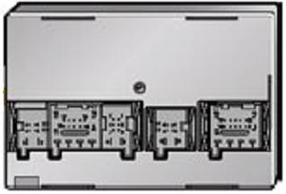
44 CHAPTER 10 Power Supply System 2011> Jettas equipped with the High version electrical system use the Vehicle Electrical System Control Module J519 to operate the power supply relays. These vehicles operate the same as the vehicles discussed in the previous exercises. 2011> Jettas equipped with the Low version electrical system use an electronic control module called the Converter Box J935 to operate the power supply relays, as shown in this simplified wiring diagram. (Note: This diagram does not show all of the circuits in either the 2011> Jetta Low Version Power Supply System 24
45 Chapter 10, Page > Jettas equipped with the High version electrical system use the Vehicle Electrical System Control Module J519 to operate the power supply relays. These vehicles operate the same as the vehicles discussed in the previous exercises. 2011> Jettas equipped with the Low version electrical system use an electronic control module called the Converter Box J935 to operate the power supply relays, as shown in this simplified wiring diagram. (Note: This diagram does not show all of the circuits in either the ignition switch or J935. The terminal 15, 50 and 75 signals are also sent to J519, but it is J935 which operates the power supply relays.) J935 is located in the relay panel above the fuse box. D: Ignition/Starter Switch J329: Terminal 15 Power Supply Relay J680: Terminal 75 Power Supply Relay 1 J681: Terminal 15 Power Supply Relay 2 J682: Terminal 50 Power Supply Relay For more information about the ignition switch and J935, refer to the wiring diagrams in ElsaWeb.
.")
46 2011> Jetta Low Version Power Supply System 2011> Jettas equipped with the Low version electrical system and KESSY (Keyless Entry and Start System) do not have a mechanical ignition switch (Ignition/Starter Switch D). In these vehicles, the Start System Button E738 sends a start request signal to the Electronic Steering Column Lock Control Module J764, which sends the terminal 15, 50 and 75 request signals to the Converter Box J935. J935 then operates the power supply relays the same as a vehicle that is not equipped with KESSY. E378: Start System Button J329: Terminal 15 Power Supply Relay J680: Terminal 75 Power Supply Relay 1 J681: Terminal 15 Power Supply Relay 2 25
47 Chapter 10, Page > Jettas equipped with the Low version electrical system and KESSY (Keyless Entry and Start System) do not have a mechanical ignition switch (Ignition/Starter Switch D). In these vehicles, the Start System Button E738 sends a start request signal to the Electronic Steering Column Lock Control Module J764, which sends the terminal 15, 50 and 75 request signals to the Converter Box J935. J935 then operates the power supply relays the same as a vehicle that is not equipped with KESSY. E378: Start System Button J329: Terminal 15 Power Supply Relay J680: Terminal 75 Power Supply Relay 1 J681: Terminal 15 Power Supply Relay 2 J682: Terminal 50 Power Supply Relay J764: Electronic Steering Column Lock Control Module Note: J682 is a five terminal relay on vehicles with KESSY. The 5th terminal provides diagnostic feedback signal from J682 to J764, which verifies that J682 is operating correctly in the event that J764 does not receive an RPM signal during starting. For more information on the 2011 Jetta electrical system, refer to SSP , The 2011 Jetta.
 are carried on a dedicated single function wire.")
48 Hardwired vs. Virtual Signals Electrical signals are carried between control modules in two ways, as hardwired signals or virtual signals. It is important to understand the difference between them. The terminal 50 signal shown above is an example of a hardwired signal. Hardwired signals (also called discrete signals) are carried on a dedicated single function wire. In this example, a hardwire carries the 50 signal between all of the components in the circuit. The advantage of a hardwired signal is that it can be easily verified. In this case the terminal 50 signal is a positive voltage that can be measured with a with a DVOM (and possibly also with MVB). The disadvantage is 26
49 Chapter 10, Page 26 The terminal 50 signal shown above is an example of a hardwired signal. Hardwired signals (also called discrete signals) are carried on a dedicated single function wire. In this example, a hardwire carries the 50 signal between all of the components in the circuit. The advantage of a hardwired signal is that it can be easily verified. In this case the terminal 50 signal is a positive voltage that can be measured with a with a DVOM (and possibly also with MVB). The disadvantage is that every hardwired signal requires a dedicated wire, increasing the complexity of the wiring harness. The terminal 75 (X) signal shown above is an example of a virtual signal. While it may be carried between some components as a hardwired signal, it is carried between others as a virtual signal. In this example: The terminal 75 signal originates in the ignition switch and is sent to J527 via a hardwire. J527 receives the 75 signal and converts it to a CAN message (virtual 75 signal) which is broadcast to J519 on the convenience CAN. J519 receives the CAN message and internally switches power to a hardwired 75 circuit. The 75 signal is received by the load reduction relay. The load reduction relay closes and sends power to various components. When the ignition switch is in the start position, the ignition switch interrupts the 75 signal to J527. J527 broadcasts a CAN message to J519 instructing it to switch off the 75 signal to the load reduction relay. When the key is returned to the RUN position, the process repeats. While the signal in the hardwired portions of the circuit can be verified with a DVOM, the virtual portion can only be verified with MVB. The advantage of virtual signals is that many different signals can be carried on the CAN wires, eliminating the individual hardwire circuits. This reduces the complexity of the warning harness. The examples shown above are used to explain the concept of virtual signals. The actual connection for virtual signals varies per vehicle, although the concept remains the same. For example, in some Volkswagens, terminals 15 and 50 are hardwired, while terminals 75, S and P are virtual signals
50 CHAPTER 11 Exercise 6 Exercise 6 Heated Seat Operation Objective: Trace the various signals that operate the heated seats. In this exercise you will examine the operation of the heated seats using signal tracing and the DSO. 27
51 Chapter 11, Page 27 No Notes
52 Exercise 6 Heated Seat Operation - REVIEW The Driver s Heated Seat Adjuster E94 sends a voltage signal that varies depending on the temperature setting. Higher temperature settings send higher voltage signals and vice versa. The voltage signal from E94 is sent to the Front Heated Seats Control Module J774, which uses the signal to regulate seat temperature by controlling the current sent to the heated seat elements. E94 is connected in parallel with the Driver s Heated Seat Temperature Sensor G59, 28
53 Chapter 11, Page 28 The Driver s Heated Seat Adjuster E94 sends a voltage signal that varies depending on the temperature setting. Higher temperature settings send higher voltage signals and vice versa. The voltage signal from E94 is sent to the Front Heated Seats Control Module J774, which uses the signal to regulate seat temperature by controlling the current sent to the heated seat elements. E94 is connected in parallel with the Driver s Heated Seat Temperature Sensor G59, which is a Negative Temperature Coefficient (NTC) thermistor (temperature sensor). As the heated seat element warms up, the resistance of G59 drops. The lower resistance of G59 in turn pulls down the voltage signal from E94. This drop in voltage is used by J774 to regulate the temperature of the seat. When a predetermined voltage threshold is reached, J774 cycles the current to the heated seat elements on and off to maintain the desired temperature. See the next page for more detail.
54 Exercise 6 Heated Seat Operation - REVIEW When the voltage signal at the Front Heated Seats Control Module J774 is reduced to a predetermined voltage threshold, J774 shuts off current to the heated seat elements. As the heated seat elements cool down, the resistance of G59 increases and so the voltage signal at J774 also increases. When a predetermined voltage threshold is reached, J774 turns current to the heated seat elements back on and the cycle repeats, maintaining the desired seat temperature. 29
55 Chapter 11, Page 29 No Notes
 with the DSO set to 50 ms/div.")
56 Exercise 6 Heated Seat Operation - REVIEW The illustration on the previous page shows the signal to the heated seat elements measured in amps using the inductive pick-up. If we were to measure the voltage of one of the ON periods (A) with the DSO set to 50 ms/div., we would see that the Front Heated Seats Control Module J774 uses a PWM (Pulse Width Modulated Signal) signal to regulate the current to the heated seat elements. The elements get the same amount of current (amperage) no matter what setting has been selected on the Heated Seat Adjuster E94. Seat temperature is controlled by the length of time that the 30
57 Chapter 11, Page 30 The illustration on the previous page shows the signal to the heated seat elements measured in amps using the inductive pick-up. If we were to measure the voltage of one of the ON periods (A) with the DSO set to 50 ms/div., we would see that the Front Heated Seats Control Module J774 uses a PWM (Pulse Width Modulated Signal) signal to regulate the current to the heated seat elements. The elements get the same amount of current (amperage) no matter what setting has been selected on the Heated Seat Adjuster E94. Seat temperature is controlled by the length of time that the elements remain ON.

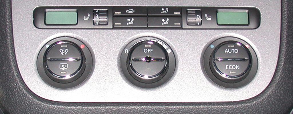
58 Exercise 6 Heated Seat Operation - REVIEW Heated Seat Activation Sequence: We will use the driver s seat as an example of the heated seat activation sequence. The passenger s seat and heated rear seats, if so equipped, are similar. The Climatic/Climatronic system does not have to be on to operate the heated seats, but the engine must be running. If the engine is running and the charging system voltage is sufficient to support heated seat operation, the Vehicle Electrical System Control Module J519 sends an 31
59 Chapter 11, Page 31 Heated Seat Activation Sequence: We will use the driver s seat as an example of the heated seat activation sequence. The passenger s seat and heated rear seats, if so equipped, are similar. The Climatic/Climatronic system does not have to be on to operate the heated seats, but the engine must be running. If the engine is running and the charging system voltage is sufficient to support heated seat operation, the Vehicle Electrical System Control Module J519 sends an enabling signal to the Front Heated Seats Control Module J774. If the charging system voltage drops below a predetermined level, the load management function of J519 does not send the signal, which prevents heated seat operation. The driver selects the desired seat temperature using the Driver s Heated Seat Adjuster E94. E94 sends a variable voltage signal to J774, which is connected in parallel with the Driver s Heated Seat Temperature Sensor G59. G59 is a Negative Temperature Coefficient (NTC) thermistor. J774 reads the voltage signal from E94 and uses this value to determine the desired seat temperature. J774 then sends current to the heated seat elements, which is the same amperage regardless of the E94 setting. Seat temperature is controlled by the length of time the heated seat elements remain on. As the heated seat elements warm up, the resistance of G59 decreases. Since G59 is connected in parallel with E94, a reduction in the resistance of G59 pulls the voltage signal from E94 down. This causes the voltage signal at J774 to decrease. When a predetermined voltage threshold is reached, J774 shuts off current to the heated seat elements. (The values of the threshold vary between vehicles and it is not necessary to know what they are to diagnose and repair the system.) As the heated seat elements cool down, the resistance of G59 increases and so the voltage signal at J774 also increases. When a predetermined voltage threshold is reached, J774 turns current to the heated seat elements back on and the cycle repeats, maintaining the desired seat temperature. For more information refer to the Front Heated Seats Control Module J774 Pin Assignment handout.

60 CHAPTER 12 Control Module Coding This flowchart provides a suggested procedure to help you diagnose suspected coding problems. Since it is impossible to predict every diagnostic situation that you might encounter, you must adapt the steps to your situation. Note that the first step after comparing the vehicle coding to the earliest coding is the same if you answer either Yes or No (Check Technical Bulletins and Tech Tips for coding updates). If the vehicle coding is the same as the earliest coding, the complaint could be resolved by performing the update (as long as the update relates to the complaint). If the coding is not the same, you must verify that it was changed because a Technical Bulletin or Tech Tip recommended changing it. If you change it back Tap to open, expand window with fingers and tap screen to view each line. 32
61 Chapter 12, Page 32 This flowchart provides a suggested procedure to help you diagnose suspected coding problems. Since it is impossible to predict every diagnostic situation that you might encounter, you must adapt the steps to your situation. Note that the first step after comparing the vehicle coding to the earliest coding is the same if you answer either Yes or No (Check Technical Bulletins and Tech Tips for coding updates). If the vehicle coding is the same as the earliest coding, the complaint could be resolved by performing the update (as long as the update relates to the complaint). If the coding is not the same, you must verify that it was changed because a Technical Bulletin or Tech Tip recommended changing it. If you change it back to the earliest coding, you might recreate a problem that had already been addressed. If a coding problem is suspected, always baseline the vehicle by creating a VSD Self-Diagnosis Log before making any coding changes. The Self-Diagnosis Log: Provides you with a paper copy that can be used to compare the current vehicle coding against the earliest coding found in the Paperless GFF Diagnosis Log. Provides you with documentation of the repair should you need to change the coding from the current vehicle coding. Provides you with a record of current vehicle coding should you change the coding and then decide to change it back. Remember to relate the customer complaint to the suspected coding problem. For example, a change in radio coding would probably have little influence on the operation of the engine management system. If you are replacing a control module and are unable to obtain the code from the original module and use the coding from Paperless GFF in the replacement module, check for coding updates before returning the vehicle to the customer. If the coding update was performed in the original module but not the replacement module, the customer will complain that a problem that had previously been repaired has returned.
62 CHAPTER 13 Exercise 7 Exercise 87 Keyless Control Module Remote Coding Adaptation Objective: Demonstrate the ability to program properly a keyless code a control remote. module using the various methods available. It is important that you fully understand all facets of key operation. This exercise examines the keyless remote in preparation for the next exercise, Review which covers the Immobilizer system. 33
63 Chapter 13, Page 33 No Notes


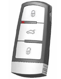
64 CHAPTER 14 Key Functions The key fobs have a frequency of either 433 MHz or 315 MHz. The LED on the key fob indicates that a signal is being sent. Passat and CC key fobs must be ordered by VIN and can only be matched to that specific vehicle. Tap to open, expand window with fingers and tap screen to view each line. 34
65 Chapter 14, Page 34 No Notes
66 CHAPTER 15 Exercise 8 Exercise 8 Keyless Remote Adaptation Objective: Demonstrate the ability to program a keyless remote. It is important that you fully understand all facets of key operation. This exercise examines the keyless remote in preparation for the next exercise, which covers the Immobilizer system. 35
67 Chapter 15, Page 35 No Notes
68 CHAPTER 16 Immobilizer Functions Immobilizer Basic Function All Immobilizer systems, regardless of the version or generation, have the same primary function, which is to prevent the engine from starting unless a valid key is inserted in the ignition switch. When the key is inserted into the ignition, a read coil located in the ignition switch energizes a chip in the key which generates a signal. The read coil sends this signal to the Immobilizer Control Module. The Immobilizer Control Module uses this signal to verify that this is the correct key for the vehicle and authorizes the engine start request. Note: Please refer to SSP Immobilizer Systems for more detailed information on Immobilizer operation! 36
69 Chapter 16, Page 36 No Notes
 New Beetle 2002-2005 Passat Adaptation Immobilizer IV Immobilizer IV A")
70 Which Version of Immobilizer Do I Have? IMMOBILIZER VERSION VEHICLES ADAPTATION TYPE Immobilizer II vehicles1 Adaptation Immobilizer III Jetta (A4) New Beetle Passat Adaptation Immobilizer IV Immobilizer IV A Immobilizer IV C Immobilizer IV D Phaeton 2004 to 2010 Touareg 2005 to UDS3 A5 Tiguan up to week 22/09 Eos Tiguan from week 22/09 A to 2010 B6 All CC Adaptation - Download starting with Adaptation - Download starting with 2008 Download Download Immobilizer V 2011 Touareg and Jetta Download 37
71 Chapter 16, Page 37 No Notes
72 Identifying Touareg Immobilizer Touaregs built near the change-over can have either Immobilizer IV with adaptation or download. Determine the Immobilizer version using the method below. Touaregs have a prefix in the serial number: - VWZ: This vehicle uses adaptation (off-line). - VWY: This vehicle uses download (on-line adaptation) and has had a new J518 installed that has not yet been adapted. - VWX: After a VWY component has been adapted, the serial number changes to VWX. Identifying Touareg Immobilizer GF may offer several choices of Immobilizer versions. Take care when selecting them because versions sometimes change mid-model year. This is especially true of the splits between Immobilizer II and III and Immobilizer IV with adaptation and Immobilizer IV with download. Do not assume that a particular year has the Immobilizer version that was listed in the Immobilizer version chart shown previously. GFF is the preferred method of determining the correct Immobilizer version. If you repeatedly select the incorrect Immobilizer version, the test plan may lock up the Immobilizer system. Some vehicles have different choices for Immobilizer versions in GF. Since you must select the Immobilizer version manually in GF, you may select the wrong version. GFF is the preferred method for selecting Immobilizer versions because it automatically selects the correct one. 38
73 Chapter 16, Page 38 No Notes
74 Immobilizer Component Replacement Job Aid The Immobilizer handout shows which components must be replaced in case of a failure in another Immobilizer component. This information should not be used instead of GFF test plans! It is only for your reference. 39
75 Chapter 16, Page 39 No Notes

76 Immobilizer Tips and Tricks Tap to open, expand window with fingers and tap screen to view each line. 40
77 Chapter 16, Page 40 No Notes
78 CHAPTER 17 Exercise 9 Exercise 9 Immobilizer Objective: Understand and explain the operation of the Immobilizer system on your vehicle. The Immobilizer system is often misunderstood, making it a prime area of concern for technicians. This exercise shows how to identify different Immobilizer systems and work on them without fear. 41
79 Chapter 17, Page 41 No Notes
.")
80 CHAPTER 18 Bluetooth Bluetooth Overview Bluetooth allows devices, such as cell phones, to transmit data a short distance to an onboard device to allow for hands-free talking and data transfer The chips are very small, allowing it to be placed inside of mobile devices Bluetooth Specifications The data transmission rate is up to 1Mbit/s (megabit per second). It takes 8Mbits to make up 1MB (megabyte) The range of transmitters is normally about 10 meters (33 feet) A PIN is used to pair devices to the Bluetooth system Each device has a unique ID worldwide 42
81 Chapter 18, Page 42 Bluetooth Specifications The data transmission rate is up to 1Mbit/s (megabit per second). It takes 8Mbits to make up 1MB (megabyte) The range of transmitters is normally about 10 meters (33 feet) A PIN is used to pair devices to the Bluetooth system Each device has a unique ID worldwide Interference from other similar-frequency devices is reduced by: - Short and flexible data packages - Automatic repeating of faulty data packages - Changing the frequency of transmitting and receiving frequencies 1600 times per second


82 SYSTEM NAME AND (PR) CODE UHV (9W0) UHV Low (9W2) UHV High (9W3) UHV High (9W7) Volk-L VW Accessory Option U-Connect Factory and Accessory Option VEHICLES Bluetooth not installed 2009 and 2010 vehicles except for NB, NBC, Routan 2009 and 2010 vehicles except for NB, NBC, Routan 2011 vehicles except Eos, NB, NBC, Routan 2005 to 2010 vehicles except for NB, NBC, Routan Routan Only 43
83 Chapter 18, Page 43 Not every Bluetooth device works with every Volkswagen Bluetooth system.
84 Bluetooth Identification It is not easy to identify the level of Bluetooth on your vehicle by simply looking at components. Refer to Technical Bulletin Bluetooth System Identification. This bulletin will lead you through the identification process. Some vehicles appear to have Bluetooth on Bluetooth Capabilities Refer to the appropriate Technical Bulletin (examples listed below, subject to change): Bluetooth UHV High Overview Bluetooth UHV Low Overview Bluetooth Issues Refer to the Technical Bulletin , Bluetooth UHV Low (9W2), Various Complaints Describes issues such as: - Inability to pair a phone - Sporadic inability to pair a phone 44
85 Chapter 18, Page 44 Bluetooth Identification It is not easy to identify the level of Bluetooth on your vehicle by simply looking at components. Refer to Technical Bulletin Bluetooth System Identification. This bulletin will lead you through the identification process. Some vehicles appear to have Bluetooth on them when they actually do not (example: all CC s and RNS 510 vehicles have the phone icon on the steering wheel whether they are equipped or not). It is the coding of the UHV-High module that determines whether the steering wheel button is a mute button or a phone button. Bluetooth Issues Refer to the Technical Bulletin , Bluetooth UHV Low (9W2), Various Complaints Describes issues such as: - Inability to pair a phone - Sporadic inability to pair a phone - Sporadically dropped calls - Audio streaming inoperative - Audio streaming quality including speaker crackling Technical Bulletins are subject to change at any time! Always refer to ElsaWeb for the latest version!
86 CHAPTER 19 Exercise 10 Exercise 10 Bluetooth Objective: Identify and operate the Bluetooth system on your vehicle. Bluetooth is one of the most misunderstood systems on the vehicle, by both the dealer and the customer. This is due to many subtle variations even within the same model year, and technicians do not often get to see all of the different versions. This exercise helps find appropriate Technical Bulletins and work with a Bluetooth system on a vehicle. 45

87 CHAPTER 20 Course Review Review Please take a moment to verify your address and then press OK. This action will allow a PDF to be compiled and sent directly to your . You may repeat this process for an additional address you want the results sent to. Post Assessment Goodbye 46
Tire Pressure Monitoring Systems
 Service Training Self-Study Program 861603 Tire Pressure Monitoring Systems Volkswagen of America, Inc. Volkswagen Academy Printed in U.S.A. Printed 10/2006 Course Number 861603 2006 Volkswagen of America,
SCHEMATIC AND ROUTING DIAGRAMS
 2004 ACCESSORIES & EQUIPMENT Keyless Entry - Corvette SCHEMATIC AND ROUTING DIAGRAMS KEYLESS ENTRY SCHEMATICS Fig. 1: Driver Door Schematic Courtesy of GENERAL MOTORS CORP. Fig. 2: Passenger Door Schematic
2001 Chevrolet Corvette ACCESSORIES & EQUIPMENT Remote Keyless Entry Systems - Corvette
 DESCRIPTION 2001 ACCESSORIES & EQUIPMENT Remote Keyless Entry Systems - Corvette Remote Keyless Entry (RKE) system is controlled by Remote Function Actuation (RFA) system. Transmitter allows remote control
Technical Bulletin AA 304. Central Locking System. m.y. 97
 Technical Bulletin Subject: Model(s): Central Locking System Cabriolet m.y. 97 Group: Number: Date: 01 96 11 Nov. 29, 1996 The following Repair Manual pages are new and will be integrated with the next
KEYLESS ENTRY SYSTEM & TIRE PRESSURE MONITOR ACCESSORIES & EQUIPMENT General Motors Corp. - Remote Keyless Entry System
 KEYLESS ENTRY SYSTEM & TIRE PRESSURE MONITOR 1998 ACCESSORIES & EQUIPMENT General Motors Corp. - Remote Keyless Entry System DESCRIPTION Remote Keyless Entry (RKE) system is controlled by Remote Function
Phaeton Convenience and Safety Electronics
 Service. Self-Study Programme 273 Phaeton Convenience and Safety Electronics Design and Function Open sesame - thanks to a new system for entry and start authorisation, the Phaeton can be accessed without
Service Bulletin Immobilizer System (Type 6) (Supersedes , dated February 20, 2009; see REVISION SUMMARY) February 22, 2013
 (Supersedes , dated February 20, 2009; see REVISION SUMMARY) February 22, 2013") Service Bulletin 06-033 Applies To: 2007-09 MDX ALL 2007-12 RDX ALL February 22, 2013 Immobilizer System (Type 6) (Supersedes 06-033, dated February 20, 2009; see REVISION SUMMARY) REVISION SUMMARY This
Service Bulletin 06-033 Applies To: 2007-09 MDX ALL 2007-12 RDX ALL February 22, 2013 Immobilizer System (Type 6) (Supersedes 06-033, dated February 20, 2009; see REVISION SUMMARY) REVISION SUMMARY This
VEHICLE THEFT/SECURITY SYSTEMS
 WJ VEHICLE THEFT/SECURITY SYSTEMS 8Q - 1 VEHICLE THEFT/SECURITY SYSTEMS CONTENTS... 6 VEHICLE THEFT SECURITY SYSTEM... 1 VEHICLE THEFT SECURITY SYSTEM INDEX AND DOOR AJAR SWITCH... 3 DRIVER CYLINDER LOCK
2002 Dodge Intrepid ES ACCESSORIES & EQUIPMENT Anti-Theft Systems - Concorde, Intrepid & 300M
 DESCRIPTION SENTRY KEY IMMOBILIZER SYSTEM 2002-03 ACCESSORIES & EQUIPMENT Anti-Theft Systems - Concorde, Intrepid & 300M CAUTION: Large metallic objects, or items such as magnetic pass-keys, may cause
Keyless Go (KG) 218 HO Keyless Go (GC_JL_JM)
 218 HO Keyless Go (GC_JL_JM)") Keyless Go (KG) 218 HO Keyless Go (GC_JL_JM) 04-05-02 1 These technical training materials are current as of the date noted on the materials, and may be revised or updated without notice. Always check
Keyless Go (KG) 218 HO Keyless Go (GC_JL_JM) 04-05-02 1 These technical training materials are current as of the date noted on the materials, and may be revised or updated without notice. Always check
2001 Dodge Durango ACCESSORIES & EQUIPMENT' 'Anti-Theft Systems - Dakota & Durango 2001 ACCESSORIES & EQUIPMENT
 DESCRIPTION VEHICLE THEFT SECURITY SYSTEM 2001 ACCESSORIES & EQUIPMENT Anti-Theft Systems - Dakota & Durango Vehicle Theft Security System (VTSS) provides perimeter protection against unauthorized use
Convenience CAN databus
 Convenience CAN databus The convenience CAN databus operates with a transmission rate of 100 kbit/s. Onboard power supply control unit J519 with databus diagnostic interface J533 (gateway) CLIMAtronic
Service Circular 2005 Maintenance Service Circular
 Subject: 2005 Model Year Volkswagen new Jetta Maintenance 2005 Maintenance Number: VMS-05-13 MAINTENANCE SERVICE CIRCULAR, VMS-05-13 DATED September 26, 2005, SUPERSEDES MAINTENANCE SERVICE CIRCULAR VMS-05-02
Holden VZ 3.6L ECU & Powertrain Interface Module Linking Instructions
 Holden VZ 3.6L 2004-2006 ECU & Powertrain Interface Module Linking Instructions Contents Page In Brief PIM Replacement, ECM Replacement 2 VZ 3.6L System Overview 3 PIM Functions 4 PIM Location 4 ECM Functions
DESCRIPTION & OPERATION
 DESCRIPTION & OPERATION 1998-99 SUSPENSION Electronic - Real Time Damping - Corvette The Real Time Damping (RTD) system automatically controls vehicle ride by independently controlling a damper solenoid
 Page 1 of 6 2006 Dodge Dakota 4.7L Eng VIN J 1Search Print Date: FRONT CONTROL MODULE (FCM) MODULE-FRONT CONTROL DESCRIPTION Fig 1: IPM Wiring Connectors Courtesy of DAIMLERCHRYSLER CORP. The Front Control
POWER LOCK SYSTEMS 8P - 1 POWER LOCK SYSTEMS TABLE OF CONTENTS
 AN POWER LOCK SYSTEMS 8P - 1 POWER LOCK SYSTEMS TABLE OF CONTENTS page GENERAL INFORMATION INTRODUCTION...1 POWER LOCK SYSTEM...1 REMOTE KEYLESS ENTRY SYSTEM...1 DESCRIPTION AND OPERATION CENTRAL TIMER
Exterior overview. 2 Addendum TR1478. Addendum
 Contents This addendum describes features that are specific to the Roadster 2.5. It also provides updates and/or corrections that improve the accuracy or quality of the information published in your owner
Platform Battery Drain Diagnosis Procedure - keywords accessory aftermarket generator low operation regulator volt voltage #PIC3589A - (06/14/2006)
") Document ID# 1838899 2004 Cadillac CTS Subject: Platform Battery Drain Diagnosis Procedure - keywords accessory aftermarket generator low operation regulator volt voltage #PIC3589A - (06/14/2006) Models:
Document ID# 1838899 2004 Cadillac CTS Subject: Platform Battery Drain Diagnosis Procedure - keywords accessory aftermarket generator low operation regulator volt voltage #PIC3589A - (06/14/2006) Models:
Onboard power supply management
 Onboard power supply management The onboard power supply J519 Functions of onboard power supply control unit Until now s and relays functioned at different locations in the vehicle. In the onboard power
DESCRIPTION & OPERATION
 ANTI-THEFT SYSTEM 1998 ACCESSORIES & EQUIPMENT General Motors Corp. - Anti-Theft System DESCRIPTION & OPERATION WARNING: Deactivate air bag system before performing any service operation. See AIR BAG RESTRAINT
Phase 1 Workshop Home Study Guide
 Phase 1 Workshop Home Study Guide Vehicle Electrical-Electronics Troubleshooting Training Written and Developed by Vince Fischelli Director of Training Veejer Enterprises Inc. / Garland, Texas U.S.A. Phone:
Service Training. Audi A5 - Networking. Self-Study Programme 395
 Service Training Audi A5 - Networking Self-Study Programme 395 Innovations in the electrical system and electronics on the Audi A5 The number of s in motor vehicles continues to increase, and the Audi
SCHEMATIC AND ROUTING DIAGRAMS
 2004 ACCESSORIES & EQUIPMENT Theft Deterrent - Corvette SCHEMATIC AND ROUTING DIAGRAMS THEFT DETERRENT SYSTEM SCHEMATICS Fig. 1: Theft Deterrent Relay, Security Indicator, Lighting and Horn References
SECTION 12M - SUPPLEMENTAL RESTRAINT SYSTEM (VERSIONS 8.0 AND 8.1)
") SECTION 12M - SUPPLEMENTAL RESTRAINT SYSTEM (VERSIONS 8.0 AND 8.1) IMPORTANT Before performing any Service Operation or other procedure described in this Section, refer to Section 00 CAUTIONS AND NOTES
SECTION 12M - SUPPLEMENTAL RESTRAINT SYSTEM (VERSIONS 8.0 AND 8.1) IMPORTANT Before performing any Service Operation or other procedure described in this Section, refer to Section 00 CAUTIONS AND NOTES
DIAGNOSIS AND TESTING
 501-14-1 Handles, Locks, Latches and Entry Systems 501-14-1 DIAGNOSIS AND TESTING Locks, Latches and Entry Systems Refer to Wiring Diagrams Cell 117 for schematic and connector information. Special Tool(s)
High technology theft-prevention systems
 Lemme In! Mazda 626 & MPV Immobilizer System High technology theft-prevention systems have hit the automotive market full-force. Several manufacturers now offer antitheft protection integrated with the
Service Circular 2006 Maintenance Service Circular
 Subject: 2006 Model Year Volkswagen new Passat Maintenance Service Circular 2006 Maintenance Service Circular Number : VMS-05-14 MAINTENANCE SERVICE CIRCULAR, VMS-05-14 DATED November 30, 2005, SUPERCEDES
Update Programming Transmission Control Module (TCM) for Improved Upshifting. Condition. Production
 for Improved Upshifting. Condition. Production") Subject: Model(s): Update Programming Transmission ontrol Module (TM) for Improved Upshifting (OE) Touareg 3.2L V6 (eng. code BMX) 2005 2006 Group: Number: Date: 01 05 16 Dec. 20, 2005 Update Programming
Subject: Model(s): Update Programming Transmission ontrol Module (TM) for Improved Upshifting (OE) Touareg 3.2L V6 (eng. code BMX) 2005 2006 Group: Number: Date: 01 05 16 Dec. 20, 2005 Update Programming
INSTALLATION GUIDE Table of Contents
 CT-3100 Automatic transmission remote engine starter systems. What s included..2 INSTALLATION GUIDE Table of Contents Door lock toggle mode..... 4 Notice...2 Installation points to remember. 2 Features..2
Technical Service Bulletin
 17 Oil pressure light on and/or rattle noise from engine at cold start 17 08 23 2015411/6 November 21, 2008. Supersedes Technical Service Bulletin Group 17 number 08-05 dated July 22, 2008 for reasons
Scan Tool Does Not Communicate with Class 2 Device (W/O Immobilizer)
") Page 1 of 5 2002 GMC Truck Envoy - 4WD Bravada, Envoy, TrailBlazer (VIN S/T) Service Manual Body and Accessories Data Link Communications Diagnostic Information and Procedures Document ID: 754548 Scan
Page 1 of 5 2002 GMC Truck Envoy - 4WD Bravada, Envoy, TrailBlazer (VIN S/T) Service Manual Body and Accessories Data Link Communications Diagnostic Information and Procedures Document ID: 754548 Scan
Model(s) Year Eng. Code Trans. Code VIN Range From VIN Range To. All All All
 Year Eng. Code Trans. Code VIN Range From VIN Range To. All All All") Model(s) Year Eng. Code Trans. Code VIN Range From VIN Range To Touareg 2004 3.2L (BAA) All All All Condition 01 08 11 March 6, 2008 2015134 Supersedes Technical Bulletin Group 01 number 07-52 dated June
Model(s) Year Eng. Code Trans. Code VIN Range From VIN Range To Touareg 2004 3.2L (BAA) All All All Condition 01 08 11 March 6, 2008 2015134 Supersedes Technical Bulletin Group 01 number 07-52 dated June
INTRODUCTION PRELIMINARY DIAGNOSIS
 NO: 21-11-98 SUBJECT: Transmission Simulator Diagnostic Tool DATE: Dec. 11, 1998 NOTE: THIS INFORMATION APPLIES TO VEHICLES EQUIPPED WITH A 45RFE TRANSMISSION. DISCUSSION: A new transmission simulator
Service Bulletin Immobilizer System (Type 3) (Supersedes , dated June 27, 2007; see REVISION SUMMARY) February 22, 2013
 (Supersedes , dated June 27, 2007; see REVISION SUMMARY) February 22, 2013") Service Bulletin 01-053 See VEHICLES AFFECTED February 22, 2013 Immobilizer System (Type 3) (Supersedes 01-053, dated June 27, 2007; see REVISION SUMMARY) REVISION SUMMARY This service bulletin has been
Service Bulletin 01-053 See VEHICLES AFFECTED February 22, 2013 Immobilizer System (Type 3) (Supersedes 01-053, dated June 27, 2007; see REVISION SUMMARY) REVISION SUMMARY This service bulletin has been
The Transporter 2004 Electrical system
 Service. Self-study programme 311 The Transporter 2004 Electrical system Design and function The Transporter 2004 has an extensive network of electronic control units. Functions which were controlled in
KEYLESS ENTRY SYSTEM
 KEYLESS ENTRY SYSTEM 1995 Volvo 850 1995 ACCESSORIES & EQUIPMENT Volvo Keyless Entry Systems 850 DESCRIPTION & OPERATION 850 models with central locking and factory installed alarm system can be equipped
Document ID# Chevrolet Chevy Suburban - 4WD
 Page 1 of 8 Document ID# 757392 2003 Chevrolet Chevy Suburban - 4WD Print DTC C0455 Circuit Description The steering wheel position sensor (SWPS) provides one analog signal and 3 digital
Subject: GM Technical Assistance Information Form # D - (12/14/2006)
") Document ID# 1878635 2004 Cadillac CTS Subject: GM Technical Assistance Information Form #01-00-89-011D - (12/14/2006) Models: Attention: 2007 and Prior Passenger Cars and Trucks (Including Saturn) 2007
Document ID# 1878635 2004 Cadillac CTS Subject: GM Technical Assistance Information Form #01-00-89-011D - (12/14/2006) Models: Attention: 2007 and Prior Passenger Cars and Trucks (Including Saturn) 2007
DOC - WIRING 1985 GOLF GTI DOCUMENT
 05 May, 2018 DOC - WIRING 1985 GOLF GTI DOCUMENT Document Filetype: PDF 335.67 KB 0 DOC - WIRING 1985 GOLF GTI DOCUMENT The GTI model existed from 1985-1987, and again from 1990-1992, and the GTI 16v existed
SECTION Instrument Cluster and Panel Illumination
 413-00-i Instrument Cluster and Panel Illumination 413-00-i SECTION 413-00 Instrument Cluster and Panel Illumination CONTENTS PAGE DIAGNOSIS AND TESTING Instrument Cluster and Panel Illumination... 413-00-2
/15 September 23, Supersedes Technical Service Bulletin Group 46 number dated July 26, 2016 for reasons listed below.
 46 Brake noise analysis and handling 46 16 50 2034181/15 September 23, 2016. Supersedes Technical Service Bulletin Group 46 number 16-48 dated July 26, 2016 for reasons listed below. Model(s) Year VIN
2007 Chevrolet Corvette STEERING Steering Wheel and Column - Corvette. Steering Wheel and Column - Corvette
 2007 STEERING Steering Wheel and Column - Corvette SPECIFICATIONS FASTENER TIGHTENING SPECIFICATIONS Fastener Tightening Specifications Specification Application Metric English Actuator Retaining Screws
Charging System. Activity 11. Battery Drain Testing
 Charging System 812FJ Student Manual Charging System Activity 11 Battery Drain Testing Performance Objectives: Test for and measure battery drain using manufacturer s service procedures. Diagnose the cause
/6 March 31, Supersedes Technical Service Bulletin Group 27 number dated October 31, 2016 for reasons listed below.
 27 Vibrations felt at 1000 rpm and 3000 rpm 27 17 29 2036392/6 March 31, 2017. Supersedes Technical Service Bulletin Group 27 number 16-27 dated October 31, 2016 for reasons listed below. Model(s) Year
Quick Reference: Immobilizer III Service Procedures
 Notes: Before starting: Read these instructions completely. When working on an Immobilizer system, try to have all the vehicle keys available. Some repairs require the Adaptation of the keys. If you adapt
Auto Service Technician
 Auto Service Technician Organization Washburn Institute of Technology Program Number 47.0604 Instructional Level Certificate Target Population Grades 11 & 12 Post-secondary Description The Auto Service
SECTION Multifunction Electronic Modules
 419-10-i Multifunction Electronic Modules 419-10-i SECTION 419-10 Multifunction Electronic Modules CONTENTS PAGE DIAGNOSIS AND TESTING Smart Junction Box (SJB)... 419-10-2 Principles of Operation... 419-10-2
Model(s) Year Eng. Code Trans. Code VIN Range From VIN Range To
 Year Eng. Code Trans. Code VIN Range From VIN Range To") Model(s) Year Eng. Code Trans. Code VIN Range From VIN Range To All 1998-2010 All All All All Condition 27 10 01 May 26, 2010 2011894 Supersedes T. B. Group 27 number 08-06 dated Sept. 30, 2008 due to
Model(s) Year Eng. Code Trans. Code VIN Range From VIN Range To All 1998-2010 All All All All Condition 27 10 01 May 26, 2010 2011894 Supersedes T. B. Group 27 number 08-06 dated Sept. 30, 2008 due to
SCHEMATIC AND ROUTING DIAGRAMS
 2004 ACCESSORIES & EQUIPMENT Tire Pressure Monitoring - Corvette SCHEMATIC AND ROUTING DIAGRAMS TIRE PRESSURE MONITORING SYSTEM SCHEMATICS Fig. 1: Tire Pressure Monitoring System Schematics Courtesy of
ECT Display Driver Installation for AP2 Module
 ECT Display Driver Installation for AP2 Module Overview The ECT Display Driver is a small module with a removable wire harness that mounts behind the driver's foot well cover. All wiring connections are
Technical Service Bulletin Jul 9, Broad code
 Technical Service Bulletin Topic Market area Brand Transaction No. Level Status Steering wheel shimmy vibration and/or oscillation (8T) United States 444 Volkswagen of America, Inc. (6444),Canada 999 Volkswagen
2002 ENGINE PERFORMANCE. Self-Diagnostics - RAV4. Before performing testing procedures, check for any related Technical Service Bulletins (TSBs).
.") 2002 ENGINE PERFORMANCE Self-Diagnostics - RAV4 INTRODUCTION NOTE: Before performing testing procedures, check for any related Technical Service Bulletins (TSBs). To properly diagnosis and repair this
2002 ENGINE PERFORMANCE Self-Diagnostics - RAV4 INTRODUCTION NOTE: Before performing testing procedures, check for any related Technical Service Bulletins (TSBs). To properly diagnosis and repair this
Service Bulletin Immobilizer System (Type 7) February 22, (Supersedes , dated March 6, 2009; see REVISION SUMMARY)
 February 22, (Supersedes , dated March 6, 2009; see REVISION SUMMARY)") Service Bulletin 09-016 Applies To: See VEHICLES AFFECTED February 22, 2013 Immobilizer System (Type 7) (Supersedes 09-016, dated March 6, 2009; see REVISION SUMMARY) REVISION SUMMARY This service bulletin
Service Bulletin 09-016 Applies To: See VEHICLES AFFECTED February 22, 2013 Immobilizer System (Type 7) (Supersedes 09-016, dated March 6, 2009; see REVISION SUMMARY) REVISION SUMMARY This service bulletin
DTC U : Lost Communication With Anti-Lock Brake System (ABS) Control Module
 Control Module") Page 1 of 6 DTC U0100-U0299 Diagnostic Instructions 2008 Pontiac G8 G8 Service Manual Document ID: 1874258 Perform the Diagnostic System Check - Vehicle prior to using this diagnostic procedure. Review
Page 1 of 6 DTC U0100-U0299 Diagnostic Instructions 2008 Pontiac G8 G8 Service Manual Document ID: 1874258 Perform the Diagnostic System Check - Vehicle prior to using this diagnostic procedure. Review
Central locking. Central locking, components
 57-29 Central locking Central locking, components 1 - Door lock actuator, right front Removing and installing Page 57-30 2 - Door lock actuator, sliding door Removing and installing Page 57-30 3 - door
Model PRO 9649 Owner s Manual
 Model PRO 9649 Owner s Manual 3 Button Remote Security System with Starter Disable, & Keyless Entry IMPORTANT! In order to provide the highest possible level of security to your vehicle, this system is
Power Sliding Door (PSD) Diagnostic Approach. Fixing Intermittent Malfunctions. Power Sliding Door (PSD) Diagnostic Information
 Diagnostic Approach. Fixing Intermittent Malfunctions. Power Sliding Door (PSD) Diagnostic Information") Power Sliding Door (PSD) Diagnostic Information Power Sliding Door (PSD) The power sliding door (PSD) provides built-in diagnostics. This assists the service technicians during troubleshooting. The PSD
Power Sliding Door (PSD) Diagnostic Information Power Sliding Door (PSD) The power sliding door (PSD) provides built-in diagnostics. This assists the service technicians during troubleshooting. The PSD
Battery, Mounting and Cables - Battery and Cables Description and Operation
 Battery, Mounting and Cables - Battery and Cables Description and Operation COMPONENT LOCATION - SINGLE BATTERY VEHICLES Item 1 2 3 4 5 6 7 8 9 10 Description Jump start terminal negative (-) Jump start
Volkswagen Jetta Golf Gti A4 Service Manual
 Volkswagen Jetta Golf Gti A4 Service Manual 1999 2000 2001 We have made it easy for you to find a PDF Ebooks without any digging. And by having access to our ebooks online or by storing it on your computer,
 Page 1 of 86 BODY CONTROL MODULE 2012 Ford Focus 2.0L Eng SEL REQUESTED INFORMATION Body Control Module (BCM) [ Removal And Installation ] Removal NOTE: Removal steps in this procedure may contain installation
VOLUNTARY SAFETY RECALL CAMPAIGN QUEST FUEL PUMP CONTROL MODULE
 Reference: NTB12-022a April 12, 2012 Date: VOLUNTARY SAFETY RECALL CAMPAIGN 2011-2012 QUEST FUEL PUMP CONTROL MODULE This bulletin has been amended. The NHTSA # and OWNER S LETTER have been added. Please
QUICK START GUIDE FOR ACCESS CONTROL BOARDS. DX Series Four Door TCP/IP Web Server Controller. Model: ACP-DXEL4
 QUICK START GUIDE FOR ACCESS CONTROL BOARDS DX Series Four Door TCP/IP Web Server Controller Model: ACP-DXEL Table of Contents 0- Introduction 0 - Overview 0. - Package Contents 0. - Installation Requirements
1. Ignition Key IGNITION KEY A: GENERAL SL-2
 SECURITY AND LOCKS SECURITY AND LOCKS IGNITION KEY 1. Ignition Key A: GENERAL A keyless entry system with a keyfob type transmitter is introduced. On models with immobilizer system, a transponder is assembled
L I M I T E D L I F E T I M E W A R R A N T Y
 L I M I T E D L I F E T I M E W A R R A N T Y Products manufactured and sold by OMEGA RESEARCH & DEVELOPMENT, INC. (the Company), are warranted to be free from defects in materials and workmanship under
Service Bulletin Immobilizer System (Type 1) (Supersedes , dated August 27, 2002) May 6, 2003
 (Supersedes , dated August 27, 2002) May 6, 2003") Service Bulletin 00-039 Applies To: 1997 01 Prelude ALL May 6, 2003 Immobilizer System (Type 1) (Supersedes 00-039, dated August 27, 2002) All 1997 01 Preludes have a Type 1 immobilizer system that disables
Service Bulletin 00-039 Applies To: 1997 01 Prelude ALL May 6, 2003 Immobilizer System (Type 1) (Supersedes 00-039, dated August 27, 2002) All 1997 01 Preludes have a Type 1 immobilizer system that disables
SECTION Interior Lighting
 417-02-i Interior Lighting 417-02-i SECTION 417-02 Interior Lighting CONTENTS PAGE DIAGNOSIS AND TESTING Interior Lighting... 417-02-2 Principles of Operation... 417-02-2 Inspection and Verification...
" MANUALLY OVERRIDING YOUR SYSTEM
 Model PRO 2000aS Owner s Manual 3 Button Remote Security System with Keyless Entry IMPORTANT! In order to provide the highest possible level of security to your vehicle, this system is equipped with selectable
EQUIPMENT - MAIN BODY 7-1 SECTION 7 EQUIPMENT CONTENTS
 EQUIPMENT - MAIN BODY 7-1 SECTION 7 EQUIPMENT CONTENTS Engine Immobiliser System...7-1 Exterior Lights...7-2 Combination Meter...7-2 Smart Wiring System (SWS)...7-3 General Information...7-3 Functions
POWER MIRROR SYSTEMS
 ZJ POWER MIRROR SYSTEMS 8T - 1 POWER MIRROR SYSTEMS CONTENTS AUTOMATIC DAY/NIGHT MIRROR... 6 OUTSIDE POWER MIRRORS... 1 OUTSIDE POWER MIRRORS INDEX GENERAL INFORMATION INTRODUCTION... 1 MEMORY SYSTEM...
VEHICLE THEFT/SECURITY SYSTEMS
 ZG VEHICLE THEFT/SECURITY SYSTEMS 8Q - 1 VEHICLE THEFT/SECURITY SYSTEMS CONTENTS page GENERAL INFORMATION ARMING... 1 DISARMING... 2 INTRODUCTION... 1 POWER-UP MODE... 2 TAMPER ALERT... 2 DESCRIPTION AND
Diesel Technology: Electrical and Electronic Systems
 Diesel Technology: Electrical and Electronic Systems Instructional/Task Analysis 2. Composition of atoms Unit 1: Introduction to Diesel Electrical and Electronic Systems 3. Electrical charges in atoms
2010 Flex Workshop Manual. REMOVAL AND INSTALLATION Procedure revision date: 12/10/2010
 SECTION 501-12: Instrument Panel and Console REMOVAL AND INSTALLATION Procedure revision date: 12/10/2010 Refrigerator Rear console Item Part Number Description 1 04567 Front finish panel 2 045A90B Bottom
The Touareg Electrical System
 Service. Self-Study Programme 298 The Touareg Electrical System Design and Function Vehicles with off-road capability are no longer just utility vehicles for a limited group of people. At all levels in
SECTION Handles, Locks, Latches and Entry Systems
 501-14-i Handles, Locks, Latches and Entry Systems 501-14-i SECTION 501-14 Handles, Locks, Latches and Entry Systems CONTENTS PAGE DIAGNOSIS AND TESTING Handles, Locks, Latches and Entry Systems... 501-14-2
Model CSI-300 Owner s Manual
 Model CSI-300 Owner s Manual 4 Button Remote Security System with Dual Stage Shock Sensor IMPORTANT! In order to provide the highest possible level of security to your vehicle, this system is equipped
FORD MONDEO Quick Reference Guide
 FORD MONDEO Quick Reference Guide About This Quick Reference Guide We have created this guide to help you get to know certain features of your vehicle. It only contains basic instructions to get you started
SECURITY CONTROL SYSTEM
 BODY EXTERIOR, DOORS, ROOF & VEHICLE SECURITY SECTION SEC A SECURITY CONTROL SYSTEM B C D CONTENTS E BASIC INSPECTION... 3 DIAGNOSIS AND REPAIR WORKFLOW... 3 Work Flow...3 INSPECTION AND ADJUSTMENT...
MODULE 6 Lower Anchors & Tethers for CHildren
 National Child Passenger Safety Certification Training Program MODULE 6 Lower Anchors & Tethers for CHildren Topic Module Agenda: 50 Minutes Suggested Timing 1. Introduction 2 2. Lower Anchors and Tether
Model AX-510 Owner s Manual
 Model AX-510 Owner s Manual 4 Button Remote Security System with Dual Stage Shock Sensor IMPORTANT! In order to provide the highest possible level of security to your vehicle, this system is equipped with
# : SMU - Revised DTC P0341 Camshaft Position (CMP) Sensor Performance - (Feb 20, 2002)
 Sensor Performance - (Feb 20, 2002)") Page 1 of 7 2002 Buick Regal Century, Regal (VIN W) Service Manual Engine Document ID: 861441 #02-06-04-008: SMU - Revised DTC P0341 Camshaft Position (CMP) Sensor Performance - (Feb 20, 2002) Subject:
Page 1 of 7 2002 Buick Regal Century, Regal (VIN W) Service Manual Engine Document ID: 861441 #02-06-04-008: SMU - Revised DTC P0341 Camshaft Position (CMP) Sensor Performance - (Feb 20, 2002) Subject:
KEYLESS OPERATION SYSTEM (KOS)
") 42B-1 GROUP 42B KEYLESS OPERATION SYSTEM (KOS) CONTENTS GENERAL INFORMATION 42B-2 SPECIAL TOOLS 42B-8 42B-9 STANDARD FLOW OF DIAGNOSTIC TROUBLESHOOTING 42B-9 DIAGNOSTIC FUNCTION 42B-9 ID CODES REGISTRATION
42B-1 GROUP 42B KEYLESS OPERATION SYSTEM (KOS) CONTENTS GENERAL INFORMATION 42B-2 SPECIAL TOOLS 42B-8 42B-9 STANDARD FLOW OF DIAGNOSTIC TROUBLESHOOTING 42B-9 DIAGNOSTIC FUNCTION 42B-9 ID CODES REGISTRATION
Convenience system central control unit
 Convenience system central control unit The convenience system central control unit monitors and controls the following functions: Convenience system central control unit central locking unlocking the
54-1 GROUP 54 CHASSIS ELECTRICAL CONTENTS CHASSIS ELECTRICAL... 54A SIMPLIFIED WIRING SYSTEM (SWS)... 54B
... 54B") 54-1 GROUP 54 CHASSIS ELECTRICAL CONTENTS............................... 54A SIMPLIFIED WIRING SYSTEM (SWS).................... 54B 54A-2 GROUP 54A CHASSIS ELECTRICAL CONTENTS BATTERY..................
54-1 GROUP 54 CHASSIS ELECTRICAL CONTENTS............................... 54A SIMPLIFIED WIRING SYSTEM (SWS).................... 54B 54A-2 GROUP 54A CHASSIS ELECTRICAL CONTENTS BATTERY..................
05/01/06 1er mai 2006 Cruise Control - Diagnostic Updates General Service Procedure Service Procedure Speed Control Diagnostic Tips Additional
 05/01/06 1er mai 2006 General Service Procedure Service Procedure Speed Control Diagnostic Tips Additional Reference Information SPEED CONTROL DIAGNOSTICS - W/O SCP FORD: 2000-2003 Escort 2000-2004 Crown
The Eos 2006 Electrical system
 Service Training Self-study Programme 379 The Eos 2006 Electrical system Design and function The Volkswagen Eos takes a pioneering approach to convertible roof technology. Besides the actual convertible
Fixed Right First Time. Volvo Technicians, Service and Parts Managers
 Tech-Net Notes Fixed Right First Time Volvo Technicians, Service and Parts Managers NO: 25-19 DATE: 6-30-2004 MODEL: 960-S/V90/850/S70/V70/C70 M. YEAR: 1996-1998 SUBJECT: Establishing Readiness for OBD
G - TESTS W/CODES - 2.2L
 G - TESTS W/CODES - 2.2L 1994 Toyota Celica 1994 ENGINE PERFORMANCE Toyota 2.2L Self-Diagnostics Celica INTRODUCTION If no faults were found while performing F - BASIC TESTING, proceed with self-diagnostics.
FORD ECOSPORT Quick Reference Guide
 FORD ECOSPORT Quick Reference Guide About This Quick Reference Guide We have created this guide to help you get to know certain features of your vehicle quickly. It only contains basic instructions to
WIRELESS CONTROL MODULE (WCM)
") 42C-1 GROUP 42C WIRELESS CONTROL MODULE (WCM) CONTENTS GENERAL INFORMATION 42C-2 42C-5 KEYLESS ENTRY FUNCTION 42C-5 IMMOBILIZER FUNCTION 42C-9 TIRE PRESSURE MONITORING SYSTEM (TPMS) FUNCTION 42C-10 WARNINGS/ALARMS
42C-1 GROUP 42C WIRELESS CONTROL MODULE (WCM) CONTENTS GENERAL INFORMATION 42C-2 42C-5 KEYLESS ENTRY FUNCTION 42C-5 IMMOBILIZER FUNCTION 42C-9 TIRE PRESSURE MONITORING SYSTEM (TPMS) FUNCTION 42C-10 WARNINGS/ALARMS
Purpose. Revised Service
 Technical Service Bulletin Transaction No.: 2022733/2 60 Noises from sunroof Release date: Apr 29, 2010 Condition REVISION HISTORY Revision Date Purpose 2 - Revised header data (Added models) Revised Service
AS-RFK2315. User Guide. Two-Way FM LED Remote System. Available functionalities depend on vehicle. Consult your dealer for more information.
 Two-Way FM LED Remote System AS-RFK2315 User Guide Available functionalities depend on vehicle. Consult your dealer for more information. Designed & engineered in Canada INDUSTRY CANADA USER NOTICE: Operation
V8 XJ Series/XK. Memory Systems Driver s Seat, Steering Column, Door Mirrors Diagnostics
 SERVICE V8 XJ Series/XK DATE 04/02 TECHNICAL BULLETIN Memory Systems Driver s Seat, Steering Column, Door Mirrors Diagnostics MODEL 501-51 1997 MY-ON XK Range 1998 MY-ON V8 XJ Series VIN 001001-ON 812256-ON
Ultrasonic interior monitoring On Board Diagnostic (OBD)
") Page 1 of 44 01-108 Ultrasonic interior monitoring On Board Diagnostic (OBD) General Information The ultrasonic interior monitoring system is only offered in conjunction with the anti-theft system. The
Page 1 of 44 01-108 Ultrasonic interior monitoring On Board Diagnostic (OBD) General Information The ultrasonic interior monitoring system is only offered in conjunction with the anti-theft system. The
Service Bulletin Immobilizer System (Type 2) (Supersedes , dated July 3, 2007; see REVISION SUMMARY) February 22, 2013
 (Supersedes , dated July 3, 2007; see REVISION SUMMARY) February 22, 2013") Service Bulletin 00-049 See VEHICLES AFFECTED February 22, 2013 Immobilizer System (Type 2) (Supersedes 00-049, dated July 3, 2007; see REVISION SUMMARY) REVISION SUMMARY This service bulletin has been
Service Bulletin 00-049 See VEHICLES AFFECTED February 22, 2013 Immobilizer System (Type 2) (Supersedes 00-049, dated July 3, 2007; see REVISION SUMMARY) REVISION SUMMARY This service bulletin has been
Service Circular 2006 Maintenance Service Circular
 2006 Maintenance Subject: 2006 Model Year Volkswagen Maintenance All Vehicles (except 2006 new Passat) MAINTENANCE SERVICE CIRCULAR, VMS-05-15 DATED November 30, 2005, SUPERSEDES MAINTENANCE SERVICE CIRCULAR
2004, 2008 Autosoft, Inc. All rights reserved.
 Copyright 2004, 2008 Autosoft, Inc. All rights reserved. The information in this document is subject to change without notice. No part of this document may be reproduced, stored in a retrieval system,
NOTE: The Smart Junction Box (SJB) is also known as the Generic Electronic Module (GEM).
 is also known as the Generic Electronic Module (GEM).") SECTION 417-01: Exterior Lighting 2009 Mustang Workshop Manual DIAGNOSIS AND TESTING Procedure revision date: 05/23/2008 Reversing Lamps Special Tool(s) 73III Automotive Meter 105-R0057 or equivalent Vehicle
SECTION 417-01: Exterior Lighting 2009 Mustang Workshop Manual DIAGNOSIS AND TESTING Procedure revision date: 05/23/2008 Reversing Lamps Special Tool(s) 73III Automotive Meter 105-R0057 or equivalent Vehicle
BODY CONTROL SYSTEM SECTION CONTENTS K ELECTRICAL BCS-1
 K ELECTRICAL A SECTION BODY CONTROL SYSTEM B C D CONTENTS E PRECAUTIONS... 2 Precautions for Supplemental Restraint System (SRS) AIR BAG and SEAT BELT PRE-TEN- SIONER... 2 BCM (BODY CONTROL MODULE)...
Model: APS-610a Owner s Manual 4 Button Remote Security System with Dual Stage Shock Sensor
 Model: APS-610a Owner s Manual 4 Button Remote Security System with Dual Stage Shock Sensor IMPORTANT! In order to provide the highest possible level of security to your vehicle, this system is equipped