At-A-Glance Trailer Assembly Overview
|
|
|
- Avice Barber
- 5 years ago
- Views:
Transcription
1

 U Bolt Blister &")


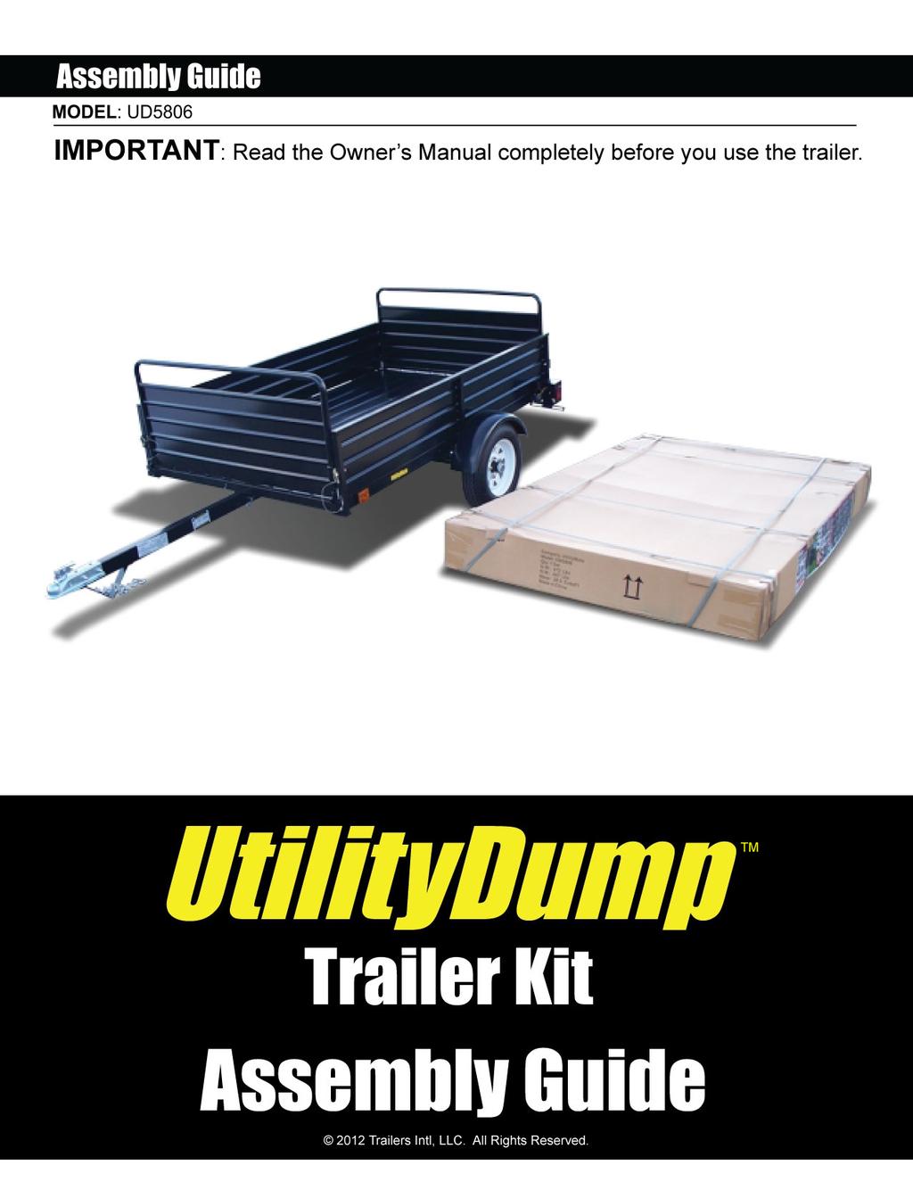
2 At-A-Glance Trailer Assembly Overview VERY IMPORTANT; ALWAYS REFER TO YOUR OWNER S MANUAL FOR PROPER OPERATING AND SAFETY INFORMATION REGARDING YOUR TRAILER. INCASE OF LOSS GO TO BEFORE & AFTER PICTURE REMOVE PARTS & FLIP FRAME METRIC TOOLS (not supplied) U Bolt Blister & Bolt Blister Step By Step Assembly Overview 1. STEP 1; Read owner s manual & refer to it during assembly. 2. STEP 2; Open & remove all parts from on top of the trailer frame. 3. STEP 3; Flip the trailer frame upside down for assembly. 4. STEP 4; Gather the metric tools required to assemble the trailer. 11mm, 13mm, 17mm, 19mm, 21mm, 24mm sockets w/ extension 11mm, 13mm, 17mm, 19mm, 24mm open end wrench(s) Locate the bolt Blister & U bolt Blister from parts, put in secure spot for assembly - 1 -


 3 ¼ long bolts, washers and lock nuts that fasten the coupler to the tongue are")

3 Tongue Assembly Checklist ATTACH TONGUE MOUNT TO FRAME ATTACH PIVOT BOLT & L PIN TO FRAME ATTACH 12V TONGUE & FRAME PLUG CHECK COUPLER, SAFETY CHAINS STEP 5: Tongue Assembly Lay the tongue into load bearing guide, making sure the tongue stand is pointed upward and it is out past the front of the trailer frame. Use the 24mm ratchet & open end wrench to attach the 4 ½ pivot bolt and lock nut to the back of the tongue mount. Slide the removable L pin through the front of the tongue mount hole and tongue hole, then secure the L pin using the carter pin provided. STEP 6: Connect the 12v tongue wire plug into the 12v trailer frame wire plug. STEP 7: Use the 20mm ratchet & open end wrench to CHECK and make sure that the (2) 3 ¼ long bolts, washers and lock nuts that fasten the coupler to the tongue are securely tightened. Use the 17mm ratchet & open end wrench to CHECK and make sure that the 1½ long bolts, washers and lock nuts to mount the safety chains to the V stand on the tongue are securely tightened. Bolt heads are to be located on the outside of the V stand. The bolt is slid through the last chain link on the inside of the V stand and secured tightly with a lock nut. For Safety Purpose Please Check the Bolts to Insure That Secure the Coupler and Safety Chains to the Tongue are Properly Tightened: - 2 -


 to see what the finished axle assembly should look at once mounted properly.")

4 Axle, Spring, Fender Assembly AXLE, SPRINGS, TIRES, FENDERS ATTACH SPRING & FENDER (3) ATTACH AXLE TO SPRING SET (4) FENDER, SPRING, AXLE MOUNT STEP 8: Lay slipper springs in spring track with spring eye facing towards front of trailer frame and the spring slipper facing the rear of the trailer. Use the 22mm ratchet & open end wrench to attach the bolt through the spring eye to the frame. STEP 9: Attach the axle to the springs - using the U Bolts as shown in picture (3). The springs have a male nub which will match up to the female nub hole on the axle. Make sure the male nub is in the female nub hole before mounting the U Bolts. Use the 17mm ratchet to attach and securely tighten the U Bolts to the axle and springs. Refer to photo (4) to see what the finished axle assembly should look at once mounted properly. STEP 10: The fenders are universal and can be mounted on either side - Use the 14mm ratchet & open end wrench to attach and securely tighten the (4) 3½ long bolts, washers and lock nuts that fasten & attach the springs and fenders to the trailer frame. STEP 11: Tire / Wheel Assembly Remove the wheel lug nuts from the hubs, and slide the complete tire/wheel assemblies as received with valve stems facing outward on the lugs on the hubs, then use the wheel lug nuts first removed to properly secure the tire/wheel assemblies onto the hubs with ft-lb torque. Use the 19mm ratchet with extension to secure lug nuts


5 Step 12 Light Assembly Checklist REAR LIGHT ASSEMBLY PLUG & PLAY CONNECTORS SIDE MARKERS ARE INSTALLED PROPER REAR LIGHT MOUNT Identify which light is the right side and left side by looking at the bottom of the lights. The left light (driver s side) has a clear lens in the bottom for the illumination of a license plate with the License Plate bracket attached. Rear LED Light Assembly Use a 13mm ratchet or open end wrench to attach rear light protectors to the frame as shown above pictures. The tail lights are plug & play, locate the wire harness for the rear lights on the frame and plug in the connector from the lights into the wire harness on the trailer frame as shown above. Proper Rear Light Mount Please review the (4) picture above, the metal light protectors have (2) bolts that are already attached that mount to the pre drilled holes at the back of the frame. LED Side Markers - Use a small Phillips screw driver and a 7mm ratchet or open end wrench to attach side markers to the frame as shown below. Please review the (3) picture above to make sure the side markers are mounted as shown. The side markers are plug & play. Locate the wire harness for the side markers on the frame and plug in the connectors from the lights into the harness
 strong bodied people, safely flip the trailer over by standing the trailer on end (its rear frame) and carefully flipping it")
 Enough man power that can SAFELY handle the weight of the trailer when flipping it over.")


6 FLIP TRAILER, INSTALL SIDES, FINAL CHECK SAFELY FLIP TRAILER UPRIGHT ATTACH SIDES & DROP GATES CHECK DUMP FUNCTION ATTACH VIN TAG & TIRE LABEL STEP 13: USE EXTREME CAUTION: Using at least (2) strong bodied people, safely flip the trailer over by standing the trailer on end (its rear frame) and carefully flipping it over to support itself on the wheels and the tongue stand. Do not attempt this if you do not have; 1.) Adequate clearance above and from side to side or 2.) Enough man power that can SAFELY handle the weight of the trailer when flipping it over. STEP 14: Use the 13mm ratchet & open end wrench to attach and securely tighten the (6) 2 ½ long bolts, washers and lock nuts that fasten the SIDE PANELS to the trailer frame. STEP 15: Use the 19mm ratchet & open end wrench to attach and securely tighten the (4) 3 long bolts, washers and lock nuts that fasten the front & back DROP GATES to the trailer frame. STEP 16: Apply VIN Tag & Tire Placard, mount the side markers, by law the labels must be mounted on the driver s side. The best placement for the labels is on the driver s side of the tongue. VERY IMPORTANT: With your OWNER S MANUAL in hand, completely go over your trailer completely and make sure YOU properly installed all parts and that they are working correctly
UtilityMate Trailer Kit Assembly Guide
 ASSEMBLY GUIDE MODELS UM5806 AND 5288 IMPORTANT: Read the Owner s Manual completely before you use the trailer. UtilityMate Trailer Kit Assembly Guide At-A-Glance Trailer Assembly Overview 1. 2. 3. 1.
3 MULTI PURPOSE TRAILER KIT ASSEMBLY GUIDE. Free Call
 ASSEMBLY GUIDE MODEL: AT6096G WARNING: Read and understand the owner's manual completely before you use the trailer. 3 MULTI PURPOSE TRAILER KIT ASSEMBLY GUIDE SAVE THIS GUIDE & MANUAL You will need this
SUT-450-I ASSEMBLY REQUIREMENTS
 SUT-450-I Torque wrench, carpenters square, wire cutters, Phillips screwdriver, 7/16, 9/16, and 3/4 combination wrenches, ratchet, 9/16,3/4,13/16, and 7/8 sockets. ASSEMBLY REQUIREMENTS *Torque all T-bolt
ST - HD - HDXL Model
 ST - HD - HDXL Model TOOLS REQUIRED FOR ASSEMBLY OF THE TANDEM TOW DOLLY Ratchet Socket Wrench with sockets sizes: 7/16, 9/16, 3/ 4 & 15/16 7/16 Box or Open End Wrench 9/16 Box or Open End Wrench 3/4 Box
Read the owner s manual completely before you use the trailer.
 OWNER S MANUAL Read the owner s manual completely before you use the trailer. MODEL MPT-UM6096 IMPORTANT SAFETY CHECK LIST PLEASE NOTE: Trailers are not generally used every day. A trailer may sit for
Read the owner s manual completely before you use the trailer.
 OWNER S MANUAL Read the owner s manual completely before you use the trailer. MODEL MPT-581ATV IMPORTANT SAFETY CHECK LIST PLEASE NOTE: Trailers are not generally used every day. A trailer may sit for
SUT-250-S (These instructions are used for SUT-250-SCLC also)
") SUT-250-S (These instructions are used for SUT-250-SCLC also) Torque wrench, carpenters square, wire cutters, Phillips screwdriver, 7/16, 9/16, and 3/4 combination wrenches, ratchet, 9/16, 3/4, 13/16,
SUT-250-S (These instructions are used for SUT-250-SCLC also) Torque wrench, carpenters square, wire cutters, Phillips screwdriver, 7/16, 9/16, and 3/4 combination wrenches, ratchet, 9/16, 3/4, 13/16,
Trailer Assembly Guide Model MMT5X GVWR All Steel Trailer
 DETAIL K2 INC. 1080 Clay Ave., Unit #2 Burlington Ont. L7L 0A1 1-888-277-6960 Trailer Assembly Guide Model MMT5X7 2050 GVWR All Steel Trailer 7.5 ft. (229 cm) Utility Trailer MMT5X7 man v.160328 STEP 1
NORTHSTAR TRAILERS. Assembly Guide for MULTISTAR Trailer
 NORTHSTAR TRAILERS Assembly Guide for MULTISTAR Trailer Congratulations! You are the proud owner of a NORTHSTAR trailer. Please follow the instructions and steps in this manual for proper assembly. TRAILER
NORTHSTAR TRAILERS. Assembly Guide for SPORTSTAR I Trailer
 NORTHSTAR TRAILERS Assembly Guide for SPORTSTAR I Trailer Congratulations! You are the proud owner of a NORTHSTAR trailer. Please follow the instructions and steps in this manual for proper assembly. We
UNPACK AND IDENTIFY THE FOLLOWING PARTS.
 SUT-250-M2 ASSEMBLY REQUIREMENTS *Torque all T-bolt nuts to 35-40 foot pounds. *Check all lights before towing. *Tire pressure not to exceed recommendation on serial tag. *Re-torque wheel nuts after first
<THESE INSTRUCTIONS MUST BE GIVEN TO THE END USER> B&W
 B&W Trailer Hitches 1216 Hawaii Rd / PO Box 186 Humboldt, KS 66748 Turnoverball Gooseneck Hitch Installation Instructions MODEL 1314 2013 2014 RAM 3500
Truck Owner. Heavy Vehicle Inspection Checklist. conducted for. Location Kidman Way, Mount Hope NSW 2877, Australia. Conducted on 27 Mar :07 AM
 Heavy Vehicle Inspection Checklist conducted for Truck Owner Location Kidman Way, Mount Hope NSW 2877, Australia Conducted on 27 Mar 2018 09:07 AM Prepared by SafetyCulture Staff Completed on 27 Mar 2018
<THESE INSTRUCTIONS MUST BE GIVEN TO THE END USER> B&W
 B&W Trailer Hitches 1216 Hawaii Rd / PO Box 186 Humboldt, KS 66748 P:620.473.3664 F:620.869.9031 Turnoverball Gooseneck Hitch Installation Instructions
NORTHSTAR TRAILERS. Assembly Guide for SPORTSTAR II Trailer
 NORTHSTAR TRAILERS Assembly Guide for SPORTSTAR II Trailer Congratulations! You are the proud owner of a NORTHSTAR trailer. Please follow the instructions and steps in this manual for proper assembly.
SAFETY. Read and understand all safety precautions and instructions before installing this product.
 SAFETY Your safety and the safety of others is very important. In order to help you make informed decisions about safety, we have provided installation instructions and other information. These instructions
AutoFarm GPS AutoSteer Hardware Installation Guide
 AutoFarm GPS AutoSteer Hardware Installation Guide Supported Models: John Deere 7220 John Deere 7320 John Deere 7420 John Deere 7520 PN: 602-0022-02 Special Requirements Tools This list consists of special
UNPACK AND IDENTIFY THE FOLLOWING PARTS.
 SUT-350-AIT ASSEMBLY REQUIREMENTS *Torque all T-bolt nuts to 35-40 foot pounds. *Check all lights before towing. *Tire pressure not to exceed recommendation on serial tag. *Re-torque wheel nuts after first
<THESE INSTRUCTIONS MUST BE GIVEN TO THE END USER> B&W Trailer Hitches 1216 Hawaii Rd / PO Box 186 Humboldt, KS P: F:
 B&W Trailer Hitches 6 Hawaii Rd / PO Box 86 Humboldt, KS 6678 P:60.7366 F:60.73766 Turnoverball Gooseneck Hitch Installation Instructions MODEL 38 0 06
<THESE INSTRUCTIONS MUST BE GIVEN TO THE END USER> B&W
 B&W Trailer Hitches 1216 Hawaii Rd / PO Box 186 Humboldt, KS 66748 P:620.473664 F:620.869.9031 Turnoverball Gooseneck Hitch Installation Instructions
INSTALLATION INSTRUCTIONS
 INSTALLATION INSTRUCTIONS OUTLAW REAR BUMPER APPLICATION: 2016-2018 Chevrolet Silverado 1500 PART NUMBER: 58-81005 CONTENT ITEM QUANTITY DESCRIPTION TOOLS NEEDED 1 1 REAR BUMPER 18MM WRENCH 2 4 SENSOR
<THESE INSTRUCTIONS MUST BE GIVEN TO THE END USER> B&W
 B&W Trailer Hitches 6 Hawaii Rd / PO Box 86 Humboldt, KS 6678 P:60.7366 F:60.86.03 Turnoverball Gooseneck Hitch Installation Instructions MODEL 38 0 08
JEEP JL 2018 License Plate Relocation Bracket
 921105340 JEEP JL 2018 License Plate Relocation Bracket Thank you for choosing Rough Country for all your vehicle needs. Please read instructions before beginning installation. Check the kit hardware against
PDF created with pdffactory trial version
 J 4628 MH 0-5-08 H 458 MH 05-2-08 DWG. REV. ECR/NDR NUMBER REVISED BY DATE 0-02 REPLACED 0-02205 (" TIRES); 0-02 REPLACED 0-02252 (4" TIRES); 00-0900 REPLACED 00-00999 0-069 WAS 0-0228.X 0.00.XXXX 0.00-2-06
PLEASE READ THIS INSTRUCTIONS CAREFULLY, BEFORE YOU START INSTALLATION
 INSTALLATION INSTRUCTIONS PART NUMBER: L0SXC000 DESCRIPTION: 09 ASCENT TRAILER HITCH PLEASE READ THIS INSTRUCTIONS CAREFULLY, BEFORE YOU START INSTALLATION SAFETY PRECAUTION: When installing Trailer Hitch,
SAFETY THIS PRODUCT IS FOR OFFROAD USE ONLY. ALL LIABILITY FOR INSTALLATION AND USE RESTS WITH THE OWNER.
 SAFETY Your safety and the safety of others is very important. In order to help you make informed decisions about safety, we have provided installation instructions and other information. These instructions
SAFETY. Read and understand all safety precautions and instructions before installing this product.
 SAFETY Your safety and the safety of others is very important. In order to help you make informed decisions about safety, we have provided installation instructions and other information. These instructions
UNPACK AND IDENTIFY THE FOLLOWING PARTS.
 SUT-500-S ASSEMBLY REQUIREMENTS *Torque all T-bolt nuts to 35-40 foot pounds. *Check all lights before towing. *Tire pressure not to exceed recommendation on serial tag. *Re-torque wheel nuts after first
SAFETY THIS PRODUCT IS FOR OFFROAD USE ONLY. ALL LIABILITY FOR INSTALLATION AND USE RESTS WITH THE OWNER.
 SAFETY Your safety and the safety of others is very important. In order to help you make informed decisions about safety, we have provided installation instructions and other information. These instructions
<THESE INSTRUCTIONS MUST BE GIVEN TO THE END USER> B&W
 B&W Trailer Hitches 6 Hawaii Rd / PO Box 86 Humboldt, KS 66748 P:60.473664 F:60.869.903 Turnoverball Gooseneck Hitch Installation Instructions MODEL 08
INSTALLATION INSTRUCTIONS
 INSTALLATION INSTRUCTIONS OUTLAW REAR BUMPER APPLICATION: 2013-2018 Dodge Ram 1500 PART NUMBER: 58-81025 CONTENT ITEM QUANTITY DESCRIPTION TOOLS NEEDED 1 1 REAR BUMPER 18MM WRENCH 2 4 SENSOR L-TAB 5MM
SAFETY THIS PRODUCT IS FOR OFFROAD USE ONLY. ALL LIABILITY FOR INSTALLATION AND USE RESTS WITH THE OWNER.
 SAFETY Your safety and the safety of others is very important. In order to help you make informed decisions about safety, we have provided installation instructions and other information. These instructions
UT ASSEMBLY REQUIREMENTS. *Torque all T-bolt nuts to foot pounds.
 UT-1000-8-04 ASSEMBLY REQUIREMENTS *Torque all T-bolt nuts to 35-40 foot pounds. *Check all lights before towing. *Tire pressure not to exceed recommendation on serial tag. *Re-torque wheel nuts after
INSTALLATION LIGHTED CURVED LAY DOWN LICENSE PLATE MOUNT 3166
 INSTALLATION LIGHTED CURVED LAY DOWN LICENSE PLATE MOUNT 3166 PARTS INCLUDED 1 Lighted Curved Lay Down License Plate Assembly 1 Hardware Kit Including: 6 Cable Ties 1 Dielectric Grease Pack 1 1 x 8 Tape
SLR WHEEL KIT P/N APPLICATION BEFORE YOU BEGIN DISCLAIMER ACCESSORY WEIGHT KIT CONTENTS. Instr Rev Page 1 of 6.
 SLR WHEEL KIT P/N 2882340 APPLICATION Slingshot BEFORE YOU BEGIN Read these instructions and check to be sure all parts and tools are accounted for. Please retain these installation instructions for future
<THESE INSTRUCTIONS MUST BE GIVEN TO THE END USER> B&W Trailer Hitches 1216 Hawaii Rd / PO Box 186 Humboldt, KS P: F:
 B&W Trailer Hitches 26 Hawaii Rd / PO Box 86 Humboldt, KS 66748 P:620.473664 F:620.869.903 Turnoverball Gooseneck Hitch Installation Instructions Mounting
INSTALLATION INSTRUCTIONS TRAILER HITCH MAIN HARNESS KIT
 PART NUMBER: 0000-89-N30 GENUINE ACCESSORIES INSTALLATION INSTRUCTIONS TRAILER HITCH MAIN HARNESS KIT APPLICABLE MODELS: 2016 > CX-9 PACKAGE CONTENTS: INSTALLATION INSTRUCTIONS QTY 1 CABLE TIE MOUNT QTY
Installation Instructions Tacoma/Tundra P/N s TY80007, TY80008, TY80013, TY80016
 Patent # US 7,100,956 BA Installation Instructions Tacoma/Tundra P/N s TY80007, TY80008, TY80013, TY80016 CAUTION IT IS NOT RECOMMENDED MOUNTING THE TIREGATE ON TRUCKS THAT HAVE REAR FIBER GLASS REPLACEMENT
*Phillips Screwdriver *10mm Nut Driver *10mm Socket *Ratchet *Three Inch Putty Knife *Panel Removal Tool *10mm Wrench CONTENTS:
 TOOLS REQUIRED: *Phillips Screwdriver *10mm Nut Driver *10mm Socket *Ratchet *Three Inch Putty Knife *Panel Removal Tool *10mm Wrench CONTENTS: 1EA. SUBWOOFER ASSEMBLY 1EA. 100 WATT AMP ASSEMBLY 1EA. WIRE
<THESE INSTRUCTIONS MUST BE GIVEN TO THE END USER> B&W Trailer Hitches 1216 Hawaii Rd / PO Box 186 Humboldt, KS P: F:
 B&W Trailer Hitches 26 Hawaii Rd / PO Box 86 Humboldt, KS 66748 P:620.473664 F:620.473766 Turnoverball Gooseneck Hitch Installation Instructions Mounting
Procedure to Release Stored Energy in Front-to-Back Systems Prior to Service
 Procedure to Release Stored Energy in Front-to-Back Systems Prior to Service Roll Rite, LLC and its entire staff would like to Thank You for your purchase of one of what we feel to be the finest line of
INSTALLATION INSTRUCTIONS
 INSTALLATION INSTRUCTIONS ----1075 North Ave. Sanger, CA 93657-3539 toll free: 800-445-3767 web: www.belltechcorp.com---- 5052 AIR JACK 94-99 DODGE ½ TON RAM C-1500 Congratulations! You were selective
C44090 HP325 PACBRAKE COMPRESSOR CONVERSION
 C44090 HP325 PACBRAKE COMPRESSOR CONVERSION APPLICATIONS: DODGE 2003-2007 5.9L CUMMINS Compressor Replacement Instructions for C14030, C14045, C44030, C44045, C44049 & C44052 with Air Tank KIT CONTENTS
** DO NOT EXCEED THE RECOMMENDED VEHICLE TOWING WEIGHT RATING ** DODGE RAM 1500
 10/3/2017 DODGE RAM 1500 WARNING!! BRAKE, FUEL, AND ELECTRICAL LINES MAY NEED TO BE LOOSENED OR REPOSITIONED TO PROVIDE CLEARANCE FOR NEW HARDWARE. ON SHORT BED MODELS, CHECK FOR ADEQUATE TURNING CLEARANCE
HAVING INSTALLATION QUESTIONS? CALL TECHNICAL SUPPORT AT
 9/23/2009 1 of 6 ITEM 1 QTY 8 Parts List PART NUMBER DESCRIPTION 3/8" CONICAL TOOTHED WASHER TOOLS REQUIRED #2 PHILLIPS SCREWDRIVER #2 STUBBY SCREWDRIVER 8mm SOCKET 13mm SOCKET RATCHET 12" EXTENSION TORQUE
PLEASE READ THESE INSTRUCTIONS CAREFULLY, BEFORE YOU START INSTALLATION
 PART NUMBER: L0SSJ000 INSTALLATION INSTRUCTIONS DESCRIPTION: FORESTER TRAILER HITCH PLEASE READ THESE INSTRUCTIONS CAREFULLY, BEFORE YOU START INSTALLATION SAFETY PRECAUTION: When installing Trailer Hitch,
Fast Master Products, Inc. P.O. Box 654, Katy Texas Tel: (281) Fax: (281)
 Fax: (281)") Fast Master Products, Inc. P.O. Box 654, Katy Texas 77492-0654 Tel: (281) 391-6750 Fax: (281) 391-6760 Email: info@cruiserlift.com Easy installation and removal from the pick-up bed. Compatible with all
Fast Master Products, Inc. P.O. Box 654, Katy Texas 77492-0654 Tel: (281) 391-6750 Fax: (281) 391-6760 Email: info@cruiserlift.com Easy installation and removal from the pick-up bed. Compatible with all
NXG-65 / NXG-70 / NXG-80. Deck Post & Tilt Mount Assembly Manual
 NXG-65 / NXG-70 / NXG-80 Deck Post & Tilt Mount Assembly Manual Table of Contents DECK POST INSTALLATION... 5 PARTS FOR POST ASSEMBLY... 5 TILT MOUNTS... 6 POST TO PLATE ASSEMBLY... 7 PLATE POSITION AND
Trailer Parts. Brake Components. Axle Components. Suspensions. Lights & Electrical. Wheels & Tires. Loading Ramps. Couplers & Safety Chains
 Trailer Parts Brake Components Axle Components Suspensions Lights & Electrical Wheels & Tires Loading Ramps Couplers & Safety Chains Trailer Jacks Fenders Dump Trailer Parts Tilt SST Parts Decal Kits Brake
UTILITY TRAILERS. Above The Rest
 UTILITY TRAILERS FT7716 Above The Rest 7712 77X12 (2,990 lbs GVWR) S/A Rail shown with mesh gate and 2 high sides options 1 Key Points To Remember About Doolittle Trailers Standard Features New Tires Safety
SAFETY THIS PRODUCT IS FOR OFFROAD USE ONLY. ALL LIABILITY FOR INSTALLATION AND USE RESTS WITH THE OWNER.
 SAFETY Your safety and the safety of others is very important. In order to help you make informed decisions about safety, we have provided installation instructions and other information. These instructions
Rolling Work Seat
 108681 Rolling Work Seat 12855 2012 FarmTek All Rights Reserved. Reproduction is prohibited without permission. STK# DIMENSIONS 108681 14 W x 31 L x 18 H 1 REQUIRED TOOLS The following list identifies
SAFETY THIS PRODUCT IS FOR OFFROAD USE ONLY. ALL LIABILITY FOR INSTALLATION AND USE RESTS WITH THE OWNER.
 SAFETY Your safety and the safety of others is very important. In order to help you make informed decisions about safety, we have provided installation instructions and other information. These instructions
2015+ Mustang Rear Valance Installation Instructions P/N: (R F953) (R F953BS)
 (R F953BS)") 2015+ Mustang Rear Valance Installation Instructions P/N: 421894 (R1315-17F953) 421919 (R1315-17F953BS) 39555 Schoolcraft Rd, Plymouth MI, 48170 800.59.ROUSH 2015+ Mustang Rear Valance Kit Installation
2015+ Mustang Rear Valance Installation Instructions P/N: 421894 (R1315-17F953) 421919 (R1315-17F953BS) 39555 Schoolcraft Rd, Plymouth MI, 48170 800.59.ROUSH 2015+ Mustang Rear Valance Kit Installation
SAFETY THIS PRODUCT IS FOR OFFROAD USE ONLY. ALL LIABILITY FOR INSTALLATION AND USE RESTS WITH THE OWNER.
 SAFETY Your safety and the safety of others is very important. In order to help you make informed decisions about safety, we have provided installation instructions and other information. These instructions
AutoFarm GPS AutoSteer Hardware Installation Guide
 AutoFarm GPS AutoSteer Hardware Installation Guide Supported Models: Case AFX-8010 Combines PN: 602-0039-01-A Special Requirements Tools This list consists of special tools required to complete the installation.
LoD Offroad. Jeep JK Door Linked Rear Bumper with Tire Carrier Installation Instructions
 LoD Offroad Jeep JK Door Linked Rear Bumper with Tire Carrier Installation Instructions Please read through the instructions before beginning any part of the installation process. Packaging List: 1-Rear
*Phillips Screwdriver *10mm Nut Driver *8mm Nut Driver*10mm Socket *Ratchet *Three Inch Putty Knife*Panel Removal Tool *10mm Wrench
 TOOLS REQUIRED: *Phillips Screwdriver *10mm Nut Driver *8mm Nut Driver*10mm Socket *Ratchet *Three Inch Putty Knife*Panel Removal Tool *10mm Wrench CONTENTS: 1EA. SUBWOOFER ASSEMBLY P/N 05030280AA 1EA.
Hayes TrailTrac Kit Installation Guidelines Polaris Rush / Pro-R / Indy
 Models: 2010-2014 Polaris Rush / Pro-R / Indy Packing List 1 Electronic Control Unit (ECU) 1 ECU Velcro, 3 inch 1 Switch face plate 1 Switch face plate adhesive 1 Switch 1 Wiring harness 1 Fully pre-filled
INSTALLATION INSTRUCTIONS
 INSTALLATION INSTRUCTIONS ----1075 North Ave. Sanger, CA 93657-3539 toll free: 800-445-3767 web: www.belltechcorp.com---- 5001 AIRJACK AIR SPRING SUSPENSION SYSTEM C 1500 AND C-2500 Congratulations! You
SAFETY. Injury hazard
 SAFETY Your safety and the safety of others is very important. In order to help you make informed decisions about safety, we have provided installation instructions and other information. These instructions
2800 VIBRO-TILL FIELD CULTIVATOR ASSEMBLY INSTRUCTIONS Series. Kongskilde
 2800 VIBRO-TILL FIELD CULTIVATOR Kongskilde 2800 Series *Model may not be exactly as shown. Kongskilde reserves the right to make changes to product designs and specifications without notice or obligation
INSTALLATION INSTRUCTIONS
 INSTALLATION INSTRUCTIONS WARNING: NEVER EXCEED YOUR VEHICLE MANUFACTURER'S RECOMMENDED TOWING CAPACITY PIN-STYLE TRUNNION BAR WEIGHT DISTRIBUTION KIT MAINTENANCE Keep the socket-mounted ends of the spring
Trailer Parts. Brake Components. Axle Components. Suspensions. Lights & Electrical. Wheels & Tires. Loading Ramps. Couplers & Safety Chains
 Trailer Parts Brake Components Axle Components Suspensions Lights & Electrical Wheels & Tires Loading Ramps Couplers & Safety Chains Trailer Jacks Fenders Dump Trailer Parts Tilt SST Parts Decal Kits Brake
SAFETY SENSORS FIELD OF VIEW WILL BE ALTERED WITH USE OF THE REPLACEMENT BUMPER. Injury hazard
 SAFETY Your safety and the safety of others is very important. In order to help you make informed decisions about safety, we have provided installation instructions and other information. These instructions
MAINTENANCE WEIGHT RATINGS WARNINGS. warning: never exceed your vehicle manufacturer's recommended towing capacity
 Installation instructions warning: never exceed your vehicle manufacturer's recommended towing capacity Pin-style trunnion Bar WEIGHT DISTRIBUTION MAINTENANCE Keep the socket-mounted ends of the spring
SAFETY THIS PRODUCT IS FOR OFFROAD USE ONLY. ALL LIABILITY FOR INSTALLATION AND USE RESTS WITH THE OWNER.
 SAFETY Your safety and the safety of others is very important. In order to help you make informed decisions about safety, we have provided installation instructions and other information. These instructions
ASSEMBLY MANUAL. 45-Foot Air Double Disc Drill. Amity Technology, LLC th Avenue North Fargo, ND (701)
") ASSEMBLY MANUAL 45-Foot Air Double Disc Drill Amity Technology, LLC 2800 7th Avenue North Fargo, ND 58102 (701) 232-4199 www.amitytech.com TABLE OF CONTENTS Main Frame 1 Wing Lock Towers 3 Wing Frames
ASSEMBLY MANUAL 45-Foot Air Double Disc Drill Amity Technology, LLC 2800 7th Avenue North Fargo, ND 58102 (701) 232-4199 www.amitytech.com TABLE OF CONTENTS Main Frame 1 Wing Lock Towers 3 Wing Frames
SAFETY THIS PRODUCT IS FOR OFFROAD USE ONLY. ALL LIABILITY FOR INSTALLATION AND USE RESTS WITH THE OWNER.
 SAFETY Your safety and the safety of others is very important. In order to help you make informed decisions about safety, we have provided installation instructions and other information. These instructions
SAFETY SENSORS FIELD OF VIEW WILL BE ALTERED WITH USE OF THE REPLACEMENT BUMPER. Injury hazard
 SAFETY Your safety and the safety of others is very important. In order to help you make informed decisions about safety, we have provided installation instructions and other information. These instructions
SAFETY THIS PRODUCT IS FOR OFFROAD USE ONLY. ALL LIABILITY FOR INSTALLATION AND USE RESTS WITH THE OWNER.
 SAFETY Your safety and the safety of others is very important. In order to help you make informed decisions about safety, we have provided installation instructions and other information. These instructions
TOYOTA COROLLA 2010 TVIP V4 PREPARATION
 PREPARATION Part #: PT398-02080 or PT398-02100 NOTE: Part number of this accessory may not be the same as the part number shown. Conflicts: Do not install into Manual Transmission Vehicles or Vehicles
INSTALLATION MANUAL
 INSTALLATION MANUAL 2563000 Parts List 1 Carrier weldment 2 Support arm assembly 1 Third brake light assembly 1 Light extension bracket 1 Spare tire adjustment plate 1 Spare tire mount plate 1 Female spade
VELAR HITCH INSTALLATION INSTRUCTIONS TOW RANGE ROVER MODEL/ TRIM YEARS: WEIGHT CAPACITY to Present PARTS & SUPPLIES: TOOLS REQUIRES:
 HITCH INSTALLATION INSTRUCTIONS MAKE: RANGE ROVER YEARS: 2018 to Present MODEL/ TRIM VELAR PACKAGE: TOW WEIGHT CAPACITY TRAILER TONGUE 5300 LBS. 300 LBS. INSTALLATION TIME: 2 HOURS NO YES YES PARTS & SUPPLIES:
2007 Current Jeep Wrangler JK Stealth Fighter Rear Bumper With Tire Gate Installation Instructions
 2007 Current Jeep Wrangler JK Stealth Fighter Rear Bumper With Tire Gate Installation Instructions PREPARATION 1. Disconnect the negative terminal on the battery. Park the vehicle on level ground and set
SAFETY THIS PRODUCT IS FOR OFFROAD USE ONLY. ALL LIABILITY FOR INSTALLATION AND USE RESTS WITH THE OWNER.
 SAFETY Your safety and the safety of others is very important. In order to help you make informed decisions about safety, we have provided installation instructions and other information. These instructions
LOW MOUNT SPA COVERLIFT Installation Instructions
 LOW MOUNT SPA COVERLIFT Installation Instructions IMPORTANT!! READ ALL INSTRUCTIONS CAREFULLY BEFORE BEGINNING INSTALLATION ITEM NUMBER: NP5022 Mfg#3200103 (Spa and Spa Cover Not Included)!! CAUTION!!
GROSS LOAD CAPACITY WHEN USED AS A WEIGHT CARRYING HITCH: 2,000 LBS. TRAILER WEIGHT & 200 LBS. TONGUE WEIGHT.
 PAGE 1 0F 6 GROSS LOAD CAPACITY WHEN USED AS A WEIGHT CARRYING HITCH: 2,000 LBS. TRAILER WEIGHT & 200 LBS. TONGUE WEIGHT. WARNING: ALL NON-TRAILER LOADS APPLIED TO THIS PRODUCT MUST BE SUPPORTED BY 18050
SAFETY. Read and understand all safety precautions and instructions before installing this product.
 SAFETY Your safety and the safety of others is very important. In order to help you make informed decisions about safety, we have provided installation instructions and other information. These instructions
KIT No , and 80590
 KIT No. 80531, 80545 and 80590 by MN-354 (05603) ECR 5593 Please read these instructions completely before proceeding with installation Air Spring Kit Parts List Item Description Quantity A Air Spring
SAFETY SENSORS FIELD OF VIEW WILL BE ALTERED WITH USE OF THE REPLACEMENT BUMPER. Injury hazard
 SAFETY Your safety and the safety of others is very important. In order to help you make informed decisions about safety, we have provided installation instructions and other information. These instructions
TOYOTA VENZA w/smart 2009 TVIP V4 PREPARATION
 PREPARATION Part #: PT398-0T110 Conflicts: Will not program with Techstream Lite. Kit Contents RES ECU RES ECU Bracket RES Harness M6 Screw Wire Tie Splicing Connector Remote Label x1 x1 x1 x1 x5 x1 x2
Installation Instructions
 Installation Instructions GOOSENECK MOUNTING KIT Ford Super Duty F-250/F-350/ F-450 Part Numbers: 4494 WARNING: Under no circumstances do we recommend exceeding the towing vehicle manufacturers recommended
SAFETY THIS PRODUCT IS FOR OFFROAD USE ONLY. ALL LIABILITY FOR INSTALLATION AND USE RESTS WITH THE OWNER.
 SAFETY Your safety and the safety of others is very important. In order to help you make informed decisions about safety, we have provided installation instructions and other information. These instructions
KARAVAN T R A I L E R S
 C 0 MJH B 036 KMH 06--2 04-0-0 ADDED (4)2-0036. REPLACED 8-0003 WITH 8-00049; -0002 WITH -00 - (2X); -00046 WITH -00330; -0004 WITH -0006; -00048 WITH -0006.X 0.00.XXXX 0.00 OF NOTES:.) WINCH SHOULD BE
PART NUMBER: E361SAJ400
 A KIT CONTENTS: Do not use this product with hitch extenders. PIVOT BOLT (1X) PIVOT WASHER (2X) PIVOT NUT (1X) HITCH BOLT (1X) LOCK WASHER (1X) WASHER(1X) SAFETY CLIP (1X) STRAP (6X) BASE (1X) LOCKING
11068 INSTALLATION INSTRUCTIONS
 11068 INSTALLATION INSTRUCTIONS Safety glasses should be worn at all times while installing this product. YEARS: 009-PRESENT MAKE: INFINITI MODEL: G37 & Q60 POWER RETRACTABLE HARD TOP STYLE: CONVERTIBLE
IVTM Installation Manual
 Integrated Vehicle Tire Pressure Monitoring IVTM Installation Manual 2nd edition Copyright WABCO 2006 Vehicle Control Systems An American Standard Company The right of amendment is reserved Version 002/06.06(us)
SAFETY THIS PRODUCT IS FOR OFFROAD USE ONLY. ALL LIABILITY FOR INSTALLATION AND USE RESTS WITH THE OWNER.
 SAFETY Your safety and the safety of others is very important. In order to help you make informed decisions about safety, we have provided installation instructions and other information. These instructions
MAINTENANCE WEIGHT RATINGS WARNINGS. warning: never exceed your vehicle manufacturer's recommended towing capacity
 Installation instructions warning: never exceed your vehicle manufacturer's recommended towing capacity Round Bar WEIGHT DISTRIBUTION kit MAINTENANCE Keep the socket-mounted ends of the spring bars and
Current Ford F150 Race Series R Rear Bumper Installation Instructions
 2015 - Current Ford F150 Race Series R Rear Bumper Installation Instructions PREPARATION STEPS 1. Disconnect the negative terminal on the battery. Park the vehicle on level ground and set the emergency
TOYOTA RAV4 w/smart 2009 TVIP V4 PREPARATION
 PREPARATION Part #: PT398-42110 Conflicts: Do not install into Vehicles manufactured from November 2012 and Onwards. Kit Contents RES ECU Gateway ECU RES ECU Bracket Gateway ECU Bracket Remote Label Key
SAFETY THIS PRODUCT IS FOR OFFROAD USE ONLY. ALL LIABILITY FOR INSTALLATION AND USE RESTS WITH THE OWNER.
 SAFETY Your safety and the safety of others is very important. In order to help you make informed decisions about safety, we have provided installation instructions and other information. These instructions
Installation Instructions Dodge Ram P/N D80014
 Patent # US 7,100,956 BA Installation Instructions Dodge Ram 94-01 P/N D80014 CAUTION IT IS NOT RECOMMENDED MOUNTING THE TIREGATE ON TRUCKS THAT HAVE REAR FIBER GLASS REPLACEMENT FENDERS. THE BED DOES
R O A D S M I T H TRIKE CONVERSIONS BY THE TRIKE SHOP
 R O A D S M I T H TRIKE CONVERSIONS BY THE TRIKE SHOP Please thoroughly review the instructions before and during installation. Keep in mind that this product was designed to be installed by trained dealer
Installation Instructions Table of Contents
 Installation Instructions Table of Contents Pre- Installation of Garage Storage Lift 2 Layout the Garage Storage Lift 3 Installing the strut Channels 3 Install the Drive Assembly 5 Install the Drive Shaft