EagleMotorsports.com Dear Valued Customer,
|
|
|
- James Edwards
- 5 years ago
- Views:
Transcription
1
2
3 Dear Valued Customer, Thank you for choosing the Stallard brand and establishing this partnership. We appreciate the opportunity to assist you and look forward to promoting your future success. The staff at EMi takes great pride in the products and services we provide and looks forward to delivering you exceptional customer service. We are very proud to have your team as part of the EMi family. In this manual you will be given detailed instruction on assembling your new Stallard SST chassis. Questions not answered in the manual can be directed to EagleMotorsports.com or by calling our offices at Office hours are 8:00 a.m. to 5:00 p.m. central time, Monday through Friday. Our goal is to keep things easy and simple, so please feel free to give our team a call. Thank you for choosing EMi for your racing needs. Office: (toll free) or Fax: accounts@eaglemotorsports.com EagleMotorsports.com iii


4 CHASSIS FEATURES:»» Changed tubing size and thickness to save weight»» New internal bracing for added strength and safety»» Improved front-to-rear weight transfer with a new adjusted spring base»» Modified pickup points to improve traction and forward drive»» Adjusted rack heights for front and rear end stability and improved rear drive»» New sprint car style, stand up radiator design with air induction for economical and efficient cooling»» Simplified floor mount adjustable pedal assembly design»» Right hand shift cable linkage for smoother shifting; natural location allows for safer driver exit»» Standard engine cradle dimension that accommodates most mounts iv EagleMotorsports.com
5 TABLE OF CONTENTS Pedal Installation Steering Installation Front Axle Installation Rear Axle Installation Shifter Assembly Installation Brake Bleeding Procedure Setup Sheet Accessories and Hardware Affiliates Page EagleMotorsports.com


6 PEDAL INSTALLATION: 1 SST BRAKE PEDAL SST THROTTLE PEDAL PEDAL HARDWARE KIT CAM THROTTLE STOP THROTTLE CABLE BRACKET THROTTLE CABLE MASTER CYLINDER BRACKET MASTER CYLINDER /16 FEMALE ROD END T-KIT BRAKE LINE FIGURE A EagleMotorsports.com


 Note that the T-Kit brake line is specifically an INTERNAL brake line, meaning this line will not connect to either caliper.")
7 PEDAL INSTALLATION: Use Figure A in assembly guide for visual assistance on assembly. Pedal assembly is adjustable to aid in finding comfort for any size driver big or small. The SST throttle cable was designed to work with any fuel system, but it is important to note that it will be plenty long for fuel systems that accept the throttle cable to the inside of throttle bodies such as the Engler. If this is the case with your setup, be mindful of the throttle cable when putting the body on. You do not want to get the cable pinched or kinked anywhere, as it will cause a bind and throttle will not function properly. 1) When installing the throttle cable, the 90-degree turn side should go to the throttle cable bracket as shown in Figure A, and the cable should be routed up and over the ignition tray before turning toward the throttle bodies on your fuel system. 2) Note that the T-Kit brake line is specifically an INTERNAL brake line, meaning this line will not connect to either caliper. There is a tab at both the front and rear of the car meant for AN3 bulkheads. The internal line will connect to the master cylinder with a banjo fitting as shown in Figure A, and both remaining ends with 90-degree AN3 fittings will connect to a bulkhead at the front and rear of the car. See Figure B and D. FIGURE B 3) You should have two additional short brake lines to use as external lines running from the bulkhead to the caliper at both the front and rear. If you do not wish to run a left front brake, you can cap the external side of the front bulkhead. See Figure C. FIGURE C 4) Route the long end of the internal line along lower frame rail toward the back of the car. Follow lower rail around engine compartment to the rear halo upright, where you will find the bulkhead tab in the rear of the car. See Figure B and E. 5) The short end of line should be routed straight up to front bulkhead tab, which is located just to the left of the rack and pinion above the steering cross member. See Figure D. FIGURE E NOTE: It is ok to shorten push rod on master cylinder if needed FIGURE D EagleMotorsports.com


 UPPER")


8 STEERING INSTALLATION: MANUAL STEERING 1 RACK AND PINION UPPER STEERING SUPPORT STEERING HUB ASSEMBLY INTERMEDIATE SHAFT STEERING HARDWARE POWER STEERING 1 RACK AND PINION (2) UPPER STEERING SUPPORT STEERING HUB ASSEMBLY INTERMEDIATE SHAFT *POWER STEERING HARDWARE POWER STEERING UNIT EagleMotorsports.com


 Fasten the upper steering support to the race car and")
 Attach the intermediate shaft to the steering hub assembly and jam the set screw on your intermediate shaft u-joint to")


9 STEERING INSTALLATION: When installing your steering, it is easiest to start with the steering support side first. Also note that brand new rack and pinions are sent with the internals coated in an anticorrosive gel that has some adhesive properties. This is to prevent corrosion in storage and chatter in transit. It is important that the rack and pinion is taken apart prior to installation and cleaned thoroughly in a parts washer. Once you have cleaned everything well, manually spread a thin film of grease over rack and pinion gears before reassembling. White lithium or similar lightweight grease is recommended FIGURE A 1) Fasten the upper steering support to the race car and slide the steering hub assembly into the upper steering support. See Figure A. 2) Attach the intermediate shaft to the steering hub assembly and jam the set screw on your intermediate shaft u-joint to prevent the two from separating. See Figure B. FIGURE B 3) Install rack and pinion. It works great to put your 5/ bolts into the rack and pinion first prior to installing it, as the bolts will act as guides when affixing the rack and pinion to the chassis. As you are installing the rack and pinion, you will have to guide the lower u-joint on the intermediate shaft over the input shaft on the rack and pinion as the rack comes to mating point with the chassis. See Figure C. 4) Tighten rack and pinion fasteners prior to jamming the lower u-joint set screw. 5) Tighten and jam set screw on lower u-joint. FIGURE C EagleMotorsports.com
 3/8 X 15 RADIUS RODS 910-351-15 (plain) or 910-3521-15 (black)")
 RH 3/8 ROD ENDS 175-0113 (6) LH 3/8 ROD ENDS 175-0313 (6) RH 3/8 JAM NUTS 175-6043-RH (6) LH 3/8 JAM NUTS")
 LEFT (side view perspective) FIGURE B 5 5/8 6 855.525.")
10 FRONT AXLE INSTALLATION: 1 FRONT AXLE (15 ) or (10 ) 2 (2) SPINDLES (2) STEERING ARMS KING PIN SET FRONT AXLE HARDWARE KIT (4) 3/8 X 15 RADIUS RODS (plain) or (black) 4 (1) 3/8 X 16 RADIUS ROD (plain) or (black) 5 (1) 3/8 STEEL TIE ROD length FIGURE A (6) RH 3/8 ROD ENDS (6) LH 3/8 ROD ENDS (6) RH 3/8 JAM NUTS RH (6) LH 3/8 JAM NUTS LH 6 EMI HUB or ANTI SEIZE TAPE MEASURE (2) 2 SETUP BLOCKS Back of axle tube of,,,,,;ght 5-5/8" 5/8 5 5/8,., IFnmt RIGHT (side view perspective) LEFT (side view perspective) FIGURE B 5 5/ EagleMotorsports.com

 Assemble front axle prior to installation.")

11 FRONT AXLE INSTALLATION: NOTE: Tap all threaded holes on chassis prior to assembly 1) Start by assembling all radius rods. It is important to put anti seize on the threads of all rod ends before assembling radius rods. This will ensure that the rod ends will still be easy to uninstall in the event that rods need to be replaced or adjusted. If you do not use anti seize, the rod ends will lock into place over time due to corrosion and rods will be very difficult to adjust. FIGURE C FIGURE D 2) Assemble front axle prior to installation. When spacing the tie rod and drag link off the steering arms, use ½ spacers out of your front axle hardware kit to put between the arm and drag link as well as between the arm and tie rod on the LF. On the RF, space the tie rod off the steering arm with a ¼ spacer. The reason we use a smaller spacer on the RF is to compensate for the castor split in the axle from right to left. See Figure C and D. 3) Once all radius rods and axle are assembled, square the front axle to ensure that you get your front axle positioned correctly in the car and square. See Figure A a.) Insert assembled Stallard axle and set on 2 blocks b.) Fasten all radius rods to the axle brackets and frame c.) Fasten pan hard bar to axle and frame in center adjustment hole on the frame Measure from outside of frame rail to center of axle bracket Set LF axle bracket to 3 4) Once axle is square, see Figure B and adjust spindle caster: a.) Start with newly squared axle on 2 blocks b.) Level car by placing angle finder on lower frame rail c.) Place an angle finder on the flat of the RF spindle (surface A) where the steering arm connects. Adjust radius rod until you find desired castor setting d.) Double-check axle squareness, re-adjust radius rods to achieve axle squareness with desired caster set FIGURE E 5) When you get to a point where you are ready to attach your drag link to your rack and pinion, note that it is very important to space the rod end on your drag link away from the rack and pinion tab 3/4. The front axle hardware kit you will use for installing the front axle will have extra 3/8 ID spacers for you to use when accomplishing this task. This is important to prevent the drag link from hitting the rack and pinion as the front axle travels through its range of motion. See Figure E. EagleMotorsports.com
12 REAR AXLE INSTALLATION: 1 COMPLETE REAR END ASSEMBLY (1) 7/16 X RADIUS ROD (Plain) or (Black) 2 (1) 7/16 X RADIUS ROD (Plain) or (Black) 3 BRAKE ROD (3) RH 7/16 ROD ENDS (3) LH 7/16 ROD ENDS RH 7/16 JAM NUT PACK RH 5 LH 7/16 JAM NUT PACK LH 6 LR TORSION ARM RR TORSION ARM (2) 4 SETUP BLOCKS ANTI SEIZE TAPE MEASURE ANGLE FINDER REAR ARM FIXTURE (optional) FIGURE A EagleMotorsports.com


 Set your effective arm length This is the distance from the center of the torsion spline to the center of the rod end RR effective length is 11 LR effective arm length is 12.")
13 REAR AXLE INSTALLATION: NOTE: Install and ream all bushings first 1) As instructed previously for front axle installation, start by assembling all radius rods. It is important to put anti seize on the threads of all rod ends before assembling radius rods. This will ensure that the rod ends will still be easy to uninstall in the event that rods need to be replaced or adjusted. If you do not use anti seize, the rod ends will lock into place over time due to corrosion and rods will be very difficult to adjust. 2) See Figure A to get your rear end assembly put together correctly. 3) Once ready to install the rear end assembly, start squaring the axle to get it positioned correctly into the car and square: a.) Set your effective arm length This is the distance from the center of the torsion spline to the center of the rod end RR effective length is 11 LR effective arm length is 12.5 **Torsion arm fixture will aid in quickly and accurately setting effective arm lengths b.) Install axle AFTER spacing properly using Figure A Set axle on 4 blocks Start with both radius rods set in the center adjustment holes on the frame Fasten radius rods, brake rod, and jacob s ladder to axle c.) Time your bird cages and brake carrier Connect torsion arms to bird cages without using torsion stops Time brake carrier so that the brake rod pickup is to the top While using an angle finder, locate 90 on the flat at the front of the birdcage by adjusting the radius rods FIGURE C 4) It is very important that the rear arms are set to the proper effective lengths. This can be accomplished by using a tape measure, but for quicker and more accurate results, we recommend using our rear arm fixture for setting effective arm lengths. Figure C. FIGURE B Radius Rod Radius Rod EagleMotorsports.com

 3/16")


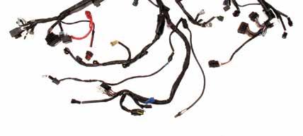
14 SHIFTER ASSEMBLY INSTALLATION: 1 SHIFTER HANDLE SHIFTER CABLE (2) 3/16 FEMALE ROD ENDS CLUTCH LEVER SHIFTER HARDWARE KIT EagleMotorsports.com
 Once completed, use the 3/8 hardware in the shifter hardware kit to attach the handle to the shifter bracket in the race car.")


 The cable should exit the car just in front of the left front radiator upright between the upright and the two-piece")


15 SHIFTER ASSEMBLY INSTALLATION: 1) Start by installing both female rod ends to the ends of the shifter cable. 2) Once completed, use the 3/8 hardware in the shifter hardware kit to attach the handle to the shifter bracket in the race car. See Figure A 3) Next you will install the shift cable, but it is important to notice that both ends of the cable are different lengths. The short end will be the side you want going to your shift handle, and the long end will go to the engine linkage. FIGURE A 4) There is a bracket along the right frame rail just in front of the shift handle you will affix the cable to with the two jam nuts on the cable end. See Figure B. 5) When routing the cable from inside the car out, you should run the cable along the floor toward the left front lower side panel. Depending on where your pedals are mounted, you might run the cable around the pedals or between the pedals. You will want the cable to lay nicely so there is no bind. See Figure C. FIGURE B 6) The cable should exit the car just in front of the left front radiator upright between the upright and the two-piece front scoop. From there the cable will head back toward the engine and affix to the shift cable bracket on the motor mount. The shift cable bracket will be located differently per the engine make being used. If you find that you need additional cable slack, you may reroute the cable behind the radiator upright, but this will require you to notch your left front lower side panel where you would like the cable to exit. See Figure D. 7) Once the cable is affixed to the race car on both ends, use the hardware in your shifter hardware kit to attach the rod ends to both the handle and shift linkage. 8) Finally, adjust the handle position and length of cable ends for driver comfort. FIGURE C FIGURE D EagleMotorsports.com
16 BRAKE BLEEDING PROCEDURE BY A clear brake caliper bleeding tube inserted into the bottom of a bleed bottle should be used for the following steps. Place enough new brake fluid into the bottle to assure that air cannot be drawn into the tube while bleeding. Dual master cylinder application should be bled independently of each other. 1) Start the bleeding process with the caliper furthest from the master cylinder. 2) Loosen or remove the master cylinder cap from the reservoir. 3) Connect the bleed tube to the bleeder screw. If bleeding a caliper with two bleed screws, begin with the bleed screw closest to the wheel. Bleeder screws must point straight up to prevent air from being trapped in the top of the caliper. 4) Slowly pump and hold the brake pedal until the pedal begins to feel solid. Don t allow the fluid level to uncover the opening in the bottom of the reservoir. 5) Open the bleed screw. A small amount of fluid and air should be noticed. Close the bleed screw. 6) Repeat steps 2, 3, and 4 until a large volume of air-free fluid is noticed. 7) Connect the bleed tube to the inboard bleeder; if equipped with two bleeder screws, and repeat the bleeding process. 8) Repeat the bleeding process until all of the calipers are free of air. The last caliper bled should be the closest caliper to the cylinder. 9) Replace and tighten the master cylinder cap. The system should now be completely bled. Repeat the above steps if the pedal is not firm. Refill the reservoir. Soft sinking pedals may be caused by leaks. Inspect the system, then repeat the bleeding process EagleMotorsports.com

17 EagleMotorsports.com


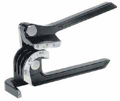
18 ACCESSORIES FUEL FUNNEL WITH FILTER STANDARD WRENCHES RATCHETS & SOCKETS TORSION BUSHING REAMER BEAD BREAKER INSTANT HEAT TIRE GROOVER ANGLE FINDER TAPE MEASURE REAR ARM TOOL HEATED TIRE SIPER SETUP BLOCKS CHAIN BREAK TOOL CHAIN LUBE HONEYCOMB RADIATOR PROTECTOR MOUNTING KIT ANTI SEIZE 425-D026ERL BRAKE FLUID LUG WRENCH EagleMotorsports.com

19 EagleMotorsports.com


20 NOW THAT YOU ARE COMPLETED ELECTRICAL PLUMBING SAFETY EagleMotorsports.com
55-64 Full Size GM (Impala, Bel Air, etc.) This kit is for axles with a 3 3/8 spread center to center on the top two bolt holes (pictured left).
 This kit is for axles with a 3 3/8 spread center to center on the top two bolt holes (pictured left).") SUM-BK1624A Full Size GM Installation Instructions Rear Disc Conversion 55-64 Full Size GM (Impala, Bel Air, etc.) This kit is for axles with a 3 3/8 spread center to center on the top two bolt holes (pictured
SUM-BK1624A Full Size GM Installation Instructions Rear Disc Conversion 55-64 Full Size GM (Impala, Bel Air, etc.) This kit is for axles with a 3 3/8 spread center to center on the top two bolt holes (pictured
Installing and Squaring the Rear Axle
 Installing and Squaring the Rear Axle 1. Level the GF1 frame; both front to back and left to right. 2. Install the Jacob s Ladder in the frame. 3. Insert your Torsion Bars and tighten the torsion arms,
A /F/X Body Instruction Packet Rear Disc Conversion
 A /F/X Body Instruction Packet Rear Disc Conversion 64-72 A Body / 67-81 F Body / 62-74 X Body This kit is for axles with a 3 1/8 spread center to center on the top two bolt holes (pictured left). Rotor
Revised BX-1000 BLACK MAX
 Revised 8-22-12 BX-1000 BLACK MAX PLEASE READ THROUGH THE ENTIRE MANUAL BEFORE INSTALLING YOUR BRAKE SYSTEM WARNING - DO NOT USE BRAKE FLUID - USE ATF HYDRAULIC FLUID ONLY **IMPORTANT** DO NOT USE ANY
Assembly Manual. For G17. Economy Kit
 Assembly Manual For G17 Economy Kit INTRODUCTION At NC Chassis we greatly appreciate your purchase of our Economy Kit. We are continuing our effort to provide the best product packages in Quarter Midget
RHINO SUSPENSION SYSTEM INSTALLATION INSTRUCTIONS
 PARTS INCLUDED: 2 FRONT UPPER A-ARMS 2 FRONT LOWER A-ARMS 2 UNI-BALL JOINTS 2 UNI-BALL JOINT STUDS 2 UNI-BALL JOINT CAPS 2 RETAINING RINGS 1 FRONT SHOCK ASSEM. 2 DELRON STEERING STOPS 2 SHOCK MOUNT SPACERS
INSTALLATION INSTRUCTIONS
 INSTALLATION INSTRUCTIONS FRONT DISC BRAKE CONVERSION KITS: A132-1, A133, A133-1 A134, A134-1 1968-73 MUSTANG/FORD Thank you for choosing STAINLESS STEEL BRAKES CORPORATION for your braking needs. Please
EGR Performance Brakes Assembly Instructions DODGE DANA 70 '87 - '93 (Will not fit stock sized dual rear wheels)
") EGR Performance Brakes Assembly Instructions DODGE DANA 70 '87 - '93 (Will not fit stock sized dual rear wheels) Got Brakes? Parts List (2) Vented Rotors (2) Multi hole Cable Mount & L Brkt (2) Axle Tube
EGR Performance Brakes Assembly Instructions DODGE DANA 70 '87 - '93 (Will not fit stock sized dual rear wheels) Got Brakes? Parts List (2) Vented Rotors (2) Multi hole Cable Mount & L Brkt (2) Axle Tube
POWER RACK AND PINION STEERING INSTALLATION
 by Randy Irwin 1955-57 POWER RACK AND PINION STEERING INSTALLATION Randy Irwin - Technical Writer Randy has been involved in the Chevy parts business for over 25 years. He is a wizard at creating, making
Circle Track Merchandising Display
 Part No: ALL070 Circle Track Includes 49 items selected for fast and frequent sales. Fits within a 4' x 4' area. Attractive packaging designs. Picture shown represents the recommended layout. Pegboard
Mopar 8 3/4 & 9 3/4 (Dana) Installation Instructions Rear Disc Conversion
 Installation Instructions Rear Disc Conversion") Mopar 8 3/4 & 9 3/4 (Dana) Installation Instructions Rear Disc Conversion This kit is for either Mopar 8 ¾ or Mopar 9 ¾ (Dana). This kit is designed to work with axles with either GM 5 x 4.75 Bolt Pattern
Mopar 8 3/4 & 9 3/4 (Dana) Installation Instructions Rear Disc Conversion This kit is for either Mopar 8 ¾ or Mopar 9 ¾ (Dana). This kit is designed to work with axles with either GM 5 x 4.75 Bolt Pattern
INSTALLATION INSTRUCTIONS
 INSTALLATION INSTRUCTIONS FX4 ELITE REAR DISC CONVERSION KITS WITH INTERNAL PARKING BRAKE A110-14, A111-25, A111-29 for FORD 8" & 9" REAR ENDS Thank you for choosing STAINLESS STEEL BRAKES CORPORATION
55-64 Full Size Chevy Installation Instructions Standard Disc Conversion
 55-64 Full Size Chevy Installation Instructions Standard Disc Conversion DBMC09, PV71 & PVB71 Pictured (Booster, master cylinder & valve setups may vary by upgrades selected) Your new disc brake conversion
INSTALLATION INSTRUCTIONS
 INSTALLATION INSTRUCTIONS PERFORMANCE AT THE WHEELS KITS W156-6 & W156-7 1965-74 MOPAR B & E BODY Thank you for choosing STAINLESS STEEL BRAKES CORPORATION for your braking needs. Pleases take the time
2005 to 2008 #08 Metric Nova Chassis Set Up Sheet
 Springs 1 2005 to 2008 #08 Metric Nova Chassis Set Up Sheet Flat end of spring down on tubular lower a-arms. Left Front 800lb. Right Front 750lb. Left Rear 200lb. Right Rear 225lb. On Top of Tube Axle
INSTALLATION INSTRUCTIONS
 INSTALLATION INSTRUCTIONS PERFORMANCE AT THE WHEELS KIT W155-5 CHRYSLER 8 3 /4" & 9 3 /4" REAR AXLES Thank you for choosing STAINLESS STEEL BRAKES CORPORATION for your braking needs. Please take the time
BX-1000 Hydraulic Brake System Azusa 8 inch Diameter Wheel
 BX-1000 Hydraulic Brake System Azusa 8 inch Diameter Wheel Installation Manual Made by Free Bird Innovations - 1380 Legion Road - Detroit Lakes - MN 56501 PLEASE READ THROUGH THE ENTIRE MANUAL BEFORE INSTALLING
INSTALLATION INSTRUCTIONS
 INSTALLATION INSTRUCTIONS FORCE 10 SPORT R1 REAR DISC CONVERSION KIT A126-50 2005-10 Chevrolet Silverado and GMC Sierra Thank you for choosing STAINLESS STEEL BRAKES CORPORATION for your braking needs.
60 76 A Body Mopar Power Disc Conversion Installation Instructions
 62-72 B & E BodyMopar 60 76 A Body Mopar Power Disc Conversion Installation Instructions Special A-Body only parts shown below (In addition to parts above for A-Body cars, part # MDC66DC & MDC46DC) Your
A/F/X Body GM Installation Instructions Manual Disc Conversion
 A/F/X Body GM Installation Instructions Manual Disc Conversion 64-72 A Body / 67-69 F Body / 62-74 X Body DBMC09 & PVK71 pictured above (Booster, master & valve setups may vary by upgrades selected) Your
Ford 8, 9 Small Bearing Installation Instructions Rear Disc Conversion
 Ford 8, 9 Small Bearing Installation Instructions Rear Disc Conversion This kit is for Ford 9 rear axles with the small (2.835 ) style bearing and Ford 8 rear ends. This kit is designed to work with axles
WARNING: the engine does not come with oil in it. Please fill the oil before starting. The 200cc hardknock requires 9/10 of a quart of oil.
 WARNING: the engine does not come with oil in it. Please fill the oil before starting. The 200cc hardknock requires 9/10 of a quart of oil. Things needed for assembly. -2 tubes of blue loc-tite. I don
DODGE OFF ROAD T-STYLE STEERING KIT INSTALLATION INSTRUCTIONS
 Dodge Off Road, LLC Specializing in Dodge Ram Solid-Axle 4x4 Suspension and Steering for Off Road Applications 855.9009.DOR sales@dodgeoffroad.com dodgeoffroad.com DODGE OFF ROAD T-STYLE STEERING KIT INSTALLATION
Our goal is to make the install a breeze. Please read the entire guide before beginning.
 www.airkewld.com Page 1 of 6 IRS Axle Kit Install IRS Axle Kit Install Our goal is to make the install a breeze. Please read the entire guide before beginning. KITS SHOULD INCLUDE 2 - Control-arm mounting
Full Size GM Installation Instructions
 Full Size GM Installation Instructions Rear Disc Conversion 55 64 Full Size GM (Impala, Bel Air, etc.) This kit is for axle with a 3 3/8 spread center to center on the top two bolt holes (pictured left).
Hoffman Auto Racing Use Parts Sale List (513)
") Hoffman Auto Racing Use Parts Sale List (513) 697-9537 10/28/2015 LIST PRICE SALE PRICE XYZ bird cages wing and non-wing pickups with dual row bearings (pr) XYZ angled broached RF torsion arm XYZ "S" bend
Hoffman Auto Racing Use Parts Sale List (513) 697-9537 10/28/2015 LIST PRICE SALE PRICE XYZ bird cages wing and non-wing pickups with dual row bearings (pr) XYZ angled broached RF torsion arm XYZ "S" bend
For all Ram x4 Trucks, and all Ram x4 trucks.
 Dodge Off Road, LLC Specializing in Dodge Ram Solid-Axle 4x4 Suspension and Steering for Off Road Applications 855.9009.DOR sales@dodgeoffroad.com dodgeoffroad.com DODGE OFF ROAD 5 th GEN STEERING KIT
INSTALLATION INSTRUCTIONS
 INSTALLATION INSTRUCTIONS BIG ROTOR / CALIPER RELOCATION REAR KIT SUM-BK1423 1999-2009 GM 1/2 Ton Trucks & SUVs Thank you for choosing SUMMIT RACING for your braking needs. Pleases take the time to read
INSTALLATION INSTRUCTIONS
 INSTALLATION INSTRUCTIONS FRONT DISC BRAKE CONVERSION KIT A129-2 1959-64 Full Size Chevrolet Car and FRONT DISC BRAKE CONVERSION KITS A129-3 & A129-4 1965-68 Full Size Chevrolet Car Thank you for choosing
INSTALLATION INSTRUCTIONS
 INSTALLATION INSTRUCTIONS REAR CONVERSION KIT A111-2 (FORD 8" & 9" SMALL BEARING) & REAR CONVERSION KIT A111-3 (FORD 9 TORINO) Thank you for choosing STAINLESS STEEL BRAKES CORPORATION for your braking
INSTALLATION INSTRUCTIONS
 INSTALLATION INSTRUCTIONS BIG ROTOR / CALIPER RELOCATION FRONT KITS SUM-BK1422, BK1423, BK1424 1999-2006 GM 1/2 Ton Trucks & SUVs Thank you for choosing SUMMIT RACING for your braking needs. Pleases take
Full Size GM Installation Instructions Rear Disc Conversion
 Full Size GM Installation Instructions Rear Disc Conversion 65 68 Full Size GM (Impala, Bel Air, etc.) This kit is for axles with a 3 3/8 spread center to center on the top two bolt holes (pictured left).
Slide the billet aluminum cap over the bushing and secure with the 3/8-16 x 2 1/2 socket head allen and locknuts provided.
 Slide the billet aluminum cap over the bushing and secure with the 3/8-16 x 2 1/2 socket head allen and locknuts provided. Put the urethane bushings into the upper antiroll-bar-link eyebolt. Coat the bushings
INSTALLATION INSTRUCTIONS
 INSTALLATION INSTRUCTIONS Disc Brake Spindle Kit SUM-BKA2447 1964-72 A-BODY 1967-69 F-BODY 1968-74 X-BODY Thank you for choosing SUMMIT RACING for your braking needs. Please take the time to read and carefully
INSTALLATION INSTRUCTIONS
 INSTALLATION INSTRUCTIONS PERFORMANCE AT THE WHEELS KIT W125-42 GM 10 & 12 Bolt Rear Axles with Staggered or non-staggered Shocks with C-Clips Thank you for choosing STAINLESS STEEL BRAKES CORPORATION
Assembly Manual. For G9. Economy Kit
 Assembly Manual For G9 Economy Kit INTRODUCTION At NC Chassis we greatly appreciate your purchase of our Economy Kit. We are continuing our effort to provide the best product packages in Quarter Midget
NEW BRAKE INSTALLATION. Let us show you how a
 Tech Article From Newsletter 17.2-2nd Quarter of 2011 NEW BRAKE INSTALLATION Let us show you how a Big Brake Install is easier than you think!! So, you have a 572 (or a hot 383) in your shoebox... you
INSTALLATION INSTRUCTIONS
 INSTALLATION INSTRUCTIONS FRONT DISC BRAKE CONVERSION KITS A148-9 & A148-15 1949-54 Chevy Trucks Thank you for choosing STAINLESS STEEL BRAKES CORPORATION for your braking needs. Please take the time to
Commander SUSPENSION SYSTEM INSTALLATION INSTRUCTIONS
 PARTS INCLUDED: 2 - FRONT UPPER A-ARMS 2 - FRONT LOWER A-ARMS 4 - COTTER PINS 2-12MM JAM NUTS 2 - TIE ROD EXTENDERS 8- FLANGED DELRON BUSHINGS 4- DELRON CASTER SPACERS 6 - GREASE FITTINGS 3 - BEARING REMOVAL
INSTALLATION INSTRUCTIONS
 INSTALLATION INSTRUCTIONS REAR DISC BRAKE CONVERSION KIT A125-2 1955-70 FULL SIZE CHEVROLET Thank you for choosing STAINLESS STEEL BRAKES CORPORATION for your braking needs. Pleases take the time to read
Sherco Setup and Lubrication Guide
 Sherco Setup and This guide is designed to provide the Sherco owner with instructions on how to: Set up a new bike Clean and re-oil the air filter Change the transmission oil Change the fork oil Repack
INSTALLATION INSTRUCTIONS
 INSTALLATION INSTRUCTIONS INSTALLATION INSTRUCTIONS FOR A136 REAR DRUM TO DISC BRAKE CONVERSION KIT for 1970-75 Jeep, CJ SERIES with Dana 44 flanged axle Thank you for choosing STAINLESS STEEL BRAKES CORPORATION
INSTALLATION INSTRUCTIONS
 INSTALLATION INSTRUCTIONS REAR DISC CONVERSION KIT A136-1 1976-86 AMC 20 AXLES WITH WARN FULL FLOATING AXLE CONVERSION Thank you for choosing STAINLESS STEEL BRAKES CORPORATION for your braking needs.
BRAKE SYSTEM Nissan 240SX DESCRIPTION BRAKE BLEEDING * PLEASE READ FIRST * BLEEDING PROCEDURES ADJUSTMENTS BRAKE PEDAL HEIGHT SPECS TABLE
 BRAKE SYSTEM 1990 Nissan 240SX 1990 BRAKE SYSTEMS Nissan Disc & Drum Axxess, Maxima, Pathfinder, Pickup, Pulsar NX, Sentra, Stanza, 240SX, 300ZX DESCRIPTION All brake systems are hydraulically operated
A /F/X Body Instruction Packet Rear Disc Conversion
 A /F/X Body Instruction Packet Rear Disc Conversion 64-72 A Body / 67-81 F Body / 62-74 X Body This kit is for axles with a 3 1/8 spread center to center on the top two bolt holes (pictured left). If your
INSTALLATION INSTRUCTIONS FOR THE MOTOR TRIKE CROSS COUNTRY / CROSS ROADS / HARD BALL RAKE KIT
 INSTALLATION INSTRUCTIONS FOR THE MOTOR TRIKE CROSS COUNTRY / CROSS ROADS / HARD BALL RAKE KIT Thank you for choosing the Motor Trike Cross Country / Cross Roads / Hard Ball rake kit. We ask that you read
R O A D S M I T H TRIKE CONVERSIONS BY THE TRIKE SHOP
 R O A D S M I T H TRIKE CONVERSIONS BY THE TRIKE SHOP Please thoroughly review the instructions before and during installation. Keep in mind that this product was designed to be installed by trained dealer
INSTALLATION INSTRUCTIONS
 INSTALLATION INSTRUCTIONS 2005-2012 Nissan Xterra/Frontier / Pathfinder PART NUMBERS: NP17500, NP17525, NP17550 FRONTIER PARTS & CORRESPONDING HARDWARE LIST XTERRA PATHFINDER ABOVE LISTED 1/2 Metal Lock
DISC BRAKE/DUAL MASTER CYLINDER CONVERSION. Tools, Equipment and Supplies Needed:
 Please take the time to read the enclosed instructions carefully. If you have any questions, call our Product Assistance personnel for clarification. It is important to note that these instructions contain
Signature Series A/F/X Body GM Installation Instructions Rear Disc Conversion
 Signature Series A/F/X Body GM Installation Instructions Rear Disc Conversion 64-72 A Body / 67-81 F Body / 62-74 X Body This kit is for axles with a 3 1/8 spread center to center on the top two bolt holes
A/F/X Body GM Installation Instructions Manual Disc Conversion
 A/F/X Body GM Installation Instructions Manual Disc Conversion 64-72 A Body / 67-69 F Body / 62-74 X Body DBMC09 & PVK71 pictured above (Booster, master & valve setups may vary by upgrades selected) Your
R O A D S M I T H TRIKE CONVERSIONS BY THE TRIKE SHOP
 R O A D S M I T H TRIKE CONVERSIONS BY THE TRIKE SHOP Please thoroughly review the instructions before and during installation. Keep in mind that this product was designed to be installed by trained dealer
(513) Hoffman Auto Racing Sale List (513)
 Hoffman Auto Racing Sale List (513)") (513) 697-9537 Hoffman Auto Racing Sale List (513) 697-9537 11/22/2011 LIST PRICE SALE PRICE MPD Aluminum U-Joint assembly $ 75.00 U-Joint #6875 New style Thicker Yoke 27 races since new U-Joint #6998
(513) 697-9537 Hoffman Auto Racing Sale List (513) 697-9537 11/22/2011 LIST PRICE SALE PRICE MPD Aluminum U-Joint assembly $ 75.00 U-Joint #6875 New style Thicker Yoke 27 races since new U-Joint #6998
A /F/X Body Instruction Packet Rear Disc Conversion
 A /F/X Body Instruction Packet Rear Disc Conversion 64-72 A Body / 67-81 F Body / 62-74 X Body This kit is for axles with a 3 1/8 spread center to center on the top two bolt holes (pictured left). If your
TOYOTA TUNDRA BIG BRAKE KIT Section I - Installation Preparation
 TOYOTA TUNDRA 2007- BIG BRAKE KIT Section I - Installation Preparation Part Number: PTR09-34070 Kit Contents Item # Quantity Reqd. Description 1 1 Brake Rotor, LH Front 2 1 Brake Rotor, RH Front 3 1 Brake
IRS-151 INSTALLATION INSTRUCTIONS `55-57 CHEVY INDEPENDENT REAR SUSPENSION
 IRS-151 INSTALLATION INSTRUCTIONS `55-57 CHEVY INDEPENDENT REAR SUSPENSION Please read these instructions completely before starting your installation. Remember the basic rule for a successful installation:
INSTALLATION INSTRUCTIONS
 INSTALLATION INSTRUCTIONS REAR DISC BRAKE CONVERSION KIT A158 1994-97 Dodge Ram 1500 (2WD & 4WD) and REAR DISC BRAKE CONVERSION KIT A158-1 1998-01 Dodge Ram 1500 (2WD & 4WD) Thank you for choosing STAINLESS
LEXUS IS 250 Front Performance Brake Kit Section I - Installation Preparation
 LEXUS IS 250 Front 2006- Performance Brake Kit Section I - Installation Preparation Part Number: PTR09-53080 Kit Contents Item # Quantity Reqd. Description 1 1 Brake Rotor, LH Front 2 1 Brake Rotor, RH
2003 Jaguar X-Type BRAKES' 'Disc - X-Type
 REAR DISC BRAKE CALIPER WARNING: Brake dust, if inhaled can damage your health. Always remove brake dust using a vacuum brush. Do not use a compressed air line to disperse brake dust into the atmosphere.
Installation Instructions
 Preparing your vehicle to install your brake system upgrade 1. Rack the vehicle. 2. If you don t have a rack, then you must take extra safety precautions. 3. Choose a firmly packed and level ground to
INSTALLATION INSTRUCTIONS
 INSTALLATION INSTRUCTIONS FRONT BIG BRAKE CONVERSION KIT A112-5 1987-93 FORD MUSTANG Thank you for choosing STAINLESS STEEL BRAKES CORPORATION for your braking needs. Pleases take the time to read and
INSTALLATION INSTRUCTIONS
 INSTALLATION INSTRUCTIONS POWER FRONT DISC CONVERSION KIT A126-7 1963-66 CHEVY C10 PICKUP NON-POWER FRONT DISC CONVERSION KIT A126-8 1963-72 CHEVY C10 PICKUP Thank you for choosing STAINLESS STEEL BRAKES
Installation Notes: #86000-R Race Series +3.5 L/T Kit
 159 North Maple St. Unit J, CORONA CA 92880 P. 951-737-9682 F. 951-737-9006 WWW.CHAOSFAB.COM Installation Notes: #86000-R Race Series +3.5 L/T Kit Factory manual is recommended for removal and re-installation
INSTALLATION INSTRUCTIONS
 INSTALLATION INSTRUCTIONS REAR DISC BRAKE CONVERSION KIT A125-3 1965-72 GM A-BODY 10 & 12 BOLT AXLES Thank you for choosing STAINLESS STEEL BRAKES CORPORATION for your braking needs. Pleases take the time
GM FULL SIZE REAR DISC BRAKE KIT
 GM FULL SIZE REAR DISC BRAKE KIT This kit is for axles with a 3 3/8 spread center to center on the top two bolt holes (pictured left). If your axle flange measures 3 1/8 from center to center, you need
M-2300-M Mustang GT Rear Disc Brake Bracket Kit INSTALLATION INSTRUCTIONS
 Please contact the Tech Line for the most current instruction information (800) 367-3788!!! PLEASE READ THE FOLLOWING INSTRUCTIONS CAREFULLY PRIOR TO INSTALLATION!!! INTRODUCTION: This kit allows for the
INSTALLATION INSTRUCTIONS
 INSTALLATION INSTRUCTIONS R1 REAR DRUM TO DISC BRAKE CONVERSION KIT A130-3 JEEP CJ SERIES W/AMC-20 REAR AXLES AND 5 x 5-1/2" BOLT CIRCLE Thank you for choosing STAINLESS STEEL BRAKES CORPORATION for your
INSTALLATION INSTRUCTION 88581
 INSTALLATION INSTRUCTION 88581 FOR RANCHO SUSPENSION SYSTEM RS6581B: DODGE RAM READ ALL INSTRUCTIONS THOROUGHLY FROM START TO FINISH BEFORE BEGINNING INSTALLATION Rev C IMPORTANT NOTES! WARNING: This suspension
INSTALLATION INSTRUCTION Rev A
 INSTALLATION INSTRUCTION 88587 Rev A FOR RANCHO SUSPENSION SYSTEM RS6587B: 2009 DODGE RAM 1500 READ ALL INSTRUCTIONS THOROUGHLY FROM START TO FINISH BEFORE BEGINNING INSTALLATION IMPORTANT NOTES! WARNING:
BIG BRAKE KIT FOR TJ, ZJ, XJ D44 & D30
 BIG BRAKE KIT FOR TJ, ZJ, XJ D44 & D30 16 KIT PART NUMBER 41002010AA 17 KIT PART NUMBER 41002015AA Installation Guide (Updated 12/01/09) Page 1 of 11 PLEASE READ BEFORE YOU START IN ORDER TO INSTALL THIS
Parking brake Mechanical brake acting on rear wheels
 11 Brake System 11.1 General SPECIFICATIONS EJTC0010 Master cylinder Type Tandem type I.D. mm(in.) 20.64 mm (0.813 in.) Fluid level warning sensor Provided Brake booster Type Vacuum Boosting ratio 4.0
Next, set the bar level and tighten it down. Do this on both the driver and passenger sides.
 Next, set the bar level and tighten it down. Do this on both the driver and passenger sides. Using two tape measures, measure the outside width at the front and the rear of the tubes. The front dimension
INSTALLATION INSTRUCTIONS PERFORMANCE AT THE WHEELS KIT W125
 INSTALLATION INSTRUCTIONS PERFORMANCE AT THE WHEELS KIT W125 1968-81 CAMARO & FIREBIRD 10 & 12 BOLT W/"C" CLIPS Thank you for choosing STAINLESS STEEL BRAKES CORPORATION for your braking needs. Pleases
Installation Instructions
 Installation Instructions Rear Disc Brake Conversion Kit Item # RC1001, RC1001X Applications: 64-72 A-body, 67 F-Body, 63-67 X-body with Non Staggered Shocks Thank you for choosing GPS Auto for your automotive
Brake System Diagnosis and Service
 AUMT 1310 - Brake System Diagnosis and Brake System Inspection Brake System Diagnosis and Donald Jones Brookhaven College Road test Hydraulic system Leaks Fluid condition Disc brakes Rotors and pads Drum
1 Bordnersville Rd. Jonestown, Pa Phone Fax On The Web at
 Serial #2023 and up Updated 12/14/17 Manufactured By: 1 Bordnersville Rd. Jonestown, Pa 17038 Phone 717-865-3119 Fax 717-865-0904 E-mail lazerchassis@comcast.net On The Web at www.lazerchassis.com Dear
BRAKE SYSTEM Toyota Celica DESCRIPTION DRUM BRAKES ADJUSTMENTS BRAKE PEDAL HEIGHT ADJUSTMENTS BRAKE PEDAL FREE PLAY ADJUSTMENTS
 BRAKE SYSTEM 1988 Toyota Celica 1988-89 BRAKES Toyota Celica, Corolla, MR2, Tercel DESCRIPTION The hydraulic brake system uses a tandem master cylinder with a vacuum power assist servo. MR2 and some Celica
INSTALLATION INSTRUCTIONS
 INSTALLATION INSTRUCTIONS FRONT DISC BRAKE CONVERSION KITS SUM-BK1200, SUM-BK1201, SUM-BK1202, SUM-BK1203 1964-72 A-BODY 1967-69 F-BODY 1962-74 X-BODY (NOTE: 62-64 X-BODY REQUIRES 5-LUG STEERING ARMS)
INSTALLATION INSTRUCTIONS
 INSTALLATION INSTRUCTIONS REAR DISC BRAKE CONVERSION KITS SUM-BK1329-X, SUM-BK1329-99904, SUM-BK1330-X, SUM-BK1330-99904 CHRYSLER 8 3 /4", 9 3 /4" and 2-PIECE REAR AXLES Thank you for choosing SUMMIT RACING
M-2300-T 6-Piston Mustang Brake Kit INSTALLATION INSTRUCTIONS
 Please visit www.fordracingparts.com for the most current instruction information!!! PLEASE READ ALL OF THE FOLLOWING INSTRUCTIONS CAREFULLY PRIOR TO INSTALLATION. AT ANY TIME YOU DO NOT UNDERSTAND THE
Parts Manual PZ Please read the operator manual carefully and make sure you understand the instructions before using the machine.
 Parts Manual PZ 60 967 045601-00 Please read the operator manual carefully and make sure you understand the instructions before using the machine. When you need spare parts or support in service questions,
INSTALLATION INSTRUCTIONS
 INSTALLATION INSTRUCTIONS REAR DISC BRAKE CONVERSION KITS A112, A112-1 & A112-93 1979-93 FORD MUSTANG with 7.5" & 8.8" AXLES Thank you for choosing STAINLESS STEEL BRAKES CORPORATION for your braking needs.
INSTALLATION INSTRUCTIONS 97 FORD EXPEDITION
 INSTALLATION INSTRUCTIONS 97 FORD EXPEDITION 1. Read the instructions completely and carefully before you begin. Check the kit for proper contents (refer to the part s list and the picture diagrams). Before
INSTALLATION INSTRUCTIONS
 INSTALLATION INSTRUCTIONS REAR DISC BRAKE CONVERSION KIT A126-1 1973-87 CHEVROLET 1/2 TON 2WD Thank you for choosing STAINLESS STEEL BRAKES CORPORATION for your braking needs. Pleases take the time to
INSTALLATION INSTRUCTION 89400
 INSTALLATION INSTRUCTION 89400 FOR RANCHO SUSPENSION SYSTEM RS66400B: 2012 RAM 1500 4WD. READ ALL INSTRUCTIONS THOROUGHLY FROM START TO FINISH BEFORE BEGINNING INSTALLATION Rev B IMPORTANT NOTES! WARNING:
OVER THE KNUCKLE 1-TON STEERING INSTALLATION INSTRUCTIONS
 OVER THE KNUCKLE 1-TON STEERING INSTALLATION INSTRUCTIONS TOOLS NEEDED Grinder with cutoff wheel, sawzall, cutting torches, or a plasma cutter Welder (for optional sway bar mounts) Hand drill with a ½
55-64 Full Size Chevy
 55-64 Full Size Chevy Installation Instructions Power Disc Conversion 9 slimline booster pictured Your new disc brake conversion kit can be bolted up with standard hand tools. The only tools you may not
First, check and record the camber and caster readings, they will be adjusted later.
 First, check and record the camber and caster readings, they will be adjusted later. The caliper-mounting bosses are machined perpendicular to the spindle so they are an excellent place for the level.
Chevy Nova Pro-Touring Front Suspension Installation Instructions
 1962-1967 Chevy Nova Pro-Touring Front Suspension Installation Instructions 1-800-984-6259 www.totalcostinvolved.com 1 Pro-Touring Clip A-Arm Assembly Sway Bar Assembly Fender Panel Kit 8 7/16-20 * 1 ¼
R O A D S M I T H TRIKE CONVERSIONS BY THE TRIKE SHOP
 R O A D S M I T H TRIKE CONVERSIONS BY THE TRIKE SHOP Please thoroughly review the instructions before and during installation. Keep in mind that this product was designed to be installed by trained dealer
Hoffman Auto Racing Sale List
 Hoffman Auto Racing Sale List 0/9/0 NEW Winters 4.: w/5: light black axle and Black Thermal coating Winters 4.: Medium weight axle Weld Direct Mount Hubs Ultra light w/ bearings pair Titanium spindles
70001 and Clutch Rebuild Instructions
 70001 and 70010 Clutch Rebuild Instructions Brinn, Incorporated 1615 Tech Drive Bay City, MI 48706 Telephone 989.686.8920 Fax 989.686.6520 www.brinninc.com Notice Use these instructions if you only want
INSTALLATION INSTRUCTIONS
 INSTALLATION INSTRUCTIONS REAR CONVERSION KITS SUM-BK1326-X, SUM-BK1326-99904, SUM-BK1327-X, SUM-BK1327-99904, SUM-BK1328-X, SUM-BK1328-99904 FORD 8 and 9 AXLES WITH GM & FORD BOLT PATTERN Thank you for
To Order Call (562)
") 451 Park Industrial Dr. La Habra CA 90631 Phone: (562) 691-7006 Fax: (562) 691-5708 www.kugelkomponents.com 2017 PRICE SHEET #17 INDEPENDENT FRONT SUSPENSION SYSTEMS For All IFS Powder Coated (Black Only):
451 Park Industrial Dr. La Habra CA 90631 Phone: (562) 691-7006 Fax: (562) 691-5708 www.kugelkomponents.com 2017 PRICE SHEET #17 INDEPENDENT FRONT SUSPENSION SYSTEMS For All IFS Powder Coated (Black Only):
»Product» Safety Warning
 Read and understand all instructions and warnings prior to installation of product and operation of vehicle. RBP recommends this system be installed by a professional technician. In addition to these instructions,
73-87 Chevy C-10 Rack and Pinion Conversion Kit
 73-87 Chevy C-10 Rack and Pinion Conversion Kit For safety, disconnect battery cables and ensure that vehicle is properly supported by jack stands. NOTE: Power Steering Line Kit (FR1610) is sold separately
INSTALLATION INSTRUCTIONS
 INSTALLATION INSTRUCTIONS REAR DISC BRAKE CONVERSION KIT A157 1991-2004 Dodge Dakota 2WD 1991-2002 Dodge Dakota 4WD 1998-2002 Dodge Durango Thank you for choosing STAINLESS STEEL BRAKES CORPORATION for
# " Suspension System Jeep Wrangler TJ. 102 S. Michigan Avenue Coldwater, MI
 #014452 4.5" Suspension System Jeep Wrangler TJ Read and understand all instructions and warnings prior to installation of system and operation of vehicle. SAFETY WARNING BDS Suspension Co. recommends
Parts Manual Zero Turn Mower / Z 254i
 Parts Manual Zero Turn Mower / Z 254i 967324201-00 Please read the operator manual carefully and make sure you understand the instructions before using the machine. When you need spare parts or support
Caution: Refer to Adding Fluid to the Brake System Caution in the Preface section.
 Page 1 of 6 2009 Pontiac G8 G8 Service Manual Brakes Disc Brakes Repair Instructions Document ID: 2094891 Rear Disc Brake Pads Replacement Special Tools J 23738-A Hand Vacuum Pump. Removal Procedure Warning: