TECHNICAL MANUAL DIRECT SUPPORT AND GENERAL SUPPORT MAINTENANCE MANUAL (INCLUDING REPAIR PARTS AND SPECIAL TOOLS LIST) STARTER, ENGINE, ELECTRICAL
|
|
|
- Brianna Joseph
- 5 years ago
- Views:
Transcription
1 TM TECHNICAL MANUAL DIRECT SUPPORT AND GENERAL SUPPORT MAINTENANCE MANUAL (INCLUDING REPAIR PARTS AND SPECIAL TOOLS LIST) STARTER, ENGINE, ELECTRICAL LEECE-NEVILLE MODEL M MB ( ) HEADQUARTERS, DEPARTMENT OF THE SSARMY MAY 1975
2
3 C1 CHANGE NO. 1 HEADQUARTERS DEPARTMENT OF THE ARMY Washington, D.C., 19 September 1994 DIRECT SUPPORT AND GENERAL SUPPORT MAINTENANCE MANUAL (INCLUDING REPAIR PARTS AND SPECIAL TOOLS LIST) FOR STARTER, ENGINE, ELECTRICAL LEECE-NEVILLE MODEL M MB ( ) TM , dated 15 May 1975, is changed as follows: 1. Remove old pages and insert new pages. 2. New or changed material is indicated by a vertical bar in the margin of the page. Remove pages Insert pages 3-19 and and 3-20 Index-1 /(Index-2 blank) Index-1 /(Index-2 blank) 3. File this change sheet in front of the publication for reference purposes. By Order of the Secretary of the Army: Official: GORDON R. SULLIVAN General, United States Army Chief of Staff MILTON H. HAMILTON Administrative Assistant to the Secretary of the Army Distribution: To be distributed in accordance with DA Form E, (Block 0536) for TM Approved for public release: distribution is unlimited.
4
5 T ECHNICAL M ANUAL No HEADQUARTERS DEPARTMENT OF THE ARMY WASHINGTON, DC, 15 May 1975 DIRECT SUPPORT AND GENERAL SUPPORT (INCLUDING REPAIR MAINTENANCE MANUAL PARTS AND SPECIAL TOOLS LIST) STARTER, ENGINE, ELECTRICAL LEECE-NEVILLE MODEL M MB ( ) Current as of 4 December 1974 Paragraph Page CHAPTER Section 1. I. II. INTRODUCTION General Description and data CHAPTER Section 2. I. II. DIRECT SUPPORT AND GENERAL SUPPORT MAINTENANCE Repair parts, special tools and equipment Troubleshooting INSTRUCTIONS CHAPTER Section 3. I. II. III. IV. v. REPAIR INSTRUCTIONS General Disassembly Assembly Tests and adjustments Repair and rebuild standards APPENDIX A. REFERENCES A-1 B. I. II. III. IV. REPAIR PARTS AND SPECIAL TOOLS LIST Introduction Repair parts list Special tools list National/NATO stock number and part number index B-1 B-1 B-4 B-7 B-11 INDEX Index-1 *This manual supersedes TM , 21 March i
6 Number LIST OF ILLUSTRATIONS Title P a g e B-1 B-3 Electrical engine starter assembly Engine, electrical starter assembly-sectional view Improvised brush spring lifter Removing or installing jumper and lead assembly Removing or installing relay adjusting shaft access plug Removing or installing relay assembly attaching parts Disconnecting or connecting relay adjusting shaft using shaft adjusting tool Removing or installing pinion housing assembly attaching parts Removing or installing pinion housing and related parts Removing or installing pinion housing oil wick Removing or installing lever shaft retaining screw and washer Removing or installing lever shaft Removing or installing shaft housing assembly attaching parts Removing or installing drive and shaft and lever assemblies Removing or installing drive clutch thrust washers Disassembling or assembling shaft and lever assembly Removing or installing shift housing packages and oil wick Removing or installing armature Removing or installing armature thrust washers Removing or installing brush opening band Disconnecting or connecting brushes Removing or installing brushes in brush rigging using improvised spring lifter Removing or installing brush rigging assembly attaching parts Removing or installing brush rigging Removing or installing brush spring holders Removing or installing brush rigging jumper screw and attaching parts Disassembling or assembling commutator end housing assembly Testing field coils for grounds Testing armature for grounds Testing armature for short circuits Checking armature eccentricity Removing or installing bearing in pinion housing Removing or installing bearing in shift position Removing or installing bearing in commutator end housing Cutting tool sharpening dimensions Proper position of cutting tool Polishing armature commutator with sandpaper Positioning jumper or brush riggin assembly Positioning sandpaper or armature Rotating armature to seat brushes Examples of satisfactory and unsatisfactory brush seats Measuring armature end play Pinion housing position for LDS-465-l, LDS-465-lA and MACK Model ENDT 673 engine application Pinion housing position for LD-465-l, LD465-lC and LDT-465-lC engine application Pinion housing position for LDS engine application Measuring drive clutch pinion clearance Starter test setup Electrical engine starter assembly Starter assembly -exploded view Special tool B-4 B-5 B-6 ii
7 CHAPTER 1 INTRODUCTION Section I. GENERAL 1-1. Scope This manual is for your use Electrical Engine Starter Neville Model M MB (fig. 1-1). in maintaining the Assembly, Leece- ( ) 1-2. Maintenance Forms and Records Maintenance forms and records that you are required to use are explained in TM Reporting of Errors You can improve this manual by calling attention to errors and by recommending improvements using DA Form 2028 (Recommended Changes to Publications and Blank Forms) or by a letter and mail direct to Commander, US Army Tank- Automotive Command, ATTN: AMSTA-MSP, Warren, MI A reply will be furnished direct to you. Section Il. DESCRIPTION AND DATA 1-4. Description This electrical starter is a heavy duty, 24-volt, insulated, waterproof, fungus and corrosion resistant, solenoid operated, enclosed shift -lever type with eight brushes retained in four brush holders. The drive assembly is a heavy duty, overrunning type and the pinion clearance is adjustable. The starter assembly consists of eight major components, These are the brush rigging assembly, shift housing assembly, shaft and lever assembly, pinion housing assembly, drive assembly, armature assembly, and field ring assembly Tabulated Data Voltage vdc Current at rated load (rated max) amps Horsepower (rated) 8.5 hp at 2550 rpm Stall torque lbs-ft Pinion rotation (facing drive end) clockwise Number of pinion teeth (one tooth blank) Mounting data: Number of mounting holes Diameter of mounting holes in. Mounting holes circle diameter in. Length in. Height in. Diameter (field ring) in. Weight lbs 1-1

8 Figure 1-1. Electrical engine starter assembly. 1-2

9 A - Fiber thrust washer B - Steel thrust washer C - Preformed packing D - Brush E - Solenoid relay assembly F - Preformed packing G - Switch shaft seal H - Field coils J - Steel thrust washer K - Fiber thrust washer L - Shift housing bushing-type bearing M - Fiber washer N - Shift housing P - Shaft and lever assembly Q - Preformed packing R - Pinion housing S - Oil wick T - Pinion housing bushing-type bearing U - Drive assembly V - Armature oil seal W - Field ring X - Armature Y - Brush opening band Z - Commutator end housing AA - Brush holder and spring assembly BB - Commutator end housing bushing-type bearing Figure 1-2. Engine electrical starter assembly - sectional view. 1-3
10
11 CHAPTER 2 DIRECT SUPPORT AND GENERAL SUPPORT MAINTENANCE INSTRUCTIONS Section I. REPAIR PARTS, SPECIAL TOOLS AND EQUIPMENT 2-1. Tools and Equipment Standard and commonly used tools and equipment having general application to this materiel are authorized for issue by Tables of Allowance (TA) and Tables of Organization and Equipment (TOE) Special Tools and Equipment Special tools and equipment required to perform repair and rebuild operations contained in this manual are listed in appendix B Repair Parts Repair parts for the starter assembly are listed in appendix B which is the authority for requisitioning replacements Improvised Tools The dimensional detail drawing of the improvised brush spring lifter (fig. 2-1) applies only to direct and general support shops to enable these maintenance organizations to fabricate the tools locally, if desired. This tool is of chief value to maintenance organizations engaged in rebuilding a large number of identical components; however, it is not essential for rebuild and is not available for issue. Figure 2-1. Improvised brush spring lifter. Section Il. TROUBLESHOOTING 2-5. General a. This section contains troubleshooting information for locating and correcting most of the operating troubles which may develop in the starter. Each malfunction for an individual component is followed by a list of tests or inspections which will help you to determine probable causes and corrective actions to take. You should perform the tests/inspections and corrective actions in the order listed. b. This manual cannot list all malfunctions that may occur, nor all tests or inspections and corrective actions. If a malfunction is not listed or is not corrected by listed corrective actions, notify your supervisor. c. Troubleshooting a disabled starter after it has been removed from the vehicle and/or engine consists of subjecting it to tests on a suitable test stand. Information pertaining to this testing is contained in paragraphs 3-26 through Procedures After the starter has been received by the maintenance activity for preliminary inspection, or if performance of the starter has been unsatisfactory due to unknown causes, it must be inspected as described in this section. When the cause for failure has been found, the starter should be disassembled and repaired before proceeding with the tests. Additional operational tests performed on a damaged starter would only increase the damage. The following chart lists the common malfunctions that might be encountered, their probable causes, and the recommended corrective action. NOTE Make certain that unusual noises are not produced by the test equipment used. 2-1
12 Table 2-1. Troubleshooting Malfunction Test or Inspection Corrective Action STARTER 1. Starter Fails to Crank. Step 1. Check to see if starter is frozen. Disassemble starter (para 3-4 through 3-12) and check for cause (para 3-14). Step 2. Check to see if current is reaching starter by connecting a voltmeter between starter terminal and ground. Energise starter and observe voltmeter. A reading of approximately 24 volts should be indicated. If no reading is noted, trace out starter circuit and check battery condition. (Refer to pertinent operator/organizational manual). Step 3. Check to see if solenoid relay is defective by placing a jumper across battery terminal and relay terminal. If relay does not operate, remove relay (para 3-5) and install new relay (para 3-25). Step 4. Remove brush opening band (para 3-11a ), and check for poor brush spring tension and worn brushes (para 3-14e ). This condition is usually indicated by a slight voltage drop at starter terminal. If brushes are worn or spring tension is poor, replace brushes and/or springs as necessary and install band (para 3-20). Step 5. Check for worn or pitted commutator. This condition may show a slight voltage drop when the starter is energized depending upon the extent of the damage. Disassemble starter (para 3-4 through 3-12), resurface commutator (para 3-15e ), and assemble starter (para 3-16 through 3-25). 2. Low Speed and Low Current. Step 1. Check for high internal resistance. Remove brush opening band (para 3-11a ) and tighten brush leads. Install band (para 3-20f ). Step 2. Check for poor brush contact by removing brush opening band (para 3-1 la ) and inspecting commutator (para 3-14g ) for worn or dirty condition. If commutator is worn or dirty, disassemble starter (para 3-4 through 3-12), resurface commutator (para 3-15e ), and assemble starter (para 3-16 through 3-25). Check for worn brushes (para 3-14e ). 3. Low Speed and High Current. Step 1. Check to see if the armature is faulty due to excessive brush arcing. If brush arcing is apparent, disassemble starter (para 3-4 through 3-12), check armature for grounds or shorts (para 3-14g ). Replace starter if armature is grounded. Step 2. Check for armature drag by disassembling starter (para 3-3 through 3-12), inspect bearings and armature (para 3-14b c, g and h). Repair armature (para 3-15e ), and/or replace bearings as necessary, and assemble starter (para 3-16 through 3-25). 4. Starter Produces Excessive Noise. Step 1. Inspect bearings for lack of lubrication. Lubricate bearings (para 3-17). Step 2. Check for worn bearings by disassembling starter (para 3-4 through 3-12), and inspecting the bearings (para 3-14b, c, and h ). Replace bearings, if necessary, and assemble starter (para 3-16 through 3-25). Step 3. Inspect for loose pole shoes. Tighten pole shoe screws. 5. Starter Fails to Crank or Operates Very Slowly. Step 1. Check to see if armature shows excessive brush arcing, disassemble starter (para 3-4 through 3-12), check armature for grounds or shorts (para 3-14g ). Replace starter if armature is grounded. Step 2. Check for worn, binding, or poorly seated brushes by removing brush opening band (para 3-1 la ), and checking brush spring tension (para 3-14e ) and brush condition. Replace springs and/or brushes as necessary and install band (para 3-20f ). Step 3. Check for poor commutation due to dirty, rough, or pitted commutator. Disassemble starter (para 3-4 through 3-12, resurface commutator (para 3-15e ), and assemble starter (pars 3-16 through 3-25). Step 4. Check for eccentric commutator (out of round) by disassembling starter (para 3-4 through 3-12) and checking eccentricity (para 3-14g ). Step 5. Inspect field coils to see if they are grounded (para 3-14f ). If field coils are grounded, replace starter. 6. Excessive Arcing of Brushes. Step 1. Remove brush opening band (para 3-1 la ) and check for worn, binding or broken brushes or defective springs (para 3-14e ). Replace brushes and/or springs as necessary and install band (para 3-20f ). Step 2. Check for scored, pitted or dirty commutator. Disassemble starter (para 3-4 through 3-12), resurface commutator (para 3-15e ), and assemble starter (para 3-16 through 3-25). 2-2
13 Table 2-1. Troubleshooting-Continued Malfunction Test or Inspection Corrective Action STARTER-Continued Step 3. Check for eccentric commutator (out of round) by disassembling starter (para 3-4 through 3-12) and checking eccentricity (para 3-14g). Repair commutator (para 3-15e), if possible, and assemble starter (para 3-16 through 3-25). Step 4. Inspect field coils for shorts or grounds (para 3-14f). If field coils are grounded, replace starter. Step 5. If armature shows excessive brush arcing, disassemble starter (para 3-4 through 3-12) check armature for grounds or shorts (para 3-14g). Replace starter if armature is grounded. 7. Starter Drive Fails to Engage. Step 1. Check operation of solenoid relay by placing a jumper across battery terminal and solenoid relay terminal. This should cause the relay to operate. If the relay does not operate, remove relay (para 3-5) and install new relay (para 3-25). Step 2. Check to see if solenoid relay linkage is adjusted properly (para 3-25f). If adjustment is incorrect, remove solenoid relay adjusting plug and adjust linkage (para 3-25f). Step 3. Check for binding in shift lever or drive assembly by partially disassembling starter (para 3-5, 3-6 and 3-7). Inspect lever (para 3-14i) and drive assembly (para 3-14d) for defective parts. Replace defective parts and assemble starter (para 3-23, 3-24 and 3-25). 8. Starter Vibrates During Operation. Check for worn or damaged bearings by disassembling starter (para 3-4 through 3-12), inspect bearings (para 3-14b, c, and h). Replace bearings if necessary and assemble starter (para 3-16 through 3-25). 9. Drive Assembly Pinion Will Not Override. Check for defective drive by disassembling starter (para 3-4 through 3-12) and inspecting drive assembly. Replace drive assembly, if necessary, and assemble starter (para 3-16 through 3-25). 2-3
14

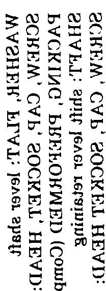
15 CHAPTER 3 REPAIR INSTRUCTIONS Section I. GENERAL 3-1. Removal and Installation Before beginning disassembly, wash starter For instructions covering removal and in- exterior thoroughly with drycleaning solvent stallation of the starter, refer to TM Type II (SD-2), Federal Specification P-D for LDS-465-1, and LDS-465-1A and MACK and dry with compressed air (15 psi). Model ENDT 673 engines, TM for 3-3. Parts Kit LD-465-1, LD-465-1C and LDT-465-1C engines, Standard parts kits should always be used when and TM for the LDS engine. repairing or rebuilding starter assembly. Refer to 3-2. Cleaning Before Disassembly Appendix B for description of parts kits. Section Il. DISASSEMBLY 3-4. General a. Disassembly of starter will be performed as illustrated in the following figures and instructions. Sequence of disassembly steps are shown in alphabetical order on each illustration. b. All packings and gaskets will be discarded during disassembly and new parts installed during assembly Removal of Solenoid Relay a. Remove in following sequence: two hex nuts (A, fig. 3-1) and jumper (B); two hex nuts (C) and lockwashers (D); hex nut (E); and lead assembly (F). b. Remove adjusting shaft access plug (fig. 3-2). c. Remove two hex-head bolts (A, fig. 3-3) securing relay assembly (B) to field ring assembly. d. Insert shaft adjusting tool (A, fig. 3-4) through access opening in relay cover. Engage end of tool with adjusting shaft and turn tool counterclockwise (B) until relay is free of plunger. Remove relay assembly (C). Figure 3-1. Removing or installing jumper and lead assembly. 3-1
 from armature shaft. Figure 3-4.")

 Scribe alinement marks (A, fig.")
.")
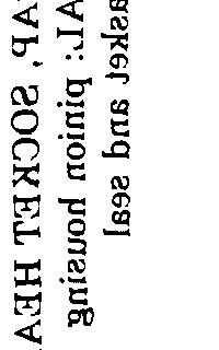
16 (2) Remove pinion housing (A, fig. 3-6), from starter and then remove and discard packing (B). Remove thrust washer (C) from armature shaft. Figure 3-4. Disconnecting or connecting relay adjusting shaft using shaft adjusting tool. Figure 3-2. Removing or installing relay adjusting shaft access plug. Figure 3-3. Removing or installing relay assembly attaching parts Removal and Disassembly of Pinion Housing Assembly a. Removal. (1) Scribe alinement marks (A, fig. 3-5) on shift housing and pinion housing (C) for proper positioning of pinion housing during assembly. Remove six hex-socket head screws (B). Tap around edges of pinion housing (C) to loosen housing pilot from its bore in shaft housing. Figure 3-5. Removing or installing pinion housing assembly attaching parts. 3-2
 and oil wick (B) from pinion housing. Remove six seal plugs (C) from housing.")
 and flat washer (B). b. Thread hex-socket head screw (A, fig.")
 on shaft housing assembly (D) and field ring. Remove six hex-socket head screws (B) and Slide shift housing assembly position shown in figure 3-11.")
17 Figure 3-6. Removing or installing pinion housing and related parts. b. Disassembly. Remove hex-socket head plug (A, fig. 3-7) and oil wick (B) from pinion housing. Remove six seal plugs (C) from housing. Do not attempt to remove bushing-type bearing since it should not be replaced unless it fails to meet inspection requirements (para 3-14b) Removal of Shift Housing Assembly a. Remove hex-socket head screw (A, fig. 3-8) and flat washer (B). b. Thread hex-socket head screw (A, fig. 3-9) into lever shaft (B) and pull shaft from shift housing. Remove screw and packing (C) from shaft. c. Scribe an alinement (A, fig. 3-10) on shaft housing assembly (D) and field ring. Remove six hex-socket head screws (B) and Slide shift housing assembly position shown in figure lockwashers (C). (D) forward to Figure 3-7. Removing or installing pinion housing oil wick. Figure 3-8. Removing or installing lever shaft retaining screw and washer. 3-3
, shift housing assembly (B), fiber washer (C), and steel thrust washer (D) from armature shaft.")


18 e. Remove two fiber thrust washers (A, fig. 3-12), shift housing assembly (B), fiber washer (C), and steel thrust washer (D) from armature shaft. Figure Removing or installing drive and lever assemblies. Figure 3-9. Removing or installing lever shaft. Figure Removing or installing drive clutch thrust washers. Figure Removing or installing shaft housing assembly attaching parts. d. Slide drive assembly (A, fig. 3-11) out of shift housing assembly and guide shaft and lever assembly (B) down and out of housing at the same time Shaft and Lever Assembly (Fig. 3-13) Press out roll pins (A and C) to separate shaft and insert assembly (B) and coupling (D) from lever arm assembly. NOTE Shaft and lever assembly should not be disassembled unless inspection (para 3-14) indicates need for replacing one of components. 3-4
 and oil wick (D). NOTE Do not attempt to remove bushing-type bearing unless inspection (para 3-14c) indicates for replacement. Figure 3-14.")
 and steel thrust washer (B) from armature. NOTE The fit of thrust washer (B, fig. 3-16) can vary from a slip to a press fit.")
19 Figure Disassembling or assembling shaft and lever assembly Shift Housing Assembly (Fig. 3-14) Remove and discard packing (A and B). Remove hex-socket head plug (C) and oil wick (D). NOTE Do not attempt to remove bushing-type bearing unless inspection (para 3-14c) indicates for replacement. Figure Removing or installing shift housing packings and oil wick Removal of Armature Assembly Remove armature assembly from field ring assembly as shown in figure Remove fiber thrust washer (A, fig. 3-16) and steel thrust washer (B) from armature. NOTE The fit of thrust washer (B, fig. 3-16) can vary from a slip to a press fit. It may be necessary to press washer off armature shaft. 3-5


, two round-head screws (B), brush opening band (C),")
 and one lock plate (B) from each of four brush")
20 Figure Removing or installing armature. Figure Removing or installing brush opening band. Figure Removing or installing armature thrust washers Removal of Brush Rigging Assembly a. Remove two square nuts (A, fig. 3-17), two round-head screws (B), brush opening band (C), and band (D). b. Remove two cross-recessed head screws (A, fig. 3-18) and one lock plate (B) from each of four brush attaching locations. Figure Disconnecting or connecting brushes. 3-6
. d. Scribe an alinement mark (A, fig. 3-20) on end housing and field ring.")

21 c. Using an improvised brush spring lifter (A, fig. 3-19) pull the brush spring (B) out of the way and slide brush (C) out of its holder. Remove remaining seven brushes in same manner. (See paragraph 2-4 for instructions to make, and authorization for use of, the improvised brush spring lifter). d. Scribe an alinement mark (A, fig. 3-20) on end housing and field ring. Remove four hex-head screws (B) and lock washers (C). Pull brush rigging assembly (D) out of field ring assembly. NOTE It may be necessary to tap around edge of housing with a soft hammer to loosen packing seal effect. Figure Removing or installing brush rigging assembly attaching parts. Figure Removing or installing brushes in brush rigging using improvised brush spring lifter Brush Rigging Assembly a. Remove brush holder jumper (A, fig. 3-21) and packing (B). Discard packing. NOTE Brush holder jumper (A) may fall loose in field ring assembly when removing brush rigging assembly. 3-7
, one double-coil lockwasher (B), and one insulating washer (C), at each of four brush holder")
, twelve insulating washers (E),")
22 b. Remove one cross-recessed head screw (A, fig. 3-22), one double-coil lockwasher (B), and one insulating washer (C), at each of four brush holder supports. Remove and separate the four brush holder and spring assemblies (D), twelve insulating washers (E), and insulating bushing (F). Figure Removing or installing brush rigging. Figure Removing or installing brush spring holders. 3-8
 and sealing ring (E). d. Remove three flat head screws (A, fig. 3-24) cover plate (B), and plate gasket (C).")

23 c, Remove two guard washers (A, fig. 3-23) and insulating bushing (B) from jumper screw (C). Slide jumper screw out of commutator end housing and then remove insulating bushing (D) and sealing ring (E). d. Remove three flat head screws (A, fig. 3-24) cover plate (B), and plate gasket (C). Discard gasket. Remove two hex-socket head plugs (D) and oil wick (E). NOTE Do not attempt to remove bushing-type bearing unless inspection (para 3-14 h) indicates need for replacement. Figure Removing or installing brush rigging jumper screw and attaching parts. Figure Disassembling or assembly commutator end housing assembly Cleaning WARNING Particles blown by compressed air are hazardous. Make certain air stream is directed away from user and any other persons in area. a. General. Wash all parts, except those detailed in 3-13 b through 3-13f below, in drycleaning solvent, Type II (SD-2), Specification P- D-680, and dry with compressed air. b. Field Coils. Clean field coils and field ring thoroughly with a cloth dampened with drycleaning solvent. Be careful not to damage protective insulation coating. Dry thoroughly with compressed air (15 psi max.). c. Armature. Remove loose particles from armature and wipe with a clean cloth dampened with dry-cleaning solvent. Clean commutator lightly with 00 sandpaper and remove all dust with compressed air. d. Brushes. Clean brushes with a clean, dry cloth only. Extreme care must be taken to prevent dry-cleaning solvent from contacting brushes. e. Relay Coil and Shell Assembly. Only external metal surfaces of relay coil and shell assembly can be cleaned. Clean with a cloth dampened in dry-cleaning solvent. f. Non-Metallic Components. Do not clean such parts as sealing rings, insulating bushings, and insulating washers. Wipe with a clean, dry cloth Inspection a. General. Inspect all screws, bolts, nuts, threaded holes, and plugs for worn or damaged threads. Replace all worn or damaged parts. Inspect remaining hardware items and replace damaged parts. b. Pinion Housing. (1) Inspect pinion housing for cracks, distortion, and burs. Replace if damaged. (2) Inspect housing bushing-type bearing for score marks and wear patterns. Check bearing against limits specified in repair and rebuild standards (para 3-31 d) and replace (para 3-15 b ), if worn beyond limits. (3) If housing bushing-type bearing is removed (para 3-15 b ), check diameter of bearing bore in pinion housing against limits specified in repair and rebuild standards (para 3-31d). Replace housing if worn beyond limits. 3-9
 Inspect bushing-type bearing for score marks and wear patterns. Check bearing against limits specified in repair rebuild standards (para 3-31e) and replace (para 3-15c) if worn beyond limits.")
24 c. Shift Housing Assembly. (1) Inspect shift housing for cracks or distortion and burs on mating flange and packing surfaces. Replace if damaged. (2) Inspect bushing-type bearing for score marks and wear patterns. Check bearing against limits specified in repair rebuild standards (para 3-31e) and replace (para 3-15c) if worn beyond limits. (3) If the bushing.type bearing is removed from the shift housing, check diameter of bearing bore against limits specified in repair and rebuild standards (para 3-31e). Replace shift housing if worn beyond limits. d. Drive Assembly. (1) Inspect bearing surface and drive assembly internal splines for score marks and wear patterns. Replace drive if worn or damaged. (2) Check drive spring against limits specified in repair and rebuild standards (para 3-31a) and replace spring if it is not within these limits. (3) Inspect drive collar for signs of wear and distortion and replace drive assembly if either condition exists. (4) Inspect gear teeth for wear pattern and replace drive assembly if wear is excessive. e. Brush Holder Assemblies and Brushes. (1) Inspect brush holder and spring assemblies for any visible damage. Replace if damaged. Check brush spring tension with a 0 to 40 ounce spring scale. It should require approximately 36 ounces to lift end of spring out of brush holder. If tension is less than 30 ounces, replace holder and spring assembly. (2) Inspect brushes for chips, cracks, loose terminal leads, and grease spots. Check length of brushes against limits specified in repair and rebuild standards (para 3-31a.). Replace brushes if worn beyond these limits. f. Field Ring Assembly. (1) Check field coils for insulation breakdown with an ohmmeter. Attach one probe of ohmmeter to field coil terminal and the other probe to field ring (fig. 3-25). The minimum reading should not be less than one megohm. If field coils are damaged, replace starter. (2) Inspect field frame for cracks and burs. Replace starter if cracked. Figure Testing field coils for grounds. g. Armature Assembly. (1) Inspect commutator contact surface of armature. A satisfactory condition is indicated by an even, highly burnished, dark-copper color. If contact surface is rough, pitted, scored, burned, or coated with hard carbon or oil, commutator must be cleaned or resurfaced as necessary, provided it is in good electrical and mechanical condition as a result of following inspection. Check armature against limits specified in repair and rebuild standards (para 3-31 a) and replace starter if it is not within these limits. Inspect splines of armature shaft for wear or damage and replace starter if either condition exists. (2) Inspect armature for grounds with a test light by touching one probe to commutator bar riser and other to armature core (fig. 3-26). Test all commutator bars in this manner. If test light glows, armature is grounded and starter must be replaced. (3) Inspect armature for short circuits with a growler. Place armature in growler and hold a thin strip of steel, such as a hacksaw blade, about 1/32 to 1/16-inch away from armature core as shown in figure While holding steel strip in position, rotate armature slowly in growler. A short circuit will pull the steep strip tightly against armature core and cause strip to vibrate. If a short circuit is found, starter must be replaced. 3-10
. Check armature shaft for true alinement. If shaft runout exceeds 0.")
. If commutator requires cutting below limits specified, replace starter. Figure 3-27.")
25 (4) Inspect armature shaft alinement and commutator for eccentricity to shaft with a lathe or V-blocks and a dial indicator (fig. 3-28). Check armature shaft for true alinement. If shaft runout exceeds inch, commutator of armature shaft must be resurfaced provided it will not be cut below limits specified in repair and rebuild standards (para 3-31 a). If commutator requires cutting below limits specified, replace starter. Figure Testing armature for short circuits. Figure Testing armature for grounds. 3-11

 and replace if worn beyond limits.")
 Inspect shaft for wear on shaft or burs in packing area. Replace shaft if worn or damaged.")
 and replace if parts are beyond these limits. (2) Inspect lever for wear on slider blocks. Replace lever if wear exists.")
26 not meet allowable wear limits, remove it as shown in figure 3-29 and replace it with a new bearing. Press new bearing into position. Drill bushing oil hole using a 21/64-inch diameter drill and oil wick bore as a pilot. Ream bearing to a diameter of ± inch. Figure Checking armature eccentricity. h. Commutator End Housing Assembly. (1) Inspect commutator end head for cracks, distortion, and burs. Replace if damaged. (2) Inspect bushing-type bearing for score marks and wear patterns. Check bearing against limits specified in repair and rebuild standards (para 3-31c) and replace if worn beyond limits. (3) If head bushing-type bearing is removed, check diameter of bearing bore in commutator end head against limits specified in repair and rebuild standards (para 3-31c). Replace head if it is not within these limits. i. Shaft and Lever Assembly. (1) Inspect shaft for wear on shaft or burs in packing area. Replace shaft if worn or damaged. Examine nylon insert in threaded portion of shaft and replace if damaged or worn beyond usefulness. Check against limits specified in repair and rebuild standards (para 3-31b) and replace if parts are beyond these limits. (2) Inspect lever for wear on slider blocks. Replace lever if wear exists Repair a. General. The following subparagraphs cover only those parts wherein a repair operation will return damaged part to serviceable condition. Parts not detailed herein must be replaced when they fail to pass the required inspection (para 3-14). b. Pinion Housing. Smooth minor burs or damage on mating surfaces of pinion housing with a fine mill file. If bushing-type bearing did Figure Removing or installing bearing in pinion housing. c. Shift Housing Assembly. (1) Smooth minor damage such as nicks, burs, etc., on mating surfaces of housing with a fine mill file. (2) If bushing-type bearing did not meet allowable wear limits, remove the old bearing as shown in figure When installing a new bearing, reposition housing with opposite side up from that shown in figure 3-30 and press bearing in flush with housing bore. Drill bushing oil hole using a 21/64-inch diameter drill and oil wick bore as a pilot. Ream bearing to a diameter of 0.875± inch. NOTE Bearing can be pressed flush more easily if a 1-inch arbor is used. This will not allow bearing to be pressed below surface. 3-12
 Smooth minor damage such as nicks, burs, etc., on mating surface of housing with a fine mill file.")


27 Figure Removing or installing bearing in commutator end housing. Figure Removing or installing bearing in shift housing. d. Commutator End Housing Assembly. (1) Smooth minor damage such as nicks, burs, etc., on mating surface of housing with a fine mill file. (2) If bushing-type bearing did not meet allowable wear limits, remove old bearing as shown in figure Install a new bearing in the same manner. It should be pressed in so that it is flush with housing bore. Drill bushing oil hole using a 21/64-inch diameter drill and oil wick bore as a pilot. Ream bearing to a diameter of 0.730± inch. NOTE Bearing can be pressed flush more easily if a 15/16-inch arbor is used. This will not allow bearing to be pressed below surface. e. Armature. (1) Resurfacing. Sharpen lathe cutting tool to dimensions given in figure For commutator turning, lathe cutting tool must be extremely sharp. After grinding, hone tool with a fine hard stone to insure a smooth cut during turning operation. Position tool with respect to commutator as shown in figure Resurface commutator at 800 rpm taking only light cuts each time. No more than inch should be removed during any one cut and the final cut should not be more than inch. After resurfacing, check commutator against limits specified in repair and rebuild standards (para 3-31) and replace it if it falls below these limits. NOTE When a cut is started, it should be carried across entire surface without stopping. 3-13
28 NOTE The armature used in this starter is a flush mica design and the undercutting operation normally performed after resurfacing is not required. Figure Cutting tool sharpening dimensions. (2) Polishing commutator. Remove all copper and mica particles with compressed air. Polish commutator in a lathe with 2/0 sandpaper as illustrated in figure 3-34, with armature rotating at 1500 rpm. (3) Checking armature eccentricity. Set up a dial indicator gage and measure the runout of the commutator (fig. 3-28). Total runout should not exceed inch. Figure Proper position of cutting tool. 3-14


29 Figure Polishing armature commutator with sandpaper. Section III. ASSEMBLY General a. Instructions covering assembly of the starter are almost identically the reverse of those covering disassembly. Therefore, the following assembly procedures, for the most part, will be referenced to paragraphs appearing in section II. When this occurs, instructions appearing with each referenced paragraph should be performed in reverse order from which they are given. For example, if reference is made to paragraph 3-12 then disassembly subparagraphs a throughd and any instructions contained therein also should be performed in reverse order. Throughout assembly procedure, it will be assumed that the referenced disassembly instructions must be performed in reverse order to accomplish the assembly procedure. b. Figure in appendix B of the manual provides a visual reference to relationship of components of starter and for parts identification. c. Four parts kits are provided for use in repair and rebuild of the electrical engine starter assembly. When any component of a kit requires replacement, all parts in the kit should be replaced at the same time. Whenever the starter is rebuilt, complete contents of gasket and seal parts kit should be used Lubrication The lubricants listed in table 3-1 should be available for use during assembly. Table 3-1 lists lubricant, part to which it is applied, and method of application. Make certain that these instructions are performed during assembly. Table 3-1. Lubrication Instructions Index No. Point of lubrication Lubricant Instructions B Preformed packings Lever assy: In shaft bore on slider blocks Coupling: In pin holes Armature assy: On splines Drive assy: In inner Oil wicks OIL, lubricating (OE-30), MIL-L GREASE, aircraft and instrument,mil-g GREASE, aircraft and instrument, MIL-G OIL, lubricating, (OE/HDO-10) MIL-L-2104 OIL, lubricating (OE/HDO-10) MIL-L-2104 OIL, lubricating (OE-30), MIL-L Apply lightly Apply lightly on contact surfaces. Apply lightly on contact surfaces. Apply lightly on contact surfaces. Apply lightly on contact surfaces. Soak until saturated. 3-15

 are designed to overlap each other at brush holders supports when in")

. figure 3-36 and secure one end with masking tape. Install armature as instructed in paragraph 3-10.")


30 3-18. Brush Rigging Assembly a. Refer to paragraph 3-12 and reverse disassembly for assembly of brush rigging assembly. Do not install jumper (A, fig. 3-21) as shown. NOTE The brush holders (D, fig, 3-22) are designed to overlap each other at brush holders supports when in assembled position and must be installed properly. b. Position jumper coil (A), as shown in figure 3-35, on brush rigging assembly and hold it in position using one screw (B). figure 3-36 and secure one end with masking tape. Install armature as instructed in paragraph Figure Positioning sandpaper on armature. b. Refer to paragraph 3-11c and reverse removal instructions for installation of brushes in brush holders. Make certain brush springs hold brushes securely against armature. c. Rotate armature clockwise as shown in figure 3-37 to seat brushes. Continue this procedure until a proper brush seat has been obtained as shown in figure Figure Position jumper on brush rigging assembly Installation of Brush Rigging Assembly Refer to paragraph 3-11 and reverse removal instructions for installation of brush rigging assembly. Make certain scribe marks (A, fig. 3-20) are alined Installation of Armature Assembly and Brushes a. Position sandpaper on armature as shown in Figure Rotating armature to seat brushes. 3-16


31 d. Remove brushes following instructions provided in paragraph 3-11c. Remove armature and discard sandpaper. Clean armature and brushes (para 3-13c and d). e. Refer to paragraph 3-10 and reverse removal instructions for installation of armature and thrust washers. f. Refer to paragraph 3-11a through c and reverse removal instructions for installation of brushes and brush opening band. NOTE Remove screw (B, fig. 3-35) before securing brushes. Figure Examples of satisfactory and unsatisfactory brush seats Shift Housing Assembly Refer to paragraph 3-9 and reverse disassembly instructions for assembly of shift housing assembly Shaft and Lever Assembly Refer to paragraph 3-8 and reverse disassembly instructions for assembly of shaft and lever assembly Installation of Shift Housing Assembly a. Refer to paragraph 3-7 and reverse removal instructions for installation of shift housing assembly. Make certain scribe marks (A, fig. 3-10) on field ring and shift housing assembly are alined. b. Check armature end play as shown in figure End play must be to inch. If end play is excessive, disassemble starter (para 3-7 and 3-10), replace thrust washer, and assemble, (para 3-20). Figure Measuring armature end play Assembly and Installation of Pinion Housing Assembly a. Assembly. Refer to paragraph 3-6b and reverse disassembly instructions for assembly of pinion housing assembly. b. Installation. Refer to paragraph 3-6a and reverse removal instructions for installation of pinion housing assembly. Make certain alinement marks (A, fig. 3-5) on shift and pinion housing are properly alined. NOTE The same starter assembly is used on both the LDS-465, LDT-465, LD-465 and 3-17
32 MACK Model ENDT 673 engines. However, the pinion housing is positioned differently for certain engine application. Figure 3-40 illustrates position for LDS , LDS-465-lA and MACK Model ENDT 673 engine applications, figure 3-41 illustrates position for LD-465-1, LD- 465.lC and LDT-465-lC engine applications, and figure 3-42 illustrates position for LDS engine applications. Figure Pinion housing position for LDS engine application. Figure Pinion housing position for LDS-456-1, LDS-465-1A and MACK Model ENDT 673 engine applications. Figure 3-41 Pinion housing position for LD-465-1, LD-465-lC and LDT-465-1C engine applications Installation of Solenoid Relay Assembly a. Place relay assembly (C, fig. 3-4) on field ring and guide shaft, and insert assembly (fig. 3-9) through seal in relay cover. Make certain shaft enters plunger so threaded end of shaft is alined with hole in plunger. b. Insert shaft adjusting tool (A, fig. 3-4) and engage end of tool with end of adjusting shaft. Turn tool clockwise to engage plunger with shaft and insert assembly (fig. 3-9). Turn tool eight complete turns. c. Move relay so that it alines with mounting holes in field ring and secure with two hex-head bolts (A, fig. 3-3). d. Using shaft adjusting tool (A, fig. 3-4) turn adjusting shaft clock wise eight additional turns. e. Apply 24 volts direct current across terminals 1 and 3. NOTE Terminals are numbered with raised numerals on the relay cover. CAUTION Never leave relay energized any longer than necessary to check clearance. Also, never make adjustment when relay is energized. f. Refer to figure Gently push drive assembly back against arm and measure
33 clearance. It should be inch. If not, refer to shaft clockwise to decrease clearance, and fig. 3-4, use the adjusting tool and turn adjusting counterclockwise to increase clearance. Figure Measuring drive clutch pinion clearance. Section IV. TESTS AND ADJUSTMENTS General condition exists, repair the starter without Whenever a starter is tested, it should be checked further testing. for any unusual noises or vibration that might No-Load Test indicate an unserviceable condition. If either a. Connect starter into test arrangement as shown in figure
34 maximum and armature speed should be 6500 rpm minimum. c. If a low speed and high current condition exists, check armature for excessive arcing, grounds, and shorts. Also examine starter for armature drag. If drag exists, check for loose pole shoe screws and tighten as necessary; or, disassemble starter and check for armature ec centricity or faulty bearings. d. If low speed and low current condition exist, inspect starter for faulty connections and for poor brush contact DELETED Waterproof Test Figure Starter test setup. b. Close switch and measure current draw and armature speed. Current draw should be 50 amps a. Place waterproof adapter over pinion housing. Install adapter and apply 6 psi air pressure. b. Allow pressure to build up and then submerge starter in a suitable water tank. c. Check for air leaks evidenced by bubbles. No leakage is permitted. d. If leaks are present, disassemble starter, install new packings and gaskets. Coat packings and gasket with grease before installation and apply sealer to all external screws and pipe plugs. Assemble starter and retest for leaks. Section V. REPAIR STANDARDS General approved for service. An asterisk (*) in the Wear limits column should be replaced when worn beyond limits given in Sizes and fits of new parts The repair standards listed in paragraph 3 31 give column. In Sizes and fits of new parts column, L maximum, minimum, and key clearances of new or indicates a loose fit and T indicates a tight fit. All rebuilt parts. They also give wear limits, which indicate dimensions are given in inches unless otherwise the point to which a part or parts may be worn before specified. replacement, for maximum service with minimum replacement. Normally, all parts which have not been worn beyond dimensions shown in Wear Wear Limits limits column or damaged from corrosion will be All reference letters are keyed to figure Change 1
35 a. Armature Assembly, Bearings, and Drive Assembly, Point of measurement OD of drive end of armature shaft Armature commutator diameter OD of commutator end of armature shaft Brush length OD of lever housing bearing surface-of armature shaft Spring pressure at end of in. travel and Lever Shaft. Diameter of lever shaft hole OD of lever shaft Fit of shaft in lever Rigging Assembly. OD of bearing Diameter of bearing bore in commutator end housing Fit of bearing in housing ID of bearing Fit of armature shaft in bearing d. Pinion Housing Assembly. M OD of bearing N Diameter of bearing bore in pinion housing M-N Fit of bearing in housing P ID of bearing b-p Fit of armature shaft in bearing e. Shift Housing Assembly. R s f-s T R-T OD of bearing ID of bearing Fit of armature shaft in bearing Diameter of bearing bore in shift housing (hidden) Fit of bearing in shift housing Sizes and fits of new parts to to to to lbs to to L to L to to T to 0.005T to L to L to to T to 0.004T to L to L to to L to L to T to 0.004T TM Wear limits L * * * L * * * L * L * * 3-21
36
37 APPENDIX A REFERENCES A-1. Publications Indexes The following indexes should be consulted frequently for latest changes or revisions of references given in this appendix and for new publications relating to materiel covered in this technical manual. Index of Army Motion Pictures and Related Audio-Visual Aids Military Publications: Index of Administrative Publications Index of Blank Forms Index of Doctrinal Training and Organizational Publications Index of Technical Manuals, Technical Bulletins, Supply Manuals (types 7, 8, and 9), Supply Bulletins, and Lubrication Orders A-2. Publications References The Army Maintenance Management System (TAMMS) Organizational Maintenance Manual for 2Y-½ Ton, 6x6 Chassis, Truck: M44, M44A1, M44A2, M45, M45A1, M45A2, M45A2G, M45C, M45G, M46, M46A1, M46A1C, M46A2C, M46C, M57, M58; Instrument Repair Shop, Truck Mounted: M185, M185A1, M185A2, M185A3; Truck, Cargo: M34, M35, M35A1, M35A2, M35A2C, M36, M36A2, M36C; Truck, Dump: M47, M59, M342, M342A2; Truck, Maintenance: Earth Boring Machine and Pole Setter, V18A/MTQ, M764; Truck, Maintenance: Telephone Construction and Maintenance V17A/MTQ; Truck, Tank: Fuel Servicing, 1,200-Gal., M49, M49C, M49A1C, M49A2C; Truck, Tank: Water, 1,000-Gal., M50, M50A1, M50A2, M50A3; Truck, Tractor: M48, M275, M275A1, M275A2; Truck, Van: Electronic, M567; Truck, Van: Expansible, M292, M292A1, M292A2, M292A5; Truck, Van: Shop, M109, M109A1, M109A2, M109A3; Truck, Wrecker: Crane, M108; Truck, Wrecker: Light, M60; Truck, Pipeline Construction, M756A Organizational Maintenance Manual for Truck, Chassis: 5-Ton, 6x6, M39, M39A2, M40, M40A1, M40A2, M40A1C, M40A2C, M61, M61A1, M61A2, M63, M63A1, M63A2, M63C, M63A1C, M63A2C, M63A1D, M63A2D, M139A1, M139A2, M139C, M139A2C, M139D, M139A2D, M139F, M139A1F, M139A2F; Truck, Cargo: M41, M41A2, M54, M54A1, M54A2, M54A1C, M54A2C, M55, M55A1, M55A2; Truck, Dump: M51, M51A1, M51A2; Truck, Tractor: M52, M52A1, M52A2; Truck, Tractor, Wrecker: M246, M246A1, M246A2; Truck, Van, Expansible: M291A1, M291A2, M291A1C, M291A2C, M291A1D, M291A2D; Truck, Wrecker, Medium: M62, M543, M543A1, M543A2; Truck, Bridging: M139, M328A1, M328A2; Truck, Logging, M748A1, M748A Organizational Maintenance Manual: Truck, Cargo: 5-Ton, 8x8, M656 W/Winch (FSN ) Truck, Cargo: 5-Ton, 8x8, M656 W/O Winch (FSN ) Truck, Tractor: 5-Ton, 8x8, XM757 W/Winch (FSN ) Truck, Tractor: 5-Ton, 8x8, XM757 W/O Winch (FSN ) Truck, Van, Expansible: 5-Ton, 8x8, XM791 W/Winch (FSN ) Truck, Van, Expansible: 5-Ton, 8x8, XM791 W/O Winch (FSN ) Direct Support and General Support: Quality Control Inspectors Inspection Criteria DA Pam DA Pam DA Pam DA Pam DA Pam TM TM TM TM TM A-1
38
39 APPENDIX B REPAIR PARTS AND SPECIAL TOOLS LIST Section I. INTRODUCTION B-1. Scope This appendix lists repair parts required for the performance of direct support and general support maintenance of the Electrical Engine Starter Assembly.. General This Repair Parts and Special Tools List is divided into the following sections: a. Section II. Repair Parts List. A list of repair parts authorized for use in the performance of maintenance. The list also includes parts which must be removed for replacement of the authorized parts. Parts lists are composed of functional groups in ascending numerical sequence, with the parts in each group listed in figure and item number sequence. Bulk materials are listed in NSN sequence. b. Section III. Special Tools List. A list of special tools, TMDE, and support equipment authorized for the performance of maintenance at the organizational level. c. Section IV. National/NATO Stock Number and Part Number Index. A list, in ascending numerical sequence, of all National/NATO stock numbers appearing in the listings, followed by a list, in alphameric sequence, of all part numbers appearing in the listings. National/NATO stock number and part numbers are cross-referenced to each illustration figure and item number appearance. This index is followed by a cross- -reference list of reference designations to figure and item numbers when applicable. B-3. Explanation of Columns The following provides an explanation of columns found in the tabular listings: a. Illustration. This column is divided as follows: (1) Figure number. Indicates the figure number of the illustration in which the item is shown. (2) Item number. The number used to identify each item called out in the illustration. b. Source, Maintenance, and Recoverability Codes (SMR). (1) Source code. Source codes are assigned to support items to indicate the manner of acquiring support items for maintenance, repair, or overhaul of end items. Source codes are entered in the first and second positions of the Uniform SMR Code format as follows: Code PA PB PC PD PE PF PG KD KF KB MO MF MH MD AO AF AH AD Definition Item procured and stocked for anticipated or known usage. Item procured and stocked for insurance purpose because essentiality dictates that a minimum quantity be available in the supply systems. Item procured and stocked and which otherwise would be coded PA except that it is deteriorative in nature. Support item, excluding support equipment, procured for initial issue or outfitting and stocked only for subsequent or additional initial issues or outfittings. Not subject to automatic replenishment. Support equipment procured and stocked for initial issue or outfitting to specified maintenance repair activities. Support equipment which will not be stocked but which will be centrally procured on demand. Item procured and stocked to provide for sustained support for the life of the equipment. It is applied to an item peculiar to the equipment which, because of probable discontinuance or shutdown of production facilities, would prove uneconomical to reproduce at a later time. An item of a depot overhaul/repair kit and not purchased separately. Depot kit defined as a kit that provides items required at the time of overhaul or repair. An item of a maintenance kit and not purchased separately. Maintenance kit defined as a kit that provides an item that can be replaced at organizational or intermediate levels of maintenance. Item included in both a depot overhaul/repair kit and a maintenance kit. Item to be manufactured or fabricated at organizational level. Item to be manufactured or fabricated at the direct support maintenance level. Item to be manufactured or fabricated at the general support maintenance level. Item to be manufactured or fabricated at the depot maintenance level. Item to be assembled at organizational level. Item to be assembled at direct support maintenance level, Item to be assembled at general support maintenance level. Item to be assembled at depot maintenance level. B-1
40 Code XA XB Definition Item is not procured or stockea because the requirements for the item will result in the replacement of the next higher assembly. Item is not procured or stocked. If not available through salvage, requisition. XD A support item that is not stocked. When required, item will be procured through normal supply channels. NOTE Cannibalization or salvage may be used as a source of supply for any items source coded above except those coded XA, XD, and aircraft support items as restricted by AR (2) Maintenance code. Maintenance codes are assigned to indicate the levels of maintenance authorized to USE and REPAIR support items. The maintenance codes are entered in the third and fourth position of the Uniform SMR Code format as follows: (a) The maintenance code entered in the third position will indicate the lowest maintenance level authorized to remove, replace, and use the support item. The maintenance code entered in the third position will indicate one of the following levels of maintenance: Code c o F H Application/Explanation Crew or operator maintenance performed within organizational maintenance. Support item is removed, replaced, used at the organizational level. Support item is removed, replaced, used at the direct support level. Support item is removed, replaced, used at the general support level. D Support items that are removed, replaced, used at depot, mobile depot, specialized repair activity only. (b) The maintenance code entered in the fourth position indicates whether the item is to be repaired and identifies the lowest maintenance level with the capability to perform complete repair (i.e., all authorized maintenance functions). This position will contain one of the following maintenance codes: Code o F H D L Application/Explanation The lowest maintenance level capable of complete repair of the support item is the organizational level. The lowest maintenance level capable of complete repair of the support item is the direct support level. The lowest maintenance level capable of complete repair of the support item is the general support level. The lowest maintenance level capable of complete repair of the support item is the depot level, performed by depot, mobile depot or specialized repair activity. Repair restricted to designated specialized repair activity. Code z B Application/Explanation Nonreparable. No repair is authorized. No repair is authorized. The item may be reconditioned by adjusting, lubricating, etc., at the user level. No parts special tools are procured for the maintenance of this item. (3) Recoverability code, Recoverability codes are assigned to support items to indicate the disposition action on unserviceable items. The recoverability code is entered in the fifth position of the Uniform SMR Code format as follows: Recoverability Codes z o F H D L A Definition Nonreparable item. When unserviceable, condemn and dispose at the level indicated in position 3. Reparable item. When uneconomically reparable, condemn and dispose at organizational level. Reparable item. When uneconomically reparable, condemn and dispose at the direct support level. Reparable item. When uneconomically reparable, condemn and dispose at the general support level. Reparable item. When beyond lower level repair capability, return to depot. Condemnation and disposal not authorized below depot level. Reparable item. Repair, condemnation, and disposal not authorized below depot/specialized repair activity level. Item requires special handling or condemnation procedures because of specific reasons (i.e., precious metal content, high dollar value, critical material or hazardous material). Refer to appropriate manuais/directives for specific instructions. c. National/NATO Stock Number. Indicates the National/NATO stock number assigned to the item and will be used for requisitioning purposes. d. Part Number. Indicates the primary number used by the manufacturer (individual, company, firm, corporation, or Government activity), which controls the design and characteristics of the item by means of its engineering drawings, specifications standards, and inspection requirements, to identify an item or range of items. NOTE When a stock numbered item is requisitioned, the repair part received may have a different part number than the part being replaced. e. Federal Supply Code for Manufacturer (FSCM). The FSCM is a 5-digit numeric code listed in SB which is used to identify the manufacturer, distributor, or Government agency, etc. f. Description. Indicates the Federal item name and, if required, a minimum description to identify the item. Items that are included in kits and sets are listed below the name of the kit or set with quantity of each item in the kit or set indicated in.
41 the quantity incorporated in unit column. When the part to be used differs between serial numbers of the same model, the effective serial numbers are shown as the last line of the description. In the Special Tools List, the initial basis of issue (BOI) appears as the last line in the entry for each special tool, TMDE, and support equipment. When density of equipment supported exceeds density spread indicated in the basis of issue, the total authorization is increased accordingly. g. unit of Measure (U/M). Indicates the standard of the basic quantity of the listed item as used in performing the actual maintenance function. This measure is expressed by a twocharacter alphabetical abbreviation (e. g., ea, in, pr, etc.). When the unit of measure differs from the unit of issue, the lowest unit of issue that will satisfy the required units of measure will be requisitioned. h. Quantity Incorporated in Unit. Indicates the quantity of the item used in the breakout shown on the illustration figure, which is prepared for a functional group, subfunctional group, or an assembly. A V appearing in this column in lieu of a quantity indicates that no specific quantity is applicable, (e.g., shims, spacers, etc.). B-4. Special Information a. End item application: Engine, diesel (Multi-Fuel) 6-cylinder Military Model LDT-465-lC 6-cylinder Military Model LD cylinder Military Model LDS cylinder Military Model LDS-465-lA 6-cylinder Military Model LD-465-lC 6-cylinder Military Model LDS cylinder Military Model MACK Model ENDT 673 b. Repair parts kits and gasket sets appear as the last entries in the repair parts listing for the figure in which its parts are listed as repair parts. c. Action change codes indicated in the left-hand margin of the listing page denote the following: N-Indicates an added item C-Indicates a change in data R-Indicates a change in NSN only d. Special Tool Sets are stocked for initial issue. Tool Set components are requisitioned as individual items. Stockage of tools that are duplicated in tool sets for other vehicles assigned or supported are not required beyond actual need. B-5. How to Locate Repair Parts a. When Federal Stock Number or Part Number is Unknown: (1) First. Using the table of contents, determine the functional group within which the repair part belongs. This is necessary since illustrations are prepared for functional groups and listings are dividee into the same groups. (2) Second. Find the illustration covering the functional group to which the repair part belongs. (3) Third. Identify the repair part on the illustration and note the illustration figure and item number of the repair part. (4) Fourth. Using the Repair Parts Listing, find the figure and item number noted on the illustration. b. When National/NATO Stock Number or Part Number is Known. (1) First. Using the Index of National/NATO Stock Numbers, find the pertinent National/NATO stock number or part number. This index is in ascending NSN sequence followed by a list of part numbers in ascending alphameric sequence, cross- -referenced to the illustration figure number and item number. (2) Second. After finding the figure and item number, locate the figure and item number in the repair parts list. B-6. Abbreviations. N.I Not Illustrated EA Each B-3
42 SECTION II. B-4


43 n 2 x B-5


44 u!4 i- B-6

45 4 El TM Section III. N b G <n s 0 B-7
 1 of 16 1/10/2015 7:25 AM STARTER MOTOR 2009 Hyundai Accent 1.6L Eng GS REQUESTED INFORMATION DISASSEMBLY 1. Disconnect the M-terminal (A) on the magnet switch assembly (B). Fig 1: Identifying M-Terminal
STARTER - HITACHI Isuzu Trooper II DESCRIPTION TESTING STARTER PERFORMANCE TESTS Starters HITACHI. Isuzu
 STARTER - HITACHI 1986 Trooper II 1984 Starters HITACHI DESCRIPTION Starter is a conventional 12-volt, 4-pole brush-type motor, with direct or reduction gear drive. The starter-mounted solenoid shifts
1991 Mazda MX-5 Miata. STARTER - DIRECT DRIVE ELECTRICAL Mazda Starters - Direct Drive ELECTRICAL Mazda Starters - Direct Drive
 DESCRIPTION STARTER - DIRECT DRIVE 1990-92 ELECTRICAL Mazda Starters - Direct Drive Nippondenso direct drive starter is a conventional 12-volt, 4-pole, brush-type starter. The integral solenoid is attached
DESCRIPTION & OPERATION
 STARTER - REDUCTION GEAR 1997 STARTING & CHARGING SYSTEMS Mazda - Starters - Reduction Gear DESCRIPTION & OPERATION Reduction gear starter is a conventional 12-volt, 4-pole, brush-type starter. The integral
1997 Mazda MX-5 Miata. STARTER - DIRECT DRIVE 1997 STARTING & CHARGING SYSTEMS Mazda - Starters - Direct Drive
 STARTER - DIRECT DRIVE 1997 STARTING & CHARGING SYSTEMS Mazda - Starters - Direct Drive DESCRIPTION & OPERATION Direct drive starter is a conventional 12-volt, 4-pole, brush-type starter. The integral
1994 Mazda MX-5 Miata. STARTER - DIRECT DRIVE 1994 ELECTRICAL Mazda Starter - Direct Drive
 DESCRIPTION STARTER - DIRECT DRIVE 1994 ELECTRICAL Mazda Starter - Direct Drive Nippondenso direct drive starter is a conventional 12-volt, 4-pole, brush-type starter. The integral solenoid is attached
1994 Mazda MX-5 Miata. STARTER - REDUCTION GEAR 1994 ELECTRICAL Mazda Starter - Reduction Gear
 DESCRIPTION STARTER - REDUCTION GEAR 1994 ELECTRICAL Mazda Starter - Reduction Gear The Nippondenso reduction gear starter is a conventional 12-volt, 4-pole, brush-type starter. The integral solenoid is
DEPARTMENT OF THE ARMY TECHNICAL MANUAL TECHNICAL MANUAL DIRECT AND GENERAL SUPPORT MAINTENANCE MANUAL TRUCK, LIFT, FORK EMD, SOLID RUBBER TIRED
 DEPARTMENT OF THE ARMY TECHNICAL MANUAL TM 10-3930-631-34 TECHNICAL MANUAL DIRECT AND GENERAL SUPPORT MAINTENANCE MANUAL TRUCK, LIFT, FORK EMD, SOLID RUBBER TIRED WHEELS, 4000LB. CAPACITY 144 and 180 INCH
20. Install and tighten the cap screws that hold the end frame and field frame together
 4006-30 19. Fill the oil reservoir in the bearing bore of the end frame with SAE 10 engine oil. Then put the the end frame on the armature shaft. Align the marks on the end frame and field frame and push
TECHNICAL BULLETIN TACTICAL WHEELED VEHICLES: REPAIR OF FRAMES
 This bulletin supersedes TB 9-2300-247-40, 23 February 1971 TECHNICAL BULLETIN TACTICAL WHEELED VEHICLES: REPAIR OF FRAMES Approved for public release; distribution is unlimited. HEADQUARTERS, DEPARTMENT
DC MOTOR MAINTENANCE ALL ELECTRIC LIFT TRUCKS PART NO SRM 294
 DC MOTOR MAINTENANCE ALL ELECTRIC LIFT TRUCKS PART NO. 897076 620 SRM 294 SAFETY PRECAUTIONS MAINTENANCE AND REPAIR When lifting parts or assemblies, make sure all slings, chains, or cables are correctly
CLEANING, INSPECTION AND REPAIR. Valve Spring Compressor (Part No. HD-34736B) Figure Compressing Valve Springs
 Figure Compressing Valve Springs") b0134x3x 5694 8 7 12 10 1 6 13 11 Valve Spring Compressor (Part No. HD-34736B) 9 Figure 3-11. Compressing Valve Springs 5 14 4 3 2 15 2767a 1. Right crankcase half 2. Pin (2) 3. O-ring (2) 4. Plate 5.
b0134x3x 5694 8 7 12 10 1 6 13 11 Valve Spring Compressor (Part No. HD-34736B) 9 Figure 3-11. Compressing Valve Springs 5 14 4 3 2 15 2767a 1. Right crankcase half 2. Pin (2) 3. O-ring (2) 4. Plate 5.
STARTER SYSTEM TESTING 5.6
 STARTER SYSTEM TESTING 5.6 ON-MOTORCYCLE TESTS b088x5x Starter Relay Test NOTE Starter relay test also applies to ignition and key switch relays.. See Figure 5-5. Locate starter relay. The relay is attached
DIRECT SUPPORT AND GENERAL SUPPORT MAINTENANCE MANUAL
 TECHNICAL MANUAL DIRECT SUPPORT AND GENERAL SUPPORT MAINTENANCE MANUAL RECOVERY VEHICLE, FULL TRACKED: MEDIUM, M88A1 NSN 2350-00-122-6826 WINCH, POWER TAKEOFF AND HOIST SYSTEM This copy is a reprint which
CHAPTER 22 STARTER Models J05C-TD, J08C-TP and TR
 1 INDEX STARTER 22-1 22-114E-03 CHAPTER 22 STARTER TROUBLESHOOTING...22-2 STARTER...22-4 22 22-2 STARTER 1 page 1 TROUBLESHOOTING Symptom Possible cause Remedy Engine does not crank, or cranks slowly Key
TACTICAL VEHICLES: INSTALLATION OF UNIVERSAL TIEDOWN ANCHORS
 TECHNICAL BULLETIN FOR TACTICAL VEHICLES: INSTALLATION OF UNIVERSAL TIEDOWN ANCHORS Approved for public release; distribution is unlimited. HEADQUARTERS, DEPARTMENT OF THE ARMY * TB 9-2300-280-30 Technical
./#0#. 1"&." 1994 ELECTRICAL Suzuki of America Corp. - Starters. Swift
 !"" #$%!& '()!)((*(+,*)- 1994 ELECTRICAL Suzuki of America Corp. - Starters Swift Two types of starter motors are used, conventional and reduction gear. Both types of starters consist of yoke assembly,
M48A5 TANK CHASSIS, TRANSPORTING: FOR BRIDGE, ARMORED-VEHICLE-LAUNCHED SCISSORING TYPE,CLASS 60 (NSN )
") TECHNICAL MANUAL ORGANIZATIONAL MAINTENANCE This copy is a reprint which includes current pages from Changes 1 through 3. M48A5 TANK CHASSIS, TRANSPORTING: FOR BRIDGE, ARMORED-VEHICLE-LAUNCHED SCISSORING
TECHNICAL MANUAL ORGANIZATIONAL MAINTENANCE This copy is a reprint which includes current pages from Changes 1 through 3. M48A5 TANK CHASSIS, TRANSPORTING: FOR BRIDGE, ARMORED-VEHICLE-LAUNCHED SCISSORING
DEPARTMENT OF THE ARMY NO. 1 Washington D.C., 1 November 1992 MODIFICATION WORK ORDER
 C1 CHANGE HEADQUARTERS DEPARTMENT OF THE ARMY NO. 1 Washington D.C., 1 November 1992 MODIFICATION WORK ORDER MODIFICATION OF M983 HEAVY EXPANDED MOBILITY TACTICAL TRUCK (HEMTT) TRACTOR INSTALLATION INSTRUCTIONS
DEPARTMENT OF THE ARMY TECHNICAL MANUAL DIRECT SUPPORT AND GENERAL SUPPORT MAINTENANCE MANUAL FOR TRANSMISSION MODEL 3052, NSN
 DEPARTMENT OF THE ARMY TECHNICAL MANUAL DIRECT SUPPORT AND GENERAL SUPPORT MAINTENANCE MANUAL FOR TRANSMISSION MODEL 3052, NSN 2520-00-347-4520 This copy is a reprint which includes current pages from
Maintenance Information
 16573370 Edition 2 February 2014 Air Grinder 99V Series Maintenance Information Save These Instructions Product Safety Information WARNING Failure to observe the following warnings, and to avoid these
STARTER SYSTEM TESTING 5.6
 STARTER SYSTEM TESTING 5.6 ON-MOTORCYCLE TESTS Starter Relay Test NOTE Starter relay test also applies to ignition and key switch relays.. See Figure 5-5. Locate starter relay. The relay is attached to
TM T.O. 36A12-1C
 T.O. 36A12-1C-422-2-1 TECHNICAL MANUAL VOLUME 1 OF 2 TROUBLE SHOOTING DIRECT SUPPORT AND GENERAL SUPPORT LEVEL 5-TON, 6X6, M39 SERIES TRUCKS (MULTIFUEL) TRUCK, CHASSIS: M40A2C, M61A2, M6A2; TRUCK, CARGO:
SHOP EQUIPMENT, GENERAL PURPOSE REPAIR, SEMITRAILER MOUNTED MODEL: SGPRSMD (NSN )
") TECHNICAL MANUAL OPERATOR, ORGANIZATIONAL, DIRECT SUPPORT & GENERAL SUPPORT MAINTENANCE REPAIR MANUAL INCLUDING PARTS LIST FOR SHOP EQUIPMENT, GENERAL PURPOSE REPAIR, SEMITRAILER MOUNTED MODEL: SGPRSMD
TECHNICAL MANUAL OPERATOR, ORGANIZATIONAL, DIRECT SUPPORT & GENERAL SUPPORT MAINTENANCE REPAIR MANUAL INCLUDING PARTS LIST FOR SHOP EQUIPMENT, GENERAL PURPOSE REPAIR, SEMITRAILER MOUNTED MODEL: SGPRSMD
TM T.O. 36A12-1B
 T.O. 36A12-1B-1092-1-3 TECHNICAL MANUAL Chapter 13 VOLUME 3 OF 3 PART 2 OF 4 MAINTENANCE ORGANIZATIONAL LEVEL 2½-TON, 6x6, M44A1 AND M44A2 SERIES TRUCKS (MULTIFUEL) Chapter 14 Chapter 15 Chapter 16 TRUCK,
Maintenance Information
 80234313 Edition 1 June 2006 Air Grinder, Die Grinder, Sander and Belt Sander Series G1 (Angle) Maintenance Information Save These Instructions WARNING Always wear eye protection when operating or performing
Vickers. Two-Stage Flapper Type Servo Valve. Valves. Overhaul Manual SF SF Revised 02/01/74 I-3063-S
 Overhaul Manual Vickers Valves Two-Stage Flapper Type Servo Valve SF-0-0-00-0 SF-00-30-00-0 Revised 0/0/7 I-3063-S Table of Contents Section Page I. Introduction.............................................................................................
Maintenance Information
 04581245 Edition 2 May 2014 Air Grinder, Die Grinder and Sander Series G2 (Angle) Maintenance Information Save These Instructions Product Safety Information WARNING Failure to observe the following warnings,
CHAPTER 15 WINCH MAINTENANCE. This chapter contains maintenance instructions for disassembly and repair of winch components at the Direct
 CHAPTER 15 WINCH MAINTENANCE This chapter contains maintenance instructions for disassembly and repair of winch components at the Direct 15-1. INTRODUCTION Support maintenance level. Some subassemblies
SECTION 9 CRANKING SYSTEM CONTENTS
 SECTION 9 CRANKING SYSTEM CONTENTS 9-1. 9-2. 9-3. 9-4. 9-5. 9-6. 9-7. 9-8. GENERAL DESCRIPTION.,...,..., 9-2 SPECIFICATIONS.......................................... 9-4 LUBRICATION 9-5 REMOVAL AND INSTALLATION...
TM TECHNICAL MANUAL DIRECT SUPPORT AND GENERAL SUPPORT MAINTENANCE
 TECHNICAL MANUAL DIRECT SUPPORT AND GENERAL SUPPORT MAINTENANCE LOADER, SCOOP TYPE, DED 4x4, ARTICULATED FRAME STEER, 2-1/2 CUBIC YARD (J. I. CASE MODEL MW24C) (NSN 3805-01-150-4814) Approved for public
UNIT MAINTENANCE INSTRUCTIONS PAGE 2-1 DIRECT SUPPORT
 TECHNICAL MANUAL TABLE OF CONTENTS PAGE i INTRODUCTION PAGE 1-1 UNIT, DIRECT SUPPORT AND GENERAL SUPPORT MAINTENANCE MANUAL UNIT MAINTENANCE INSTRUCTIONS PAGE 2-1 DIRECT SUPPORT MAINTENANCE INSTRUCTIONS
TM DIRECT SUPPORT AND GENERAL SUPPORT MAINTENANCE MANUAL FOR. HEADQUARTERS, DEPARTMENT OF THE ARMY August 1978 Change 2
 DIRECT SUPPORT AND GENERAL SUPPORT MAINTENANCE MANUAL FOR HULL, SUSPENSION, AND MISCELLANEOUS HULL COMPONENTS OF THE ARMORED RECONNAISSANCE/AIRBORNE ASSAULT VEHICLE: FULL-TRACKED, 152-MM GUN/LAUNCHER M551A1
Electric motor testing
 Electric motor testing MOTOR (MODELS EJ4-4001 AND EJ8-4001A) 23 GENERAL INFORMATION The vehicle is equipped with a 48-volt DC, shunt-wound, reversible traction motor. The shunt-wound motor is designed
TM TECHNICAL MANUAL UNIT, INTERMEDIATE DIRECT SUPPORT AND INTERMEDIATE GENERAL SUPPORT MAINTENANCE INSTRUCTIONS
 TECHNICAL MANUAL UNIT, INTERMEDIATE DIRECT SUPPORT AND INTERMEDIATE GENERAL SUPPORT MAINTENANCE INSTRUCTIONS MAIN REDUCTION GEAR FOR LANDING CRAFT UTILITY (LCU) NSN 1905-01-154-1191 INTRODUCTION 1-1 UNIT
BRAKES. Section III REAR AXLE DATA AND SPECIFICATIONS HAND BRAKE CHRYSLER SERVICE MANUAL BRAKES 17
 BRAKES 17 There is no basic design change in the rear axle and sure grip differential except the larger diameter pinion shaft is now used on all models for 1959. The Service Procedures will remain the
TM T.O. 38G
 T.O. 38G1-48-12-2-1 TECHNICAL MANUAL VOLUME 2 OF 2 PART 1 OF 2 MAINTENANCE DIRECT SUPPORT AND GENERAL SUPPORT LEVEL ENGINE ASSEMBLY, DIESEL (MULTIFUEL): NATURALLY ASPIRATED OR TURBOCHARGED, FUEL-INJECTED,
SEMITRAILER, VAN: ELECTRONIC, 6-TON, 2-WHEEL
 TECHNICAL MANUAL UNIT, DIRECT SUPPORT AND GENERAL SUPPORT MAINTENANCE REPAIR PARTS AND SPECIAL TOOLS LISTS SEMITRAILER, VAN: ELECTRONIC, 6-TON, 2-WHEEL M348A2 M348A2C M348A2D M348A2F M348A2G M348A2H M348A2K
STARTER Mitsubishi Montero DESCRIPTION BENCH TESTING STARTER NO-LOAD TEST ELECTRICAL Mitsubishi Starters. Montero
 STARTER 1993 Mitsubishi Montero 1993 ELECTRICAL Mitsubishi Starters Montero DESCRIPTION The starter is a conventional 12-volt, 4-pole brush-type motor, with gear reduction drive. The starter-mounted solenoid
TECHNICAL MANUAL OPERATOR'S, UNIT, DIRECT SUPPORT AND GENERAL SUPPORT MAINTENANCE MANUAL (INCLUDING REPAIR PARTS AND SPECIAL TOOLS LIST)
") TECHNICAL MANUAL OPERATOR'S, UNIT, DIRECT SUPPORT AND GENERAL SUPPORT MAINTENANCE MANUAL (INCLUDING REPAIR PARTS AND SPECIAL TOOLS LIST) INTRODUCTION 1-1 OPERATING INSTRUCTIONS 2-1 OPERATOR MAINTENANCE
TECHNICAL MANUAL OPERATOR'S, UNIT, DIRECT SUPPORT AND GENERAL SUPPORT MAINTENANCE MANUAL (INCLUDING REPAIR PARTS AND SPECIAL TOOLS LIST) INTRODUCTION 1-1 OPERATING INSTRUCTIONS 2-1 OPERATOR MAINTENANCE
CYLINDER HEAD OVERHAUL
 ENGINE OVERHAUL PROCEDURES - GENERAL INFORMATION -2011 Mercedes-... Page 1 of 20 CYLINDER HEAD OVERHAUL * PLEASE READ THIS FIRST * Examples used in this article are general in nature and do not necessarily
Maintenance Information
 80234313 Edition 2 May 2014 Air Grinder, Die Grinder, Sander and Belt Sander Series G1 (Angle) Maintenance Information Save These Instructions Product Safety Information WARNING Failure to observe the
Section VI SYSTEM SERVICE BULLETIN REFERENCE NUMBER DATE SUBJECT CHANGES
 Section VI SYSTEM SERVICE BULLETIN REFERENCE NUMBER DATE SUBJECT CHANGES 134 ELECTRICAL SYSTEM CHRYSLER SERVICE MANUAL ELECTRICAL SYSTEM DATA AND SPECIFICATIONS STARTING MOTOR (ALL MODELS) C-67 C-68,C-69
BULLDOZER, EARTH MOVING: TANK MOUNTING, M9 ( )
") TECHNICAL MANUAL OPERATOR, ORGANIZATIONAL, DIRECT SUPPORT, AND GENERAL SUPPORT MAINTENANCE MANUAL (INCLUDING REPAIR PARTS AND SPECIAL TOOLS LIST) FOR BULLDOZER, EARTH MOVING: TANK MOUNTING, M9 (2590-00-708-3563)
TECHNICAL MANUAL OPERATOR, ORGANIZATIONAL, DIRECT SUPPORT, AND GENERAL SUPPORT MAINTENANCE MANUAL (INCLUDING REPAIR PARTS AND SPECIAL TOOLS LIST) FOR BULLDOZER, EARTH MOVING: TANK MOUNTING, M9 (2590-00-708-3563)
TECHNICAL MANUAL M149A2. This manual supersedes TM &P, dated February 1981, and all changes.
 TECHNICAL MANUAL TM 9-2330-267-14&P OPERATOR S, ORGANIZATIONAL, DIRECT SUPPORT, AND GENERAL SUPPORT MAINTENANCE MANUAL (INCLUDING REPAIR PARTS AND SPECIAL TOOLS LISTS) FOR TRAILER, TANK, WATER: 400 GALLON,
OPERATOR'S MANUAL COMPONENT OF CRUSHING AND SCREENING PLANT: DIESEL AND ELECTRIC DRIVEN, WHEEL MOUNTED, 75 TON PER HOUR
 OPERATOR'S MANUAL FOR CRUSHER, ROLL: DIESEL AND ELECTRIC DRIVEN, WHEEL MOUNTED, PNEUMATIC TIRES, 75 TON PER HOUR EAGLE CRUSHER MODEL 5230B AND 5230C (NSN 3820-00-788-5999) EAGLE CRUSHER MODEL 5230D (NSN
STARTING/CHARGING SYSTEMS Brought to you by Eris Studios NOT FOR RESALE
 STARTING/CHARGING SYSTEMS General Description 1. General Description A: SPECIFICATION Vehicle model Starter Generator Item Specification Type Reduction type Model 428000-5760 Manufacturer DENSO Voltage
Primary Clutch/Brake Pin Drive, Spline Drive PCB-825, PCB-1000, PCB-1225 Primary Clutch/Brake Coupling PCBC-825, PCBC-1000, PCBC-1225
 Primary Clutch/Brake Pin Drive, Spline Drive PCB-825, PCB-1000, PCB-1225 Primary Clutch/Brake Coupling PCBC-825, PCBC-1000, PCBC-1225 P-205 819-0474 Installation Instructions Contents Installation Instructions
IBT Series Square Drive Torque Wrenches
 IBT Series Square Drive Torque Wrenches Operation and Maintenance Manual Model.75, 1, 3, 5, 8, 10, 20, 25, 35, 50 http://www.torsionx.com Use the IBT Series Square Drive Torque Wrenches Model.75, 1, 3,
TECHNICAL BULLETIN TEST PROCEDURES
 TECHNICAL BULLETIN TEST PROCEDURES DIRECT SUPPORT AND GENERAL SUPPORT MAINTENANCE LEVELS LOAD TESTING HEAVY EXPANDED MOBILITY TACTICAL TRUCK (HEMTT) VEHICLE CRANES M977 CARGO TRUCK W/O WINCH W/GROVE MODEL
 Operation and Maintenance Manual http://www.torsionx.eu Use the MaxDrv Series Square Drive Torque Wrench Model.75, 1, 3, 5, 8, 10, 20, 25, 35, 50 to install and remove threaded fasteners requiring precise
Maintenance Information
 16573347 Edition 2 February 2014 Air Grinder Series 88H Maintenance Information Save These Instructions Product Safety Information WARNING Failure to observe the following warnings, and to avoid these
DEPARTMENT OF THE ARMY TECHNICAL MANUAL OPERATOR AND ORGANIZATIONAL MAINTENANCE MANUAL (INCLUDING REPAIR PARTS AND SPECIAL TOOLS LIST) FOR
 FOR") TM 9-4910-389-12 DEPARTMENT OF THE ARMY TECHNICAL MANUAL OPERATOR AND ORGANIZATIONAL MAINTENANCE MANUAL (INCLUDING REPAIR PARTS AND SPECIAL TOOLS LIST) FOR CLEANER AND TESTER, SPARK PLUG: BENCH MOUNTED
TM 9-4910-389-12 DEPARTMENT OF THE ARMY TECHNICAL MANUAL OPERATOR AND ORGANIZATIONAL MAINTENANCE MANUAL (INCLUDING REPAIR PARTS AND SPECIAL TOOLS LIST) FOR CLEANER AND TESTER, SPARK PLUG: BENCH MOUNTED
COYOTE ENTERPRISES, INC. 9/10 BLAST WHEEL MAINTENANCE & ASSEMBLY MANUAL
 COYOTE ENTERPRISES, INC. 9/10 BLAST WHEEL MAINTENANCE & ASSEMBLY MANUAL Parts & Machinery for the Abrasive Blast Industry 27301 East 121st Street Coweta, Oklahoma 74429 (918) 486-8411 Fax (918) 486-8412
Maintenance Information
 45528270 Edition 1 June 2007 Barring Motor T480 Series Maintenance Information Save These Instructions WARNING Always wear eye protection when operating or performing maintenance on this Barring Motor.
13. CRANKCASE/CRANKSHAFT/BALANCER/PISTON/CYLINDER
 13. CRANKCASE/CRANKSHAFT/BALANCER/PISTON/CYLINDER COMPONENT LOCATION 13-2 SERVICE INFORMATION 13-3 TROUBLESHOOTING 13-4 CRANKCASE SEPARATION 13-5 CRANKSHAFT 13-7 MAIN JOURNAL BEARING 13-9 CRANKPIN BEARING
Maintenance Information
 Form 16575334 Edition 1 April 2005 Electric Screwdrivers EL, EP and ET 34V DC Series Maintenance Information Save These Instructions WARNING Maintenance procedures have the potential for severe shock hazard
Maintenance Information
 16572679 Edition 2 May 2014 Air Drill QP Series Maintenance Information Save These Instructions Product Safety Information WARNING Failure to observe the following warnings, and to avoid these potentially
STARTING SYSTEM STARTING SYSTEM ST 1
 ST1 ST2 Troubleshooting TROUBLESHOOTING Problem Possible cause Remedy Page Engine will not crank Battery charge low Battery cables loose, corroded or worn Clutch start switch faulty (M/T) Neutral start
ENGINE CLUTCH CONTENTS OF THIS SECTION
 ENGINE CLUTCH 6C-l ENGINE CLUTCH CONTENTS OF THIS SECTION SUBJECT General Description Periodic Service Adjustments on Car Removal of Clutch Inspection of Clutch Parts Installation of Clutch Specifications
OPERATION AND MAINTENANCE MANUAL
 WREN IBT SERIES HYDRAULIC TORQUE WRENCHES IBT SQUARE DRIVE SERIES OPERATION AND MAINTENANCE MANUAL FOR WREN Products: POINT 75, 1IBT, 3IBT, 5IBT, 8IBT, 10IBT, 20IBT, 25IBT, 35IBT, 50IBT SQUARE DRIVE HYDRAULIC
Starting Systems & Traction Motor Systems. ATASA 5 th. ATASA 5 TH Study Guide Chapter 18 Pages Starting & Traction Motor Systems 62 Points
 ATASA 5 TH Study Guide Chapter 18 Pages 537 570 Starting & Traction Motor Systems 62 Points Please Read The Summary 1. Electric are used to start the engine & in hybrids are used to move the vehicle. Motors
This file is available for free download at
 This file is available for free download at http://www.iluvmyrx7.com This file is fully text-searchable select Edit and Find and type in what you re looking for. This file is intended more for online viewing
DEPARTMENT OF THE ARMY TECHNICAL MANUAL OPERATOR S, UNIT, INTERMEDIATE DIRECT SUPPORT AND INTERMEDIATE GENERAL SUPPORT MAINTENANCE
 TM 9-2330-380-14 & P DEPARTMENT OF THE ARMY TECHNICAL MANUAL OPERATOR S, UNIT, INTERMEDIATE DIRECT SUPPORT AND INTERMEDIATE GENERAL SUPPORT MAINTENANCE (INCLUDING REPAIR PARTS AND SPECIAL TOOLS LISTS)
Model No. 668D3. COFFEPUMP Part No Product Code: O/C GJAN21.DB6B-DC310B
 Model No. 668D3 COFFEPUMP Part No. 9168 Product Code: O/C GJAN21.DB6B-DC310B OVERHAUL MANUAL with ILLUSTRATED PARTS LIST Page 1 of 15 P/N 5914 Rev D 01/17/05 1.0 Introduction 1.1 Description 1.1.1 The
Maintenance Instructions
 General Note These instructions contain information common to more than one model of Bevel Gear Drive. To simplify reading, similar models have been grouped as follows: GROUP 1 Models 11, 0, 1,, (illustrated),,
Maintenance Information
 16575128 Edition 2 May 2014 Air Grinder, Sander or Polisher 77A Series Maintenance Information Save These Instructions Product Safety Information Failure to observe the following warnings, and to avoid
NORMAL. MWO effective date 1 June 1992 and completion date 30 May 1994 MODIFICATION WORK ORDER
 NORMAL MWO effective date 1 June 1992 and completion date 30 May 1994 MWO 9-2320-279-34-1 MODIFICATION WORK ORDER MODIFICATION OF M977 SERIES HEAVY EXPANDED MOBILITY TACTICAL TRUCK (HEMTT) INSTALLATION
TRUCK, CARGO: M35A1, M35A2, M35A2C, M36A2; TRUCK TANK, FUEL: M49A1C, M49A2C; TRUCK, TANK WATER: M50A1, M50A2, M50A3; TRUCK VAN,
 TM9-2320-209-10-1-HR HAND RECEIPT COVERING CONTENTS OF COMPONENTS OF END ITEM (COEI), BASIC ISSUE ITEMS (Bll), AND ADDITIONAL AUTHORIZATION LIST (AAL) FOR 2-1/2 TON, 6X6, M44A1 and M44A2 SERIES TRUCKS
ST- 1 STARTING SYSTEM. Page TROUBLESHOOTING... ST-2 STARTER... ST-3 STARTER RELAY... ST- 12 CLUTCH START SWITCH... ST-1 2
 ST- 1 STARTING SYSTEM Page TROUBLESHOOTING... ST-2 STARTER... ST-3 STARTER RELAY... ST- 12 CLUTCH START SWITCH... ST-1 2 ST-2 STARTING SYSTEM - Troubleshooting TROUBLESHOOTING Problem Possible cause Remedy
 Operation and Maintenance Manual Model.75,, 3, 5, 8, 0, 0, 5, 35, 50 http://www.torsionx.com Use the MaxDrv Series Square Drive Torque Wrench Model.75,, 3, 5, 8, 0, 0, 5, 35, 50 to install and remove threaded
TECHNICAL MANUAL OPERATOR'S, ORGANIZATIONAL, DIRECT SUPPORT AND GENERAL SUPPORT MAINTENANCE MANUAL
 TECHNICAL MANUAL OPERATOR'S, ORGANIZATIONAL, DIRECT SUPPORT AND GENERAL SUPPORT MAINTENANCE MANUAL COMPRESSOR, ROTARY; AIR, SKID MOUNTED; DIESEL ENGINE DRIVEN, 125 CFM, 100 PSIG (DAVEY MODEL 6M125) NSN
Department of the Army, 1 September Section I. INTRODUCTION. Section Il. PROCEDURES
 DEPARTMENT OF THE ARMY TECHNICAL BULLETIN *TB 9-352 LOAD-TESTING VEHICLES USED TO HANDLE MISSILES AND ROCKETS MEDIUM WRECKER M62, MEDIUM WRECKER TRUCK M543 SERIES, AND M816; AND WRECKER-TRUCK TRACTOR M246
BOLT-ON AND WELD-ON FLUSH FLOOR SLIDEOUT SYSTEMS OPERATION AND SERVICE MANUAL
 BOLT-ON AND WELD-ON FLUSH FLOOR SLIDEOUT SYSTEMS OPERATION AND SERVICE MANUAL TABLE OF CONTENTS SYSTEM...... Warning........ Description...... Prior to Operation OPERATION... Main Components... Mechanical...
OPERATOR'S MANUAL CARRIER, CARGO, TRACKED, 1 /2 TON, M973 SMALL UNIT SUPPORT VEHICLE (SUSV) (NSN )
 (NSN )") OPERATOR'S MANUAL TABLE OF CONTENTS PAGE i EQUIPMENT DESCRIPTION PAGE 1-1 OPERATING INSTRUCTIONS PAGE 2-1 PREVENTIVE MAINTENANCE PAGE 2-6 CARRIER, CARGO, TRACKED, 1 /2 TON, M973 SMALL UNIT SUPPORT VEHICLE
OPERATOR'S MANUAL TABLE OF CONTENTS PAGE i EQUIPMENT DESCRIPTION PAGE 1-1 OPERATING INSTRUCTIONS PAGE 2-1 PREVENTIVE MAINTENANCE PAGE 2-6 CARRIER, CARGO, TRACKED, 1 /2 TON, M973 SMALL UNIT SUPPORT VEHICLE
LUBRICATION ORDER LO
 LUBRICATION ORDER LO 9-2320-289-12 1 May 1992 (Supersedes LO 9-2320-289-12, dated 16 June 1986) TRUCK, CARGO, TACTICAL, 1-1/4 TON, 4X4, M1008 (2320-01-123-6827) TRUCK, CARGO, TACTICAL, 1-1/4 TON, 4X4,
POWER STEERING PUMP REBUILDING SPK101 Read instructions completely before removal & disassembly
 POWER STEERING PUMP REBUILDING SPK101 Read instructions completely before removal & disassembly DISASSEMBLY: 1. Remove pump from car and allow to drain. 2. Remove pulley from front of pump. This requires
1988 Chevrolet Pickup V SUSPENSION - FRONT (4WD)' 'Front Suspension - "V" Series 1988 SUSPENSION - FRONT (4WD) Front Suspension - "V" Series
' 'Front Suspension - V Series 1988 SUSPENSION - FRONT (4WD) Front Suspension - V Series") 1988 SUSPENSION - FRONT (4WD) Front Suspension - "V" Series DESCRIPTION NOTE: Vehicle serial numbers used in this article has been abbreviated for common reference to Chevrolet and GMC models. Chevrolet
1988 SUSPENSION - FRONT (4WD) Front Suspension - "V" Series DESCRIPTION NOTE: Vehicle serial numbers used in this article has been abbreviated for common reference to Chevrolet and GMC models. Chevrolet
TM &P TECHNICAL MANUAL
 TECHNICAL MANUAL TM 9-2330-376-14&P OPERATOR S, ORGANIZATIONAL, DIRECT SUPPORT AND GENERAL SUPPORT MAINTENANCE MANUAL (INCLUDING REPAIR PARTS AND SPECIAL TOOLS LISTS) FOR CHASSIS, TRAILER: 5-TON, 4-WHEEL,
Vickers. Overhaul Manual. Vane Pumps. Small and Large Series Combination Pumps VC(K)(S)-**-(*)*D*-6(1) VC(K)(S)-**-(*)-*-*D*-5(1)
(S)-**-(*)*D*-6(1) VC(K)(S)-**-(*)-*-*D*-5(1)") Overhaul Manual Vickers Vane Pumps Small and Large Series Combination Pumps VC(K)(S)-**-(*)*D*-6(1) VC(K)(S)-**-(*)-*-*D*-5(1) Revised 12/1/86 I-3150-S Table of Contents Section I. Introduction................................................................................
Overhaul Manual Vickers Vane Pumps Small and Large Series Combination Pumps VC(K)(S)-**-(*)*D*-6(1) VC(K)(S)-**-(*)-*-*D*-5(1) Revised 12/1/86 I-3150-S Table of Contents Section I. Introduction................................................................................
TM HEADQUARTERS, DEPARTMENT OF THE ARMY
 TM 9-2320-270-20-3 HEADQUARTERS, DEPARTMENT OF THE ARMY JUNE 1986 * TECHNICAL MANUAL HEADQUARTERS DEPARTMENT 0F THE ARMY NO. 9-2320-270-20-3 WASHINGTON, DC 10 JUNE 1986 ORGANIZATIONAL MAINTENANCE MANUAL
SD Bendix E-10PR Retarder Control Brake Valve DESCRIPTION. OPERATION - Refer to Figure 2
 SD-03-832 Bendix E-10PR Retarder Control Brake Valve MOUNTING PLATE SUPPLY 4 PORTS ELECTRICAL AUXILIARY DESCRIPTION TREADLE RETARDER CONTROL SECTION EXHAUST DELIVERY 4 PORTS FIGURE 1 - E-10PR RETARDER
ARMY TM &P AIR FORCE TO 36A
 ARMY TM 9-2330-213-14&P AIR FORCE TO 36A11-1-461 TECHNICAL MANUAL OPERATOR S, UNIT, DIRECT SUPPORT, AND GENERAL SUPPORT MAINTENANCE MANUAL (INCLUDING REPAIR PARTS AND SPECIAL TOOLS LISTS) FOR TRAILER,
Maintenance Manual. Hydrant Coupler. F250 Series
 Hydrant Coupler F250 Series LIST OF EFFECTIVE PAGES On a revised page, the portion of text or illustrations affected by the change is indicated by a vertical line in the outer margin of the page. When
Troubleshooting the Transmission Hydraulic System
 Testing and Adjusting IT28F INTEGRATED TOOLCARRIER POWER TRAIN Testing And Adjusting Introduction Reference: For Specifications with illustrations, refer to SENR5974, IT28F Integrated Toolcarrier Power
Service Manual. Climate Control Inc.
 SECTION 2 Service - Clutch Servicing (Removal & Installation) - Shaft Seal Servicing (Removal & Installation) - Head & Valve Plate Servicing (Removal & Installation) - Baseplate Servicing (Removal & Installation)
*ARMY TM AIR FORCE TO 36A12-1C
 *ARMY TM 9-2320 -260-34-1 AIR FORCE TO 36A12-1C-1122-1 * This publication supersedes, TM 9-2320-260-34-2-1, TM 9-2320-260-34-2-2, TM 9-2320-260-34-2-3, TM 9-2320-260-34-2-4, and TM 9-2320-260-34-2-5, 31
Installation Instructions
 Primary Clutch, Pin Drive Armature, Spline Drive Armature PC-825, PC-1000, PC-1225, PC-1525 Primary Clutch Coupling, Spline Drive Armature PCC-825, PCC-1000, PCC-1225, PCC-1525 P-206 819-0519 Installation
HAND RECEIPT COVERING END ITEM/COMPONENTS OF END ITEM (COEI), BASIC ISSUE ITEMS (BII), AND ADDITIONAL AUTHORIZATION LIST (AAL)
, BASIC ISSUE ITEMS (BII), AND ADDITIONAL AUTHORIZATION LIST (AAL)") *TM 9-2320-272-10-HR HAND RECEIPT COVERING END ITEM/COMPONENTS OF END ITEM (COEI), BASIC ISSUE ITEMS (BII), AND ADDITIONAL AUTHORIZATION LIST (AAL) FOR TRUCK, 5-TON, 6 X 6, M939, M939A1, AND M939A2 SERIES
*TM 9-2320-272-10-HR HAND RECEIPT COVERING END ITEM/COMPONENTS OF END ITEM (COEI), BASIC ISSUE ITEMS (BII), AND ADDITIONAL AUTHORIZATION LIST (AAL) FOR TRUCK, 5-TON, 6 X 6, M939, M939A1, AND M939A2 SERIES
STARTER CIRCUIT TROUBLESHOOTING
 2000 Honda Accord EX Sedan V6-3.0L Vehicle > Starting and Charging > Starting System > Starter Motor > Testing and Inspection > Component Tests and General Diagnostics STARTER CIRCUIT TROUBLESHOOTING Starter
HORSTMAN GREASED LIGHTNING CLUTCH
 HORSTMAN GREASED LIGHTNING CLUTCH Horstman s Greased Lightning (GL) clutch is designed for ultra high performance, and requires expert setup and a serious commitment to maintenance. Warning!!! 1. Clutch
INTAKE/EXHAUST SYSTEM 7 C TURBOCHARGER
 INTAKE/EXHAUST SYSTEM 7 C TURBOCHARGER Table Of Contents Page Identification.................................. 7C-1 Torque Specifications.......................... 7C-1 Sealants.....................................
STARTING SYSTEMS 8B - 1 STARTING SYSTEMS CONTENTS
 TJ STARTING SYSTEMS 8B - 1 STARTING SYSTEMS CONTENTS page DESCRIPTION AND OPERATION STARTER MOTOR... 2 STARTER RELAY... 3 STARTING SYSTEM... 1 DIAGNOSIS AND TESTING STARTER MOTOR... 8 STARTER MOTOR NOISE
JUL 17 Rev M
 Hand Crimping Tool and Cable Preparation Kit; PN 59981-1 Instruction Sheet 408-6788 24 JUL 17 Rev M PROPER USE GUIDELINES Cumulative Trauma Disorders can result from the prolonged use of manually powered
This ICA is Transport Canada Accepted RECORD OF REVISIONS
 CI-02-01 Revision: E Issue date: April 30 2003 Print date: 30/04/03 Page 1 of 5 This ICA is Transport Canada Accepted RECORD OF REVISIONS Revision Effective date for Date of withdrawal Person making revision
TECHNICAL MANUAL OPERATOR S ORGANIZATIONAL SIRECT SUPPORT AND GENERAL SUPPORT MAINTENANCE MANUAL METER TEST SETS TS-682/GSM-1 AND TS-682A/GSM-1
 TECHNICAL MANUAL OPERATOR S ORGANIZATIONAL SIRECT SUPPORT AND GENERAL SUPPORT MAINTENANCE MANUAL METER TEST SETS TS-682/GSM-1 AND TS-682A/GSM-1 (NSN 6625-00-669-0747) This copy is a reprint which includes
Maintenance Manual. 3-Inch Internal Valve. F660 Series
 3-Inch Internal Valve F660 Series LIST OF EFFECTIVE PAGES On a revised page, the portion of text or illustrations affected by the change is indicated by a vertical line in the outer margin of the page.
TM UNIT MAINTENANCE VOLUME II PALLETIZED LOAD SYSTEM MODEL M1074/M1075 TECHNICAL MANUAL NSN NSN
 THIS MANUAL SUPERSEDES DATED 31 MAR 1994, INCLUDING ALL CHANGES. TECHNICAL MANUAL UNIT MAINTENANCE VOLUME II ATEC TROUBLESHOOTING 2-811 ENGINE TROUBLESHOOTING 2-935 FUEL SYSTEM TROUBLESHOOTING 2-1012 PALLETIZED
Char-Lynn Hydraulic Motor. Repair Information Series. April, 1997
 Char-Lynn Hydraulic Motor April, 1997 Repair Information Geroler Motors 002 00 004 Parts Drawing 1 See Note 2 Page 1 22 1 9 1-1/4 Split Flange Ports 8 7 6 5 B 1 See Note 2 Page 2 24 4 14 19 20 15 1 18
Installation, Operating and Maintenance Instructions. Rotating Machine Screw Actuators. With Parts List Publication Part No.
 Installation, Operating and Maintenance Instructions With Parts List Publication Part No. SK-2389-R1 Rotating Machine Screw Actuators 1/4 Through 1-Ton Capacity Caution This manual contains important information