CONGRATULATIONS! Youhaveinvestedinthebestimplementofitstypeonthemarkettoday.
|
|
|
- Charla Osborne
- 5 years ago
- Views:
Transcription

1
2 CONGRATULATIONS! Youhaveinvestedinthebestimplementofitstypeonthemarkettoday. The care you give your Bush Hog implement will greatly determine your satisfaction withitsperformanceanditsservicelife.weurgeacarefulstudyofthismanualtoprovide you with a thorough understanding of your new implement before operating, as well as suggestions for operation and maintenance. Ifyourmanualshouldbecomelostordestroyed,BushHogwillbegladtoprovideyouwith a new copy. Order from Bush Hog, 250 Griffin Ave., Selma, Alabama AsanauthorizedBushHogdealer,westockgenuineBushHogpartswhichare manufactured with the same precision and skill as our original equipment. Our trained service personnel are well informed on methods required to service Bush Hog equipment, andarereadyandabletohelpyou. Should you require additional information or assistance, please contact us. YOUR AUTHORIZED BUSH HOG DEALER BECAUSE BUSH HOG MAINTAINS AN ONGOING PROGRAM OF PRODUCT IMPROVEMENT, WE RESERVE THE RIGHT TO MAKE IMPROVEMENTS IN DESIGN OR CHANGES IN SPECIFICATIONS WITH- OUT INCURRING ANY OBLIGATION TO INSTALL THEM ON UNITS PREVIOUSLY SOLD. BECAUSE OF THE POSSIBILITY THAT SOME PHOTOGRAPHS IN THIS MANUAL WERE TAKEN OF PROTOTYPE MODELS, PRODUCTION MODELS MAY VARY IN SOME DETAIL. IN ADDITION, SOME PHOTOGRAPHS MAY SHOW SHIELDS REMOVED FOR PURPOSES OF CLARITY. NEVER OPERATE THIS IMPLEMENT WITHOUT ALL SHIELDS IN PLACE.
3 PHD2202 POST HOLE DIGGER Operator s/parts Manual Table of Contents Warranty Information Dealer Checklist... 4 Safety Precautions Federal Laws and Regulations... 7 Torque Specifications... 8 Important Safety Information Intended Use... 9 Personal Protective Equipment... 9 Safety Decals General Safety and Preparation... Operating Safety... 2 Repair and Maintenance Safety... 2 Assembly Instructions Operating Instructions... 4 General Maintenance... 4 Parts List... 5 Parts Breakdown Illustration... 6 Auger Parts and Breakdowns... 7 Weight Mounting Kit... 8 Hydraulic Down Force Kit Specifications... 2 Notes... 2 Page
4 Page 2
5 LIMITED WARRANTY Bush Hog warrants to the original purchaser of any new Bush Hog equipment, purchased from an authorized Bush Hog dealer, that the equipment be free from defects in material and workmanship for a period of one() year for non-commercial, state, and municipalities use and ninety(90) days for commercial use from date of retail sale. The obligation of Bush Hog to the purchaser under this warranty is limited to the repair or replacement of defective parts. Replacement or repair parts installed in the equipment covered by this limited warranty are warranted for ninety (90) days from the date of purchase of such part or to the expiration of the applicable new equipment warranty period, whichever occurs later. Warranted parts shall be provided at no cost to the user at an authorized Bush Hog dealer during regular working hours. Bush Hog reserves the right to inspect any equipment or parts which are claimed to have been defective in material or workmanship. DISCLAIMER OF IMPLIED WARRANTIES& CONSEQUENTIAL DAMAGES Bush Hog s obligation under this limited warranty, to the extent allowed by law, is in lieu of all warranties, implied or expressed, INCLUDING IMPLIED WARRANTIES OF MERCHANTABILITY AND FITNESS FOR A PARTICULAR PURPOSE and any liability for incidental and consequential damages with respect to the sale or use of the items warranted. Such incidental and consequential damages shall include but not be limited to: transportation charges other than normal freight charges; cost of installation other than cost approvedbybushhog;duty;taxes;chargesfornormalserviceoradjustment;lossofcropsoranyotherlossof income; rental of substitute equipment, expenses due to loss, damage, detention or delay in the delivery of equipment or parts resulting from acts beyond the control of Bush Hog. THIS LIMITED WARRANTY SHALL NOT APPLY:. To vendor items which carry their own warranties, such as engines, tires, and tubes. 2. If the unit has been subjected to misapplication, abuse, misuse, negligence, fire or other accident. 3. IfpartsnotmadeorsuppliedbyBushHoghavebeenusedinconnectionwiththeunit,if,inthesolejudgement of Bush Hog such use affects its performance, stability or reliability. 4. IftheunithasbeenalteredorrepairedoutsideofanauthorizedBushHogdealershipinamanner which, in the sole judgement of Bush Hog, affects its performance, stability or reliability. 5. To normal maintenance service and normal replacement items such as gearbox lubricant, hydraulic fluid, wornblades,ortonormaldeteriorationofsuchthingsasbeltsandexteriorfinishduetouseor exposure. 6. Toexpendableorwearitemssuchasteeth,chains,sprockets,belts,springsandanyotheritemsthatinthe company s sole judgement is a wear item. NO EMPLOYEE OR REPRESENTATIVE OF BUSH HOG IS AUTHORIZED TO CHANGE THIS LIM- ITEDWARRANTYINANYWAYORGRANTANYOTHERWARRANTYUNLESSSUCHCHANGEISMADE IN WRITING AND SIGNED BY BUSH HOG S SERVICE MANAGER, 250 GRIFFIN AVE. SELMA, ALABAMA Record the model number, serial number and date purchased. This information will be helpful to your dealer if parts or service are required. MAKE CERTAIN THE WARRANTY REGISTRATION CARDHASBEENFILEDWITHBUSHHOG/ SELMA, ALABAMA MODEL NUMBER SERIAL NUMBER DATE OF RETAIL SALE Page 3
6 Page 4

7 Page 5
8 Page 6
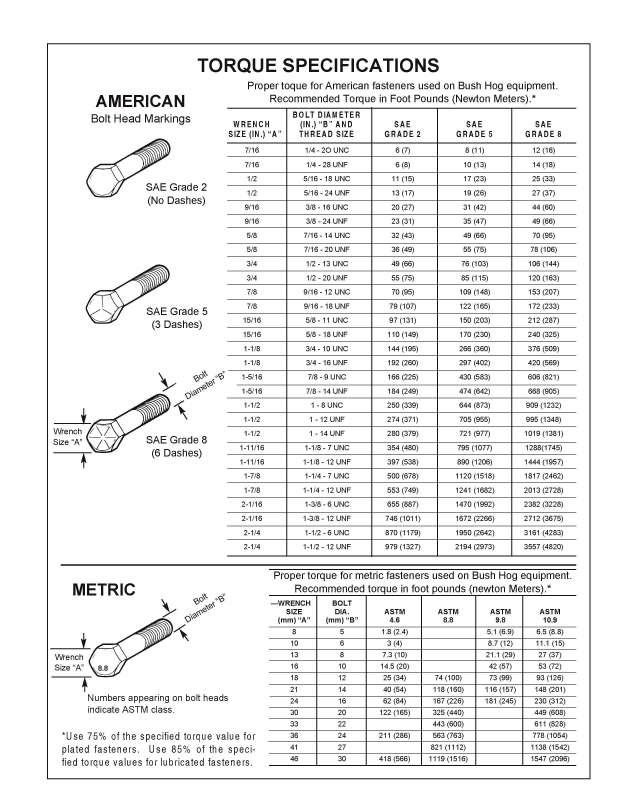
9 Page 7
10 Page 8


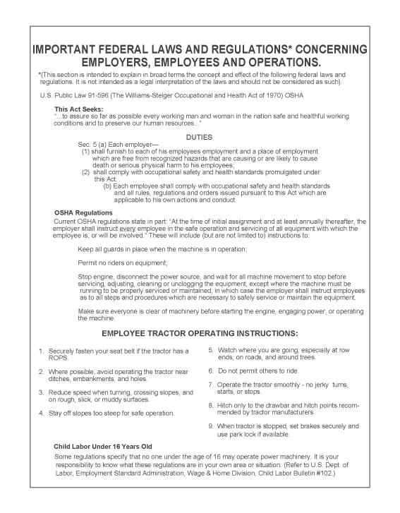
11 WARNING: Read and thoroughly understand all instructions and safety information before assembling or operating this post hole digger Failure to do so may cause serious injury or death. Do not allow anyone to operate this post hole digger who has not read this manual. As with all power equipment a post hole digger can be dangerous if assembled or used improperly. Do not operate this post hole digger if you have doubts or questions concerning safe operation. Si no entiende ingles, se prefiere que busque alguien que interprete las instrucciones para usted. INTENDED USE This product is designed to dig holes in the soil when attached to the 3-point linkage system and power-take-off of a tractor. It is not intended for any other use. Using the product for anything other than digging holes could result in serious injury or death. PERSONAL PROTECTIVE EQUIPMENT ALWAYS use appropriate personal protective equipment such as protective eyewear and safety shoes when operating this post hole digger. NEVER wear loose clothing or jewelry that could become entangled in the auger or driveline. SAFETY DECALS ALWAYS replace missing or defaced decals. Reorder from BUSH HOG. LOCATION: FRONT OF GEAR BOX LOCATION: SIDE OF GEAR BOX LOCATION: TOP OF BOOM ON TRACTOR END Page 9


12 LOCATION: PTO DRIVE SHAFT UNDER SHIELD NOTE: IF THE DRIVE SHAFT GUARD MENTIONED IN THE ABOVE DECAL IS MISSING,YOU MUST ORDER A REPLACEMENT BY CALLING BUSH HOG AT LOCATION: PTO DRIVE SHAFT SHIELD LOCATION: BOOM Post Hole Digger Decal Sheet BH # LOCATION: BOTTOM END OF BOOM ON TRACTOR END Page 0

13 LOCATION: TOP END OF AUGER TUBE NOTE: IF THE OUTPUT SHAFT GUARD MENTIONED IN THE ABOVE DECAL IS MISSING,YOU MUST ORDER A REPLACEMENT BY CALLING BUSH HOG AT GENERAL SAFETY AND PREPARATION ALWAYS make sure that anyone else who operates this post hole digger has read and understood the contents of the owner s manual and all safety decals on the product. ALWAYS be certain that all members of the work party are familiar with the operation of the digger and the hazards associated with it. ALWAYS check with authorities for underground utilities before digging a hole. Serious injury or death could result from contact with gas or electric lines. ALWAYS check the tractor owner s manual for instructions on operation, attachment of 3-point equipment and safety. ALWAYS make sure that all safety shields are in place and tightened down. Do not operate this post hole digger if any shields are missing. Contact BUSH HOG at for replacement part(s). ALWAYS make sure that the auger point and cutting edges are intact and in good working order before using this digger. NEVER allow children or other persons to ride on the Tractor or Implement. Falling off can result in serious injury or death. NEVER allow children to play on or around Tractor or Implement. Children can slip or fall off the Equipment and be injured or killed. Children can cause the Implement to shift or fall crushing themselves or others. Page
14 OPERATING SAFETY ALWAYS operate this post hole digger from the tractor seat.only one person should operate the digger. NEVER attach the post hole digger with the tractor engine running. NEVER operate the post hole digger with anyone near or in contact with any part of the implement, PTO driveline or auger. Serious injury or death could result from entanglement with moving parts. ALWAYS make sure that the tractor brake is set before digging a hole. ALWAYS keep hands, feet and clothing away from power-driven parts during operation. NEVER manually position the auger or manually force the auger into the ground. ALWAYS make sure that the tractor engine is shut off and the PTO drive is disengaged before leaving the tractor seat. NEVER move the tractor with the power-take-off in the ON position. NEVER exceed 540 RPM PTO operating speed. NEVER operate the post hole digger when the auger point is more than 6 in. above ground level. Operating the digger in elevated positions may cause the PTO driveline U joints to bind resulting in equipment damage and operator injury. ALWAYS turn off the digger immediately if an immovable object is encountered to prevent damage to the gear box or driveshaft and possible injury. A shear bolt is provided but may become welded to the input shaft if the driveshaft is left running after being sheared. REPAIR AND MAINTENANCE SAFETY ALWAYS perform maintenance operations such as lubrication, adjustments or repairs on the post hole digger with the tractor engine off, the PTO drive disengaged and the auger point resting on the ground. ALWAYS use the correct shear bolt (Grade 5). NEVER use or replace the shear bolt with one that is longer than the one specified in the manual (3/8 x 3 ). Periodically inspect all moving parts for wear and replace when necessary with authorized service parts. Look for loose fasteners, worn or broken parts, and leaky or loose fittings. Serious injury may occur from not maintaining this machine in good working order. Do not modify or alter this Implement. Do not permit another to modify or alter this Implement, any of its components or any Implement function. Any modification will void the warranty. Page 2
15 ASSEMBLY INSTRUCTIONS IMPORTANT: STEP : STEP 2: STEP 3: The gear box is shipped without lubricant. Fill the top hole with 80W-90 lubricant or the equivalent.fill until the lube appears at the side level check hole. Approximately two pints or two pounds of the lubricant is enough to lubricate the gears and bearings. A greater amount will not harm the gear box. Do not fill to overflow point as this may damage the seals. Be certain that the gear box has adequate lubrication. Check the oil level after every fifty hours of use. Attach the boom () to the top link mounting bracket on the tractor using a top link pin and a lynch pin (not provided) through the hole at the bottom of the boom. Connect the A frame (5) to the tractor s 3-point lift arms using the 7/8 in. pull pins with nut and lockwasher (7) as shown in the drawing. Attach the A frame (5) to the boom () after selecting the desired hole (for angle adjustment) using the A frame pin (6) and lynch pin (4). STEP 4: Attach the gear box (0) to the boom () using the boom pin (2). When in place secure with cotter pins (3). NOTE: Input shaft shield (9) and output shaft shield (8) are already attached to the gear box. STEP 5: STEP 6: ATTENTION: IMPORTANT: STEP 7: Attach the auger (8,9, 20, 2or 22) to the output shaft on the bottom of the gear box (0) using the /2 in. hex cap screws (5), /2 in. lockwashers (6) and /2 in. hex nuts (7). Tighten the nuts. Attach the driveline () to the gear box input shaft using the 3/8 in.x 3 in. grade 5 hex cap screw 2), the 3/8 in. lockwasher (3) and the 3/8 in.nc hex nut (4). Tighten the hex nut. Insert the /4 in. x 3/8 in. set screw (24) from the hardware kit in the hole on the yoke that aligns with the 3/6 in. groove on the gear box input shaft. Tighten loosely. THE 3/8 IN. HEX CAP SCREW PROVIDES SHEAR PROTECTION. USE A GRADE 5 3 IN. BOLT ONLY TO AVOID DAMAGE TO THE GEAR BOX OR AUGER. The universal joint should be greased with a good grade chassis lube every week. At the beginning of each season grease the sliding driveshaft members with a moly grease. All diggers are equipped with quickdetach universal joints on the power-take-off end for a -3/8 in. splined shaft. Attach the tractor end of the driveline () to the tractor PTO shaft. Push in the spring-loaded pin in the splined yoke and slip it on the splined PTO shaft of the tractor. Release the pin and push until it locks securely in place DO NOT USE ANY ADAPTERS BETWEEN THE TRACTOR OUTPUT SHAFT AND THE DRIVELINE YOKE. STEP 8: Check all nuts and bolts for tightness. Stabilizers should be kept tight to avoid side sway of the digger. LOCATION: TOP OF BOOM ON TRACTOR END Page 3


16 NOTE: See illustration A for reference in assembling the digger and mounting it to the tractor.note that the boom angle can be adjusted on your tractor for proper digging and ground clearance by moving the A frame to a different mounting hole as shown in illustration B. Angle Adjustment NOTE: When the 7/8 in. diameter pull pins in the A frame are too small for the holes in the lift arms, bushings should be used to obtain a proper fit. OPERATING INSTRUCTIONS ILLUSTRATION A ILLUSTRATION B WARNING: Read and thoroughly understand all instructions and safety information before operating this post hole digger Failure to do so may cause serious injury or death. Do not allow anyone to operate this post hole digger who has not read this manual. STEP : After mounting the digger to the tractor, lower the auger point slowly to the ground at the desired digging angle before engaging power. STEP 2: Engage the power-take-off and start digging at a slow speed, lowering the auger slowly as it begins to dig. STEP 3: Increase speed as the auger goes deeper. The type of soil will determine the proper auger speed. If the soil is extremely hard, it will generally improve operation to vary the speed of the auger at times. If an object is encountered which is too large for the auger to move, the digger will begin to vibrate. Withdraw the auger and remove the obstacle. STEP 4: When the auger has reached the desired depth, spin it momentarily at a high speed to clear the hole of dirt. Reduce speed before withdrawing the auger from the hole. STEP 5: Disengage the power-take-off after withdrawing from the hole and move the tractor to the next hole location. GENERAL MAINTENANCE REFER TO ILLUSTRATION C WARNING: Always perform maintenance operations with the tractor engine off, the PTO drive disengaged and the auger point resting on the ground.. To remove the auger from the gear box output shaft, take out the two /2 in. x 3 in. hex cap screws (5). 2. To remove the driveshaft from the gear box input shaft, take out the 3/8 in. x 3 in. shear bolt (2) and /4 in. set screw (24). 3. Lubrication of Gear Box Check the oil level after every fifty hours of use. Use 80W-90 lubricant and fill to oil level plug. All replacement lubricant should be of this type. 4. Lubrication of Driveline NOTE: The multi-purpose grease referenced in this section is NLGI Grade 2 type grease. BEFORE EACH USE a) Driveline Universal Joints- Apply multi-purpose grease to fittings. b) Driveline Guard- Apply 2-3 shots of multi-purpose grease to plastic fittings. c) Driveline Shaft- Disconnect PTO driveline, pull two sections apart, and apply thin coat of multi-purpose grease to inside of outer (female) section. Reassemble sections and install. Pull each section to be sure driveline and shields are securely connected. Make certain PTO shielding is in good condition. Page 4
17 PHD2202 POST HOLE DIGGER PARTS BREAKDOWN REFERENCE NUMBER PART NUMBER DESCRIPTION NUMBER REQUIRED PHD2202 PHD2202 Post Hole Digger Less Auger Boom Boom Pin 3 O / L 5/32 in. x -/2 in. Cotter Pin /6 in. Lynch Pi n " A" Fram e " A" Frame Pi n /8 in. Pull Pin with Nut and Lockwashe r Gear Box Output Guar d Gear Box Input Guar d Gear Box w/shield s Driveline with Plastic Shiel d A Driveline Guard Assembl y B Push Pin Yok e C Implement End Yok e D Cross and Bearing Ki t 2 E /4 in. x 3/8 in. Set Scre w /8 in. x 3 in. Hex Cap Screw (Grade 5 Shear Bolt ) /8 in. Lockwashe r /8 in. NC Hex Nu t /2 in. NC x 3-/2 in. Hex Cap Scre w /2 in. Lockwashe r /2 in. NC Hex Nu t in. Auge r in. Auge r in. Auge r in. Auge r in. Auge r Screw Point Owner's Manua l Canister, Owner's Manua l 26 O/ L 5/6 in. x in. Grade 2 Bolt Hardware Ki t Page 5

18 PHD2202 POST HOLE DIGGER ILLUSTRATION C See Illustration D for cutting edges and point. E NOTE: Safety shields are shaded on this diagram. NEVER operate the digger with any shield missing. Page 6
19 CUTTING EDGES AND POINT PARTS BREAKDOWN REFERENCE NUMBER PART NUMBER DESCRIPTION NUMBER REQUIRED* Carbide Cutting Edge varies by auger /2" x " UNC Carriage Bolt per cutting edge /2" UNC Lock Nut per cutting edge /2" x 3-/2" UNC Bolt /2"UNC Lock Nut Auger Point *NOTE:The number of cutting edges varies by auger size. Check your auger when ordering replacement cutting edges. See information below. ILLUSTRATION D 6 innumber of Cutting Edges Per Auger 6 in. (500666)- 2 9 in. ( )- 2 2 in.( )- 4 8 in.( ) in.( )- 6 2 in. auger (Ad Page 7
20 OPTIONAL ACCESSORIES WEIGHT MOUNTING KIT Assembly Instructions IMPORTANT SAFETY INFORMATION WARNING: Read and thoroughly understand all instructions and safety information before using this product. Failure to do so may cause serious injury or death. Always use appropriate personal protective equipment such as work gloves and safety shoes when using this product. CAUTION: Never use this product unless the weights are securely attached and locked down. Serious injury could result from falling weights. STEP : STEP 2: STEP 3: STEP 4: STEP 5: Remove the plugs from the digger boom. Place the threaded rod (2) through the hole. Attach a weight bar () on each side of the boom. Tighten the lock nuts (3) loosely. Adjust as required to level the weight bars. STEP 6: Tighten the lock nuts (3). STEP 7: Place the weights (purchased separately) on the weight bars (). STEP 8: Lock in place with the collars (4). Then tighten the set screw in each collar securely. REFERENCE NUMBER PART NUMBER DESCRIPTION NUMBER REQUIRED Weight Mount Kit Boom 2 -- Threaded Rod -- Weight Bar /8" Lock Nut Collar 2 -- Replacement Parts not available. Weight Kit Attached to Boom Weights Mounted on Digger Boom (not included)./2 diameter mounting hole required to fit weight bars. Page 8
21 OPTIONAL ACCESSORIES HYDRAULIC DOWN FORCE KIT Assembly and Operating Instructions IMPORTANT SAFETY INFORMATION WARNING: Read and thoroughly understand all instructions and safety information before using this product. Failure to do so may result in serious injury or death. Always use appropriate personal protective equipment such as work gloves, eye protection and safety shoes when using this product. Review all safety information and warnings in your post hole digger owner s manual. Be careful of pinch points between the digger and A-frame and the side plates. On light tractors, caution should be used to avoid lifting the back of the tractor. Only operate the post hole digger from the tractor seat. Do not allow people to be nearby when operating the digger and down force assembly. ASSEMBLY INSTRUCTIONS STEP : Mount the relief valve (7) to the hydraulic cylinder (5) using the 3/8 x /2 NPT nipple (6). It is recommended that a thread sealant be used on the threads. STEP 2: Mount the hydraulic cylinder (5) to the tab on the boom using the 3/4 x 2 bolt (0) and 3/4 lock nut (). STEP 3: Replace the pin holding the A-frame to the boom with the supplied 3/4 x 6 bolt (9). Mount the side plates ( & 2) as shown in the diagram using the small bushing (4) and 3/4 lock nut (). Make sure the spacers are placed correctly. STEP 4: Place the 3/4 x 6 bolt (9) and large bushing (3) in the middle hole of the plates shown in Illustration E. STEP 5: Mount the cylinder (5) into appropriate hole in the top of the side plates using 3/4 x 6 bolt (9) and small spacer bushing (4). NOTE: The range of holes on the top of the plates allows for adjustment for different tractors and different mounting holes in the boom. You may need to experiment to see which hole gives you the best range of motion with the down force kit. STEP 6: Tighten all the lock nuts () after final adjustment. Do not over tighten the top and bottom bolts to allow rotation. STEP 7: Connect the hydraulic hoses (8) to the relief valve (7). It is recommended that a thread sealant be used on the threads. STEP 8: Connect the hydraulic hoses (8) to the tractor as shown in Illustration F. Return Port (To Tank) Pressure Port (To Coupler) REFERENCE NUMBER PART NUMBER DESCRIPTION NUMBER REQUIRED Hydraulic Downforce Kit Left Side Plate Right Side Plate Large Downforce Bushing Small Bushing Assy., Hydraulic Cylinder 2 x H /8x/2 NPT Nipple Valve, Hydraulic Relief Assy, Hydraulic Hose - 60" LG /4"x 6" UNC Bolt /4"x 2" Bolt Illustration E /4" Lock Nut 4 Page 9
22 OPTIONAL ACCESSORIES HYDRAULIC DOWN FORCE KIT To Hydraulic Coupler (Tractor) Relief Valve To Hydraulic Tank (Marked Tank on valve) Illustration F OPERATING INSTRUCTIONS STEP : STEP 2: STEP 3: STEP 4: The cylinder is a single acting cylinder and must be plumbed correctly into the tractor hydraulic system to avoid damage and possible injury. It is recommended that the post hole digger be used without the down force kit in normal digging conditions. Down force assembly should only be used when difficult digging is encountered and only the force required should be used. When difficult digging is encountered, slowly engage the hydraulic down force assembly. Care should be used to only use the force required to slowly dig to avoid damage to the auger and cutting edges. When digging is complete, raise the auger using the 3-point controls. Hydraulic cylinder will retract. Page 20
23 SPECIFICATIONS Tractor Category Compact, Category and Category 2 Gear Box Special alloy pinion gears and tapered roller bearings on both sides of each gear Gears Heat-treated to Rockwell C30-40 to a depth of D riveline Equipped with quick-tach yoke to fit standard 6-spline PTO (completely shielded) Cutting Point Auger Boom A-frame edges Safety shields Shear Options pin Sold separately. Replaceable carbide Sold separately, Spiral tip 6 in., 9 in., 2 in., 8 in. and 24 in. sizes available 3-/4 in. O.D. high strength tubing with tapered rib and multiple holes for height adjustment 3-/4 in. high strength tubing On driveline, gear box "U" joint and gear box output shaft Replaceable. On input shaft to protect driveline, auger and gears Hydraulic down force kit and weight mounting kit Notes: Page 2
24
CPHD POST HOLE DIGGER Operator s/parts Manual. Table of Contents
 CPHD POST HOLE DIGGER Operator s/parts Manual Table of Contents Warranty Information... -3 Dealer Checklist... 4 Safety Precautions... 5-6 Federal Laws and Regulations... 7 Torque Specifications... 8 Important
MODEL M400 POST HOLE DIGGER
 MODEL M400 POST HOLE DIGGER MANUAL, OPERATORS & S THIS SAFETY ALERT SYMBOL IDENTIFIES IMPORTANT SAFETY MESSAGES IN THIS MANUAL. FAILURE TO FOLLOW THIS IMPORTANT SAFETY INFORMATION MAY RESULT IN SERIOUS
Post Hole Digger. Operation Manual MODEL
 Post Hole Digger MODEL 107798 Operation Manual This safety alert symbol identifies important safety messages in this manual. Failure to follow this important safety information may result in serious injury
Post Hole Diggers Compact Standard Heavy Duty
 Post Hole Diggers Compact Standard Heavy Duty MODEL 90 / MODEL 100 / MODEL 110 # 100623 # 100498 # 100624 Operation Manual This safety alert symbol identifies important safety messages in this manual.
PARTS MANUAL SECTION 46
 RTXG SERIES ROTARY TILLERS Published 08/16 MODELS RTX85G, RTX92G PARTS MANUAL SECTION 46 An Operator s Manual was shipped with the equipment. The Operator s Manual is an integral part of the safe operation
POST HOLE DIGGER. Operation, Service & Parts Manual For Models D20 & D40. FORM: D20_40DigRev.QXD
 POST HOLE DIGGER Operation, Service & Parts Manual For Models D20 & D40 FORM: D20_40DigRev.QXD September 2006 Revised August 2009 TABLE OF CONTENTS Introduction.............................1 Preparation..............................2
LIMITED WARRANTY DISCLAIMER OF IMPLIED WARRANTIES & CONSEQUENTIAL DAMAGES
 Published 08/15 LIMITED WARRANTY Bush Hog warrants to the original purchaser of any new Bush Hog equipment, purchased from an authorized Bush Hog dealer, that the equipment be free from defects in material
MODELS EWR820, EWR1023, EWR1227 PULL TYPE HAY RAKES PARTS MANUAL SECTION 19
 EWR MODELS EWR820, EWR1023, EWR1227 PULL TYPE HAY RAKES Published 04/11 PARTS MANUAL SECTION 19 MATERIAL HANDLING PARTS MANUAL PARTS ORDERING GUIDE The following instructions are offered to help eliminate
BUSH HOG. Model PHDC Post Hole Digger. OPERATION l MAINTENANCE 807 $
 BUSH HOG Model PHDC Post Hole Digger Operator s Manual OPERATION l MAINTENANCE 807 $4.00 50050175 CONGRATULATIONS! You have invested in the best implement of its type on the market today. The care you
ROTARY TILLER. Operation, Service & Parts Manual For "AS" Series. FORM: ASTillerBook.QXD
 ROTARY TILLER Operation, Service & Parts Manual For "AS" Series FORM: ASTillerBook.QXD April 2002 TABLE OF CONTENTS Preparation......................................1 Assembly Instructions.............................2
Prime Attachments & Custom Fab Brush Mower Owners/Operators Manual
 Prime Attachments & Custom Fab Brush Mower Owners/Operators Manual The operator is responsible for the safe operation and maintenance of the machine. It is important that anyone who uses the machine is
BUSH HOG SERIES 91 REAR MOUNTED BLADE
 BUSH HOG SERIES 91 REAR MOUNTED BLADE Operator s Manual ASSEMBLY l OPERATION l MAINTENANCE 12/08 $4.00 50064420 CONGRATULATIONS! You have invested in the best implement of its type on the market today.
SUNDOWN Operation. & Parts Manual. for Box Blade Models BB15-48, 60 BB20-48, 60, 72 BB30-60, 72, 84, & 96
 SUNDOWN Operation & Parts Manual for Box Blade Models BB15-48, 60 BB20-48, 60, 72 BB30-60, 72, 84, & 96 Operations and Parts Manual Table of Contents Section Page Table of Contents 2 Retail Customer Responsibility
TABLE OF CONTENTS DESCRIPTION. Safety Instructions & Safety Sign Locations Operating Instructions Assembly Instructions...
 TABLE OF CONTENTS DESCRIPTION PAGE Warranty... 1 Safety Instructions & Safety Sign Locations... 2 Operating Instructions... 3 Assembly Instructions... 5 500 & 600 Snowblower Drawings... 8 500 & 600 Snowblower
TABLE OF CONTENTS. Warranty Disclaimers Delivery Checklist After Sale Checklist Safety Set Up... 8
 TABLE OF CONTENTS Pickett Equipment Warranty... 2 Warranty Disclaimers... 3 Delivery Checklist... 4 After Sale Checklist... 4 Safety... 5-7 Set Up... 8 Machine Adjustments and Operation... 9 Maintenance
RED23305 Owner s Manual
 RED23305 Owner s Manual 5 foot, 3-Point Mounted Snow Blower 270 West Park Avenue Huron, SD 57350 866-526-5682 Serial Number: Date of Purchase: Red Devil Snow Blower See Figure 1. 1. The Red Devil Snow
PARTS MANUAL 3510, 3510-O, SECTION ROTARY MOWER
 , -O, ROTARY MOWER Published 0/ S MANUAL SECTION An Operator s Manual was shipped with the equipment. The Operator s Manual is an integral part of the safe operation of this machine and must be maintained
TRACTOR QUICK HITCH CATEGORY 2
 TRACTOR QUICK HITCH CATEGORY 2 Assembly & Operation Manual June 2007 Form: QuickhitchCat2 TABLE OF CONTENTS SECTION PAGE 1 Safety Information... 1 1.1 Training... 1 1.2 Before Operation... 1 2 Specifications...
WARRANTY REGISTRATION AND POLICY
 WARRANTY REGISTRATION AND POLICY Buhler Manufacturing products are warranted for a period of twelve (12) months from original date of purchase, by original purchaser, to be free from defects in material
Operator s Manual WARNING 9MF Si no entiende ingles, se prefiere que busque a alguien que interprete las instrucciones para usted.
 F8 Owner: Read this entire manual. This safety alert symbol is used throughout this manual to call your attention to messages involving your personal safety and the safety of others. Failure to follow
3-Pt. Quick Hitch. Owner s Manual
 3-Pt. Quick Hitch Owner s Manual WARNING: Read carefully and understand all ASSEMBLY AND OPERATION INSTRUCTIONS before operating. Failure to follow the safety rules and other basic safety precautions may
FLAIL MOWER SHREDDER
 FLAIL MOWER SHREDDER Operation, Service, & Parts Manual For Models: GML41, 49, 61, 69, & 79 February 2006 FORM: GMLMower.QXD TABLE OF CONTENTS Installation....................................................1
Operator s Manual. Go Galvanized! YOU'RE ALWAYS AHEAD...WITH A MODERN BEHIND.
 SUMMER 2008 C2 tilting grader blade Operator s Manual YOU'RE ALWAYS AHEAD...WITH A MODERN BEHIND. 003-5336 003-5342 003-5531 003-5544 P.O. Box 790 Beaumont, Tx 77704 409.833.2665 1.800.231.8198 Fax: 409.726.8333
AG PRODUCTS, LTD. YOU RE ALWAYS AHEAD... WITH A MODERN BEHIND.
 SUMMER 2016 BADGER DISC HARROW Operator s Manual 011-1156 011-1166 001-1501 001-1501-1 011-1167 001-1501-2 001-1501-3 011-1176 001-1501-4 011-1177 MODERN AG PRODUCTS, LTD. YOU RE ALWAYS AHEAD... WITH A
Model 35 PARTS MANUAL
 Model 35 PARTS MANUAL Version 3-2007 Ashland Industries Inc. 1115 Rail Drive P.O. Box 717 Ashland, WI. 54806 Ph: 877-634-4622 Toll Free Ph: 715-682-4622 Fx: 715-682-9717 www.ashlandind.com Model 35 Scraper
Operation and Parts Manual
 Operation and Parts Manual 3-Point PTO and Hydraulic Stump Grinders Models: SC-25 and SC-25H SC-50 and SC-50H Safety Operation Maintenance Repair Troubleshooting Parts Parts SC-50 and SC-50-H Stumpbuster
FERTILIZER SPREADERS MODEL PL180, PL400 & PL500
 FERTILIZER SPREADERS MODEL PL180, PL400 & PL500 SAFETY INSTRUCTIONS; OPERATING INSTRUCTIONS; PARTS BREAKDOWNS; ASSEMBLY; MAINTENANCE TABLE OF CONTENTS PAGE Introduction...1 Safety Decals...2 Checklists...3
Wood Chipper Model C550M Operator's Manual
 Wood Chipper Model C550M Operator's Manual THIS MANUAL MUST BE READ AND UNDERSTOOD BEFORE ANYONE OPERATES THIS MACHINE! Manual# 990023 Revised 01/2010 YOU MUST FILL OUT YOUR WARRANTY REGISTRATION TO ACTIVATE
Operator s Manual J20/80 9MJ Si no entiende ingles, se prefiere que busque a alguien que interprete las instrucciones para usted.
 J20/80 Owner: Read this entire manual. This safety alert symbol is used throughout this manual to call your attention to messages involving your personal safety and the safety of others. Failure to follow
CRUSTBUSTER OWNER / OPERATOR MANUAL
 CRUSTBUSTER OWNER / OPERATOR MANUAL MODEL # CB-1 CRUSTBUSTER Manufactured by: LEWIS BROTHERS MANUFACTURING, INC. Post Office Box 146 Baxley, GA 31513 Tel: (912) 367-4651 Fax: (912) 367-3958 5-2-17 1 INTRODUCTION
GRADING SCRAPERS INDUSTRIAL SERIES OPERATION, SERVICE & PARTS MANUAL FOR MODELS: GSI7-SS, GSI7, GSI8, GSI10, & GSI12.
 GRADING SCRAPERS INDUSTRIAL SERIES OPERATION, SERVICE & PARTS MANUAL FOR MODELS: GSI7-SS, GSI7, GSI8, GSI10, & GSI12 September 2006 FORM: IndGradingScrpr.QXD TABLE OF CONTENTS Safety Information......................1-2
LEWIS WINDROWER OWNER / OPERATOR MANUAL
 LEWIS WINDROWER OWNER / OPERATOR MANUAL MODEL # WR-1 WINDROWER Manufactured by: LEWIS BROTHERS MANUFACTURING, INC. Post Office Box 146 Baxley, GA 31513 Tel: (912) 367-4651 Fax: (912) 367-3958 2-21-14 1
ROTARY MOWER OPERATION, SERVICE & PARTS MANUAL FOR
 ROTARY MOWER OPERATION, SERVICE & PARTS MANUAL FOR L-G-40-40-P, L-G-48-40-P, L-G-60-40-P & L-G-72-40-P Slip Clutch Models: L-G-60-40-SC-P & L-G-72-40-SC-P February 2003 FORM: RotMwrBook.QXD TABLE OF CONTENTS
OWNER'S MANUAL L A W N R O L L E R PRT-481S BH. Safety Assembly Operation Repair Parts Maintenance. Visit us on the web!
 OWNER'S MANUAL L A W N R O L L E R ROLLER MODEL: PRC- BH PRT- BH PRT-S BH PRT-S BH Safety Assembly Operation Repair Parts Maintenance Recommended for use with Riding Mowers, Lawn or Garden Tractors, and
ROTARY TILLER. Operation, Service & Parts Manual For P-P/C Series. November 1996 (Rev. 4-05) FORM: PTillerBook.QXD
 FORM: PTillerBook.QXD") ROTARY TILLER Operation, Service & Parts Manual For P-P/C Series FORM: PTillerBook.QXD November 1996 (Rev. 4-05) TABLE OF CONTENTS Preparation......................................1 Assembly Instructions.............................2
ROTARY TILLER Operation, Service & Parts Manual For P-P/C Series FORM: PTillerBook.QXD November 1996 (Rev. 4-05) TABLE OF CONTENTS Preparation......................................1 Assembly Instructions.............................2
MAXILATOR OPERATOR'S MANUAL INLINE MOWER CADDY MODEL MBS RICE ROAD ROCKMART, GA (866) HAYBALE
 HAYBALE") MAXILATOR OPERATOR'S MANUAL INLINE MOWER CADDY MODEL MBS-80 51 RICE ROAD ROCKMART, GA 30153 (866) HAYBALE MAXILATOR EQUIPMENT, LLC Phone: (866) HAYBALE LIMITED WARRANTY Effective January 1, 2016 Maxilator
MAXILATOR OPERATOR'S MANUAL INLINE MOWER CADDY MODEL MBS-80 51 RICE ROAD ROCKMART, GA 30153 (866) HAYBALE MAXILATOR EQUIPMENT, LLC Phone: (866) HAYBALE LIMITED WARRANTY Effective January 1, 2016 Maxilator
PARTS MANUAL SECTION 105 FLEX WING ROTARY CUTTER. Published 09/14
 8 FLEX WING ROTARY CUTTER Published 09/ PARTS MANUAL SECTION 0 An Operator s Manual was shipped with the equipment. The Operator s Manual is an integral part of the safe operation of this machine and must
BEFCO. Operator s Manual POST HOLE DIGGER ACCESSORIES DOWN FORCE KIT. PHD-002 (fits models MOLE 300 & 400) PHD-005 (fits model MOLE 200) HOOKUP STAND
 PHD-005 (fits model MOLE 200) HOOKUP STAND") BEFCO Operator s Manual POST HOLE DIGGER ACCESSORIES DOWN FORCE KIT PHD-00 (fits models MOLE 300 & 400) PHD-005 (fits model MOLE 00) HOOKUP STAND 009-985 (fits models MOLE 00, 00, 300 & 400) POSITIONING
BEFCO Operator s Manual POST HOLE DIGGER ACCESSORIES DOWN FORCE KIT PHD-00 (fits models MOLE 300 & 400) PHD-005 (fits model MOLE 00) HOOKUP STAND 009-985 (fits models MOLE 00, 00, 300 & 400) POSITIONING
WOOD CHIPPER WC1103 5PQ (8/02/12)
") O P E R A T O R ' S M A N U A L WOOD CHIPPER WC1103 5PQ990101 (8/02/12) To the Owner; Thank-You for choosing a quality product from Frontier Equipment. We strive to give you the best equipment and the
O P E R A T O R ' S M A N U A L WOOD CHIPPER WC1103 5PQ990101 (8/02/12) To the Owner; Thank-You for choosing a quality product from Frontier Equipment. We strive to give you the best equipment and the
OPERATOR and PARTS MANUAL GRAIN GRINDER MODEL GG 7
 1 Serial # GG7-AUG10-71-1013 and Higher 2014 and up ROTO GRIND OPERATOR and PARTS MANUAL GRAIN GRINDER MODEL GG 7 ROTO GRIND BURROWS ENTERPRISES LLC 2024 East 8 th Street Greeley, Colorado 80631 970-353-3769
1000-LB. ENGINE STAND
 1000-LB. ENGINE STAND WARNING: Read carefully and understand all ASSEMBLY AND OPERATION INSTRUCTIONS before operating. Failure to follow the safety rules and other basic safety precautions may result in
Operator s Manual. Go Galvanized! YOU'RE ALWAYS AHEAD...WITH A MODERN BEHIND.
 SUMMER 2008 rock & landscape rake Operator s Manual 003-7445 003-7450 003-7460 003-7440 003-7445 003-7450 YOU'RE ALWAYS AHEAD...WITH A MODERN BEHIND. P.O. Box 790 Beaumont, Tx 77704 409.833.2665 1.800.231.8198
OPERATOR and PARTS MANUAL GRAIN GRINDER MODEL GG 10
 1 Serial # GG10-AUG10-6-0701 to GG10-AUG10-276-0314 ROTO GRIND OPERATOR and PARTS MANUAL GRAIN GRINDER MODEL GG 10 ROTO GRIND BURROWS ENTERPRISES, INC. 2024 East 8 th Street Greeley, Colorado 80631 970-353-3769
OXDALE PRODUCTS LTD POST HOLE BORER KEEP FOR FUTURE REFERENCE
 OXDALE PRODUCTS LTD POST HOLE BORER KEEP FOR FUTURE REFERENCE 1 Safety 1 Safety Signs 6 Mounting Instructions 7 Operating Instructions 11 Borer Operation 13 Special Operating Conditions 14 Removing the
PART'S MANUAL 3-POINT POSTHOLE DIGGER 130P, 240P, 340P, & 440P
 3-POINT POSTHOLE DIGGER 130P, 240P, 340P, & 440P Rev 05-07 PART'S MANUAL Part No. 01430870P An Operator's Manual was shipped with the equipment in the Manual Canister. This Operator's Manual is an integral
2000-LB. ENGINE STAND
 2000-LB. ENGINE STAND WARNING: Read carefully and understand all ASSEMBLY AND OPERATION INSTRUCTIONS before operating. Failure to follow the safety rules and other basic safety precautions may result in
WOOD CHIPPER WC1105 5PQ (8/08/2012)
") O P E R A T O R ' S M A N U A L WOOD CHIPPER WC1105 5PQ990102 (8/08/2012) To the Owner; Thank-You for choosing a quality product from Frontier Equipment. We strive to give you the best equipment and the
O P E R A T O R ' S M A N U A L WOOD CHIPPER WC1105 5PQ990102 (8/08/2012) To the Owner; Thank-You for choosing a quality product from Frontier Equipment. We strive to give you the best equipment and the
SPINNER SPREADER. Operation, Service & Parts Manual For Models S203L, S273L & S503L. May Form: Spnsprdr.PM65
 SPINNER SPREADER Operation, Service & Parts Manual For Models S20L, S27L & S0L May 200 Form: Spnsprdr.PM TABLE OF CONTENTS Welcome/Introduction... 1 Training... 1 PreOperation... 1 Spreader Assembly...2
1300 Dozer Owner s Manual & Parts Book
 300 Dozer Owner s Manual & Parts Book Purchase Date Serial Number Model Number Tractor Model Dealer PN: 3-2472 0--2008 Contents Description Page To The Owner 2 Maintenance & Caution 2 Safety Precautions
MAXILATOR OPERATOR'S MANUAL INLINE MOWER CADDY MODEL MBS RICE ROAD ROCKMART, GA (866) HAYBALE
 HAYBALE") MAXILATOR OPERATOR'S MANUAL INLINE MOWER CADDY MODEL MBS-80 51 RICE ROAD ROCKMART, GA 30153 (866) HAYBALE MAXILATOR EQUIPMENT, LLC Phone: (866) HAYBALE LIMITED WARRANTY Effective January 1, 2016 Maxilator
MAXILATOR OPERATOR'S MANUAL INLINE MOWER CADDY MODEL MBS-80 51 RICE ROAD ROCKMART, GA 30153 (866) HAYBALE MAXILATOR EQUIPMENT, LLC Phone: (866) HAYBALE LIMITED WARRANTY Effective January 1, 2016 Maxilator
Twin Screw Undercar Conveyor
 Twin Screw Undercar Conveyor Owner s Manual #19015700 05-00 Table of Contents Operator Qualifications...................................... 1 Safety.................................................. 2-4
SHEYENNE TELE-BOOM OWNERS MANUAL OPERATOR INSTRUCTIONS PARTS BOOK
 SHEYENNE TELE-BOOM OWNERS MANUAL OPERATOR INSTRUCTIONS PARTS BOOK 701 Lenham Ave. SW PO Box 647 Cooperstown ND 58425 1-800-797-1883 701-797-2700 * 701-797-2584 Fax www.sheyennemfg.com TABLE OF CONTENTS
TRUSS KITS FOR SPOUTING Installation Manual
 TRUSS KITS FOR SPOUTING Installation Manual LAMBTON CONVEYOR LIMITED 102 Arnold Street Wallaceburg, ON N8A 3P4 Canada Telephone: (519) 695-2316 Telephone: (519) 627-8228 ONE SOURCE ONE SOLUTION Toll free:
Part Number Mini Linear Lift Assembly Installation & Operator s Instruction Manual
 Part Number 39644 Mini Linear Lift Assembly Installation & Operator s Instruction Manual April 1999 MV1505C Chore-Time Warranty Mini Linear Lift Assembly Manual Chore-Time Warranty Chore-Time Equipment
3-Pt. Subsoiler. Owner s Manual
 3-Pt. Subsoiler Owner s Manual WARNING: Read carefully and understand all ASSEMBLY AND OPERATION INSTRUCTIONS before operating. Failure to follow the safety rules and other basic safety precautions may
p.t.o. Slip clutch Read this material before using this product. Failure to do so can result in serious injury. Save this manual.
 p.t.o. Slip clutch 65517 Installation Instructions Distributed exclusively by Harbor Freight Tools. 3491 Mission Oaks Blvd., Camarillo, CA 93011 Visit our website at: http://www.harborfreight.com Read
BOX SCRAPERS. Operation, Service & Parts Manual For Models: BB30-60, BB30-66, BB30-72, & BB FORM: BB30Scraper.QXD
 BOX SCRAPERS Operation, Service & Parts Manual For Models: BB30-60, BB30-66, BB30-72, & BB30-84 FORM: BB30Scraper.QXD September 2006 TABLE OF CONTENTS Introduction.............................1 Safety
WARRANTY REGISTRATION AND POLICY
 WARRANTY REGISTRATION AND POLICY Buhler Manufacturing products are warranted for a period of twelve (12) months from original date of purchase, by original purchaser, to be free from defects in material
G20/40. Owner s Manual G20/40 DANGER. Made in the U.S.A.
 G20/40 Made in the U.S.A. Owner: Date Purchased: G20/40 Model #: Serial #: Manual #: 9MG20402454105 DANGER Si no entiende ingles, se prefiere que busque a alguien que interprete las instrucciones para
Warnings and Precautions FAILURE TO READ, UNDERSTAND AND FOLLOW THESE INSTRUCTIONS MAY LEAD TO SERIOUS INJURY OR DEATH!
 Instruction Booklet 2006 Summit ATV Pak-Mule Single Axle 84000 Summit ATV Pak-Mule Tandem Axle 84002!! READ ME FIRST!!! Please read carefully BEFORE using you new Summit ATV Product. Congratulations! You
Operator s Manual POST HOLE DIGGERS PHD100, PHD200, PHD300 & PHD400
 olqljb`= =rp^ Operator s Manual POST HOLE DIGGERS PHD00, PHD00, PHD300 & PHD00 Before you begin use of equipment, read, understand, and follow all safety instructions in this manual. The operator s manual
1 TO THE PURCHASER TABLE OF CONTENTS SERVICE & PREPARATION... 5
 SAFETY ALERT SYMBOL This is the Safety Alert Symbol used by this industry. This symbol is used to warn of possible injury. Be sure to read all warnings carefully. They are included for your safety and
MODEL 5500 Tire Repair Station
 MODEL 5500 Tire Repair Station Installation, Operation and Repair Parts Information Branick Industries, Inc. 4245 Main Ave P.O. Box 1937 Fargo, North Dakota 58103 P/N: 81-0047C TABLE OF CONTENTS SAFETY
POST HOLE DIGGER OWNER S/ OPERATOR S MANUAL MODEL NO CAUTION For Safe Operation Read Rules And Instructions Carefully
 OWNER S/ OPERATOR S MANUAL MODEL NO. 500 CAUTION For Safe Operation Read Rules And Instructions Carefully STANDARD DUTY 3-PT. MOUNTED POST HOLE DIGGER SI NO LEEINGLES, PIDA AYUDA A AIGUIEN QUE SI LO LEA
3-Pt. Boom Pole. Owner s Manual
 3-Pt. Boom Pole Owner s Manual WARNING: Read carefully and understand all ASSEMBLY AND OPERATION INSTRUCTIONS before operating. Failure to follow the safety rules and other basic safety precautions may
OPERATOR S MANUAL MODEL GC-SFZ
 R Made in the USA by MODEL GC-SFZ THIS MANUAL CONTAINS THE OPERATING INSTRUCTIONS AND SAFETY INFORMA- TION FOR YOUR SCAG ACCESSORY. READ- ING THIS MANUAL WILL PROVIDE YOU WITH MAINTENANCE AND ADJUSTMENT
John Deere Tractors MANUAL
 John Deere 800-820 Tractors MANUAL 202 John Deere 800-820 Tractors Blade, pivot frame Cylinders & Hydraulics Main Frame, Brackets, Mounting Safety, Operation, Maintenance 9 Attachments Warranty 2 22 Industrial
84in. Driveway Drag. Owner s Manual
 84in. Driveway Drag Owner s Manual WARNING: Read carefully and understand all ASSEMBLY AND OPERATION INSTRUCTIONS before operating. Failure to follow the safety rules and other basic safety precautions
OPERATOR S MANUAL FABRIC 3-BAG GRASS CATCHER PART NO PRINTED 8/2012 PRINTED IN USA
 OPERATOR S MANUAL FABRIC -BAG GRASS CATCHER Models: GC-STC-V This manual contains the operating instructions and safety information for your Scag mower accessory. Reading this manual can provide you with
Operator's Manual. VC-60 & VC-60 Plus Harper Industries, Inc. 7/03 Part No
 Operator's Manual VC-60 & VC-60 Plus 2003 Harper Industries, Inc. 7/03 Part No. 970066 Thank you for purchasing a Harper/Goossen Verti-Cutter. As with all Harper/Goossen products, the Harper/Goossen Verti-Cutter
1000-LB. MOTORCYCLE LIFT TABLE OWNER S MANUAL
 1000-LB. MOTORCYCLE LIFT TABLE OWNER S MANUAL WARNING: Read carefully and understand all ASSEMBLY AND OPERATION INSTRUCTIONS before operating. Failure to follow the safety rules and other basic safety
OWNER S GUIDE 8A DURALIFT II 13,200 LB. CAPACITY. Link Mfg. Ltd th St. N.E. Sioux Center, IA USA
 OWNER S GUIDE 8A000715 DURALIFT II 13,200 LB. CAPACITY Link Mfg. Ltd. 223 15th St. N.E. Sioux Center, IA USA 51250-2120 www.linkmfg.com QUESTIONS? CALL CUSTOMER SERVICE 1-800-222-6283 DEALER / INSTALLER:
MODEL EF Full Circle Tire Spreader
 MODEL EF Full Circle Tire Spreader Installation, Operation & Repair Parts Information Branick Industries, Inc. 4245 Main Avenue P.O. Box 1937 Fargo, North Dakota 58103 REV. 062917 P/N: 81-0050C CAUTION
610 BUSHEL MANURE SPREADER
 610 BUSHEL MANURE SPREADER RODA MANUFACTURING 1008 LOCUST ST. HULL, IA. 51239 Art s-way Manufacturing 712-439-2366 Co., Inc. Hwy 9 West - PO Box 288 WWW.RODAMFG.COM Armstrong, IA. 50514 U.S.A 2 INTRODUCTION
MK AUGERS POWER SWING KIT ASSEMBLY & OPERATION MANUAL
 MK AUGERS POWER SWING KIT ASSEMBLY & OPERATION MANUAL Read this manual before using product. Failure to follow instructions and safety precautions can result in serious injury, death, or property damage.
RVT SERIES HEAVY DUTY TRIPPING SNOW PLOW
 RVT SERIES HEAVY DUTY TRIPPING SNOW PLOW Model: Serial Number: Rev. 10/13 Rylind Manufacturing, Inc. 2801 Youngfield St Suite 250 Golden, CO 80401 Main Offices: 303-979-3548 Manufacturing Plant: 970-522-2859
PART'S MANUAL. Rear Mounted Blade RHINO
 850 Revised 06-10 PART'S MANUAL Rear Mounted Blade Part No. 00787017P An Operator's Manual was shipped with the equipment in the Manual Canister. This Operator's Manual is an integral part of the safe
W & A 12 ROW TOP LEVELING STACKER LEVEL BANDER
 W & A 12 ROW TOP LEVELING STACKER LEVEL BANDER NO. 3640 OPERATOR S MANUAL TO THE OWNER: Congratulations on your purchase of a new W & A Top Leveling Stacker Level Bander. Your selection is an indication
I-175 PARTS MANUAL Version 4-04
 I-175 PARTS MANUAL Version 4-04 Ashland Industries Inc. 1115 Rail Drive P.O. Box 717 Ashland, WI. 54806 Ph: 877-634-4622 Toll Free Ph: 715-682-4622 Fx: 715-682-9717 www.ashlandind.com Model I-175 Scraper
MODEL L/R/EF Sectional Tire Spreader
 MODEL L/R/EF Sectional Tire Spreader Installation, Operation & Repair Parts Information Branick Industries, Inc. 4245 Main Avenue P.O. Box 1937 Fargo, North Dakota 58103 REV08032016 P/N: 81-0195E TABLE
Operator s Manual POST HOLE DIGGERS PHD100, PHD200, PHD300, PHD400
 olqljb`= =rp^ Operator s Manual POST HOLE DIGGERS PHD100, PHD200, PHD300, PHD400 Before you begin use of equipment, read, understand, and follow all safety instructions in this manual. The operator s manual
OPERATIONS MANUAL & PARTS LIST MODEL: 300UT 3 CU. FT. 1 of 8
 OPERATIONS MANUAL & PARTS LIST MODEL: 300UT 3 CU. FT. WS537 2-2012/Rev.A 104 S. 8th Ave. Marshalltown, IA Phone 800-888-0127 / 641-753-0127 Fax 800-477-6341 / 641-753-6341 www.marshalltown.com 1 of 8 INTRODUCTION
MODEL NO & UP SAFETY INSTRUCTIONS. Keep this Operator s Manual in the plastic tube behind the operator seat.
 FORM NO. 94-7276 MODEL NO. 41026-60101 & UP OPERATOR S INSTRUCTIONS HOSE REEL KIT To assure maximum safety, optimum performance, and to gain knowledge of the product, it is essential that you or any other
OPERATOR S MANUAL MODEL GC-STC-V
 MODEL GC-STC-V THIS MANUAL CONTAINS THE OPERATING INSTRUCTIONS AND SAFETY INFORMA- TION FOR YOUR SCAG ACCESSORY. READ- ING THIS MANUAL WILL PROVIDE YOU WITH MAINTENANCE AND ADJUSTMENT PROCEDURES TO KEEP
W & A 12 ROW TOP LEVELING STACKER LEVEL BANDER
 W & A 12 ROW TOP LEVELING STACKER LEVEL BANDER NO. 3640 OPERATOR S MANUAL TO THE OWNER: Congratulations on your purchase of a new W & A Top Leveling Stacker Level Bander. Your selection is an indication
Airflo MANUFACTURING CO., INC.
 Airflo MANUFACTURING CO., INC. 365 UPPER OAKWOOD AVE, ELMIRA NY 14903 PHONE: 607-733-8284 / FAX: 607-733-0587 OPERATOR & PARTS MANUAL PSV-8L ELECTRIC SPREADER Visit our website at www.air-flo.com Contents
3308, 3308SH PARTS MANUAL SECTION ROTARY MOWER
 0, 0SH ROTARY MOWER Published / PARTS MANUAL SECTION 0 An Operator s Manual was shipped with the equipment. The Operator s Manual is an integral part of the safe operation of this machine and must be maintained
Rotary Mowers. Instruction Book
 Instruction Book Rotary Mowers Manufactured By: Helm Welding (1983) Limited 86386 Lucknow Line PO Box 158 Lucknow, Ontario, Canada NOG 2HO TEL: (519) 529-7627 or 529-7000 FAX: (519) 529-3260 Email: inquiry@lucknowproducts.com
03-SERIES 4 & 6-ROW RIGID & FOLDING PEANUT VINE CONDITIONER OPERATOR S MANUAL THIS MANUAL TO ACCOMPANY MACHINE
 03-SERIES 4 & 6-ROW RIGID & FOLDING PEANUT VINE CONDITIONER OPERATOR S MANUAL THIS MANUAL TO ACCOMPANY MACHINE PART NO. 03-OM-03 Printing Date: SEPT 2012 WARRANTY POLICY KELLEY MANUFACTURING COMPANY (KMC)
3-Pt. Box Scraper. Owner s Manual
 3-Pt. Box Scraper Owner s Manual WARNING: Read carefully and understand all ASSEMBLY AND OPERATION INSTRUCTIONS before operating. Failure to follow the safety rules and other basic safety precautions may
Pro Shot Grease Dispense Valve
 Instructions Parts List Pro Shot Grease Dispense Valve 309032J For high pressure grease dispense. 8000 psi (55 MPa, 552 bar) Maximum Working Pressure Model No. 242055, Series B, 1/4 npt Fluid Inlet Model
Richmond Conveyor. Hydraulic Ultimate Manual. January 2013
 Richmond Conveyor Hydraulic Ultimate Manual January 2013 Table of Contents Operators Manual Removing conveyor from truck Maintenance checklist Maintenance kit material list Safety information Index Installation
WARRANTY REGISTRATION AND POLICY
 WARRANTY REGISTRATION AND POLICY Buhler Manufacturing products are warranted for a period of twelve (12) months from original date of purchase, by original purchaser, to be free from defects in material
Operator s Manual & Repair Parts Manual. Do Not Use or Operate This Equipment Until You Have Read and Understand This Manual
 Operator s Manual & Repair Parts Manual Do Not Use or Operate This Equipment Until You Have Read and Understand This Manual The purpose of this manual is to explain maintenance requirements and adjustments
Warranty Information Operators Manual Installation Instructions. Sudenga
 Warranty Information Operators Manual Installation Instructions Sudenga Rust Sales, Inc. 2964 164 th Ave SE Harwood, ND 58042 (800) 478-7801 (701) 282-9194 www.hopperwalker.com Limited Warranty Statement
THE VERSA-DRILL 3-POINT MOUNTED NO-TILL DRILL; ATV-PULL TYPE DRILLS
 THE VERSA-DRILL 3-POINT MOUNTED NO-TILL DRILL; ATV-PULL TYPE DRILLS Models KVGT-489, KVGT-728, KVGA-489 170 West 600 North Shelbyville, Indiana 46176 800.458.9129 www.kascomfg.com THANK YOU! You have invested
PARTS MANUAL SECTION. Models 295, 296, 297, 1297 ROTARY MOWER
 0 Series Models,,, ROTARY MOWER Published 0/ PARTS MANUAL SECTION An Operator s Manual was shipped with the equipment. The Operator s Manual is an integral part of the safe operation of this machine and
WARNING this attachments capacity changes depending on the Skid Steer Loader it is hooked up to. CAPACITY AT 24 LOAD CENTER
 SKID STEER FORKLIFT ATTACHMENT Any piece of equipment can be dangerous if not operated properly. YOU are responsible for the safe operation of this equipment. The operator must carefully read and follow
MOBILE 4 AUGER MIXER OWNER S MANUAL
 MOBILE 4 AUGER MIXER OWNER S MANUAL Transcanadian Highway, Exit 170 230 Industriel Blvd, St-Germain Quebec, Canada J0C-1K0 Tel.: (819)395-4282 Fax : (819)395-2030 www.valmetal.com 1997/06 info@valmetal.com
OPERATOR S MANUAL. Operator Controlled Discharge Chute STT-OCDC-61V Scag Power Equipment Division of Metalcraft of Mayville, Inc.
 OPERATOR S MANUAL Operator Controlled Discharge Chute Models: STT-OCDC-52V STT-OCDC-61V This manual contains the operating instructions, assembly instructions and safety information for your Scag accessory.