Supercharging INDUCTION. Its purpose is to increase the mass of the air/fuel charge going into the engine for each revolution.
|
|
|
- Candace Hood
- 5 years ago
- Views:
Transcription
1 Supercharging INDUCTION Its purpose is to increase the mass of the air/fuel charge going into the engine for each revolution.
2 Most supercharged engines also have constant speed propellers They are designed to keep full power, manifold pressure at or above sea level pressure for as high as possible, hence the term Altitude Engine
3 Critical altitude = that altitude where the boosted manifold pressure can no longer exceed sea level pressure. As system technology developed we eventually designed supercharged engines that exceeded ambient pressure in the intake system.
4 This can also be done at lower altitudes for maximum power during critical flight operations, Is sometimes used for limited duration s. Maximum boost is determined by the strength of the intake system, or the detonation characteristics of the engine
5 General gas law = volume of a gas is inversely proportional to the absolute pressure and is directly proportional to the temperature. (V1 * P1) / T1 = (V2 * P2) / T2
6 Many things create high cyl pressure. 1. Advanced ignition timing 2. High density air 3. Low octane, hot burning fuels 4. Excessive compression (wrong engine parts) 5. High intake temperatures
7 High pressure creates high temperature. At a certain temperature and pressure threshold, the pressure shock wave, which travels faster then the heat/burn wave, starts to spontaneously ignite the air/fuel mixture in an uncontrolled fashion.
8 This is called detonation, - FAA declares this to be a state of uncontrolled burning. Pre-ignition is when any source ignites the air/fuel charge prior to the spark plug ignition.
9 Air Density INDUCTION Standard day conditions = at sea level, at 15 c or 59 f, at 45 N lat. Factors effecting density Water and hi temps displace air molecules creating less density.
10 Avogadro s law states that any gas molecule will take up the same space at the same temperature. N2 has about twice the mass per molecule as H2O therefore the wet air has less mass per unit of volume. (Lower density)
11 Density altitude = common pilot nomenclature, higher numbers means lower density.
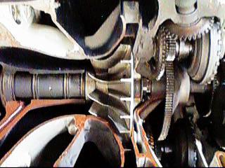
12 Supercharger is a non-positive displacement centrifugal air pump (compressor) that increases the air density in the intake systems and the cylinders. Can be single or multi speed up to 13 to 1 ratio to crankshaft, in low blower up to 42 inhg. hi blower = up to 80 inhg
13 When switching to high speed the manifold pressure will go up and oil pressure will drop. Supercharging is the overall term for pumping air into the engine regardless of how this is accomplished.
14 But is also the term for mechanically pumping air with a gear driven compressor. (Some auto racing applications use a 4 wide belt drive) Turbo supercharging uses exhaust to drive a turbine/compressor pump.
15 In most super chargers fuel is mixed with air before supercharging (internal), but not all (external). This helps to vaporize the fuel. Turbo superchargers have the air compressed prior to fuel metering
16 If engine cannot boost above 30.00"Hg then it is a normalized boosted engine. It can be said the normalized engine regains normal ambient pressure, up to the point where the turbo is at maximum output.
17 Those that go above 30.00"Hg are known as supercharged. Intercooler can be used on superchargers to cool the air charge after the compressor
18 With some engines there is a distribution impeller, but this not a charging impeller. (more later) On the R-985 it has an actual supercharger impeller at a 7.5 to 1 ratio to the crankshaft.
19 It is possible to have superchargers that have several stages of charging much like a turbine engine, and, or they can have several speeds of compressor RPM. Stages and speeds. Can have Stages: Speeds: 2 2 1
20 More then one compressor impeller creates the multiple stages Only the gear driven Supercharger can have different speeds (Automatic Gear box).
21
22 Dual speeds are controlled by solenoid switch. Engine must have low compression ratios to prevent blow ups with high pressures. Supercharger clutches are engaged with oil pressure.
23 Supercharging casing can be airfoil, vaned, venturies Supercharger efficiency is by speed of rotation, and size of impeller
24 Advantages 1. More hp, 2. shorter takeoff, 3. bigger payload, INDUCTION 4. Greater fuel efficiency, 5. higher altitude
25 Disadvantages, INDUCTION 1. premature engine wear, 2. more pre ignition and detonation, 3. closer monitoring and maintenance,
26 4. must use higher fuel grades, 5. Harder to work on higher costs, 6. low altitude restrictions due too much boost.
27 A condition, less severe than bootstrapping, is called "overshoot", where the turbo overshoots the engine one time during hard throttle application.
28 Need to beef up the engine to handle the turbocharger or supercharger. Intercooler is heat exchanger that cools air before going into engine to increase density.
29 Two common current producers of turbosuperchargers are Ray-Jay and Garrett AirResearch.
30 RayJay were the original type of turbo, with electric on/off solenoid, then came the automatic controls. VAPC, APC, Density controller, Distribution impeller = a mixing impeller, connected directly to the crankshaft that does not provide any boosting capacity.
31 Never install a supercharger onto an engine that was not designed from the ground up to be supercharged. Conversions always loose reliability and longevity, and increase the possibility of sudden catastrophic engine departation.
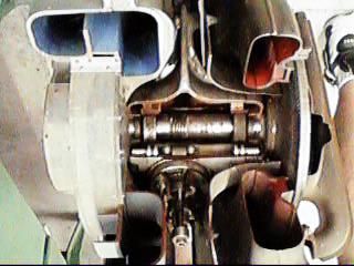
32 Supercharger and *Turbosupercharger components. 1. Compressor housing 2. *Turbine housing 3. Compressor impeller 4. *Turbine impeller 5. Drive shaft
33 6. Transmission assembly (Geared superchargers only) 7. Diffuser 8. Bearing sections 9. Lubrication plumbing 10. Air ducting 11. *Exhaust ducting 12. Control systems
34 Compressor housing is made of cast aluminum, cast, then machined. Compressor impeller, centrifugal, is the upper deck pressure side, directs air from the center to the outside. Turbine housing, cast iron or steel,
35 Turbines are impulse or reaction types, can be lost wax investment casted then machined or ground to final shape. Investment casting will lessen the porosity of the casting.
36 Turbine temperatures are normally 1,700 f Turbo superchargers can operate at speeds up to 100,000 RPM.
37 Drive shaft connects the compressor impeller to the transmission assembly or to the drive turbine impeller. Transmissions are either simple geared drivelines or they can be multi-speed transmissions that are hydraulically, or electro-hydraulically controlled.
38 These latter units will include a clutch systems coupled to a sun/planetary gear system, similar to an automatic automotive transmission. Diffusers are two main types: 1. Airfoil converging/diverging duct 2. Straight vane
39 The venturi-type diffuser is equipped with plain surfaces, This type has been most widely used on medium powered, supercharged engines On large volume engines ranging from 450 hp upwards, either a vane or airfoil type diffuser is widely used.
40 Bearing housing, is usually either a floating type plain bearing with pressurized oil (turbo superchargers) or they may use a double set of ball bearings with an oil bath spray. Shaft RPM can be as high as 40,000 to 50,000 RPM on some turbo superchargers.
41 Lubrication plumbing includes standard AN hardware, hoses, and tubing, designed to handle petroleum products at or below 100 psi. The impeller shaft and gear are usually forged integrally of very high grade steel.
42 Air ducting can be anything from high pressure scat tubing to cast aluminum runners and distribution manifolds. This all needs to be considerably stronger than normally aspirated induction assemblies. Do not interchange these parts.
43 Exhaust ducting is usually made from the same materials (Stainless Steel) as the rest of the exhaust system. Since the system has so much motion from vibration and heat expansion there will probably be flex, or expansion joints installed.
44 This may be encased in heat shielding of some form, particularly when installed on aircraft with streamlined cowlings. DO NOT leave this shielding off the aircraft for any flight operations.
45 Control systems INDUCTION Some early systems were manually controlled via a push/pull vernier near the throttle control.
46 During specific altitude and power conditions the pilot would engage the supercharger clutches via oil pressure controls, or start closing the turbosupercharger wastegate.
47 Wastegate is a device used on turbo superchargers that allows exhaust gasses to bypass the drive turbine. Typically a closed wastegate means full turbine output, (the bypass is closed). Deck pressure is that pressure just after the compressor.
48 Throttle valve is between compressor and intake system. Fuel is injected into intake close to intake valves.
49 Several systems are described in the following slides. There are numerous configurations. They all function by use of pressure control or density control, or both. They can regulate waste gates or scroll valves.
50 A density regulator will measure for pressure and temperature. A pressure regulator will only regulate for pressure. The most simple system is a outside adjustable bypass screw.
51 Other smaller systems may rely on only density regulation. As temperature or pressure changes the oil pressure is allowed to build or release on the wastegate controller. These usually default to open with no pressure.
52 These controllers are on the return side of the actuator. Pressure controllers can measure pressure, density or be differential, comparing two differing pressures.
53 One Lycoming system has four main components 1. Turbo supercharger 2. Density controller 3. Differential controller 4. Bypass assembly (wastegate)
54 Turbo supercharger is a sea level boosted engine with a critical altitude of 19,000 ft. Density controller controls oil pressure of wastegate actuator only during full power operation. It is density sensing, temp. and press.
55 Bellows regulates oil valve when deck pressure is below maximum output for those conditions. Differential controller controls oil pressure of wastegate actuator by means of a differential diaphragm with deck pressure on one side and post throttle MAP on the other side.
56 The differential controller will try to maintain a pressure drop across the throttle valve of 2-4 Hg. When it opens the waste gate opens. This valve will remain closed during wide open throttle operation since there is not enough differential to open it.
57 Another system uses a variable-pressure controller instead of a density and differential controllers. This device works similar to the differential controller but it also has a cam and plunger that is actuated by throttle linkage.
58 Over high deck pressure pushes the poppet down and open on the top end, and the cam pushes the poppet follower up and open from the bottom end during lower power settings. A vacuum filled bellows and several balancing springs work to keep the poppet valve closed. Unliscensed copyrighted material - W. North 1998 Unliscensed copyrighted material - W. North 1998
59 Continential had earlier units which used three controllers and later units combined these into one unit with cam/throttle linkages. These are: absolute pressure controller rate of change controller pressure-ratio controller
60 In similar fashion as they bleed off waste gate control oil opening the waste gate. They are hooked up in parallel so that each may independently dump exhaust gas.
61 Absolute pressure controller is a maximum upper deck pressure limiter. Rate of change controller bypasses wastegate oil if the deck pressure changes faster then 6.5 in Hg/S
62 The engine can over boost momentarily during rapid throttle application. This may only oscillate the power, or it may cause detonation for a short period.
63 Pressure ratio controller will maintain a pressure ratio between the deck pressure and inlet ram air of 2.2:1 at any altitude above 16,000 ft. This prevents excessive heat buildup in the deck airstream which can cause detonation.
64 The variable absolute pressure controller combines these three units and it functions in a manner identical to the Lycoming variable controller. This system also incorporates a overpressure MAP relief valve.
65 It uses varible fuel pressure as the operating force. Another turbo supercharger control system uses an adjustable orifice that also includes an overpressure relief valve
66 Adjustment criteria, at component replacement, or engine overhaul Test run on ground, Calibrate MAP gauge, Slowly advance throttle watching MAP
67 Install thermocouple to know temperature at specified port in compressor, then use chart to check temp against pressure read. Slow smooth throttle movement.
68 Frequent oil changes for any turbo supercharged engines. Plan on higher service requirements inspection wise as well. One quote is $1.50 per hour flight time in additional costs.
69 Bootstrapping is when as you increase power, turbo increases more, then you are over powered in a cyclic manner. It is an undesirable cycle of turbocharging events causing the manifold pressure to drift in an attempt to reach a state of equilibrium.
70 Bootstrapping occurs when the waste gate is closed or mostly closed. Rapid movement of the throttle can cause a certain amount of manifold pressure drift in a turbocharged engine. Bootstrapping is when the drift persists.
71 Intercoolers may exist on any of these devices. They provide pressurized intake air cooling. Sonic venturis are used to increase cabin air volume input, sacrificing limited amounts of air pressure.
72 Over boost is when the MAP upper pressure limit has been exceeded. This will break parts, cause detonation and break more parts.
73 Turbo compounding The turbocompound engine consists of a conventional, reciprocating engine in which exhaust driven turbines are coupled to the engine crankshaft.
74 This system of obtaining additional power is sometimes called a PRT (power recovery turbine) system. Power recovery turbine systems, because of weight and cost considerations, are used exclusively on very large reciprocating engines.
75 The net yield from them is not sufficient to justify their use on smaller engines.
76
77 Turbo supercharger problems 1. Aircraft fails to reach critical altitude. 2. Exhaust system leaks. 3. Faulty turbocharger bearings. 4. Waste gate will not close fully. 5. Waste gate will not open.
78 6. Engine surges. 7. Bootstrapping. INDUCTION 8. Waste gate malfunction. 9. Controller malfunction. 10. Waste gate bypass valve bearings tight. 11. Oil inlet orifice blocked. 12. Broken waste gate linkage.
79 Differential controller malfunctions. 1. Seals leaking. 2. Diaphragm broken. 3. Replace controller. 4. Controller valve stuck.
80 Density controller malfunctions. 1. Bellows damaged. 2. Valve stuck.
Induction, Cooling, & Exhaust Aviation Maintenance Technology
 Induction, Cooling, & Exhaust Aviation Maintenance Technology INDUCTION Induction = There are two basic types 1. 2. Non-supercharged components 1. 2. 3. 4. 5. 6. 7. 8. Air Scoop Air filters. Ducting Hot
Induction, Cooling, & Exhaust. Aviation Maintenance Technology 111 B B
 Induction, Cooling, & Exhaust Aviation Maintenance Technology 111 B - 112 B Unliscensed copyrighted material - W. North 1998 Unliscensed copyrighted material - W. North 1998 Induction = those locations
2. Turbocharger System
 INTAKE (INDUCTION) 2. Turbocharger System A: GENERAL The turbocharger system consists of a water-cooled turbocharger, air-cooled intercooler, wastegate control solenoid valve, etc. The turbine rotated
Air Scoop Usually a converging duct that will make use of the ram air effect of the aircraft s motion.
 1 Induction & Fuel Metering Aviation Maintenance Technology 253-254 2 Induction = those locations of the engine nacelles where air entering cannot avoid entering the cylinders. There are two basic types
Common Terms Selecting a Turbocharger Compressor... 4
 TURBOCHARGERS Common Terms... 2 Adiabatic Efficiency... 2 Pressure Ratio... 2 Density Ratio... 2 Turbine... 2 A/R Ratio... 2 Charge-Air-Cooler... 2 Boost... 3 Waste Gate... 3 Turbo Lag... 3 Boost Threshold...
E - THEORY/OPERATION - TURBO
 E - THEORY/OPERATION - TURBO 1995 Volvo 850 1995 ENGINE PERFORMANCE Volvo - Theory & Operation 850 - Turbo INTRODUCTION This article covers basic description and operation of engine performance-related
POWERPLANT. 1. by cylinder arrangement with respect to the crankshaft radial, in-line, v-type or opposed, or
 This chapter covers the main systems found on small airplanes. These include the engine, propeller, and induction systems, as well as the ignition, fuel, lubrication, cooling, electrical, landing gear,
So how does a turbocharger get more air into the engine? Let us first look at the schematic below:
 How a Turbo System Works Engine power is proportional to the amount of air and fuel that can get into the cylinders. All things being equal, larger engines flow more air and as such will produce more power.
Chapter 6. Supercharging
 SHROFF S. R. ROTARY INSTITUTE OF CHEMICAL TECHNOLOGY (SRICT) DEPARTMENT OF MECHANICAL ENGINEERING. Chapter 6. Supercharging Subject: Internal Combustion Engine 1 Outline Chapter 6. Supercharging 6.1 Need
Turbo Tech 101 ( Basic )
") Turbo Tech 101 ( Basic ) How a Turbo System Works Engine power is proportional to the amount of air and fuel that can get into the cylinders. All things being equal, larger engines flow more air and as
Turbo Tech 101 ( Basic ) How a Turbo System Works Engine power is proportional to the amount of air and fuel that can get into the cylinders. All things being equal, larger engines flow more air and as
Introducing the Sea-Doo 4-TEC SUPERCHARGED
 Introducing the Sea-Doo 4-TEC SUPERCHARGED 185HP & MASSIVE TORQUE iame41-1.doc 29Mar03 Page 1 of 2 Another Sea-Doo watercraft first and only. Introducing the 185hp, GTX 4-TEC SUPERCHARGED PWC. The 4-TEC
INTERNAL COMBUSTION ENGINE (SKMM 4413)
") INTERNAL COMBUSTION ENGINE (SKMM 4413) Dr. Mohd Farid bin Muhamad Said Room : Block P21, Level 1, Automotive Development Centre (ADC) Tel : 07-5535449 Email: mfarid@fkm.utm.my HISTORY OF ICE History of
INTERNAL COMBUSTION ENGINE (SKMM 4413) Dr. Mohd Farid bin Muhamad Said Room : Block P21, Level 1, Automotive Development Centre (ADC) Tel : 07-5535449 Email: mfarid@fkm.utm.my HISTORY OF ICE History of
EMISSION CONTROL (AUX. EMISSION CONTROL DEVICES) H4DOTC
 H4DOTC") EMISSION CONTROL (AUX. EMISSION CONTROL DEVICES) H4DOTC SYSTEM OVERVIEW 1. System Overview There are three emission control systems, which are as follows: Crankcase emission control system Exhaust emission
EMISSION CONTROL (AUX. EMISSION CONTROL DEVICES) H4DOTC SYSTEM OVERVIEW 1. System Overview There are three emission control systems, which are as follows: Crankcase emission control system Exhaust emission
512 HO M285 Engine (FrechW) Maybach Engine M285
 Maybach Engine M285") 512 HO M285 Engine (FrechW) 08-06-03 Maybach Engine M285 These technical training materials are current as of the date noted on the materials, and may be revised or updated without notice. Always check
512 HO M285 Engine (FrechW) 08-06-03 Maybach Engine M285 These technical training materials are current as of the date noted on the materials, and may be revised or updated without notice. Always check
Aircraft Systems. Chapter 7. Introduction. Powerplant
 Chapter 7 Aircraft Systems Introduction This chapter covers the primary systems found on most aircraft. These include the engine, propeller, induction, ignition, as well as the fuel, lubrication, cooling,
INTAKE AND EXHAUST GROUP CONTENTS CHARGE AIR COOLER <2.0L ENGINE> GENERAL DESCRIPTION SERVICE SPECIFICATIONS...
 15-1 GROUP 15 INTAKE AND EXHAUST CONTENTS GENERAL DESCRIPTION 15-2 SERVICE SPECIFICATIONS 15-2 DIAGNOSIS 15-2 INTRODUCTION 15-2 TROUBLESHOOTING STRATEGY 15-2 SYMPTOM CHART 15-2 SYMPTOM PROCEDURES 15-3
SUPERCHARGER AND TURBOCHARGER
 SUPERCHARGER AND TURBOCHARGER 1 Turbocharger and supercharger 2 To increase the output of any engine more fuel can be burned and make bigger explosion in every cycle. i. One way to add power is to build
Simple Carburettor Fuel System for a Piston Engine. And how it works
 Simple Carburettor Fuel System for a Piston Engine And how it works Inlet Exhaust Tank PISTON ENGINE Carburettor Fuel System Filler Cap COCKPIT FUEL GAUGE E FUEL 1/2 F Filler Neck Tank Cavity FUEL LEVEL
Internal Combustion Engines
 Internal Combustion Engines The internal combustion engine is an engine in which the burning of a fuel occurs in a confined space called a combustion chamber. This exothermic reaction of a fuel with an
Internal combustion engines can be classified in a number of different ways: 1. Types of Ignition
 Chapter 1 Introduction 1-3 ENGINE CLASSIFICATIONS Internal combustion engines can be classified in a number of different ways: 1. Types of Ignition 1 (a) Spark Ignition (SI). An SI engine starts the combustion
VALVE TIMING DIAGRAM FOR SI ENGINE VALVE TIMING DIAGRAM FOR CI ENGINE
 VALVE TIMING DIAGRAM FOR SI ENGINE VALVE TIMING DIAGRAM FOR CI ENGINE Page 1 of 13 EFFECT OF VALVE TIMING DIAGRAM ON VOLUMETRIC EFFICIENCY: Qu. 1:Why Inlet valve is closed after the Bottom Dead Centre
 www.thecarproblems.com/automotive-service-centre How You Diagnose Your Car Problems And Save Money A Quick Look At An Automotive Service Turbo For Your Car - Benefits, Precautions And Just How Does It
INTAKE AND EXHAUST GROUP CONTENTS GENERAL INFORMATION SERVICE SPECIFICATION AIR CLEANER
 15-1 GROUP 15 INTAKE AND EXHAUST CONTENTS GENERAL INFORMATION 15-2 SERVICE SPECIFICATION 15-2 DIAGNOSIS 15-2 INTRODUCTION 15-2 TROUBLESHOOTING STRATEGY 15-2 SYMPTOM CHART 15-2 SYMPTOM PROCEDURES 15-3 SPECIAL
Tornado Alley Turbo, Inc.
 MAINTENANCE MANUAL with TROUBLE SHOOTING MANUAL For the TURBONORMALIZED CIRRUS DESIGN SR22 Series Airplane L/H INTERCOOLER UPPER DECK REFERENCE FUEL MANIFOLD VALVE SCAVENGE PUMP MP CONTROLLER PRESSURE
Constant Speed Propeller Control
 Constant Speed Propeller Control Overview: An aircraft engine is designed to operate over a relatively small range of revolutions per minute (RPM). This is because propellers are limited by rotational
REMOVAL AND INSTALLATION LABOR ALLOWANCE GUIDEBOOK FOR RECIPROCATING AIRCRAFT ENGINES
 REMOVAL AND INSTALLATION LABOR ALLOWANCE GUIDEBOOK FOR RECIPROCATING AIRCRAFT ENGINES SSP-875 Revision May 2000 2000 by Textron Lycoming All Rights Reserved -INTRODUCTION- The labor hours shown in this
An ordinary four-stroke engine dedicates one stroke to the process of air intake. There are three steps in this process:
 Supercharger Basics An ordinary four-stroke engine dedicates one stroke to the process of air intake. There are three steps in this process: 1. The piston moves down. 2. This creates a vacuum. 3. Air at
Name Date. True-False. Multiple Choice
 Name Date True-False T F 1. Oil film thickness increases with an increase in oil temperature. T F 2. Displacement is the volume that a piston displaces in an engine when it travels from top dead center
Oregon Fuel Injection
 2001 2006 Dodge Mercedes - Freightliner Sprinter Diagnostics In order to do proper diagnostics you will need a scan tool and some special tools available from Mopar Special Tools http://mopar.snapon.com.
Powertrain Efficiency Technologies. Turbochargers
 Powertrain Efficiency Technologies Turbochargers Turbochargers increasingly are being used by automakers to make it possible to use downsized gasoline engines that consume less fuel but still deliver the
Fuel Metering System Component Description
 1999 Chevrolet/Geo Tahoe - 4WD Fuel Metering System Component Description Purpose The function of the fuel metering system is to deliver the correct amount of fuel to the engine under all operating conditions.
Metrovick F2/4 Beryl. Turbo-Union RB199
 Turbo-Union RB199 Metrovick F2/4 Beryl Development of the F2, the first British axial flow turbo-jet, began in f 940. After initial flight trials in the tail of an Avro Lancaster, two F2s were installed
AIRCRAFT GENERAL KNOWLEDGE (1) AIRFRAME/SYSTEMS/POWERPLANT
 AIRFRAME/SYSTEMS/POWERPLANT") 1 In flight, a cantilever wing of an airplane containing fuel undergoes vertical loads which produce a bending moment: A highest at the wing root B equal to the zero -fuel weight multiplied by the span
1 In flight, a cantilever wing of an airplane containing fuel undergoes vertical loads which produce a bending moment: A highest at the wing root B equal to the zero -fuel weight multiplied by the span
Engine Management Agenda
 Engine Management Agenda Common Design Features Unique Design Features Normal Combustion, Detonation and Preignition Engine Power Operational Practices/Techniques Common Design Features Positive Displacement
Honda Accord/Prelude
 Honda Accord/Prelude 1984-1995 In Tank Fuel Pumps TEST 1. Turn the ignition OFF. 2. On the Accord, remove the screws securing the underdash fuse box to its mount. Remove the fuel cut off relay from the
Section 13 - E. 1 of 18. Engine Systems
 Engine Systems 1 of 18 ENGINE FUEL SYSTEM Introduction The fuel system uses electronic, hydraulic and mechanical functions to regulate the power and adapt it to the requirements at any one time. Air pressure
TURBOCHARGER SYSTEM TURBOCHARGER TC 1
 TURBOCHARGER SYSTEM TURBOCHARGER TC1 TC2 TURBOCHARGER SYSTEM Description DESCRIPTION Systems which increase the amount of air sent to the engine are either turbocharger type (using exhaust gas to turn
Internal Combustion Engines
 Lecture-19 Prepared under QIP-CD Cell Project Internal Combustion Engines Ujjwal K Saha, Ph.D. Department of Mechanical Engineering Indian Institute of Technology Guwahati 1 Background The power output
TECHNICAL PAPER 1002 FT. WORTH, TEXAS REPORT X ORDER
 I. REFERENCE: 1 30 [1] Snow Engineering Co. Drawing 80504 Sheet 21, Hydraulic Schematic [2] Snow Engineering Co. Drawing 60445, Sheet 21 Control Logic Flow Chart [3] Snow Engineering Co. Drawing 80577,
(Phone) (Fax) ( ) (Web) airflowperformance.com
 (Fax) ( ) (Web) airflowperformance.com") Airflow Performance Inc. 111 AIRFLOW DRIVE SPARTANBURG, SC 29306 (Phone) 864-576-4512 (Fax) 864-576-0201 (E-mail) airflow2@bellsouth.net (Web) airflowperformance.com Rev 7-05 AIRFLOW PERFORMANCE INC. PURGE
Airflow Performance Inc. 111 AIRFLOW DRIVE SPARTANBURG, SC 29306 (Phone) 864-576-4512 (Fax) 864-576-0201 (E-mail) airflow2@bellsouth.net (Web) airflowperformance.com Rev 7-05 AIRFLOW PERFORMANCE INC. PURGE
MP18 Stacking Valve System Technical Information Manual
 Electric Drives and Controls Hydraulics Linear Motion and Assembly Technologies Pneumatics Service MP18 Stacking Valve System Technical Information Manual The Drive & Control Company Copyright 1996 Bosch
Accident Prevention Program
 Accident Prevention Program Part I ENGINE OPERATION FOR PILOTS by Teledyne Continental Motors SAFE ENGINE OPERATION INCLUDES: Proper Pre-Flight Use the correct amount and grade of aviation gasoline. Never
PRESSURIZED PICKUP. Blower Basics: What You Need To Know About Supercharging by Ron Ceridono photos by Jason Scudellari
 TECH INSTALL FABRICATE UPGRADE PRESSURIZED PICKUP Blower Basics: What You Need To Know About Supercharging by Ron Ceridono photos by Jason Scudellari Internal combustion engines have been around for some
INSIDE YOUR HOLLEY CARBURETOR FUEL INLET SYSTEM
 INSIDE YOUR HOLLEY CARBURETOR The carburetor is quite simply a fuel metering device that operates under the logical and straightforward laws of physics. It has evolved over the years from a very simple
Yamaha Nytro Turbo vs Supercharger boost
 Yamaha Nytro Turbo vs Supercharger boost TURBO CONNECTION TURBO NYTRO Allen Ulmer of Ulmer Performance in South Dakota (srxspec@gwtc.net) is marketing Nytro turbocharger systems designed and built by Turbo
Systems Operation, Testing and Adjusting
 Systems Operation, Testing and Adjusting 3176C and 3196 Engines for Caterpillar Built Machines S/N: 4SS00001-UP (Excavators 345B) S/N: 7ZR01004 (ENGINE) Use the bookmarks for navigation inside of the manual
Holset Turbochargers
 Holset Turbochargers ...It s got to be Holset Holset Turbochargers Holset Turbochargers are synonymous with turbomachinery and air handling excellence across the globe. Engineered and manufactured by Cummins
ENGINE & WORKING PRINCIPLES
 ENGINE & WORKING PRINCIPLES A heat engine is a machine, which converts heat energy into mechanical energy. The combustion of fuel such as coal, petrol, diesel generates heat. This heat is supplied to a
Automotive Application ET01 Software Revision A 12/06
 Automotive Application ET01 Software Revision A 12/06 INTRODUCTION... 2 FUNCTIONAL DESCRIPTION... 3 INSTALLATION... 4 COMPONENT PLACEMENT... 4 PLUMBING AND WIRING... 5 MSBC OPERATION (ET-01)... 14 TIMED
Engine Project. These engines are typically used in lawn mowers, snow blowers, go-carts, etc
 Engine Project Your team is going to dissect and assemble a 3.5 HP single cylinder, 4 cycle engine, made by Briggs and Stratton in Milwaukee, Wisconsin These engines are typically used in lawn mowers,
AT AUTOMOTIVE ENGINES QUESTION BANK
 AT6301 - AUTOMOTIVE ENGINES QUESTION BANK UNIT I: CONSTRUCTION & WORKING PRINCIPLE OF IC ENGINES 1. State the application of CI engines? 2. What is Cubic capacity of an engine? 3. What is the purpose of
Powertrain DTC Summaries EOBD
 Powertrain DTC Summaries Quick Reference Diagnostic Guide Jaguar X-TYPE 2.0 L 2002.25 Model Year Refer to page 2 for important information regarding the use of Powertrain DTC Summaries. Jaguar X-TYPE 2.0
ROAD KING TECHNOLOGIES T.: F.:
 SAE J1939-71 BROADCAST MESSAGES [P. 370] October 8, 2005 FUNCTION RATE SECTION 1 Electronic Retarder Controller #1 [ERC1] 100 msec. 5.3.3 2 Electronic Brake Controller #1 [EBC1] 100 msec. 5.3.4 3 Electronic
MP18/SIC & SIO Stacking Valve System Technical Information Manual
 Electric Drives and Controls Hydraulics Linear Motion and Assembly Technologies Pneumatics Service MP18/SIC & SIO Stacking Valve System Technical Information Manual The Drive & Control Company Copyright
Sensors & Controls. Everything you wanted to know about gas engine ignition technology but were too afraid to ask.
 Everything you wanted to know about gas engine ignition technology but were too afraid to ask. Contents 1. Introducing Electronic Ignition 2. Inductive Ignition 3. Capacitor Discharge Ignition 4. CDI vs
AN EXPLANATION OF CIRCUITS CARTER YH HORIZONTAL CLIMATIC CONTROL CARBURETER
 AN EXPLANATION OF CIRCUITS CARTER YH HORIZONTAL CLIMATIC CONTROL CARBURETER The Carter Model YH carbureter may be compared with a Carter YF downdraft carbureter with the circuits rearranged to operate
Additions, Revisions, or Updates
 1 10 26-13 SUBJECT DATE SPN 3216/FMI 16 and 18 October 2013 Additions, Revisions, or Updates Publication Number / Title Platform Section Title Change DDC-SVC-MAN-0084 GHG14 DD Platform SPN 3216/FMI 16
CH.4 Basic Components of Hydraulic and Pneumatic System/16 M HAP/17522/AE5G
 Content : 4.1 Hydraulic and Pneumatic actuators. 10 Marks Hydraulic Actuators - Hydraulic cylinders (single, double acting and telescopic) construction and working, Hydraulic motors (gear and piston type)
Additions, Revisions, or Updates
 1 11 19-13 SUBJECT DATE SPN 3216/FMI 2, 18 GHG14 (MCM2.1) November 2013 Additions, Revisions, or Updates Publication Number / Title Platform Section Title Change SPN 3216/FMI 2 DDC-SVC-MAN-0084 GHG14 DD
Definitions of Technical Terms
 Definitions of Technical Terms ABSOLUTE A measure having as it s zero point of base the complete absence of the entity being measured. ABSOLUTE PRESSURE A pressure scale with zero point at a perfect vacuum.
(3) (4) (6) (5) (10) (9) (8) (7)
 (4) (6) (5) (10) (9) (8) (7)") 3. Fuel System A: GENERAL The fuel pressurized by the fuel tank inside pump is delivered to each fuel injector by way of the fuel pipe and fuel filter. Fuel injection pressure is regulated to an optimum
3. Fuel System A: GENERAL The fuel pressurized by the fuel tank inside pump is delivered to each fuel injector by way of the fuel pipe and fuel filter. Fuel injection pressure is regulated to an optimum
Service Instruction ENGINE COMPONENTS, INC.
 Title: Service Instruction S.I. No.: 89-5-1 Page: 1 of 5 Issued: 05/05/89 Revision: 1 (09/01/01) Technical Portions of FAA DER Approved. FAILURE OF ENGINE TO START 27 points 1. Lack of fuel 2. Ignition
Air Management System Components
 AIR M anagement Sys tem Air Management System Components Air Management System Features Series Sequential The series sequential turbocharger is a low pressure/high pressure design working in series with
Setup Tabs. Basic Setup: Advanced Setup:
 Setup Tabs Basic Setup: Password This option sets a password that MUST be entered to re-enter the system. Note: ProEFI can NOT get you into the calibration if you lose this password. You will have to reflash
EMISSION CONTROL (AUX. EMISSION CONTROL DEVICES) H4SO
 H4SO") EMISSION CONTROL (AUX. EMISSION CONTROL DEVICES) H4SO SYSTEM OVERVIEW 1. System Overview There are three emission control systems, which are as follows: Crankcase emission control system Exhaust emission
EMISSION CONTROL (AUX. EMISSION CONTROL DEVICES) H4SO SYSTEM OVERVIEW 1. System Overview There are three emission control systems, which are as follows: Crankcase emission control system Exhaust emission
The TL Series is available with either a 3.2-liter V-6 or a 2.5-liter, inline fivecylinder,
 OVERVIEW The TL Series is available with either a 3.2-liter V-6 or a 2.5-liter, inline fivecylinder, engine. The 3.2TL engine, like all other Acura engines, is made of aluminum alloy and is equipped with
Internal Combustion Engines.
 Internal Combustion Engines. Here's a quick description of a typical internal combustion engine, along with basic vocabularies that describe the components and their functions. This stuffs serve as a quick
Turbocharger Compressor Calculations
 Turbocharger Compressor Calculations Introduction The purpose of this little paper is to show the reader how to calculate the volume and mass of air moving through his engine, and how to size a turbochargers'
SECTION 3.00 WARNING WARNING ENGINE STARTUP AND SHUTDOWN PRESTART INSPECTION
 SECTION 3.00 ENGINE STARTUP AND SHUTDOWN PRESTART INSPECTION Be sure that the clutch, circuit breaker, or other main power transmission device is disconnected. Generators develop voltage as soon as the
Table of Contents Illustrations
 Principals of Operation Inspection & Troubleshooting Principles of Operation Inspection & Troubleshooting Form No. F 1031 Section 1000 Issue Date 09/19/94 Rev. Date 02/07/07 Table of Contents Illustrations
LogSplitterPlans.Com
 Hydraulic Pump Basics LogSplitterPlans.Com Hydraulic Pump Purpose : Provide the Flow needed to transmit power from a prime mover to a hydraulic actuator. Hydraulic Pump Basics Types of Hydraulic Pumps
727 Fuel System. Fuel is stored in both wing and a center tank. Total fuel capacity is 767 gallons or 50,800 pounds.
 727 Fuel System General Fuel is stored in both wing and a center tank. Total fuel capacity is 767 gallons or 50,800 pounds. U.S. gallons Pounds L/M. 1793 11,500 R/M. 1793 11,500 Center 4086 27,800 Maximum
Effect of Twin Turbocharger on Eicher Dump Truck
 IJSTE - International Journal of Science Technology & Engineering Volume 2 Issue 4 October 2015 ISSN (online): 2349-784X Effect of Twin Turbocharger on Eicher Dump Truck Ashish S. Yelekar Student Yogesh
Powertrain DTC Summaries EOBD
 Powertrain DTC Summaries Quick Reference Diagnostic Guide Jaguar S-TYPE V6, V8 N/A and V8 SC 2002.5 Model Year Refer to pages 2 9 for important information regarding the use of Powertrain DTC Summaries.
Victor Jr. Plate Upgrade Kits for Square Flange and Dominator Carburetors Kit #70024 and #70025 INSTALLATION INSTRUCTIONS
 Victor Jr. Plate Upgrade Kits for Square Flange and Dominator Carburetors Kit #70024 and #70025 INSTALLATION INSTRUCTIONS Please study these instructions carefully before installing your new Edelbrock
2005 M/MOPA Convention Academic Session Survey of Malibu/Mirage Piston Engine Design Operation and Maintenance
 2005 M/MOPA Convention Academic Session Survey of Malibu/Mirage Piston Engine Design Operation and Maintenance Jonathan Sisk, Owner Enhanced Flight Group PA46 Piston Engine Types 1984-1988 Malibu uses
EMISSION CONTROL (AUX. EMISSION CONTROL DEVICES) H6DO
 H6DO") EMISSION CONTROL (AUX. EMISSION CONTROL DEVICES) H6DO SYSTEM OVERVIEW 1. System Overview There are three emission control systems, which are as follows: Crankcase emission control system Exhaust emission
EMISSION CONTROL (AUX. EMISSION CONTROL DEVICES) H6DO SYSTEM OVERVIEW 1. System Overview There are three emission control systems, which are as follows: Crankcase emission control system Exhaust emission
Powertrain DTC Summaries OBD II
 Powertrain DTC Summaries Quick Reference Diagnostic Guide Jaguar X-TYPE 2.5L and 3.0L 2002 Model Year Revised January, 2002: P0706, P0731, P0732, P0733, P0734, P0735, P0740, P1780 POSSIBLE CAUSES Revised
Feature. The MR16DDT. Small Displacement, Big Output. 4 Nissan TechNews
 Feature The MR16DDT Small Displacement, Big Output 4 Nissan TechNews A look at the MR16DDT turbocharged, direct-injection gasoline engine in the JUKE, covering the engine design, direct injection system,
SECTION 2.05 FUEL SYSTEM DESCRIPTION FUEL SYSTEM COMPONENTS
 SECTION 2.05 FUEL SYSTEM DESCRIPTION FUEL SYSTEM COMPONENTS The engine fuel system consists of the following engine mounted components: Carburetors Throttle valves Fuel pressure regulator and balance line(s)
Crispin Valves Operating Guide. Crispin
 Crispin Valves Operating Guide Crispin Since 1905 Crispin Multiplex Manufacturing Co. 600 Fowler Avenue Berwick, PA 18603 1-800-AIR-VALV T: (570) 752-4524 F: (570) 752-4962 www.crispinvalve.com sales@crispinvalve.com
Owners Manual. Table of Contents 3.1. INTRODUCTION AIRSPEEDS FOR EMERGENCY OPERATION OPERATIONAL CHECKLISTS 3
 EMERGENCY PROCEDURES Table of Contents 3.1. INTRODUCTION 2 3.2. AIRSPEEDS FOR EMERGENCY OPERATION 2 3.3. OPERATIONAL CHECKLISTS 3 3.3.1. ENGINE FAILURES 3. ENGINE FAILURE DURING TAKEOFF RUN 3. ENGINE FAILURE
Turbocharger system. Note: Observe rules of cleanliness Page Charge air pressure control connection diagram Page 21-2.
 Page 1 of 50 21-1 Turbocharger system Note: Observe rules of cleanliness Page 21-22. Charge air pressure control connection diagram Page 21-2. All hose connections are secured with hose clamps: parts catalog.
Engine Power Output Low
 File: 3666087-t057-tr Page 1 of 5 STEP 1 Engine under excessive load STEP 2 Fuel shutoff lever (mechanical) partially engaged STEP 3 Engine will not reach full throttle STEP 4 Poor fuel quality or wrong
Part #82064 Add-A-Stage EFI Nitrous System
 1 INSTRUCTIONS Part #82064 Add-A-Stage EFI Nitrous System Thank you for choosing products; we are proud to be your manufacturer of choice. Please read this instruction sheet carefully before beginning
Homogeneous Charge Compression Ignition (HCCI) Engines
 Engines") Homogeneous Charge Compression Ignition (HCCI) Engines Aravind. I. Garagad. Shri Dharmasthala Manjunatheshwara College of Engineering and Technology, Dharwad, Karnataka, India. ABSTRACT Large reductions
Homogeneous Charge Compression Ignition (HCCI) Engines Aravind. I. Garagad. Shri Dharmasthala Manjunatheshwara College of Engineering and Technology, Dharwad, Karnataka, India. ABSTRACT Large reductions
INTAKE/EXHAUST SYSTEM 7 C TURBOCHARGER
 INTAKE/EXHAUST SYSTEM 7 C TURBOCHARGER Table Of Contents Page Identification.................................. 7C-1 Torque Specifications.......................... 7C-1 Sealants.....................................
Advanced Auto Tech Worksheet Auto Trans & Transaxle Chapter 40 Pages Points Due Date
 Advanced Auto Tech Worksheet Name Auto Trans & Transaxle Chapter 40 Pages 1173 1215 107 Points Due Date 1. Automatic transmissions are operated by hydraulics as well as electronics to select according
GENERAL The Honeywell model TFE731-40AR turbofan engine is a lightweight, two-spool, geared-stage, front-fan, jet engine.
 ENGINE GENERAL The Honeywell model TFE731-40AR turbofan engine is a lightweight, two-spool, geared-stage, front-fan, jet engine. The cross section of the engine is shown in Figure 7-71-1, page VII-71-3.
EVC EZ-II INSTALLATION/SET-UP INSTRUCTIONS PART # BK002 v.32003
 EVC EZ-II INSTALLATION/SET-UP INSTRUCTIONS PART # 45003-BK002 v.32003 NOTICE Read this entire manual to understand how the EVC functions before beginning the installation process. Do not attempt to install
INSTALLATION AND DETAIL SPECIFICATIONS FOR THE SILVER HAWK TM EX-5VA1 TM SERVO KIT
 INSTALLATION AND DETAIL SPECIFICATIONS FOR THE SILVER HAWK TM EX-5VA1 TM SERVO KIT 25-020_C.DOC 2-23-2015 Precision Airmotive LLC fuel systems are produced using the highest quality materials and components.
A. Aluminum alloy Aluminum that has other metals mixed with it.
 ENGINE REPAIR UNIT 1: ENGINE DESIGN LESSON 1: PRINCIPLES OF ENGINE DESIGN I. Terms and definitions A. Aluminum alloy Aluminum that has other metals mixed with it. B. Bearing A device that allows movement
Section 10 Chapter 7
 Section 10 Chapter 7 24 Valve, 8.3 Liter Engine Troubleshooting Symptoms Identification Note: All coding used in the 8.3 Liter and 9 Liter engine manuals are Cummins engine codes. These engine codes have
Chapter 14 Small Gas Engines
 Chapter 14 Small Gas Engines Use the Textbook Pages 321 349 to help answer the questions Why You Learn So Well in Tech & Engineering Classes 1. Internal combustion make heat by burning a fuel & air mixture
Content : 4.1 Brayton cycle-p.v. diagram and thermal efficiency. 4Marks Classification of gas turbines.
 Content : 4.1 Brayton cycle-p.v. diagram and thermal efficiency. 4Marks Classification of gas turbines. 4.2 Construction and working of gas turbines i) Open cycle ii) Closed cycle gas Turbines, P.V. and
DEPARTMENT OF TRANSPORTATION FEDERAL AVIATION ADMINISTRATION TYPE CERTIFICATE DATA SHEET NO. 1E12
 DEPARTMENT OF TRANSPORTATION FEDERAL AVIATION ADMINISTRATION TYPE CERTIFICATE DATA SHEET NO. 1E12 1E12 Revision 9 Lycoming Engines IO-320 -A1A-A2A-B1A, -B1B, B1C, -B1E, -B1D, -B2A, -C1A, -C1B, -D1A, -D1C,
SECTION 3. EXHAUST SYSTEMS
 9/8/98 AC 43.13-1B 8-45. GENERAL. Any exhaust system failure should be regarded as a severe hazard. Depending upon the location and type of failure, it can result in carbon monoxide (CO) poisoning of crew
LECTURE NOTES INTERNAL COMBUSTION ENGINES SI AN INTEGRATED EVALUATION
 LECTURE NOTES on INTERNAL COMBUSTION ENGINES SI AN INTEGRATED EVALUATION Integrated Master Course on Mechanical Engineering Mechanical Engineering Department November 2015 Approach SI _ indirect injection
PAGE 1. TES Operation & Testing Guidelines: Tes Trouble shooting
 PAGE 1 This document outlines questions to ask and components to check during TES troubleshooting. More detailed troubleshooting procedures are available in the TES Troubleshooting Guide. 1. Flow Light
Bombardier Challenger Auxiliary Power Unit
 GENERAL A Honeywell 36 150(CL) constant-speed gas turbine auxiliary power unit (APU) is installed within a fire-resistant compartment in the aft equipment bay. The APU drives a generator, providing AC