GOLF, TURF AND SPECIALTY PRODUCTS SERVICE MANUAL CARBURETED SUZUKI 970 CC ENGINE. Part No
|
|
|
- Beryl Bradford
- 5 years ago
- Views:
Transcription
1 GOLF, TURF AND SPECIALTY PRODUCTS SERVICE MANUAL CARBURETED SUZUKI 970 CC ENGINE Part No
2 CU 20001Textron Inc. Lincoln, Nebraska All Rights Reserved. Printed in U.S.A.
3 SECTION TABLE OF CONTENTS PAGES 1 Troubleshooting Engine Fuel System Engine Cooling System Ignition System
4 2
5 SECTION 1 TROUBLESHOOTING 3
6 1.1 ENGINE Dead battery Bad starter solenoid Position correctly Faulty fuel systems Fuel pump not working correctly Dirty or clogged carburetor Engine internal malfunction 4
7 Wrong type of engine oil Low compression Ignition timing malfunction Fuel system malfunction Air intake system malfunction 5
8 Electrical system malfunction Fuel system malfunction Engine malfunction Fuel system malfunction Kinked, leaky or damaged fuel hoses and lines Ignition system malfunction 6
9 Ignition system malfunction Fuel system malfunction Fuel detonation Ignition system malfunction Fuel system malfunction Air entering engine through leaking intake manifold or carburator gaskets 7
10 Detonation Engine malfunction Ignition system malfunction Fuel system malfunction Cooling system malfunction Lubrication system malfunction 8
11 Noise due to pistons, rings, pins or cylinder malfunction Fill to full mark Ignition system malfunction Defective or loose connection of high tension cord Fuel system malfunction Engine malfunction 9
12 Badly worn valves or valve guide bushings 1.2 CARBURETOR 1.3 EXHAUST AND MUFFLER Poor exhaust system performance 1.4 CLUTCH 10
13 1.5 TRANSMISSION Transmission slipping out of gear Transmission won t disengage 11
14 Too much clutch pedal play, resulting in a dragging clutch Worn gear shift and select or joint bushing 1.6 DIFFERENTIAL Insufficient or wrong type of gear oil (Constant noise) Insufficient or wrong type of gear oil 12
15 SECTION 2 ENGINE 13

16 2.1 GENERAL DESCRIPTION, 14
17 15
18 16 Heating by hot water is employed for the inlet manifold in order to facilitate fuel carburation and ensure uniform distribution of the mixture. The higher combustion efficiency of this engine is largely explained by this inlet manifold feature.
19 17
20 ENGINE SERVICES NOT REQUIRING ENGINE REMOVAL

21 2.3 ENGINE REMOVAL Disconnect negative ( ) and positive (+) cables from battery terminals. Remove engine cover and front seats. Disconnect lead wires and battery positive cable from starter motor. Disconnect battery negative cable from transmission. 19

22 20 Remove engine with transmission to rear side so cooling fan does not touch fan shroud, and hoist car and take down engine with transmission.

23 2.4 ENGINE DISASSEMBLY Be sure all components are removed and reassembled the same way. Also, be sure all original hardware is used with the same component it was removed from. When removing distributor and distributor gear case, engine oil in distributor gear case may come out. Place pan or similar product under distributor gear case to catch oil. Be careful in handling aluminum alloy parts. They are softer than steel or cast iron parts and their finished surfaces are easily scratched or damaged. Remove distributor gear case. 21
 6) 9) Remove the camshaft timing belt pulley and key, while holding camshaft in place.")
24 7) 5) Remove crankshaft pulley, with wrench attached to flywheel so that crankshaft will not turn. 8) 6) 9) Remove the camshaft timing belt pulley and key, while holding camshaft in place. 22
 Remove oil filter. Be careful not to spill oil when removing the filter.")
25 10) 13) 14) Remove exhaust manifold and its gasket. 11) 1. Crankshaft timing belt pulley 2. Timing belt guide 3. Key Remove timing belt inside cover. 15) Remove oil filter. Be careful not to spill oil when removing the filter. 12) 16) Remove bypass hose from water inlet pipe. 23
 22) Loosen 10 screws securing rocker arm shaft.")
26 17) 18) Remove intake manifold with carburetor. 21) Loosen 8 valve adjusting screws. Do not remove screws from rocker arms. 19) 22) Loosen 10 screws securing rocker arm shaft. 20) Remove cylinder head cover. 23) 24
 1. Valve stem oil seal 2.")
27 24) Remove camshaft thrust plate, and carefully remove camshaft through rear of cylinder head. Use valve spring compressor to compress valve spring so valve retainers can be removed. 25) 1. Valve stem oil seal 2. Blade screw driver 3. Valve spring seat 25
 28) 26) Remove flywheel; as shown. 29) Remove oil pan.")
28 Drive valve guide out from combustion chamber side to valve spring side. 27) 28) 26) Remove flywheel; as shown. 29) Remove oil pan. 26

29 30) 33) 34) 31) 32) Install rubber hose over threads of rod bolts. This is to prevent damage to bearing journal and cylinder wall when removing connecting rod. 1. Guide hoses 27
 36) 37) Remove crankshaft bearing caps, and remove")
30 Remove inner gear and outer gear. 1. Outer gear 2. Inner gear 35) 36) 37) Remove crankshaft bearing caps, and remove crankshaft. 1. Gear plate 28
31 2.5 INSPECTION OF ENGINE COMPONENTS Distortion of head surface: During and immediately after disassembly, inspect cylinder block and head for evidence of water leakage or damage and, after washing them clean, inspect very closely. Wash all disassembled parts clean, removing grease, slime, carbon and scales, before inspecting them to determine whether repair is necessary or not. Be sure to remove scale from water jackets. Leakage of combustion gases from the cylinder head is often due to a warped gasket surface; such leakage results in reduced power output and hence a higher cost of fuel per mile. Do not use any sharp edged tool to scrape off the carbon. Be careful not to scuff or nick metal surfaces when removing carbon. This applies to valves and valve seats, too. 29
32 Distortion of manifold seating faces: Check the seating faces of cylinder head where it contacts the intake and exhaust manifolds. Use a straightedge and thickness gauge, to determine whether these faces should be corrected or the cylinder head replaced. If the limit is exceeded, replace shaft, arm, or both. 30
33 Wear of rocker arm and adjusting screw: If the tip 1 of adjusting screw is badly worn, replace screw. Arm must be replaced if the cam riding face 3 is badly worn. 1. Tip of adjusting screw 2. Rocker arm 3. Cam riding face If bore gauge is not available, check end deflection of the valve stem in place with a dial gauge fixed in position. Move stem end in the directions 1 and 2 to measure end deflection. If deflection exceeds its limit, replace valve and valve guide. 31
34 1. Valve head thickness Produce a contact pattern on each valve in the usual manner, namely, by giving a uniform coat of marking compound (red lead paste) to valve seat and by rotating tapping seat with valve head. Valve lapper (tool used in valve lapping) must be used. 32
35 VALVE LAPPING: Lap valve on seat in two steps, first with coarse lapping compound applied to its face and the second with a fine compound, each time using a valve laper according to usual lapping method. 1. Valve seat cutter 33
36 34
37 35

38 36 Distortion of cylinder block: Using a straightedge and a thickness gauge, check cylinder block for distortion and, if result exceeds specified limit, correct it.
39 Remove carbon from pistion crown and ring grooves, using a soft metal scraping tool. 37
40 38
41 Large end thrust clearance: Check the large end of each connecting rod for thrust clearance, with the rod fitted and connected to its crank pin in the normal manner. If the clearance measured is found to exceed the limit, the connecting rod or the crankshaft, whichever is responsible for the excessive clearance, must be replaced. Inspect small end of each connecting rod for wear and evidence of crack or any other damage, paying particular attention to the condition of its bushing. Check piston pin clearance in small end. Replace connecting rod if its small end is badly worn or damaged or if the clearance checked exceeds the limit. 39

42 Connecting rod Large End Bearings Make up the large end in the normal manner, with bearing shells in place and by tightening the cap to the specification. 40

43 1. Thrust bearing 41
44 Each of the five bearing caps has an arrow marked on it. Be sure to position each cap with its arrow pointing to front of engine and to match it (by the cylinder number) to its journal. Remember, the four cylinders are numbered, 1, 2, 3, and 4, as counted from front of engine. Mount the crankshaft in the usual manner, tightening the bearing caps to the specified torque value. (It is assumed that a gaging plastic piece is pinched at each journal.) Do not rotate the crankshaft when gaging plastic is in place. 42
45 Carefully inspect the oil seals removed in disassembly, examining the lip portion 1 of each oil seal for wear and damage. New oil seals must be used in re assembly. Inspect the friction surface (the surface in contact with clutch disc) for wear and damage. Most of surface flaws, if any, can be removed by simple machining. a badly damaged flywheel must be replaced. Inspect oil seal lip for damage. Replace as necessary. Inspect the teeth for wear and for evidence of cracks, chipping or any other damage. Replace the ring gear if its teeth are found in bad condition. 43
46 3.6 ENGINE REASSEMBLY Apply oil sliding and rubbing surfaces of engine part just before using them in re assembly. Have liquid packing ready for use. Loctite 515 or equivalent is specified for it. Use it wherever its use is specified in order to insure leak free (oil and water) workmanship of re assembly.. 1. Outer gear 2. Inner gear Tightening torque is specified for important fasteners mainly botls and nuts of the engine and other components. Use torque wrenches and constantly refer to the specified values given on page
 side. 1. Thrust bearing 2. Oil groove 1. Crankshaft pulley side 2.")
47 When fitting crankshaft bearing caps to journals after setting the crankshaft in place, be sure to point the arrow mark (on each cap) toward front side of engine. Fit tem sequentially in the ascending order, 1, 2, 3, 4 and 5, starting from front (pulley) side. 1. Thrust bearing 2. Oil groove 1. Crankshaft pulley side 2. Clutch side After cutting, apply Loctite 515 or equivalent. 45

48 1. Punch mark Before fitting the pump case, apply Loctite 515 or equivalent on the mating surfaces around the oil discharging port of both the oil pump case and the cylinder block. Re assemble components of oil pump assembly according to following procedure, if previously disassembled. 46
49 After cutting the gasket edges, apply Loctite 515 or equivalent. Oil ring spacer gap Oil ring rail gap 2nd ring gap Front mark 1st ring gap Oil ring rail gap See figure below. Installation position of piston pin circlip Circlip or Flywheel side Crankshaft pulley side 1. Guide hose Install piston rings to piston. Before fitting rings to piston, check to be sure that first ring has RN mark and second ring R mark, the marked side of each ring (1st and 2nd) comes on top side. After mounting the three rings, distribute their end gaps as illustrated in following figure. Use piston ring compressor to compress rings. Guide connecting rod into place on the crankshaft. Using a hammer handle, tap piston head to install piston into bore. Hold ring compressor firmly against cylinder block until all piston rings have entered cylinder bore. 47
. 1. Crankshaft pulley side 2. Flywheel side 48")
50 Two stoppers 1 2 determine the position of each large end bearing cap relative to the big end. At the time of installing these caps, be sure to locate stopper 1 of cap in the direction of stopper 2. After installing piston and connecting rods, double check to be sure that the arrows on piston crowns are all pointing to pulley (front side of engine). 1. Crankshaft pulley side 2. Flywheel side 48

51 Tighten cap nuts to specifications. After fitting all four large end bearing caps, start tightening them uniformly, being sure to equalize tightness between right and left on each cap. The sequence here is similar to that for crankshaft bearing caps. Install oil pan and its new gasket and tighten the securing bolts to specifications. When tightening bolts, start tightening at the center: move the wrench outward, tightening one bolt at a time. The first step of flywheel installation is to check to be sure that locating pin 1 is studded in the crankshaft. Install flywheel to crankshaft. Lock flywheel, and tighten flywheel bolts to specifications. 1. Locating pin 49
52 Drive in new valve guide until valve guide installer contacts cylinder head. After installation, make sure that valve guide protrudes by 14 mm from cylinder head. 1. Flywheel bolts 2. Input shaft end bearing 1. Valve guide protrusion (14 mm) Before installing new valve guide into cylinder head, ream guide hole with 12 mm reamer to remove burrs, making sure that guide hole diameter after reaming comes within specified range. 1. Valve guide 50
53 Install new valve stem seal to valve guide. After applying engine oil to seal and spindle of valve stem seal installer fit oil seal to spindle, and then install seal to valve guide by pushing tool by hand. After installation, check to be sure that seal is properly fixed to valve guide. Do not reuse oil seal. Be sure to install new oil seal. When installing, never tap or hit tool with a hammer. Install seal to guide only by pushing tool with hand. Tapping or hitting tool may cause damage to seal. 1. Valve stem seal 1. Large pitch 2. Small pitch 3. Valve spring retainer side 4. Valve spring seat side 51

54 Using valve lifter tool, compress valve spring and fit two valve retainers to groove provided in valve stem. 1. TOP mark 2. IN mark 3. Locating pin 1. Valve cotters 2. Valve spring retainer Install cylinder head onto cylinder block. Tighten cylinder head bolts gradually with torque wrench, following sequence in Figure below. Finally tighten bolts to specified torque. Rear side Front side Apply engine oil to lobes and journals on camshaft, and oil seal on cylinder head. 52

55 1. Stepped end 4. Exhaust valve side 2. Stepped end 5. Front side (Camshaft pulley side) 3. Intake valve side 6. Rear side (Flywheel side) 1. Camshaft thrust plate Valve clearance is adjusted after all parts are assembled. So it is not adjusted at this point. Leave rocker arm adjusting screw as loose as possible. See figure below. 53

56 1. Camshaft pulley side 2. Flywheel side Install water inlet pipe and its new gasket to cylinder block. Be sure to angle it as shown in figure below. Clean cylinder block mating surface before installation. Clean cylinder head mating surface before installation. Two bolts 1, need Loctite 515 or equivalent, because the bolt holes for the two exted into the interior of cylinder head. Apply the Loctite 515 or equivalent to the threads of these screws before installing them. 54

57 Install key and camshaft timing belt pulley. When installing pulley, direct its punch marked side to timing belt outside cover side. Tighten pulley bolt to specified torque Refer to figure below for proper installation of these parts. 1. Wrench 2. Camshaft timing belt pulley 3. Timing belt inside cover 4. Punch mark 1. Timing belt pulley 2. Guide 3. Punch mark 55

58 3. Punch mark 4. Embossed mark 5. Key way 1. Valve adjusting screw 2. Lock nut 6. Drive side of timing belt 7. Direction of crankshaft 1. Punch mark 2. Embossed mark 56

59 After installing belt, hook spring on the water pump bolt and tensioner as shown in below figure. The spring, with its own tension, adjusts belt tension to the specified value. Clean cylinder head mating surface before installation. Install crankshaft pulley. Fit keyway on pulley to key of crankshaft timing belt pulley, and tighten bolt to specification. Secure flywheel so is doesn t turn during this procedure. 1. Punch mark 5. Key way 2. Embossed mark 6. Bolt 3. Punch mark 7. Bolt 4. Embossed mark 1. Crankshaft pulley 2. Pulley bolt 57

60 Install clutch disc and cover and torque to specification. 1. Pin 2. Clutch housing upper plate 58
61 2.7 ENGINE INSTALLATION 59
. In this state, check valve lashes at valves 1, 2, 5, and 7.")
62 2.8 ENGINE MAINTENANCE SERVICE Remove distributor cap and check that rotor is positioned as shown in following figure. If rotor is out of place, turn crankshaft clockwise once (360 ). In this state, check valve lashes at valves 1, 2, 5, and 7. Rotate crankshaft exactly one turn, and check the same at valves 3, 4, 6 and 8. 60

63 Check Engine Oil Check Engine Oil Filter Test Engine Coolant Thickness gauge Install compression gauge into spark plug hole. Measuring valve lashes 61

64 1. Oil pressure switch Compression pressure value is measured by using compression tester. Install oil pressure gauge to vacated threaded hole. 62

65 A low vacuum reading means that any combination of following malfunctions is the cause, which must be corrected before releasing machine to customer: Install vacuum gauge, as shown in below figure. Install engine tachometer. 63
66 RECOMMENDED TORQUE SPECIFICATIONS
67 SECTION 3 FUEL SYSTEM 65
68 3.1 CARBURETOR 1. Float 2. Slow jet 3. Needle valve ass y 4. O ring 5. O ring 6. Idle mixture adjusting screw 7. Fuel cut solenoid valve 8. Carburetor body 9. Idle speed adjusting screw 10. Main jet 11. Acceleration pump 12. Enrichment jet 13. Enrichment 14. Choke opener 15. Bowl vent valve 16. Float chamber body 66

69 The main device of this system is an accelerator pump for making the carburetor respond without delay to the accelerator pedal depressed abruptly while the engine is running its low speed range or is idling. The actuating lever of this pump is linked to the throttle shaft so that, as throttle valve opens quickly, the pump lever pushes up the diaphragm, thereby closing suction ball valve and opening discharge ball valve. Consequently, the fuel in the pump is forced out of pump nozzle into the venturi. 67
70 68
71 1. Slow jet 2. Fuel cut solenoid valve 3. Bypass port 4. Slow air jet No Venturi air leak 6. Slow air jet No Main air jet No Main air jet No Main air bleed pipe 10. Min air chamber 11. Choke valve 12. Throttle valve 13. Inner venturi 14. Main jet 15. Filter 16. Needle valve 17. Air vent 18. Air vent hole (For carburetor without bowl vent valve) 19. Accelerator pump nozzle 20. Fuel nipple 21. Accelerator pump suction ball valve 22. Accelerator pump diaphram 23. Enrichment jet 24. Accelerator pump weight 25. Accelerator pump discharge ball valve 26. Enrichment valve 27. Vacuum jet 28. To intake manifold 29. Idle mixture adjusting screw 30. Idle port 31. Bowl vent valve 32. To canister 33. To intake manifold 34. To air cleaner case 69
72 When the choke knob is pulled fully, the choke valve is closed tight by spring force. At the same time, the fast idle lever holds the throttle valve at the optimum opening for the cold engine start. Removal or disassembly of carburetor must be carried out in a well ventilated place where no fire is used nearby. 1. Choke valve 3. Fast idle lever 5. Throttle lever 2. Throttle valve 4. Choke lever 1. Choke valve 5. Jet (Black) 2. Choke shaft 5 1 Yellow side 3. Choke opener lever 6. BVSV 4. Choke opener 70

73 CARBURETOR OVERHAUL This section outlines procedure to be used for overhauling carburetor after removal from engine. For removal and installation of carburetor from and to engine, refer to previous page. When servicing carburetor, keep lighted cigarette and any other fire source away from carburetor, as it contains gasoline. 1. Carburetor body 5. Needle valve seat 2. Float chamber body 6. Washer (shim) 3. Float 7. Filter 4. Needle valve All air bleed holes and fuel jets. 1. Hose 2. Enrichment 3. Screw Don t put drills or wires into fuel passages and metering jets for cleaning. This can damage in passages and jets. 71
74 1. Air vent hole 4. Slow air jet No Main air jet No Slow air jet No Main air jet No Float chamber body 4. Acceleration pump discharge port 2. Enrichment jet 5. Acceleration pump suction port 3. Enrichment outlet port 6. Fuel feed port 1. Carburetor body 5. Acceleration pump nozzle 2. Main jet 6. Fuel feed port (Needle valve fitted) 3. Enrichment pipe 7. Fuel feed port 4. Air vent hole 72

75 Remove air cleaner case and check to be sure that, when the choke valve is fully colosed, and that, when the knob is pushed in, it returns to original position. Connect vacuum pump gauge to the disconnected hose. 1. Choke opener 2. Vacuum hose 3. Choke valve (A): Vacuum pump gauge 73
76 1. BVSV 2. Cool water 3. Blow air (nozzle) 4. No air (nozzle) 5. Thermometer 6. Filter 1. Jet 2. Yellow side (A): Vacuum pump gauge 1. BVSV 2. Water 3. Bolw air (nozzle) 4. Air (nozzle) 5. Thermometer 6. Filter Reinstall BVSV to intake manifold. Before installing, wind sealing tape on its threads. 74

77 1. Shim(s) 2. Needle valve seat 3. Carburetor body 4. Float 5. Needle valve 1. Tongue of float 2. Needle valve 3. Carburetor body 75
78 76 (Engine in normal operating temperature.)

79 1. Pump nozzle 2. Carburetor 77
80 78
81 SECTION 4 ENGINE COOLING SYSTEM 79
82 80

83 4.1 GENERAL DESCRIPTION 81

84 82 1. Pressure valve 2. Vacuum valve 3. To water reservoir tank 4. Pressure relief 5. Vacuum relief 6. From water reservoir tank
85 1. Air bleed valve 83
86 SECTION 5 IGNITION SYSTEM 84
87 5.1 DESCRIPTION The ignition system is of contact pointless type (full transistorized type). The principal components of the ignition system are the spark plugs, ignition coil, and distributor. The distributor has a rotor, an ignitor, a signal generator, a vacuum advancer and a centrifugal advancer. The signal generator is to generate the ignition signal and consists of signal rotor, a magnet and a pickup coil. The signal rotor is attached to the distributor shaft, and the magnet and the pickup coil are attached to the generator base plate. When the distributor shaft rotates, the magnetic flux passing through the pickup coil varies due to the change in air gap between the pickup coil and the signal rotor. As a result, the alternating current voltage is induced in the pickup coil. The voltage induced turns on and off the ignitor which switches off the ignition coil primary current. Thus, the high voltage is induced in the secondary winding of ignition coil and ignition sparks are generated at the spark plugs Spark plug 2. Distributor 3. Distributor rotor 4. Signal rotor 5. Generator 6. Ignitor 7. Ignition coil 8. Ignition switch 9. Battery Diagnosis Condition Possible cause Correction Engine cranks, but will not run No spark Defective spark plug Leaky high tension cords Cracked rotor or cap Defective signal generator or ignitor Mis adjusted signal rotor air gap Defective ignition coil Loose connection or disconnection of high tension cords or lead wires Blown fuse Mis adjusted ignition timing Adjust the gap, or replace Replace defective cords Replace Replace Adjust Replace Connect securely Replace and repair Adjust 85
88 5.2 DISTRIBUTOR Vacuum controller 2. Distributor cap 3. Seal 4. Distributor housing 5. Distributor driven gear 6. Pin 7. O ring 8. Rotor 9. Signal generator dust cover 10. Ignitor dust cover 11. Signal generator 12. Ignitor 13. Signal rotor
89 5.3 MAINTENANCE SERVICES 3 2 IGNITION COIL Resistance measurement 1. Disconnect negative cable at battery. 2. Disconnect lead wires and high tension cord at ignition coil Measure primary coil resistance. Using an ohmmeter, measure the resistance between positive (+) and negative ( ) terminals. Primary coil resistance at 20 C Ω 4. Measure secondary coil resistance. Using an ohmmeter, measure the resistance between positive (+) terminal and high tension terminal. Secondary coil resistance at 20 C Ω 1. Signal rotor 2. Generator 3. Signal rotor air gap 3. If the gap is not to specification, adjust it. Remove ignitor and loosen two screws securing generator. Using a blade ( ) screw driver, move the generator and adjust the gap to specification. After adjustment, tighten two screws and recheck the gap. Install ignitor, rotor and distributor cap. 5. Connect lead wires and high tension cord, and negative cable at battery. DISTRIBUTOR Checking and adjusting signal rotor air gap 1. Ignitor 2. Generator 3. Generator screw 4. Signal rotor air gap 5. Blade screw driver 4 5 Signal rotor air gap mm ( in) Check the air gap and adjust it as necessary. 1. Remove distributor cap and rotor Using a thickness gauge, measure the air gap, between signal rotor tooth and generator. 3 87
90 Checking ignitor and generator 1. Turn ignition switch ON. 2. Using voltmeter, confirm that battery voltage (approx. 12V) is applied to ignition coil positive (+) and negative ( ) terminals respectively. 6. Insert blade ( ) screwdriver between signal rotor and generator tooth and move it in and out repeatedly. The voltmeter indicator should fluctuate a little (about V) when the driver is inserted. If not, replace ignitor with generator because it is defective.! CAUTION This inspection must be done in a well ventilated area. Never touch the center high tension cord because high voltage is applied to the cord when the driver is inserted. 3. Disconnect center high tension cord at distributor cap and ground it. 3! CAUTION Be sure to ground high tension cord to the place away from carburetor or other fuel systems Remove distributor cap and rotor. 5. Rotate crankshaft so signal rotor teeth do not contact generator tooth Signal rotor teeth 2. Generator tooth 1. Blade screw driver 2. Generator tooth 3. Signal rotor 4. High tension cord 5. Negative terminal 88
91 Checking centrifugal advancer After removing distributor cap, turn the rotor clockwise by finger and release it. Check that the rotor returns smoothly counter clockwise by spring force. Removal 1. Disconnect negative cable at battery. 2. Disconnect vacuum hose and lead wire coupler. 3. Disconnect high tension cord at spark plug. NOTE: DO NOT bend or pull the high tension cords to avoid inside damage. Grip the rubber boot when removing or installing the cords. 4. Remove distributor assembly from distributor gear case after removing distributor flange bolt. Disassembly 1. Remove distributor cap and then rotor. Checking vacuum advancer Remove distributor cap. Disconnect vacuum hose from vacuum controller, and connect a vacuum pump gauge to the controller. Apply the vacuum (about 400 mm Hg) and release it. Check that the generator base plate with generator moves smoothly. If the plate does not move smoothly, check the plate or the vacuum controller. 2. Remove igniter with generator Ignitor 2. Ignitor screw 3. Generator 2 1. Generator base plate 2. Generator 3. Vacuum controller 4. Vacuum 3. Remove vacuum controller and then generator base plate. 89
92 1 1. Install generator base plate to distributor housing. Fit four clips on base plate into four grooves of distributor case as shown in figure below Vacuum controller 2. Screw 3. Snap washer 4. Base plate screw 5. Generator base plate Generator base plate 2. Groove 3. Clip 4. Base plate washer 5. Base plate screw 1 Inspection [Generator base plate] Check the base plate for smooth rotation. If it does not rotate smoothly, replace it. NOTE: Do not disassemble the base plate. 2. Install vacuum controller. 3. Install generator to base plate. Adjust the signal rotor air gap to specification as previously outline. 4. Install ignitor to distributor housing. 5. Install rotor, cap seal and distributor cap. Installation 1. Turn over crankshaft in normal direction to align 8 (B.T.D.C.) timing mark to timing match mark. The 8 mark is the one provided on flywheel. Normal direction of crankshaft is clockwise as viewed from crankshaft pulley side. [Distributor cap and rotor] Check cap and rotor for cracks and their electric terminals for corrosion and wear. Replace as necessary. Assembly! CAUTION After aligning marks 1 and 2, remove cylinder head cover to visually confirm that rocker arms are not riding on camshaft cam at No. 1 cylinder. If arms are found to be riding on cams, turn over crankshaft 360 to align the two marks. 90
93 B.T.D.C. timing mark 2. Timing match mark Distributor flange 2. Mounting bolt 3. Rotor Turn rotor to make the center 3 of rotor align with mark 4 embossed on distributor housing Install cap seal and cap, and hook the two clamps securely. 5. Securely connect high tension cord to distributor cap terminals and spark plugs. NOTE: Make sure to clamp high tension cords so that they do not contact other parts Rotor center 4. Embossed line Insert the distributor into the gear case in such a way that the center of distributor flange will coincide with the distributor mounting bolt hole provided in the distributor gear case. When inserting the distributor completely, position of distributor rotor becomes as shown in figure below. Secure the distributor in place tentatively by making the mounting bolt finger tight. 1. No. 1 cylinder 2. No. 2 cylinder 3. No. 3 cylinder 4. No. 4 cylinder 5. Clamp 1 6. Connect vacuum hose to vacuum controller, and coupler of lead wires. 7. Connect negative cable at battery. 8. Start engine and adjust ignition timing by using timing light as outlined on following page. After adjustment, tighten the distributor mounting bolt. 91
94 5.4 IGNITION TIMING Ignition timing Ignition order 8 B.T.D.C. at 900 r/min CHECKING 1. Start engine and warm it up to normal operating temperature. 2. After warming up, check to be sure that the idle speed is within specification. If idle speed is out of specification, adjust it by turning the idle speed adjusting screw of carburetor. 3. Connect the timing light to the high tension cord of No. 1 cylinder. 4. With the engine running at specified idle speed, direct the timing light to flywheel. If the 8 B.T.D.C. timing mark on the flywheel appears aligned to the timing match mark on transmission case, the ignition is properly timed. ADJUSTING If the ignition timing is out of specification, adjust it. Loosen the distributor mounting bolt and turn the distributor housing in place to advance or retard the timing. Turning the housing counter clockwise advances the timing, and vice versa. After adjustment, tighten the mounting bolt and recheck the timing. 1. Distributor mounting bolt 2. Timing is retarded 3. Timing is advanced B.T.D.C. mark 2. Timing match mark 3. Flywheel 92
95
ENGINE MECHANICAL (M13 ENGINE) 6A1-51
 6A1-51") ENGINE MECHANICAL (M13 ENGINE) 6A1-51 Check cylinder head for cracks on intake and exhaust ports, combustion chambers, and head surface. Using a straightedge and thickness gauge, check flatness of gasketed
ENGINE MECHANICAL (M13 ENGINE) 6A1-51 Check cylinder head for cracks on intake and exhaust ports, combustion chambers, and head surface. Using a straightedge and thickness gauge, check flatness of gasketed
ENGINE MECHANICAL (G13B, 1-CAM 16-VALVES ENGINE)
") ENGINE MECHANICAL (G13B, 1-CAM 16-VALVES ENGINE) 6A1-1 SECTION 6A1 ENGINE MECHANICAL (G13B, 1-CAM 16-VALVES ENGINE) WARNING: For vehicles equipped with Supplement Restraint (Air Bag) System: Service on
ENGINE MECHANICAL (G13B, 1-CAM 16-VALVES ENGINE) 6A1-1 SECTION 6A1 ENGINE MECHANICAL (G13B, 1-CAM 16-VALVES ENGINE) WARNING: For vehicles equipped with Supplement Restraint (Air Bag) System: Service on
SECTION 6A ENGINE MECHANICAL (G10, 1-CAM 6-VALVES ENGINE)
") ENGINE MECHANICAL (G10, 1-CAM 6-VALVES ENGINE) 6A-1 SECTION 6A ENGINE MECHANICAL (G10, 1-CAM 6-VALVES ENGINE) WARNING: For vehicles equipped with Supplemental Restraint (Air Bag) System: Service on and
ENGINE MECHANICAL (G10, 1-CAM 6-VALVES ENGINE) 6A-1 SECTION 6A ENGINE MECHANICAL (G10, 1-CAM 6-VALVES ENGINE) WARNING: For vehicles equipped with Supplemental Restraint (Air Bag) System: Service on and
1.8L & 2.2L 4-CYL Article Text 1998 Subaru Impreza
 1.8L & 2.2L 4-CYL Article Text 1998 Subaru Impreza ARTICLE BEGINNING 1995-98 ENGINES Subaru - 1.8L & 2.2L 4-Cylinder 1995-97: Impreza (1.8L) 1995-98: Impreza (2.2L), Legacy (2.2L) * PLEASE READ THIS FIRST
SPECIFICATIONS TEST AND ADJUSTMENT SPECIFICATIONS SPECIFICATIONS ENGINE FD620D, K SERIES
 ENGINE FD620D, K SERIES SPECIFICATIONS SPECIFICATIONS TEST AND ADJUSTMENT SPECIFICATIONS Engine Oil Pressure Sensor Activates............................... 98 kpa (14.2 psi) Oil Pressure While Cranking
SPECIFICATIONS TEST AND ADJUSTMENT SPECIFICATIONS SPECIFICATIONS ENGINE FD620D, K SERIES
 TEST AND ADJUSTMENT Engine Oil Pressure Sensor Activates............................... 98 kpa (14.2 psi) Oil Pressure While Cranking (Minimum).......................... 28 kpa (4 psi) Oil Pressure.....................................
ENGINE TUNE-UP INSPECTION OF ENGINE COOLANT INSPECTION OF ENGINE OIL INSPECTION OF BATTERY. INSPECTION OF AIR FILTER (Paper Filter Type)
") ENGINE MECHANICAL - Engine Tune-Up EM-17 ENGINE TUNE-UP INSPECTION OF ENGINE COOLANT (See steps 1 and 2 on page CO-4) INSPECTION OF ENGINE OIL (See steps 1 and 2 on page LU-5) INSPECTION OF BATTERY (See
ENGINE MECHANICAL - Engine Tune-Up EM-17 ENGINE TUNE-UP INSPECTION OF ENGINE COOLANT (See steps 1 and 2 on page CO-4) INSPECTION OF ENGINE OIL (See steps 1 and 2 on page LU-5) INSPECTION OF BATTERY (See
TIMING BELT COMPONENTS EM 15
 ENGINE MECHANICAL COMPONENTS EM15 EM16 ENGINE MECHANICAL COMPONENTS (Cont d) ENGINE MECHANICAL EM17 REMOVAL OF (See pages EM15 and 16) 1. DISCONNECT CABLE FROM NEGATIVE TERMINAL OF BATTERY CAUTION: Work
20.Cylinder Block. Cylinder Block A: REMOVAL ME(H4DOTC)-63 ST CRANKSHAFT STOPPER
-63 ST CRANKSHAFT STOPPER") Cylinder Block MECHANICAL 20.Cylinder Block A: REMOVAL Before conducting this procedure, drain engine oil completely. 1) Remove the intake manifold. 2)
Cylinder Block MECHANICAL 20.Cylinder Block A: REMOVAL Before conducting this procedure, drain engine oil completely. 1) Remove the intake manifold. 2)
~. a~' ~ ( I o~~~ 4-0. ~Sj~' AO~ i/~ CB1000C (ij)aon'da in-ib) ~ "" ~ ~!~~P. ~ J N m (6-12 kg-em,
aon'da in-ib) ~ ~ ~!~~P. ~ J N m (6-12 kg-em,") e V ~. a~' ~ I ~ J C t \"" 8.0- ( I o~~~ ~ "" ~ ~. ~!~~P. C8 0 & 0,-t. ~ CB1000C (ij)aon'da 0.6-1.2 N m (6-12 kg-em, 5-10 in-ib) 4-0 / 4.0-6.0 N m (40-60 kg-em, 35-52 in-i b) t$ "'07~ / c;:::/ j ~Sj~'
e V ~. a~' ~ I ~ J C t \"" 8.0- ( I o~~~ ~ "" ~ ~. ~!~~P. C8 0 & 0,-t. ~ CB1000C (ij)aon'da 0.6-1.2 N m (6-12 kg-em, 5-10 in-ib) 4-0 / 4.0-6.0 N m (40-60 kg-em, 35-52 in-i b) t$ "'07~ / c;:::/ j ~Sj~'
Typical Install Instructions
 Typical Install Instructions Read & understand all steps of these instructions before beginning this installation. WEBER Conversion Kit, VW T-1/2, up to 1835cc 32 / 36 DFEV Weber Carburetor These instructions
2.4L 4-CYL - VINS [F,H,S]
![2.4L 4-CYL - VINS [F,H,S]](/thumbs/72/66412829.jpg "2.4L 4-CYL - VINS [F,H,S]") 2.4L 4-CYL - VINS [F,H,S] 1990 Nissan 240SX 1990 ENGINES Nissan 2.4L 4-Cylinder Axxess, Pickup, Stanza, 240SX * PLEASE READ THIS FIRST * NOTE: For engine repair procedures not covered in this article,
2.4L 4-CYL - VINS [F,H,S] 1990 Nissan 240SX 1990 ENGINES Nissan 2.4L 4-Cylinder Axxess, Pickup, Stanza, 240SX * PLEASE READ THIS FIRST * NOTE: For engine repair procedures not covered in this article,
1.6L 4-CYL - VIN [E]
![1.6L 4-CYL - VIN [E]](/thumbs/81/84172348.jpg "1.6L 4-CYL - VIN [E]") 1.6L 4-CYL - VIN [E] 1993 Nissan Sentra 1993 NISSAN ENGINES 1.6L 4-Cylinder NX, Sentra * PLEASE READ THIS FIRST * NOTE: For engine repair procedures not covered in this article, see ENGINE OVERHAUL PROCEDURES
1.6L 4-CYL - VIN [E] 1993 Nissan Sentra 1993 NISSAN ENGINES 1.6L 4-Cylinder NX, Sentra * PLEASE READ THIS FIRST * NOTE: For engine repair procedures not covered in this article, see ENGINE OVERHAUL PROCEDURES
<4D5> ENGINE Click on the applicable bookmark to selected the required model year
 ENGINE 11B-2 ENGINE General Information GENERAL INFORMATION 11100010339 Items 4D56 Total displacement m 2,477 Bore x Stroke mm 91.1 x 95.0 Compression ratio 21 Combustion chamber Camshaft
OVERHAULING THE ENGINE. 85 Nm (8.5 m kg, 61 ft Ib) Order Job/Part Q ty Remarks Removing the drive sprocket
 Order Job/Part Q ty Remarks Removing the drive sprocket") INE EAS00188 INE DRIVE SPROCKET OVERHAULING THE INE 10 Nm (1.0 m kg, 7.2 ft Ib) 85 Nm (8.5 m kg, 61 ft Ib) Order Job/Part Q ty Remarks Removing the drive sprocket Remove the parts in the order listed.
INE EAS00188 INE DRIVE SPROCKET OVERHAULING THE INE 10 Nm (1.0 m kg, 7.2 ft Ib) 85 Nm (8.5 m kg, 61 ft Ib) Order Job/Part Q ty Remarks Removing the drive sprocket Remove the parts in the order listed.
ENGINE CONTENTS CAUTION
 ENGINE CONTENTS ENGINE REMOVAL AND REINSTALLATION 3- ENGINE REMOVAL 3- ENGINE REINSTALLATION 3-7 ENGINE DISASSEMBLY 3-9 STARTER MOTER 3-9 THERMOSTAT 3-9 ND AIR VALVE 3-0 CYLINDER HEAD COVER 3-0 PISTON
MODELS 3100,3130,3160, 1300, 1330,1360 EXHAUST SYSTEM
 MODELS 3100,3130,3160, 1300, 1330,1360 EXHAUST SYSTEM WALBRO CARBURETOR "WA" SERIES MUFFLER REMOVAL CARBURETOR REMOVAL The muffler assembly should beremoved periodically to inspect for excessive carbon
ENGINE 6G74 3.5L-SOHC-24 VALVE
 11A ENGINE General Information/Service Specifications ENGINE 6G74 3.5L-SOHC-24 VALVE GENERAL INFORMATION Items Specifications Type V-type, Over Head Camshaft Number of cylinders 6 Bore mm 93.0 Stroke mm
CARBURETOR SERVICE INFORMATION TROUBLESHOOTING THROTTLE VALVE DISASSEMBLY THROTTLE VALVE INSTALLATION...
 11 CARBURETOR SERVICE INFORMATION... 11-2 TROUBLESHOOTING... 11-2 THROTTLE VALVE DISASSEMBLY... 11-3 THROTTLE VALVE INSTALLATION... 11-4 CARBURETOR REMOVAL... 11-5 AUTO BYSTARTER... 11-6 FLOAT CHAMBER...
1. Remove the crankshaft pulley, engine coolant pump pulley and drive belt. 2. Remove the timing belt cover.
 DISASSEMBLY 1. Remove the crankshaft pulley, engine coolant pump pulley and drive belt. 2. Remove the timing belt cover. 3. Turn the crankshaft clockwise and align the timing marks so as to bring the No.
WARNING: ALWAYS relieve fuel pressure before disconnecting any fuel related component. DO NOT allow fuel to contact engine or electrical components.
 4.0L V8 - VINS [K,U] Selected Block 1990 Lexus LS 400 For Lextreme Powertrain 2020 S. Hacienda Blvd. # D Hacienda Heights California 91745 Copyright 1998 Mitchell Repair Information Company, LLC Friday,
WEBER CARBURETOR TROUBLESHOOTING GUIDE
 This guide is to help pinpoint problems by diagnosing engine symptoms associated with specific vehicle operating conditions. The chart will guide you step by step to help correct these problems. For successful
5. FUEL SYSTEM 5-0 FUEL SYSTEM UXV 500
 5 FUEL SYSTEM 5 SERVICE INFORMATION------------------------------------------------ 5-02 TROUBLESHOOTING----------------------------------------------------- 5-03 FUEL TANK -----------------------------------------------------------------
This file is available for free download at
 This file is available for free download at http://www.iluvmyrx7.com This file is fully text-searchable select Edit and Find and type in what you re looking for. This file is intended more for online viewing
REMOVAL & INSTALLATION
 REMOVAL & INSTALLATION NOTE: For reassembly reference, label all electrical connectors, vacuum hoses and fuel lines before removal. Also place mating marks on engine hood and other major assemblies before
FUEL SYSTEM/CARBURETOR/FUEL PUMP
 13 FUEL SYSTEM/CARBURETOR/FUEL PUMP FUEL SYSTEM-------------------------------------------------------------------------------------13-1 SCHEMATIC DRAWING-------------------------------------------------------------------------13-2
5. FUEL SYSTEM FUEL SYSTEM 5-0
 5 FUEL SYSTEM 5-0 SERVICE INFORMATION GENERAL INSTRUCTIONS SERVICE INFORMATION...5-1 CARBURETOR INSTALLATION...5-9 TROUBLESHOOTING...5-1 PILOT SCREW ADJUSTMENT...5-10 CARBURETOR REMOVAL...5-2 AUTO BYSTARTER...5-3
SECTION 4 - FUEL/LUBRICATION/COOLING
 For Arctic Cat Discount Parts Call 606-678-9623 or 606-561-4983 SECTION 4 - FUEL/LUBRICATION/COOLING 4 TABLE OF CONTENTS Carburetor Specifications... 4-2 Carburetor Schematic... 4-2 Carburetor... 4-3 Cleaning
PIERBURG. Carburetor: 2E3
 PIERBURG Carburetor: 2E3 1 fast idle adjusting screw 2 throttle lever 3 fuel mixture adjusting screw 4 main body 5 idle cut off valve 6 stop screw 7 accelerator pump cover 8 diaphragm 9 spring 10 valve
12. CARBURETOR/FUEL PUMP
 12 CARBURETOR/FUEL PUMP SERVICE INFORMATION... 12-2 TROUBLESHOOTING... 12-2 THROTTLE VALVE DISASSEMBLY... 12-3 THROTTLE VALVE INSTALLATION... 12-4 CARBURETOR REMOVAL... 12-5 AUTO BYSTARTER... 12-6 FLOAT
2.2L 4-CYL - VIN [S]
![2.2L 4-CYL - VIN [S]](/thumbs/72/67564355.jpg "2.2L 4-CYL - VIN [S]") 2.2L 4-CYL - VIN [S] 1994 Toyota Celica 1994 ENGINES Toyota 2.2L 4-Cylinder Celica NOTE: For repair procedures not covered in this article, see ENGINE OVERHAUL PROCEDURES - GENERAL INFORMATION article
2.2L 4-CYL - VIN [S] 1994 Toyota Celica 1994 ENGINES Toyota 2.2L 4-Cylinder Celica NOTE: For repair procedures not covered in this article, see ENGINE OVERHAUL PROCEDURES - GENERAL INFORMATION article
SECTION 4 - FUEL SYSTEMS AND CARBURETION
 SECTION - FUEL SYSTEMS AND CARBURETION FUEL SYSTEMS - - - - - - - - - - - - - - - - - - - - - - - - - - - - - - - - - - - - - - - - - - - - - - - - - - - - - - - - - - - - - -62 FUEL PUMP - - - - - - -
ENGINE CONTENTS ENGINE REMOVAL AND REINSTALLATION 3-1 ENGINE REMOVAL 3-1 ENGINE REINSTALLATION 3-5 ENGINE DISASSEMBLY 3-7 STARTER MOTER 3-7
 ENGINE CONTENTS ENGINE REMOVAL AND REINSTALLATION 3-1 ENGINE REMOVAL 3-1 ENGINE REINSTALLATION 3-5 ENGINE DISASSEMBLY 3-7 3 STARTER MOTER 3-7 CYLINDER HEAD COVER 3-8 PISTON 3-12 MAGNETO COVER 3-13 MAGNETO
DESCRIPTION FUEL AND VACUUM PUMP REMOVE AND REPLACE FUEL PUMP-OVERHAUL 6B PONTIAC SHOP MANUAL. S. Install battery and connect cables.
 6B-74 1955 PONTIAC SHOP MANUAL DESCRIPTION FUEL AND VACUUM PUMP All models are equipped with a combination fueland double acting vacuum pump operated by an eccentric bolted to the front end of the engine
CARTER DOWNDRAFT CARBURETOR Terraplane All Models. Technical Information
 CARTER DOWNDRAFT CARBURETOR 1934 Terraplane All Models Technical Information . Carter W-1 Downdraft Carburetors 1934 Terraplane Challenger, Model KS NOTE: Terraplane Models. Carburetor fitted with Anti-
CHASSIS CONTENTS EXTERIOR PARTS 6-1 FRONT WHEEL 6-2 FRONT BRAKE 6-6 HANDLEBARS 6-12 REAR WHEEL 6-30 REAR BRAKE 6-34 REAR SHOCK ABSORBER 6-36
 CHASSIS CONTENTS EXTERIOR PARTS 6-1 FRONT WHEEL 6-2 FRONT BRAKE 6-6 HANDLEBARS 6-12 FRONT FORK ( ) 6-14 FRONT FORK ( ) 6-20 STEERING 6-27 REAR WHEEL 6-30 REAR BRAKE 6-34 REAR SHOCK ABSORBER 6-36 6 SWING
CHASSIS CONTENTS EXTERIOR PARTS 6-1 FRAME COVER 6-2 REAR FRAME COVER 6-4 FRONT WHEEL 6-6 FRONT BRAKE 6-10 HANDLEBARS 6-17 FRONT FORK 6-19
 CHASSIS CONTENTS EXTERIOR PARTS 6- FRAME COVER 6- REAR FRAME COVER 6-4 FRONT WHEEL 6-6 FRONT BRAKE 6-0 HANDLEBARS 6-7 FRONT FORK 6-9 STEERING 6-6 REAR WHEEL 6-3 REAR BRAKE 6-39 6 REAR SHOCK ABSORBER 6-43
6. FUEL SYSTEM 6-1 SYSTEM COMPONENTS 6-2 CARBURETOR 6-5 SERVICE INFORMATION 6-2 CARBURETOR HEATER (EXCEPT CO, III LA TYPES) 6-10 TROUBLESHOOTING 6-3
 6-10 TROUBLESHOOTING 6-3") dummytext 6. FUEL SYSTEM 6 SYSTEM COMPONENTS 6-2 SERVICE INFORMATION 6-2 TROUBLESHOOTING 6-3 AIR CLEANER HOUSING 6-4 CARBURETOR 6-5 CARBURETOR HEATER (EXCEPT CO, III LA TYPES) 6-10 PILOT SCREW ADJUSTMENT
dummytext 6. FUEL SYSTEM 6 SYSTEM COMPONENTS 6-2 SERVICE INFORMATION 6-2 TROUBLESHOOTING 6-3 AIR CLEANER HOUSING 6-4 CARBURETOR 6-5 CARBURETOR HEATER (EXCEPT CO, III LA TYPES) 6-10 PILOT SCREW ADJUSTMENT
ENGINE CONTENTS ENGINE REMOVAL AND REINSTALLATION 3-1 ENGINE REMOVAL 3-1 ENGINE REINSTALLATION 3-6 ENGINE DISASSEMBLY 3-8 STARTER MOTER 3-8
 ENGINE CONTENTS ENGINE REMOVAL AND REINSTALLATION 3-1 ENGINE REMOVAL 3-1 ENGINE REINSTALLATION 3-6 ENGINE DISASSEMBLY 3-8 3 STARTER MOTER 3-8 CYLINDER HEAD COVER 3-9 PISTON 3-13 MAGNETO COVER 3-14 MAGNETO
CYLINDER HEAD OVERHAUL
 ENGINE OVERHAUL PROCEDURES - GENERAL INFORMATION -2011 Mercedes-... Page 1 of 20 CYLINDER HEAD OVERHAUL * PLEASE READ THIS FIRST * Examples used in this article are general in nature and do not necessarily
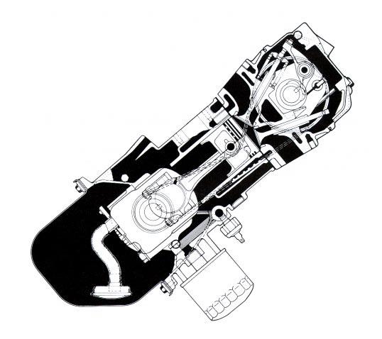
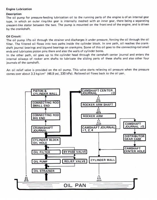
ENGINE LUBRICATION & COOLING SYSTEMS SECTIONLC CONTENTS. ENGINE LUBRICATION SYSTEM...2 Precautions...2
 ENGINE LUBRICATION & COOLING SYSTEMS SECTIONLC CONTENTS ENGINE LUBRICATION SYSTEM...2 Precautions...2 LIQUID GASKET APPLICATION PROCEDURE...2 Preparation...2 SPECIAL SERVICE TOOLS...2 Lubrication Circuit...3
M162 ENGINE MECHANICAL
 SECTION 1B1 M162 ENGINE MECHANICAL CAUTION: Disconnect the negative battery cable before removing or installing any electrical unit or when a tool or equipment could easily come in contact with exposed
13. FUEL SYSTEM/CARBURETOR/
 13 FUEL SYSTEM/CARBURETOR/FUEL PUMP FUEL SYSTEM --------------------------------------------------------- 13-1 SCHEMATIC DRAWING ---------------------------------------------- 13-2 OPERATION OF CARBURETOR
CARBURETOR - HITACHI 2-BBL
 CARBURETOR - HITACHI 2-BBL 1986 Isuzu Trooper II 1986 Hitachi Carburetors HITACHI DCH340, DCR384, DFP340, DFP384 & DHP340 2-BARREL P UP & Trooper II DESCRIPTION Carburetor is a 2-barrel downdraft type
SOHC ENGINE MECHANICAL
 SECTION 1B SOHC ENGINE MECHANICAL CAUTION: Disconnect the negative battery cable before removing or installing any electrical unit or when a tool or equipment could easily come in contact with exposed
7. FUEL SYSTEM ('04 - '05)
") 7. FUEL SYSTEM ('04 - '05) SYSTEM COMPONENTS 7-2 CARBURETOR DISASSEMBLY 7-81 SERVICE INFORMATION 7-3 CARBURETOR ASSEMBLY 7-14 TROUBLESHOOTING 7-4 CARBURETOR INSTALLATION 7-21 AIR CLEANER HOUSING 7-5 PILOT
7. FUEL SYSTEM ('04 - '05) SYSTEM COMPONENTS 7-2 CARBURETOR DISASSEMBLY 7-81 SERVICE INFORMATION 7-3 CARBURETOR ASSEMBLY 7-14 TROUBLESHOOTING 7-4 CARBURETOR INSTALLATION 7-21 AIR CLEANER HOUSING 7-5 PILOT
ENGINE MECHANICAL <3.0L>
 11C-1 GROUP 11C ENGINE MECHANICAL CONTENTS GENERAL DESCRIPTION......... 11C-2 ENGINE DIAGNOSIS............. 11C-2 SPECIAL TOOLS................ 11C-3 ON VEHICLE SERVICE........... 11C-5 DRIVE BELT
EG 18 ENGINE MECHANICAL TIMING BELT EG5EK 01 COMPONENTS FOR REMOVAL AND INSTALLATION
 EG18 ENGINE TIMING BELT COMPONENTS FOR REMOVAL AND INSTALLATION EG5EK01 ENGINE EG19 EG20 ENGINE ENGINE EG21 EG22 ENGINE TIMING BELT REMOVAL EG5G101 1. REMOVE OIL PAN PROTECTOR 2. REMOVE ENGINE UNDER COVER
AN EXPLANATION OF CIRCUITS CARTER YH HORIZONTAL CLIMATIC CONTROL CARBURETER
 AN EXPLANATION OF CIRCUITS CARTER YH HORIZONTAL CLIMATIC CONTROL CARBURETER The Carter Model YH carbureter may be compared with a Carter YF downdraft carbureter with the circuits rearranged to operate
5. FUEL SYSTEM 5-0 FUEL SYSTEM MXU 250R/300R
 5 FUEL SYSTEM 5 SERVICE INFORMATION------------------------------------------------ 5-2 TROUBLESHOOTING----------------------------------------------------- 5-3 FUEL TANK -----------------------------------------------------------------
AJV8 Engine Assembly. AJV8 Engine Assembly
 AJV8 Engine Assembly Contents Cylinder Block Dowels, Plugs and Pipes 2 4 Crankshaft Bearing and Cylinder Bore Dimensions 5 9 Bearing Measuring 6 Engine Dimensions and Codes 6 7 Main Bearing Selection Chart
4. FUEL SYSTEM 4-0 FUEL SYSTEM NEXXON 50
 4 FUEL SYSTEM SERVICE INFORMATION ------------------------------------------------ 4-2 TROUBLESHOOTING----------------------------------------------------- 4-3 AIR CLEANER REMOVAL -----------------------------------------------
COLT 2310, 2510, AND 2712 COM PACT TRACTORS CHAPTER 9 TROUBLESHOOTING AND ANALYSIS
 COLT 2310, 2510, AND 2712 COM PACT TRACTORS CHAPTER 9 TROUBLESHOOTING AND ANALYSIS 9-A-1 UPON RECEIVING ANENGINE FORRE- PAIR. Learn the history of the unit from the customer. While the customer is present
6. Cylinder Block SERVICE PROCEDURE A: REMOVAL 1. RELATED PARTS
 SERVICE PROCEDURE [W6A1] 2-3a A: REMOVAL 1. RELATED PARTS 1) Remove timing belt, camshaft sprockets and related parts. 2) Remove cylinder heads. 3) Remove
MAINTENANCE STANDARDS TABLE
 TABLE 4 MAINTENANCE STANDARDS TABLE Unit: mm [in.] ( Maximum rpm, (no-load) Minimum rpm, (no-load) According to engine specification Adjust governor setting. Compression pressure MPa (kgf/cm 2 ) [psi]
11. CARBURETOR 11-0 CARBURETOR ZX / SCOUT 50
 11 CARBURETOR SERVICE INFORMATION... 11-2 TROUBLESHOOTING... 11-2 THROTTLE VALVE DISASSEMBLY... 11-3 THROTTLE VALVE INSTALLATION... 11-4 CARBURETOR REMOVAL... 11-5 AUTO BYSTARTER... 11-6 FLOAT CHAMBER...
ENGINE <4G9-MPI> Click on the applicable bookmark to selected the required model year
 ENGINE 11B-1 ENGINE CONTENTS GENERAL................................. 2 Outline of Change............................ 2 GENERAL INFORMATION.................. 2 SERVICE SPECIFICATIONS.................
CHASSIS CONTENTS EXTERIOR PARTS 7-1 FRONT WHEEL 7-2 FRONT BRAKE 7-6 HANDLEBARS 7-13 FRONT FORK 7-15 STEERING 7-23 REAR WHEEL 7-26 REAR BRAKE 7-30
 CHASSIS CONTENTS EXTERIOR PARTS 7- FRONT WHEEL 7-2 FRONT BRAKE 7-6 HANDLEBARS 7-3 FRONT FORK 7-5 STEERING 7-23 REAR WHEEL 7-26 REAR BRAKE 7-30 REAR SHOCK ABSORBER 7-32 SWING ARM 7-33 7 7- CHASSIS EXTERIOR
SUPERCHARGER. ON-VEHICLE INSPECTION 1. INSPECT SUPERCHARGER OIL LEVEL HINT: With the engine cold, check the oil level on the dipstick.
 EG45 ONVEHICLE INSPECTION 1. INSPECT OIL LEVEL HINT: With the engine cold, check the oil level on the dipstick. (a) Park the vehicle on a level spot and turn the engine off. (b) 4WD: Remove the LH front
1 of 11 11/6/2016 5:32 AM
 1 of 11 11/6/2016 5:32 AM REMOVAL RELATED PARTS 1) Remove intake manifold. 2) Remove bolt which installs A/C compressor bracket on cylinder head. (With A/C model) 3) Remove camshafts. CYLINDER HEAD 1)
BR-250 / BR-250SS / M2-250 SERVICE MANUAL
 BR-250 / BR-250SS / M2-250 SERVICE MANUAL Manufactured by PGO of Motive Power Industry Co., Ltd 1. INSPECTION/ADJUSTMENT 1 1 INSPECTION/ADJUSTMENT SERVICE INFORMATION -------------------------------------------------
 Page 1 of 75 303-01D Engine - 5.2L 32V Ti-VCT 2016 Mustang Assembly Procedure revision date: 12/15/2016 Special Tool(s) / General Equipment Engine Base Part Number: 6L084 205-142 (T80T-4000-J) Installer,
Engine Does Not Start or Is Hard to Start Cause of Trouble. 1. Open the drain screw, and check Fuel not supplied (1) Fuel tank empty
 Fuel tank empty") 20. Engine Does Not Start or Is Hard to Start 20-1 Engine Output Insufficient 20-2 Poor Performance at Low Speed and Idling 20-3 Poor Performance at High Speed 20-3 Unsatisfactory Operation 20-4 Fuel Gauge
20. Engine Does Not Start or Is Hard to Start 20-1 Engine Output Insufficient 20-2 Poor Performance at Low Speed and Idling 20-3 Poor Performance at High Speed 20-3 Unsatisfactory Operation 20-4 Fuel Gauge
12. CARBURETOR 12-0 CARBURETOR VITALITY 50
 12 12 CARBURETOR SERVICE INFORMATION (2-STROKE)... 12-2 SERVICE INFORMATION (4-STROKE)... 12-3 THROTTLE VALVE (2-STROKE)... 12-5 CARBURETOR (2-STROKE)... 12-7 AIR SCREW ADJUSTMENT (2-STROKE)... 12-13 REED
Timing Belt: Service and Repair
 2000 Hyundai Sonata L4-2.4L Page 1 Timing Belt: Service and Repair REMOVAL 1. Remove the crankshaft pulley, engine coolant pump pulley and drive belt. 2. Remove the timing belt cover. 2000 Hyundai Sonata
ENGINE MECHANICAL <3.0L ENGINE>
 11C-1 GROUP 11C ENGINE MECHANICAL CONTENTS GENERAL DESCRIPTION......... 11C-2 ENGINE DIAGNOSIS............. 11C-3 SPECIAL TOOLS................ 11C-4 ON-VEHICLE SERVICE........... 11C-6 DRIVE
ENGINE CONTENTS ENGINE REMOVAL AND REINSTALLATION 3-1 ENGINE REMOVAL 3-1 ENGINE REINSTALLATION 3-5 ENGINE DISASSEMBLY 3-7 STARTER MOTER 3-7
 ENGINE CONTENTS ENGINE REMOVAL AND REINSTALLATION 3- ENGINE REMOVAL 3- ENGINE REINSTALLATION 3-5 ENGINE DISASSEMBLY 3-7 3 STARTER MOTER 3-7 CYLINDER HEAD COVER 3-8 PISTON 3- MAGNETO COVER 3-3 MAGNETO ROTOR
ENGINE MECHANICAL <4G69>
 11E-1 GROUP 11E ENGINE MECHANICAL CONTENTS SERVICE SPECIFICATIONS....... 11E-2 SEALANTS.................... 11E-2 SPECIAL TOOLS................ 11E-3 ON-VEHICLE SERVICE........... 11E-7 DRIVE BELT
7. CYLINDER HEAD/VALVES
 7 7 7-0 SERVICE INFORMATION...7-1 CYLINDER HEAD DISASSEMBLY...7-7 TROUBLESHOOTING...7-2 CYLINDER HEAD ASSEMBLY...7-8 CAMSHAFT REMOVAL...7-3 CYLINDER HEAD INSTALLATION...7-8 CYLINDER HEAD REMOVAL...7-5
ENGINE MEASUREMENTS ENGINE MEASUREMENTS AND SPECIFICATIONS CYLINDER HEAD. Measure Cylinder Compression. Using Telescoping Gauges and Hole Gauges
 ENGINE MEASUREMENTS AND SPECIFICATIONS Tool List Qty. Required Compression Gauge, 20 kgf/cm²: E-Z-GO Part No. N/A... 1 Compression Gauge Adapter, M14 1.25: E-Z-GO Part No. N/A... 1 Valve Seat Cutter, 45-35
Troubleshooting the Transmission Hydraulic System
 Testing and Adjusting IT28F INTEGRATED TOOLCARRIER POWER TRAIN Testing And Adjusting Introduction Reference: For Specifications with illustrations, refer to SENR5974, IT28F Integrated Toolcarrier Power
26/01/2017 3GR-FSE ENGINE MECHANICAL: ENGINE UNIT: DISASSEMBLY; 2006 MY GS300 [01/ ]
![26/01/2017 3GR-FSE ENGINE MECHANICAL: ENGINE UNIT: DISASSEMBLY; 2006 MY GS300 [01/ ]](/thumbs/85/92233007.jpg "26/01/2017 3GR-FSE ENGINE MECHANICAL: ENGINE UNIT: DISASSEMBLY; 2006 MY GS300 [01/ ]") Last Modified: 8-24-2016 6.6 A Doc ID: RM000000T4X000X Model Year Start: 2006 Model: GS300 Prod Date Range: [01/2005 - ] Title: 3GR-FSE ENGINE MECHANICAL: ENGINE UNIT: DISASSEMBLY; 2006 MY GS300 [01/2005
Last Modified: 8-24-2016 6.6 A Doc ID: RM000000T4X000X Model Year Start: 2006 Model: GS300 Prod Date Range: [01/2005 - ] Title: 3GR-FSE ENGINE MECHANICAL: ENGINE UNIT: DISASSEMBLY; 2006 MY GS300 [01/2005
SUZUKI SQ 416/420/625 M.Y TRANSMISSION SERVICE MANUAL - MANUAL - AUTOMATIC - TRANSFER - DIFFERENTIALS
 SUZUKI SQ 416/420/625 M.Y 1998-2005 TRANSMISSION SERVICE MANUAL - MANUAL - AUTOMATIC - TRANSFER - DIFFERENTIALS WARNING/CAUTION/NOTE IMPORTANT Please read this manual and follow its instructions carefully.
A-PDF Split DEMO : Purchase from to remove the watermark
 5-18 FUEL AND LUBRICATION SYSTEM A-PDF Split DEMO : Purchase from www.a-pdf.com to remove the watermark Use a % size drill bit with a drill-stop to remove the pilot screw plug. Set the drill-stop 6 mm
ATV 90 UTILITY GREEN (A2006KUB2BUSG) Page 1 of 60 AIR INTAKE ASSEMBLY
 Page 1 of 60 AIR INTAKE ASSEMBLY") 2006 ATV 90 UTILITY GREEN (A2006KUB2BUSG) Page 1 of 60 AIR INTAKE ASSEMBLY 2006 ATV 90 UTILITY GREEN (A2006KUB2BUSG) Page 2 of 60 AIR INTAKE ASSEMBLY Ref # Part Number Qty S/P/F Description 1 3303-005
2006 ATV 90 UTILITY GREEN (A2006KUB2BUSG) Page 1 of 60 AIR INTAKE ASSEMBLY 2006 ATV 90 UTILITY GREEN (A2006KUB2BUSG) Page 2 of 60 AIR INTAKE ASSEMBLY Ref # Part Number Qty S/P/F Description 1 3303-005
HKS 700E. Service Manual June Ver. 2.04
 HKS 700E Service Manual 009 June Ver..04 HKS CO.,LTD 78 KITAYAMA FUJINOMIYA SHIZUOKA JAPAN 48-09 TEL +8(0)544-54-78 FAX +8(0)544-54-40 hks_aviation@hks-power.co.jp http://www.hks-power.co.jp/hks_aviation/
5. Cylinder Block. 2-3b [W5A1] SERVICE PROCEDURE A: REMOVAL 1. RELATED PARTS
![5. Cylinder Block. 2-3b [W5A1] SERVICE PROCEDURE A: REMOVAL 1. RELATED PARTS](/thumbs/82/85637729.jpg "5. Cylinder Block. 2-3b [W5A1] SERVICE PROCEDURE A: REMOVAL 1. RELATED PARTS") 2-3b [W5A1] SERVICE PROCEDURE A: REMOVAL 1. RELATED PARTS 1) Remove timing belt, camshaft sprockets and related parts. S2M0303 48 SERVICE PROCEDURE [W5A1] 2-3b 2) Remove rocker cover,
2-3b [W5A1] SERVICE PROCEDURE A: REMOVAL 1. RELATED PARTS 1) Remove timing belt, camshaft sprockets and related parts. S2M0303 48 SERVICE PROCEDURE [W5A1] 2-3b 2) Remove rocker cover,
ATV 90 UTILITY CALIFORNIA GREEN (A2008KUB2BCAG) Page 1 of 58 AIR INTAKE ASSEMBLY
 Page 1 of 58 AIR INTAKE ASSEMBLY") 2008 ATV 90 UTILITY CALIFORNIA GREEN (A2008KUB2BCAG) Page 1 of 58 AIR INTAKE ASSEMBLY 2008 ATV 90 UTILITY CALIFORNIA GREEN (A2008KUB2BCAG) Page 2 of 58 AIR INTAKE ASSEMBLY Ref # Part Number Qty S/P/F Description
2008 ATV 90 UTILITY CALIFORNIA GREEN (A2008KUB2BCAG) Page 1 of 58 AIR INTAKE ASSEMBLY 2008 ATV 90 UTILITY CALIFORNIA GREEN (A2008KUB2BCAG) Page 2 of 58 AIR INTAKE ASSEMBLY Ref # Part Number Qty S/P/F Description
FU-1 FUEL SYSTEM. Page PRECAUTIONS... TROUBLESHOOTING... ON-VEHICLE INSPECTION...
 FU-1 FUEL SYSTEM PRECAUTIONS... TROUBLESHOOTING... ON-VEHICLE INSPECTION... CARBURETOR FUEL PUMP... Page FU-2 FU-2 FU-3 FU-4 FU-28 FU-2 FUEL SYSTEM - Precautions, Troubleshooting PRECAUTIONS 1. Before
FORD V8 ENGINES 209. the treated area, the block is cracked and should be replaced.
 FORD V8 ENGINES 209 Cylinder block Core plug Strike here with hammer Drift 8 the treated area, the block is cracked and should be replaced. 3. Check flatness of the cylinder block deck. Place an accurate
DVX 90 MODEL NUMBER A2008KSB2BUSD (BLACK-RED) MODEL NUMBER A2008KSB2BUSE (BLACK-CAT GREEN) MORE TO GO ON. TM
 MODEL NUMBER A2008KSB2BUSE (BLACK-CAT GREEN) MORE TO GO ON. TM") 2008 DVX 90 Illustrated Parts Manual MODEL NUMBER A2008KSB2BUSD (BLACK-RED) MODEL NUMBER A2008KSB2BUSE (BLACK-CAT GREEN) MORE TO GO ON. TM TABLE OF CONTENTS Black-Red (Model No. A2008KSB2BUSD) Black-Cat
2008 DVX 90 Illustrated Parts Manual MODEL NUMBER A2008KSB2BUSD (BLACK-RED) MODEL NUMBER A2008KSB2BUSE (BLACK-CAT GREEN) MORE TO GO ON. TM TABLE OF CONTENTS Black-Red (Model No. A2008KSB2BUSD) Black-Cat
Remove Air Cleaner Cover and. Filter
 Remove Air Cleaner Cover and Inspect paper filter for tears Foam pre-cleaner is washable if equipped Replace if necessary Filter Remove Trim Panel Pull throttle lever knob off Remove 3, 8mm screws Remove
World Formula TECH MANUAL
 World Formula TECH MANUAL Section 1 General Rules 1. Only stock Briggs & Stratton World Formula Model # 124435-8101 will be used in this class except as provided in this Tech manual. All parts will be
Fig. 6: Assembling Piston & Rod. NOTE: Notch must face forward Toyota Starlet CRANKSHAFT MAIN BEARINGS
 connecting rods are marked for reassembly. 3. Thoroughly clean and inspect all components. Coat pin with engine oil and heat piston to 158-176 F (70-80 C). Pin should push fit with thumb pressure through
Engine Electrical System
 Engine Electrical System 3 Foreword This manual has been prepared by experts and specialists of,engineering Department of Saipa Yadak Company to be used as a guide by the repairers of electrical systems.we
ENGINE MECHANICAL EM SECTION CONTENTS
 ENGINE MECHANICAL EM SECTION CONTENTS INTAKE MANIFOLD...EM-2 Component Parts Location...EM-2 Removal and Installation...EM-3 Inspection...EM-3 EXHAUST MANIFOLD...EM-4 Component Parts Location...EM-4 Removal
5. Cylinder Head. 2-3a [W5A1] SERVICE PROCEDURE A: REMOVAL 1. RELATED PARTS 2. CYLINDER HEAD
![5. Cylinder Head. 2-3a [W5A1] SERVICE PROCEDURE A: REMOVAL 1. RELATED PARTS 2. CYLINDER HEAD](/thumbs/89/100992456.jpg "5. Cylinder Head. 2-3a [W5A1] SERVICE PROCEDURE A: REMOVAL 1. RELATED PARTS 2. CYLINDER HEAD") 2-3a [W5A1] SERVICE PROCEDURE A: REMOVAL 1. RELATED PARTS 1) Release fuel pressure. 2) Drain engine coolant. 3) Remove V-belt(s). 4) Remove generator and bracket.
2-3a [W5A1] SERVICE PROCEDURE A: REMOVAL 1. RELATED PARTS 1) Release fuel pressure. 2) Drain engine coolant. 3) Remove V-belt(s). 4) Remove generator and bracket.
ENGINE REMOVAL AND REINSTALLATION 3-1 ENGINE REMOVAL 3-1 ENGINE REINSTALLATION
 ENGINE CONTENTS ENGINE REMOVAL AND REINSTALLATION 3-1 ENGINE REMOVAL 3-1 ENGINE REINSTALLATION 3-5 ENGINE DISASSEMBLY 3-6 ENGINE COMPONENTS INSPECTION AND SERVICING 3-15 BEARINGS 3-15 OIL SEALS 3-15 CRANKSHAFT
INDEX INTRODUCTION. Reference No L-01 REVISED:
 12-21L-01 1 1 INTRODUCTION We are constantly working on technical improvement of our products. For this reason, technical data, equipment and design are subject to change without notice. All specifications
ENGINE OVERHAUL <2.4L ENGINE>
 11B-1 GROUP 11B ENGINE OVERHAUL CONTENTS SPECIAL TOOLS 11B-2 GENERATOR AND IGNITION SYSTEM 11B-6 REMOVAL AND INSTALLATION 11B-6 EXHAUST MANIFOLD 11B-9 REMOVAL AND INSTALLATION 11B-9 TIMING
Bthird, or power stroke by the expanding gases. As the
 third, or power stroke by the expanding gases. As the piston reaches DC it enters the fourth cycle. The exhaust valve opens and the piston rises forcing burned gases from the combustion chamber in what
2.0L 4-CYL & 2.0L 4-CYL TURBO - VIN [S]
![2.0L 4-CYL & 2.0L 4-CYL TURBO - VIN [S]](/thumbs/81/82864711.jpg "2.0L 4-CYL & 2.0L 4-CYL TURBO - VIN [S]") 2.0L 4-CYL & 2.0L 4-CYL TURBO - VIN [S] 1988 Toyota Celica 1988 TOYOTA ENGINES 2.0L & 2.0L Turbo 4-Cylinder Celica * PLEASE READ THIS FIRST * NOTE: For engine repair procedures not covered in this article,
2.0L 4-CYL & 2.0L 4-CYL TURBO - VIN [S] 1988 Toyota Celica 1988 TOYOTA ENGINES 2.0L & 2.0L Turbo 4-Cylinder Celica * PLEASE READ THIS FIRST * NOTE: For engine repair procedures not covered in this article,
TILLOTSON LTD., CLASH INDUSTRIAL ESTATE, TRALEE, CO. KERRY, IRELAND PHONE: FAX:
 TILLOTSON LTD., CLASH INDUSTRIAL ESTATE, TRALEE, CO. KERRY, IRELAND PHONE: +353 66 7121911 FAX: +353 66 7124503 e-mail: sales@tillotson.ie SERIES SERVICE MANUAL INTRODUCTION The gasoline engine industry
BOTTOM END SERVICE TOOLS SERVICE PRODUCTS ENGINE, CVT AND GEARBOX Subsection 10 (BOTTOM END)
") BOTTOM END SERVICE TOOLS Description Part Number Page CRANKCASE SUPPORT MAG/PTO... 529 036 031... 151 CRANKSHAFT LOCKING BOLT... 529 035 617... 154 DRIVE SHAFT OIL SEAL INSTALLER... 529 036 028... 143
BOTTOM END SERVICE TOOLS Description Part Number Page CRANKCASE SUPPORT MAG/PTO... 529 036 031... 151 CRANKSHAFT LOCKING BOLT... 529 035 617... 154 DRIVE SHAFT OIL SEAL INSTALLER... 529 036 028... 143
CLEANING, INSPECTION AND REPAIR. Valve Spring Compressor (Part No. HD-34736B) Figure Compressing Valve Springs
 Figure Compressing Valve Springs") b0134x3x 5694 8 7 12 10 1 6 13 11 Valve Spring Compressor (Part No. HD-34736B) 9 Figure 3-11. Compressing Valve Springs 5 14 4 3 2 15 2767a 1. Right crankcase half 2. Pin (2) 3. O-ring (2) 4. Plate 5.
b0134x3x 5694 8 7 12 10 1 6 13 11 Valve Spring Compressor (Part No. HD-34736B) 9 Figure 3-11. Compressing Valve Springs 5 14 4 3 2 15 2767a 1. Right crankcase half 2. Pin (2) 3. O-ring (2) 4. Plate 5.
PERFORMER RPM Camshaft/Lifters/Lube Kit CATALOG #7102 MODEL: c.i.d. Chevrolet V8, 1957 & later
 PERFORMER RPM Camshaft/Lifters/Lube Kit CATALOG #7102 MODEL: 262-400 c.i.d. Chevrolet V8, 1957 & later CAMSHAFT: Edelbrock Performer RPM camshafts are ground specifically for use with the corresponding
1989 BMW 635CSi. 3.5L 6-CYL Engine - 3.5L 6-Cylinder
 Fig. 3: Rocker Arm Assembly Courtesy of BMW OF NORTH AMERICA, INC. VALVE SPRINGS NOTE: Install springs with paint stripe (tight coil end) against head. Inspection Check spring free length. Check spring
SERVICE DATA CHAIN SAW ECHO: CS-500ES STAGE MODEL. (Serial number : and after) CONTENTS INTRODUCTION
 CONTENTS INTRODUCTION") 01-50D-01 1 0 SERVICE DATA CHAIN SAW ECHO: STAGE MODEL (Serial number : 37000001 and after) INTRODUCTION We are constantly working on technical improvement of our products. For this reason, technical data,
01-50D-01 1 0 SERVICE DATA CHAIN SAW ECHO: STAGE MODEL (Serial number : 37000001 and after) INTRODUCTION We are constantly working on technical improvement of our products. For this reason, technical data,
5-2 FUEL SYSTEM AND THROTTLE BODY FUEL SYSTEM FUEL DELIVERY SYSTEM The fuel delivery system consists of the fuel tank, fuel pump, fuel filters, fuel f
 FUEL SYSTEM AND THROTTLE BODY 5-1 FUEL SYSTEM AND THROTTLE BODY I CONTENTS FUEL SYSTEM 5-2 FUEL DELIVERY SYSTEM 5-2 FUEL PUMP 5-3 FUEL PRESSURE REGULATOR 5-4 FUEL INJECTOR 5-4 FUEL PUMP CONTROL SYSTEM
GROUP 11C 11C-1 CONTENTS GENERAL DESCRIPTION... 11C-2 ENGINE DIAGNOSIS... 11C-2 CRANKSHAFT FRONT OIL SEAL... 11C-30 SPECIAL TOOLS...
 11C-1 GROUP 11C CONTENTS GENERAL DESCRIPTION 11C-2 ENGINE DIAGNOSIS 11C-2 SPECIAL TOOLS 11C-3 ON VEHICLE SERVICE 11C-5 DRIVE BELT TENSION CHECK AND ADJUSTMENT 11C-5 IGNITION TIMING CHECK 11C-5 IDLE MIXTURE