Owner s Manual and Installation Guide
|
|
|
- Maurice Morrison
- 5 years ago
- Views:
Transcription


1 Owner s Manual and Installation Guide The proven leader in household leak protection: WaterCop is there when you re not.
2 Table of Contents System Description... 2 System Components... 2 General Safety Information... 2 How the System Works... 4 Selection of WaterCop Installation Sites... 4 Placement of Wireless Sensors... 5 Leak Sensor Battery Life... 5 Operating the WaterCop Classic System... 6 WaterCop Specifications... 6 FCC Information... 6 Additional Components Available for Your WaterCop Classic System Single and Dual Probe WaterCop Leak Sensors... 7 Low Temperature Sensor... 7 Water Control Wall Switch... 7 AC Power Adapter... 7 WaterCop /Wall Switch Interconnect Cable... 7 Installation Guide Pre-Installation Testing of WaterCop Manually Test the Valve... 8 Manually Test the Leak Sensors... 8 Troubleshooting... 8 Installation of Leak Sensor... 9 Installation Procedure Review Location and Type of Main Supply Line... 9 Additional Part Requirements Compression Fittings Solder Fittings Electrical Connection Warnings and Precautions Changing Digital Codes Changing the Receiver Code Changing the Transmitter Code System Description The WaterCop Classic System is designed to detect leaks in your plumbing system at predetermined locations, and automatically shut off the water supply to help effectively reduce the chance of major water damage associated with a leak. System Components The WaterCop Classic System is composed of two basic parts: A motorized ball valve that houses a wireless radio receiver which automatically turns off your water supply when any leak sensor detects water or low temperature sensor detects potential freezing. Leak sensors, which detect water from a leak or overflow, house a wireless radio transmitter that sends a signal to the WaterCop to turn off your water supply. CAUTION! It is strongly recommended that eye protection be worn while servicing the system. Failure to do so could result in personal injury. DO NOT USE EXTENSION CORDS. KEEP FINGERS AND OBJECTS AWAY FROM THE VALVE. GENERAL SAFETY INFORMATION Do not apply electrical power to the unit unless the unit is fully assembled. Failure to do so could result in personal injury and/or damage to the unit. Disconnect power source before working on or servicing the unit. Failure to do so could result in personal injury. WaterCop Interface Connections Emergency Procedures
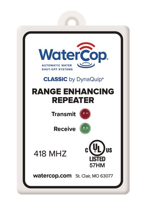
3 WaterCop Classic System WaterCop Classic Actuator Brass, Lead-Free Valve (sold separately) Transmitter Range Enhancing Repeater RANGE ENHANCING REPEATER Transmit Receive Probe DynaQuip Controls, Inc. St. Clair, MO MHZ watercop.com St. Clair, MO DynaQuip Controls, Inc. St. Clair, MO 3
4 How the System Works Leak sensors constantly monitor their selected areas for accumulating moisture. When a leak is detected, a sensor will send a radio frequency signal to the WaterCop unit instructing it to shut off the water supply to the home. The WaterCop valve will remain closed until it is manually reset. The leak sensors are a battery powered device enabling it to be located anywhere a leak is likely to occur, or where water might cause damage. The WaterCop requires household electrical power (120 VAC outlet) and will not operate during a power outage unless receiving auxiliary power from a backup device such as an uninterruptible power supply unit (UPS). Additionally, the use of a certified surge protection device is highly recommended. The WaterCop requires household electrical power, and the provided power adapter must be plugged into a 120 VAC power source. Do not use an extension cord. As with all sensitive electric equipment, the use of surge protection is highly recommended. The shut-off valve must be installed indoors: In the main water line; In place of or just downstream from the main water shut-off valve; In a dry location; Where it is accessible for checking and resetting the valve and for resetting the radio receiver code, if necessary; Where the case is protected from use as a step or from other excessive loads. Local electrical and plumbing codes should be consulted to ensure that the installation is in complete compliance. (See Installation section for details.) Notice: WaterCop should be installed downstream of existing shut-off valves and pressure reducers. Install 18" downstream from existing indoor water meters to allow for future meter maintenance. Selection of WaterCop Installation Sites The WaterCop valve should be installed in the main water line just downstream from the main shut-off valve in your home. The front control panel of the WaterCop should be easily visible in order to see what position the valve is in (open/closed). It should also be easily accessible for resetting after a leak has been detected and the water supply has been shut off. While the WaterCop is completely supported by the piping in your plumbing system when it is installed, placement of the valve should ensure that the housing is protected from use as a step or from other excessive loads. 4
5 Placement of Wireless Sensors Each WaterCop Classic System can support an unlimited number of wireless leak sensors. Additional sensors may be added at any time. A sensor consists of a transmitter (a rectangular box) and a sensor probe (a small disc at the end of the wire, with two short gold prongs protruding from one side). Leak sensors should be placed in locations where leaks are most likely to occur. Suggested Locations Washing Machines Toilets Dishwashers Ice Makers/Refrigerators Kitchen Sinks Automatic Humidifiers Bathroom Sinks Water Heaters Pipes that are prone to freezing (freeze sensors are also available) The transmitter in the leak sensors and the receiver in the WaterCop communicate by radio frequency. The smaller the distance between them, the stronger the signal will be. The maximum transmission distance is somewhat dependent upon the building layout and type of construction, but will be in the 150'-200' range. The transmitter (attached to the sensor) must be kept dry. It is NOT splash proof. Sensors should never be placed outdoors. The sensor probe detects the water from a leak and is completely waterproof. Sensor probes should be placed on the floor or in areas where water would tend to accumulate rapidly in common leak or overflow situations. Make sure that any water from a leak will drain toward the sensor probe, not away from it. Avoid high traffic areas where the cord or sensor could be stepped on or kicked and where children or pets may disturb it. The sensor probe should be placed FLAT on the floor so water can be detected as soon as it begins to accumulate. The sensor probe should be secured to the floor. Do not use hook and loop fasteners to secure sensor to floor as this will raise the probe too high above the floor. To avoid damage to transmitters and to provide for the strongest signal possible, the transmitter portion of the leak sensor should be mounted in a convenient location (on the wall, in a cabinet, closet, etc.) two to three feet above the floor. (See Installation section for details on sensor installation.) Leak Sensor Battery Life Fresh, high quality AA alkaline batteries are recommended. Assuming the sensor has not detected and transmitted a leak condition (standby mode); high quality AA alkaline batteries should last between three to five years. Sensors will sound an audible chirp sound when batteries are low. Replace batteries when low or during periodic maintenance to ensure proper power and function. Re-test each unit in its regular location (see Installation Manual). 5
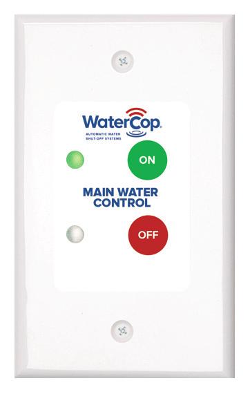
6 Operating the WaterCop Classic System The normal position of the valve is open to allow full flow throughout the plumbing system. WaterCop is a full port ball valve which does not restrict the flow capacity of your plumbing system. The indicator lights on the face of the WaterCop will show the position of the valve. If the valve is in the closed position (the red light will be lit), press OPEN and the valve will move to the open position (green indicator will light). When water comes in direct contact with a leak sensor, an RF (radio frequency) signal is transmitted to the WaterCop and the valve closes, turning off the water source to protect the building from additional damage. The red indicator light will signal that the valve is now in the closed position, and that you need to check all areas where you have placed a sensor to determine what plumbing product caused the system to activate. The valve will remain closed until the unit is manually reset on the WaterCop panel. After the plumbing problem is fixed, reset the WaterCop by pressing OPEN (green circle) on the face of the WaterCop. Valve will open and green indicator will be lit. (See illustration.) Note: If major repairs are needed to correct the plumbing system, it is recommended that the manual shut-off valve upstream of the WaterCop also be closed during the repairs. Close the main water shut-off valve and unplug the WaterCop before making repairs on the plumbing system. Note: In case of a power failure, the WaterCop cannot operate. If the power is out, you will need to use the manual shut-off valve to turn the water off in case of an emergency. When power is restored, the WaterCop will remain in its last known position indicated by the red or green lights on the face of the unit. WaterCop Specifications Actuator Max. working pressure 125 psig Ambient temperature 35 to 105 F Enclosure Polycarbonate Voltage 12 VDC plus 120 VAC adapter Current 0.85 Amps (Full Load) Accessories Sensor Signal Repeater 120 VAC 47mA Sensors 3 VDC (2AA Batteries) 10mA Valve Valve Full-Port, Lead-Free Brass, NPT Valve seals RTFE (Reinforced Teflon ) Flow Data Valve Size Cv = Gpm flow at 1 psi pressure drop ½" NPT 19 1" NPT 52 ¾" NPT 34 1¼" NPT 77 For cold water applications FCC Information This equipment has been tested and found to comply with the limits for a Class B digital device, pursuant to part 15 of the FCC Rules. These limits are designed to provide reasonable protection against harmful interference in a residential installation. This equipment generates, uses, and can radiate radio frequency energy and if not installed and used in accordance with the instructions, may cause harmful interference to radio communications. However, there is no guarantee that interference will not occur in a particular installation. If this equipment does cause harmful interference to radio or television reception, which can be determined by turning the equipment off and on, the user is encouraged to try to correct the interference by one or more of the following measures: Reorient or relocate the receiver; Increase the separation between the equipment and receiver; Connect the equipment into an outlet on a circuit different from that to which the receiver is connected; Consult the dealer for help. Operation is subject to the following two conditions: 1. this device may not cause interference; 2. this device must accept any interference, including interference that may cause undesired operation of the device. CAUTION: The user is cautioned that changes and modification made to the equipment without the approval of the manufacturer could void the user s authority to operate this equipment. 6
7 Additional Components Available for Your WaterCop Classic System Single and Dual Probe WaterCop Leak Sensors WCDFS1 (single probe) and WCDFS2 (dual probe) Battery or AC (optional) powered Transmits wireless signal to valve when moisture is detected Unlimited number can be used, placed anywhere 10' sensor cord, white Low Temperature Sensor WCDFST Monitors temperature of pipes prone to freezing Sends wireless signal to turn off water if low temperature detected 10' cord with clip to attach to pipe Leak sensor with probe Water Control Wall Switch RS100 Proactively turn water on or off from convenient location Lighted display to valve position (on or off) Requires category 5E cabling connection to valve (see below) AC Power Adapter WPA For WCDFS1, WCDFS2, and WCDFST sensors Eliminates the need for AA batteries WaterCop / Wall Switch Interconnect Cable CBL50 (50') and CBL100 (100') Required to connect WaterCop valve with Water Control Wall Switch RJ45 molded connections for easy installation and durability Installation Guide IMPORTANT! Adherence to all local and municipal building, plumbing and electrical codes as they pertain to the installation of the WaterCop Classic System is of utmost importance. Codes in some areas may require that a licensed plumber be employed to do the installation, or that the proper permits be obtained prior to any installation. Even if local codes do not require a licensed plumber to do the installation, it is necessary that the installer has a professional level of competence in both plumbing and electrical skills to perform the installation. These instructions assume this level of knowledge and skill. If in doubt, use a licensed professional. CAUTION! The valve closes with great force. It could cut off a finger. Keep fingers and other items out of the valve when testing. WARNING! The WaterCop case is NOT EXPLOSION PROOF. The shut-off valve must NOT be installed where it could ignite flammable vapors or explosive mixtures. To reduce risk of electrical shock, fire, or damage to property or WaterCop : Do not use extension cords. Use of extension cords can cause fires or electric shock. Install WaterCop within 20 feet of an outlet or, install an outlet near the WaterCop. Comply with all local codes. Before opening case, unplug power cord. When case is open, it is possible to contact electrified components. Always unplug the power cord before opening the unit. Wear eye protection for plumbing and electrical work. NOTICE: WaterCop should be installed downstream of existing shut-off valves and pressure reducers. Install 18" downstream from existing indoor water meters to allow for future meter maintenance. 7
8 Manually Testing the Valve and Wireless Sensors Manually Test the Valve To test your WaterCop Classic System, gently pull the safety plugs out from each end of the valve. Check the position of the valve by looking in either threaded end. In the open position, you will be able to see through the valve; in the closed position only the shiny surface of the ball will be visible. Place the base of the housing on a sturdy surface, as close as feasibly possible to the location where it will be permanently installed. Plug the WaterCop power cord into a nearby 120 VAC outlet. The valve position indicator lights should now correspond to the actual position you noticed: Green = Open, Red = Closed. Grasp both sides of the housing (not the valve) with the valve pointing away from you for safety. Being very careful not to have your fingers or other objects near the valve openings, press the colored circle just below the unlit indicator light. You will hear the motor change the valve position. Again, look into the threaded end of the valve to verify that the valve has changed position. If it appears that the valve has not turned from one position to the other, DO NOT try to reposition the valve yourself by inserting any tool or fingers into the valve. Operate the valve several more times from open to close, checking each time for proper positioning. If you are experiencing trouble getting the valve to open and shut, call Manually Test the Leak Sensors Leak and Temperature sensors require power to operate. Use either fresh AA alkaline batteries (not included) and/or a WaterCop AC Adapter (sold separately) to power. If both are used, batteries will provide back-up power in the event AC power is lost. Rechargeable batteries are not recommended. To install batteries, remove the battery cover located on the back of the sensor and install batteries in accordance with the (+ and -) placement guide. Reinstall the back plate. Follow suggestions found in the section titled Placement of Leak Sensors for recommendations where sensors should be placed. Locate a wall near the area you choose to monitor. Avoid high traffic areas where cord or sensor could be stepped on or kicked. Mount transmitter at a convenient location on the wall, two to three feet above the floor. This will help avoid damage to the sensor and provide a strong signal. Use provided mounting hardware. 1. Following all safety precautions, make sure that the WaterCop is plugged in and the valve is in the OPEN position. Leave the WaterCop near your main water line, on a sturdy surface. It is important that anyone who will be near the valve is aware of the safety precautions, and does not insert any object into the valve, or handle the valve during the test. 2. At one of the locations you have chosen to monitor, drop the sensor probe (not the mounted transmitter) into a cup of water. Hold until you hear the sensor transmit a signal to the WaterCop (about 5 seconds) and beep. This test simulates a leak, and lets you check for interference between the sensor and the WaterCop. 3. Take the sensor out of the water and carefully dry off the sensor and prongs. It should stop beeping. 4. Go back to your WaterCop and verify that the valve has closed (the red indicator light will be lit). 5. Keeping all objects away from the valve, reset the WaterCop by pushing the green circle below the OPEN text. 6. Repeat steps 2 through 5 until you have tested each sensor directly in the locations you wish to monitor. Troubleshooting If the wireless sensor does not close the valve, check that the sensor has power and batteries and/or AC adapter is installed correctly. Repeat test. If the batteries have power and the wireless sensor still does not make the valve close, physically remove it from its installed location and place it next to the WaterCop unit. Repeat test. If the sensor operates properly when it is closer to the Water Control Panel, but not when it is installed at its remote location, try moving the sensor to a different position or try a different wireless sensor. Some possible causes of signal reduction are steel construction, foil backed insulation or other large metallic barriers. You may also use a range enhancing repeater (WPR sold separately) to extend the effective range of the wireless signals. If the unit still does not function properly, check the digital code settings (see instructions for changing digital codes). If the code matches the code on the WaterCop valve, and it still does not function properly, replace the sensor. 8
9 Installation of Leak Sensor Once testing is complete, finish installation of the leak sensors by unwinding the cord and placing the sensor probe on the floor at the lowest point (where water would naturally collect) in the area to be monitored. Be sure that the sensor is placed FLAT on the floor so water can be detected as soon as it begins to accumulate. The sensor should be secured to the floor, taking care that the metal probes are not covered. Verify that the transmitter and wire are clear of doors, drawers, sharp edges, or other hazards that may cause damage. Unplug the WaterCop after the testing is complete. The WaterCop can now be installed. Prior to installation, read all warnings and precautions carefully. Water level Probe Sensor placed at a low spot in the path of water flow where it will make contact with sensor. Installation Procedure Check the contents of the carton with the products listed on the carton label. The shipping package should contain the following: 1 each WaterCop with power adapter (20' cord) 1 each Owner s Manual/Installation Guide Note: The package may contain sensors if purchased as part of kit. Read Operating Instructions before any installation is attempted. All sections of this Owner s Manual/ Installation Guide should be read and completely understood. Review Location and Type of Main Supply Line The main supply line should enter the house in either the basement or a crawl space beneath the first floor. The water main shut-off valve is usually located near where the line comes through the basement wall or just after the water line enters the living area from the crawl space. In apartments, townhouses, and manufactured housing constructions the water main shut-off valve can usually be found in close proximity to the water heater installation. The WaterCop valve should be installed in the main water line just downstream from the main shut-off valve in your home. The water supply must be shut off prior to installation of the WaterCop. Choose a dry location to install the WaterCop. The front control panel should be easily visible in order to see what position the valve is in (open/closed) and accessible for resetting after a leak has been detected and corrected, and for checking and resetting the radio receiver code if necessary. Place the valve where the housing is protected from use as a step or other excessive loads. The shut-off valve must be installed: In the main water line; Just downstream from the main water shut-off valve; In a dry location (indoors only); Where it is accessible for checking and resetting the valve and for resetting the radio receiver code, if necessary; and Where the case is protected from use as a step or other excessive loads. CAUTION: Never use the housing for leverage when mounting this unit or tightening fittings. Use a wrench on the valve flats that are provided. CAUTION: High heat from soldering or brazing can damage valve seats or motor housing. Proper precautions should be taken to prevent damage from heat when installing the unit. Remove plastic housing before soldering valve in place. WARNING: Do not use on fire sprinkler systems. 9
10 Additional Part Requirements Installation of the WaterCop will require additional parts. When the main supply line is cut to accommodate the WaterCop, new fittings will be needed to connect the ends of the piping to the WaterCop valve. The type of connecting fittings to use will be determined by the type of existing piping, local plumbing codes, and industry standard practices. The most common material for water supply lines is copper. If the WaterCop is to be installed in a copper line, you still have a choice of fittings and methods of installation. Compression Fittings The unit can be installed with compression fittings using common household tools and basic mechanical ability. You will need: two fittings (male pipe thread x compression) available at most local hardware or plumbing supply stores; Teflon tape or thread sealant; tubing cutter; ruler; pencil or marker; two large adjustable wrenches Measure the outside diameter of the copper tube and note the valve size to be sure you purchase the proper size fittings for the job. 1. Remove nuts and sleeves from compression fittings and install the fittings into each end of the valve using Teflon tape or other thread sealant to ensure a watertight seal. Hold one wrench on flats of valve body and use the other to tighten fittings. 2. Measure the distance from end to end of valve assembly. For ½" tube (5/8" outside diameter) subtract ½", for ¾" tube (7/8" outside diameter) subtract ¾" from your measurement. This is the length of the section of tubing to be cut out of the existing line. The piece of existing tubing to be cut out is shorter than the measured length so that tube ends extend into the compression fittings. 3. Select the location for the WaterCop. Be sure to consider that you will need access to the front panel of the control unit. After cutting the section of tube out of the line, you will need to shift the tube ends to be able to fit the unit into place. Make sure you will have access and room to adjust before you cut the tube. 4. Mark the tube in the location you have selected. Double check the length and location you marked. 5. Turn water off and drain the system. 6. Use tube cutter to cut copper tube at the locations you marked. Careful, there will probably still be some water in the line. 7. Remove any burrs from the tube ends and clean ends. 8. Install compression nuts and sleeves to each tube end. 9. Shift tube ends to install WaterCop valve in line. 10. Position the unit and tighten compression nuts. Hold the fitting with one wrench while tightening the nut with the other. Tighten both nuts. 11. Plug unit into a proper power source and turn valve to open position (OPEN button/green light). 12. Unplug unit, turn water back on and carefully check for leaks. 13. Tighten fittings if needed to stop any leaks. 14. Plug unit back into power source. Installation is complete. Solder Fittings An alternative method is to solder the unit into the water line. This method requires a considerably higher skill level to accomplish the installation properly and safely. If you are not skilled in this area, it is strongly recommended that you contact a professional plumber to do this type of installation. Electrical Connections The WaterCop is supplied with a power adapter (20' cord) to be plugged into a 120 VAC power source. It is recommended that the WaterCop not be plugged into an extension cord. Review Specification current and power requirements as not to overload the circuit supplying power. As with all valuable electronic items; we recommend plugging the WaterCop Actuator into a surge protector. 10
11 Warnings and Precautions WARNING! The motorized drive unit case is not capable of supporting any loads. Do no attempt to use the unit as a step. This will cause damage to the unit and could cause personal injury. Do not store highly flammable items such as oily rags or other combustibles near your WaterCop. 4. Some WaterCop receivers may have 6 dip switches. To match codes between 6 and 8 dip switch units, set switches 1-6 exactly the same on both units. Switches 7 and 8 must remain in the on or up position. 5. Reinstall cover. Carefully tuck wires completely into case and hold cover in position while tightening screws. 6. Reconnect power by plugging the power cord into power receptacle. CAUTION! It is recommended that eye protection be worn while installing or servicing the system. Failure to do so could result in personal injury. CAUTION! Do not use the case as leverage when mounting this unit or tightening fittings. Apply wrench to flats on the valve body to tighten fittings. Changing Digital Codes Codes on all control units and transmitters are set at the factory and should not require alteration. If you use other wireless products in your home (garage door openers, etc.), there is a slight chance of interference with the signal. The following instructions will aid in resetting the code. Important Note: All transmitters and the control unit must have the same code setting! Changing the Receiver Code Disconnect power to receiver unit by unplugging power cord. 1. Remove cover using the 4 screws located in the corners of the cover. 2. Locate code switch block (see illustration page 12). Switches are numbered 1 through Arrange the switches in any combination (on or off position). Write down the code combination you selected. Example: 1-on, 2-off, 3-off, 4-on, 5-off, 6-on, 7-off, and 8-off. Changing the Transmitter Code 1. Remove transmitter cover. 2. Locate code switch block. Switches are numbered 1 through Arrange the switches in the exact combination as the code that you set in the receiver. It is important that the same exact code be set in the receiver and all transmitters. If the codes differ, the unit will not function properly. 4. Some WaterCop transmitters may have 6 dip switches. To match codes between 6 and 8 dip switch units, set switches 1-6 exactly the same on both units. Switches 7 and 8 must remain in the on or up position. 5. Test each transmitter to ensure that the unit is functioning properly. 6. If not, verify that all codes are set the same. When all transmitters are functioning properly, your WaterCop Classic System is on duty to help protect your home from damage due to plumbing leaks. 11
12 WaterCop Interface Connections Contacts 5, 6 and 7 are used to control the valve position from a remote location. The most common is your home security system control panel. This is done by wiring these contacts to a control switch on the panel. The diagram below shows typical installation options. This control can be a relay, push buttons or toggle type switch. This control needs to be a momentary switch, which means that the control switch stays made or on for a short period of time (1 to 3 seconds) and then returns to a neutral position. Contacts 2, 3 and 4 are used to signal a remote device as to the position of the valve. This is done by connecting a low voltage circuit with indicator lights to these contacts. The diagram shows a typical installation. When the valve is in the closed position, contacts 2 and 3 will be made completing the circuit and lighting the indicator light, showing that the valve is in the normal open position. When the valve is in the open position, contacts 3 and 4 will be made completing the circuit and lighting the indicator light, showing that the valve is closed. Emergency Procedures In the unlikely event that the WaterCop Classic System should shut off the main water supply and then become inoperable due to a power outage or damage, it is possible to manually operate the WaterCop to return water service. Unplug the WaterCop from its power source. The valve may be manually opened by removing the clip holding the housing to the valve, sliding the housing off the valve shaft, and turning the valve shaft a quarter turn with a screwdriver. This procedure should only be necessary in emergencies. 1 GND. 2 N.C 3 COM. 4 N.O. 5 CLOSE 6 OPEN 7 +5VDC 8 GND. WaterCop Interface Contacts CLOSED Momentary Push-Button Switches Options OPEN Momentary Toggle Switch Center-Off Position CLOSED OPEN Power Supply for Indicators Max. Load: 250 ma Indicator powered when the valve is in the CLOSED position Indicator powered when the valve is in the OPEN position Made in the USA To order or for additional information, visit watercop.com or call Rev C
Owner s Manual / Installation Guide
 Automatic Water Shut-Off Systems Owner s Manual / Installation Guide www.watercop.com 800-545-3636 System Description The WaterCop System is designed to detect leaks in your plumbing system at predetermined
Owner s Manual and Installation Guide
 Owner s Manual and Installation Guide The proven leader in household leak protection: WaterCop is there when you re not. Table of Contents System Description... 2 System Components... 2 General Safety
Additional and Optional Components that may become Available: Flow Meter and Flow Meter Interface Module
 Introduction AUTOMATED WATER CONTROL VALVE is a patented, wireless, water detection and automatic water shut-off system that works as an automatic valve for a home s main water supply line and can be easily
PerfectTilt RF Motorized Shutter User Manual
 PerfectTilt RF Motorized Shutter User Manual Pictured: PerfectTilt RF Solar with auxiliary solar panels and auxiliary battery pack INTRODUCTION The PerfectTilt RF motorization system features a remote
Back-Up Sensor System
 Back-Up Sensor System Model No.: PKC0RE Owner s Manual and Warranty Information OFF ON 0.4m/1.3ft 0.6m/2.0ft 1.0m/3.3ft 1.2m/4.0ft 1.5m/5.0ft LEFT RIGHT Read these instructions completely before using
Installer Guide smart connect
 Installer Guide smart connect TM 7490 Wireless Remote Outdoor Sensor Please read all instructions before proceeding. The wireless remote outdoor sensor monitors temperature at a remote outdoor location
7.5 FT PRE-LIT ENGLEWOOD PINE TREE
 ITEM #0243778 7.5 FT PRE-LIT ENGLEWOOD PINE TREE Holiday Living & Design is a registered trademark of LF, LLC. All Rights Reserved. MODEL #W14L030 Español p. 11 ATTACH YOUR RECEIPT HERE Serial Number Purchase
READ AND FOLLOW ALL SAFETY INSTRUCTIONS SAVE THESE INSTRUCTIONS
 7.5 Swift Lock Ready Shape Tree (Patent Pending) Instructions IMPORTANT SAFETY INSTRUCTIONS When using electrical products, basic precautions should always be followed including the following: READ AND
READ AND FOLLOW ALL SAFETY INSTRUCTIONS SAVE THESE INSTRUCTIONS
 5 Swift Lock Ready Shape Tree (Patent Pending) Instructions IMPORTANT SAFETY INSTRUCTIONS When using electrical products, basic precautions should always be followed including the following: READ AND FOLLOW
7.5' LED Silver Glitter with Pinecones One Plug Tree V INSTRUCTION MANUAL
 7.5' LED Silver Glitter with Pinecones One Plug Tree V70065-60 INSTRUCTION MANUAL Thank you for purchasing a SYLVANIA Pre-lighted Tree. This tree assembles in minutes and is decorated with energy saving
Complete Home Water Protection
 Valve Complete Home Water Protection leaksmart is an innovative, wireless system that eliminates the threat of water damage by keeping you in constant control of your home s water supply. It not only detects
FOR INDOOR/SEASONAL USE ONLY
 9' Warm White /Multi LED Color Changing One Plug Tree V66362-60 INSTRUCTION MANUAL Thank you for purchasing a SYLVANIA Pre-lighted Tree. This tree assembles in minutes and is decorated with energy saving
Asymmetrical Installation Instructions. Components: i2cove Asymmetrical LED Light Fixtures. 12 [305mm] [918mm] 48.
![Asymmetrical Installation Instructions. Components: i2cove Asymmetrical LED Light Fixtures. 12 [305mm] [918mm] 48.](/thumbs/77/74625192.jpg "Asymmetrical Installation Instructions. Components: i2cove Asymmetrical LED Light Fixtures. 12 [305mm] [918mm] 48.") support@i2systems.com www.i2systems.com Electrical Specifications PARAMETER Input Power VALUE 8 Watts* / Ft Input Voltage 120-277V AC, 50/60 Hz Max. Fixture Run Length LED Color (CCT) 8 Watts: 120VAC:
support@i2systems.com www.i2systems.com Electrical Specifications PARAMETER Input Power VALUE 8 Watts* / Ft Input Voltage 120-277V AC, 50/60 Hz Max. Fixture Run Length LED Color (CCT) 8 Watts: 120VAC:
Installation and Operation Manual
 Installation and Operation Manual Copyright 2017 Water Damage Prevention Systems LLC Designed by Water Damage Prevention Systems LLC, the H2O SOS TM (Shut Off System) protects all types of buildings from
Sylvania 9 Color Changing One Plug Tree Tree ID # T5, Item # V
 Sylvania 9 Color Changing One Plug Tree Tree ID # T5, Item # V66354-13 Thank you for purchasing this tree. This tree assembles in minutes and is decorated with 600 LED lights. This tree has 8 lighting
MULTI-FUNCTION JUMP STARTER
 MULTI-FUNCTION JUMP STARTER FEATURES 1. Flashlight 2. Jump Start Port 3. LED Power indicator 4. USB Output 5. Power button 6. Charging port 7. Car battery clamp 8. Home charger&car charger 9. Portable
HOME CHARGER MODE 2. Series to /32A single phase CONTENTS. Manual IMPORTANT SAFETY INSTRUCTIONS 3 SAFETY INFORMATION 4 INSTALLATION 5
 CONTENTS IMPORTANT SAFETY INSTRUCTIONS 3 SAFETY INFORMATION 4 INSTALLATION 5 OPERATION 8 SPECIFICATIONS 8 MAINTENANCE 9 HOME CHARGER MODE 2 Series 31328 to 31340 16/32A single phase FCC INFORMATION 9 WARRANTY
MODEL 2602A-12 3 STAGE AUTOMATIC BATTERY CHARGER OWNER S MANUAL SAVE THESE INSTRUCTIONS
 R A Valley Forge Company MODEL 2602A-12 3 STAGE AUTOMATIC BATTERY CHARGER OWNER S MANUAL SAVE THESE INSTRUCTIONS 1. INTRODUCING THE CHARGER The 2602A-12 is a 3-stage electronic battery charger. Rainproof,
IRRIGATION 810-3T-PLUS TRANSMITTER GUIDE
 IRRIGATION 810-3T-PLUS TRANSMITTER GUIDE Pg. 2 HOT SHOT OVERVIEW 3 STANDARD OPERATION MODE 4 HOW TO CONTROL AND SHARE MULTIPLE S 5 TRANSMITTER FUNCTION SWITCH SETTINGS 6 OPERATING THE TEST BEACON 7 OPERATING
Solar Powered Wireless Temperature Station & Sensor
 Model: WS-6020U-IT Instruction Manual DC: 112116 Solar Powered Wireless Temperature Station & Sensor Outdoor Temp. Solar panels Indoor Temp. MIN & MAX Outdoor or Indoor Temp. Removable Stand Battery Switch
MAESTRO WIRELESS. You now need to wire your receiver to your display unit. RED GREEN
 MAESTRO INSTALLATION THIS MANUAL IS DESIGNED TO LEAD YOU STEP BY STEP THROUGH THE PROCEDURES REQUIRED TO TEST, INSTALL AND USE YOUR MAESTRO. BY FOLLOWING THESE PROCEDURES AND SETTING UP THE SYSTEM CORRECTLY
Cruising Charger Series OWNER S MANUAL
 R Cruising Charger Series OWNER S MANUAL ON BOARD BATTERY CHARGERS Models DC Amperage No. Of Banks Volts 2614A 5,10 Amps 2 Bank 12/12 2614A-230 2621A 5,5,10 Amps 3 Banks 12/12/12 2621A-230 2622A 10,10
MONOPRICE. Power Cache 220 Solar Power Generator. User's Manual P/N 15278
 MONOPRICE Power Cache 220 Solar Power Generator P/N 15278 User's Manual SAFETY WARNINGS AND GUIDELINES Do not expose this device to water or moisture of any kind. Do not place drinks or other containers
CLASSIC II Portable Braking System
 39495 CLASSIC II Portable Braking System Inventor and Leader in Portable Technology! INSTRUCTIONS NEED HELP? CALL - 1-800-470-2287 (MONDAY - FRIDAY 8AM - 5PM CST) WARNING Read all instructions before installing
CAUTION-ELECTRICALLY OPERATED PRODUCT
 CAUTION-ELECTRICALLY OPERATED PRODUCT NOT RECOMMENDED FOR CHILDREN UNDER 14 YEARS OF AGE. AS WITH ALL ELECTRIC PRODUCTS, PRECAUTIONS SHOULD BE OBSERVED DURING HANDLING AND USE TO PREVENT ELECTRIC SHOCK.
4 WAY WIRELESS REMOTE CONTROL SYSTEM. User Manual
 4 WAY WIRELESS REMOTE CONTROL SYSTEM User Manual LED Indicator Control Button Remote Negative cable Positive cable Receiver Terminal Mounting Hole 1 of 7 INTENDED USE This product is a remote controlled,
OPERATING INSTRUCTIONS
 OPERATING INSTRUCTIONS BATTERY CHARGER IR-200BC TABLE OF CONTENTS 1. SAFETY PRECAUTIONS... 2 2. GENERAL DESCRIPTION... 3 3. HANDLING PRECAUTIONS... 3 4. NOMENCLATURE AND FUNCTIONS... 4 5. CHARGING... 5
Welcome to ThermaCELL Technology
 Welcome to ThermaCELL Technology Dear ThermaCELL Heated Insoles ProFLEX Purchaser: Thank you for purchasing ThermaCELL Heated Insoles ProFLEX. ThermaCELL Heated Insoles ProFLEX feature a wireless remote
INSTRUCTION MANUAL 2885 Country Dr. #190 St. Paul, MN
 2400 INSTRUCTION MANUAL 2885 Country Dr. #190 St. Paul, MN 55117 800-348-1316 www.leaktools.com Your Partner in Swimming Pool Water Conservation 2 FCC Statements This equipment has been tested and found
Auto-Lift Operating System
 Installation Instructions Parasol Cellular Shades Auto-Lift Operating System CONTENTS Getting Started: Product View... 1 Tools and Fasteners Needed... 2 Installation: Installation Overview... 3 STEP 1
4 AMP WATERPROOF BATTERY CHARGER/MAINTAINER INSTRUCTION MANUAL
 4 AMP WATERPROOF BATTERY CHARGER/MAINTAINER INSTRUCTION MANUAL CBC4W SAVE THIS MANUAL FOR FUTURE REFERENCE. CONSERVE ESTE MANUAL PARA FUTURAS CONSULTAS. CBC4W_ManualENSP_041414.indd 1 BC 4/14/2014 10:20:43
Select II Portable Braking System
 39523 Select II Portable Braking System Inventor and Leader in Portable Technology! INSTRUCTIONS NEED HELP? CALL - 1-800-470-2287 (MONDAY - FRIDAY 8AM - 5PM CST) WARNING Read all instructions before installing
CAUTION-ELECTRICALLY OPERATED PRODUCT:
 CAUTION-ELECTRICALLY OPERATED PRODUCT: NOT RECOMMENDED FOR CHILDREN UNDER 8 YEARS OF AGE, AS WITH ALL ELECTRIC PRODUCTS, PRECAUTIONS SHOULD BE OBSERVED DURING HANDLING AND USE TO PREVENT ELECTRIC SHOCK,INPUT:120V
Monnit Wireless Range Extender Product Use Guide
 Monnit Wireless Range Extender Product Use Guide Information to Users This equipment has been tested and found to comply with the limits for a Class B digital devices, pursuant to Part 15 of the FCC Rules.
Model WS-6020U Solar Station QUICK SETUP GUIDE
 Model WS-6020U Solar Station QUICK SETUP GUIDE Solar-powered Transmitter: Remote transmission of outdoor temperature to the Solar Station by 915 MHz signals LCD displays the outdoor temperature data Recharge
SFA275 USER MANUAL PLEASE READ THIS USER MANUAL COMPLETELY BEFORE OPERATING THIS UNIT AND RETAIN THIS BOOKLET FOR FUTURE REFERENCE
 Parking Alert Sensor SFA275 USER MANUAL PLEASE READ THIS USER MANUAL COMPLETELY BEFORE OPERATING THIS UNIT AND RETAIN THIS BOOKLET FOR FUTURE REFERENCE COMPLIANCE WITH FCC REGULATIONS This device complies
Wireless Remote System RC-12v & 24v Standard RF Remote Control System INSTALLATION MANUAL AND OWNERS GUIDE Table of Contents:
 Wireless Remote System RC-12v & 24v Standard RF Remote Control System INSTALLATION MANUAL AND OWNERS GUIDE Table of Contents: Page: 1 Important Safety Instructions/Overview. Pages: 2 Quick Reference Specifications.
To ensure correct operation and service please read these instructions before installing and operating the TPMS P451 TPMS Manual TABLE OF CONTENTS
 To ensure correct operation and service please read these instructions before installing and operating the TPMS P451 TPMS Manual TABLE OF CONTENTS TIRE PRESSURE MONITORING SYSTEMS, TPMS... 2 NOTICE...
REVERIE ADJUSTABLE BED OWNER S MANUAL. Reverie Deluxe Adjustable Bed. Copyright All Rights Reserved. Manual Part No.
 REVERIE ADJUSTABLE BED OWNER S MANUAL Reverie Deluxe Adjustable Bed REV: 2-25-09 Manual Part No. A-AB-A18-WWM3-C Copyright 2009. All Rights Reserved Ascion LLC. TABLE OF CONTENTS Safety Precautions...
Remote Engine Starter System I User s Information Manual
 Remote Engine Starter System I User s Information Manual A Few Words About Safety Your safety, and the safety of others, is very important. Operating this Remote Engine Starter System safely is an important
DOOR LIMITS A) ENGAGE CHAIN/BELT CONNECTOR TO CARRIAGE CAUTION B) CLOSE TRAVEL LIMIT
 ENGAGE CHAIN/BELT CONNECTOR TO CARRIAGE CAUTION B) CLOSE TRAVEL LIMIT") 20 6 DOOR LIMITS Severe injury or death can result if the door closing force is set too high. Never increase the door closing force above the minimum required to move the door. Never adjust force to compensate
20 6 DOOR LIMITS Severe injury or death can result if the door closing force is set too high. Never increase the door closing force above the minimum required to move the door. Never adjust force to compensate
WVC. Wireless Valve Controller. Multiple Station Battery Powered Irrigation Controller. Owner s Manual and Installation Instructions
 WVC Wireless Valve Controller Multiple Station Battery Powered Irrigation Controller Owner s Manual and Installation Instructions TABLE OF CONTENTS Introduction...1 WVC Components...2 Installing the Battery...3
Mazda New CX-5 TPMS Pressure by Location Display TABLE OF CONTENTS TIRE PRESSURE MONITORING SYSTEMS, TPMS... 2
 Mazda New CX-5 TPMS Pressure by Location Display TABLE OF CONTENTS TIRE PRESSURE MONITORING SYSTEMS, TPMS... 2 NOTICE... 2 SPECIFICATIONS OF TPMS... 4 ACCESSORIES... 4 DISPLAY UNIT INSTALLATION... 5 SYSTEM
Wireless Key Tracker. Locate Lost Keys instantly
 Wireless Key Tracker Locate Lost Keys instantly Table of contents Battery Precautions and FCC Information................................. 2-3 Location of Controls.......................................................
Thermometer models / 00831A
 Instruction Manual Thermometer models 00822 / 00831A CONTENTS Unpacking Instructions... 2 Package Contents... 2 Product Registration... 2 Features & Benefits... 3 Setup... 4 Install or Replace Batteries...
AS-1271/ AS-1272 AS-1271U/ AS-1272U
 MANUAL / AUTOMATIC TRANSMISSION MULTI-CHANNEL REMOTE STARTER SYSTEM AS-1271/ AS-1272 AS-1271U/ AS-1272U User Guide WARNING! It is the responsibility of the vehicle operator to ensure their vehicle is parked
Wireless Thermometer model 00380
 Instruction Manual Wireless Thermometer model 00380 CONTENTS Unpacking Instructions... 2 Package Contents... 2 Product Registration... 2 Features & Benefits... 3 Setup... 4 Install or Replace Batteries...
Smart Sensor Pro+ User Guide
 Smart Sensor Pro+ User Guide Important Information FCC Notice This device complies with part 15 of the FCC Rules. Operation is subject to the following two conditions: 1. This device may not cause harmful
Upton LED Chandelier 40in Assembly Instructions
 CUTION: Upton LED Chandelier 40in ssembly Instructions BEFORE INSTLLING FIXTURE, MKE SURE THE POWER TO THE CIRCUIT IS TURNED OFF T THE MIN FUSE BOX / CIRCUIT BREKER UTILITY BOX. Important Safety Instructions:
AS-1774 / 1774U. User Guide 5-BUTTON AUTOMATIC / MANUAL TRANSMISSION REMOTE STARTER
 5-BUTTON AUTOMATIC / MANUAL TRANSMISSION REMOTE STARTER AS-1774 / 1774U User Guide WARNING! It is the responsibility of the vehicle operator to ensure that their vehicle is parked in a safe and responsible
MAC FAUCETS FA400 WALL MOUNT FAUCETS
 MAC FAUCETS FA400 WALL MOUNT FAUCETS Installation Procedure: Take a moment to view drawings and read special Installation note on pages 4 and 5 of this manual before proceeding with installation. Connect
30in Phoebe Round Crystal Chandelier Assembly Instructions
 CUTION: 30in Phoebe Round Crystal Chandelier ssembly Instructions BEFORE INSTLLING FIXTURE, MKE SURE THE POWER TO THE CIRCUIT IS TURNED OFF T THE MIN FUSE BOX / CIRCUIT BREKER UTILITY BOX. THIS LUMINIRE
User Guide. Digital Shipping Scale S150
 User Guide Digital Shipping Scale S150 2012 Sanford, L.P. All rights reserved. Revised 3/12. No part of this document or the software may be reproduced or transmitted in any form or by any means or translated
Easy-On Wireless Tail Lights User s Guide
 Easy-On Wireless Tail Lights User s Guide TAKE NOTICE: BY INSTALLING OR OTHERWISE USING THE EASY-ON WIRELESS TAIL LIGHTS YOU AGREE TO FOLLOW THE BELOW DIRECTIONS CAREFULLY AND BE BOUND BY THE LIMITATION
SAVE THESE INSTRUCTIONS
 R MODEL 2611 10 AMP ON BOARD BATTERY CHARGER Two Outputs OWNER S MANUAL Connections at a glance: For the best charging results both 12 Volt independent batteries should be equally discharged. The charger
AirVolt - P User s Manual. 3CH Mini Indoor Helicopter w/ Gyro. Ages 14+ and up
 AirVolt - P16-41459 3CH Mini Indoor Helicopter w/ Gyro User s Manual Ages 14+ and up TABLE OF CONTENTS What s in the Box... 3 Helicopter Part LIst... 4 Installing the Batteries... 5 Charging the Helicopter...
Owner s Manual with Assembly Instructions Please read this manual and save it. For Model RC09075
 Product features may vary from the pictures above Owner s Manual with Assembly Instructions Please read this manual and save it. For Model RC09075 Use only with a 12 Volt (7.0 Amp/Hr.) Battery, 12 Volt
Water Valve Shutoff. WVS Water Valve Shutoff
 Water Valve Shutoff Monitors flooding from leaking or broken water line Automatic control of main water supply line Form C Relay output for external monitoring devices Visual and audible status indicators
6. Electrical. 7. Settings. 8. Quick
 Grundfos Variable Speed Circulator Pump Pumps Incorporating the VS, Variable Speed Control 1. Shipment Inspection Page 2 2. General Page 2 3. Operational Limits Page 3 4. Pump Installation Page 4 5. Installation
Instruction Manual 03
 Instruction Manual 03 Nike HyperAdapt 1.0 Functionality When the wearer slips into the shoe, the Nike HyperAdapt 1.0's heel sensor will trigger the laces to auto-lace to a preset tightness. Two buttons
OWNERS MANUAL. Gold Series
 LUNAR OWNERS MANUAL Comfort Base Gold Series Contents Safety Information...3 What Is Included...6 Assembly - Base...7 Location of Controls - Remote...11 Operation - Main...11 Operation - Linking the Remote...12
INSTRUCTION MANUAL 2885 Country Dr. #190 St. Paul, MN
 INSTRUCTION MANUAL 2885 Country Dr. #190 St. Paul, MN 55117 800-348-1316 www.leaktools.com Your Partner in Swimming Pool Water Conservation 2 Principle of the LeakTrac 2100: When an electrical charge is
8 Step Fully Automatic Intelligent BATTERY CHARGER 12V 5A USER S MANUAL. Charges & Maintains. Flooded (WET), MF, VRLA, AGM, GEL & Calcium batteries
, MF, VRLA, AGM, GEL & Calcium batteries") 8 Step Fully Automatic Intelligent BATTERY CHARGER 12V 5A Charges & Maintains Flooded (WET), MF, VRLA, AGM, GEL & Calcium batteries USER S MANUAL 5 User s Manual And Guide To Professional Battery Charging
8 Step Fully Automatic Intelligent BATTERY CHARGER 12V 5A Charges & Maintains Flooded (WET), MF, VRLA, AGM, GEL & Calcium batteries USER S MANUAL 5 User s Manual And Guide To Professional Battery Charging
Grundfos Variable Speed GRUNDFOS INSTRUCTIONS. Installation and Operation
 GRUNDFOS INSTRUCTIONS Grundfos Variable Speed Installation and Operation Pumps Incorporating the (VS) Variable Speed Control with Date Code 0838 or higher 1. 2. 3. 4. Shipment Inspection General Features
Owner and Operating Manual for
 Owner and Operating Manual for 120VAC Manual Control 12VDC Solar Battery Manual Control 120VAC Remote Control 12VDC Solar Battery Remote Control GEN2 Remote Versions Only Boat Lifts Please read this manual
Owner s Manual with Assembly Instructions Please read this manual and save it. For Model RC09037
 Product features may vary from the pictures above Owner s Manual with Assembly Instructions Please read this manual and save it. For Model RC09037 Use only with a 12 Volt (7.0 Amp/Hr.) Battery, 12 Volt
SOS SERIES SOS1 SOS2. Spares On Site Battery Cabinet Installation Guide rEV3
 Atlantic Battery Systems 1065 Market Street Paterson, NJ 07513 Phone: (800) 875-0073 Fax: (973) 523-2344 sales@atbatsys.com www.atbatsys.com SOS1 SOS2 SOS SERIES Spares On Site Battery Cabinet Installation
Grow With Me RC Rally
 Grow With Me RC Rally Model Number 77306 Please keep this instruction sheet for future reference, as it contains important information. Requires four "C" (LR14) alkaline batteries for control tower; four
Instruction Manual. Blink HQ Charger. Charge on. a CarCharging Company
 Instruction Manual Blink HQ Charger a CarCharging Company 2014 by Blink Network, LLC No part of the contents of this document may be reproduced or transmitted in any form or by any means without the express
SECTION 1 2 OPERATION OF INSTRUMENTS AND CONTROLS 03_SEQUOIA_U (L/O 0301) Keys and Doors
 Keys and Doors") OPERATION OF INSTRUMENTS AND CONTROLS Keys and Doors SECTION 1 2 Keys....................................................... 10 Engine immobiliser system................................... 12 Side doors..................................................
OPERATION OF INSTRUMENTS AND CONTROLS Keys and Doors SECTION 1 2 Keys....................................................... 10 Engine immobiliser system................................... 12 Side doors..................................................
MAC FAUCETS. FA400 Autoluxe Faucets
 MAC FAUCETS FA400 Autoluxe Faucets Installation Procedure: Take a moment to view drawings and read special Installation note on page 4 of this manual before proceeding with installation. Connect Faucet
Use and Care Guide. Item #
 Item # 531161 530161 Use and Care Guide LED EDGE LIT FLT Panel Troffers Questions, problems, missing parts? Call ETi SSL Customer Service 9 a.m. 5 p.m., EST, Monday - Friday 1-855-ETI-SSLI (1-855-38-775)
FLO Home TM X5 Model. Installation Manual FLO Services Inc. All rights reserved.
 FLO Home TM X5 Model Installation Manual 2016 FLO Services Inc. All rights reserved. v161130:2013 Table of Contents Specifications 3 Safety Instructions 4 Planning your Installation 5 Box Contents 6 Installing
MAC FAUCETS. FA400 Wall Mount Sensor
 MAC FAUCETS FA400 Wall Mount Sensor Installation Procedure: Take a moment to view drawings and read special Installation note on page 4 of this manual before proceeding with installation. Connect Faucet
Eclipse Plus VA UPS and Surge Suppressor User s Manual
 Eclipse Plus 250 250VA UPS and Surge Suppressor User s Manual Compact UPS/Surge Suppressor for Home Office or Small Office Use www.mgeups.com Notes Contents Thank You!.....................................................
M-8100EP. Installation Guide ENGINEERED PLASTIC MANIFOLD SERIES. Introduction. A. Assemble Manifold Components
 Introduction The Pro Manifolds with Integrated adaptor are designed for use in Hydronic radiant panel heating and cooling applications. They are available in various sizes, configurations, and options
ITS-50R TRANSFER SWITCH OWNER S MANUAL
 ITS-50R OWNER S MANUAL IOTA Engineering Transfer Switches provide automatic power switching between two or three separate 120/240 volt AC input sources, including powercords, onboard generators, onboard
TABLE OF CONTENTS. If you have any questions after reading these instructions, please call BrakeBuddy customer service at
 TABLE OF CONTENTS Congratulations on the purchase of your new BrakeBuddy! The BrakeBuddy was designed and built as an auxiliary braking system to operate in conjunction with the existing braking system
AS-RFK2315. User Guide. Two-Way FM LED Remote System. Available functionalities depend on vehicle. Consult your dealer for more information.
 Two-Way FM LED Remote System AS-RFK2315 User Guide Available functionalities depend on vehicle. Consult your dealer for more information. Designed & engineered in Canada INDUSTRY CANADA USER NOTICE: Operation
OPERATING INSTRUCTIONS
 RS2-G3 ONE BUTTON 2-WAY REMOTE START SYSTEM OPERATING INSTRUCTIONS CONGRATULATIONS on your choice of a Cool Start Remote Engine Starter and Keyless Entry with DP Technology by Crimestopper Security Products
Use and Care Guide. Part # SC SV-OS-BZ SC SV-OS-W Model #
 Part # SC-20-840-SV-OS-BZ SC-20-840-SV-OS-W Model # 51402241 51402242 Use and Care Guide LED SECURITY LIGHT Dusk to Dawn Questions, problems, missing parts? Call ETiSSL Customer Service 8 a.m. - 5 p.m.,
Cab Control Operators Manual
 Cab Control Operators Manual Cab Control 2400 Cab Control 3400 Cab Control 3600 Ft. Atkinson, Wisconsin USA Panningen, The Netherlands www.digi-star.com D3820-US Rev B June 21, 2013 Table Of Contents Cab
Rated for use on 110/120VAC 60Hz and 220/240VAC 60Hz applications
 WPC-1 Rated for use on 110/120VAC 60Hz and 220/240VAC 60Hz applications Installation Instructions: Read these instructions in their entirety before performing any installation work. FOR USE WITH POOL AND
Step1: Battery and Speaker Assembly Step 2: Pump and Battery Installation Step 3: Setting Up Your Fountain 6 Troubleshooting and Maintenance
 Owner s Manual Contents Step1: Battery and Speaker Assembly 1 Step 2: Pump and Battery Installation 3 Step 3: Setting Up Your Fountain 6 Fill Your Fountain 7 Operating Your Fountain 7 Troubleshooting and
INSTRUCTIONS FOR OUTDOOR WALL LANTERN, MODEL LPT-1107
 INSTRUCTIONS FOR OUTDOOR WALL LANTERN, MODEL LPT-1107 Page 1 Thank you for purchasing this Langport Lighting outdoor wall lantern. This product has been manufactured with the highest standards of safety
BatteryChargers. Quick Start Guide AA RECHARGER POWERCHARGER
 BatteryChargers AA RECHARGER POWERCHARGER Quick Start Guide Model # PP2020/PP2010 04-13 IMPORTANT SAFETY INFORMATION Please read this manual in its entirety before operating your Bushnell POWERSYNC product.
WIRELESS TRI-JACK WIRELESS REMOTE KIT COMPONENTS LITERATURE NUMBER REV. C WARNING EXPLOSION WARNING PERSONAL INJURY & PROPERTY DAMAGE
 LITERATURE NUMBER 8260. REV. C WIRELESS TRI-JACK Effective July 207 Installation Operation Maintenance SAFETY ALERT SYMBOLS Safety Symbols alerting you to potential personal safety hazards. Obey all safety
MODEL NUMBER: MEDIUM DUTY ONBOARD AIR SYSTEM
 MODEL NUMBER: 10003 MEDIUM DUTY ONBOARD AIR SYSTEM IMPORTANT: It is essential that you and any other operator of this product read and understand the contents of this manual before installing and using
User Manual ELECTRICAL VEHICLE CHARGING STATION LEVEL 2 EVC30T/EVC30T-IN
 User Manual ELECTRICAL VEHICLE CHARGING STATION LEVEL 2 EVC30T/EVC30T-IN ELMEC Inc. Rev.: June 2016 TABLE OF CONTENTS Overview (Models 4, 5, 30 and 31) 2 Parts List 3 Operation Sequence 10 Operating Modes
SOKAR FPV DRONE. Quick Start Manual SkyRC Technology Co., Ltd. All Rights Reserved. Version
 SOKAR FPV DRONE Quick Start Manual Manufactured by SKYRC TECHNOLOGY CO., LTD. www.skyrc.com 2015 SkyRC Technology Co., Ltd. All Rights Reserved. Version 1.0 7504-0694-01 RoHS TABLE OF CONTENTS INTRODUCTION
ASSEMBLY & USE INSTRUCTIONS
 ASSEMBLY & USE INSTRUCTIONS SKU# 1001777085 7FT to 10FT LED Pre-Lit Rising Artificial Spruce Tree IMPORTANT SAFETY WARNINGS 1.Read these instructions before using this product. 2.Save these instructions
 N0246 Please keep this instruction sheet for future reference, as it contains important information. Requires nine AA (LR6) alkaline batteries (not included) for operation. Adult assembly is required for
Cable/Gate Lock INSTALLATION MANUAL
 ACCESS CONTROLS WIRELESS Cable/Gate Lock INSTALLATION MANUAL This convenient battery powered wireless lock has many uses, including; multiple user access to property, securing items such as boats or trailers
Lionel G-Gauge Steam Set Owner's Manual
 71-0000-250 4/15 Lionel G-Gauge Steam Set Owner's Manual Adult assembly required Batteries not included Congratulations! Congratulations on your purchase of this Lionel G gauge set. This set features everything
Rated for use on 110/120VAC 60Hz and 220/240VAC 60Hz applications
 WPC1-XXXX-T Rated for use on 110/120VAC 60Hz and 220/240VAC 60Hz applications Installation Instructions: Read these instructions in their entirety before performing any installation work. FOR USE WITH
翔鑫科技股份有限公司. Oro Technology Co., LTD. 無線胎壓監測器 Tire Pressure Monitoring System 型號 : W410
 翔鑫科技股份有限公司 Oro Technology Co., LTD 無線胎壓監測器 Tire Pressure Monitoring System 型號 : W410 ORO TPMS User Manual To ensure correct operations and services please read these instructions before installing and
Transfer Switch GPTS 30
 Transfer Switch GPTS 30 Owner s Manual Table of Contents Introduction 2 Installation 3 Operational Testing 7 Troubleshooting 8 Hi-Pot Testing 9 Generator Note 10 Medical Appliances 10 Caution 10 Warranty
HERCULES ITEM NO UNBREAKABLE HELICOPTER AGES CHANNEL GYRO RC HELICOPTER FEATURES
 HERCULES UNBREAKABLE HELICOPTER 3.5 CHANNEL GYRO RC HELICOPTER FEATURES AGES 14+ ITEM NO. 35850 World s First Unbreakable Helicopter Super Strong Polymer Body 3.5 Channel Radio Control Built In Gyro LED
OPERATING INSTRUCTIONS. Note: 6V Charging. Requires Manual Shut Off.
 Requires Manual Shut Off. 6 / 2 AMP,, DUAL RATE BATTER TTERY CHARGER 45005 OPERATING INSTRUCTIONS E224783 E224783 Note: 6V Charging Due to continuing improvements, actual product may differ slightly from
Thermometer model 00826
 Instruction Manual Thermometer model 00826 CONTENTS Unpacking Instructions... 2 Package Contents... 2 Product Registration... 2 Features & Benefits... 3 Setup... 4 Install or Replace Batteries... 4 Set