INSTRUCTION MANUAL. Series PROCUNIER SAFETY CHUCK CO. (Serial Nos. B4870 and higher. (Serial Nos. B9230 and higher
|
|
|
- Willa Oliver
- 5 years ago
- Views:
Transcription
1 PROCUNIER SAFETY CHUCK CO. 304 Winston Creek Parkway Lakeland, Florida Telephone FAX: Series (Serial Nos. B4870 and higher (Serial Nos. B9230 and higher INSTRUCTION MANUAL
2
3
4
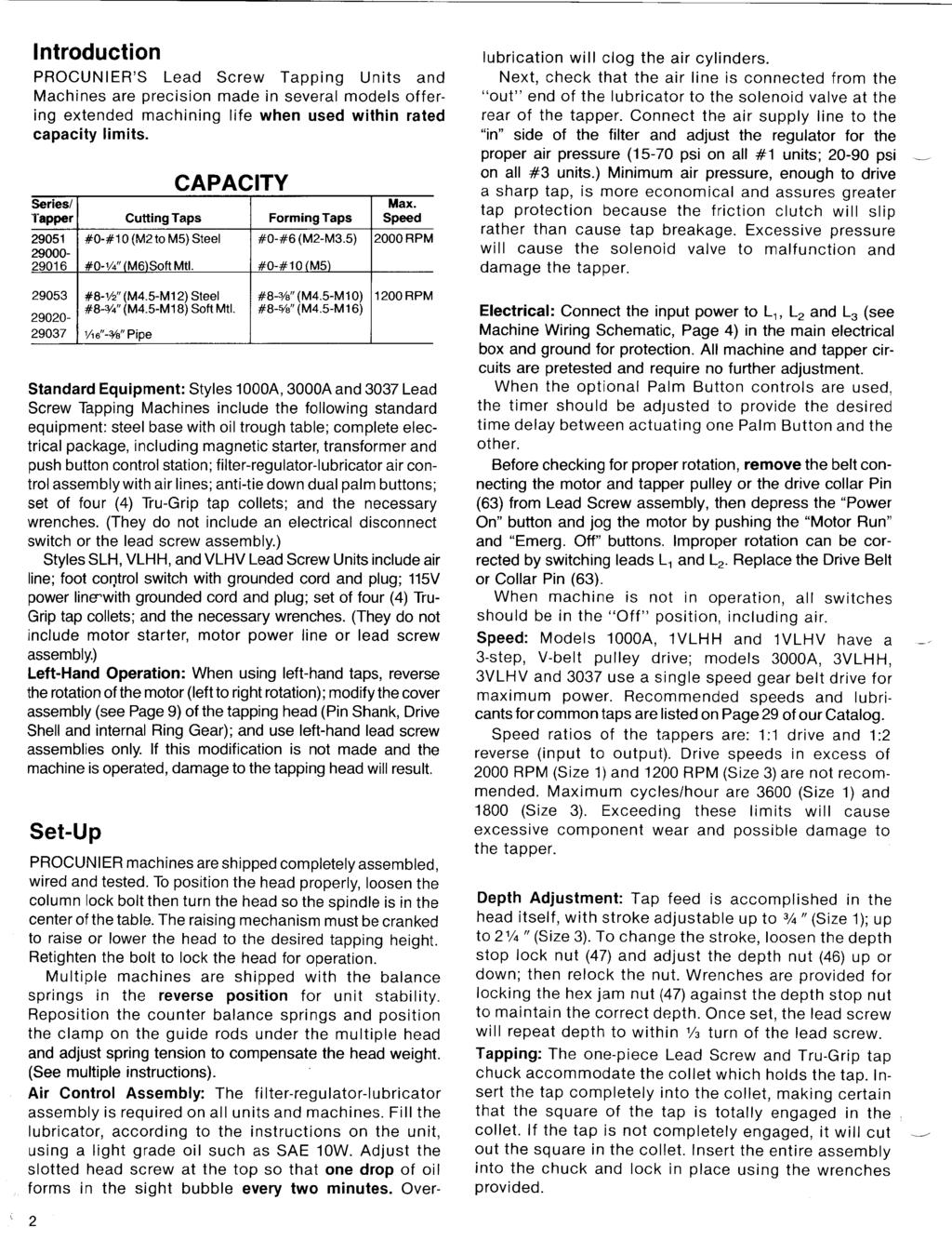
5 Disassembly Disassembly of the Tapping Head is easily accomplished by following the proper sequence: 1. Remove the top cover screws (15) and raise the cover assembly clear of body. 2. Remove the friction clutch (26) by first inserting wedges between the bottom of the cylinder yoke (39) and the top of the cylinders (36) to remove pressure from the clutch, as per diagram. 3. Place a 3/16" dia. rod through the splined spindle (25) to secure it from rotating. Remove the locknut (27) from the spindle (right hand thread). Pull the hex clutch (26) completely off the spindle. Clean the clutch by wiping with a cloth dipped in a good non-residue cleaning solution, such as alcohol or acetone. (Do not use paint thinner.) If the clutch is swollen, out of shape or will not clean thoroughly, replace the clutch. Do not sand, file or rough up clutch surfaces. Remove the reverse shell assembly (*) and wipe the inside of both the reverse shell and the drive shell (103), using a clean cloth or a fine (000) emery paper. Drain out all excess oil in the head; then place a drop of oil on the top of the three studs (17). Grease the inside of the reverse shell between the two bushings (32) and on the body bearing (23) with a good grade TEFLON impregnated grease and saturate the oil felt with #10 oil. When reassembling the tapper, insert the 2-piece split collar (28S) tapered side up, into the groove on the hex spindle (25), then place the lock ring (28L) over the split collar, then the clutch (26) making sure it is seated on the lock ring. Assemble the hex locknut (27) on the spindle threads and lock the assembly by torquing the nut to ft.-lbs. ( AL) and ft.-lbs. ( AL). Reposition the cover assembly (C) making sure the separator ring (29) is not jammed and tighten the screws (15). Before actual operation, test the head in all three cycles for a few minutes for correct operation. 5
6 Code No. Description Qty. Series Series Cam Shaft Button Shank Bushing Screw Switch Arm Actuator Switch Actuator Mounting Screw & Nut Actuator Switch Spacer Front Name Plate Actuator Cam W/Screw (2 pc.) Actuator Cam Spring Ground Nut Actuator Cam Shaft Cam Shaft Nut Screw Body W/Bushing (2) Stud Stud Nut Stud Plate Pinion Gear W/Bearing (21) BODY ASSEMBLY Code No. Description Qty. Series Series Pinion Bearing Oiler Felt Body Ball Bearing Screw Hex Splined Spindle Hex Clutch Lock Nut Lock Ring W/Split Collar L. Lock Ring Only S. Split Collar Only Separator Ring * Reverse Shell Assembly (includes 30, 31, 32, 33 & 34) Reverse Shell Only Reverse Gear W/Bushing (32) Reverse Gear Bushing Only Reverse Gear Lock Nut Screw Body Bushing
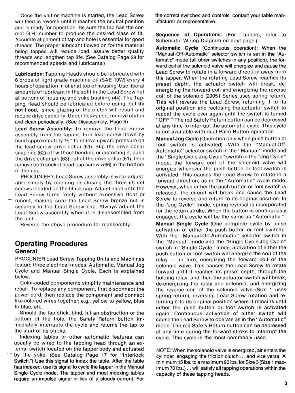
7 HOUSING ASSEMBLY Code Series Series Code Series Series No. Description Qty No. Description Qty Actuator Cam Shaft Cylinder Sleeve Cam Shaft Nut Cylinder Cap Screw Drive Collar Hex Splined Spindle Drive Collar Snap Ring Cylinder Housing W/Sleeve (59) Drive Collar Pin Lock Nut (includes 38) Lead Screw Cap Yoke Pin Screw Oiler Felt Cylinder Yoke Screw Yoke Ball Bearing Screw Retainer Plate Tru-Grip Nut Screw Pipe Plug Depth Stop Yoke Ass y 70. Solenoid Valve Ass y 120V (Includes 44, 45) (includes 71, 72, 73 & 74) Yoke Bushing Solenoid Valve Ass y 12V 45. Snap Ring (includes 71, 72, 73 & 74) Depth Stop Nut Solenoid Coil 120V Depth Stop Lock Nut Solenoid Coil 12V Shank Bushing Solenoid Adapter Cylinder Shaft Solenoid Connector Cylinder Bronze Bushing Solenoid Wire Insulator Piston Spring REGULAR Valve Mounting Screw Piston Spring HEAVY DUTY Solenoid Mounting Spacer Cylinder Piston Cup Solenoid Mounting Strap Piston Cup Washer Solenoid Nipple or Seal Cylinder Shaft Yoke Nut ' Air Line Cylinder Shaft Seal Cylinder Cap Gasket Cylinder Seal Retainer Tru-Grip Spindle Wrench Seal Retainer Screw Tru-Grip Nut Wrench Cylinder O Ring Seal Depth Nut Wrench 1/2"-9/16"
8 TAPPER ELECTRICAL COMPONENTS Code Series Series Code Series Series No. Description Qty No. Description Qty Screw Foot Control Plug Switch Arm Foot Control Receptacle Actuator Switch Rear Name Plate Actuator Mounting Screw Toggle Switch (2-Way) Front Name Plate Toggle Switch (3-Way) Ground Nut Power Line Cord W/Plug Body W/Bushing (2) Power Line Plug Only Push Button Switch Power Line Receptacle Relay 120V Terminal Board Relay 10V Terminal Board Screw Foot Control Assembly Relay Socket Foot Control Switch Relay Bracket
9
10
11
12 TROUBLESHOOTING Problem 1 Tapper does not tap to rated capacity or has lost its driving power. (A) Clutch is glazed, oil soaked or swollen - disassemble tapper, clean or replace clutch as described under Disassembly. (B) Check alignment of tap and hole, drill press speed, improper lubrication, dull or loaded tap, or part being tapped having undersized hole. (C)Air pressure too low - increase pressure. (D)Yoke bearing lock nut (37) has loosened. Problem 2 Lead Screw does not complete a full cycle, going down about 1/2", then reversing to original start position. (A)Actuator cam(13) not set correctly - adjust cam with set screw and lock in place. Problem 3 Lead Screw feeds forward to end of stroke but does not return. (A) Actuator switch (5) may be stuck in normally closed position (switch normally functions properly if a crisp click is heard when button is depressed). If necessary, replace actuator switch as in No. 5 below. Check new switch to assure that cam assembly (9) is in upper position when switch is depressed. (B) If actuator switch is not the cause, remove solenoid valve assembly (70) and check for coil burnout (smell). If defective, replace. (C) If depth stop nut (46) is set too low, tap will bottom in hole, or drive collar pin (63) is bottoming on splined spindle before depth stop nut engages. (D) Check tap for dullness, or if it is jammed in bottom of hole with chips - change style of tap and/or lubrication method. (E) Readjust bottom section of cam assembly (9) so that spring pressure holds the cam shaft (13) up. Problem 4 Lead Screw does not start cycle and there is no unusual noise when tapper is in Automatic or Manual Jog Cycle mode. (A)Check that actuator switch (5) is closed by actuator cam(9) - adjust. (B) Usual cause is lack of air pressure reaching cylinders. Check for broken actuator switch. To replace, disconnect power line, remove front and rear nameplates, and unhook actuator switch wires at rear of tapper. Remove the two actuator switch mounting screws (6) and pull out switch. NOTE: To check actuator switch, listen for sharp click when button is depressed or use test lamp. Install new switch, if needed, checking that it is engaged by actuator cam. Adjust cam by set-screw (10), if necessary, so that when Lead Screw is in UP position, switch is depressed. Reinstall nameplates. (C) If actuator switch is not malfunctioning, remove solenoid valve assembly (70) and check for burned coil, replacing if necessary. (D) Check that proper 115V power is getting to tapper. (E) Check 2- and 3-way switches (91 and 92) for proper operation. (F) Make sure air pressure is getting to the valve. Problem 5 Lead Screw does not start cycle and there is no unusual noise when run in Manual Single Cycle mode only. (A) Set selector switch on Automatic mode. (If unit does not work, see No. 5 above.) If tapper responds normally in this mode, check relay (85). To replace relay, remove front and rear nameplates, unhook all four relay wires and remove relay by unscrewing the mounting screws. Check relay contacts and check for burnt coil. When replacing relay, keep wires and terminals clear of casting. Problem 6 Flutters at bottom of stroke. (A) Actuator switch (5) malfunctioning - reset switch by moving actuator cam (9) downward toward tap. Problem 7 Squealing noise in tapper. Lead Screw may or may not act erratically. (A) Glazed clutch or frozen reverse shell assembly bushing is usual cause. Remove cover assembly clutch and reverse shell assembly (see Disassembly. ) Check gears for excessive wear or broken teeth. Check that pinion gears (20) are running free and not frozen. Check hex spindle shaft (25) for wear or ridges. Replace worn parts as necessary; remove excess oil; clean drive shell, reverse shell and clutch. Remove cylinder caps (60) from housing and clean. If piston assemblies (51) are removed, do not cut seals (55) or cups (52). (B) Check that depth stop yoke bushing (44) has not frozen to splined spindle or yoke. (C) Jammed tap, causing clutch (26) to slip. Turn off motor - free tap. Problem 8 Lead Screw not maintaining proper depth control. (A) Depth stop yoke bushing (44) may be frozen to splined spindle. Replace bushing and check all related parts for brass chips and worn or sharp edges. Check depth stop yoke assembly(43) for squareness between threaded rod and plate; check drive collar (61) for smoothness on flat surfaces. (B) Check actuator switch (5) for erratic operation - replace if necessary. (C) Solenoid valve(70) may be clogged Lvith oil or dirt, causing sluggish or erratic operation - disassemble and clean. (D) Clutch may be glazed - clean or replace RDL CAUTION: Always disconnect power and air lines to the tapper before removing nameplates or working on tapper head. Make sure that motor is not operating. 12
INSTRUCTION MANUAL. Style 1-AL and 3-AL Lead Screw Tapping Heads. Series and PROCUNIER SAFETY CHUCK CO. (Serial Nos.
 PROCUNIER SAFETY CHUCK CO. 304 Winston Creek Parkway Lakeland, Florida 33810-2866 Telephone 863-688-0071 FAX: 863-682-6233 Style 1-AL and 3-AL Lead Screw Tapping Heads Series 21000 (Serial Nos. B4870 and
Maintenance Information
 Form 16575334 Edition 1 April 2005 Electric Screwdrivers EL, EP and ET 34V DC Series Maintenance Information Save These Instructions WARNING Maintenance procedures have the potential for severe shock hazard
Instructions for INSTALLATION -- OPERATION -- MAINTENANCE of the SELAS AIR/GAS BLENDER VALVE. (for PROPANE/AIR, BUTANE/AIR AND OTHER BLENDS)
") DESCRIPTION The SELAS Blender Valve is a three-port, adjustable area valve which accurately mixes any two of a wide variety of gases. Air and Gas ports in a movable piston are matched to complimentary
DESCRIPTION The SELAS Blender Valve is a three-port, adjustable area valve which accurately mixes any two of a wide variety of gases. Air and Gas ports in a movable piston are matched to complimentary
Maintenance Information
 16606022 Edition 3 May 2014 Air Drill 728 Series Maintenance Information Save These Instructions Product Safety Information WARNING Failure to observe the following warnings, and to avoid these potentially
OPERATING INSTRUCTIONS AND SERVICE MANUAL
 OPERATING INSTRUCTIONS AND SERVICE MANUAL 55NAL--270-4 55NL--724-4 55RNL-2-LS-4- COMPLETE TOOL MODEL NO. CODE NO. 55NAL--270-4 20270 55NL--724-4 220724 READ SAFETY RECOMMENDATIONS 55RNL-2-LS-4-24089 BEFORE
Overhaul Special Tools Required
 1 of 31 Overhaul - Special Tools Required - Cylinder end seal remover attachment, 07NAD-SR3020A - Pilot collar, 07GAF-PH70100 - Valve seal ring sizing tool, 07NAG-SR3090A - Ball joint boot clip guide,
CONTROL VALVES. Installation, Maintenance & Operating Instructions. Read these instructions carefully before installation or servicing.
 KOSO HAMMEL DAHL CONTROL VALVES KOSO HAMMEL DAHL 253 Pleasant Street West Bridgewater, MA 02379 tel: 774.517.5300 fax: 774.517.5230 www.hammeldahl.com Installation, Maintenance & Operating Instructions
I & M 8000 Series. Ideal Installation Schematic. Preferred Installation. Trouble Shooting
 I & M 8000 Series 3170 Wasson Road Cincinnati, OH 45209 USA Phone 513-533-5600 Fax 513-871-0105 lowflow@richardsind.com www.lowflowvalve.com Installation & Maintenance Instructions for 8000 Series Low
Maintenance Information
 45530136 Edition 1 July 2008 Electric Screwdrivers EL 24V DC Series Maintenance Information Save These Instructions WARNING Always wear eye protection when operating or performing maintenance on this tool.
AUTOMATIC TRANSMISSIONS Mitsubishi F3A20 Series TRANSMISSION APPLICATION TABLE
 Article Text ARTICLE BEGINNING AUTOMATIC TRANSMISSIONS Mitsubishi F3A20 Series APPLICATION TRANSMISSION APPLICATION TABLE Vehicle Application Transmission Model Colt 3-Speed (1990-94)... F3A21 Colt Vista
Hydraulics. Part B, Section 1. This section covers the following unit configurations. 3700V 3800V 3900V
 Part B, Section 1 Model Voltage Pump Manifold Control This section covers the following unit configurations. 3500V 3700V 3800V 3900V All Piston (F) 4-Port (A) 6-Port (B or C) -Port (S or T) Vista Standard
Maintenance Information
 04581245 Edition 2 May 2014 Air Grinder, Die Grinder and Sander Series G2 (Angle) Maintenance Information Save These Instructions Product Safety Information WARNING Failure to observe the following warnings,
SERVICE PARTS LIST 1-1/8" ROTARY HAMMER MILWAUKEE ELECTRIC TOOL CORPORATION W. LISBON RD., BROOKFIELD, WI Drwg.
 00 0 200 204 276 EXAMPLE: Component Parts (Small #) Are Included When Ordering The Assembly (Large #). SERVICE PARTS LIST SPECIFY CATALOG NO. AND SERIAL NO. WHEN ORDERING PARTS PAGE 1 OF 3 BULLETIN NO.
Maintenance Information
 80234313 Edition 1 June 2006 Air Grinder, Die Grinder, Sander and Belt Sander Series G1 (Angle) Maintenance Information Save These Instructions WARNING Always wear eye protection when operating or performing
Maintenance Information
 16573370 Edition 2 February 2014 Air Grinder 99V Series Maintenance Information Save These Instructions Product Safety Information WARNING Failure to observe the following warnings, and to avoid these
Maintenance Information
 16573347 Edition 2 February 2014 Air Grinder Series 88H Maintenance Information Save These Instructions Product Safety Information WARNING Failure to observe the following warnings, and to avoid these
./#0#. 1"&." 1994 ELECTRICAL Suzuki of America Corp. - Starters. Swift
 !"" #$%!& '()!)((*(+,*)- 1994 ELECTRICAL Suzuki of America Corp. - Starters Swift Two types of starter motors are used, conventional and reduction gear. Both types of starters consist of yoke assembly,
I & M Mark 78 Series. Ideal Installation. Start-Up. Installation & Maintenance Instructions for Mark 78 Control Valves (1/2-1 )
") I & M Mark 8 Series 30 Wasson Road Cincinnati, OH 4509 USA Phone 53-533-5600 Fax 53-8-005 info@richardsind.com www.jordanvalve.com Installation & Maintenance Instructions for Mark 8 Control Valves (/ -
I & M Mark 8 Series 30 Wasson Road Cincinnati, OH 4509 USA Phone 53-533-5600 Fax 53-8-005 info@richardsind.com www.jordanvalve.com Installation & Maintenance Instructions for Mark 8 Control Valves (/ -
Maintenance Information
 16575128 Edition 2 May 2014 Air Grinder, Sander or Polisher 77A Series Maintenance Information Save These Instructions Product Safety Information Failure to observe the following warnings, and to avoid
Installation Manual. Model T680A/B Engine Brakes. For Mack 6 Cylinder, 4 Valve Head E6 and E7 Series Engines. Engine Brakes
 Engine Brakes Installation Manual Model T680A/B Engine Brakes For Mack 6 Cylinder, 4 Valve Head E6 and E7 Series Engines TecBrake P.O. Box 27822 Houston, Texas 77227 INSTALLATION MANUAL TECBRAKE T680A
Model 210HP Beadbreaker
 00020HP:99900657: 2040409 Model 20HP Beadbreaker PARTS AND SERVICE MANUAL IOWA MOLD TOOLING CO., INC. BOX 89, GARNER, IA 50438-089 TEL: 64-923-37 TECHNICAL SUPPORT FAX: 64-923-2424 MANUAL PART NUMBER 99900657
 1 of 16 1/10/2015 7:25 AM STARTER MOTOR 2009 Hyundai Accent 1.6L Eng GS REQUESTED INFORMATION DISASSEMBLY 1. Disconnect the M-terminal (A) on the magnet switch assembly (B). Fig 1: Identifying M-Terminal
Maintenance Information
 16572679 Edition 2 May 2014 Air Drill QP Series Maintenance Information Save These Instructions Product Safety Information WARNING Failure to observe the following warnings, and to avoid these potentially
CHAPTER 14 PARKING BRAKE
 1 page INDEX1 PARKING BRAKE 14-1 14-143E-05 CHAPTER 14 PARKING BRAKE 1Models FA and FB with LF05S TROUBLESHOOTING...14-2 SPECIAL TOOLS...14-3 INSPECTION AND ADJUSTMENT...14-4 PARKING BRAKE...14-7 14 PARKING
PARTS LIST FOR NO. 3 SERIES PISTOL AND T HANDLE SCREWDRIVERS
 PARTS LIST FOR NO. 3 SERIES PISTOL AND T HANDLE SCREWDRIVERS NON-REVERSING HANDLE ASSEMBLY (SERIAL NO S. STARTING WITH B & D ) Fig. Part Form A278F Date 10-00/B Page 1 of 6 4. 14309 Ring O 5. 14312 Ring
Model 306B H&J Transfer Case Service Manual
 Model 306B H&J Transfer Case Service Manual For innovation using today s technology in demanding situations call: Phone: (877) 327-2116 Fax: (586) 601-1904 e-mail: info@mixerandplantparts.com Mixer & Plant
Turbo 400 Trans Brake Valve Body Shift Pattern: Park Reverse Neutral 1st 2nd 3rd
 TCI 221500 Turbo 400 Trans Brake Valve Body Shift Pattern: Park Reverse Neutral 1st 2nd 3rd This Valve Body will neutralize at shut-down by putting shifter In 2nd gear position This Kit Contains: (1) Turbo
MODEL:D-1000X D-1000XLD D-1000Y D-1000YLD D-1000Z
 INSTALLATION & OPERATION MANUAL MODEL:D-1000X D-1000XLD D-1000Y D-1000YLD D-1000Z INDEX WARNINGS BEFORE INSTALLATION INSTALLATION OPERATION MAINTENANCE TROUBLE SHOOTING OUTSIDE DIMENSIONS ACCESSORIES &
CHAPTER 22 STARTER Models J05C-TD, J08C-TP and TR
 1 INDEX STARTER 22-1 22-114E-03 CHAPTER 22 STARTER TROUBLESHOOTING...22-2 STARTER...22-4 22 22-2 STARTER 1 page 1 TROUBLESHOOTING Symptom Possible cause Remedy Engine does not crank, or cranks slowly Key
Hydraulics. Part B, Section 1. This section covers the following unit configurations. 3400V 3500V 3700V
 Part B, Section 1 This section covers the following unit configurations. Model Voltage Pump Manifold Control 3100V 3400V 3500V 3700V All Piston (E) 4-Port (A) 6-Port (B or C) 2-Port (S or T) Vista Standard
Copper Sleeve, Unit Injector, Replacement
 Volvo Trucks North America Greensboro, NC USA This service bulletin replaces SB 237-46, Copper Sleeve, Unit Injector, Replacement dated 6.2007, publication no. PV776-20177417. DService Bulletin Trucks
1989 Jeep Cherokee. STEERING COLUMN' '1989 STEERING Jeep Steering Columns STEERING COLUMN STEERING Jeep Steering Columns
 STEERING COLUMN 1989 STEERING Jeep Steering Columns DESCRIPTION All models use collapsible steering columns. All columns have integral ignition switch and locking device. Optional tilt wheel is available
Service Jacks. Operating Instructions & Parts Manual. Model Number. Capacity 4 Ton 4 Ton Air/ Manual 10 Ton 10 Ton Air/ Manual HW93657/ HW93660
 Service Jacks Operating Instructions & Parts Manual Model Number HW93657 HW93667 HW93660 HW93662 Capacity 4 Ton 4 Ton Air/ Manual 10 Ton 10 Ton Air/ Manual Made in North America HW93657/ HW93660 HW93667/
Table 6-1. Problems and solutions with pump operations. No Fluid Delivery
 Table 6-1. and solutions with pump operations No Fluid Delivery Fluid level in the reservoir is low. Oil intake pipe or inlet filter is plugged. Air leak in the inlet line prevents priming or causes noise
I & M Mark 78 Series. Ideal Installation. Start-Up. Installation & Maintenance Instructions for Mark 78 Control Valves (1-1/2-2 )
") I & M Mark 8 Series 0 Wasson Road Cincinnati, OH 4509 USA Phone 5-5-5600 Fax 5-8-005 info@richardsind.com www.jordanvalve.com Installation & Maintenance Instructions for Mark 8 Control Valves (-/ - ) Warning:
I & M Mark 8 Series 0 Wasson Road Cincinnati, OH 4509 USA Phone 5-5-5600 Fax 5-8-005 info@richardsind.com www.jordanvalve.com Installation & Maintenance Instructions for Mark 8 Control Valves (-/ - ) Warning:
No. CLMP05 January 11, Parts Price List Clausing Lathes & Mills P.O. BOX 877 GOSHEN, IN PHONE (574) FAX (574)
 FAX (574)") No. CLMP05 January 11, 2005 P.O. BOX 877 GOSHEN, IN 46527-0877 PHONE (574) 533-0371 FAX (574) 533-0403 EMAIL info@clausingsc.com Website http://www.clausing-industrial.com Note: Please do not give credit
No. CLMP05 January 11, 2005 P.O. BOX 877 GOSHEN, IN 46527-0877 PHONE (574) 533-0371 FAX (574) 533-0403 EMAIL info@clausingsc.com Website http://www.clausing-industrial.com Note: Please do not give credit
Fisher 3024C Diaphragm Actuator
 Instruction Manual 3024C Actuator Fisher 3024C Diaphragm Actuator Contents Introduction... 1 Scope of Manual... 1 Description... 2 Specifications... 3 Installation... 5 Mounting the Actuator on the Valve...
TCI Turbo 400 Full Manual Valve Body. Shift Pattern: Park Reverse Neutral First Second Third. NOTE: You must reuse stock manual control valve.
 TCI 221100 Turbo 400 Full Manual Valve Body Shift Pattern: Park Reverse Neutral First Second Third This Kit Contains: (1) Turbo 400 Full Manual Valve Body (1) Separator Plate & Gaskets (1) Pressure Regulator
136R616G190 Lawn Tractor FST-16 (1996) Page 1 of 27 42" Mowing Deck
 Page 1 of 27 42 Mowing Deck") 136R616G190 Lawn Tractor FST-16 (1996) Page 1 of 27 42" Mowing Deck 136R616G190 Lawn Tractor FST-16 (1996) Page 2 of 27 42" Mowing Deck 3 97600A 1 S 42" Deck Ass'y. Code: N notates a new part (not previously
136R616G190 Lawn Tractor FST-16 (1996) Page 1 of 27 42" Mowing Deck 136R616G190 Lawn Tractor FST-16 (1996) Page 2 of 27 42" Mowing Deck 3 97600A 1 S 42" Deck Ass'y. Code: N notates a new part (not previously
Installation Manual For ISL98, ISL03, ISL07, ISC07
 Installation Manual For ISL98, ISL03, ISL07, ISC07 Table of Contents Section 1: Introduction... 3 Housing Identification... 3 Engine Identification... 3 Special Tools... 3 Automatic Transmissions... 3
Fig Variable Speed Valve Parts
 5 DISASSEMBLY OF VARIABLE SPEED CONTROL VALVE (Seal Replacement with Control Valve in the Bobcat). Remove seat and seat plate (Fig. ).. Remove variable speed control lever linkage rod. 3. Remove temperature
Heavy Duty Miniature Quick-Change Applicator (End-Feed Type) with Mechanical or Air-Feed Systems
 with Mechanical or Air-Feed Systems") Heavy Duty Miniature Quick-Change Applicator (End-Feed Type) with Mechanical or Air-Feed Systems Instruction Sheet 408-8039 02 JUN 16 Rev G Ram Post Wire Disc Insulation Disc Insulation Crimper Stripper
Heavy Duty Miniature Quick-Change Applicator (End-Feed Type) with Mechanical or Air-Feed Systems Instruction Sheet 408-8039 02 JUN 16 Rev G Ram Post Wire Disc Insulation Disc Insulation Crimper Stripper
Pneumatic Corner Drill
 Maschinenfabrik GmbH Pneumatic Corner Drill Type 2 1602 0030 Illustration can differ from the original Operation and Maintenance Manual Compiled: 31.07.08 216020030_en.doc Page 1 of 12 TECHNICAL SPECIFICATION
CHAPTER 15 WINCH MAINTENANCE. This chapter contains maintenance instructions for disassembly and repair of winch components at the Direct
 CHAPTER 15 WINCH MAINTENANCE This chapter contains maintenance instructions for disassembly and repair of winch components at the Direct 15-1. INTRODUCTION Support maintenance level. Some subassemblies
MAINTENANCE MANUAL DI 16
 MAINTENANCE MANUAL DI 16 0.2-1.6% Press Ctrl + L for full screen 1 STANDARD INSTALLATION Inlet Outlet Optional accessories: Pressure regulator Solenoid valves Water meter Flow restrictor 200 Mesh/ 80 micron
Maintenance Information
 80234313 Edition 2 May 2014 Air Grinder, Die Grinder, Sander and Belt Sander Series G1 (Angle) Maintenance Information Save These Instructions Product Safety Information WARNING Failure to observe the
70 Series 8700 End Mount Three Phase Brake Instructions IP56 (NEMA 4) Housing
 Housing") Bulletin No. BK4773-3 (08/2016) 70 Series 8700 End Mount Three Phase Brake Instructions IP56 (NEMA 4) Housing Read carefully before attempting to assemble, install, operate or maintain the product described.
Bulletin No. BK4773-3 (08/2016) 70 Series 8700 End Mount Three Phase Brake Instructions IP56 (NEMA 4) Housing Read carefully before attempting to assemble, install, operate or maintain the product described.
DIRACT BRAKES 70 SERIES 4 POST BRAKE INSTRUCTIONS
 Bulletin No. BK4605 (3/18) DIRACT BRAKES 70 SERIES 4 POST BRAKE INSTRUCTIONS IMPORTANT Read this bulletin carefully before installing or operating this brake. Failure to comply with these instructions
OpTK. Product Instruction Manual. Spring Cylinder Rotary Actuators INTRODUCTION SAFETY INFORMATION INSTALLATION. Leading Technologies For Control
 Leading Technologies For Control Product Instruction Manual OpTK Spring Cylinder Rotary Actuators TABLE OF CONTENTS INTRODUCTION Safety Information... pg. 1 Unpacking... pg. 1 INSTALLATION... pg. 1 PREVENTIVE
70 Series 8700 Coupler 2-pc Hub & Shaft Three Phase Brake Instructions IP43 & IP56 (NEMA 2 & 4) Housing
 Housing") Bulletin No. BK4775-3 (08/2016) 70 Series 8700 Coupler 2-pc Hub & Shaft Three Phase Brake Instructions IP43 & IP56 (NEMA 2 & 4) Housing Read carefully before attempting to assemble, install, operate or
Bulletin No. BK4775-3 (08/2016) 70 Series 8700 Coupler 2-pc Hub & Shaft Three Phase Brake Instructions IP43 & IP56 (NEMA 2 & 4) Housing Read carefully before attempting to assemble, install, operate or
Service Manual. #19 Gearmatic Winch
 Allis Chalmers Service Manual #19 Gearmatic Winch Service Manual THIS IS A MANUAL PRODUCED BY JENSALES INC. WITHOUT THE AUTHORIZATION OF ALLIS CHALMERS OR IT S SUCCESSORS. ALLIS CHALMERS AND IT S SUCCESSORS
Maintenance Information
 16575219 Edition 4 October 2013 Air Screwdrivers QP1P, QP1S and QP1T Series Maintenance Information Save These Instructions Product Safety Information WARNING Failure to observe the following warnings,
STERNDRIVE UNIT 3 B GEAR HOUSINGS MR/ALPHA ONE/ALPHA ONE SS
 STERNDRIVE UNIT 3 B 23146 GEAR HOUSINGS MR/ALPHA ONE/ALPHA ONE SS Table of Contents Page Identification........................... 3B-1 Specifications.......................... 3B-1 Torque Specifications................
SERVICE PARTS LIST SPECIFY CATALOG NO. AND SERIAL NO. WHEN ORDERING PARTS 1" D-HANDLE ROTARY HAMMER SERIAL NUMBER G43A See page 6.
 00 0 CATALOG NO. EXAMPLE: Component Parts (Small #) Are Included When Ordering The Assembly (Large #). = Component of the 14-4-525 522-21 Maintenance Service Kit SEE PAGE TWO FOR THE PROCEDURE ON CHECKING
Troubleshooting Guide: 355 Lights (12V)
") Troubleshooting Guide: 355 Lights (12V) Contents Description Refer To: Troubleshooting - Troubleshooting Chart Adjustments / Repair Procedures Bulb Replacing the Bulb Fuse(s) Replacing the Fuse (Ceiling)
Troubleshooting Guide: 355 Lights (12V) Contents Description Refer To: Troubleshooting - Troubleshooting Chart Adjustments / Repair Procedures Bulb Replacing the Bulb Fuse(s) Replacing the Fuse (Ceiling)
Model DFR 070/156/220 Rotary Actuator
 Figure 1 DFR 156 TABLE OF CONTENTS General 2 Actuator Assembly 18 Scope 2 Bushing / Yoke Assembly 18 Principles of Operation 2 Spring Barrel Assembly 18 Safety Caution 2 Diaphragm Plate Assembly 20 Specifications
REPAIR MANUAL URW SERIES. URW-6, 8, 9, 10 & 12 Series Repair Manual
 REPAIR MANUAL URW SERIES URW-6, 8, 9, 10 & 12 Series Repair Manual Contents Page 1. Tools Needed for Repair 1 2. Disassembly and Reassembly of the Cam Casing 2-4 3. Disassembly and Reassembly of the Gear
MANUAL TRANSAXLE Return to Main Table of Contents
 MANUAL TRANSAXLE Return to Main Table of Contents GENERAL... 2 MANUAL TRANSAXLE CONTROL... 12 SHIFT LEVER ASSEMBLY... 14 MANUAL TRANSAXLE... 15 MANUAL TRANSAXLE ASSEMBLY... 17 FIFTH SPEED SYNCHRONIZER
GH-BETTIS OPERATING & MAINTENANCE INSTRUCTIONS DISASSEMBLY & ASSEMBLY FOR THE T80X-M4-S DOUBLE ACTING SERIES HYDRAULIC ACTUATORS
 GH-BETTIS OPERATING & MAINTENANCE INSTRUCTIONS DISASSEMBLY & ASSEMBLY FOR THE T80X-M4-S DOUBLE ACTING SERIES HYDRAULIC ACTUATORS -S INDICATES CYLINDERS ARE IN TANDEM PART NUMBER: 100121 REVISION "A" ECN
Maintenance Information
 51984144 Edition 6 May 2014 Air Paving Breaker MX60 & MX90 Maintenance Information Save These Instructions Product Safety Information WARNING Failure to observe the following warnings, and to avoid these
Flow Line Controls. Installation & Operations Manual SERIES 20/21 Pneumatic Actuators
 Flow Line Controls Installation & Operations Manual SERIES 20/21 Pneumatic Actuators Flow Line Controls, Inc. P.O. Box 677 Schriever, LA 70395 Phone: 985-414-6003 Toll Free 1-800-815-9226 Fax 985-414-6072
20. Install and tighten the cap screws that hold the end frame and field frame together
 4006-30 19. Fill the oil reservoir in the bearing bore of the end frame with SAE 10 engine oil. Then put the the end frame on the armature shaft. Align the marks on the end frame and field frame and push
SECTION steering mechanism
 07-302.01/ 1 2011MR17 SECTION 07-302.01 GENERAL Description See Figure 1. The includes the steering wheel (1), the steering column, the miter box (3), the steering shafts (2 and 4), and the drag link (7).
TC20 Chain Driven Power Take-Off Overhaul Instructions
 TC20 Chain Driven Power Take-Off Overhaul Instructions Table of Contents Section Page Introduction 4 Ordering Repair Parts 4 General Information 5 Special Tools 6 Disassembly See Page 2 Reassembly See
Maintenance Information
 16575243 Edition 2 October 2013 Air Screwdrivers 1R Series Maintenance Information Save These Instructions Product Safety Information WARNING Failure to observe the following warnings, and to avoid these
Tooling Assistance Center
 Safeguards are designed into this application equipment to protect operators and maintenance personnel from most hazards during equipment operation. However, certain safety precautions must be taken by
PROPELLER SHAFT & DIFFERENTIAL CARRIER SECTIONPD CONTENTS
 PROPELLER SHAFT & DIFFERENTIAL CARRIER SECTIONPD CONTENTS PREPARATION...2 PROPELLER SHAFT...5 On-Vehicle Service...6 Removal and Installation...7 Inspection...7 Disassembly...7 Assembly...8 ON-VEHICLE
PARTS CATALOG MODELS 320, 420, 520, 620, 820 GRAIN CART. Unverferth
 Unverferth Manufacturing Company, Inc. P.O. Box 357 Kalida, Ohio 45853 (419) 532-3121 FAX (419) 532-2468 Grain Carts PARTS CATALOG MODELS 320, 420, 520, 620, 820 GRAIN CART Unverferth Manufacturing Co.,
Principals of Operation... 1 Rotary Vane Priming Pump VPE and VPES... 2 Rotary Vane Priming Pump VPO and VPOS Priming Valve...
 Priming Systems Installation Priming Systems Operation & Maintenance Form No. F 1031 Section 2312 Issue Date 10/07/94 Rev. Date 02/27/06 Table of Contents Illustrations Principals of Operation...........................
STERILMATIC DIGITAL ELECTRIC STERILIZER PARTS AND SERVICE MANUAL
 STERILMATIC DIGITAL ELECTRIC STERILIZER PARTS AND SERVICE MANUAL EFFECTIVE JULY 19, 2017 Superseding All Previous Parts Lists. The Company reserves the right to make substitution in the event that items
Valtek Auxiliary Handwheels and Limit Stops
 Valtek Auxiliary s and Limit Stops Table of Contents Page 1 General information 2 Installation 2 Side-mounted handwheels, size 25 and 50 (linear actuators) 3 Side-mounted handwheels, size 100 and 200 (linear
Maintenance and Repair
 Maintenance and Repair WARNING ALWAYS shut off the engine, remove key from ignition, make sure the engine is cool, and disconnect the spark plug and positive battery terminal from the battery before cleaning,
Fisher 657 Diaphragm Actuator Sizes and 87
 Instruction Manual 657 Actuator (30-70 and 87) Fisher 657 Diaphragm Actuator Sizes 30 70 and 87 Contents Introduction... 1 Scope of Manual... 1 Description... 2 Specifications... 2 Installation... 3 Mounting
MODELS 48 RA 48 BRA2 48 BRA4 48 BRAD 48 RAS 48 RAZ 48 RAD 48 RAC
 General Safety and Maintenance Manual Model Number 48BRA 48BRAZ 48BRAC 48BRAD Exhaust Direction Front or Side Throttle Type (L) Lever or (K) Safety Lever Speed 9000 to 11000 R.P.M. (11000 is Standard)
Steering Gearbox Disassembly
 Steering Gearbox Disassembly Steering Rack Disassembly 5. Unbend the lock washer. Before disassembling the gearbox, wash it off with solvent and a brush. Do not dip seals and O-rings in solvent. 1. Remove
Corken Compressor Repair
 Corken Compressor Repair Click photo to make move Gauge Openings Inspection plate with model and serial #s Oil filter and oil pump assembly Crankcase breather vent Crankcase breather location. If excess
MODELS 46 ARA 46 ARAS 46 ARAC 46 RASD
 General Safety and Maintenance Manual MODEL 46RAS shown with 4 Guard. Model Number Exhaust Direction Front Side Throttle Type (L) Lever (K) Safety Lever Speed 13000 to 14000 R.P.M (13500rpm is standard)
Model QED-D, QED-A, QED-L
 This supplement is for Field Service use only, as complete dis-assembly and re-assembly of the QED reducer by the customer is NOT recommended. This supplement only extends to single reduction QED units.
Maintenance Information
 Form 04584058 Edition 1 November 2004 Air Impactool 2141P and 2141PSP Maintenance Information Save These Instructions Disassembly General Instructions 1. Do not disassemble the tool any further than necessary
TCI Trans-Scat
 Page 1 of 5 Return to Instruction Sheet index TCI 400000 Trans-Scat Turbo Hydramatic 400-1965-Up This kit will allow you to re-program your transmission valve body. This kit will give you firm positive
Torqueflite Manual/Automatic Valve Body
 TCI 122400 Torqueflite Manual/Automatic Valve Body This valve body can be installed in a few hours by carefully following directions. Read all instructions first to familiarize yourself with the parts
Injector. General Information CAUTION. Use only the specified injector for the engine.
 Page 1 of 32 006-026 Injector General Information CAUTION Use only the specified injector for the engine. All engines use closed nozzle, hole-type injectors. However, the injectors can have different part
Operation and Maintenance Manual for BS and BH Hydraulic Torque Wrenches
 BOLTORQ Operation and Maintenance Manual for BS and BH Hydraulic Torque Wrenches It is operating manual of BS series and BH series wrenches, please read carefully and follow the instructions. Warning and
Hydraulic Impact Wrench Type
 M a s c h i n e n f a b r i k G m b H Hydraulic Impact Wrench Type 6 1520 0010 Illustration can differ from the original Operation and Maintenance Manual 615200010_en_Version_03 Page 1 of 19 TECHNICAL
Maintenance Instructions
 General Note These instructions contain information common to more than one model of Bevel Gear Drive. To simplify reading, similar models have been grouped as follows: GROUP 1 Models 11, 0, 1,, (illustrated),,
Maintenance Information
 45528270 Edition 1 June 2007 Barring Motor T480 Series Maintenance Information Save These Instructions WARNING Always wear eye protection when operating or performing maintenance on this Barring Motor.
SERVICE PARTS LIST. SPECIFY CATALOG NO. AND SERIAL NO. WHEN ORDERING PARTS M18 Sawzall STARTING SERIAL NO.
 Pull both Brush Tubes (25) back before removing or installing the Armature (2) to prevent damage to the commutator. Brush Tube SERVICE PARTS LIST SPECIFY CATALOG NO. AND SERIAL NO. WHEN ORDERING PARTS
SERIES OPERATION AND MAINTENANCE MANUAL
 SERIES OPERATION AND MAINTENANCE MANUAL This manual CONTAINS IMPORTANT WARNINGS, S and OTHER INSTRUCTIONS. Read and understand the instruction manual Carefully, before use and retain it for reference.
Liftgate Terminology
 SL-20 Series SL-20 Series Click the appropriate link below for the major component of the liftgate for which you are trying to find the correct part. If you are unsure of the name of the part in Waltco
FRP Ball Valves INSTALLATION & MAINTENANCE MANUAL
 FRP Ball Valves INSTALLATION & MAINTENANCE MANUAL FRP BALL VALVES TABLE OF CONTENTS MAINTENANCE AND INSTALLATION INSTRUCTIONS 1. 2. 2.1 2.2 2.3 2.4 GENERAL...Page 1 HANDLING...1 Receiving and Storing...1
TURBO DRIVE INSTALLATION MODEL 4380T KNEE FEED Sharp, Alliant & Others
 TURBO DRIVE INSTALLATION MODEL 4380T KNEE FEED Sharp, Alliant & Others NOTE This Turbo Drive Knee Feed is configured for mounting the feed on the front of the knee with the keypad facing left. The lead
OPERATION AND MAINTENANCE MANUAL for SERIES 7 AIR DRILLS
 03530896 OPERATION AND MAINTENANCE MANUAL for SERIES 7 AIR DRILLS Form P6532 Edition 10 February, 1994 TPD1388 IMPORTANT SAFETY INFORMATION ENCLOSED. READ THIS MANUAL BEFORE OPERATING TOOL. FAILURE TO
Installation Manual. Model T675A Engine Brakes. For Mack 6 Cylinder, 2 valve Head ENDT-673, 675, 676 & E6 Series Engines.
 Engine Brakes Installation Manual Model T675A Engine Brakes For Mack 6 Cylinder, 2 valve Head ENDT-673, 675, 676 & E6 Series Engines TecBrake P.O. Box 27822 Houston, Texas 77227 INSTALLATION MANUAL TECBRAKE
60 Series End-Mount Brake Instructions Standard Housing
 Bulletin No. BK4655 (04/18) 60 Series End-Mount Brake Instructions Standard Housing Read carefully before attempting to assemble, install, operate or maintain the product described. Protect yourself and
Magnesium Option, Late Model Front Seal, Viton, P/N 67256V Rear Seal, Viton, P/N 67257V Shifter Installed Heat Treated Yoke, P/N
 DESCRIPTION OPTION Magnesium Option, Late Model 80100L Front Seal, Viton, P/N 67256V 80109 Rear Seal, Viton, P/N 67257V 80110L Shifter Installed 80112L Heat Treated Yoke, P/N 62946-6 80119-6 Heat Treated
BRAKE SYSTEM Return To Main Table of Contents
 BRAKE SYSTEM Return To Main Table of Contents GENERAL... 2 BRAKE PEDAL... 10 MASTER CYLINDER... 13 BRAKE BOOSTER... 16 BRAKE LINE... 18 PROPORTIONING VALVE... 19 FRONT DISC BRAKE... 20 REAR DRUM BRAKE...
MAINTENANCE MANUAL FOR THERMOSTATIC TEMPERATURE REGULATING VALVE TRAC STYLE P
 MANUAL NUMBER P-EFS-1 MAINTENANCE MANUAL FOR THERMOSTATIC TEMPERATURE REGULATING VALVE TRAC STYLE P TRAC Regulator Company Inc. 160 South Terrace Avenue Mount Vernon, New York USA 10550-2408 Phone: (914)
COYOTE ENTERPRISES, INC. 9/10 BLAST WHEEL MAINTENANCE & ASSEMBLY MANUAL
 COYOTE ENTERPRISES, INC. 9/10 BLAST WHEEL MAINTENANCE & ASSEMBLY MANUAL Parts & Machinery for the Abrasive Blast Industry 27301 East 121st Street Coweta, Oklahoma 74429 (918) 486-8411 Fax (918) 486-8412
INSTALLATION, OPERATING AND MAINTENANCE INSTRUCTIONS D SERIES TABLE OF CONTENTS
 INSTALLATION, OPERATING AND MAINTENANCE INSTRUCTIONS D SERIES GENERAL INFORMATION TERMS CONCERNING SAFETY UNPACKING INSTALLATIONS VALVE MAINTENANCE TABLE OF CONTENTS VALVE DISASSEMBLY AND REASSEMBLY PLUG
DRIVE AXLE Volvo 960 DESCRIPTION & OPERATION AXLE IDENTIFICATION DRIVE AXLES Volvo Differentials & Axle Shafts
 DRIVE AXLE 1994 Volvo 960 1994 DRIVE AXLES Volvo Differentials & Axle Shafts 960 DESCRIPTION & OPERATION All 960 station wagon models use type 1041 rear axle assembly. All 960 4-door models use type 1045