TABLE OF CONTENTS. Parts Listing Blower Head & PTO Clutch Assembly Discharge Chute & Crank Rod Subframe... 42
|
|
|
- Shawn Garry Short
- 5 years ago
- Views:
Transcription
1
2
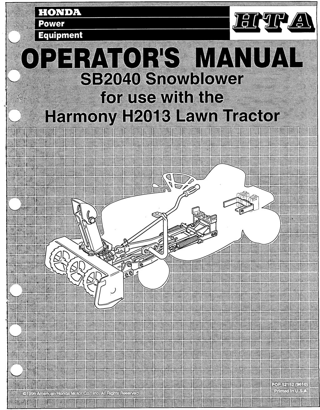
3 SI32040 Snowblower The information in this operator s manual is limited in application to the Honda SB2040 Snowblower (frame serial numbers ) when installed and used on a Honda Harmony H2013 lawn tractor. Before installing or operating this equipment. read this operator s manual and the owner s manual supplied with the lawn tractor. All information in this publication is based on the latest product information available at the time of printing. American Honda Motor Co., Inc. reserves the right to make changes at any time without notice and without incurring any obligation. No part of this publication may be reproduced without written permission. TABLE OF CONTENTS SAFETY MESSAGES... 2 DAMAGE PREVENTION MESSAGES... 2 THE IMPORTANCE OF INSTALLATION... 3 IMPORTANT SAFETY PRECAUTIONS... 3 Safety Labels... 4 Assembly and Installation... 5 Inventory Loose Parts... 5 Inventory Hardware Bags... 6 Hardware Measuring Chart... 8 Torque Values... 8 Assemble the Snowblower... 9 Installing the Snowblower Safety Recommendations Controls Preparing for Snow Removal Operating the Snowblower Snow Removal Methods Removing the Snowblower Maintenance & Adjustments Maintenance Schedule Adjustments Other Maintenance Items Parts Listing Blower Head & PTO Clutch Assembly Discharge Chute & Crank Rod Subframe Optional Accessories Tire Chains Headlight Kit Floor Mats Warranty Service Information This manual is a permanent part of the snowblower and must stay with the snowblower if resold. POP (961 0) 1
4 ~~ 1 SAFETY MESSAGES SB2040 Snowblower SAFETY MESSAGES Your safety and the safety of others are very important. We have provided important safety messages in this manual and on the snowblower. Please read these messages carefully. A safety message alerts you to potential hazards that could hurt you or others. Each safety message is preceded by a safety alert symbol and one of the following three words: DANGER, WARNING, or CAUTION. These words mean: You WILL be KILLED or SERIOUSLY HURT if you don t follow instructions. You CAN be KILLED or SERIOUSLY HURT if you don t follow instructions. You CAN be HURT if you don t follow instructions. Each message tells you what the hazard is, what can happen, and what you can do to avoid or reduce injury. DAMAGE PREVENTION MESSAGES You will also see other important messages that are preceded by the word NOTICE. This word means: (NOTICEI Your equipment or other property can be damaged if you don t follow instructions. The purpose of these messages is to help prevent damage to the snowblower, lawn tractor, other property, or the environment. 2 POP (961 0)
5 SI32040 Snowblower SAFETY MESSAGES THE IMPORTANCE OF INSTALLATION Proper installation is essential to operator safety and the reliability of the machine. Any error or oversight made by the technician assembling and servicing a unit can easily result in faulty operation, damage to the machine, or injury to the operator Improper service can cause an unsafe condition that can lead to serious injury or death. Follow the procedures and precautions in installation instructions and shop manuals carefully. Some of the most important safety precautions are given below. However, we cannot warn you of every conceivable hazard that can arise in performing this installation. Only you can decide whether or not you should perform a given task. Failure to properly follow installation instructions and precautions can cause you to be seriously hurt or killed. Follow the procedures and precautions in installation instructions carefully. IMPORTANT SAFETY PRECAUTIONS Make sure you have a clear understanding of all basic shop safety practices and that you are wearing appropriate clothing and safety equipment. When performing this installation, be especially careful of the following: 0 Read the instructions before you begin, and make sure you have the tools and skills required to perform the tasks safely. Make sure the engine is off before you begin any maintenance or repairs. This will help eliminate several potential hazards: 0 Carbon monoxide poisoning from engine exhaust. Be sure there is adequate ventilation whenever you run the engine. 0 Burns from hot parts. Let the engine and exhaust system cool before touching. 0 Injury from moving parts. Do not run the engine unless the instruction tells you to do so. Even then, keep your hands, fingers, and clothing away. Do not run the engine when any protective guard or shield is removed. To reduce the possibility of a fire or explosion, be careful when working around gasoline or batteries. Use only a nonflammable solvent, not gasoline, to clean parts. Keep all cigarettes, sparks, and flames away from the battery and all fuel-related parts. POP (9610) 3


6 Safety Labels Immediately replace any label that becomes damaged or unreadable. Contact a servicing Honda lawn tractor dealer for replacement label. mlm A D FAILURE TO FOLLOW SAFE OPERATING PROCEED URES MAY RESULT IN INJURY. I TO I I AVOID INJURY WHEN USING SNOWBLOWER *A REAR COUNTERWEIGHT IS REQUIRED TO COUNTERBALANCE SNOWBLOWER WEIGHT *MINIMUM 100 LBS. COUNTERWEIGHT IS RECOMMENDED *APPROVED TIRE CHAINS ARE REQUIRED I 'WHEN DISMOUNTING SNOWBLOWER, REMOVE REAR COUNTERWEIGHT 'DO NOT OPERATE ON SLOPES GREATER THAN 1% READ OPERATOR'S MANUAL I I TIMES. KEEP HANDS, FEET AND CLOTHING AWAY FROM POWER DRIVEN PARTS. *STOP ENGINE BEFORE LEAVING OPERATOR POSITION. *WAIT FOR ALL MOVEMENTS TO STOP BEFORE STARTING TO ADJUST, LUBRICATE, CLEAN OR UNCLOG THE MACHINE. KEEP THE AREA OF OPERATION CLEAR OF ALL PERSONS AND ANIMALS. KEEP ALL GUARDS AND SHIELDS IN PLACE. NEVER DIRECT DISCHARGE TOWARD BY- STANDERS, BUILDINGS, CARS ETC. 'ALWAYS USE A DUST MASK WHEN WORKING IN DUSTY CONDITIONS. KEEP PLASTIC MATERIALS AWAY FROM INTENSE HEAT AND OPEN FLAME. NEVER ALLOW PASSENGERS ON THE ATTACHMENT. KEEP HANDS OUT OF THIS DISCHARGE CHUTE WHILE / 4 POP (9610)

7 SI32040 Snowblower Assembly and Installation Assembly and Installation Proper installation of the SB2040 includes installing four (4) 26-lb. counterweights. These counterweights are not included with the snowblower and must be purchased separately. 1. Remove the lag bolts holding the blower head and the pulley assembly to the shipping pallet. 2. Remove the blower head and pulley assembly from the pallet. 3. Remove the loose parts box, then inventory the contents. Inventory Loose Parts HOLD-DOWN BRACKET WORM SUPPORT BRACKET L-SHAPED BRACKETS (2) WORM GEAR ANTIFRICTION RING LIFT PLATE (2) DISCHARGE GUARD COUNTERWEIGHT BRACKET DISCHARGECHUTE HANDLE SUBFRAME ASSEMBLY PUSH FRAME HANDLE SUPPORT These brackets (and associated hardware) are loosely installed on the subframe of units with serial numbers from POP (9610) 5


 511")
 handle hook (1) 711 6\" hex")
8 Assembly and Installation SB2040 Snowblower Inventory Hardware Bags Refer to the serial number (located on the right side of the blower head) and check all hardware. The following parts are included with all units: I 314 ID x 1-1 1/16" plastic bushing 112' flat washer (2) 511 6" flat washer (2) I 2.5 x 40 mm spring clip (1) handle hook (1) 711 6" hex nut (5) 114 x 112" hex bolt (4) I 112" hex nut (3) 112" lock washer (5) 6 POP (9610)

 I")
9 Snowblower Assembly and Installation The following parts are included only with serial number only. The parts indicated in the shaded boxes are not required for assembly and installation of the snowblower. The following parts are only included with serial number and up: I 5/16 x 3/4" hex bolt (4) I 318" flat washer (4) I 5/16 lock washer (E) PCP e@@ I 3/E x 1 hex bolt (5) POP (9610) 7
10 Assembly and installation SB2040 Snowblower Hardware Measuring Chart How to measure hardware and components: INCHES lt lr I I I I I I I I I I I I I I I I MILLIMETERS 518 in In 112 In In 5116In 1141n 00 5mm 6mm 8mm 10mm 12mm 14 rnm 16 rnm WASHERS ARE BY INSIDE DIAMETER NUTS ARE SPECIFIED BY INSIDE DIAMETER (AT THREAD DEPTH) INSIDE DIAMETER Torque Values Fastener I Size Nom ft-lb. Hex nut I bolt, Hex nut I bolt, Hex nut I bolt, Hex nut I bolt, 7116" Hex nut / bolt, 1/2" x 25 mm flange bolts POP (9610)

11 SB2040 Snowblower Assembly and Installation Assemble the Snowblower FOLLOW THESE INSTRUCTIONS CAREFULLY. Correct installation of this snowblower is essential for safe, reliable operation. Push Frame Installation Position the blower head on its front end as shown. Slide the push frame assembly into the blower head. 3. Install and finger-tighten two 7/16 x 1-1/4" hex bolts, 7/16" flat washers, 711 6" lock washers and 7/16" hex nuts to the front holes. 4. Install two additional x 1-1/4" hex bolts, 7/16" flat washers, 7/16" locking washers and 7/16" hex nuts to the rear holes. 5. Hold the edges of the push frame parallel to the edges of the blower head, then tighten all hardware. BELT GUW!W Install Belt to Idler Pulley 1. Locate the 3/8 x 1-3/4" hex bolt securing the idler pulley to the push frame. Loosen this bolt enough to allow the belt guard to be moved. 2. Locate the belt where it exits the bottom of the blower head. Install the belt onto the idler pulley with the wide, flat side of the belt against the pulley as shown. 3. Position the belt guard straight up. Adjust the gap between the guard and the pulley to 1/8-3/16" (3-5 mm) and tighten the hex bolt. PUSH FRAME POP (9610) 9
12 Assembly and Installation SB2040 Snowblower I,Install Push Frame to subframe 1. Position the push frame to the subframe as shown. 1-5/16" BUSHING (2 2. Install two 1-5/16" bushings, then install two 1/2 x 1-1/4" hex bob, 1/2" lock washers, and two 1/2" flat washers to the weld nuts on the push frame. Tighten the two nuts securely. For clarity, the drive belt is not shown in this illustration. Install PTO Clutch Assembly 1. Position the assembly as shown. Make sure the belt is fully enclosed inside the push frame, and the tensioner spring faces away from the blower head. 7/16" HEX NUT 318" HEX NUT A 7/16 LOCK WASHER 2.!nstall the assembly to the push frame using 3/8 x 1" hex bolt, 3/8" lock washer and 3/8" hex nut in the front (closest to the blower head) hole, then install a 7/16" x 1 hex bolt, 7/16" lock washer and 7/16" hex nut to the rear hole in the subframe. 318 x 1 " HEX BOLT 10 POP (961(
13 Sf32040 Snowblower Assembly and Installation Connect Lift Rods 1. Allow the subframe to pivot (while the blower head remains stationary), so you can connect the two lift rods to the subframe using the two 5/8 x 1-5/8" clevis pins and 4 x 80 mm spring clips. 2. Verify that the two counterbalance springs remain connected at both ends. / 4 x 80 rnm SPRING CLIP 518 x 1-5/8" CLEVIS PIN Engage Lockout Pin The counterbalance springs transfer the weight of the push frame (and blower head) against the subframe. This arrangement allows the height adjustment lever to easily raise and lower the entire blower head. The push frame must be locked into position (using the lockout pin) before the springs can be properly adjusted. I Once the counterbalance springs are adjusted, they are under tension. The lockout pin must be kept in the locked position until the entire snowblower is fully installed. 1. Place a suitable block of wood or other support under the push frame, so the subframe can pivot downward. 2. Adjust the position of the subframe as needed to slide the lockout pin through the push frame and into the corresponding hole in the subframe. Secure the lockout pin with a 3 x 65 mm spring clip. 3. Verify the lockout pin is correctly installed by attempting to pivot the subframe on the push frame. POP (9610) 11 I
14 Assembly and Installation SB2040 Snowblower Adjust Counterbalance Springs 1. Tighten the adjustment nut on each counterbalance spring bolt so the exposed thread length is 75 mm (3.0 inches). 2. Lift the subframe and remove the block of wood or support. After the counterbalance springs have been adjusted, they are under tension. Do not remove the lockout pin until the entire snowblower is fully installed on the lawn tractor. The effort required to raise and lower the blower head can be adjusted by varying the length of exposed thread on the spring bolts. See the Maintenance section for details. 75 mm (3.0 inches) U Install Lift Plates 1. Install a 3/16" roll pin into one hole on the 5/8 x /16" rod. Install one lift plate and metal bushing on the rod and slide them against the roll pin. 2. Insert the other end of the rod through the holes in the subframe as shown. Install the other metal bushing and lift plate, then a 4 x 80 mm spring clip. The remaining holes on each lift plate will attach to the two lifting arms on the lawn tractor when the snowblower is installed. METAL BUSHING (2) 12 POP (9610) i
15 SB2040 Snowblower Assembly and Installation Discharge Chute Assembly 1. Install the discharge guard on the chute as shown using two 3/8-3/4" hex bolts, 3/8" flat washers, 3/8" lock washers and 3/8" hex nuts. 2. Place the antifriction ring onto the blower head; the ring is keyed to the blower head so only one position fits. 3. Apply a generous amount of general purpose grease to the top lip of the antifriction ring. 4. Install the long (1-11/16") plastic bushing into the worm gear bracket. Apply grease to the inside surface of the bushing. DISCHARGE GUARD 114 x 314" HEX BOLT (2 1-5/16'' PLASTIC BUSHING 3/8" HEX NUT (2) 318" LOCK WASHER (2) 318" FLAT WASHER (2) 114 X 314" HEX BOLT (6) -RETAINING PLATE (3) WORM GEAR / / $ 114" HEX NUT (6) 5. Grease the inside of the shorter (1-5/16") plastic bushing then slide it onto the short shaft of the worm gear. Grease the long shaft on the worm gear, and install it into the bushing on the worm gear bracket. 6. Position the chute on the blower head. Get a helper to hold it in place if needed. 7. Install the two front retaining plates using four 1/4 x 3/4" hex bolts, lock washers and hex nuts. 8. Install the short shaft of the worm gear (with bushing) into the bracket on the blower head. 9. Use the 1/4 x 3/4" hex bolts to install the left rear retaining plate along with the crank handle bracket. 10. Apply a generous amount of general purpose grease to the worm gear and chute gear teeth. 11. Use the longer, 1/4 x 314" hex bolts to secure the right rear retaining plate, hold-down bracket, and the plastic chain cover. 314" HEX BOLT 114" L 114" HEX NUT POP (961 0) 13
16 Assembly and Installation SB2040 Snowblower I Skid Shoe Installation 1. Insert one 5/16 x 1" carriage bolt into the lower hole of each skid shoe. Loosely attach a 5/16" lock washer and 5/16" hex nut. / 5/16" CARRIAGE BOLT (2) I 2. Slip the carriage bolt head into the keyhole opening in the lower, rear outside corner of the blower head. 5/16" HEX NUT (2) /16" LOCK WASHER (2) 3. Install the other 5/16 x 1" carriage bolt, lock washer and hex nut as shown. Tighten both hex bolts securely. 4. Repeat for the other skid shoe on the other side of the blower head. 5. The holes in the skid shoes are slotted so the skid shoes may be adjusted. See the Operation chapter for details on adjusting the skid shoes. Installing the Snowblower Remove the Mower Deck Follow the procedure in the HZ073 Owner's Manualor HZ073 Shop Manual, and remove the mower deck and front links from the lawn tractor. Remove Optional Trailer Hitch and / or Grass Bag Supports: Remove the trailer hitch and/or the grass bag supports if either are installed on the lawn tractor The counterweight bracket cannot be installed with the trailer hitch or grass bag supports. Raise and Support the Lawn Tractor 1. Raise the front end of the lawn tractor, and then support it by placing a 4 x 4" board under each front tire. 2. Engage the parking brake, remove the ignition key, and disconnect the spark plug cap. 14 POP (961 0)

 the u-shaped bracket to the two I-shaped brackets using four 318 x 1 I' hex bolts and 3/8\" lock washers.")
17 SB2040 Snowblower 5/16" HEX BOLT (4 5/16'' LOCK Install Brackets 1. If already installed, remove the hardware and the I-shaped brackets from the subframe of the assembled snowblower. L-SHAPED BRACKET ON 2. Install the I-shaped brackets to the lawn tractor frame using two 5/16 x 3/4" bolts and 5/16" lock washers as shown. Make sure the I-shaped brackets are installed on the outside of the lawn tractor frame. 3. Remove the u-shaped bracket and hardware from the subframe. ' N I/ # RIGHT L-SHAPED BRACKET ON SIDE OF TRACTOR FRAME I 4. Loosely install (don't tighten) the u-shaped bracket to the two I-shaped brackets using four 318 x 1 I' hex bolts and 3/8" lock washers. 5. Raise the height adjustment lever as far as possible. '318 x 1" HEX BOLT (4) Install the Snowblower 1. Position the snowblower assembly directly in front of the lawn tractor. Raise and support the blower head, then slide the snowblower assembly user the lawn tractor so the subframe holes are about 1/4" further back from their corresponding holes in the u-shaped bracket. 2. Lower the height adjustment lever all the way down. 3. Connect the lift plates to the rear lift arms on the lawn tractor using the same spring clips and flat washers used for the mower deck. SPRING CLIP (2) FLAT WASHER (2) from MOWER DECK LIFTING ARM (2) (on lawn tractor frame) POP (9610) 15
18 SI32040 Snowblower 4. Slowly lift the subframe with the height adjustment lever, so the hole on the left side of the subframe aligns with the rear hole on the u-shaped bracket. Loosely install a single 3/8 x 1-1/4" bolt through the rear holes only on each side of the u-shaped bracket and secure with a 3/8" lock washer and hex nut. Make sure the subframe remains on the outside of the u-shaped bracket. For clarity, the L-brackets and lawn tractor frame are not shown in this illustration. 5. Raise the blower head enough so the forward holes in the subframe align with the holes on the tractor frame. Raise or lower the blower head to align the holes vertically, and push or pull the blower head to align the holes horizontally. Install two 1/2 x 1-3/4" hex bolts, 1/2" lock washers and 1/2" hex nuts 112" HEX NUT (2) 112" LOCK WASHER (2) FRONT Securely tighten the 3/8 x 1-1/4" bolts and 1/2 X 1-3/4" bolts Install two 3/8 x 1-1/4" hex bolts, lock washers and hex nuts into the front holes of the u-shaped bracket. For clarity, the L-brackets and lawn tractor frame are not shown in this illustration. Raise the height adjustment lever as far as possible. This will not be the highest position on the lawn tractor; do not force it any higher. Remove the supports from under the blower head. Lower the height adjustment lever all the way down. 10. Disengage the lockout pin by removing its spring clip, then pulling the lockout pin out slightly. You may have to have a helper lift the blower head slightly to relieve any tension on the lockout pin. 11. Replace the spring clip on the lockout pin to secure it in the disengaged position. 112 x 1-3/4" HEX BOLT (2) A /3/8 HEX NUT (2) 16 POP (9610)
19 1 St32040 Snowblower Connect Drive Belt & PTO Rod 1. Make sure the mower deck belt guard around the SILVER crankshaft pulley has been moved out of the way. This is typically done when the mower deck is removed. 2. Make sure the PTO clutch lever is OFF. 3. Install the snowblower drive belt to the crankshaft pulley, then install the belt guard. Tighten the silver-colored flange bolt securely. FLANGE BOLT 4. Install the connecting rod from the pivot on the u-shaped bracket to the slot on the PTO rod using the two flat washers and 2 x 26 mm spring clip. Make sure the connecting rod is positioned on the right-hand side of the pivot. FLAT WASHER (2) and 2x26mm SPRING CLIP Connect Turnbuckle 1. Unthread the eye bolt side of the turnbuckle and install a 5/16" jam nut onto the eye bolt threads, then install the eye bolt back on the turnbuckle. L PIVOT PLATE ON U-SHAPED BRACKET \ I 2. Connect the hook bolt end (tip of hook bolt must face out to the left side of the lawn tractor) of the turnbuckle to the pivot plate on the u-shaped bracket, and the eye bolt end of the turnbuckle to the tension spring on the belt tensioner pulley assembly. LEFT SIDE VIEW I HOOK BOLT POP (961 0) 17

20 SB2040 Snowblower Check Belt Routing Path 1. Move the PTO clutch lever to ON. Verify the belt has been routed as shown. RIGHT SIDE ENGINE CRANKSHAFT PULLEY TWIST IN BELT ON RIGHT SIDE PULLE Check Belt Guards and Gap Inspect the four belt guards on the PTO clutch assembly. Verify each guard is positiioned as shown. Check the spacing between the the two pulleys and the four belt guards. Verify there is a gap of 1/8-3/16" (3-5 mm). FIXED (LEFT SIDE) PULLEY \\-- -d REAR VIEW ft-lb. (27-31 Nrn) MOVEABLE (RIGHT SIDE) PULLEY 18 POP (9610)
21 Adjust Belt Tension 1. Locate the thin metal plate inside the tensioner spring. This plate is the belt tension indicator. 2. Loosen the jam nut on eye bolt side of the turnbuckle, and then turn the turnbuckle until the square tip of the belt tensioner indicator is flush with the end of the tensioner spring. Tighten the nut securely. PIVOT PLATE ON U-SHAPED BRACKET ADJUST TURNBUCKLE SO INDICATOR IS SPRING COIL HOOK BOLT Install Crank Handle and Crank Support Install the plastic grip onto the end of the crank handle rod. Locate and remove the two 8 x 18 mm flange bolts on the left front side of the lawn tractor frame, just to the rear of the left front tire. Install the crank support to the lawn tractor frame using two 8 x 25 mm hex bolts and 8 mm flat washers. Install the grommet into the end of the crank support, then insert the crank handle through the bushing. (The top most hole is used for mounting the optional light kit.) Slip the J-hook into the tip of the worm gear, then install the other end into the crank handle. Secure it with a 2.5 x 40 mm spring clip. LEFT SIDE VIEW v /- ' J-HOOK TENSION INDICATOR (red plate inside spring coils) CRANK SUPPORT \ I x 25 rnrn HEX BOLT (2) POP (9610) 19


22 SB2040 Snowblower Counterweight Installation 8 x 25 mm HEX BOLT (2) 8 mm FLAT WASHER (2) L\ Install the rear counterweight bracket to the rear of the lawn tractor frame as shown. Use two 8 x x HEX BOLT\ mm hex bolts and 8 mm flat washers for the sides and a 1/2 x 1-1/4" hex bolt, 1/2" diameter lock washer and 1/2" hex nut for the center. Hang the four, 26 Ib. counter weights (purchased separately) onto the bracket. Install a 4 x 80 mm spring clip into one hole of the 3/4 x 11-7/8" inch rod. Position the other tip of the rod through the rounded slots in the counterweights, then secure the rod in place by installing a 4 x 80 mm spring clip in the remaining hole. 112" HEX NUT SPRING CLIP Install Rear Reflectors Clean the rear fenders where the reflectors are to be installed. Remove the protective backing from the two reflectors and press them firmly onto the rear fenders separately) Verify Correct Installation a. Make sure the height adjustment lever is all the way up and the PTO clutch lever is OFF. Connect the spark plug cap, then start the lawn tractor and drive it off the 4 x 4" blocks. Drive the lawn tractor to a flat, level outdoor area. Stop the lawn tractor, set the parking brake ON, and remove the ignition key. Inspect the auger, discharge chute, subframe, PTO pulley assembly, snowblower drive belt and belt guards. Verify they are all correctly installed and all fasteners are securely tightened. Sit in the operator's seat, then start the lawn tractor and leave the parking brake ON. After the engine has warmed up for at least a minute, move the throttle to 6 (FAST), then engage the PTO clutch lever. Verify snowblower operation, then raise and lower the height adjustment lever up and down a few times. Move the PTO clutch lever to OFF, stop the lawn tractor's engine, and remove the ignition key. Reinspect the auger, discharge chute, belt and pulley assembly and make sure they are not loose, broken or damaged. Inspect the belt path and make sure the snowblower drive belt is properly routed on all pulleys and belt guards. Verify the guard-pulley gap is set correctly on all belt guards. 20 POP (9610)
23 SB2040 Snowblower Safety Recommendations Safety Recommendations Introduction 1. The snowblower is capable of amputating hands and feet and throwing objects. Failure to observe the following safety instructions could result in serious injury or death. 2. Serious accidents which may cause injury or property damage can occur if the following safety guidelines are not followed. The operator is solely responsible for accidents or hazards that occur when using the snowblower. Preventing accidents is the responsibility of every equipment operator. Accidents can be prevented. Be careful before, during and immediately after use of any powered equipment. The following general safety precautions must be fully understood and followed during operation. Review these instructions frequently and never take chances. If you do not understand any part of this manual or need assistance, contact your authorized, servicing Honda lawn tractor dealer. Training 1. Read, understand and follow all instructions in this manual and on the snowblower before starting. To order a replacement manual, contact an authorized, servicing Honda lawn tractor dealer, or Honda Customer Service (page 45). 2. Read and understand the H2013 Owner s Manual. 3. Allow only responsible adults, who are familiar with the instructions, to operate the machine. 4. Know the location of all controls before operating the machine. Know how to stop the engine and attachment quickly in case of emergency. Familiarize yourself with all safety and operation labels on the machine and attachment. If these labels are damaged or not legible, clean or replace them. Preparation 1. Wear proper clothing when operating the snowblower. Always wear sturdy footwear (preferably steel-toed shoes) and hearing protection during operation. a) Wear heavy, leather gloves whenever working near or servicing any cutting edges on the snowblower. b) Do not wear loose fitting clothing, jewelry, scarves, ties, etc., which may get caught in moving parts. Tie up or restrain long hair. c) Do not operate the snowblower while barefoot. d) Do not wear sandals e) Wear long trousers. f) Wear hearing protection. g) Do not operate the snowblower when tired, ill, or under the influence of alcohol and/or other drugs. 2. Be prepared for an emergency. Keep a first aid kit and fire extinguisher handy. Keep emergency telephone numbers for ambulance, fire, hospital, doctor and rescue near your telephone. POP (9610) 21
24 Safety Recommendations SB2040 Snowblower Before Operation 1. Before each use, clear work area of objects such as rocks, toys, wire, sleds, etc., which could be picked up and thrown. 2. Keep the snowblower in safe operating condition. Check the following each time before use: a) All hardware for tightness (refer to the torque table for details). b) Inspect auger and fan blades for wear or damage. Broken pieces thrown from worn or damaged auger or fan can cause serious injury. c) Check for and maintain correct lawn tractor tire pressure. Check tires for cuts or bubbles. Check wheels for damage or for missing hardware. Repair or replace as required. d) Check the engine oil level and add oil as required. If oil level falls below the maximum fill mark, do not run engine. 3. Do not operate the snowblower without safety devices and shields in place and operating properly. 4. Use counterweights (purchased separately) for extra traction and proper balance. 5. Check the lawn tractor brake function frequently. Adjust and service as required. 6. The lawn tractor is equipped with a safety interlock system, designed to shut off the engine when the operator leaves the seat while an attachment is running or the parking brake is not engaged. If the interlock system is not working properly, repair it before operating the snowblower. Correct any malfunction before using the snowblower or the lawn tractor. Operation When starting the lawn tractor engine: a) Disengage the PTO. b) Set the parking brake ON c) Move the shift lever to NEUTRAL. Remain seated when starting the lawn tractor engine and during operation. Operate with feet flat on the lawn tractor running boards at all times. Keep hands, feet, face, hair and clothing away from rotating parts. Stop engine before unclogging chute. When operating the snowblower: Disengage the PTO lever, shut off engine, set the parking brake ON, remove the ignition key, and wait for all moving parts to stop before unclogging discharge chute or auger blades. Run the snowblower for a few minutes after use to discharge any leftover snow; this will prevent freeze-up of the auger and / or fan. Disengage the PTO lever when transporting to work area, or when the snowblower is not in use. Be aware of snowblower discharge direction and do not point it at anyone. Do not operate without discharge deflector in place. If you strike a foreign object, disengage the PTO, shut off the engine, set the parking brake on, and remove the ignition key. Inspect for and repair any damage before operating the equipment again. Never carry passengers. Passengers interfere with safe operation of the snowblower. Passengers could be struck by foreign objects and/or be thrown from the machine and could be severely injured. 10. Be sure the area is clear of other people before operation. Stop the machine if anyone enters the area. Do not operate the machine with children, pets, or other nearby. 22 POP52152 (9610)
25 SI32040 Snowblower Safety Recommendations 11. As a general rule, do not operate the machine in reverse. If it is absolutely necessary to back up: a) Disengage the PTO clutch. b) Check the area on the ground directly behind the machine. c) Continue to observe area down and to the rear while backing up. 12. Approach blind corners cautiously. 13. Always observe the terrain. Watch for and avoid obstacles, stay away from holes, ditches, soft or steep embankments and other potentially dangerous terrain. 14. Wet surfaces reduce traction and stability. Always maintain proper traction. Grip the lawn tractor steering wheel firmly. 15. Slow down before turning. 16. Watch out for traffic when operating near or crossing roadways. 17. Never leave a running machine unattended. Always disengage the PTO lever, set the parking brake ON, and remove the ignition key before dismounting. Children 1. Accidents can occur if the operator is not alert to the presence of children. Children are often attracted to the machine and the snowblowing activity. Never assume that children will remain where you last saw them. 2. Never allow children to operate the machine, even under adult supervision. Local regulations may restrict operator age. Allow only responsible adults, who are familiar with these instructions, to operate this unit. 3. Never carry children as passengers. They may fall off or be seriously injured or interfere with safe machine operation. 4. Keep children out of the work area and under the watchful eye of another responsible adult. 5. Be alert and turn off the machine if children enter the area. 6. Before and when backing up, look behind and down the operating area for small children. 7. Use extreme care when approaching blind corners, drifts, trees or other objects that may obscure vision. 8. Keep children away while performing maintenance or adjustments. POP (9610) 23
26 Safety Recommendations SB2040 Snowblower Slope Operation 1. Slopes are a major factor in loss-of-control and tip-over accidents, which can result in severe injury or death. All slopes require extra caution. If you cannot back up the slope or feel uneasy on it, do not operate on a slope. 2. Remove obstacles such as rocks, tree limbs, etc. 3. Watch for holes, ruts, or bumps. Uneven terrain could overturn the lawn tractor. 4. Always remove snow up and down the face of slopes, never across. Do not operate near drop-offs, ditches, or embankments. The lawn tractor could suddenly overturn if a wheel goes over the edge of a cliff or ditch, or if an edge caves in. 5. Always use counterweights for stability and extra traction. 6. Do not turn on slopes unless necessary, and then, move the PTO clutch lever to OFF, then turn slowly and gradually downhill. 7. Do not start or stop suddenly when going up or down a slope. Keep all movement on slopes slow and gradual. Do not make any sudden changes in speed or direction. Use a low gear setting so you will not have to stop or shift while on the slope. 8. If the machine is unable to continue moving uphill, move the PTO clutch lever to OFF, check the area on the ground immediately behind the machine, watch the area to the rear, and proceed backward slowly. 9. Do not operate unit on steep slopes where there is a risk of an overturn. Do not operate the lawn tractor on slopes greater than 10% grade. Use a slope gauge to check the slope if you are not sure. 10. Use extra care when using this attachment. The extra weight can change the stability of the lawn tractor. 11. Do not try to stabilize the unit by putting your foot on the ground. 12. Do not park the machine on a hill. ~ 24 POP (9610)
27 St32040 Snowblower Safety Recommendations Stopping 1. Before leaving operator s position or leaving the machine unattended: a) Bring the lawn tractor to a complete stop. b) Move the PTO clutch lever to OFF. c) Lower the snowblower all the way down. d) Set the parking brake ON. e) Shut off the engine and remove the ignition key. f) Wait for all moving parts to come to a complete stop. 2. Disengage the PTO clutch lever when transporting the lawn tractor or if the snowblower is not in use. Maintenance Before performing any service, adjustments or maintenance on the machine: a) Park the machine on a firm, level surface. b) Move the PTO clutch lever to OFF. c) Lower the snowblower all the way down. d) Move all control levers to NEUTRAL. e) Set the parking brake ON. f) Shut off the engine. Remove the ignition key. Allow the engine to cool. Always wear sturdy footwear (preferably steel-toed shoes), long trousers, hearing and eye protection while performing maintenance on the machine. Do not wear loose fitting clothing, jewelry, scarves, ties, etc., which could get caught in moving parts. Tie up or restrain long hair. Auger and fan blades are extremely sharp. Use caution when servicing. Wear heavy gloves. Keep children away while performing maintenance or adjustments. Keep nuts and bolts tight. Keep equipment in good condition. Never tamper with safety devices. Check their proper operation regularly. Replace or repair as necessary. Keep machine free of dirt and grim. Clean up oil or fuel spillage. Allow machine to cool before storing. Frequently check components and replace when necessary. Use only factory-approved replacement parts. Parts manufactured by others may not be of the same quality. Keep all safety and operation labels in place. If these labels are damaged or not legible, clean or replace them as needed. 10. Check the lawn tractor brake operation frequently. Adjust and service as necessary. 11. Chock lawn tractor wheels (place blocks of wood in front of and behind wheels) when performing maintenance with the parking brake off. Securely support unit if it must be raised for any reason. 12. Do not inflate the tires above recommended pressures. Use a clip-on chuck to inflate tires, with an extension long enough for you to stand to one side, and not over or in front of the tire assembly. POP (9610) 25
28 Safety Recommendations SB2040 Snowblower Controls Discharge Chute Rotation Crank Rotating this crank turns the discharge chute. TURNS CHUTE RIGHT TURNS CHUTE LEFT Discharge Chute Deflector This determines the angle at which snow is discharged from the chute. The two locking knobs on the sides hold the chute at the desired angle. ROTATE DEFLECTOR - Lockout Pin The blowerhead pivots up and down on the subframe. Use the lockout pin to lock the blowerhead so it doesn t pivot. This is necessary when servicing, removing or installing the snowblower. Get a helper to raise and lower the blowerhead so the lockout pin can be engaged or released. Always secure the lockout pin with the spring clip to prevent it from getting lost. 26 POP (9610)
29 SI32040 Snowblower Safety Recommendations Preparing for Snow Removal 0 Read the Safety Recommendations at the beginning of this section. 0 Park the lawn tractor on a flat, level surface, Engage the parking brake, and remove the ignition key. 0 Make sure the auger blades, blower head and discharge chute are free of any debris or objects. Verify the four counterweights (sold separately) are installed and properly secured to the rear frame. 0 If you have the optional tire chains installed, inspect them and make sure they are secure. 0 Inspect the position of the two skid shoes, and make sure they are properly positioned for conditions. See page 34 for skid shoe adjustment. Verify that the tension on the drive belt is correct. See page 19 for details on inspecting and adjusting drive belt tension. Position the Discharge Chute You can adjust the angle and direction of the discharged snow. The angle must be set while the lawn tractor is parked and the engine is off. To adjust the discharge angle: 1. Loosen the two locking knobs on either side of the discharge chute. 2. Position the deflector at the desired angle. Tighten the locking knobs. 3. You may need to experiment and readjust the deflector after a few trial runs. To adjust the discharge direction: 4. Rotate the crank handle and turn the discharge chute to the desired position. The crank will not rotate a full 360 degrees. Setting the Height Adjustment Lever Lift and move the height adjustment lever to the desired position. You can adjust the amount of effort required to raise the snowblower; see the Maintenance section for details. ~ ~~ POP (9610) 27
30 Safety Recommendations SB2040 Snowblower Operating the Snowblower Read the lawn tractor owner's manual carefully. Be thoroughly familiar with the controls and proper use of the lawn tractor. Know how to stop the lawn tractor and disengage the controls quickly. Never allow children to operate the snowblower. Never allow adults to operate the snowblower without proper instruction. Do no allow anyone other than the operator on the lawn tractor. Keep the area of operation clear of all people and pets. Clothing worn by the operator should be fairly tight and belted. Loose clothing should not be permitted because of the danger of getting into moving parts. Tie up or restrain long hair. 1. Start the lawn tractor. After the engine has warmed for at least a minute, move the throttle to Zr (FAST). 2. Verify that the blower head is properly positioned, then move the PTO clutch lever to ON. 3. Adjust the ground speed of the lawn tractor as needed. Use the shift lever to change ground speeds, never the throttle. For best performance, the throttle should always be set to 6 (FAST). Snow Removal Methods Use the following patterns to avoid discharging snow in unwanted locations and to prevent a second pass. For clarity, assume both methods are used on a rectangular area. If you can discharge snow to both sides, it is best to start in the middle of the rectangle. Operate the snowblower from one end to the other, discharging snow to both sides. This method permits you to leave the discharge chute in the same position. If you must discharge snow to only one side, start in one corner, then rotate the discharge chute with each pass. This method will require a bit more effort, but the snow will be discharge only to one side. w OKAY TO DISCHARGE SNOW TO THIS SIDE FINISH HERE 4 OKAY TO DISCHARGE SNOW TO THIS SIDE A START HERE ROTATE 7 CHUTE180' L L I V ROTATE\ FINISH HERE DISCHARGE SNOW TO THIS SIDE ONLY 20 POP (961 0)
31 SI32040 Snowblower Safety Recommendations You can be seriously injured by the fan or auger blades. The blades spin and can cut or amputate your hand or fingers. Never attempt to clear a clog with your hand; always use a stick at least 36" in length to clear a clogged discharge chute or auger. When removing snow, do not use the snowblower as a dozer blade to push snow. Let the snowblower works its way through deep drifts If the travel speed of the lawn tractor is too fast, the snowblower may become overloaded and clog. For best results, raise the snowblower and remove a top layer of snow. A second pass will remove the remaining snow. Always operate the lawn tractor with the throttle set to 6 (FAST). Using other throttle settings can reduce performance and clog the discharge chute... POP (961 0) 29
32 Removing the Snowblower SB2040 Snowblower Removing the Snowblower Make sure the PTO clutch lever is OFF. Drive the lawn tractor to a flat, level surface, turn the engine off, remove the ignition key and set the parking brake ON. Disconnect the spark plug cap. Lower the height adjustment lever all the way down. Raise the front tires and support them squarely on top of two 4 x 4" blocks of wood. 4. Remove the silver-colored bolt that holds the engine pulley belt guard to the right side of the lawn tractor frame. Allow the belt guard to fall down slightly, then remove the snowblower drive belt from the engine pulley. DRIVE BELT SILVER BELT GUARD PIVOT PLATE ON U-SHAPED BRACKET 5. Loosen the jam nut on the belt tension FRONT turnbuckle, then lengthen the turnbuckle enough to disconnect the J-bolt from the PTO pivot plate. LOOSEN JAM NUT REMOVE HOOK BOLT 6. Remove the 2 x 40 mm spring clip and two flat washers from the PTO connecting rod where it is connected to the PTO pivot plate. Allow the rod to fall clear from the pivot plate. Retain the spring clip and washers when reinstalling the snowblower or the mower deck. FLAT WASHER (2) and 2x26mm SPRING CLIP 30 POP (9610)
33 1 SB2040 Snowblower Removing the Snowblower 7. Remove the 3.5 x 80 mm spring clip from the lockout pin, then engage the lockout pin into the push frame. You may need to slightly raise or lower the blower head to get the holes in the push frame and subframe to line up; reinstall the spring clip when the lockout pin is engaged. 3 X 65 mm SPRING CLIP LOCKOUT PIN \ \ 8. Remove the 2.5 x 40 mm spring clip from the J-hook end of the chute crank rod. Remove the rod from the crank support. Remove the J-hook from the worm gear, then store the J-hook on the chute crank rod with the spring clip. 9. If desired, you may optionally remove the crank support by removing the two 8 x 25 mm flange bolts from the support. SPRING CLIP Install the two bolts back into the frame. IO. Raise the height adjustment lever all the way up; this will not be in the maximum position, so do not use excessive force. 11. Raise and support the blower head. Remove the two 1/2 x 3/4" hex bolts, 1/2" lock washers, and 1/2' hex nuts that hold the subframe to the lawn tractor frame. Adjust the support on'the blower head to relieve any binding on the mounting bolts. 112" HEX NUT (2) 112" LOCK WASHER ( 2)-y f 112 x 1-314" HEX BOLT - 2 ( POP (9610) 31


 FLAT WASHER (2) MOWER DECK LIFTING ARM (2) (on lawn tractor frame) 14. Remove the snowblower from underneath the lawn tractor.")
34 Removing the Snowblower SB2040 Snowblower 12. Lower the blower head slightly, then remove the four bolts that hold the u-shaped bracket to the subframe. 13. Remove the two spring clips and flat washers from the lift arms on the lawn tractor, then disconnect the two lift plates from the corresponding pins on the lift arms. Allow the lift plates to pivot and drop clear of the arms. Retain the clips and washers to reinstall the snowblower or mower deck. SPRING CLIP (2) FLAT WASHER (2) MOWER DECK LIFTING ARM (2) (on lawn tractor frame) 14. Remove the snowblower from underneath the lawn tractor. Remove the four bolts that hold the u-shaped bracket to the two I-shaped brackets. The two I-shaped brackets may remain on the lawn tractor frame; the brackets will not interfere with the installation and operation of the mower deck. \3/8 x 1" HEX BOLT (4) 32 POP (9610)
35 SB2040 Snowblower Removing the Snowblower 15. Remove one spring clip from the counterweight retaining rod, then remove the rod. Remove the four suitcase weights from the counterweight bracket. The bracket may remain on the lawn tractor as desired. However, the bracket must be removed before the optional hitch or grass bag kit supports can be installed. Follow the procedure in either the H2073 Owner s Manual or H2013 Shop Manual to install the mower deck. POP (9610) 33
36 Maintenance & Adjustments SB2040 Snowblower Maintenance & Adjustments Maintenance Schedule I E m t e chains Apply grease to antifriction ring Apply grease to bushings Apply grease to worm gear When Every two (2) hours As needed As needed As needed Notes use chainsaw oil use general purpose grease use general purpose grease use general purpose grease Inspect and adjust PTO spring tension Each use adjust tension if needed Adjustments You can be seriously injured by the fan or auger blades. The blades spin and can cut or amputate your hand or fingers. Always stop ttie engine, remove the ignition key, set the parking brake ON, and disconnect the spark plug cap before attempting any maintenance or adjustments. For best possible performance, the SB2040 features a number of adjustments: Skid Shoes The skid shoes should be adjusted based on the type of ground surface. For level, paved surfaces, adjust the skid shoes to permit mm 5/16'' HEX NUT (2 (3/16-1/4 inch) of clearance between the bottom edge of the blower head and the ground. For uneven or gravel surfaces, set the clearance to mm (1/2-5/8 inch). To adjust the skid shoe position, loosen (don't remove) the two hex nuts on the skid shoe, position the shoe as needed, then tighten the hex nuts. Recheck the measurement and repeat if necessary. " CARRIAGE BOLT (2) 16" LOCK WASHER (2) 34! POP (9610)
37 SB2040 Snowblower Maintenance & Adjustments Height Adjustment Lever Effort You may vary the amount of effort required to raise the blower head with the height adjustment lever. This is done by lengthening or shortening the exposed threads on the two counterbalance spring adjustment bolts. This balances the weight of the blower head against the springs, making the blower head easier (or harder) to lift with the height adjustment lever. However, if the blower head does not have enough weight, it may float above the surface of the snow. For this reason, the recommend setting is to leave 75 mm (3 inches) of exposed thread. This setting offers a good compromise between lifting effort and blower head weight. To decrease lifting effort, increase the length of the exposed threads by tightening the hex nut on each bolt. To increase effort, loosen the hex nut on each bolt. When making any adjustments, always make sure the length of exposed thread is the same for both bolts. 75 rnrn (3.0 in.) Blower Head Angle You may adjust the angle of the lower edge of the blower head. This adjustment will allow the blower head to tilt forward or backward slightly. Engage the lockout pin (page 11). Locate and loosen (don't remove) the four 7/16"hex boltsthat attach the blower head to the push frame (see illustration at top of page 10). Hold the blower head at the desired angle and tighten the four bolts securely. Disengage the lockout pin. Lubrication Chain The drive belt operates two chains inside the blower head. One chain runs the discharge fan and the other drives the auger. Both chains must be lubricated on a regular basis for proper operation. Always park the lawn tractor on a flat, level surface, engage the parking brake, and remove the ignition key before attempting to lubricate any of the chains. Auger Drive Chain: Apply chain saw oil to the main auger sprocket and chain located on the right side of the blower head. Put on heavy gloves and turn the auger to lubricate the rest of the chain. Discharge Fan Chain: Remove a 1/4" hex bolt, retaining plate, lock washer, hex nut and chain cover hold-down bracket from the right rear of the discharge chute. Remove the plastic chain cover from the rear of the blower head to expose the discharge fan chain. Apply chain saw oil to the two sprockets and chain. Installation is the reverse of removal. Discharge Chute & Worm Gear 114" L 114" HEX NUT 114 x 314" HEX BOLT Apply a liberal amount of general purpose grease to the outer edge of the antifriction ring on the base of the discharge chute. Apply grease to the worm gear and the sector on the discharge chute. Bushings Apply a liberal amount of general purpose grease to the insides of the worm gear bushings and the crank handle bushing. Wipe away any excess grease from the outside of each bushing. I POP (961 0) 35
38 IMaintenance & Adjustments Snowblower Other Maintenance Items Shear bolt Replacement The auger and discharge fan both have special shear bolts that are designed to break if either the auger or fan are put under an excessive load. In the event a shear bolt does break, replace it with the bolt specified here: Fan, 5 x 40 mm with 1/2" shoulder, SAE Grade 8, Auger, 5 x 45 mm with 1/2" shoulder, SAE Grade 8. See Blower Head in the parts listing for the locations of the shear bolts. Belt Replacement While it is not necessary, removing the snowblower from the lawn tractor makes this job much easier. See page 30 for the snowblower removal procedure. Remove the Old Belt 1. If the snowblower remains on the lawn tractor, remove the silver, 10 mm flange bolt on the right side of the lawn tractor frame that holds the snowblower drive belt guard. Remove the snowblower drive belt from the engine pulley. 314" HEX BOLT 2. Remove the two bolts, lock washers and flat washers from the right rear discharge chute retaining plate. Remove the retaining plate and the chain cover hold-down bracket. HOLD-DOWN Loosen the center bolt on the idler pulley (mounted to the blower head) enough to move the belt guard out of the way, then remove the old belt from the pulley. Remove three 5/16 x 3/4" hex bolts holding the idler pulley bracket and side plate. Remove the four 5/16 x 3/4" carriage bolts that support the pulley shaft bearings. Remove the pulley shaft from the blower head to remove the old belt. Loosen (don't remove) the center bolts from the PTO clutch pulley and return pulley on the subframe. Remove the old belt from both pulleys. 36 POP (961 0)
39 SB2040 Snowblower Maintenance & Adjustments Install the New Belt 1. Installation is the reverse of removal. Refer to the illustration here to make sure the new belt is properly oriented along all pulleys. RIGHT SIDE ENGINE CRANKSHAFT PULLEY TWIST IN BELT ON RIGHT SIDE PULLE 2. Make sure the belt guards are correctly positioned as shown. Tighten the center bolt on each pulley to N'm (20-23 ft.-lb.). There should be a 3-5 mm (1/8-3/16") gap [A] between each guard and pulley. FIXED (LEFT SIDE) PULLEY i.--_ i., / REARVIEW ft-lb. (27-31 N'm) MOVEABLE (RIGHT SIDE) PULLEY PTO OFF i Belt Tension Adjustment 1. Adjust the belt tension as described on page 19. POP (961 0) 37
40 Parts Listing SB2040 Snowblower Parts Listing Blower Head & PTO Clutch Assembly POP52152 (9610)

41 SB2040 Snowblower Parts Listing Commercially Available Parts # Description Qty. 3 bolt, hex 318" nc x 4" 3 4 washer, lock 318" 5 5 nut, hex 318" 5 8 bolt, hex 8 x 25 mm 1 9 washer, lock 5/16" 7 10 washer, flat 511 6' 7 13 bolt, flange 318" nc x 314" 4 14 nut, flange 318" nc 4 27 bolt, flange 5116" nc x 518" 6 30 bolt, carriage 5I16"nc x 518" 6 POP (961 0) 39
42 Parts Listing SB2040 Snowblower Discharge Chute 8t Crank Rod POP (961 0)

43 ~~~ SB2040 Snowblower Parts Listing I Commercially Available Parts # Description Qty. 18 bolt, carriage 5116" nc x 1-112" 2 19 bolt, hex 114" nc x 314" 2 20 washer, flat 114" 2 21 washer, lock 114" nut, hex 114" nc bolt, hex 114" nc x 112" 6 24 bolt, hex 8 x 25 mm 2 25 washer, flat 5116" 2
44 Parts Listing SI32040 Snowblower I Subframe 42 POP (961 0)


45 SB2040 Snowblower Parts Listing SO0 Commercially Available Parts # Description Qty. # Description Qty. 44 bolt, hex 112" nc x 1-114" 3 57 nut, stove 5116" nc 2 45 bolt, hex 7/16" nc x 1-114" 4 58 washer, lock 112" 3 46 bolt, hex 7116 nc x 1 " 1 59 washer, lock 7116" 5 47 bolt, hex 318" nc x 3" 1 60 washer, lock 318" bolt, hex 318" nc x 2-112" 1 61 washer, lock 5116" 2 49 bolt, hex 318" nc x 2" 2 62 washer, flat 9116" 2 50 bolt, hex 318" nc x washer, flat 112" 1 51 bolt, hex 318" nc x 1" 8 64 washer, flat 318" bolt, hex m x washer, flat 5116" nut, hexl12" nc 1 66 washer, flat 10 mm 4 54 nut, hex 7/16" nc 5 67 pin, cotter 118" x 1-114" 1, 55 nut, hex318" nc pin, cotter 5/32" x 1" 1 56 nut, hex 5116" nc 2 69 pin, cotter 5/32" x 314" 1 POP (9610) 43
46 Optional Accessories SB2040 Snowblower Optional Accessories A number of optional accessories are available for use with the SB2040 Snowblower. See your authorized servicing Honda lawn tractor dealer for availability and pricing. Tire Chains Tire chains are available for the rear tires. These chains greatly improve traction and are strongly recommended when using the snowblower. Headlight Kit This is a single-lamp light kit that mounts to the crank support rod. The light connects with a lighting coil and wire that mounts to the engine flywheel, The light features an integrated, weather-resistant on/off switch and 50 watt halogen bulb. Floor Mats A set of rubber footwell mats are available for improved footing and grip. 44 POP (961 0)
47 1 A SB2040 Snowblower Warranty Service Information Warranty Service Information Honda Power Equipment dealership personnel are trained professionals. They should be able to answer any question you may have. If you encounter a problem that your dealer does not solve to your satisfaction, please discuss it with the dealership s management. The Service Manager or General Manager can help. Almost all problems are solved in this way. If you are dissatisfied with the decision made by the dealership s management, contact Honda Power Equipment Customer Relations Office. You can write: Or telephone: American Honda Motor Co., Inc. Customer Relations Off ice 4475A River Green Parkway Duluth, Georgia (770) weekdays, 8:30 a.m p.m. EST When you call or write, please provide us the following information: Serial number (snowblower and lawn tractor frame) 0 Name of the dealer who sold the snowblower to you Name and address of the dealer who services your snowblower or tractor. 0 Date of purchase 0 Your name, address, and telephone number A detailed description of the problem POP (9610) 45
48
49
50
Operator and Parts Manual
 Operator and Parts Manual Collection System 966406901 CAUTION BEFORE ASSEMBLING GRASS CATCHER TO MOWER Set parking brake. Place motion control levers in NEUTRAL position. Turn ignition key OFF and remove
Wheel Horse. 44 Snowthrower. for 5xi Lawn and Garden Tractors. Model No & Up. Operator s Manual
 FORM NO. 8 Rev A Wheel Horse Snowthrower for 5xi Lawn and Garden Tractors Model No. 7966 890050 & Up Operator s Manual IMPORTANT: Read this manual, and your tractor manual, carefully. They contain information
The information in this operator s manual is limited in application to the Honda mulching kit for Honda H4000 Series lawn tractors with 42 and 46
 The information in this operator s manual is limited in application to the Honda mulching kit for Honda H4000 Series lawn tractors with 42 and 46 mower decks. Before installing or operating this equipment,
44 and 52 Twin Bagger 100 Series Z Master
 Form No. 7 87 and 5 Twin Bagger 00 Series Z Master Model No. 7855 Serial No. 000000 and Up Operator s Manual English (CE) Contents Page Introduction................................ Safety.....................................
42in GT Classic Single Stage Snowthrower Conversion Kit XT Series Garden Tractor
 Form No. 9 66 in GT Classic Single Stage Snowthrower Conversion Kit XT Series Garden Tractor Part No. 06 88 Installation Instructions English (EN) This kit is for installing an existing 00 Series Classic
42in GT Classic Single Stage Snowthrower Conversion Kit XT Series Garden Tractor
 Form No. 5 70 in GT Classic Single Stage Snowthrower Conversion Kit XT Series Garden Tractor Part No. 06 858 Installation Instructions Original Instructions (EN) This kit is for installing an existing
Operator and Parts Manual
 Operator and Parts Manual 48" Collection System 966792801 CONGRATULATIONS on the purchase of a new collection system. It has been designed, engineered and manufactured to give you the best possible dependability
Walker Loader Bucket OPERATOR S AND PARTS MANUAL
 Walker Loader Bucket OPERATOR S AND PARTS MANUAL Please Read and Save These Instructions For Safety, Read all Safety and Operation Instructions Prior To Operating Machine P/N 6690 TABLE OF CONTENTS Introduction
Operator and Parts Manual
 Operator and Parts Manual Blower Kit 42" Collection System 966529101 2010 HTC. All Rights Reserved. Beatrice, NE. Printed in U.S.A. CONTENTS SAFETY RULES...4 ASSEMBLY...6 OPERATION...10 TIPS FOR IMPROVED
Worldlawn Power Equipment, Inc. Industrial Park 2415 Ashland Ave. Beatrice, NE Toll Free Number:
 Operator s Manual R WYZ48/52/60CS BAGGER Worldlawn Power Equipment, Inc. Industrial Park 2415 Ashland Ave. Beatrice, NE 68310 Toll Free Number: 1-800-267-4255 OPERATOR S MANUAL This catcher manual is for
DFS Vac Collection System 400 Series Z Master
 Form No. 0 DFS Vac Collection System 00 Series Z Master Model No. 780 Serial No. 000000 and Up Operator s Manual Register your product at www.toro.com Original Instructions (EN/GB) Contents Page Introduction................................
SETUP, PARTS & MAINTENANCE MANUAL 2 BAG CATCHER
 SETUP, PARTS & MAINTENANCE MANUAL 2 BAG CATCHER MODELS: 970338 2 BAG CATCHER, 36 970339 2 BAG CATCHER, 42 970340 2 BAG CATCHER, 48 970341 2 BAG CATCHER, 52 WARNING: If incorrectly used this machine can
KING COBRA/CALIBER GRASS COLLECTION SYSTEM PARTS & OPERATORS MANUAL
 KING COBRA/CALIBER GRASS COLLECTION SYSTEM PARTS & OPERATORS MANUAL GRASS CATCHER W/WEIGHTS: TUBE KITS: BLOWER KITS: 52 542128 52 542119 5101002 60 542129 60 542120 5101003 2 WORLDLAWN POWER EQUIPMENT
42" ROUGH CUT TRAILMOWER
 OWNERS MANUAL Model No. 45-03625 42" ROUGH CUT TRAILMOWER CAUTION: Read Rules for Safe Operation and Instructions Carefully IMPORTANT: BATTERY REQUIRED!! The battery is NOT included with the deck but must
52 inch Twin Bagger and Finishing Kit 200 Series Z Master
 Form No. 9 68 inch Twin Bagger and Finishing Kit 00 Series Z Master Model No. 7898 Serial No. 000000 and Up Model No. 780 Operator s Manual English (EN) Contents Page Introduction................................
OWNERS MANUAL. Model No. LST42G 42" SNOW THROWER. Safety Assembly Operation Maintenance Parts
 OWNERS MANUAL Model No. LST42G 42" SNOW THROWER CAUTION: Read Rules for Safe Operation and Instructions Carefully Safety Assembly Operation Maintenance Parts the fastest way to purchase parts www.speedepart.com
GRASS CATCHER PART S & OPERATORS MANUAL
 GRASS CATCHER PART S & OPERATORS MANUAL WORLDLAWN POWER EQUIPMENT, INC. WORLDLAWN.COM 2415 ASHLAND AVE BEATRICE, NE 68310 800-267-4255 FAX 402-223-4103 2 3 4 OPERATORS MANUAL This catcher manual is for
DIAMONDBACK/EDGE GRASS COLLECTION SYSTEM PARTS & OPERATORS MANUAL
 DIAMONDBACK/EDGE GRASS COLLECTION SYSTEM PARTS & OPERATORS MANUAL GRASS CATCHER W/WEIGHT: TUBE KIT: BLOWER KIT: 48 5101305 632093 632078 52 5101305 542119 632074 60 632086 542120 632081 3 WORLDLAWN POWER
OPERATOR S MANUAL. 20-bu 3-Point Hitch Material Collection System. LP65048 Supplier ST /07/2017 English. North American Edition Printed in USA
 OPERATOR S MANUAL 20-bu 3-Point Hitch Material Collection System LP65048 Supplier ST48289 11/07/2017 English North American Edition Printed in USA Introduction Using Your Operator s Manual Read this entire
Safety First. Owning Lawn And Garden Equipment Doesn t Have To Cost An Arm And A Leg.
 Safety First Owning Lawn And Garden Equipment Doesn t Have To Cost An Arm And A Leg. When operating equipment... Children should be seen, not hurt. Kids and power equipment do not mix. Do not allow children
Operator and Parts Manual
 Operator and Parts Manual Collection System 966406901 CAUTION BEFORE ASSEMBLING GRASS CATCHER TO MOWER Set parking brake. Place motion control levers in NEUTRAL position. Turn ignition key OFF and remove
RLM36X40H25 ORIGINAL INSTRUCTIONS. Cordless Lawn Mower
 RLM6X40H5 ORIGINAL INSTRUCTIONS Cordless Lawn Mower Important! It is essential that you read the instructions in this manual before assembling, operating and maintaining this machine. Subject to technical
Log Splitter. Owner/Operator Manual. Models HCWP1-26
 Log Splitter Owner/Operator Manual Models HCWP1-26 SAFETY..........................2 SAFETY WARNING SYMBOL.........3 SAFETY RULES.................. 4-5 SPECIFICATIONS................. 6 CONTROLS AND FEATURES.......
North Dakota State University Grounds Maintenance Equipment
 North Dakota State University Grounds Maintenance Equipment I. Introduction Grounds maintenance equipment is an important part of the work activities on NDSU campus. They can make grounds maintenance jobs
Light Shipping Location. Remove nut to detach headlight from under dash. Keep nut to mount light on unit. Figure 5
 Install Headlight (900, 0, 05) (Figure 5). Remove headlight from location under dash panel. Keep nut for installation.. Attach headlight to bolt on right side of the dash. Fasten with nut removed in step..
THE FINISHING TOUCH 42 FINISH CUT MOWER SELF PROPELLED WALK BEHIND
 Visit us at: www.swisherinc.com OWNER S MANUAL STARTING SERIAL #: L105-074001 MODEL NO. WB11542F Rev. Important! Read and follow all Safety Rules and Instructions before operating this equipment. THE FINISHING
BAD BOY GRASS BAGGING SYSTEM
 BAD BOY GRASS BAGGING SYSTEM TABLE OF CONTENTS WILL FIT ALL 2019 OUTLAW SERIES MOWERS SAFETY RULES AND INFORMATION.. 2 GENERAL OPERATION.... 3 WARRANTY INFORMATION.... 5 INSTALLATION INSTRUCTIONS.. 6 PAGE
OWNERS MANUAL. Model No. LST42D 42" SNOW THROWER. Safety Assembly Operation Maintenance Parts
 OWNERS MANUAL Model No. LST42D 42" SNOW THROWER CAUTION: Read Rules for Safe Operation and Instructions Carefully Safety Assembly Operation Maintenance Parts the fastest way to purchase parts www.speedepart.com
MODELS 58, 903. Intake Hose Kit for LBC Series 1 Walk- Behind Leaf Blowers For Leaf Blower models: LBC55151BV LBC915751BV
 INSTALLATION INSTRUCTIONS OPERATING INSTRUCTIONS PARTS LIST Intake Hose Kit for LBC Series 1 Walk- Behind Leaf Blowers For Leaf Blower models: LBC55151BV LBC915751BV MODELS 58, 903 Actual product may differ
WARNING this attachments capacity changes depending on the Skid Steer Loader it is hooked up to. CAPACITY AT 24 LOAD CENTER
 SKID STEER FORKLIFT ATTACHMENT Any piece of equipment can be dangerous if not operated properly. YOU are responsible for the safe operation of this equipment. The operator must carefully read and follow
BrentChalmers.com. Owner Operation and Maintenance Manual ROTARY MOWER MODEL WISCONSIN,U.S.A. PORT ATTACHMENT 28 INCH WASHI~GTON,
 ROTARY MOWER Owner Operation and Maintenance Manual ATTACHMENT 28 INCH MODEL 15100-01 (2) Do not allow children to operate powered equipment at any time. The average child is not capable of coping with
Wheel Horse. 42 Mower. for Lawn and Garden Tractors. Model No & Up. Operator s Manual
 FORM NO. 9 559 Rev A Wheel Horse 4 Mower for Lawn and Garden Tractors Model No. 78 890000 & Up Operator s Manual IMPORTANT: Read this manual carefully. It contains information about your safety and the
Trench Filler for Compact Utility Loaders
 Form No. 3353-608 Rev A Trench Filler for Compact Utility Loaders Model No. 22472 260000001 and Up Operator s Manual Register your product at www.toro.com Original Instructions (EN) Contents Page Introduction................................
57 ROUGH CUT OWNER S MANUAL. With Assembly Instructions For Model: MR55H KUNZ ENGINEERING, INC. / MENDOTA, IL / PH (815) /07
 /07") 57 ROUGH CUT OWNER S MANUAL With Assembly Instructions For Model: MR55H KUNZ ENGINEERING, INC. / MENDOTA, IL 61342 / PH (815) 539-6954 1/07 ASSEMBLY INSTRUCTIONS Read the complete assembly instructions
57 ROUGH CUT OWNER S MANUAL With Assembly Instructions For Model: MR55H KUNZ ENGINEERING, INC. / MENDOTA, IL 61342 / PH (815) 539-6954 1/07 ASSEMBLY INSTRUCTIONS Read the complete assembly instructions
44 RUGGED CUT TRAILMOWER
 OWNER S MANUAL MODEL NO. RT10544 RT80044 44 RUGGED CUT TRAILMOWER Rev. 12.10.99 Assembly Operation Service and Adjustment Repair Parts 1602 CORPORATE DRIVE, P.O. BOX 67, WARRENSBURG, MISSOURI 64093 PHONE
Wheel Horse. 48 Mower. for Lawn and Garden Tractors. Model No & Up. Operator s Manual
 FORM NO. 5 Wheel Horse 48 Mower for Lawn and Garden Tractors Model No. 786 990000 & Up Operator s Manual IMPORTANT: Read this manual carefully. It contains information about your safety and the safety
Operator's Manual. VC-60 & VC-60 Plus Harper Industries, Inc. 7/03 Part No
 Operator's Manual VC-60 & VC-60 Plus 2003 Harper Industries, Inc. 7/03 Part No. 970066 Thank you for purchasing a Harper/Goossen Verti-Cutter. As with all Harper/Goossen products, the Harper/Goossen Verti-Cutter
RLM36X46L50HI RLM36X46L40 RLM36B46L ORIGINAL INSTRUCTIONS. Cordless Lawn Mower
 RLM36X46L50HI RLM36X46L40 RLM36B46L ORIGINAL INSTRUCTIONS Cordless Lawn Mower Important! It is essential that you read the instructions in this manual before assembling, operating and maintaining this
Dealer Instructions for SETUP and PRE-DELIVERY SERVICE HS928K1 HS1332 SNOWBLOWERS
 Dealer Instructions for SETUP and PRE-DELIVERY SERVICE HS928K HS332 SNOWBLOWERS 20 American Honda Motor Co., Inc. All Rights Reserved PPD54294 (20.08) of 3 HS928K HS332 SNOWBLOWERS IMPORTANCE OF PROPER
Sno-Thro. Platinum Series Models. Service Guide
 Sno-Thro Platinum Series Models 908 Platinum SHO (SN 00000 +) 909 Platinum 8 SHO Track (SN 0000 +) 900 Platinum 0 SHO (SN 00000 +) Service Guide E0 ENGLISH 085600 8/5 TABLE OF CONTENTS SAFETY.............................
Operation Manual. 21 Inch Self-Propelled Lawn Mower MODEL #
 21 Inch Self-Propelled Lawn Mower MODEL # 106461 Operation Manual This safety alert symbol identifies important safety messages in this manual. Failure to follow this important safety information may result
MODEL HD99 HYDRAULIC ONE MAN TOWABLE EARTHDRILL
 DO NOT THROW AWAY IMPORTANT MANUAL MODEL HD99 HYDRAULIC ONE MAN TOWABLE EARTHDRILL Operators Manual GROUND HOG, INC. P.O.BOX 290 San Bernardino, CA. 92402 Phone (909) 478-5700 Fax (909) 478-5710 E-mail:
Wheel Horse. 52 Mowers. Model No & Up Model No & Up. Operator s Manual
 FORM NO. 9-567 Wheel Horse 5 Mowers for Lawn & Garden Tractors Model No. 7880 890000 & Up Model No. 7885 890000 & Up Operator s Manual IMPORTANT: Read this manual carefully. It contains information about
Model 858-RH. Operating and Assembly Manual. Palmor Products Inc Serum Plant Road Thorntown, IN 46071
 Model 5-RH Operating and Assembly Manual Palmor Products Inc. 55 Serum Plant Road Thorntown, IN 6071 3/31/015 SAFETY RULES Remember, any power equipment can cause injury if operated improperly or if the
Wheel Horse. 48 Mower. for 5xi Tractors. Model No & Up. Operator s Manual
 FORM NO. 9 Wheel Horse 48 Mower for 5xi Tractors Model No. 786 990000 & Up Operator s Manual IMPORTANT: Read this manual, and your tractor manual, carefully. They contain information about your safety
Large Frame Snowthrowers
 INC. 0 9impliuilg Initial setup This Dealer Setup Instruction covers the following products: L1226E Models Mfg. No. Description 1695326 SMIL1226E, 11.5GT Snowthrower 1695324 SNL1226E, 11.5GT Snowthrower
Z Master. 62 Mower. for Z Master Z 255 Traction Unit. Model No & UP. Operator s Manual
 FORM NO. 9 88 Z Master 6 Mower for Z Master Z 55 Traction Unit Model No. 7408 89000 & UP Operator s Manual IMPORTANT: Read this manual carefully. It contains information about your safety and the safety
SAFE OPERATION 1. BEFORE OPERATION
 1 The best insurance against accidents is to abide by the safety regulations. Read and understand this manual carefully before operating the excavator. Every user, however experienced, should carefully
Operating and Assembly Manual
 Model 1080 Operating and Assembly Manual Midwest Equipment Manufacturing, Inc. 5225 Serum Plant Road Thorntown, IN 46071 08-02-16 SAFETY RULES Remember, any power equipment can cause injury if operated
36 Tiller Wheel Horse Lawn and Garden Tractor Attachment
 Form No. 9 6 Rev B 6 Tiller Wheel Horse Lawn and Garden Tractor Attachment Model No. 797 890000 and Up Operator s Manual English(En) Contents Page Introduction................................ Safety.....................................
ROTARY TILLER. Operation, Service & Parts Manual For "AS" Series. FORM: ASTillerBook.QXD
 ROTARY TILLER Operation, Service & Parts Manual For "AS" Series FORM: ASTillerBook.QXD April 2002 TABLE OF CONTENTS Preparation......................................1 Assembly Instructions.............................2
Package Contents Part A (3) I-Beam (1) Base (2) Other parts
 I-Beam (1) Base (2) Other parts") Page 1 Installation Instructions for 81245 Adjustable Height Gantry Crane 1-Ton Capacity Table of Contents Important Safety Information pg. 2 Specific Operation Warnings pg. 2 Main Parts of Product pg.
Page 1 Installation Instructions for 81245 Adjustable Height Gantry Crane 1-Ton Capacity Table of Contents Important Safety Information pg. 2 Specific Operation Warnings pg. 2 Main Parts of Product pg.
Form No Wheel Horse. 52 in. Mower 5xi Tractor Attachment. Model No and Up. Operator s Manual. Domestic English (EN)
") Form No. -50 Wheel Horse 5 in. Mower 5xi Tractor Attachment Model No. 7870 0000000 and Up Operator s Manual Domestic English (EN) Contents Page Introduction................................ Safety and Instruction
Form No. -50 Wheel Horse 5 in. Mower 5xi Tractor Attachment Model No. 7870 0000000 and Up Operator s Manual Domestic English (EN) Contents Page Introduction................................ Safety and Instruction
Table of Contents. Safety symbols... 3 Assembly 6. Operation Maintenance Troubleshooting 11. Storage. 12. Notes. 13
 Table of Contents Safety symbols... 3 Assembly 6 Operation... 8 Maintenance... 10 Troubleshooting 11 Storage. 12 Notes. 13 2 Safety Information Attention; this machine can be dangerous! All operators should
TABLE OF CONTENTS DESCRIPTION. Safety Instructions & Safety Sign Locations Operating Instructions Assembly Instructions...
 TABLE OF CONTENTS DESCRIPTION PAGE Warranty... 1 Safety Instructions & Safety Sign Locations... 2 Operating Instructions... 3 Assembly Instructions... 5 500 & 600 Snowblower Drawings... 8 500 & 600 Snowblower
GROUNDSMASTER. 52 Recycler. for 120 Traction Unit. Model No & UP. Operator s Manual
 FORM NO. 8-980 Rev A GROUNDSMASTER 5 Recycler for 0 Traction Unit Model No. 077 79000 & UP Operator s Manual IMPORTANT: Read this manual carefully. It contains information about your safety and the safety
Collection System / DFS PZ
 Collection System 967024401 / DFS PZ Please read the operator s manual carefully and make sure you understand the instructions before using the machine. CAUTION BEFORE ASSEMBLING GRASS CATCHER TO MOWER
Parklander Cylinder Mower
 Parklander Cylinder Mower WARNING: To reduce the risk of injury, the user must read and understand the Operator s Manual before using this product. Save these instructions for future reference. Table of
Safety Instructions, Installation & Operator s Manual For
 Safety Instructions, Installation & Operator s Manual For #6-3173 TWIN BAG GRASS CATCHER KIT FOR 38 YARD CRUISERS SERIES 2 MODEL YZ145382BVE IMPORTANT! THIS KIT NOT INTENDED FOR USE ON ANY SERIES OF HZ/HZS
Quiet Collector. Model No & Up
 FORM NO. -8GB Rev A Quiet Collector Model No. 795-890000 & Up Operator s Manual IMPORTANT: Read this manual, and your tractor manual, carefully. They contain information about your safety and the safety
Safe Operation Practices Set-Up Operation Maintenance Service Troubleshooting Warranty. Twin Bagger 19A30014OEM
 Safe Operation Practices Set-Up Operation Maintenance Service Troubleshooting Warranty Operator s Manual Twin Bagger 19A30014OEM WARNING READ AND FOLLOW ALL SAFETY RULES AND INSTRUCTIONS IN THIS MANUAL
Two-Stage Snow Blower For 4WD Pick Up Trucks. Operator s Manual
 Two-Stage Snow Blower For 4WD Pick Up Trucks Operator s Manual Distrubuted by: Metal Fabricating LLC P.O. Box 831 Brodheadsville, PA 18322 Phone: 570-992-9989 SnowVac.com WARRANTY POLICY Metal Fabricating
STOP 42"- 2 STAGE SNOW THROWER TRACTOR ATTACHMENT. Operator's Manual. Model No Safety Assembly Operation Maintenance Parts
 Operator's Manual STOP 42"- 2 STAGE SNOW THROWER TRACTOR ATTACHMENT Model No. 486.248381 DO NOT RETURN TO STORE For Missing Parts or Assembly Questions Call 1-866-576-8388 CAUTION: Before using this product,
WARRANTY REGISTRATION AND POLICY
 WARRANTY REGISTRATION AND POLICY Buhler Manufacturing products are warranted for a period of twelve (12) months from original date of purchase, by original purchaser, to be free from defects in material
48 Side Discharge Mower
 FORM NO. 9 7GB Wheel Horse 48 Side Discharge Mower for Lawn & Garden Tractors Model No. 7868 790000 & Up Operator s Manual IMPORTANT: Read this manual carefully. It contains information about your safety
Operator and Parts Manual
 Operator and Parts Manual Blower Kit Collection System 539 13 23-98 MZ (966 00 45-01 Combined with 960 73 00-19 EZ) 2008 HTC. All Rights Reserved. Beatrice, NE. Printed in U.S.A. TABLE OF CONTENTS SAFETY
BEFCO. Operator s Manual BABY HOP & HOP FERTILIZER SPREADERS ACCESSORIES SIDE ROW DISCHARGE. AA4-120 (fits models Hop 209 & 212) DEFLECTOR
 DEFLECTOR") BEFCO Operator s Manual BABY HOP & HOP FERTILIZER SPREADERS ACCESSORIES SIDE ROW DISCHARGE AA-0 (fits models Hop 09 & ) DEFLECTOR AA-0 (fits models Baby Hop 0 & 06) 009-95 (fits models Hop 0 & 06) 009-968
BEFCO Operator s Manual BABY HOP & HOP FERTILIZER SPREADERS ACCESSORIES SIDE ROW DISCHARGE AA-0 (fits models Hop 09 & ) DEFLECTOR AA-0 (fits models Baby Hop 0 & 06) 009-95 (fits models Hop 0 & 06) 009-968
Owner/Operator Manual LTX Lawn Tractors
 Owner/Operator Manual LTX Lawn Tractors Safety Controls Operation Maintenance Models 13A-130F063 13 HP Gear Drive 13A-145F063 14 HP Hydro Drive 1997 GARDEN WAY INCORPORATED Form 770-1212C (4/98) Introduction
610 BUSHEL MANURE SPREADER
 610 BUSHEL MANURE SPREADER RODA MANUFACTURING 1008 LOCUST ST. HULL, IA. 51239 Art s-way Manufacturing 712-439-2366 Co., Inc. Hwy 9 West - PO Box 288 WWW.RODAMFG.COM Armstrong, IA. 50514 U.S.A 2 INTRODUCTION
57 ROUGH CUT OWNER S MANUAL. With Assembly Instructions. For Models: MR55T, MR55B-17.5HP, MR55B-22HP & MR55K
 57 ROUGH CUT MR55K MR55B OWNER S MANUAL With Assembly Instructions For Models: MR55T, MR55B-17.5HP, MR55B-22HP & MR55K KUNZ ENGINEERING, INC. / MENDOTA, IL 61342 / PH (815) 539-6954 1/07 ASSEMBLY INSTRUCTIONS
CUSTODIAL TRAINING GUIDE MOWER SAFETY
 CUSTODIAL TRAINING GUIDE MOWER SAFETY GETTING STARTED Not everyone knows how to operate a mower safely. In fact, what most people view as common sense can lead to accidents later. Although accidents are
RED23305 Owner s Manual
 RED23305 Owner s Manual 5 foot, 3-Point Mounted Snow Blower 270 West Park Avenue Huron, SD 57350 866-526-5682 Serial Number: Date of Purchase: Red Devil Snow Blower See Figure 1. 1. The Red Devil Snow
Mini Skid Steer Training
 Safe Operating Practices Mini Skid Steer Training This product is capable of amputating hands and feet. Always follow all safety instructions to avoid serious injury or death. Engine exhaust contains carbon
57 ROUGH CUT OWNER S MANUAL. With Assembly Instructions For Models: MR55T, MR55B & MR55K
 57 ROUGH CUT MR55K MR55B OWNER S MANUAL With Assembly Instructions For Models: MR55T, MR55B & MR55K KUNZ ENGINEERING, INC. / MENDOTA, IL 61342 / PH (815) 539-6954 1/05 ASSEMBLY INSTRUCTIONS Read the complete
Safety Assembly Operation Adjustment Maintenance Troubleshooting Warranty. Transmatic Lawn Tractor Models IMPORTANT
 Safety Assembly Operation Adjustment Maintenance Troubleshooting Warranty OPERATOR S MANUAL Transmatic Lawn Models 760-779 IMPORTANT READ SAFETY RULES AND INSTRUCTIONS CAREFULLY BEFORE OPERATION Warning:
Quiet Collector. Model No & Up
 FORM NO. -0 Quiet Collector Model No. 79-990000 & Up Operator s Manual IMPORTANT: Read this manual, and your tractor manual, carefully. They contain information about your safety and the safety of others.
STOP 42"- 2 STAGE SNOW THROWER TRACTOR ATTACHMENT. Operator's Manual. Model No Safety Assembly Operation Maintenance Parts
 Operator's Manual STOP 42"- 2 STAGE SNOW THROWER TRACTOR ATTACHMENT Model No. 486.248371 DO NOT RETURN TO STORE For Missing Parts or Assembly Questions Call 1-866-576-8388 FITS HUSQVARNA TRACTORS AND CRAFTSMAN
OPE R AT O R S MANU A L QUICK-HITCH ADAPTER. 5BP (Field conversion kit)
") OPE R AT O R S MANU A L 5BP006750 (Field conversion kit) Manual 5BP97378B Date 06/8/05 SAFETY Take note! This safety alert symbol found throughout this manual is used to call your attention to instructions
OPE R AT O R S MANU A L 5BP006750 (Field conversion kit) Manual 5BP97378B Date 06/8/05 SAFETY Take note! This safety alert symbol found throughout this manual is used to call your attention to instructions
OPERATORS MANUAL FOR KAFURTER ROTARY TOPPERS MODELS: TP110, TP140, TP160, TP170
 OPERATORS MANUAL FOR KAFURTER ROTARY TOPPERS MODELS: TP110, TP140, TP160, TP170 SAFETY WARNING: Do not use or operate this this manual and assembly instructions (where applicable) has been read and understood.
Wheel Horse. 48 Snow/Dozer Blade. Model No & Up. Operator s Manual
 FORM NO. 9 878 Rev A Wheel Horse 8 Snow/Dozer Blade for 5xi Lawn and Garden Tractors Model No. 7955 890000 & Up Operator s Manual IMPORTANT: Read this manual, and your tractor manual, carefully. They contain
OWNERS MANUAL. Model No. LST42B 42" SNOW THROWER. Safety Assembly Operation Maintenance Parts
 OWNERS MANUAL Model No. LST42B 42" SNOW THROWER CAUTION: Read Rules for Safe Operation and Instructions Carefully Safety Assembly Operation Maintenance Parts the fastest way to purchase parts www.speedepart.com
BEFORE YOU START!! Read the safety messages on the implement as shown in your manual. Observe the rules of safety and common sense!
 To the Owner/Operator/Dealer All implements with moving parts are potentially hazardous. There is no substitute for a cautious, safe-minded operator who recognizes the potential hazards and follows reasonable
TJ lb Capacity Trailer Jack. 2-in-1 Combo With Swing Back Design. Assembly & Operating Instructions
 TJ1500 1500 lb Capacity Trailer Jack 2-in-1 Combo With Swing Back Design Assembly & Operating Instructions READ ALL INSTRUCTIONS AND WARNINGS BEFORE USING THIS PRODUCT. This manual provides important information
Operating and Assembly Manual
 Model 470-/H/PRO/IC Operating and Assembly Manual Midwest Equipment Manufacturing, Inc. 5225 Serum Plant Road Thorntown, IN 46071 11-11-11 SAFETY RULES Remember, any power equipment can cause injury if
Model: SPTOGT01 TRACTOR PTO GENERATOR
 www.scintex.com.au sales@scintex.com.au Model: SPTOGT01 TRACTOR PTO GENERATOR SET UP, OPERATING, AND SERVICING INSTRUCTIONS Read this material before using this product. Failure to do so can result in
THE GIANT-VAC PTO BLOWER MODELS 2000*/3200**/4000***
 THE GIANT-VAC PTO BLOWER MODELS 2000*/3200**/4000*** Congratulations! ASSEMBLY INSTRUCTIONS AND OPERATOR S MANUAL You have just purchased one of the finest pieces of outdoor power equipment on the market
OWNERS MANUAL. Model No " SNOW THROWER. Safety Assembly Operation Maintenance Parts
 OWNERS MANUAL Model No. 45-0491 CAUTION: Read Rules for Safe Operation and Instructions Carefully 50" SNOW THROWER Safety Assembly Operation Maintenance Parts Want more information or assembly tips? Scan
KMP SNOWBLOWER : 86SANRD - 86SARD
 Complete Metal Fabrication and Machine Shop P.O. Box 879 18 Gerald McCarville Drive Kensington, PE, C0B 1M0 Ph: 1-902-836-8200 Fax: 1-902-836-8202 KMP SNOWBLOWER : 86SANRD - 86SARD Model Number Serial
48 Side Discharge Mower
 FORM NO. 9 650 Rev A Wheel Horse 8 Side Discharge Mower for Classic Garden Tractor Model No. 786 890000 & Up Operator s Manual IMPORTANT: Read this manual carefully. It contains information about your
WARNING! Decals. IMPORTANT INFORMATION Xxxx xxx xxxx xx xxxx x xxxx. Xxxx xxx xxxx xx xxxx x xxxx.
 symbols and decals Xxxx xxx xxxx xx xxxx x xxxx. Used in this publication to notify the reader of a risk of personal injury, particularly if the reader DOES NOT follow the instructions given in the manual.
Safety Assembly Operation Adjustment Maintenance Troubleshooting Parts Lists Warranty. Automatic Lawn Tractor Model Series 604 IMPORTANT
 Safety Assembly Operation Adjustment Maintenance Troubleshooting Parts Lists Warranty OPERATOR S MANUAL Automatic Lawn Tractor Model Series 604 IMPORTANT READ SAFETY RULES AND INSTRUCTIONS CAREFULLY BEFORE
Post Hole Digger. Operation Manual MODEL
 Post Hole Digger MODEL 107798 Operation Manual This safety alert symbol identifies important safety messages in this manual. Failure to follow this important safety information may result in serious injury
57 ROUGH CUT WITH ELECTRIC CLUTCH BLADE ENGAGEMENT OWNER S MANUAL. With Assembly Instructions For Model: MR55KE
 57 ROUGH CUT WITH ELECTRIC CLUTCH BLADE ENGAGEMENT OWNER S MANUAL With Assembly Instructions For Model: MR55KE KUNZ ENGINEERING, INC. / MENDOTA, IL 61342 / PH (815) 539-6954 01/05 ASSEMBLY INSTRUCTIONS
Owner s Manual & Safety Instructions
 Owner s Manual & Safety Instructions 2000LB DUAL WHEEL TRAILER JACK (SKU#1227931) Save This Manual Keep this manual for the safety warnings and precautions, assembly, operating, inspection, maintenance
OWNER S MANUAL Model Number H346SG Product No Inch Mower Grass Catcher Assembly Operation Customer Responsibilities Repair Parts
 03056 OWNER S MANUAL Model Number H346SG Product No. 960 73 00-06 46 Inch Mower Grass Catcher Assembly Operation Customer Responsibilities Repair Parts 532411792 12.19.06 CL Printed in U.S.A. SAFETY RULES
AG PRODUCTS, LTD. YOU RE ALWAYS AHEAD... WITH A MODERN BEHIND.
 SUMMER 2016 BADGER DISC HARROW Operator s Manual 011-1156 011-1166 001-1501 001-1501-1 011-1167 001-1501-2 001-1501-3 011-1176 001-1501-4 011-1177 MODERN AG PRODUCTS, LTD. YOU RE ALWAYS AHEAD... WITH A
ALUMINUM CARGO CARRIER WITH FOLDING RAMP
 ALUMINUM CARGO CARRIER WITH FOLDING RAMP OWNER S MANUAL WARNING: Read carefully and understand all ASSEMBLY AND OPERATION INSTRUCTIONS before operating. Failure to follow the safety rules and other basic
Wheel Horse 48 Blade for 5xi Garden Tractors
 Form No. -9 Wheel Horse 8 Blade for 5xi Garden Tractors Model 7955 0000000 Operator s Manual Domestic English (EN) Contents Page Introduction................................ Installation.................................
INSTALLATION MANUAL SWS
 INSTALLATION MANUAL SWS 30-30 Gallon Auxiliary Tank FOR RVB1500, 2000, 2500 SPREADERS Sno-Way, Down Pressure and EIS are registered trademarks of Sno-Way International, Inc. ProControl, MegaBlade, V-Wing,
3-Pt. Quick Hitch. Owner s Manual
 3-Pt. Quick Hitch Owner s Manual WARNING: Read carefully and understand all ASSEMBLY AND OPERATION INSTRUCTIONS before operating. Failure to follow the safety rules and other basic safety precautions may