Lycoming Aircraft Engines Parts Catalog
|
|
|
- Nickolas Beverly Sanders
- 5 years ago
- Views:
Transcription

1 Lycoming Aircraft Engines Parts Catalog GO-480-B, -D and F6 Series Aircraft Engines Part No. PC Oliver Street Williamsport, PA 17701
2 Lycoming Aircraft Engines Parts Catalog GO-480-B, -D and F6 Series Aircraft Engines Part No. PC Oliver Street Williamsport, PA 17701
3
4 INTRODUCTION This catalog contains a complete parts listing for low compression GO-480 Series aircraft engines. This will include both rear mounted and crosswise accessory engines. It also includes both wet and dry sump engines. Individual models contained herein are as follows: GO-480-B, -B1A6, -B1B*, -B1C, -B1D; GO-480-D1A; GO-480- F6**, -F1A6, - F2A6 and - F4A6. They are not necessarily placed in engine build- Major sub-assemblies are presented in a chronologicalorder. up order. but will follow this order wherever possible. Illustrations contained herein, will endeavor to place a specific part in its exact location in a particular subassembly. Where to do sowould confuse correct location of the part, dotted lines will be used to assure correct location. No more parts will be shown in any illustration than appear on a single page. Where comparatively few parts are shown, the illustrations will be on the same page as parts listing. All engine model identifications are listed as the engine left the factory. Individual engine modifiers are responsible for orderingthe correct parts for any modifications performed after the engine has left the factory. Excepting, of course, those modifications performed to conform with existing Avco Lycoming Service Bulletins and/ or Instructions. The following instructions are issued as a guide to the correct use of this catalog. 1. If you know the name of the part, turn to thetableof Contents. Parts are listedhere by major sub-assembly and component parts. a. If you do not know the name of the part, check the sub-assembly, in which you thinkthe part may be located. 2. The Table of Contents will point out both a section and a particular page for the part in question; ie. Connecting Rod and Bearing, Section IV, Page Turn to chart that precedes Section IV. Under the column marked "Engine Model" find the model engine you require. 4. Move to the right and you will encounter several individual columns which are headed by identification of certain component parts plus a page number. Example: Connecting Rod and Bearing, Page Move down this column from the top and select the letter code (A, B etc. ) that is directly opposite the model engine you require. 6. Now turn to page 4-2 in the catalog. Under the description column you will find the part in question listed under its proper nomenclature. Preceding the description the part is also identified by Part Number and a Reference Number. The Reference Number refers to the locationof the part in the accompanying illustrations. 7. In the Model Usage column appears a letter code (A, B etc. ). 8. Select the same letter that was indicated in Step 5. For example if letter "D" was indicated in Step 5, then "D" part on page 4-2 is applicable to engine in question. By the same token, all parts marked "D" on this page are applicable to engine in question. A typical example: Find correct valve rocker shaft for GO-480-D1A model engine. (1) Turn to Table of Contents in front of Catalog. Note that the Valve Rocker Assemblies are listed insection IV, Page 4-7. (2) Turn to Section IV. Using Chart at the beginning of this section, find engine model GO-480-D1A. (3) Move to the right to the individual column heading, Valve Rocker Assembly. This is page 4-7. Note that letter code opposite GO-480-D1A model engine is "B". (4) Turn to page 4-7. The letter "B" is opposite the valve rocker shaft. This then is the proper shaft for GO-480-D1A model engines. 9. A much faster procedure, if the part number is known, is to find part number in the numerical parts listing section. This section lists all the parts in numerical order. It also identifies the Description, Page No., Reference No. and Quantity use. 10. If neither part name or number is known, check illustrations. Since the illustrations now contain fewer parts, it is easier to isolate a part by sight. * - GO-480-B1B model engines employ heavyweight magnetos as original equipment. Avco Lycoming is in the process of issuing series Bendix Magnetos for this engine. ** - GO-480-F6 engines have become model GO-480-F1A6.
5 TABLE OF CONTENTS SECTION PAGE INTRODUCTION... i TABLE OF CONTENTS... ii LIST OF ILLUSTRATIONS iv SUPERSEDURE SECTION.... vi I Crankcase, Crankshaft, Camshaft Group Crankcase Assembly Engine Mounting Brackets Crankcase Related Parts Crankshaft Assembly Camshaft Assembly Oil Level Gage Assemblies Crankcase Attaching Parts II Reduction Gear Assembly Reduction Gear Assembly (Spline) Reduction Gear Assembly (Flange) Stationary Gear and Pinion Cage (Spline) Stationary Gear and Pinion Cage (Flange) Propeller Shaft and Thrust Bearing (Spline) Propeller Shaft and Thrust Bearing (Flange) Governor Drives and Governor Drive Adapter (Spline and Flange) III Accessory Housing Assembly Accessory Housing Assembly (Rear Mounted) Tachometer Assembly (SAE and AN) Accessory Housing Assembly (Crosswise) Accessory Drive Gears and Oil Pump (Rear Mounted) Accessory Drive Gears (Crosswise) Starter Drive Assembly (Crosswise) Oil Pump Drive (Crosswise) Scavenge Pump Drive (Crosswise) Accessory Housing Cover (Crosswise) Main Accessory Drives (Crosswise) Accessory Covers, Gaskets and Attaching Parts Accessory Housing Attaching Parts IV. Cylinder, Piston and Valve Train Connecting Rod and Bearings Piston and Ring Assembly Cylinder Assembly Valves and Valve Springs Shroud Tubes and Push Rod Assemblies Valve Rocker Assembly Cylinder Head Oil Drain Tubes Exhaust Flanges Intercylinder Baffle Assemblies V. Electrical Components Magneto Drives and Magnetos Kit Ass'y. Magneto Ground Terminal Ignition Harness Assembly P/N Ignition Harness Assembly P/N Ignition Harness Assembly P/N Ignition Spark Plugs Harness... Assembly P/N Ignition Harness Assembly P/N Ignition Harness Assembly P/N u ii
6 TABLE OF CONTENTS SECTION PAGE VI.. Oil Sump and Induction Group Oil Sump Assembly Oil Suction and Oil Pressure Screens Oil Scavenge Screen Assembly Breather System and Attaching Parts Oil By-Pass Plunger Assembly Intake Pipes and Attaching Parts Carburetor Assemblies Priming System VII Numerical Parts List VIII Vendor Accessory Section IX Service Replacement Set Section iii
7 ILLUSTRATIONS SECTION PAGE I Crankcase, Crankshaft and Camshaft Fig. 1 - Crankcase Assembly Fig. 2 - Mounting Brackets Fig. 3 - Crankcase Related Parts Fig. 4 - Crankshaft Assembly Fig. 5 - Camshaft Assembly Fig. 6 - Oil Level Gage Assemblies Fig. 7 - Crankcase Attaching Parts II.... Reduction Gear Assembly Fig. 8 - Reduction Gear Assembly (Spline) Fig. 9 - Reduction Gear Assembly (Flange) Fig Stationary Gear and Pinion Cage (Spline) Fig Stationary Gear and Pinion Cage (Flange) Fig Prop. Shaft and Thrust Bearing Cap (Spline) Fig Prop. Shaft and Thrust Bearing Cap (Flange) Fig Governor Drives and Governor Drive Adapter III Accessory Housing Assembly Fig Accessory Housing Assembly (Rear Mtd.) Fig Accessory Drive Gears, Oil Pump Ass'y. (Rear Mtd. ) Fig Magneto Drives Fig Tachometer Assemblies (SAE and AN) Fig Accessory Housing Ass'y. (Crosswise) Fig Accessory Drive Gears [Crosswise) Fig Starter Drive Ass'y. (Crosswise) Fig Oil Pump Drive (Crosswise) Fig Oil Scavenge Pump Drive (Crosswise) Fig Accessory Housing Cover (Crosswise) Fig Main Accessory Drives (Crosswise) Fig Accessory Covers, Gaskets and Attaching Parts Fig. 26A - Accessory Housing Attaching Parts IV Cylinder, Piston and Valve Train Fig Connecting Rod and Bearing Fig Piston and Ring Assembly Fig Cylinder Assembly Fig Valves and Valve Springs Fig Shroud Tubes and Push Rod Assemblies Fig Valve Rocker Assembly Fig Cylinder Drain Tube Assembly Fig Exhaust Flange and Attaching Parts Fig Intercylinder Baffle Assembly V.... Electrical Components Fig Magnetos and Magneto Drives Fig Kit Assembly, Magneto Ground Terminal Fig Ignition Harness Assembly P/N Fig Ignition Harness Assembly P/N Fig Ignition Harness Assembly P/N Fig Ignition Harness Assembly P/N Fig Ignition Harness Assembly P/N Fig Ignition Harness Assembly P/N Fig Spark Plug Assembly iv
8 SECTION AVCO LYCOMING AIRCRAFT ENGINE GROUP ASSEMBLY PARTS LIST ILLUSTRATIONS VI Oil Sump and Induction Group Fig Oil Sump Assembly (-B and -F6) Fig Oil Sump Assembly (-D1A) Fig Oil Suction, Oil Pressure Screen Assemblies Fig Oil Scavenge Screen Assembly Fig Breather System and Attaching Parts Fig. 49A - Breather (Crosswise Accessory Housing) A Fig Oil By-Pass Plunger Ass'y Fig Intake Pipes and Attaching Parts (-B and -F6) Fig Intake Pipes and Attaching Parts (-D1A) Fig Carburetor Assembly (-B and -F6) Fig Carburetor Assembly (-D1A) Fig Priming System VIII Vendor Accessory Section Fig Bendix Carburetor, PS-5BD Fig Bendix Scintilla -20 Series Magnetos PAGE v
9
10 AVCO LYCOMING PARTS CATALOG GO-480-B, -D AND -F6 SERIES AIRCRAFT ENGINES SUPERSEDURE SECTION
11 SUPERSEDURE SECTION GO-480-B, -D AND -F6 SERIES SECTION I - Crankcase, Crankshaft and Camshaft Group Superseded By Page No. P/N Nomenclature P/N Models Affected Crankcase B, -B1B and -F6 (Conventional Crankcase) Crankcase All -B and -F (70376, wrap around Crankcase) Crankcase D1A (70364, wrap around Crankcase) Hydraulic Tappet Body All Hydraulic Tappet Body All (73061 has puddled iron face) Hydraulic Tappet Plunger Ass'y All Hydraulic Tappet Plunger Ass'y. Hydraulic Tappet Plunger Ass'y All All (76290 plunger assembly, obsolete) Hydraulic Tappet Plunger Ass'y All (78290 is slow leak-down plunger assembly) 1-5 '66175 Crankshaft and Counterweight Ass'y B Series Crankshaft and Counterweight Ass'y B1A6 (71700, special to Dornier-Werke installations) Crankshaft and Counterweight Ass'y B Series Crankshaft and Counterweight Ass'y F Crankshaft and Counterweight Ass'y F6 Series Crankshaft and Counterweight Ass'y D1A Camshaft Ass'y GO-480-B Camshaft Ass'y B and -D Camshaft Ass'y B and -F Camshaft Ass'y B and -D Camshaft Ass'y B and -F6 SECTION II - Reduction Gear Assembly Superseded By Page No. P/N Nomenclature P/N Models Affected Reduction Gear (Spline) B Series Reduction Gear (Spline) B Series (72875 has body fit bolts) NOTE: Preceding reduction gear assemblies are studded for Hamilton standard governor Reduction Gear (Spline) B Series, -D1A, -F2A Reduction Gear (Spline) B Series, -D1A, -F2A6 (72879 has body fit bolts) NOTE: Preceding reduction gear assemblies are studded for Woodward governor Ring Gear Assembly All Ring Gear All Housing Ass'y. Reduction Gear and B Series Governor NOTE: is serviced with S assembly which contains drive gear plate with attaching parts, including body fit bolts, P/N Plus, one each 65992, 65993, and circlips Reduction Gear (Flange) - F6 Series excluding - F2A6 vi
12 SECTION II - Reduction Gear Assembly (Cont.) SUPERSEDURE SECTION (CONT.) Superseded By Page No. P/N Nomenclature P/N Models Affected NOTE: An optional supersedure of preceding reduction gear can be either or Both reduction gears have body fit bolts and are studded for Woodward governor is single oil supply, is dual oil supply Gear, Stationary B Series, -F2A6, -D1A (69735 incorporates body fit bolts P/N 68364) NOTE: is still used in flanged type reduction gear assemblies. 2-4, Cage Assembly, Pinion All NOTE: See Avco Lycoming Service Instruction No for salvage of pinion cage assemblies Shaft, Propeller (Spline) B,-D and -F2A6 NOTE: See Avco LycomingService Instruction No. 1108A for prop. shaft salvage by chrome plating Shaft, Propeller (Flange) F6 Series, excluding -F2A6 2-6, Sleeve, Prop. Shaft, Seal B, -D and -F2A Sleeve, Prop. Shaft, Seal B, -D and -F2A6 NOTE: See Avco Lycoming Service Bulletin No. 290 for supersedure information Sleeve, Prop. Shaft, Seal F6 Series Sleeve, Prop. Shaft, Seal Excluding, -F2A6 NOTE: See Avco Lycoming Service Bulletin No. 290 for supersedure information. 2-6, Ring, Prop. Shaft, Seal All Ring, Prop. Shaft, Seal All NOTE: For above ring supersedure information see Avco Lycoming Service Bulletin No , Slinger, Thrust Bearing, Oil All 2-6, Cap Assembly, Thrust Bearing All Cap, Thrust Bearing All SECTION III - Accessory Housing Group Superseded By Page No. P/N Nomenclature P/N Models Affected 3-2 The following listing of accessory housings does not mean supersedure of one housing for another. It only points out housing differences. Any one housing may be encountered on engines covered in this catalog Provision for straight through, high speed, generator drive, and may be modified for electric tachometer Provision for low speed generator drive, heavyweight magnetos and SAE tachometer drive Provision for dual generator and vacuum pump drives and SAE tachometer drive Provision for dual generator and vacuum pump drives, and "AN" electrical tachometer drive Provision for lightweight magnetos, may be either impulse coupling or retard breaker, and "AN" tachometer drive Provisionfor lightweight magnetos either impulse couplingor retard breaker and SAE tachometer drive Differs from only in studding for "AN" electrical tachometer drive. However, this housing is an option only on -B Series. vii
13 SECTION IV - Cylinder, Piston and Valve Train SUPERSEDURE SECTION (CONT.) Superseded By Page No. P/N Nomenclature P/N Models Affected Rod, Connecting B Series excluding -B1A6 and - F6 Series Rod, Connecting B1A6, -D1A Bolt, Connecting Rod All Bolt, Connecting Rod All NOTE: See Avco Lycoming Service Instruction No for full connecting rod supersedures Piston, 4 Ring S, 3 Ring All (Supersedure applies to all engines without piston cooling oil squirts but with nitrided rather than plain cylinders) Piston, 4 Ring S, 5 Ring All (Supersedure applies to chrome cylinders) S Piston, 5 Ring 69236, 4 Ring All (Supersedure applies to plain cylinders, to reduce wash boarding and piston scoring) S Piston, 3 Ring 78762, 3 Ring All (Supersedure applies for parts standardization to 3 ring pistons is completely interchangeable in sets or singles) 4-4 Cylinder Assembly supersedures will be listed by material make up of the cylinder barrel, i. e.: Plain steel, chrome steel and nitrided steel. PLAIN CYLINDERS Cylinder Assembly All NOTE: had allen cylinder hold down nuts instead of splined nuts Cylinder Assembly All NOTE: had sodium cooled valves in place of solid stem Cylinder Assembly All NOTE: changed thread fit between head and barrel Cylinder Assembly All NOTE: changed from flat to Allison type valve seats Cylinder Assembly All NOTE: changed to shell molded heads. CHROME PLATED BARRELS Cylinder Assembly All NOTE: went from splined to allen cylinder hold down nuts Cylinder Assembly All NOTE: went from solid stem to sodium cooled valves Cylinder Assembly All NOTE: changed thread fit between head and barrel Cylinder Assembly All viii
14 SUPERSEDURE SECTION (CONT.) SECTION IV - Cylinder, Piston and Valve Train (Cont.) Superseded By Page No. P/N Nomenclature P/N Models Affected CHROME PLATED BARRELS (CONT.) 4-4 (Cont.) NOTE: went from flat to Allison type valve seats Cylinder Assembly All NOTE: went to shell molded heads and changed fin stabilizers Cylinder Assembly All NOTE: went from 7/16 to 1/2 in. stem diameter exhaust valve. NITRIDED STEEL BARRELS Plain Steel Cylinder All NOTE: is a nitrided cylinder which standardizes on 1/2 in. stem diameter exhaust valve Valve, Intake All NOTE: was XBE steel Valve, Intake All NOTE: is XBE steel with flexible head Valve, Exhaust All NOTE: went from solid stem to 7/16 in. stem diameter, sodium cooled Valve Exhaust All NOTE: had improved construction Valve, Exhaust All NOTE: is 1/2 in. stem diameter, sodium cooled exhaust valve Seat, Valve Spring Exhaust All NOTE: is for 1/2 in. stem diameter exhaust valve is still procurable for 7/16 in. stem diameter exhaust valves Key, Valve Exhaust MS All NOTE: MS is for 1/2 in. stem diameter exhaust valve is still procurable for 7/16 in. stem diameter exhaust valve Cap, Valve Stem Exhaust MS All NOTE: MS is for 1/2 in. stem diameter exhaust valve is still procurable for 7/16 in. stem diameter exhaust valve Shroud Tube Assembly All NOTE: Use until stock exhausted Rod Assembly, Push All Rod Assembly, Push All Rod Assembly, Push All ix
15 SECTION IV - Cylinder, Piston and Valve Train (Cont.) SUPERSEDURE SECTION (CONT.) Superseded By Page No. P/N Nomenclature P/N Models Affected Shaft, Valve Rocker All SECTION V - Ignition Components Superseded By Page No. P/N Nomenclature P/N Models Affected Harness Assembly, Ignition B Series Harness Assembly, Ignition B Series Harness Assembly, Ignition B Series Harness Assembly, Ignition D1A Harness Assembly, Ignition D1A SECTION VI - Oil Sump and Induction Group Superseded By Page No. P/N Nomenclature P/N Models Affected Flange, Intake Pipe Upper All Gasket, 2 Bolt Flange B Series x
16 L AVCO LYCOMING PARTS CATALOG GO-480-B, -D AND -F6 SERIES AIRCRAFT ENGINES SECTION I CRANKCASE ASSEMBLY
17
18 GO-480-B1B A A A A A A A A GO-480-B1C A A A A A A A GO-480-B1D A A A A A A A GO-480-D1A* B B B B B A GO-480- F6 C C C C C C A GO-480-F1A6 C C C C C C A GO-480-F2A6 C C C C C C A AVCO LYCOMING PARTS CATALOG GO-480-B, -D AND -F6 SERIES SECTION I CRANKCASE, CRANKSHAFT AND CAMSHAFT Page Numbers Crankcase Mounting Brackets Crankcase Crankshaft Camshaft Oil Level Gages Crankcase Engine Related Parts Attaching Parts Model GO-480-B A A A A A A A GO-480-B1A6 A A A A A A A GO-480-F4A6 C C C C C C A *- Crosswise Accessories.
19 GO-480-B, -D AND -F6 SERIES. SECTION I CRANKCASE ASSEMBLY REF. PART MODEL DESCRIPTION NO. NUMBER ENG. USAGE CRANKCASE ASSEMBLY, Machining 1 A, C CRANKCASE ASSEMBLY, Machining 1 B STUD, 1/2-20 x 10-15/64 in. long 4 A, B, C STUD, 1/4-13 x 9-11/16 in. long 4 A, B, C STUD, 1/2-13 x 1-3/4 in. long 12 A, B, C B STUD, 3/8-16 x 1-1/2 in. long 24 A, B, C STUD, 5/16-18 x 1-5/8 in. long 6 A, B, C STUD, 1/4-20 x 2-1/4 in. long 2 A, C STUD, 1/4-20 x 1-3/8 in. long 6 B 9 38D- 19 STUD, Drilled, 3/8-16 x 1-1/2 in. long 1 A, B, C STUD, 3/8-16 x in. long 8 A, B, C STUD, 1/4-20 x 1-3/8 in. long 2 A, C STUD, 1/4-20 x 2.00 in. long 3 A, C STUD, 1/4-20 x 1-1/4 in. long 1 A, B, C 14 STD INSERT, Heli-coil, 1/4-20 x 3/8 in. long 1 A, B, C 15 STD INSERT, Heli-coil, 1/4-28 x 1/2 in. long, Not Ill. 17 A, B, C PLUG, Allen, 1/8-27 NPT 4 A, B, C 17 STD- 783 PLUG, Allen, 1/4-18 NPT 1 A, B, C DOWEL, 1/4 dia. x 1/2 in. long 2 A, C DOWEL, 5/16 dia. x 5/8 in. long 2 B DOWEL, Oil transfer 1 A, B, C DOWEL, Crankshaft bearing 8 A, B, C 21 STD-557 DOWEL, 1/2 dia. x 11/16 in. long, hollow 2 A, B, C RETAINER, Shroud tube and seal 12 A, B, C 1-2
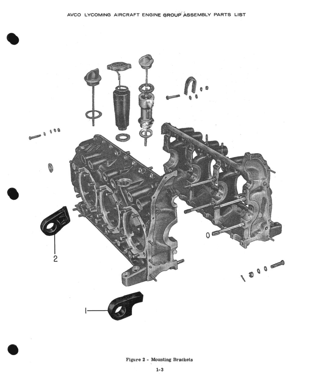
20 Figure 1 - Crankcase Assembly. l-2
21 GO-480-B, -D AND -F6 SERIES SECTION I (CONT.) ENGINE MOUNTING BRACKETS REF. PART DESCRIPTION PER NO. NUMBER ENG. USAGE USAGE BRACKET, Engine support, rear 2 A, C BRACKET, Engine support, front 2 A, C BRACKET, Engine mount, front 2 B BRACKET ASSEMBLY, Engine mount, rear 2 B STUD, 3/8-16 x 2-5/8 in. long 2 B STUD, 3/8-16 x 2-7/8 in. long 2 B BRACKET, Engine mount, front 2 * 8 STD-35 WASHER, Plain, 5/16 in. 6 * 9 STD-616 NUT, Self-locking 5/ * BRACKET ASSEMBLY, Engine mount, right rear 1 * 11 STD-1171 INSERT, Heli-coil, 3/8-16 x 3/4 in. long 2 * STUD, 3/8-16 x 2-3/4 in. long 2 * BRACKET ASSEMBLY, Engine mount, left rear 1 * 14 STD-33 WASHER, Plain, 3/8 in. 6 * 15 AN6-27A BOLT, Hex. hd., 3/8-24 x 2-61/64 in. long 2 * 16 STD-617 NUT, Self-locking, 3/ * * - Optional engine mountings for Beech installations only, not illustrated. 1-3
22
23 Figure 3 - Crankcase Related Parts
24
25 GO-480-B, -D AND -F6 SERIES SECTION I (CONT.) CRANKSHAFT ASSEMBLY REF. PART DESCRIPTION QTY. MODEL USAGE NO. NUMBER ENG CRANKSHAFT AND COUNTERWEIGHT ASSEMBLY 1 A CRANKSHAFT AND COUNTERWEIGHT ASSEMBLY 1 B CRANKSHAFT AND COUNTERWEIGHT ASSEMBLY 1 C BUSHING, Crankshaft, dynamic counterweight 12 A, B, C BUSHING, Crankshaft, front 1 A, B, C BUSHING, Rear crankshaft spline 1 B DOWEL, Rear crankshaft spline bushing 3 B COUNTERWEIGHT ASSEMBLY 6 A, B COUNTERWEIGHT ASSEMBLY 5 C COUNTERWEIGHT ASSEMBLY, Light 1 C ROLLER, Dynamic counterweight, 3rd order 12 A, B ROLLER, Dynamic counterweight, 3rd order 10 C ROLLER, Dynamic counterweight 2 C RING, Internal retaining 24 A, B, C WASHER, Dynamic counterweight 24 A, B, C 12 STD-858 KEY, Woodruff, special, 5/32 in. x 5/8 in. 1 A, B, C GEAR, Crankshaft timing 1 A, C GEAR, Crankshaft timing 1 B PLATE, Crankshaft gear, lock 1 A, C PLATE, Crankshaft gear, lock 1 B NUT, Crankshaft gear retaining 1 A, C NUT, Crankshaft gear retaining 1 B SHIM, 1-1/8 OD x 11/32 ID x in. thick AR A, C JAW, Starter 1 A, C LOCKPLATE, Starter jaw 1 A, C PIN, Starter jaw 1 A, C 20 STD-856 SCREW, Hex. hd., 5/16-24 x 15/16 in. long 1 A, C TUBE, Crankshaft oil, front 6 * TUBE, Crankshaft oil, end 1 * PLUG, Crankshaft oil, front 1 * * - These parts are being maintained in stock for crankshaft assemblies employing sludge tubes. 1-5
26 23 3 Figure 4 - Crankshaft Assembly l-5
27 GO-480-B, -D AND -F6 SERIES SECTION I (CONT. ) l-6 - CAMSHAFT ASSEMBLY CAMSHAFT ASSEMBLY CAMSHAFT ASSEMBLY C A,B, A,B, 1 A 1 B 1 4 A,B 4 2 A,B,C Figure 5 - Camshaft Assembly l-6
 1-7 - OIL LEVEL GAGE ASSEMBLIES 1 10457 GASKET, Oil filler extension A, C 2 68982 EXTENSION ASSEMBLY, Oil filler 1 A 69923 EXTENSION ASSEMBLY, oil filler 1 C 39 66942 EXTENSION.")
28 GO-460-B, -D AND - F6 SERIES SECTION I (CONT. ) OIL LEVEL GAGE ASSEMBLIES GASKET, Oil filler extension A, C EXTENSION ASSEMBLY, Oil filler 1 A EXTENSION ASSEMBLY, oil filler 1 C EXTENSION. Oil level gage 1 c GASKET, Oil filler plug i C GAGE ASSEMBLY. Oil level 1 C CAP ASSEMBLY, Oil filler CAP ASSEMBLY, Oil filler GAGE ASSEMBLY, Oil level 1 A.... Figure 6 - Oil Level Gage Assemblies l-l
29 GO-480-B, -D AND -F6 SERIES SECTION I (CONT.) CRANKCASE ATTACHING PARTS REF. PART DESCRIPTION MODEL MODEL NO. PER. USAGE NUMBER ENG.USAGE SEAL, Oil, 3/32 dia. section x 15/32 ID 8 A 2 AN6-16 BOLT, Hex. hd., drilled shank, 3/8-24 x 1-53/64 in. 1 A long 3 AN6-24 BOLT, Hex. hd., drilled shank, 3/8-24 x 2-37/64 in. 2 A long 4 AN6-21A BOLT, Hex. hd., 3/8-24 x 2-13/64 in. long 4 A 5 STD-33 WASHER, Plain, 3/8 in. 15 A 6 STD-872 NUT, Slotted, 3/ A 7 STD-713 PIN, 3/32 dia. x 3/4 in. long 1 A 8 STD-678 WASHER, Internal lock, 3/8 in. 4 A 9 STD-596 NUT, Plain, 3/ A STRAP, Lifting 2 A 11 AN4-15A BOLT, Hex. hd., 1/4-28 x 1-21/32 in. long 2 A 12 AN4-12A BOLT, Hex. hd., 1/4-28 x 1-9/32 in. long 5 A 13 AN4-16 BOLT, Hex. hd., 1/4-28 x 1-25/32 in. long 6 A 14 STD-8 WASHER, Plain, 1/4 in. 26 A 15 STD-160 WASHER, Internal lock, 1/4 in. 7 A 16 STD-9 NUT, Plain, 1/ A 17 STD-97 NUT, Slotted, 1/ A 1-8
30
31
32 AVCO LYCOMING PARTS CATALOG GO-480-B, -D AND -F6 SERIES SECTION II REDUCTION GEAR ASSEMBLY
33
34 Reduction Gear Assembly Reduction Gear Assembly Stationary Gear Pinion Cage Stationary Gear Pinion Cage Propeller Shaft Thrust Bearing Propeller Shaft, Thrust Bearing Governor Drives and Adapter Engine (Spline) (Flange) (Spline) (Flange) (Spline) (Flange) (Both) Model GO-480-B A, B A, B A, B A GO-480-B1A6 A, B A, B A, B A GO-480-B1B A, B A, B A, B A GO-480-B1C A, B A, B A, B A GO-480-B1D A, B A, B A, B A GO-480-D1A B A, B A, B B GO-480- F6 C C C C GO-480- F1A6 C C C C GO-480-F2A6 B A, B A, B B GO-480-F4A6 C C D* C AVCO LYCOMING PARTS CATALOG GO-480-B, -D AND -F6 SERIES SECTION II REDUCTION GEAR ASSEMBLY Page Numbers * - Propeller Shaft used for installation of Hartzell propeller.
35 GO-480-B, -D AND -F6 SERIES SECTION II REDUCTION GEAR ASSEMBLY (SPLINE TYPE) REF. PART MODEL REF. PART DESCRIPTION PER MODEL NO. NUMBER ENG. USAGE GASKET, Reduction gear housing, Not Ill. 1 A, B 2 STD-994 RING, Oil seal, 1/2 in. ID x 3/32 dia., Not Ill. 1 A, B GEAR ASSEMBLY, Reduction 1 A GEAR ASSEMBLY, Reduction 1 B See note GEAR ASSEMBLY, Ring, Not Ill. 1 A, B GEAR, Ring 1 A, B PLATE, Ring gear drive 1 A, B CIRCLIP, Ring gear AR A, B CIRCLIP, Ring gear AR A, B CIRCLIP, Ring gear AR A, B LOCKRING, Gear circlip 1 A, B 9 STD-1017 RIVET, 3/32 dia. x 3/8 in. long 1 A, B HOUSING ASSEMBLY, Reduction gear and gov. 1 A, B HOUSING, Reduction gear and governor 1 A, B SLEEVE, Reduction gear housing 1 A, B 13 STD-798 DOWEL, 3/32 dia. x 9/32 in. long 1 A, B STUD, 3/8-16 x 2-1/8 in. long 6 A, B PLUG, Alien head, 1/8-27 NPT 1 A, B 16 STD-1021 DOWEL, 3/16 dia. x 5/8 in. long 1 A, B STUD, 1/4-20 x 1-1/4 in. long 6 A, B 18 STD-1736 PIN, dia. x 23/64 in. long 1 A, B BUSHING, Governor drive, rear 1 A, B BUSHING, Governor drive, front 1 A, B NOTE Above parts marked B are also applicable to GO F2A6. 2-2
36
37 GO-480-B, -D AND -F6 SERIES SECTION II (CONT.) REDUCTION GEAR ASSEMBLY (FLANGED TYPE) REF. PART DESCRIPTION PER MODEL NO. NUMBER ENG.USAGE GASKET, Reduction gear housing 1 C 2 STD-994 RING, Oil seal, 1/2 in. OD x 3/32 in. dia. 1 C GEAR ASSEMBLY, Reduction 1 C* GEAR ASSEMBLY, Ring 1 C GEAR, Ring 1 C PLATE, Ring gear drive 1 C CIRCLIP, Ring gear AR C CIRCLIP, Ring gear AR C CIRCLIP, Ring gear AR C LOCKRING, Gear circlip 1 C 9 STD-1017 RIVET, 3/32 in. dia. x 3/8 in. long 1 C HOUSING ASSEMBLY, Reduction gear and governor 1 C SLEEVE, Reduction gear housing 1 C 12 STD-859 DOWEL, 1/8 in. dia. x 9/32 in. long 1 C STUD, 5/16-18 x 1-29/64 in. long 4 C** STUD, 3/8-16 x 2-1/8 in. long 6 C STUD, 1/4-20 x 1-1/4 in. long 6 C 16 STD-1021 DOWEL, 3/16 dia. x 5/8 in. long 1 C PLUG, Allen, 1/8-27 NPT 1 C 18 STD-1736 PIN,. 158 to. 159 dia. x 3/8 in. long 1 C DOWEL, Stationary gear drive plate 2 C** BUSHING, Governor drive, rear 1 C BUSHING, Governor drive, front 1 C * - Reduction gear assemblies, and 74511, which incorporate body fit bolts are available from Avco Lycoming. Consult Avco Lycoming Service Instruction No for full details. ** - Parts marked in this manner are eliminated when body fit bolts are used. 2-3
38
39 GO-480-B, -D AND -F6 SERIES SECTION II (CONT.) STATIONARY GEAR AND PINION CAGE (SPLINE PROPELLER SHAFT) REF. PART DESCRIPTION QTY. MODEL NO. NUMBER USAGE ENG GEAR ASSEMBLY, Stationary 1 A, B See note GEAR, Stationary 1 A, B PLATE, Stationary gear drive 1 A, B CIRCLIP, Stationary gear AR A, B CIRCLIP, Stationary gear AR A, B CIRCLIP, Stationary gear AR A, B CIRCLIP, Stationary gear AR A, B 5 STD-35 WASHER, Plain, 5/16 in. 4 A, B BOLT, Stationary gear drive plate 4 A, B 7 STD NUT, Castle, 5/ A, B 8 STD-68 PIN, Cotter, 1/16 x 1/2 in. long 4 A, B CAGE ASSEMBLY, Pinion 1 A, B CAGE, Pinion 1 A, B SHAFT, Pinion 6 A, B CUP, Pinion shaft, oil retaining 6 A, B PIN, Pinion shaft 6 A, B ROLLER, Pinion 102 A, B SPACER, Pinion roller 12 A, B GEAR, Pinion 6 A, B GASKET, Housing oil retaining 1 A, B HOUSING, Oil retaining 1 A, B 19 STD SCREW, Fill. hd., drilled, 1/4-28 x 3/8 in. long 6 A, B NOTE All above parts are applicable to GO-480-F2A6 model engines. 2-4
40 AVCO LYCOMlNG AIRCRAFT ENGINE GROUP ASSEMBLY PARTS LIST l Figure 10 - Statinary Gear and Pinion Cage Ass'y. (Spline Type) a4
41 GO-480-B, -D AND -F6 SERIES SECTION II (CONT.) STATIONARY GEAR AND PINION CAGE (FLANGED PROPELLER SHAFT) QTY. REF. PART DESCRIPTION PER MODEL NO. NUMBER ENG. USAGE GEAR ASSEMBLY, Stationary 1 C* GEAR, Stationary 1 C PLATE, Stationary gear drive 1 C CIRCLIP, Stationary gear AR C CIRCLIP, Stationary gear AR C CIRCLIP, Stationary gear AR C CIRCLIP, Stationary gear AR C 5 STD-1013 NUT, Castle, 5/16 in. 4 C CAGE ASSEMBLY, Pinion 1 C* CAGE, Pinion 1 C SHAFT, Pinion 6 C CUP, Pinion shaft oil retaining 6 C PIN, Pinion shaft 6 C ROLLER, Pinion 102 C SPACER, Pinion roller 12 C GEAR, Pinion 6 C GASKET, Housing oil retaining 1 C HOUSING, Oil retaining 1 C 16 STD-1016 SCREW, Fill. hd., drilled, 1/4-28 x 3/8 in. long 6 C * - Not illustrated. 2-5
42
43 GO-466-B, -D AND -F6 SERIES SECTION If (CONT.) PROPELLER SHAFT AND THRUST BEARING (SPLINE PROPELLER SHAFT) STD STD STD SHAFT, Propeller LOCKPLATE, Pinion cage nut, Fig. 6, Page 2-2 NUT, Pinion cage retaining, FIG. 6, Page 2-2 KEY, Woodruff, 1/6 x 1/2 in. GEAR, Governor drive SLEEVE, Propeller shaft seal RING, Propeller shaft seal BEARlNG, Thrust SLINGER, Thrust bearing oil SHIM, Thrust bearing cap CAP ASSEMBLY, Thrust bearing CAP, Thrust bearing SEAL, Thrust bearing WASHER, Plain, 3/8 in. SPACER, Thrust bearing cap nut NUT, Thin, self-locking, 3/ A, B See note 6 A, B NOTE All parts listed above are applicable to GO-460- F2A6 model engines. Figure 12 - Propeller shaft and Thrust Bearing cap (Spline Type) 2-6
44 GO-460-B. -D AND -F6 SERIES SECTION II (CONT. ) STD STD-1392 STD STD STD-33 STD-1695 SHAFT ASSEMBLY, Propeller SHAFT ASSEMBLY, Propeller SHAFT, Propeller TUBE ASSEMBLY, Prop. shaft oil transfer PLUG, Slotted, 5/16-18 x 5/16 in. long PLUG, Prop. shaft oil transfer PLUG..266 to.269 dia. x 5/16 tn. long PIN, 1/8 in. dia x9/16 in. long LOCKPLATE, Pinion cage nut NUT, Pinion cage KEY, Woodruff, l/s x l/2 in. GEAR, Governor drive SLEEVE, Prop. shaft seal RING, Prop. shaft seal BEARING, Thrust SLINGER, Thrust bearing oil SHIM, Thrust bearing cap CAP ASSEMBLY, Thrust bearing CAP, Thrust bearing SEAL, 2-7/a ID x 4.OO in OD x 15/22 SPACER, Thrust bearing cap nut WASHER, Plain, 3/8 in. NUT, Thin, self-locking 1: 1 2 1: 1: 1 1: 12 1: Figure 13 - Propeller Shaft and Thrust Bearing Cap (Flange Type) 2-7
45 GO-480-B, -D AND -F6 SERIES SECTION II (CONT.) GOVERNOR DRIVES AND GOVERNOR DRIVE ADAPTER (SPLINE AND FLANGED PROP. SHAFT) QTY. REF. PART DESCRIPTION PER MODEL NO. NUMBER ENG.USAGE USAGE GEAR ASSEMBLY, Governor drive idler 1 A, B, C BUSHING, Governor drive idler 1 A, B, C BUSHING, Governor drive idler, thrust 1 A, B, C 4 STD-798 DOWEL, 3/32 in. x 9/32 in. long 2 A, B, C WASHER, Governor drive idler thrust AR A, B, C WASHER, Governor drive idler thrust AR A, B, C WASHER, Governor drive idler thrust AR A, B, C SHAFT ASSEMBLY, Governor drive idler 1 A, B, C SHAFT, Governor drive idler 1 A, B, C* 10 STD- 120 PLUG, Slotted 5/16-18 x 5/16 in. long 1 A, B, C GASKET, Governor drive adapter 2 A, B, C SHIM, Governor drive adapter 1 A, B, C ADAPTER ASSEMBLY, Governor drive A ADAPTER ASSEMBLY, Governor drive 1 B ADAPTER ASSEMBLY, Governor drive 1 C PLUG, Allen, 1/8-27 NPT 3 A, B 1102 PLUG, Allen, 1/8-27 NPT 5 C BUSHING, Governor drive adapter 1 A, B, C 16 STD- 394 DOWEL, 3/32 in. x 11/32 in. long 1 A, B, C STUD, 5/16-18 x 1-7/8 in. long 4 A STUD, 5/16-18 x 2-1/4 in; long 4 B, C GEAR, Governor driven 1 A, B, C 19 STD-332 CIRCLIP, 13/16 ID x 3/64 dia. wire 1 A, B, C GASKET, Governor drive 1 A, B, C COVER, Governor drive 1 A, B, C 22 STD-35 WASHER, Plain, 5/16 in. 4 A STD-35 WASHER, Plain, 5/16 in. 16 B,C 23 STD-475 WASHER, Internal lock, 5/16 in. 4 A, B, C 24 STD-37 NUT, Plain, 5/16-24 NF-3 4 A, B, C 25 STD-8 WASHER, Plain, 1/4 in. 6 A, B, C 26 STD- 160 WASHER, Internal lock, 1/4 in. 6 A, B, C 27 STD-9 NUT, Plain, 1/4-28 NF-3 6 A, B, C 28 STD-111 GASKET, 1.00 ID x 1-1/4 OD x 3/32 in. annular 1 A, B, C PLUG, 5/8 in. hex. hd., x thread 1 A, B, C PIN, Engine timing 1 A, B, C 31 STD-33 WASHER, Plain, 3/8 in. 8 A, B, C 32 STD-678 WASHER, Internal lock, 3/8 in. 8 A, B, C 33 STD- 596 NUT, Plain, 3/ A, B, C BOLT, Crankshaft flange, Fig. 8, Page A, B, C NUT, Crimp, 3/8-24, Fig. 8, Page A, B, C PLATE, Name 1 A, B, C 37 STD DRIVE STUD, #4 x 3/16 in. round head 4 A, B, C 2-8
46 Figure 14 - Governor Drives and Governor Drive Adapter (Spline and Flange Type) 2-S
47
48 AVCO LYCOMING PARTS CATALOG GO-480-B, -D AND -F6 SERIES SECTION III ACCESSORY HOUSING ASSEMBLY
49
50 Gear Train Oil Acc'y. Hsg. and Acc'y. Magneto Dr. Tach. Acc'y. Hsg. Accessory Starter Oil Pump Scavenge Acc'y. Hsg. Main Acc'y. Assembly Hsg. Group & Gr. Train Drives Assembly Dr. Gears Dr. Ass'y. Drive Pump Dr. Cover Acc'y. Dr. Covers Acc'y. Hsg. Rr. Mtd. Rr. Mtd. Rr. Mtd. SAE Crosswise Crosswise Crosswise Crosswise Crosswise Crosswise Crosswise and Attaching Engine. Accy's. Accy's. Accy's. andan Accy's. Accy's. Accy's. Accy's Accy's. Accy's Accy's. Gaskets Parts Model GO-480-B A,B A, B A,B A,B A, C A GO-480-B1A6 A, B A,B A, B A,B A, C A GO-480-BIB E E E E A, C C GO-480-B1C C,D C,D C, D C, D A, C B GO-480-BD G G G G A, C B GO-480-D1A J J J J J J J B E GO-480-F6 E,F E, F E, F E, F A,C D GO-480-F1A6 H H H H A, C D GO-480-F2A6 H H H H A, C D GO-480- F4A6 H H H H A, C D AVCO LYCOMING PARTS CATALOG GO-480-B, -D AND -F6 SERIES SECTION III ACCESSORY HOUSING ASSEMBLIES Page Numbers
51 GO-480-B, -D AND -F6 SERIES SECTION III ACCESSORY HOUSING ASSEMBLY (REAR MOUNTED ACCESSORIES) REF PART MODEL REF. PART DESCRIPTION MODEL NO. NUMBER ENG. USAGE GASKET, Accessory housing, not illustrated 1 A, B, C, D, E, F, G, H HOUSING ASSEMBLY, Accessory (SAE-Drive) 1 A HOUSING ASSEMBLY, Accessory (AN-Drive) 1 B HOUSING ASSEMBLY, Accessory (SAE-Drive) 1 C HOUSING ASSEMBLY, Accessory (AN-Drive) 1 D HOUSING ASSEMBLY, Accessory (SAE-Drive) 1 E HOUSING ASSEMBLY, Accessory (AN-Drive) 1 F HOUSING ASSEMBLY, Accessory (SAE-Drive) 1 G HOUSING ASSEMBLY, Accessory (AN-Drive) 1 H 3 STD-1315 INSERT, Heli-coil, 1/4-28 x 1/2 in. long 4 A, B, C, D, E, F, G, H STUD, 3/8-16 x 1-3/4 in. long 6 A, B, E, F, G, H STUD, 3/8-16 x 1-3/4 in. long 4 C, D 5 31D-16 STUD, Drilled, 5/16-18 x 2.00 in. long 2 A, B, C, D, E, F, G STUD, 3/8-16 x 3-1/2 in. long 2 C, D 7 31D-19 STUD, Drilled, 5/16-18 x 2-3/8 in. long 1 A, B, C, D, E, F, G, H STUD, 5/16-18 x 1-5/8 in. long 14 A, B, C, D, G, H STUD, 5/16-18 x 1-5/8 in. long 10 E, F STUD, 5/16-18 x 2.00 in. long 2 E, F STUD, 1/4-20 x 1-1/2 in. long 7 A, C, E, G STUD, 1/4-20 x 1-1/2 in. long 4 B, D, F, H STUD, 1/4-20 x 1-5/8 in. long 2 B,D, F, H STUD, 1/4-20 x 1-3/8 in. long, Not Ill. 2 E, F BUSHING, 1-1/4 OD x 1-1/8 ID x 1-19/64 in. long 1 A, B BUSHING, 1-1/4 OD x 1-1/8 ID x 1-7/16 in. long 1 C, D, E, F, G, H STD-798 DOWEL, 3/32 in. dia. x 9/32 in. long 1 A, B STD- 151 DOWEL, 1/8 in. dia. x 1/4 in. long, Not Ill. 1 C, D, E, F, G, H PLUG, Socket, 1/8 pipe x 3/8 in. long 2 A, B, C, D, E, F, G, H 16 STD-453 PLUG, Square head, drilled, 3/8 pipe 2 A, B, C, D, E, F, G, H 17 STD PLUG, Allen, drilled, 1/8-27 NPT 1 A, B, C, D, E, F, G, H ANNULUS, Oil seal 1 A, B BUSHING, Generator drive gear thrust 1 C, D 20 STD DOWEL, 1/8 in. dia. x 9/32 in. long, Not Ill. 1 C, D, E, F, G, H TUBE, Breather 1 A, B, C, D, E, F, G, H SUPPORT, Magneto drive bearing 2 A, B, C, D, F, G, H 23 STD-314 SCREW, Flat head, #10-32 x 7/16 in. long 2 A, B, C, D, F, G, H GEAR ASSEMBLY, Tachometer (See fig. 18) 1 A, C, E, G COVER ASSEMBLY, Tachometer (See fig. 18) 1 A, C, E, G COVER, Breather, Not Ill. 1 C, D, E, F, G, H 27 STD SCREW, Fill. hd., drilled, 5/16-18 x 7/8 in. long, Not Ill. 1 C, D, E, F, G, H 28 STD-911 SEAL, 1-63/64 OD x 1-1/8 ID x 7/32 in. thick 1 E, G, H 3-2
52
53 GO-480-B, -D AND -F6 SERIES SECTION III (CONT.) GEAR TRAIN AND ACCESSORY HOUSING GROUP (REAR MOUNTED ACCESSORIES) QTY. MODEL REF. PART DESCRIPTION PER NO. NUMBER ENG. USAGE USAGE GEAR, Camshaft 1 A, B GEAR, Camshaft 1 C, D, E, F, G, H GEAR, Generator drive 1 C, D, E, F, G, H 3 STD-679 SCREW, Hex. hd., 5/16-24 x 27/64 in. long 4 A, B STD-703 SCREW, Hex. hd., 5/16-24 x 37/64 in. long 4 C, D, E, F, G, H LOCKPLATE, 5/16 bolt x 1-21/64 in. spacing 2 A, B, C, D, E, F, G, H GEAR, Tachometer drive 1 A, B, C, D, E, F, G, H GEAR, Oil pump drive 1 A, B, C, D, E, F, G, H IMPELLER, Oil pump, driving 1 A, B, C, D, E, F, G, H BODY ASSEMBLY, Oil pump 1 A, B, C, D, E, F, G, H 9 STD-35 WASHER, Plain, 5/16 in. 3 A, B, C, D, E, F, G, H 10 STD-2 NUT, Slotted, 5/ A, B, C, D, E, F, G, H BODY, Oil pump 1 A, B, C, D, E, F, G, H SHAFT, Oil pump idler 1 A, B, C, D, E, F, G, H 13 STD-714 PIN, Cotter, 1/8 in. dia. x 1.00 in. long 1 A, B, C, D, E, F, G, H IMPELLER, Oil pump, driven 1 A, B, C, D, E, F, G, H GEAR ASSEMBLY, Generator driven 1 A, B GEAR ASSEMBLY, Generator driven 1 C, D, E, F, G, H SPACER, Generator gear retaining plate 2 A, B SPACER, Generator gear retaining plate 2 C, D, E, F, G, H PLATE, Retaining, generator gear, driven 1 A, B PLATE, Retaining, generator gear, driven 1 C, D, E, F, G, H 18 STD- 395 SCREW, Hex. hd., dr. hd., 1/4-20 x 1-1/4 in. long 2 A, B STD SCREW, Hex. hd., dr. hd., 1/4-20 x 1-1/2 in. long 2 C, D, E, F, G, H GEAR ASSEMBLY, Generator drive, idler 1 A, B BUSHING, 1.00 ID x 1-1/8 OD x 7/8 in. long 21 STD-798 DOWEL, 3/32 in. dia. x 9/32 in. long 1 1 A, B A, B COUNTERSHAFT, Generator drive 1 A, B SHIELD, Oil, gen. drive countershaft 1 A, B 24 STD-1354 WASHER, Plain, 5/16 in. 1 A, B SCREW, Socket hd., 5/16-24 NF-3 x 2-5/8 in. long 1 A, B NUT, Gear retaining 1 A, B 27 STD-68 PIN, Cotter, 1/16 in. dia. x 1/2 in. long 1 A, B 3-3
54 AVCO LYCOMINS AIRCRAFT ENGINE GROUP ASSEMBLY PARTS LIST (Rear Mounted Accessories) 3-3
55 GO-480-B, -D AND -F6 SERIES SECTION III (CONT.) GEAR TRAIN (CONT.) MAGNETO DRIVES (REAR MOUNTED ACCESSORIES) REF. PART DESCRIPTION QTY. MODEL NO. NUMBER ENG.USAGE BEARING, Magneto drive 2 A, B, C, D, G, H GEAR ASSEMBLY, Magneto 2 A, B, C, D, G, H RETAINER, Magneto drive cushion 2 A, B, C, D, G, H CUSHION, Magneto drive 4 A, B, C, D, G, H 5 STD-208 SEAL, Oil, 7/8 ID x 1-1/2 OD x 5/16 in. wide 1 A, B, E, F, G, H VACUUM PUMP DRIVE GEAR ASSEMBLY, Vacuum pump drive 1 A, B, C, D, E, F, G, H 7 STD-213 SEAL, Oil, 1-3/8 OD x 3/4 ID x 5/16 in. wide 1 A, B, C, D, E, F, G, H FUEL PUMP DRIVE GEAR ASSEMBLY, Fuel pump drive 1 A, B, C, D, E, F, G, H GEAR, Crankshaft timing 1 A, B, C, D, E, F, G, H GENERATOR DRIVE GASKET, Generator housing 2 C,D SHIM, Generator housing 1 C,D GEAR ASSEMBLY, Generator drive 1 C, D GEAR ASSEMBLY, Generator driven 1 C, D HOUSING ASSEMBLY, Generator 1 C, D BUSHING, 1-1/4 OD x 1-1/8 ID x 7/8 in. long 1 C, D BUSHING, 1-1/4 OD x 1-1/8 ID x 1-19/64 in. long 1 C, D ANNULUS, Oil seal 1 C, D 18 STD-798 DOWEL, 3/32 dia. x 9/32 in. long 2 C, D 19 STD- 119 PLUG, Straight, dia. x 1/4 in. long 1 C, D STUD, 1/4-20 x 1-1/2 in. long 4 C,D STUD, 3/8-16 x 1-7/8 in. long 6 C,D 22 STD-208 SEAL, Oil, 7/8 ID x 1-1/2 OD x 5/6 in. wide 2 C, D 3-4
56 5 I Figure 17 - Magneto Drives (Rear Mounted Accesseories)
57 GO-480-B, -D AND -F6 SERIES SECTION III (CONT.) TACHOMETER DRIVES, SAE AND AN REF. PART DESCRIPTION QTY. PER MODEL NO. NUMBER ENG. USAGE USAGE ADAPTER ASSEMBLY, Tachometer 1 B, D, F, H 2 STD-8 WASHER, Plain, 1/4 in. 6 B, D, F, H 3 STD-160 WASHER, Internal lock, 1/4 in. 4 B, D, F, H 4 AN4-11A BOLT, Hex. hd., 1/4-28 x 1-5/32 in. long 2 B, D, F, H 5 STD-9 NUT, Plain, 1/ B, D, F, H STUD, 1/4-20 x 1-3/8 in. long 4 B, D, F, H 7 STD- 547 SEAL, Oil, 9/16 ID x 1-1/4 in. OD x 5/16 in. wide 1 B, D, F, H SHAFT, Tachometer idler gear 1 B, D, F, H 9 STD-714 PIN, Cotter, 1/8 dia. x 1.00 in. long 1 B, D, F, H GASKET, Tachometer adapter 1 B, D, F, H SUPPORT, Tachometer adapter 1 B, D, F, H 12 STD- 197 SCREW, Flat head, 1/4-20 x 7/8 in. long 1 B, D, F, H GASKET, Tachometer cover 1 B, D, F, H GEAR ASSEMBLY, Tachometer idler 1 B, D, F, H GEAR ASSEMBLY, Tachometer driven 1 B, D, F, H COVER, Vacuum pump (Not Illustrated) 1 B, D, F, H GASKET, Vacuum pump (Not Illustrated) 1 B, D, F, H STUD, 1/4-20 x 1-5/8 in. long 2 B,D, F, H SEAL, Tachometer shaft 1 A, C, E, G COVER ASSEMBLY, Tachometer 1 A, C, E, G 21 STD-8 WASHER, Plain, 1/4 in. 3 A, C, E, G 22 STD- 160 WASHER, Internal lock, 1/4 in. 3 A, C, E, G 23 STD-9 NUT, Plain, 1/ A, C, E, G GEAR ASSEMBLY, Tachometer 1 A, C, E, G GASKET, Tachometer cover 1 A, C, E, G STUD, 1/4-20 x 1-1/2 in. long 3 A, C, E, G 3-5
58 I
59 GO-480-B, -D AND -F6 SERIES SECTION III (CONT.) ACCESSORY HOUSING ASSEMBLY (CROSSWISE ACCESSORY MODELS) REF. PART DESCRIPTION QTY. MODEL PER NO. NUMBER ENG. USAGE GASKET, Accessory housing 1 J HOUSING ASSEMBLY, Accessory 1 J 3 STD-1315 INSERT, Heli-coil, 1/4-28 x 1/2 in. long 5 J BUSHING, 1-3/16 OD x 1.00 ID x 1.00 in. long 1 J DOWEL, 1/4 in. dia. x 1/2 in. long 2 J BUSHING, 1-7/8 in. OD x 1-11/16 ID x 3/4 in. long 1 J 7 STD-859 DOWEL, 1/8 dia. x 9/32 in. long 1 J BUSHING, 1-1/16 OD x 7/8 ID x 1-7/32 in. long 1 J PLUG, Allen, 1/8-27 NPT. 1 J 10 25D-11 STUD, 1/4-20 x 1-3/8 in. long, drilled 8 J STUD, 1/4-20 x 1-1/2 in. long 13 J STUD, 1/4-20 x 1-5/8 in. long 15 J STUD, 1/4-20 x 5.00 in. long 1 J STUD, 1/4-20 x 3-3/8 in. long 1 J STUD, 1/4-20 x 4-1/4 in. long 2 J STUD, 1/4-20 x 2.00 in. long 4 J STUD, 1/4-20 x 2-7/8 in. long 1 J STUD, 1/4-20 x 4-5/8 in. long 1 J 19 25D-24 STUD, 1/4-20 x 3.00 in. long, drilled 1 J STUD, 5/16-18 x 1-3/4 in. long 6 J STUD, 5/16-18 x 3-1/4 in. long 1 J STUD, 5/16-18 x 2-5/8 in. long 1 J STUD, 3/8-16 x 2.00 in. long 6 J ANNULUS, Oil seal 1 J PIN, Timing 1 J 26 STD-1339 PLUG, Allen, 1/16-27 NPT. 5 J 27 STD-111 GASKET, 1.00 ID x 1-1/4 OD x 3/32 annular 1 J 28 STD-71 PLUG, Allen, 3/8 in. pipe 2 J PLUG, 5/8 in. hex. hd., THD. 1 J PLUG, 41/64 in. dia. x 3/16 in. long 1 J 3-6
60 AVCO LYCOMINS AIRCRAFT ENGINE GROUP ASSEMBLY PARTS LIST Figure 19 - Accessory Housing Assembly (Crosswise) 3-6
61 GO-480-B, -D AND -F6 SERIES SECTION III (CONT.) ACCESSORY DRIVE GEARS (CROSSWISE ACCESSORY MODELS) NO. NUMBER ENG.USAGE STD-213 SHAFTGEAR ASSEMBLY, Fuel pump drive SEAL, Oil, 3/4 in. ID x 1-3/8 in. OD x 5/16 in. wide 1 1 J J SHAFTGEAR ASSEMBLY, Vacuum pump 1 J 4 STD-1708 SEAL, 1-7/16 OD x 1.00 ID x 25/64 in. wide 1 J WASHER, Generator drive gear thrust 1 J SHAFTGEAR ASSEMBLY, Generator drive 1 J SHAFT, Magneto drive idler 1 J 8 STD-1854 SEAL, Washer, 5/16 in. 1 J 9 STD-1860 SCREW, Flat fill. hd., drilled shank, 5/16-24 x 1 J 3-1/8 in. long 10 STD-2 NUT, Slotted, 5/ J 11 AN PIN, Cotter, 1/16 in. dia. x 5/8 in. long 1 J WASHER ASSEMBLY, Magneto drive idler shaft 1 J HUB ASSEMBLY, Magneto drive idler 1 J BUSHING, Magneto drive idler gear 1 J STD-19 DOWEL, 3/32 in. dia. x 7/32 in. long 1 J SLINGER, Oil 1 J GEAR, Magneto drive idler 1 J 17 AN BOLT, Drilled end, 1/4-28 x 3/4 in. long 4 J 18 STD-43 NUT, Slotted shear, 1/ J GEAR ASSEMBLY, Tachometer driven 1 J 20 STD-547 SEAL, 9/16 ID x 1-1/4 OD x 5/16 wide 1 J GEAR ASSEMBLY, Starter drive, not ill. 1 J GEAR, Starter drive 1 J GEAR, Accessory drive 1 J DOWEL, 1/4 dia. x 7/16 in. long, hollow pin 3 J 25 AN SCREW, Fill. hd., drilled, 1/4-28 x 1/2 in. long 6 J SHAFT ASSEMBLY, Magneto drive 1 J SLEEVE, Magneto drive shaft 1 J GEAR, Magneto drive shaft 1 J WASHER, Magneto drive shaft gear 1 J RING, Retaining, magneto drive gear 1 J 3-7
62 l Figure 20 - Accessory Drive Gears (Crosswise Acc y. ) 3-7
63 GO-480-B, -D AND -F6 SERIES SECTION III (CONT. ) STARTER DRIVE ASSEMBLY (CROSSWISE ACCESSORY MODELS) ADAPTER ASSEMBLY, Starter drive BUSHING, 1-11/16 OD x 1-1/2 ID x 1.66 in. long STD-394 DOWEL, 3/32 dia. x 11/32 in. long BUSHING. 1-11/16 OD x 1-1/2 ID x 1.66 in. low STD-6 STD-696 STD-97 STD STD WASHER, Plain, 1/4 in WASHER, 17/64 ID x 1/2 in OD x 1/32 in. thick NUT, Slotted, 1/4-26 SEAL, Oil, 2-5/8 OD x 1-13/16 ID x l/2 in wide JAW, Starter CIRCLIP, 1-S/32 x 5/64 dia. wire GASKET, Starter drive pad ADAPTER, Starter 1 J 2 3 J 1 J AR J 6 J 1: J 1 J 1 3-6
64
65 AVCO LYCOMING AIRCRAFT ENGINE GROUP ASSEMBLY PARTS LIST GO-480-B, -D AND -F6 SERIES SECTION III (CONT.) OIL PUMP DRIVE (CROSSWISE ACCESSORY MODELS) REF. PART DESCRIPTION PER NO. NUMBER ENG.USAGE GASKET, Hydraulic and oil pump adapter 1 J PUMP ASSEMBLY, Oil 1 J BODY ASSEMBLY, Oil pressure pump 1 J B BALL, 11/16 in. dia. 1 J BODY, Oil pressure pump 1 J RETAINER, Ball, check valve 1 J BUSHING, Oil pump drive shaft 1 J B SPRING, Check valve 1 J 9 STD-394 DOWEL,.0709 in. dia. x 11/32 in. long 1 J 10 25D-23 STUD, Drilled, 1/4-20 x 2-7/8 in. long 4 J 11 STD-1392 PLUG,.268 to.269 dia. x 5/16 in. long 1 J 12 25D-24 STUD, Drilled, 1/4-20 x 3.00 in. long 1 J 13 25D-26 STUD, Drilled, 1/4-20 x 3-1/4 in. long 1 J 14 MS INSERT, Heli-coil, #10-24 x 31/64 in. long 4 J 15 STD-1164 INSERT, Heli-coil, 5/16-18 x 5/8 in. long 1 J SLEEVE, Oil relief valve 1 J STUD, 5/16-18 x 1-1/2 in. long 1 J STUD, 5/16-18 x 1-3/4 in. long 3 J DOWEL, Oil pump 2 J SHAFT, Hydraulic pump or oil pump 1 J 21 STD-1973 KEY, Woodruff, 1/8 in. x 3/4 in. dia. 1 J IMPELLER, Oil pressure pump driving 1 J IMPELLER, Oil pressure pump driven 1 J 3-9
66
67 GO-480-B, -D AND -F6 SERIES SECTION III (CONT.) OIL SCAVENGE PUMP DRIVE (CROSSWISE ACCESSORY MODELS) REF. PART DESCRIPTION MODEL PER USAGE NO. NUMBER ENG SPACER, Oil pressure and oil scavenge pump 1 J IMPELLER, Oil scavenge pump, driving 1 J IMPELLER, Oil scavenge pump, driven 2 J BODY ASSEMBLY, Oil scavenge pump 1 J BODY, Oil scavenge pump 1 J BUSHING, Oil pump drive shaft 1 J 7 STD-394 DOWEL, 3/32 in. dia. x 11/32 in. long 1 J SHAFT, Oil pump idler, long 1 J SHAFT, Oil pump idler, short 1 J 10 AN PIN, Cotter, 1/8 dia. x 1-1/4 in. long 1 J STRAINER, Oil scavenge pump 1 J 12 STD-8 WASHER, Plain, 1/4 in. 6 J 13 STD-71 PLUG, Allen, 3/8 in. pipe 1 J 14 STD-43 NUT, Slotted shear, 1/ J GEAR, Oil pressure and scavenge pump 1 J 16 STD-61 NUT, Slotted shear, 1/ J 17 STD-60 PIN, Cotter, 3/32 in. dia. x 1.00 in. long 1 J 18 STD-208 SEAL, Oil, 7/8 ID x 1-1/2 OD x 5/16 in. wide 1 J WASHER, Oil filter assembly 1 J FILTER ASSEMBLY, Oil 1 J 21 AN GASKET, 1-3/4 ID x 2.00 OD x 3/32 annular 1 J COVER, Oil filter 1 J PLUNGER, Oil relief 1 J SPRING, Oil pressure relief 1 J 25 STD-351 GASKET, 3/4 ID x 3/32 thick, annular 2 J 26 STD-662 NUT, Relief valve adjusting 1 J SCREW, Oil relief valve adjusting 1 J NUT, Oil relief crown 1 J 3-10
68
69 GO-480-B, -D AND -F6 SERIES SECTION III (CONT.) ACCESSORY HOUSING COVER (CROSSWISE ACCESSORY MODELS) REF. PART DESCRIPTION PER MODEL DESCRIPTION PER NO. NUMBER ENG. USAGE USAGE GASKET, Accessory housing cover 1 J COVER ASSEMBLY, Accessory housing 1 J BUSHING, 1-3/16 OD x 1.00 ID x 1-1/8 in. long 1 J 4 STD-951 DOWEL, 1/8 in. dia. x 7/16 in. long 1 J BUSHING, 1-3/16 OD x 1.00 ID x 1-3/16 in. long 1 J 6 STD-951 DOWEL, 1/8 in. dia. x 7/16 in. long 1 J STUD, 1/4-20 x 1-1/2 in. long 5 J 8 25D-16 STUD, Drilled, 1/4-20 x 2.00 in. long 6 J 9 STD-434 DOWEL, 1/8 dia. x 21/64 in. long 1 J STUD, 5/16-18 x 1-3/4 in. long 1 J STD-783 STUD, 3/8-16 x 3-7/8 in. long PLUG, Allen, 1/4-18 NPT. 6 1 J J 13 STD PLUG,.204 to.205 dia. x 5/16 in. long 1 J STUD, 1/4-20 x 3-23/64 in. long 1 J BUSHING, 1-1/2 ID x 1-11/16 OD x 45/64 in. long 1 J PLUG, Allen, 1/8-27 NPT. 2 J 17 STD-1104 PLUG, Square head, drilled, 3/4-14 NPT. 2 J 3-11
70
 3-12 - MAIN ACCESSORY DRIVES (CROSSWISE ACCESSORY MODELS) 87838 75026 STD-1315 STD-8 STD-97 68835 30311 14412 AN501A416-12 67642 67641 12437 69700 STD-8 STD-160 STD-9 SHIM, Accessory drive shaft")
71 GO-480-B, -D AND -F6 SERIES SECTION III (CONT. ) MAIN ACCESSORY DRIVES (CROSSWISE ACCESSORY MODELS) STD-1315 STD-8 STD AN501A STD-8 STD-160 STD-9 SHIM, Accessory drive shaft adapter ADAPTER ASSEMBLY, Accessory drive shaft INSERT, Heli-coil, 1/4-28 x 1/2 in, long WASHER, Plain, 1/4 in NUT, Slotted, 1/4-28 GEAR, Accessory idler drive BEARING, Accessory idler gear PLATE, Accessory drive shaft adapter SCREW, Fill hd., drilled, 1/4-28 x 3/4 in, long LOCKWASHER, Accessory drive shaft NUT, Accessory drive shaft GASKET, Supercharger housing COVER. Accessory housing (rear) WASHER, Plain, i/4 in. WASHER Internal lock. 1/4 in. NUT, Plain, 1/ J J 4: J 8 J 8 J 1 J 1 J J 1 J 1 J* 1 J* 11 J* 11 J* 11 J* 6 Figure 25 - Main Accessory Drives (Crosswise Acc'y. Engines) 3-12
72
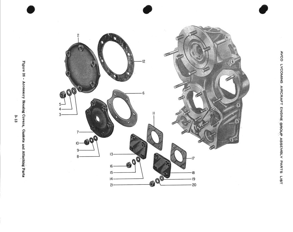
73 GO-480-B, -D AND -F6 SERIES SECTION III (CONT.) ACCESSORY COVERS, GASKETS AND ATTACHING PARTS QTY. REF. PART DESCRIPTION PER MODEL NO. NUMBER ENG.USAGE 1 AN GASKET, Accessory drive 2 B See note B COVER, Starter and generator 1 A, C 671-B COVER, Starter and generator 2 B 3 STD-33 WASHER, Plain, 3/8 in. 6 A, C 4 STD-678 WASHER, Internal lock, 3/8 in. 6 A, C 5 STD-596 NUT, Plain, 3/8 in. 6 A, C STD-33 WASHER, Plain, 3/8 in. 12 B STD-678 WASHER, Internal lock, 3/8 in. 12 B STD-596 NUT, Plain, 3/8 in. 12 B GASKET, Starter 1 A, C COVER, Starter 1 A, C 8 STD-35 WASHER, Plain, 5/16 in. 6 A, C 9 STD-475 WASHER, Internal lock, 5/16 in. 6 A, C 10 STD-37 NUT, Plain, 5/ A, C GASKET, Vacuum pump 1 A, C 8313 GASKET, Vacuum pump 2 B C GASKET, Generator 1 A, C COVER, Vacuum pump 1 A, C COVER, Vacuum pump 2 B 14 STD-8 WASHER, Plain, 1/4 in. 4 A, C 15 STD-160 WASHER, Internal lock, 1/4 in. 4 A, C 16 STD-9 NUT, Plain, 1/ A, C STD-8 WASHER, Plain, 1/4 in. 8 B STD-160 WASHER, Internal lock, 1/4 in. 8 B STD-9 NUT, Plain, 1/ B C GASKET, Fuel pump 1 A, B, C COVER, Fuel pump 1 A, B, C 19 STD-35 WASHER, Plain, 5/16 in. 4 A, B, C 20 STD-475 WASHER, Internal lock, 5/16 in. 4 A, B, C 21 STD-37 NUT, Plain, 5/ A, B, C GASKET, Hydraulic pump 1 B COVER, Hydraulic pump 1 B 24 STD-35 WASHER, Plain, 5/16 in. 4 B 25 STD-475 WASHER, Internal lock, 5/16 in. 4 B 26 STD-37 NUT, Plain, 5/ B NOTE All parts above marked "B" are for crosswise accessory model engines, and are illustrated on crosswise housings. 3-13
74

75 GO-460-B, -D AND -F6 SERIES SECTION III (CONT. ) ACCESSORY HOUSING ATTACHING PARTS STD-8 WASHING Plain, 1/4in 16 A,B,C,D STD-8 WASHER, Plain, l/4 in. 13 STD-160 WASHER, Internal lock, 1/4 in 10 A,B STD-160 WASHER, Internal lock, 1/4 in. 12 C,D,E STD-1230 BOLT, Hex. hd., 1/4-28 x 1-9/32 in long 3 A,B,C,D STD-1230 BOLT, Hex. hd., 1/4-28 x 1-9/32 in. long STD-9 NUT, Plain, 1/428 STD-9 NUT, Plain, 1/4-28 STD-9 NUT. Plain, 1/4-28 AN4-17A BOLT, Hex. hd., 1/4-28 x 1-29/32 in. long 1 10 A,B 12 C, D 11 1 A,B,C,D STD-1879 BOLT, Hex hd., 1/4-28 x 2-3/32 in long 1 STD-97 NUT, Slotted, 1/ A,B STD-68 PIN, Cotter, 1/16 in dia. x 1/2 in long 2 A, B Figure 26A - Accessory. - Housing Attaching Parts 3-14
76 AVCO LYCOMING PARTS CATALOG GO-480-B, -D AND -F6 SERIES SECTION IV CYLINDER, PISTON AND VALVE TRAIN
77
78 Cylinder Head Connecting Piston and Shroud Tubes Oil Drain Intercylinder Rod Ring Cylinder Valves and and Push Rod Valve Rocker Tube Baffle Engine Assembly Assembly Assembly Valve Springs Assemblies Assembly Assemblies Exhaust Flanges Assemblies Model GO-480-B A A A, B A A A A A, B A GO-480-B1A6 D A A, B A A A A A, B A GO-480-B1B B A A A A A A A, B A GO-480-B1C B A A, B A A A A A, B A GO-480-B1D B A A,B A A A A A,B A GO-480-D1A F A E, F B B B B C B GO-480-F6 E A C, D C C C C C C GO-480-F1A6 E A C,D C C C C C C GO-480-F2A6 E A C,D C C C C C C GO-480-F4A6 E A C, D C C C C C C AVCO LYCOMING PARTS CATALOG GO-480-B, -D AND -F6 SERIES SECTION IV CYLINDER, PISTON AND VALVE TRAIN Page Numbers
79 GO-460-B, -D AND -F6 SERIES SECTION IV CONNECTING ROD ASSEMBLY CONNECTING ROD ASSEMBLY CONNECTING ROD ASSEMBLY BUSHING, Connecting rod, upper 2: BOLT, Connecting rod NUT, Connecting rod BEARING, Connecting rod BEARING, Connecting rod 6 A, B, E 12 A,B,D,E,F A,B,D,E,F* 12 A,B,D,E,F 12 A, B, E 12 D, F * - Rod bolt torque is 40 ft. lbs. Figure 27 - Connecting Rod and Bearing Assembly 4-2
80 GO-466-B, -D AND -F6 SERIES SECTION IV (CONT. ) 42 - PISTON AND RING ASSEMBLY PISTON, 3 ring PISTON, 4 ring S PISTON, 5 ring PIN, Piston PLUG, Piston pin RING, Piston, compassion RING, Piston, compression RING, Piston, compression RING, Piston, compression RING, Piston, oil regulating, expander type RING, Piston, oil regulating, expander type RING, Piston, oil regulating, expander type RING, Piston, oil regulating, expander type RING, Piston, scraper RING, Piston scraper * - Chrome rings. NOTE Above parts listings are applicable to all engine models covered in this catalog. 6 6* 6 6* 6 See note 4-3
81 GO-480-B, -D AND -F6 SERIES SECTION IV (CONT.) CYLINDER ASSEMBLIES REF. PART DESCRIPTION PER NO. NUMBER ENG. USAGE CYLINDER ASSEMBLY, Nitrided 6 A, C, E CYLINDER ASSEMBLY, Chrome 6 B, D, F CYLINDER ASSEMBLY, Plain 6* SEAT, Intake valve 6 A, B, C, D, E, F SEAT, Exhaust valve 6 A, B, C, D, E, F GUIDE, Intake valve 6 A, B, C, D, E, F GUIDE, Exhaust valve 6 A, B, C, D, E, F GUIDE, Exhaust valve 6* BUSHING, Rocker shaft, inner 24* A, B, C, D, E, F INSERT, Spark plug, MM (short reach) 12* A, B, C, D, E, F STUD, 5/16-18 x 1-1/2 in. long 12* A, B, C, D, E, F STUD, 1/4-20 x 1.00 in. long 24* A, B, C, D, E, F AN823-6D STUD, 1/4-20 x 1-1/2 in. long ELBOW, 3/8 in., flared tube and 1/4 in. pipe 12* 6* E, F A, B, C, D, E, F thread, STABILIZER, Cylinder head fins, 15 teeth 6* A, B, C, D, E, F STABILIZER, Cylinder head fins, 26 teeth 6* A, B, C, D, E, F STABILIZER, Cylinder head fins, 20 teeth 6* A, B, C, D, E, F * - Parts marked in this manner are for Cylinder Assembly, Avco Lycoming P/N which incorporates a 7/16 inch stem diameter exhaust valve. 4-4
82 l
83 MS MS VALVE, Intake VALVE. Exhaust, rotator type VALVE, Exhaust SEAT, Valve spring lower, intake SEAT, Valve spring lower, exhaust SPRING, Valve outer SPRING, Valve, auxiliary SEAT, Valve spring, exhaust SEAT, Valve spring, exhaust SEAT, Valve spring. intake KEY, Valve, exhaust KEY, Valve, exhaust KEY, Valve, intake CAP, Valve stem, exhaust CAP, Valve stem, exhaust PLUG, 1/8 in. pipe x 3/8 in. long 6* A, B, C 6 A,B,C 12* A, B, C 12' 6 6' 12 l Figure 30 - Valves and Valve Springs 4-5
84 GO-466-B, -D AND -F6 SERIES SECTION IV (CONT. ) SHROUD TUBE AND PUSH ROD ASSEMBLIES SHROUD TUBE ASSEMBLY, Push rod SPRING, Shroud tube WASHER, 25/32 ID x 1-1/4 OD x 1/33 in. thick SLEEVE, Shroud tube seal SEAL, Shroud tube RING, Oil seal, 3/32 dia. section x 4-27/32 ID NUT, Cylinder hold down, 1/2 in. -20 NF-3 NUT, Cylinder i-old down, 3/6 in. -24 NF-3 ROD ASSEMBLY. Push 12 A, B, C A,B,C 24 A, B, C 2 A,B,C A,B,C 2: A,B,C Figure 31- Shroud Tube and Push Rod Assemblies 4-6
85 WASHER, Valve rocker, thrust ROCKER ASSEMBLY, Intake valve ROCKER ASSEMBLY, Intake valve 6* ROCKER ASSEMBLY, Exhaust valve ROCKER ASSEMBLY, Exhaust valve 6* A, B, C SHAFT, Valve rocker GASKET, Valve rocker shaft cover COVER, Valve rocker shaft A,B,C 7 STD-160 WASHER, Internal lock, 1/4 in. 24 STD-9 NUT, Plain, 1/ A,B,C GASKET, Rocker box cover 6 A,B,C COVER ASSEMBLY, Rocker box 6 A,B,C 10 STD- l925 SCREW, Pan hd., self-locking l/4-20 X 5/8 in. long PLATE, Spark plug reach caution, not ill. 6 A,B,C * - Parts marked in this manner denote parts being maintained in stock for 7/16 in. stem diameter, sodium cooled exhaust va1ves. Figure 32 - Valve Rocker Assembly a 4-7
86 AVCO LYCOMING AIRCRAFT ENGINE ASSEMBLY PARTS LIST GO-480-b -D AND -F6 SERIES SECTIOW IV (CONT. ) 4-S - CYLINDER READ OIL DRAIN TUBE ASSEMBLIES TUBE ASSEMBLY, C Under head, oil drain STD-684 NIPPLE, Straight, 3 ID hose STD-1821 HOSE, 3/8 ID x 2-1/2 in. long STD-1924 CLAMP, nose, 1/2 to 3/4 ID x 5/8 in. wide Figure 33 - Cylinder Drain Tube Assemblies 48
87 l STD-35 2 STD STD WASHER, Plain 5/16 in. WASHER, Internal lock, 5/16 in. NUT, Plain, 5/16-24 FLANGE, Exhaust GASKET, Exhaust flange B 6 B
88 G0-480-B, -D AND -F6 SERIES SECTION IV (CONT.) INTERCYLINDER BAFFLE ASSEMBLIES BAFFLE ASSEMBLY, lntercylinder 3 1A BAFFLE ASSEMBLY, Intercylinder A,B,C RETAINER, Intercylinder baffle 4 A,B,C PLUG, Baffle attaching, Fig. 30, Page 45 4 B 6 STD WASHER, External lock, #10, Fig. 30, Page 45 4 B STD-1686 SCREW, Fill. hd., #10-32 x 7/16 in long, Fig. 30, Page 45 4 B CLIP, Rear baffle upper attachment, Not Ill. 2* CLIP, Assembly, left rear baffle, Not III. 1* * - For Beech only
89
90 a AVCO LYCOMING PARTS CATALOG GO-480-B, -D AND -F6 SERIES SECTION V ELECTRICAL COMPONENTS
91
92 Magneto Ground Terminal Harness Assembly Harness Assembly Harness Assembly Harness Assembly Harness Assembly Harness Assembly Spark Plug Engine Magneto Drives Kits Assembly Model GO-480-B C, E A A A A A GO-480-B1A6 C, E A A A A A GO-480- BB A, B * * * * A GO-480-B1C C, E A A A A A GO-480-B1D C, E A A A A A GO-480-D1A C,D C B B B B GO-480-F6 A, B C C C GO-480-F1A6 C, E E C C C GO-480-F2A6 C, E E C C C GO-480-F4A6 C, E E C C C * - GO-480-BlB engines employ service harness, Avco Lycoming P/N's and These harnesses have been replaced by LW AVCO LYCOMING PARTS CATALOG GO-480-B, -D AND -F6 SERIES SECTION V ELECTRICAL COMPONENTS Page Numbers
93 GO-480-B, -D AND -F6 SERIES SECTION V MAGNETOS AND MAGNETO DRIVE ASSEMBLIES QTY. REF. PART DESCRIPTION PER MODEL NO. NUMBER ENG. USAGE MAGNETO, Type S6LN-51, P/N , impulse 1 A* MAGNETO, Type S6LN-50, P/N B* MAGNETO, Type S6LN-21,P/N , impulse 1 C MAGNETO, Type S6RN-21, P/N , impulse 1 D MAGNETO, Type S6LN-20, P/N E GASKET, Magneto adapter 2 A, B ADAPTER, Magneto 2 A, B BEARING, Magneto drive 2 A, B BEARING, Magneto drive 2 C, E STD-961 LOCKRING, 2-23/64 OD x 1/16 thick x 3/32 in. 2 A, B GEAR, Magneto 2 A, B GEAR ASSEMBLY, Magneto 2 C, E 11 STD-960 CIRCLIP, 1-1/4 in. OD 2 A, B RETAINER, Magneto drive cushion 2 C, D, E CUSHION, Magneto drive 4 C,D, E COUPLING ASSEMBLY, Magneto drive 1 A, B COUPLING ASSEMBLY, Magneto drive 1 A, B COUPLING ASSEMBLY, Magneto drive 1 D COUPLING, Magneto drive 1 C GASKET, Magneto 2 A, B, C, D, E 18 STD-1727 WASHER, 3/4 OD x 11/32 ID x 1/8 in. thick 4 A, B, C, E 19 STD-475 WASHER, Shake proof lock, 5/16 in. 4 A, B, C, E 20 STD-37 NUT, Plain, 5/ A, B, C, E 21 STD-35 WASHER, Plain, 5/16 in. 1 D 22 STD-475 WASHER, Internal lock, 5/16 in. 1 D 23 STD-37 NUT, Plain, 5/ D * - No longer available. NOTE All drive parts for magnetos are listed in Figure 17, Page 3-4 and Figure 20, Page
94
95 GO-460-B, -D AND -F6 SERIES SECTION V (CONT. ) MAGNETO GROUND TERMINAL KITS KIT ASSEMBLY, Magneto ground terminal A,C,E a KIT ASSEMBLY, Magneto ground terminal KIT ASSEMBLY, Magneto retard terminal 1
96 6-4 - IGNITION HARNESS ASSEMBLY P/N CABLE ASSEMBLY, Ignition shielded, 5MM A PLATE, Magneto a A GROMMET, Magneto 2 A SLEEVING RING, Plastic, bottom 6 A RING, Retaining 12 EYELET 12 INTERSLEEVE, Brass SLEEVE TAPE, Ignition harness NUT, Spark plug, 5/ FERRULE, Not Ill 12 COLLAR, silicone 12 PLUG, Grommet 12 ELBOW, Spark plug, CABLE, Lead, 46 in. 5MM Silicone, all top leads 6 CABLE, Lead, 12 in. 5MM Silicone, all bottom leads 6 Figure 36 - Ignition Harness Assembly P/N
97 GO-480-B, -D AND -F6 SERIES SECTION V (CONT.) IGNITION HARNESS ASSEMBLY P/N REF. PART DESCRIPTION PER NO. NUMBER ENG. USAGE CABLE ASSEMBLY, Ignition shielded 1 A, C LEAD ASSEMBLY, Top No. 1, 70 elbow 1 A, C LEAD ASSEMBLY, Top No. 2, 70 elbow 1 A, C LEAD ASSEMBLY, Top No. 3, 70 elbow 1 A, C LEAD ASSEMBLY, Top No. 4, 70 elbow 1 A, C LEAD ASSEMBLY, Top No. 5, 70 elbow 1 A, C LEAD ASSEMBLY, Top No. 6, 70 elbow 1 A, C LEAD ASSEMBLY, Bottom No. 1, 110 elbow 1 A, C LEAD ASSEMBLY, Bottom No. 2, 70 elbow 1 A, C LEAD ASSEMBLY, Bottom No. 3, 110 elbow 1 A, C LEAD ASSEMBLY, Bottom No. 4, 70 elbow 1 A, C LEAD ASSEMBLY, Bottom No. 5, 110 elbow 1 A, C LEAD ASSEMBLY, Bottom No. 6, 70 elbow 1 A, C NAIL 12 A, C SLEEVE 12 A, C CONNECTOR 12 A, C SLEEVE 12 A, C BRACKET 1 A, C BRACKET 1 A, C BRACKET 1 A, C WASHER, Slotted 12 A, C CLAMP 1 A, C CLAMP 1 A, C CLAMP 2 A, C CLAMP 1 A, C CLAMP 1 A, C PLATE 2 A, C CABLE, 5MM, not ill. AR A, C NUT 7 A, C BRACKET 2 A, C CLAMP 3 A, C SCREW 7 A, C CLAMP 2 A, C PLATE AND GROMMET 2 A, C ELBOW ASSEMBLY, 70 9 A, C ELBOW ASSEMBLY, A, C GROMMET 2 A, C 5-5
98 26 II Figure 39 - Ignition Harness Assembly P/N 71029
99 GO-480- B, -D AND -F6 SERIES SECTION V (CONT.) IGNITION HARNESS ASSEMBLY P/N REF. REF. PART DESCRIPTION DESCRIPTION PER NO. NUMBER ENG. USAGE CABLE ASSEMBLY, Ignition shielded 1 A, C CONDUIT ASSEMBLY, No. 1 top, 70 elbow 1 A, C CONDUIT ASSEMBLY, No. 2 top, 70 elbow 1 A, C CONDUIT ASSEMBLY, No. 3 top, 70 elbow 1 A, C CONDUIT ASSEMBLY, No. 4 top, 70 elbow 1 A, C CONDUIT ASSEMBLY, No. 5 top, 70 elbow 1 A, C CONDUIT ASSEMBLY, No. 6 top, 70 elbow 1 A, C CONDUIT ASSEMBLY, No. 1 bottom, 110 elbow 1 A, C CONDUIT ASSEMBLY, No. 2 bottom, 70 elbow 1 A, C CONDUIT ASSEMBLY, No. 3 bottom, 110 elbow 1 A, C CONDUIT ASSEMBLY, No. 4 bottom, 70 elbow 1 A, C CONDUIT ASSEMBLY, No. 5 bottom, 110 elbow 1 A, C CONDUIT ASSEMBLY, No. 6 bottom, 70 elbow 1 A, C ELBOW, 70 9 A, C ELBOW, A, C CABLE, 5MM spec. MIL-C-3162, type 1 AR A, C grade A, class SPRING ASSEMBLY 12 A, C TERMINAL STUD 12 A, C GROMMET 12 A, C SPRING ASSEMBLY, Inner, Not Ill. 12 A, C CAP, Protector, Not Ill. 12 A, C BRACKET 1 A, C BRACKET 1 A, C BRACKET 1 A, C SLOTTED WASHER (52411 eyelet, alternate) 12 A, C CLAMP 1 A, C CLAMP 2 A, C CLAMP 1 A, C CLAMP 1 A, C CLAMP 1 A, C PLATE 2 A, C NUT 7 A, C BRACKET 2 A, C CLAMP 3 A, C SCREW 7 A, C CLAMP 2 A, C PLATE AND GROMMET ASSEMBLY 2 A, C 5-6
100 24 28 lo 8 Figure 40 - Ignition Harness Assembly P/N 73927
101 l SHIELDING ASSEMBLY, Radio ignition E CABLE ASSEMBLY, NO. 1, top E CABLE ASSEMBLY, No. 2, top E CABLE ASSEMBLY, NO. 3, top E CABLE ASSEMBLY, No. 4, top E CABLE ASSEMBLY. No. 5, top E CABLE ASSEMBLY, No. 6, top E CABLE ASSEMBLY, No. 1, bottom E CABLE ASSEMBLY, Dual lead, No. 2 and No. 4. bottom E CABLE ASSEMBLY, Dual lead, No. 3 and No. 5, E E bottom CABLE ASSEMBLY, No. 6, bottom CLIP ASSEMBLY, 3 cable ELBOW, 110 ELBOW. 70 COLLAR, Not Ill WASHER, Not Ill EYELET CABLE, 5MM (cut to required length), Not Ill PLATE, Magneto outlet GROMMET NOTE This harness assembly was used as an option AR 2 2 B B B B B B B B B B B B B B B B B B B B See note l Figure 41- Ignition Harness Assembly P/N
102
103 GO-480-B, -D AND -F6 SERIES SECTION V (CONT.) IGNITION HARNESS ASSEMBLY P/N QTY. REF. PART DESCRIPTION PER MODEL NO. USAGE NO. NUMBER ENG. USAGE SHIELDING ASSEMBLY, Radio ignition 1 B LEAD ASSEMBLY, No. 1, top 1 B LEAD ASSEMBLY, No. 2, top 1 B LEAD ASSEMBLY, No. 3, top 1 B LEAD ASSEMBLY, No. 4, top 1 B LEAD ASSEMBLY, No. 5, top 1 B LEAD ASSEMBLY, No. 6, top 1 B LEAD ASSEMBLY, No. 1, bottom 1 B LEAD ASSEMBLY, No. 2, bottom 1 B LEAD ASSEMBLY, Dual lead, No. 3 and No. 5 1 B bottom LEAD ASSEMBLY, No. 4 bottom 1 B LEAD ASSEMBLY, No. 6 bottom 1 B ELBOW, B ELBOW, 70 3 B WASHER 12 B EYELET 12 B PLATE, Magneto outlet 2 B GROMMET 2 B TERMINAL 12 B SPRING ASSEMBLY 12 B CAP, Protector 12 B GROMMET 12 B BRACKET 2 B BRACKET 2 B SPRING ASSEMBLY 12 B WASHER, Slotted, alternate part B CLAMP 4 B NUT 5 B BRACKET 1 B SCREW 5 B CLAMP 1 B CABLE, Conforms to MIL. Spec type 1, AR B grade A, class 2, 5MM 5-8
104 SECTION A-A 26 SECTION D-D Figure 42 - Ignition Harness Assembly P/N
105 S TO S PLUG, Grommet COLLAR (Silicone) FERRULE, Not IIL NUT. 5/8-24 LEAD ASSEMBLY. Top LEAD ASSEMBLY; Bottom SLEEVING, Ring, plastic PLATE, Spark plug cable (1-M) PLATE, Spark plug cable (Z-tire), Not IIL INTERSLEEVE, Brass SLEEVE RING, Retaining GROMMET, Magneto EYELET IDENTIFICATION TAPE, Ignition, Not Ill MAGNETO PLATE : B B B B B B B B B B B B B B B B B B see note Thin harness assembly is 5MM harness for lightweight magnetos. 5-9
106 B. -D AND -F6 SERIES SECTION V (CONT. ) S-10 - SPARK PLUG ASSEMBLIES B3 SPARK PLUG, Champion, REM-40E 12 A,B,C 1182-W3 SPARK PLUG, Champion, RHM-40E, all weather 12 A,B,C 1182-P2 SPARK PLUG, AC, SR-83P, platinum point K3 SPARKPLUG, AC, SR T4 SPARK PLUG, Auto-lite, SH-2OA 1182-X3 SPARK PLUG, AC, HSR-67, all weather 1182-B5 SPARK PLUG. Auto-lite, SH-200A all weather 1182-F5 SPARK PLUG; Auto-lite; PI--26, platinum point 12 c 1182-N3 SPARK PLUG, Champion., REM-38P 12 c 1182-U2 SPARK PLUG, AC, HSR-83P, all weather Y4 SPARK PLUG, Auto-lite, PH-260, all weather M3 SPARK PLUG, Champion, RHM-38P, all weather 12 2 STD-295 GASKET, Annular, 31/32 OD x 23/32 ID x 5/64 In. 12 Figure 44 - Spark Plug Assembly 5-10
107
108 AVCO LYCOMING PARTS CATALOG GO-480-B, -D AND -F6 SERIES SECTION VI OIL SUMP AND INDUCTION GROUP
109
110 Oil By-Pass Oil Suction and Oil Scavenge Screen Breather System Plunger Ass'y. Oil Pressure Crosswise Acc'y. and Rear Mounted Intake Pipes and Carburetor and Engine Oil Sump Ass'y. Screen Ass'y. Engines Attaching Parts Acc'y.Engines Attaching Parts Attaching Parts Priming System Model GO-480-B A A A A A A A GO-480-B1A6 A A A A A A A GO-480-BlB A A A A A A A GO-480-B1C A A A A A A A GO-480-B1D A A A A A A A GO-480-D1A B B B B B GO-480-F6 C C C C C C C GO-480-F1A6 C C C C C C C GO-480- F2A6 C C C C C C C GO-480-F4A6 C C C C C C C AVCO LYCOMING PARTS CATALOG GO-480-B, -D AND -F6 SERIES SECTION VI OIL SUMP AND INDUCTION SYSTEM Page Numbers
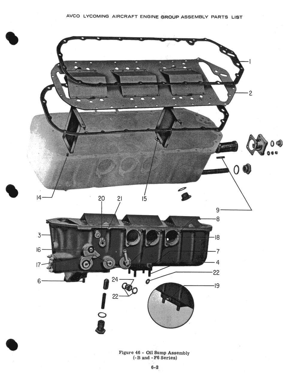
111 STD GASKET, Oil sump GASKET. Oil sump SPACER, Oil sump SUMP ASSEMBLY, Oil SUMP ASSEMBLY, Oil SUMP ASSEMBLY, Oil STUD, 5/16-18 x l-7/8 in long STUD, 5/16-18x 2-3/8 in. long STD STD STD STD STD STD STD STD STD STD STD e
112

113 SCREEN ASSEMBLY, Oil SUCTION PLUG, 5/8 ha hd, x Thd 1 STD-111 GASKET, 1.00 ID x 1-1/4 OD x 3/32 annular A,C GASKET, Oil screen cover COVER, Oil screen 1 2,C STD-8 WASHER, Plain, 1/4 in. 4 STD- 160 WASHER, Internal lock, 1/4 in. 4 STD-9 NUT, Plain, 1/ Figure Suction and Oil Pressure Screen Assemblies a 8-3
114 68192 GASKET, 011 scavange screen retainer 1 B SCREEN ASSEMBLY, Oil scavenge pump 3 STD-918 SCREW, Drilled head, 1/4-20 x 3/4 in. long 3 B 6-4

115 l STD-8 5 STD- 160 STD STD-28 STD STD STD STD STD STD STD BC 21 MS HOUSING, Breather 1 SPACER, Breather housing 2 WASHER, Plain, 1/4 in. WASHER, Internal lock, l/4 in. 2 NUT, Plain, 1/ GASKET, Breather cover 2 SCREEN, Breather housing COVER, Breather housing WASHING, Plain, #10 4 SCREW, Fill. hd., #10-24 x 3/4 in. long 4 RING, Oil seal, 1.00 ID x 1/8 section 1 PIPE, Breather 1 HOSE, 1.00 ID x 2-3/8 in. long 1 CLAMP, 1-3/8 ID x 9/16 in. wide 2 NIPPLE, 1/2 in. flared tube to 3/8 NPT. TUBE ASSEMBLY, Breather drain 1 HOSE, 1/2 in. ID x 2-1/4 in. long 1 CLAMP, Hose, 5/8 to 7/8 ID x 5/6 in. wide 2 PIPE, Breather conn. acc'y., housing SLEEVE, Shroud tube 1 GROMMET, 1/2 ID x 57/64 dia. groove, Fig. 35, Page Figure 49 - Breather System and Attaching Pub 6-5
116 AVCO LYCOMING AIRCRAFT ENGINE ASSEMBLY PARTS LIST B Figure 49A - Breather (Crosswise Accessory Housing) 6-5A

117 Figure 50 - Oil By-Pass Plunger Assembly 6-6
118
119 l PIPE, Intake, No. 1 and No. 6 cylinder PIPE, Intake, No. 1 and No. 6 cylinder PIPE, Intake, No. 2 and No. 5 cylinder PIPE, Intake. No. 2 and No. 5 cylinder PIPE. Intake. No. 3 and No. 4 cylinder PIPE; Intake; No. 3 and No. 4 cylinder GASKET, 2 bolt flange, 1-7/8 ld GASKET, 2 bolt flange, 1-3/4 ID FLANGE, Intake pipe, upper 6 STD-585 RING, 1/6 dia. section x 1-3/4 ID FLANGE, Intake pipe, lower HOSE. 1-3/4 ID x 2-3/16 OD x 1-3/4 in long 9 STD Figure 51 - Intake Pipes and Attaching Parts (-B and -F6 Series) 6-7
120 Figure 52 - Intake Pipes and Attaching Parts (-D1A) 6-7
 * - See Fig. 54 for B call-outs.")
121 1 A,B,C* their P/N CARBURETOR, Same as Bendix model, PS-5BD their P/N CARBURETOR, Same as Bendix model, PS-5BD their P/N STD-35 WASHER, Plain, 5/16 in. 4 STD-37 NOT, Plain, 5/ STD-36 LOCKNUT, 5/16 in. (Palnut) * - See Fig. 54 for B call-outs. 1 B* 1 c 4 4 l - Figure 53 - Carburetor Assembly (-B and -F6 Series) 6-8
O-540-A4B5 PARTS CATALOG WIDE CYLINDER FLANGE CRANKCASE MODEL ENGINES
 INTRODUCTION This illustrated parts catalog contains a complete parts listing for the Lycoming O-540-A4B5 wide cylinder flange crankcase model aircraft engines. Major assembly and sub-assembly parts of
O-540-F1B5 SERIES PARTS CATALOG WIDE CYLINDER FLANGE CRANKCASE MODEL ENGINES
 INTRODUCTION This illustrated parts catalog contains a complete parts listing for the Lycoming O-540-F1B5 series wide cylinder flange crankcase model aircraft engines. Major assembly and sub-assembly parts
Lycoming Aircraft Engines Parts Catalog
 Lycoming Aircraft Engines Parts Catalog 76 Series O-360, LO-360 Series Part No. PC-3 65 Oliver Street Williamsport, PA 770 Lycoming Aircraft Engines Parts Catalog 76 Series O-360, LO-360 Series Part No.
Lycoming AIRCRAFT ENGINES. IO-540-AC1A5 Wide Series Flange Crankcase Model Engine PARTS CATALOG PC
 AIRCRAFT ENGINES IO-540-ACA5 Wide Series Flange Crankcase Model Engine PARTS CATALOG PC-5- November 008 Lycoming 5 Oliver Street Williamsport, PA 770 U.S.A. 570/33-8 IO-540-ACA5 PARTS CATALOG This illustrated
TEXTRON Lycoming AIRCRAFT ENGINES
 TEXTRON Lycoming AIRCRAFT ENGINES O-60-AP Wide Cylinder Flange Crankcase Model Engines PARTS CATALOG PC-06-6 MARCH 99 0-60-AP PARTS CATALOG This illustrated parts catalog contains a complete parts listing
Lycoming Aircraft Engines Parts Catalog
 Aircraft Engines Parts Catalog IO-0-BG Wide Cylinder Flange Crankcase Model Engine Part No. PC-0- Oliver Street Williamsport, PA 770 Aircraft Engines Parts Catalog IO-0-BG Wide Cylinder Flange Crankcase
2003 Lycoming. All rights reserved. Lycoming and "Powered by Lycoming" are trademarks or registered trademarks of Lycoming.
 O-50-AD5 Engine Parts Catalog Lycoming Part Number: PC-55-3 003 Lycoming. All rights reserved. Lycoming and "Powered by Lycoming" are trademarks or registered trademarks of Lycoming. All brand and product
TEXTRON Lycoming AIRCRAFT ENGINES
 TEXTRON Lycoming AIRCRAFT ENGINES O-60-CF & -CP Wide Cylinder Flange Crankcase Model Engines PARTS CATALOG PC-06- OCTOBER 995 65 Oliver Street Williamsport, PA 770 U.S.A. 77/-6 Lycoming O-60-CF &-CP PARTS
SUPPLEMENT TO NO. 105
 SUPPLEMENT TO Model 0-30 Series Aircraft Engines Parts Catalog NO. 05 This supplement is provided to inform users of Lycoming parts catalogs of changes, deletions, additions and supersedures that have
Lycoming Aircraft Engines Parts Catalog
 Lycoming Aircraft Engines Parts Catalog TIO-360-CA6D Wide Cylinder Flange Models Part No. PC-06-3 65 Oliver Street Williamsport, PA 770 Lycoming Aircraft Engines Parts Catalog TIO-360-CA6D Wide Cylinder
PARTS CATALDG AIRCRAFT ENGINES
 PARTS CATALDG PC B115-1 AVCC L VCCMING IC-154D-C4D15D MCDEL Wide Cylinder Flange Model AIRCRAFT ENGINES..JULY 19S2 L1L7AVCa LYCOMING WILLIAMSPORT DIVISION 852 Oliver Street. Williamsport. Pennsylvania
LYCOMING MODEL SERIES AIRCRAFT ENGINES TABLE OF CONTENTS INTRODUCTION iii. INSTRUCTIONS FOR ORDERING PARTS.. ILLUSTRATED PARTS SECTION..
 TEXTRON Lycoming AIRCRAFT ENGINES O-30 Model Aircraft Engine PARTS CATALOG LYCOMING MODEL 0-30 SERIES AIRCRAFT ENGINES TABLE OF CONTENTS INTRODUCTION....................... iii. INSTRUCTIONS FOR ORDERING
Lycoming Aircraft Engines Parts Catalog
 Lycoming Aircraft Engines Parts Catalog AEIO-50-D Series -DA5, -DB5 Wide Cylinder Flange Crankcase Model Engines Part No. PC-5-5 Oliver Street Williamsport, PA 770 Textron Lycoming 5 Oliver Street Williamsport,
IO-540-K1H5 Series Illustrated Parts Catalog
 IO-50-KH5 Series Illustrated Parts Catalog November 983 Engine model IO-50-KK5, previously covered in this parts catalog, has been superseded by PC-5-KK5. PC-5-03 5 Oliver Street Williamsport, PA 770 IO-50-KH5
PUBLICATION REVISION
 Lycomlng 65 Oliver Street Williamsport, PA 770 U.S.A. 77/-6 TECHNICAL PUBLICATION REVISION REVISIOI No. PUBLICATION PUBLICATION No. PUBLICATION DATE IO-60-LA PC-06-A Engines PC-06- MAY, 996 This page(s)
TECHNICAL PUBLICATION SUPPLEMENT
 TEXTRON Lycoming TECHNICAL PUBLICATION SUPPLEMENT SUPPLEMENT No. ENGINE MODEL PUBLICATION No. PUBLICATION DATE PC-0--B O-90-D Series PC-0- January 9 This supplement is arranged in the same basic format
LYCOMING A Textron Company
 LYCOMING AEIO-360-HB PARTS CATALOG This illustrated parts catalog contains a complete parts listing for the Lycoming AEIO-360-HB wide cylinder flange crankcase model aircraft engines. Major assembly and
O 540 A4E5 Series Illustrated Parts Catalog
 O 540 A4E5 Series Illustrated Parts Catalog April 2012 PC 515 A4E5 2012 652 Oliver Street Williamsport, PA 17701 Lycoming Part Number: PC 515 A4E5 2012 by Avco Corporation. All Rights Reserved. Lycoming
Lycoming Aircraft Engines Parts Catalog
 Aircraft Engines Parts Catalog TIO-540 Series Standard Cylinder Flange Crankcase Models Part No. PC-35-6 652 Oliver Street Williamsport, PA 770 Reciprocating Engine Division/ Subsidiary of Textron Inc.
IO 360 M1B Series Illustrated Parts Catalog
 IO 360 M1B Series Illustrated Parts Catalog January 2011 PC 306 16 2011 652 Oliver Street Williamsport, PA 17701 Lycoming Part Number: PC 306 16 2011 by Avco Corporation. All Rights Reserved. Lycoming
O-320-E2G Series Illustrated Parts Catalog
 O-320-E2G Series Illustrated Parts Catalog December 2011 PC-203-7 2011 652 Oliver Street Williamsport, PA 17701 O-320-E2G Illustrated Parts Catalog Lycoming Part Number: PC-203-7 2011 by Avco Corporation.
O-360-A4N Series Illustrated Parts Catalog
 O-360-A4N Series Illustrated Parts Catalog May 2011 PC-306-3 2011 652 Oliver Street Williamsport, PA 17701 Lycoming Part Number: PC-306-3 2011 by Avco Corporation. All Rights Reserved. Lycoming and Powered
O-320-A2C, -A2D Series Illustrated Parts Catalog
 O-320-A2C, -A2D Series Illustrated Parts Catalog September 2011 PC-203-2 2011 652 Oliver Street Williamsport, PA 17701 O-320-A2C, -A2D Illustrated Parts Catalog Lycoming Part Number: PC-203-2 2011 by Avco
O-320-D3G Series Illustrated Parts Catalog
 O-320-D3G Series Illustrated Parts Catalog AUGUST 2012 PC-203-D3G 2012 652 Oliver Street Williamsport, PA 17701 O-320-D3G Series Illustrated Parts Catalog AUGUST 2012 PC-203-D3G 2012 652 Oliver Street
O-360-C1G Series Illustrated Parts Catalog
 O-360-C1G Series Illustrated Parts Catalog April 2011 PC-306-4 2011 652 Oliver Street Williamsport, PA 17701 Lycoming Part Number: PC-306-4 2011 by Avco Corporation. All Rights Reserved. Lycoming and Powered
IO-540-AE1A5 Series Illustrated Parts Catalog
 IO-540-AE1A5 Series Illustrated Parts Catalog PC-615-AE1A5 (Replaces PC-615-13) 2013 652 Oliver Street Williamsport, PA 17701 IO-540-AE1A5 Series Illustrated Parts Catalog PC-615-AE1A5 (Replaces PC-615-13)
Lycoming Aircraft Engines Parts Catalog
 Aircraft Engines Parts Catalog TIO/LTIO-540-UA Series Wide Cylinder Flange Model Part No. PC-35-65 Oliver Street Williamsport, PA 770 Aircraft Engines Parts Catalog TIO/LTIO-540-UA Series Wide Cylinder
********NOTICE********
 IO-540-K1A5 Series Illustrated Parts Catalog February 2015 ********NOTICE******** This parts catalog, PC-615-K1A5 Series (models IO-540-K1A5, IO-540-K1A5D) supersedes the previous IO-540-K1A5, IO-540-K1A5D
LYCOMING PARTS CATALO G
 LYCOMING PARTS CATALO G I O-70 AIRCRAFT SERIES ENGINES LYCOMING WILLIAMSPORT DIVISION WILLIAMSPORT, PENNSYLVANIA 770 PC-9 November 977 SUPPLEMENTAL PARTS LIST SSP77 To Provide Parts Coverage for Avco Lycoming
Lycoming Aircraft Engines Parts Catalog
 Aircraft Engines Parts Catalog TIO/LTIO-540-V2AD Wide Cylinder Flange Model Part No. PC-35-2 652 Oliver Street Williamsport, PA 770 Aircraft Engines Parts Catalog TIO/LTIO-540-V2AD Wide Cylinder Flange
O-320-A2B, -A3B Series Illustrated Parts Catalog
 O-320-A2B, -A3B Series Illustrated Parts Catalog August 2011 PC-203-1 2011 652 Oliver Street Williamsport, PA 17701 O-320-A2B, -A3B Illustrated Parts Catalog Lycoming Part Number: PC-203-1 2011 by Avco
TECHNICAL PUBLICATION REVISION
 Reciprocating Engine Division/ Subsidiary of Textron Inc. 65 Oliver Street Williamsport, PA 770 U.S.A. 77/33-68 TECHNICAL PUBLICATION REVISION REVISION No. PUBLICATION PUBLICATION No. PUBLICATION DATE
O-320-E2D, -E3D Series Illustrated Parts Catalog
 O-320-E2D, -E3D Series Illustrated Parts Catalog October 2011 PC-203-6 2011 652 Oliver Street Williamsport, PA 17701 O-320-E2D, -E3D Series Illustrated Parts Catalog October 2011 PC-203-6 2011 652 Oliver
TIO-540-AJ1A Illustrated Parts Catalog
 TIO-540-AJ1A Illustrated Parts Catalog May 2016 PC-TIO-540-AJ1A (Supersedes PC-315-12) 2016 652 Oliver Street Williamsport, PA 17701 Lycoming Part Number: PC-TIO-540-AJ1A (Supersedes PC-315-12) For additional
YO-233-B2A Illustrated Parts Catalog
 YO-233-B2A Illustrated Parts Catalog March 2016 PC-YO-233-B2A Supersedes PC-901-1 2016 652 Oliver Street Williamsport, PA 17701 Lycoming Part Number: PC-YO-233-B2A Supersedes PC-901-1 2016 by Avco Corporation.
O-320-H 76 Series Illustrated Parts Catalog
 O-320-H 76 Series Illustrated Parts Catalog PC-122-H 76 Series 2013 652 Oliver Street Williamsport, PA 17701 O-320-H 76 Series Illustrated Parts Catalog PC-122-H 76 Series 2013 652 Oliver Street Williamsport,
TIO-540-AE2A Illustrated Parts Catalog
 TIO-540-AE2A Illustrated Parts Catalog December 2013 PC-315-7 Second Edition 2013 652 Oliver Street Williamsport, PA 17701 TIO-540-AE2A Illustrated Parts Catalog Lycoming Part Number: PC-315-7 2013 Lycoming.
LIO-360-B1G6 Illustrated Parts Catalog
 LIO-360-B1G6 Illustrated Parts Catalog July 2017 PC-LIO-360-B1G6 2017 Lycoming Part Number: PC-LIO-360-B1G6 For additional information: Mailing address: Lycoming Engines 652 Oliver Street Williamsport,
O-360-A4M Series Illustrated Parts Catalog
 O-360-A4M Series Illustrated Parts Catalog PC-306-A4M 2012 652 Oliver Street Williamsport, PA 17701 O-360-A4M Series Illustrated Parts Catalog PC-306-A4M 2012 652 Oliver Street Williamsport, PA 17701 O-360-A4M
O-320-E1A, -E2A Series Illustrated Parts Catalog
 O-320-E1A, -E2A Series Illustrated Parts Catalog November 2011 PC-203-3 2011 652 Oliver Street Williamsport, PA 17701 O-320-E1A, -E2A Illustrated Parts Catalog Lycoming Part Number: PC-203-3 2011 by Avco
Lycoming Aircraft Engines Parts Catalog
 Lycoming Aircraft Engines Parts Catalog HO-360-CA Wide Cylinder Flange Crankcase Model Engines Part No. PC-306-0 65 Oliver Street Williamsport, PA 770 Lycoming Aircraft Engines Parts Catalog HO-360-CA
Lycoming Aircraft Engines Parts Catalog
 Lycoming ircraft Engines Parts Catalog GSO-80 and IGSO-80 Series ircraft Engines Part No. PC- Oliver Street Williamsport, P 770 Lycoming ircraft Engines Parts Catalog GSO-80 and IGSO-80 Series ircraft
Textron Company. A Textron Company. Engine Parts Catalog AEIO-360-BB -B1F & LYCYMNG Oliver Street Williamsport, PA Part No.
 Textron Company Engine Parts Catalog AEIO-60-BB -BF & -BH LYCYMNG 005 Decembber Part No. PC-06-005 65 Oliver Street Williamsport, PA 770 Textron Company Engine Parts Catalog AEIO-60-BB -BF & -BH LYCYMNG
(L)IO-360-M1A Illustrated Parts Catalog
IO-360-M1A Illustrated Parts Catalog") (L)IO--M1A Illustrated Parts Catalog February 2016 PC-(L)IO--M1A (Supersedes PC-306-14) 2016 652 Oliver Street Williamsport, PA 17701 Lycoming Part Number: PC-(L)IO--M1A (Supersedes PC-306-14) 2016 by
(L)IO--M1A Illustrated Parts Catalog February 2016 PC-(L)IO--M1A (Supersedes PC-306-14) 2016 652 Oliver Street Williamsport, PA 17701 Lycoming Part Number: PC-(L)IO--M1A (Supersedes PC-306-14) 2016 by
TECHNICAL PUBLICATION REVISION
 Lycoming Textron Lycoming/Subsidiary of Textron Inc. 65 Oliver Street Williamsport, PA 770 U.S.A. 77/33-68 REVISION No. PC06--A TECHNICAL PUBLICATION REVISION ENGINE MODEL 0/LIO-360-C, -J, HIO, TIO, AEIO-360
Lycoming Aircraft Engines Parts Catalog
 Lycoming Aircraft Engines Parts Catalog O-30, IO-30 and LIO-30 Series Part No. PC-03 65 Oliver Street Williamsport, PA 770 Lycoming Aircraft Engines Parts Catalog O-30, IO-30 and LIO-30 Series Part No.
TECHNICAL PUBLICATION SUPPLEMENT
 AVCO LYCOMING WILLIAMSPORT DIVISION 65 Oliver Street, Wlllamsport, Pennsylvania 770' AVCO LYCOMING ENGINE GROUP TECHNICAL PUBLICATION SUPPLEMENT SUPPLEEMENT No. ENGINE MODEL PUBLICATION No. PUBLICATION
GENSET ENGINE-G25/30. ITEM PART NO. DESCRIPTION QTY QTY REMARKS No. G25 G30
 ITEM PART NO. DESCRIPTION QTY QTY REMARKS No. G25 G30 1 CONTENTS SHEET DESCRIPTION PAGE NO. NO. E-1 CYLINDER BLOCK, LINER AND OIL SUMP 2 E-2 CYLINDER HEAD 6 E-3 PISTON AND CONNECTING ROD ASSY 10 E-4 CRANK
 REQUIRES SPECIAL TOOLS TO INSTALL. SEE REPAIR INSTRUCTION MANUAL. 411 718 38 3 1027 1 127 127 127A 1080 1081 1028 127 718A 127 718 44B 718A 2 44A 493 44 1069 112 718B 1019 LABEL KIT 1058 OWNER S MANUAL
IO-390-C Series Engine Illustrated Parts Catalog
 IO-390- Series Engine Illustrated Parts atalog February 1, 2017 P-IO-390-2017 52 Oliver Street Williamsport, PA 17701 Lycoming Part Number: P-IO-390- For additional information: Mailing address: Lycoming
Illustrated Parts List to
 FORM MS-5838-9/94 REPLACES FORM MS-5838-10/93 FILE IN SECT. 2 OF SERVICE MANUAL 122700 to 122799 Illustrated Parts List Model Series 122700 to 122799 TYPE NUMBERS 0101 through 0108, 0115 through 0213,
mi Model 108 Compact Tractor Parts Catalog
 mi Model 108 Compact Tractor Parts Catalog Catalog No. 1226 PRICE 75 CENTS CASE MODEL 108 COMPACT TRACTOR Parts Catalog No. 1226 Leitch 2500 9-72 "'^^^l" 1" ifif --C: ^1=5 t^dj d- CASE MODEL 108 COMPACT
Illustrated Parts List Vanguard to Compliance
 Non-Compliance Illustrated Parts List Vanguard Model Series 104700 to 104799 FORM MS-9878 7/93 REPLACES FORM MS-9878 5/92 FILE IN SECT. 2 OF SERVICE MANUAL 104700 to 104799 Compliance TYPE NUMBERS 0101,
Introduction WISCONSIN ROBIN WR-WOI-21 OPM REV DATE: This catalog is designed to identify Wisconsin Robin parts.
 WISCONSIN ROBIN WR-WOI- OPM REV DATE: 0- Introduction This catalog is designed to identify Wisconsin Robin parts. When ordering parts, it is always advisable to list the engine model, specification number
IO-390-A Series Engine Illustrated Parts Catalog
 IO-90- Series Engine Illustrated Parts Catalog July 20 PC-IO-90- (Supersedes PC-409-) 20 52 Oliver Street Williamsport, P 770 IO-90- Series Engine Illustrated Parts Catalog Lycoming Part Number: PC-IO-90-
AIRCRAFT ENGINE ILLUSTRATED PARTS CATALOG
 C-75, C-85, C-90 & O-00-A, B & C AIRCRAFT ENGINE ILLUSTRATED PARTS CATALOG This illustrated parts catalog is provided as a reference for non-production Continental Motors aircraft engines. Part numbers
Lycoming Aircraft Engines Parts Catalog
 Lycoming Aircraft Engines Parts Catalog TIO-541 Series Part No. PC-120 652 Oliver Street Williamsport, PA 17701 Lycoming Aircraft Engines Parts Catalog TIO-541 Series Part No. PC-120 652 Oliver Street
Illustrated Parts List to
 TYPE NUMBERS 0022 through 0035, 0040 through 0062, 0070, 0076,0100, 0102, 0120 through 0125, 0307, 0318,0320, 0326, 0340 through 0366, 0370 through 0378, 0382, 0385, 0390, 0391, 0394, 0398, 0402, Illustrated
Illustrated Parts List to
 TYPE NUMBERS 0101, 0102, 0106, 0108, 0109, 0115 through 0224, 0415, 0418, 0467, 0468, 0601 through 0683, 3101 through 3108, 3110 through 3163, 3167 through 3181. Illustrated Parts List Model Series 124700
9/7/2014 F9.9MSHV 1997 / CYLINDER CRANKCASE Yamaha Motor Corporation, U.S.A. All rights reserved.
 F9.9MSHV 997 Page of 45 9/7/04 F9.9MSHV 997 / CYLINDER CRANKCASE 04 Yamaha Motor Corporation, U.S.A. All rights reserved. F9.9MSHV 997 Page of 45 9/7/04 Part List F9.9MSHV 997 / CYLINDER CRANKCASE REF
Illustrated Parts List Industrial/Commercial to
 FORM MS-9479 6/95 REPLACES FORM MS-9479 10/94 FILE IN SECT. 2 OF SERVICE MANUAL 402700 to 402799 Illustrated Parts List Industrial/Commercial Model Series 402700 to 402799 TYPE NUMBERS 1115 through 1117,
REMOVAL AND INSTALLATION LABOR ALLOWANCE GUIDEBOOK FOR RECIPROCATING AIRCRAFT ENGINES
 REMOVAL AND INSTALLATION LABOR ALLOWANCE GUIDEBOOK FOR RECIPROCATING AIRCRAFT ENGINES SSP-875 Revision May 2000 2000 by Textron Lycoming All Rights Reserved -INTRODUCTION- The labor hours shown in this
Craftsman Snow Thrower Model PARTS LIST
 Craftsman Snow Thrower Model 24.88955 11 13 3 26 24 9 1 18 54 6 25 15 20 23 16 5 14 1 55 9 4 4 28 8 30 2 5 56 35 36 46 3 39 50 53 43 38 48 52 42 51 41 40 49 4 44 31 45 31 21 29 34 9 19 10 32 22 26 Craftsman
Illustrated Parts List
 Illustrated Parts List TA-J7-400026 (ETS-2040) August 202 Contents How To Use The Illustrated Parts List... AUXILIARY COUNTERSHAFT ASSEMBLY... 4 AUXILIARY DRIVE GEAR ASSEMBLY... 5 AUXILIARY MAINSHAFT ASSEMBLY...
365-SUB Engine : Engine Assembly 365-SUB [1/1] Page 1 of 5
![365-SUB Engine : Engine Assembly 365-SUB [1/1] Page 1 of 5](/thumbs/91/105185559.jpg "365-SUB Engine : Engine Assembly 365-SUB [1/1] Page 1 of 5") Page 1 of 5 1 951-11012 Bolt 2 951-11054 Valve Cover 2 951-11054 1 Valve Cover 3 731-07059 Breather Hose 4 726-04101 Hose Clamp 6 N/A 1 Intake Valve Spring Seat 7 751-11124 Pivot Locking Nut 7 751-11124
Page 1 of 5 1 951-11012 Bolt 2 951-11054 Valve Cover 2 951-11054 1 Valve Cover 3 731-07059 Breather Hose 4 726-04101 Hose Clamp 6 N/A 1 Intake Valve Spring Seat 7 751-11124 Pivot Locking Nut 7 751-11124
Service Parts. Doosan 11.1 L. Engine. Engine Model: Generator Models: 180/200REZX 180/200RZX TP /09
 Service Parts Engine Engine Model: Doosan. L Generator Models: 80/00REZX 80/00RZX TP-0 /09 Table of Contents Introduction... Numbering System Significance... Illustrations... How to Find Part Numbers...
DIAMO Discovery XLT PARTS CATALOG Engine First Edition August 2008
 DIAMO Discovery XLT PARTS CATALOG - 500 Engine First Edition August 2008 Copyright 2007-2008 LS MotorSports, LLC. Reproduction without written permission is completely forbidden. The information and diagrams
FORD - Cyl Block and Related Parts
 FORD - Cyl Block and Related Parts Ref Description Qty All 302 Qty 351 Qty 351-HP 1 BLOCK ASSEMBLY 1 59-4046 1 59-4047 1 59-4047 2 PLUG - 1½ CUP - BRASS 6 59-4048 6 59-4048 6 59-4048 3 PLUG - OIL PASSAGE
SHEET DESCRIPTION PAGE NO. NO.
 CONTENTS SHEET DESCRIPTION PAGE NO. NO. E-1 CYLINDER BLOCK, LINER AND OIL SUMP 2 E-2 CYLINDER HEAD 6 E-3 PISTON AND CONNECTING ROD ASSY 10 E-4 CRANK SHAFT 12 E-5 TIMING GEAR COVER & SEALING 14 E-6 TIMING
DVX 300 Euro. Model Number A2012KSF2BEUK SHARE OUR PASSION.
 ATV 2012ATV Illustrated Parts Manual DVX 300 Euro Model Number A2012KSF2BEUK TM SHARE OUR PASSION. TABLE OF CONTENTS 2012 ATV DVX 300 Euro (Model No. A2012KSF2BEUK) BODY PANEL AND HEADLIGHT ASSEMBLY...
Illustrated Parts Manual. Model Number A2011KSF2BEUZ (Black-Cat Green) A2011KSF2BEOJ (White-Cat Green)
 A2011KSF2BEOJ (White-Cat Green)") Illustrated Parts Manual 2 1 10 DVX 300 Euro Model Number A2011KSF2BEUZ (Black-Cat Green) A2011KSF2BEOJ (White-Cat Green) S H A R E O U R PAS S IO N. TM TABLE OF CONTENTS 2011 ATV DVX 300 Euro Black-Cat
Illustrated Parts Manual 2 1 10 DVX 300 Euro Model Number A2011KSF2BEUZ (Black-Cat Green) A2011KSF2BEOJ (White-Cat Green) S H A R E O U R PAS S IO N. TM TABLE OF CONTENTS 2011 ATV DVX 300 Euro Black-Cat
Illustrated Parts List
 Illustrated Parts List 3003340 September 2011 Contents How To Use The Illustrated Parts List...3 AIR FILTER REGULATOR...4 AUXILIARY COUNTERSHAFT ASSY....5 AUXILIARY DRIVE GEAR...6 AUXILIARY MAINSHAFT ASSY...7
PARTS MANUAL. RGD5000 Generator. Model. PUB-GP1204 Rev. 7/98
 PARTS MANUAL Model RGD5000 Generator PUB-GP1204 Rev. 7/98 GROUP INDEX Group Name Page GENERATOR GROUP... 4 FRAME and FUEL TANK GROUP... 6 CONTROL BOX GROUP... 8 CRANKCASE GROUP... 12 CYLINDER and CYLINDER
Illustrated Parts List to
 FORM MS-2442-9/93 REPLACES FORM MS-2442-11/92 FILE IN SECT. 2 OF SERVICE MANUAL Illustrated Parts List Industrial/Commercial Model Series TYPE NUMBERS 0101 through 0104, 0116 through 0120, 0122 through
Service Parts. John Deere 3029DF 3029TF 3029TF270. Engine. Engine Models: Generator Models: 20ROZJB REOZJB 20DSJB DSEJB.
 Service Parts Engine Engine Models: John Deere 3029DF 3029TF 3029TF270 Generator Models: 20ROZJB 20--40REOZJB 20DSJB 20--40DSEJB TP- 12/03b Table of Contents Description Page Description Page Introduction...
ATV 50 DVX BLACK-RED (A2008KSA2BUSD) Page 1 of 60 AIR INTAKE ASSEMBLY
 Page 1 of 60 AIR INTAKE ASSEMBLY") 2008 ATV 50 DVX BLACK-RED (A2008KSA2BUSD) Page 1 of 60 AIR INTAKE ASSEMBLY 2008 ATV 50 DVX BLACK-RED (A2008KSA2BUSD) Page 2 of 60 AIR INTAKE ASSEMBLY Ref # Part Number Qty S/P/F Description 1 3303-005
2008 ATV 50 DVX BLACK-RED (A2008KSA2BUSD) Page 1 of 60 AIR INTAKE ASSEMBLY 2008 ATV 50 DVX BLACK-RED (A2008KSA2BUSD) Page 2 of 60 AIR INTAKE ASSEMBLY Ref # Part Number Qty S/P/F Description 1 3303-005
ATV 300 DVX CAT GREEN (A2011KSF2BUSZ) Page 1 of 56 AIR INTAKE ASSEMBLY
 Page 1 of 56 AIR INTAKE ASSEMBLY") 2011 ATV 300 DVX CAT GREEN (A2011KSF2BUSZ) Page 1 of 56 AIR INTAKE ASSEMBLY 2011 ATV 300 DVX CAT GREEN (A2011KSF2BUSZ) Page 2 of 56 AIR INTAKE ASSEMBLY Ref # Part Number Qty S/P/F Description 1 3303-705
2011 ATV 300 DVX CAT GREEN (A2011KSF2BUSZ) Page 1 of 56 AIR INTAKE ASSEMBLY 2011 ATV 300 DVX CAT GREEN (A2011KSF2BUSZ) Page 2 of 56 AIR INTAKE ASSEMBLY Ref # Part Number Qty S/P/F Description 1 3303-705
Illustrated Parts List to
 Illustrated Parts List Model Series 124800 to 124899 FORM MS-2436-9/94 REPLACES FORM MS-2436-10/93 FILE IN SECT. 2 OF SERVICE MANUAL 124800 to 124899 TYPE NUMBERS 0106, 0206 through 0284, 0406 through
9/7/2014 T9.9ELRZ 2001 / TOP COWLING Yamaha Motor Corporation, U.S.A. All rights reserved.
 T9.9ELRZ 00 Page of 56 9/7/0 T9.9ELRZ 00 / TOP COWLING 0 Yamaha Motor Corporation, U.S.A. All rights reserved. T9.9ELRZ 00 Page of 56 9/7/0 Part List T9.9ELRZ 00 / TOP COWLING REF - NO PART NUMBER PART
MODEL QP-402H CENTRIFUGAL PUMP
 OPERATION AND PARTS MANUAL MODEL QP-402H CENTRIFUGAL PUMP (Honda GX240K1PMT2/GX240U1PMT2 Gasoline Engine) Revision #0 (10/24/07) To find the latest revision of this publication, visit our website at: www.multiquip.com
ATV 90 UTILITY GREEN (A2006KUB2BUSG) Page 1 of 60 AIR INTAKE ASSEMBLY
 Page 1 of 60 AIR INTAKE ASSEMBLY") 2006 ATV 90 UTILITY GREEN (A2006KUB2BUSG) Page 1 of 60 AIR INTAKE ASSEMBLY 2006 ATV 90 UTILITY GREEN (A2006KUB2BUSG) Page 2 of 60 AIR INTAKE ASSEMBLY Ref # Part Number Qty S/P/F Description 1 3303-005
2006 ATV 90 UTILITY GREEN (A2006KUB2BUSG) Page 1 of 60 AIR INTAKE ASSEMBLY 2006 ATV 90 UTILITY GREEN (A2006KUB2BUSG) Page 2 of 60 AIR INTAKE ASSEMBLY Ref # Part Number Qty S/P/F Description 1 3303-005
Mfg. No:
 Parts Manual Mfg. No: 220707-0142-99 Copyright 2017 Briggs and Stratton. All Rights reserved 22-Jun-2017 Model Components Table Of Contents Page Blower Hsg, Sump, Oil Fill.............................................................................
For Discount Tecumseh Engine Parts Call or HH E Page 1 of 8 Engine Parts List #1
 HH60-105080E Page 1 of 8 Engine Parts List #1 HH60-105080E Page 2 of 8 Engine Parts List #1 1 34761 0 Cylinder Assy. (Cast iron liner) (2-5/8" 2 27652 0 Pin, Dowel 3 27642 0 Plug, Drain 4 27876B 0 Seal,
TIME OF COMPLIANCE: At owner s discretion or when part replacement is necessary.
 52 Oliver Street Williamsport, PA. 770 U.S.A. Telephone + (877) 839-7878 (U.S. and Canada) Telephone + (570) 327-7222 (International) Fax + (570) 327-70 Email Technicalsupport@lycoming.com www.lycoming.com
ATV 90 UTILITY CALIFORNIA GREEN (A2008KUB2BCAG) Page 1 of 58 AIR INTAKE ASSEMBLY
 Page 1 of 58 AIR INTAKE ASSEMBLY") 2008 ATV 90 UTILITY CALIFORNIA GREEN (A2008KUB2BCAG) Page 1 of 58 AIR INTAKE ASSEMBLY 2008 ATV 90 UTILITY CALIFORNIA GREEN (A2008KUB2BCAG) Page 2 of 58 AIR INTAKE ASSEMBLY Ref # Part Number Qty S/P/F Description
2008 ATV 90 UTILITY CALIFORNIA GREEN (A2008KUB2BCAG) Page 1 of 58 AIR INTAKE ASSEMBLY 2008 ATV 90 UTILITY CALIFORNIA GREEN (A2008KUB2BCAG) Page 2 of 58 AIR INTAKE ASSEMBLY Ref # Part Number Qty S/P/F Description
Illustrated Parts List to
 Illustrated Parts List Vanguard Model Series 161400 to 161499 TYPE NUMBERS 0010 through 0036, 0040, 0041, 0047, 0049, 0051, 0070, 0073, 0079 through 0085, 0090, 0101, 0110 through 0135, 0199. FORM MS 9877
PARTS MANUAL SUPPORTED BY HUSTLER TURF EQUIPMENT AND EXCEL INDUSTRIES, INC.
 SHIBAURA DIESEL ENGINE MODEL: N843 and N843L PARTS MANUAL SUPPORTED BY HUSTLER TURF EQUIPMENT AND EXCEL INDUSTRIES, INC. Table of Contents Chapter 1 General Information....................................
Carrier Transicold Diesel Engine CT4-91-TV (V1505) Service Parts List Rev A
 Service Parts List Rev A") Carrier Transicold Diesel Engine CT--TV (V0) Service Parts List -0 Rev A Service Parts List DIESEL ENGINE CT--TV (V0) CONTENTS INTRODUCTION... REPLACEMENT ENGINE PART NO.... ORDERING INSTRUCTIONS... GENERAL
Carrier Transicold Diesel Engine CT--TV (V0) Service Parts List -0 Rev A Service Parts List DIESEL ENGINE CT--TV (V0) CONTENTS INTRODUCTION... REPLACEMENT ENGINE PART NO.... ORDERING INSTRUCTIONS... GENERAL
MULTIQUIP MODEL QP-303H CENTRIFUGAL PUMP (HONDA GX160 GASOLINE ENGINE)
") OPERATION AND PARTS MANUAL MULTIQUIP MODEL QP-303H CENTRIFUGAL PUMP (HONDA GX160 GASOLINE ENGINE) Revision #0 (01/30/06) To find the latest revision of this publication, visit our website at: www.multiquip.com
OPERATION AND PARTS MANUAL MULTIQUIP MODEL QP-303H CENTRIFUGAL PUMP (HONDA GX160 GASOLINE ENGINE) Revision #0 (01/30/06) To find the latest revision of this publication, visit our website at: www.multiquip.com
Illustrated Parts List to
 Illustrated Parts List Model Series TYPE NUMBERS 0111 through 0199, 0200 through 0213, 0300 through 0353, 1345,1353, 2035 through 2073, 2135 through 2174, 4001 through 4090, 5001, 5005, 5006, 5035 through
Caution: This document contains mixed page sizes (8.5 x 11 or 11 x 17), which may affect printing. Please adjust your printer settings according to
, which may affect printing. Please adjust your printer settings according to") Caution: This document contains mixed page sizes (8.5 x 11 or 11 x 17), which may affect printing. Please adjust your printer settings according to the size of each page you wish to print. Parts Catalog
Caution: This document contains mixed page sizes (8.5 x 11 or 11 x 17), which may affect printing. Please adjust your printer settings according to the size of each page you wish to print. Parts Catalog
DVX 90 MODEL NUMBER A2008KSB2BUSD (BLACK-RED) MODEL NUMBER A2008KSB2BUSE (BLACK-CAT GREEN) MORE TO GO ON. TM
 MODEL NUMBER A2008KSB2BUSE (BLACK-CAT GREEN) MORE TO GO ON. TM") 2008 DVX 90 Illustrated Parts Manual MODEL NUMBER A2008KSB2BUSD (BLACK-RED) MODEL NUMBER A2008KSB2BUSE (BLACK-CAT GREEN) MORE TO GO ON. TM TABLE OF CONTENTS Black-Red (Model No. A2008KSB2BUSD) Black-Cat
2008 DVX 90 Illustrated Parts Manual MODEL NUMBER A2008KSB2BUSD (BLACK-RED) MODEL NUMBER A2008KSB2BUSE (BLACK-CAT GREEN) MORE TO GO ON. TM TABLE OF CONTENTS Black-Red (Model No. A2008KSB2BUSD) Black-Cat
Air Intake/Filtration
 Air Intake/Filtration Air Intake/Filtration Ref # Part Description Qty 25 048 -S CLEANER, AIR-CANISTER (includes 2-8) 2 25 096 06-S COVER ASSMBLY,AIR CLEANER (includes 3,4) 3 24 462 07-S VALVE, DUST EJECTOR
9/8/ MSHZ 2001 / TOP COWLING Yamaha Motor Corporation, U.S.A. All rights reserved.
 9.9MSHZ 00 Page of 47 9/8/04 9.9MSHZ 00 / TOP COWLING 04 Yamaha Motor Corporation, U.S.A. All rights reserved. 9.9MSHZ 00 Page of 47 9/8/04 Part List 9.9MSHZ 00 / TOP COWLING REF - NO PART NUMBER PART
LB361B PARTS LIST COMPRESSORS CB-5E /06. Bulletins Needed For Complete Parts List. Gasket Set, Repair Kits and Special Tools
 COMPRESSORS CB-5E-031 2011/06 LB361B PARTS LIST Serial # ID# Gasket Set, Repair Kits and Special Tools Gasket Set Buna-N & Aluminum 793099 Top End Repair Kit 793229 Includes Piston Rings & Expanders, Packing
Page 1 of HP B&S Vanguard Engine
 1405 Page 1 of 41 14 HP B&S Vanguard Engine 1405 Page 2 of 41 14 HP B&S Vanguard Engine Ref # Part Number Qty S/P/F Description BS-28Q777-0647-E1 1 14 HP B&S Vanguard Engine 1 BS-496412 1 Cylinder Assembly
UNIVERSAL ATOMIC DIESEL MODEL (16 H.P.) PARTS MANUAL. Universal Motors
 PARTS MANUAL. Universal Motors") UNIVERSAL ATOMIC DIESEL MODEL 20 5416 (16 H.P.) PARTS MANUAL Universal Motors This copy of the Universal Motors Owners Manual has been re-created using images computer scanned from a manual rather than
UNIVERSAL ATOMIC DIESEL MODEL 20 5416 (16 H.P.) PARTS MANUAL Universal Motors This copy of the Universal Motors Owners Manual has been re-created using images computer scanned from a manual rather than
GN-FYS-76-SC SCREW WHEEL GN-FYS-76-9
 GN-FYS-76-1 RUBBER FOOT GN-FYS-76-2 LEG GN-FYS-76-3 FLAT WASHER GN-FYS-76-4 HEX NUT GN-FYS-76-5 LOCK WASHER GN-FYS-76-6 HEX BOLT GN-FYS-76-7 DISCHARGE CHUTE GN-FYS-76-8 MOVABLE DOOR GN-FYS-76-9 TUBE GN-FYS-76-10
Illustrated Parts Manual
 1 10 Illustrated Parts Manual 2 425 CR EFT Model Number A2011IRK4CETR (Red) S H A R E O U R PA S S IO N. TM TABLE OF CONTENTS 2011 ATV 425 CR EFT Red (A2011IRK4CETR) FRONT RACK, BODY PANEL, AND HEADLIGHT
Use your Service Parts List to ensure proper part number and nomenclature identification. Table of Contents
 WISCONSIN ROBIN WR-WI-5VII 85VPM REV DATE: 0-9 Specification No s. 8006, 8007 Introduction This catalog is designed to identify Wisconsin Robin parts. When ordering parts, it is always advisable to list