Wind Direction Vane. Z345. Installation Guide.
|
|
|
- Caren Booker
- 5 years ago
- Views:
Transcription


1 Wind Direction Vane. Z345 Installation Guide.
2 Wind Direction Vane Installation Guide Index. Description. 3 Features. 3 Ordering Information. 3 Specifications. 3 Product Liability. 3 Connection & Wiring. 4 Wiring. 4 Wind Vane Dimensions. 4 Mounting Plate Dimensions. 4 Theory or Operation. 5 Site Selection. 5 Mounting. 5 Orientation. 5 Wind Vane Assembly Diagram. 6 Maintenance. 6 Alignment Calibration. 7 2
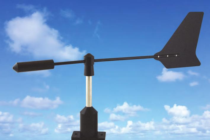
3 Wind Direction Vane. Description. The Wind Vane is a highly responsive current loop output wind vane. The vane body is made from stainless steel and anodised aluminium. Stainless steel shafts, bearings and fittings are used throughout. A precision potentiometer is coupled to the vane shaft to provide an analogue output proportional to the wind direction. A counterweight provides precision balancing of the tail assembly on the shaft. Features. Rugged Construction. Temperatures of -5 to 60 C. Various Output Types. High Accuracy. Easy Installation. 4~20mA. Voltage. Potentiometer. Z345 Ordering Information. WD-CL: WD-V: WD-P: Wind Vane with 4~20mA output. Wind Vane with 0~5Vdc output. Wind Vane with Potentiometer output. Specifications. Common Specifications: Sensor Type Rotating vane. Range 10 ~350 (±10 dead band at North). Accuracy ±3% max (10 ~350 ). Linearity Error ±2% max (10 ~350 ). Cable 5m, UV Resistant. Rotation Life 10,000,000 cycles. Operating Temperature -5 ~60 C. Temperature Error ±350ppm/ C typical. EMC Compliances Emissions EN A. Immunity EN Safety Compliances EN Dimensions - Overall L=410, H=230mm. - Mounting Plate L=70mm, W=38mm, H=6.5mm, PCD=55mm. Current Output Specifications: Output 4~20mA, 2 wire (Loop Powered). Damping 2min Nominal over 90. Load Resistance 24Vdc. Supply Voltage 12~24Vdc. Range 4mA = 0 (north), 8mA = 90 (east), 12mA = 180 (south), 16mA = 270 (west). Voltage Output Specifications: Output 0~5Vdc, 3 Wire (common ground). Damping 2min Nominal over 90. Power Supply Required 12Vdc. Potentiometer Output Specifications: Transducer Wiper Output Potentiometer 10,000Ω. 1MΩ in series. Product Liability. This information describes our products. It does not constitute guaranteed properties and is not intended to affirm the suitability of a product for a particular application. Due to on-going research and development, designs, specifications, and documentation are subject to change without notification. Regrettably, omissions and exceptions cannot be completely ruled out. No liability will be accepted for errors, omissions or amendments to this specification. Technical data are always specified by their average values and are based on Standard Calibration Units at 25C, unless otherwise specified. Each product is subject to the Conditions of Sale. Warning: These products are not designed for use in, and should not be used for patient connected applications. In any critical installation an independent fail-safe back-up system must always be implemented. 3
4 Connections & Wiring. All wind vane s come fitted with a 5 metre UV resistant cable. WD-CL 4~20mA Output (Loop Powered). Red Vdc Power Supply. Black Field Station / Indicator etc. WD-V Voltage Output. Yellow + (12Vdc) Vdc Power Supply. Blue + (0~5Vdc) Green - (COM) + - Field Station / Indicator etc. WD-P Potentiometer Output. Yellow 10KΩ Potentiometer Blue - Wiper Output (includes 1MΩ in series). Green Wiring. All cables should be good quality overall screened INSTRUMENTATION CABLE with the screen earthed at one end only. Signal cables should be laid a minimum distance of 300mm from any power cables. It is recommended that you use power supplies with ungrounded outputs and that you do not ground current loops. Lightning arrestors should be used when there is a danger from this source. 4
5 Wind Vane Dimensions. Mounting Plate Dimensions. 55mm 38mm 6.5mm 70mm Theory of Operation. Wind direction is defined as the direction of the source of the wind flow measured in degrees from true north in a clockwise increasing angle. A potentiometer is mounted directly to the Vane shaft and rotates with the shaft. Changes in wind direction are sensed by a balanced vane assembly and this rotation moves the potentiometer. When a voltage (Vin) is connected across the potentiometer, the output from the wiper of the potentiometer is a voltage form 0 to Vin as a direct function of wind direction. This is converted to an analogue signal by the internal electronics. Site Selection. Location of the sensor is critical for accurate wind measurements. The standard exposure of an vane or anemometer on open, level terrain is 10 metres above the ground. Open, level terrain is defined as level ground with no obstruction within 300 metres. In locations where obstructions are not large, such as residential areas, and are distributed more or less evenly, the sensors may be placed at an effective height of h+10 meters, where h is the approximated height (in metres) of the various obstacles. As an example, in a location where trees and buildings reach to about 5 metres, the sensor should be placed on a 15 metre mast to avoid erroneous results. In areas where large obstructions do exist within 300 metres of the sensor, the vane can be mounted raised from the top of a building, however the building itself disturbs the wind flow and must be taken into account before installation. Mounting. The Vane can be mounted using the two holes in the bottom mounting plates. This allows mounting on any flat LEVEL surface. The Vane can also be used in conjunction with a Anemometer on a single cross-arm to form a wind speed and direction measurement set. View from top. North Orientation. If the wind vane is supplied assembled, it will normally be set up to be mounted with the screw holes north south facing and the wire coming out the east side of the mounting plate. After mounting always check the orientation of the vane and realign if necessary. Wire 5
6 Wind Vane Assembly Diagram. Maintenance. The Vane shaft coupled to the potentiometer should turn freely at all times. Rough motion indicates worn bearings either in the potentiometer or in the top bearing. If the unit is rough or tight, both the potentiometer and top bearing should be replaced. The bearings can be replaced in the field or the unit returned to the factory. Since corrosion can be a problem, using a non corrosive lubricant such as bees wax on all external parts and all screws and fasteners will make disassembly easier. If the bearings are to be replaced in the field, you will need the Vane Service Kit that includes one bearing and a shaft with the potentiometer and electronics attached. Follow the steps below to replace the bearings: Remove the cap by unscrewing. Loosen the Allen screw in the Wind Vane head and remove Wind Vane head. Unscrew case from base, being careful of the wires. Unplug the cable from the electronics. Using the old shaft, carefully knock the upper bearing out. Clean all parts if required but do not clean the new bearings. Insert new shaft with potentiometer and electronics from the bottom and press hard to push potentiometer into the O ring. Plug wire into the new electronics. Screw case onto the base. Slide the Wind Vane head onto the shaft. Realign Wind Vane head as described in Alignment section. Replace the cap by screwing it onto the shaft until finger tight. Tighten the Allen set screw in the Wind Vane head. Spin the Wind Vane head by hand to assure smooth operation. The Wind Vane head should coast to a smooth stop. Use great care in assembly of the sensor. Never use excessive force to make parts fit together. Over-tightening of fasteners will either break the fastener or damage the machined threads of the sensor. 6
7 Alignment Calibration. The potentiometer is aligned with north by rotating the case while monitoring the output. Remove the cap from the shaft. Loosen the Allen screw in the Wind Vane head. Rotate the Wind Vane head until it points south. Hold the Wind Vane head pointing south while rotating the shaft until the signal output reads 12 milliamps or the connected equipment indicates south. Tighten the Allen screw in the Wind Vane head. Replace the cap. 7
8 Christchurch Ph: Auckland Ph: sales@intech.co.nz 8 WD-XX
INTECH Micro 2300-RTD6
 INTECH Micro 2300-RTD6 6 Channel RTD Input Station Overview. The Intech Micro 2300 Series is a system of modular I/O Remote Stations, that add an even lower cost option to Intech s already extensive intelligent
METEOROLOGICAL INSTRUMENTS
 METEOROLOGICAL INSTRUMENTS INSTRUCTIONS WIND SENTRY MODEL 03002L R.M. YOUNG COMPANY 2801 AERO PARK DRIVE, TRAVERSE CITY, MICHIGAN 49686, USA TEL: (231) 946-3980 FAX: (231) 946-4772 WEB: www.youngusa.com
Micro Response Anemometer Model User s Manual National Drive Sacramento, CA
 Micro Response Anemometer Model 2030 User s Manual 1165 National Drive Sacramento, CA 95834 800.824.5873 Introduction The Model 2030 Micro Response Anemometer is a highly responsive three cup anemometer
METEOROLOGICAL INSTRUMENTS
 METEOROLOGICAL INSTRUMENTS INSTRUCTIONS WIND SENTRY MODEL 03002 R.M. YOUNG COMPANY 2801 AERO PARK DRIVE, TRAVERSE CITY, MICHIGAN 49686, USA TEL: (231) 946-3980 FAX: (231) 946-4772 WEB: www.youngusa.com
METEOROLOGICAL INSTRUMENTS
 METEOROLOGICAL INSTRUMENTS INSTRUCTIONS WIND SENTRY MODEL 03002-5 R.M. YOUNG COMPANY 2801 AERO PARK DRIVE, TRAVERSE CITY, MICHIGAN 49686, USA TEL: (231) 946-3980 FAX: (231) 946-4772 WEB: www.youngusa.com
MARCH 2002 MANUAL PN 05103L-90
 MODEL 05103L WIND MONITOR WITH 4-20mA OUTPUTS MARCH 2002 MANUAL PN 05103L-90 MODEL 05103L WIND MONITOR 4-20mA OUTPUTS GENERAL Power Requirement: 8-30 VDC Operating Temperature: -50 to 50 C (-58 to 122
NOVALYNX CORPORATION MODEL 200-WS-02F WIND SPEED & DIRECTION SENSOR INSTRUCTION MANUAL
 NOVALYNX CORPORATION MODEL 200-WS-02F WIND SPEED & DIRECTION SENSOR INSTRUCTION MANUAL REVISION DATE: MAY 2005 Receiving and Unpacking Carefully unpack all components and compare to the packing list. Notify
MODEL 05305L WIND MONITOR-AQ WITH
 MODEL 05305L WIND MONITOR-AQ WITH 4-20mA OUTPUTS JULY 1998 MANUAL PN 05305L-90 Page 1 MODEL 05305L WIND MONITOR-AQ 4-20mA OUTPUTS GENERAL Power Requirement: 8-30 VDC Operating Temperature: -50 to 50 C
METEOROLOGICAL INSTRUMENTS
 METEOROLOGICAL INSTRUMENTS INSTRUCTIONS WIND MONITOR WITH 4-20 ma OUTPUTS MODEL 05103L R.M. YOUNG COMPANY 2801 AERO PARK DRIVE, TRAVERSE CITY, MICHIGAN 49686, USA TEL: (231) 946-3980 FAX: (231) 946-4772
SENSORS CLIMATRONICS CORPORATION (631) MANUAL - F460 WIND DIRECTION SENSOR P/N M Rev C. Figure 1. Figure 2
 MANUAL - F460 WIND DIRECTION SENSOR P/N M Rev C. Figure 1. Figure 2") SENSORS MANUAL - F460 WIND DIRECTION SENSOR P/N M100076 Rev C U1.0 INTRODUCTION Climatronics F460 Wind Direction Sensor, P/N 100076, is designed to provide low starting threshold, fast dynamic response
SENSORS MANUAL - F460 WIND DIRECTION SENSOR P/N M100076 Rev C U1.0 INTRODUCTION Climatronics F460 Wind Direction Sensor, P/N 100076, is designed to provide low starting threshold, fast dynamic response
BLOCK GAUGE. user manual
 BLOCK GAUGE user manual 1.0 Index Section Title Page 1.0 Index....................... 1 2.0 Safety Summary............... 2 3.0 Introduction.................. 3 4.0 Components of the Block Gauge... 4 5.0
METEOROLOGICAL INSTRUMENTS
 METEOROLOGICAL INSTRUMENTS INSTRUCTIONS WIND MONITOR 4-20mA OUTPUTS MODEL 05103L(KMNP) R.M. YOUNG COMPANY 2801 AERO PARK DRIVE, TRAVERSE CITY, MICHIGAN 49686, USA TEL: (231) 946-3980 FAX: (231) 946-4772
Wind direction sensors. User s manual
 Cod. MW6020 Wind direction sensors User s manual Updated 07/30/2013 INSTUM_00222 Page 1/10 Index 1 Description... 3 1.1 Main features... 3 1.2 Models and technical specifications... 3 1.2.1 Standard sensor...
MODEL 12002/12005 GILL MICROVANE & 3-CUP ANEMOMETER MODEL GILL 3-CUP ANEMOMETER MODEL 12302/12305 GILL MICROVANE APRIL 1994
 MODEL 12002/12005 GILL MICROVANE & 3-CUP ANEMOMETER MODEL 12102 GILL 3-CUP ANEMOMETER MODEL 12302/12305 GILL MICROVANE APRIL 1994 MANUAL PN 12002/12005-90 R. M. YOUNG COMPANY 2801 AERO PARK DRIVE, TRAVERSE
METEOROLOGICAL INSTRUMENTS
 METEOROLOGICAL INSTRUMENTS INSTRUCTIONS WIND MONITOR MODEL 05103V-45 R.M. YOUNG COMPANY 2801 AERO PARK DRIVE, TRAVERSE CITY, MICHIGAN 49686, USA TEL: (231) 946-3980 FAX: (231) 946-4772 WEB: www.youngusa.com
METEOROLOGICAL INSTRUMENTS
 METEOROLOGICAL INSTRUMENTS INSTRUCTIONS WIND MONITOR WITH VOLTAGE OUTPUTS MODEL 05103V R.M. YOUNG COMPANY 2801 AERO PARK DRIVE, TRAVERSE CITY, MICHIGAN 49686, USA TEL: (231) 946-3980 FAX: (231) 946-4772
SP2 Options Installation and Maintenance Instructions
 3439152/2 IM-P343-22 CH Issue 2 SP2 Options Installation and Maintenance Instructions 50% SP2 1 2 3 4 5 General safety information Options Electrical connections Programming and commissioning travel switches
user leaflet ANALOGUE BLOCK GAUGE
 user leaflet ANALOGUE BLOCK GAUGE 1.0 Index Section Title Page 1.0 Index....................... 2 2.0 Safety Summary............... 3 3.0 Introduction.................. 4 4.0 Components of the Block Gauge...
METEOROLOGICAL INSTRUMENTS
 METEOROLOGICAL INSTRUMENTS INSTRUCTIONS WIND MONITOR-MA MARINE MODEL MODEL 05106 R.M. YOUNG COMPANY 2801 AERO PARK DRIVE, TRAVERSE CITY, MICHIGAN 49686, USA TEL: (231) 946-3980 FAX: (231) 946-4772 WEB:
METEOROLOGICAL INSTRUMENTS
 METEOROLOGICAL INSTRUMENTS INSTRUCTIONS WIND MONITOR MODEL 05103 R.M. YOUNG COMPANY 2801 AERO PARK DRIVE, TRAVERSE CITY, MICHIGAN 49686, USA TEL: (231) 946-3980 FAX: (231) 946-4772 WEB: www.youngusa.com
METEOROLOGICAL INSTRUMENTS
 METEOROLOGICAL INSTRUMENTS INSTRUCTIONS WIND MONITOR-MA MARINE MODEL MODEL 05106 R.M. YOUNG COMPANY 2801 AERO PARK DRIVE, TRAVERSE CITY, MICHIGAN 49686, USA TEL: (231) 946-3980 FAX: (231) 946-4772 WEB:
METEOROLOGICAL INSTRUMENTS
 METEOROLOGICAL INSTRUMENTS INSTRUCTIONS WIND MONITOR-AQ MODEL 05305 R.M. YOUNG COMPANY 2801 AERO PARK DRIVE, TRAVERSE CITY, MICHIGAN 49686, USA TEL: (231) 946-3980 FAX: (231) 946-4772 WEB: www.youngusa.com
Wind Anemometer WS-S-CL Marine Model
 - ships, tug boats, oil rafts, seaports, - power stations,meteorologic station, - tanks, towers, airports, cranes etc. - non corrosion materials (stainless steel, polycarbonate) Page 1 Description WS-S-CL-MM
Davis Wind Speed and Direction Smart Sensor (S-WCF-M003) Manual
 Manual") Davis Wind Speed and Direction Smart Sensor (S-WCF-M003) Manual The Davis Wind Speed and Direction smart sensor is designed to work with HOBO stations. The smart sensor has a plug-in modular connector
Davis Wind Speed and Direction Smart Sensor (S-WCF-M003) Manual The Davis Wind Speed and Direction smart sensor is designed to work with HOBO stations. The smart sensor has a plug-in modular connector
P3 3-STOP POSITIONER IOM
 TO SOLENOIDS MULTI-TURN INTERNAL MID POINT SET POT Route of external pot/4-20ma signal wires Route of AR flying leads 10 11 12 13 8 9 10 F3 F2 F1 Air connections Fail-free, Spring Return, Fail Down ISO/DIN
Block Gauge. user manual
 Block Gauge user manual 1.0: Index Section Title Page 1.0 Index......................... 1 2.0 Safety Summary................. 2 3.0 Introduction................. 3 4.0 Components of the Block Gauge........
USER'S GUIDE. Combined Wind Sensor WMS301 and WMS302. M210375en-A
 USER'S GUIDE Combined Wind Sensor WMS301 and WMS302 M210375en-A PUBLISHED BY Vaisala Oyj Phone (int.):+358 9 8949 1 P.O. Box 26 Fax: +358 9 8949 2227 FIN-00421 Helsinki Finland Visit our Internet pages
DR. ALFRED MÜLLER METEOROLOGISCHE INSTRUMENTE KG R. FUESS. Windmeasuring System AEW20
 Windmeasuring System AEW Wind sensors /CL and W-2/CL combined with analog and digital indicators 90BZ3R and AE402-D W-2 Power supply 2 V AC / 1A 360 RANGE OUT OF 0 10 R. FUESS BERLIN-STEGLITZ 40 50 60
METEOROLOGICAL INSTRUMENTS
 METEOROLOGICAL INSTRUMENTS INSTRUCTIONS WIND MONITOR-HD ALPINE MODEL 05108-45 R.M. YOUNG COMPANY 2801 AERO PARK DRIVE, TRAVERSE CITY, MICHIGAN 49686, USA TEL: (231) 946-3980 FAX: (231) 946-4772 WEB: www.youngusa.com
User Manual for the. Windvane. type WD1 WD1-UM-3 DELTA-T DEVICES
 User Manual for the Windvane type WD1 WD1-UM-3 DELTA-T DEVICES ABOUT THIS MANUAL Use this manual to help you install and use the type WD1 windvane. COPYRIGHT Copyright Q 1996 Delta-T Devices Ltd, 128 Low
METEOROLOGICAL INSTRUMENTS
 METEOROLOGICAL INSTRUMENTS INSTRUCTIONS WIND MONITOR-HD MODEL 05108 R.M. YOUNG COMPANY 2801 AERO PARK DRIVE, TRAVERSE CITY, MICHIGAN 49686, USA TEL: (231) 946-3980 FAX: (231) 946-4772 WEB: www.youngusa.com
PI-Air WV-121. PI-Air type WV-121 Pneumatic cylinder actuator with positioner
 PI-Air type WV-121 Pneumatic cylinder actuator with positioner PI-Air WV-121 High actuating force combined with small space requirement Powerful and compact built unit Zero adjustment easy accessible from
PEAKTRONICS DMC-101 ADDITIONAL FEATURES. DC Motor Controller, 5A DMC-101
 PEAKTRONICS The Peaktronics DC Motor Controller is used for proportional positioning of actuators that use either DC motors or DC solenoids. The wide operating range of the (10 to 30 VDC and loads up to
& HIGH CURRENT DC POWER SUPPLIES INSTRUCTION MANUAL
 72-6850 & 72-6852 HIGH CURRENT DC POWER SUPPLIES INSTRUCTION MANUAL Table of Contents Introduction 2 Specification 2 Safety 4 EMC 5 Installation 6 Connections 6 Operation 7 Maintenance and Repair 8 www.tenma.com
SRS SEALED ROTARY SENSORS
 SRS SEALED ROTARY SENSORS Innovation In Motion INNOVATION IN MOTION Penny+Giles SRS280 sealed rotary sensors and SRS880 submersible rotary sensors have been specially developed to provide maximum performance
Advanced-High Force Linear Motors. User s Manual
 Advanced-High Force Linear Motors User s Manual 4000 & 5000 Series Linear Motors UM-101 Revision A California Linear Devices, Inc. 2236 Rutherford Road, Ste. 119 Carlsbad, CA 92008 Ph: 760-603-8026, Toll
VED05MJ - PROPORTIONAL DIRECTIONAL CONTROL VALVES WITH OBE & POSITION FEEDBACK
 CONTINENTAL HYDRAULICS VED05MJ PROPORTIONAL DIRECTIONAL CONTROL VALVES WITH OBE & POSITION FEEDBACK VED05MJ - PROPORTIONAL DIRECTIONAL CONTROL VALVES WITH OBE & POSITION FEEDBACK 5505 WEST 123RD STREET
MY /2-DIGIT DIGITAL MULTIMETER Users Manual
 MY-65 4 1/2-DIGIT DIGITAL MULTIMETER Users Manual Read the Users Manual thoroughly before use. WARRANTY This instrument is warranted to be free from defects in material and workmanship for a period of
PROPORTIONAL VALVE TESTER. PVT-02 with 12 Pin Connectors
 PROPORTIONAL VALVE TESTER PVT-02 with 12 Pin Connectors Paw-Taw-John Services, Inc. 18125 N. Ramsey Rd. Rathdrum, ID 83858 Phone: 208-687-1478 Fax: 208-687-4148 Email: info@pawtaw.com DESCRIPTION The Proportional
GP1/GP2 INSTALLATION & MAINTENANCE INSTRUCTIONS
 GP1/GP2 INSTALLATION & MAINTENANCE INSTRUCTIONS Description & identification General specifications Connection procedure Recalibration procedure Repair procedure Dimensions, ordering and accessories Before
Blancett Flow Meters A Division of Racine Federated Inc. 100 East Felix Street South, Suite 190 Fort Worth, Texas FAX:
 Active Sensor Installation and Operation Manual - Preliminary Frequency-to-Current/ Frequency-to-Voltage Converter For use with Blancett Model 1100 Series Turbine Flow Meters Introduction The Active Sensor
THE INSIDE STORY OF THE QPV OR MPV:
 BRQPVMPV0305E THE INSIDE STORY OF THE QPV OR MPV: Access Hole Permits Field Adjustments Electronic Control Circuit Available in a Wide Range of Electrical Control Inputs and Analog Outputs Many Connector
EZ-IN Series Turbine Flowmeter
 Class I, Group A, B, C, D, Division I Complies with ASME Standard B31.3 NUFLO EZ-IN Series Turbine Flowmeter Installation Manual Part No. 9A-100062997, Rev. 01 Measurement Systems EZ-IN Series BF Turbine
Intelligent Positioner
 Intelligent Positioner Construction The GEMÜ 1 µpos is a digital electro-pneumatic positioner for process valve control. Designed for simple, safe and quick use with valves with strokes < mm. The positioner,
Dawson DDM190D. Digital Multimeter User s Manual
 Dawson DDM190D Digital Multimeter User s Manual TABLE OF CONTENTS LIMITED WARRANTY AND LIMITATION OF LIABILITY... 3 Out of the Box... 3 Accessories... 4 Safety Information... 7 Certification... 7 INTRODUCTION...
Insertion turbine INSTRUCTION SHEET. TECHNICAL PRODUCT
 TECHNICAL PRODUCT INSTRUCTION SHEET Insertion turbine OVERVIEW These insertion flow transducers provide a cost effective and simple means of measuring the flow of a wide range of low viscosity liquids.
Position Transducers 25,50,75,100,150 mm. Series T, TS
 Position Transducers 25,50,75,100,150 mm Series T, TS Position transducers employing conductive plastic resistance and collector tracks provide direct means of measurement in control and regulation systems
F-4600 INLINE ULTRASONIC FLOW METER Installation and Operation Guide
 F-4600 INLINE ULTRASONIC FLOW METER Installation and Operation Guide 11451 Belcher Road South, Largo, FL 33773 USA Tel +1 (727) 447-6140 Fax +1 (727) 442-5699 1054-7 / 34405 www.onicon.com sales@onicon.com
CRICKET Alphasonic Level Transmitter Model LA12 Owner s Manual
 Warranty, Service and Repair To register your product with the manufacturer, fill out the enclosed warranty card and return it immediately to: FLOWLINE Inc. 10500 Humbolt Street Los Alamitos, CA 90720
Differential Pressure Transmitter
 Specifications/Instructions Differential Pressure Transmitter General Model PY9000D is a differential pressure transmitter that uses a ceramic cantilever sensor. Deflection of the ceramic cantilever caused
Excellence in Level Measurement
 Technical Data Sheet No. EFT7 Compact Capacitance Level Indicator Excellence in Level Measurement Afriso Eurogauge Ltd Imberhorne Lane, East Grinstead West Sussex. RH19 1RF Tel: 01342 323641 Fax: 01342
EPS/ELA-Series User Manual EPS/ELA 250W
 EPS/ELA-Series User Manual EPS/ELA 250W EPS Stromversorgung GmbH Tel: +49 (0)821 570451 0 Index 3 Page: 1 Table of contents: Page 1. Features of ELA-Series... 3 1.1 Basic Functions... 3 1.2 Options...
ELECTRONIC CONTROLLER
 BRQB011206E THE INSIDE STORY OF THE QB3: IP65 enclosure allows it to withstand the elements and be washed down without harm Precision pressure control vacuum to 150 psi (10.34 bar ) at high flow rate saves
ANALOGUE INSULATION-CONTINUITY and VOLTAGE METER
 99 Washington Street Melrose, MA 02176 Phone 781-665-1400 Toll Free 1-800-517-8431 Visit us at www.testequipmentdepot.com BST-IT26 ANALOGUE INSULATION-CONTINUITY and VOLTAGE METER INSTRUCTION MANUAL Index
ISO-TECH IPS1810H and IPS1603D DC power supply ISO-TECH IPS 1810H et IPS 1603D Alimentation électrique c.c.
 ISO-TECH IPS1810H and IPS1603D DC power supply ISO-TECH IPS 1810H et IPS 1603D Alimentation électrique c.c. ISO-TECH IPS 1810H 204-713 ISO-TECH IPS 1603D 204-729 82IP-1810HME Ei Statement of Compliance
P200 P/I Transducer. Installation, Operation, and Maintenance Instructions INTRODUCTION
 INTRODUCTION Scope This manual provides instructions for the installation, adjustment, maintenance, and parts ordering of the P200 Pneumatic-to-Current P/I Transducer. Due to its over-engineered design,
Mid-West Instrument. Series 700 "Wet/Wet" Installation and Operating Instructions. Differential Pressure Transmitter
 Mid-West Instrument IM_700/A Series 700 "Wet/Wet" Installation and Operating Instructions Differential Pressure Transmitter 6500 Dobry Dr. Sterling Heights, MI USA Toll Free: 800-648-5778 Ph 586-254-6500
D-70, D-140, D-210, and D-280 Series Electric Non-Spring Return Actuators
 Installation D-70, D-140, D-210, and D-280 Series Electric Non-Spring Return Actuators IMPORTANT: The D- Series actuators are intended to control equipment under normal operating conditions. Where failure
Type Type 1001 Transducers. I/P & E/P Transducers
 Type 1001 I/P & E/P Description The Type 1001 is a patented family of electropneumatic instruments that is used to reduce a supply pressure to a regulated output pressure which is directly proportional
MS Application. Features. Proportional Valve Actuator General Instructions
 Proportional Valve Actuator Application The Proportional Valve Actuator is a non-spring return actuator used with proportional to 10 Vdc or 4 to 0 ma controllers and standard 1/" to 1-1/4" two-way and
Intelligent Positioner
 Intelligent Positioner Construction The digital electro-pneumatic positioner detects the valve position with an external long life travel sensor. It possesses a solid housing with protected operating keys.
How to Build with the Mindstorm Kit
 How to Build with the Mindstorm Kit There are many resources available Constructopedias Example Robots YouTube Etc. The best way to learn, is to do Remember rule #1: don't be afraid to fail New Rule: don't
BI-DIRECTIONAL INSERTION FLOW TRANSDUCER
 DUALPULSE BI-DIRECTIONAL INSERTION FLOW TRANSDUCER INSTRUCTION MANUAL DUALPULSE LOCK 1.1 General arrangement Thank you for purchasing a Dualpulse Flowmeter. It is important that you read this manual to
OPERATING INSTRUCTION
 99 Washington Street Melrose, MA 02176 Phone 781-665-1400 Toll Free 1-800-517-8431 Visit us at www.testequipmentdepot.com 8/05 Form #270 OPERATING INSTRUCTION MODEL 3005 DIGITAL INSULATION-CONTINUITY TESTER
Type 2000 Transducer Product Instructions
 Type 2000 Transducer Product Instructions The Type 2000 is an electro-pneumatic device that regulates an unregulated supply pressure down to an electronically-controlled output pressure. There are two
Ultrasonic filling level sensor UFM 200 / 600 C2 / C4 / R / MD
 Ultrasonic filling level sensor UFM 200 / 600 C2 / C4 / R / MD Features UFM 600 up to 6 metres UFM 200 up to 2 metres for distance, volume and filling level measurement for containers, open basins or channels
MS-13SR series Spring Return Linear Potentiometers
 Manufactured in UK Rugged Construction Compact Design Sealed to IP67 Long Life Excellent Linearity Regulated Output Options The MS-13SR series of linear potentiometers are designed to withstand the harsh
Installation Instructions
 Quick-Mount Visual Instructions for Mechanical Installation Quick-Mount Visual Instructions 1. Rotate the damper to its failsafe position. If the shaft rotates counterclockwise, mount the CCW side of the
CONTINENTAL HYDRAULICS VED03MX
 CONTINENTAL HYDRAULICS VED03MX HIGH PERFORMANCE, SERVO-PROPORTIONAL DIRECTIONAL CONTROL VALVE 5505 WEST 123RD STREET SAVAGE, MN 55378-1299 / PH: 952.895.6400 / WWW.CONTINENTALHYDRAULICS.COM VED03MX HIGH
CONNECTOR AMPLIFIER FOR PROPORTIONAL VALVES (0-10VDC Input Version)
") TECHNICAL DATASHEET #TD1101AX CONNECTOR AMPLIFIER FOR PROPORTIONAL VALVES (0-10VDC Input Version) Part No.: CAPV-H-10V-x complete with cable CAPV-S7C-yM Where: x = current output (2A, 1.2A or 600MA) y
TECHNICAL DATASHEET #TD1101AX CONNECTOR AMPLIFIER FOR PROPORTIONAL VALVES (0-10VDC Input Version) Part No.: CAPV-H-10V-x complete with cable CAPV-S7C-yM Where: x = current output (2A, 1.2A or 600MA) y
OPERATING INSTRUCTION
 11/05 Form #271 99 Washington Street Melrose, MA 02176 Phone 781-665-1400 Toll Free 1-800-517-8431 OPERATING INSTRUCTION Visit us at www.testequipmentdepot.com MODEL 3132 ANALOG INSULATION-CONTINUITY TESTER
MANUAL FOR. SHAFT GROUNDING ASSEMBLY WITH mv-meter AND AMPLIFIER FOR ALARM OUTPUTS
 MANUAL FOR SHAFT GROUNDING ASSEMBLY WITH mv-meter AND AMPLIFIER FOR ALARM OUTPUTS BAC ORDER NO: 539630 Copyright: BAC CORROSION CONTROL A/S Færøvej 7-9 DK-4681 Herfølge Denmark telephone +45 7026 8900
Wind Speed/Direction Smart Sensor (Part # S-WCA-M003)
") (Part # S-WCA-M003) The Wind Speed/Direction smart sensor is designed to work with the HOBO Stations. The smart sensor has a plug-in modular connector that allows it to be added easily to a HOBO Station.
(Part # S-WCA-M003) The Wind Speed/Direction smart sensor is designed to work with the HOBO Stations. The smart sensor has a plug-in modular connector that allows it to be added easily to a HOBO Station.
Wind Speed Meter TUMI 30 DAE
 OPERATION MANUAL Wind Speed Meter TUMI 30 DAE TGA-6 TUMI-30-DAE - meteorologic station, ships, tug boats, - tanks, towers, power stations, - oil rafts, seaports, airports, cranes etc. with 1 to 4 adjustable
150 WATT HEW SINGLE SERIES DC/DC CONVERTERS
 Features Description The 4:1 Input Voltage 150 W single HEW Series of DC/DC converters provide precisely regulated dc outputs. The output voltage is fully isolated from the input, allowing the output to
What is the secret to our success?
 Australia s Quality Load Cell Manufacturer For over 20 years Delphi has been a reliable source of tension load measurement solutions... What is the secret to our success? TENSION CELLS Delphi Measurement
Output Current Input Current Over Load VDC VDC ma ma(typ.) ma(typ.) VDC μf %
 ma(typ.) VDC μf %") Doc. EC-0093 FEATURES Industrial Standard 2"x1" Package Ultra-wide Input Range 9-36VDC, 18-75VDC, 40-160VDC I/O Isolation 3000VAC with Reinforced Insulation Operating Ambient Temp. Range -40 C to +88 C
Doc. EC-0093 FEATURES Industrial Standard 2"x1" Package Ultra-wide Input Range 9-36VDC, 18-75VDC, 40-160VDC I/O Isolation 3000VAC with Reinforced Insulation Operating Ambient Temp. Range -40 C to +88 C
Installation and Operating Manual
 MOTORS AND DRIVES SIGNAL ISOLATOR Accessory for BC204 Regenerative Drive Installation and Operating Manual 4/2000 MN1387 TABLE OF CONTENTS Section Page i. Safety Warning..........................................................
STT280 SEALED TILT SENSOR
 STT280 SEALED TILT SENSOR PERFORMANCE ELECTRICAL Measurement range Supply voltage Vdc Over voltage protection Vdc Maximum supply current ma Reverse polarity protection Short circuit protection Output to
Item ref: UK & UK MTB01 & MTB02 DIGITAL MULTITESTERS. User Manual
 Item ref: 600.101UK & 600.102UK MTB01 & MTB02 DIGITAL MULTITESTERS User Manual Please read this manual thoroughly and ensure all contents are fully understood before using the apparatus. Warning To avoid
Volt/mA Calibrator. Manual
 Volt/mA Calibrator Manual Safety Information To avoid possible electric shock or personal injury: Never apply more than 30V between any two jacks, or between any jack and earth ground. Make sure the battery
SPT- I / U PRESSURE TRANSMITTER for general applications
 Fields of application Design Examples Hydraulics Air conditioning and heating Testing technology Industrial robots Process controlling Water technology Pneumatics Description The pressure transmitters
Dimensions [All numbers in brackets are in millimeters.] K4-2 US (supplied) 1/2" Centered (Default) 3/4" Centered (Field Selectable)
![Dimensions [All numbers in brackets are in millimeters.] K4-2 US (supplied) 1/2 Centered (Default) 3/4 Centered (Field Selectable)](/thumbs/75/72188842.jpg "Dimensions [All numbers in brackets are in millimeters.] K4-2 US (supplied) 1/2 Centered (Default) 3/4 Centered (Field Selectable)") NF24-SR (-S) US Proportional Damper Actuator, Spring Return Fail-Safe, 24 V for 2 to 1 VDC, or 4 to ma Control Signal. Output Signal of 2 to 1 VDC for Position Indication Torque min. 6 in-lb, for control
NF24-SR (-S) US Proportional Damper Actuator, Spring Return Fail-Safe, 24 V for 2 to 1 VDC, or 4 to ma Control Signal. Output Signal of 2 to 1 VDC for Position Indication Torque min. 6 in-lb, for control
Installation and Operating Instructions
 Original Installation and Operating Instructions Hawle E2 Valve with Flange Outlet, System 2000 or PE Spigot Ends Table of Contents A) General...... 2 A1 Symbols..... 2 A2 Intended use... 2 A3 Labeling...
INSTRUCTION MANUAL 276-5XX SERIES 4-20MA TRANSMITTERS
 INSTRUCTION MANUAL 276-5XX SERIES 4-20MA TRANSMITTERS 276-515 4 Phase (210 Meters) Amphenol 276-525 4 Phase (210 Meters) Weather-Tight, Explosion proof (UL, CSA) 276-517 7 Phase (220/240 Meters) Amphenol
User's Manual: Series 270I Model 270I Process Current Loop-Powered Isolator
 User's Manual: Series 270I Model 270I Process Current Loop-Powered Isolator Table of Contents Page Introduction... 1 Description... 1 Specifications... 2 Installation... 3 Calibration... 4 General Maintenance...
Met One Meteorological Monitoring Station
 STANDARD OPERATING PROCEDURES Met One Meteorological Monitoring Station AMBIENT AIR MONITORING PROGRAM for the 130 LIBERTY STREET DECONSTRUCTION PROJECT LOWER MANHATTAN DEVELOPMENT CORPORATION 1 Liberty
Ground Resistance Tester Model 3620 & 3620 Kits
 Ground Resistance Tester Model 3620 & 3620 Kits Model 3620 shown in standard soft carrying case Catalog #2114.90 The Analog Ground Resistance Tester Model 3620 performs ground resistance measurements from
ASTROAI USER MANUAL DIGITAL MULTIMETER. NOTE: Fully read and understand this manual before using this instrument.
 ASTROAI USER MANUAL DIGITAL MULTIMETER NOTE: Fully read and understand this manual before using this instrument. WARNING: To avoid possible electric shock or personal injury, and to avoid possible damage
Superlift Level-It System for FORD F-150 4WD INSTALLATION INSTRUCTIONS
 FORM #40021.03-072617 PRINTED IN U.S.A. PAGE 1 OF 6 Superlift Level-It System for 2009-2017 FORD F-150 4WD INSTALLATION INSTRUCTIONS INTRODUCTION Installation requires a professional mechanic. Prior to
MODEL K WIRE INDICATING PRESSURE TRANSMITTER INTRINSICALLY SAFE VERSION OPERATION AND INSTRUCTION MANUAL
 MODEL K712 2WIRE INDICATING PRESSURE TRANSMITTER INTRINSICALLY SAFE VERSION OPERATION AND INSTRUCTION MANUAL Switzer Instrument Limited Regd. Off: 29 (Old# 14), Thanikachalam Road, P.B.No.1423, Chennai
Dawson DAN100. Analog Multimeter User s Manual
 Dawson DAN100 Analog Multimeter User s Manual TABLE OF CONTENTS LIMITED WARRANTY AND LIMITATION OF LIABILITY... 3 Out of the BoxError! Bookmark not defined. Accessories... 4 Safety Information... 6 Certification...
Wind Direction Transmitter First Class Low Power Device with digital output, 10 Bit serial-synchronous x0.001
 THE WORLD OF WEATHER DATA - THE WORLD OF WEATHER DATA - THE WORLD OF WEATHER DATA Instruction for Use 021535/06/07 Wind Direction Transmitter First Class Low Power Device with digital output, 10 Bit serial-synchronous
GE Measurement & Control
 GE Measurement & Control Telaire Ventostat 8000 Series CO 2 Sensor User Instructions Installing the Sensor!WARNING! Before performing service or maintenance operations on the systems, turn OFF main power
0 to 100 up to 0 to PSI (gage) Packard Electric Metri-Pack 150 Series, M12-4 Pole* 1/4-18 NPT ma, VDC, 0-5 VDC, 0-10 VDC
 Packard Electric Metri-Pack 150 Series, M12-4 Pole* 1/4-18 NPT ma, VDC, 0-5 VDC, 0-10 VDC") Data Sheet PTA5000 Hermetically Sealed Modular Pressure Sensor Main Features Pressure Ranges Electrical Connection Pressure Connection 0 to 100 up to 0 to 10.000 PSI (gage) Packard Electric Metri-Pack
Data Sheet PTA5000 Hermetically Sealed Modular Pressure Sensor Main Features Pressure Ranges Electrical Connection Pressure Connection 0 to 100 up to 0 to 10.000 PSI (gage) Packard Electric Metri-Pack
VED*MJ - PILOTED PROPORTIONAL DIRECTION CONTROL VALVES WITH OBE & FEEDBACK
 CONTINENTAL HYDRAULICS VED*MJ PILOTED PROPORTIONAL DIRECTION CONTROL VALVES WITH OBE & FEEDBACK 5505 WEST 123RD STREET SAVAGE, MN 55378-1299 / PH: 952.895.6400 / WWW.CONTINENTALHYDRAULICS.COM VED*MJ PILOTED
Motor. Document # Vari-Green Motor and Controls. Table of Contents. Features, Operation, Wiring and Troubleshooting
 Document #473681 Vari-Green Motor and Controls Installation, Operation and Maintenance Manual Please read and save these instructions for future reference. Read carefully before attempting to assemble,
Gobius 1, Level Switch for Water, Fuel and Fluid Tanks, new version 5.0. Installation Guide. Before you begin
 Document release, 5.12, July 2017 Gobius 1, Level Switch for Water, Fuel and Fluid Tanks, new version 5.0 Installation Guide Before you begin 1. Please make sure that no part is missing. 1 sensor, 1 panel,
Operation Manual for Mag650 Three-Axis Magnetic Field Sensor
 Operation Manual for Mag650 Three-Axis Magnetic Field Sensor Table of Contents 1. About this Manual 3 1.1. Symbols Glossary 3 2. Safe Use 3 3. Introduction 4 4. Overview 4 4.1. Vector Measurements and
FORM # PRINTED IN U.S.A. PAGE 1 OF 5
 FORM #40005.01-022508 PRINTED IN U.S.A. PAGE 1 OF 5 Superlift Level-It System for 1997-03 Ford F150 and 2004 F150 Heritage, 4WD INSTALLATION INSTRUCTIONS INTRODUCTION - Installation requires a professional