FAST TM Program Festo Assured Shipping Time
|
|
|
- Amy Hudson
- 5 years ago
- Views:
Transcription

1 FAST TM Program Festo Assured Shipping Time A complete line of automation components available when you need them!

2

3 Maximum productivity for you and your customers - this is our mission. We all face the same challenge. And we all know that for companies to be successful on the global market it is crucial that they systematically sharpen their competitive edge. That is why we support you and work with you to pursue one great goal: boosting your productivity. We are a leading manufacturer of pneumatic and electromechanical systems, components, and controls for process control and factory automation solutions. Celebrating over 40 years of innovation in the United States and over 80 years globally, Festo continuously elevates the state of manufacturing with innovations and optimized motion control solutions.


4 FAST TM Program Festo Assured Shipping Time A complete line of automation components available when you need them With Same Day, 3 Day and 5 Day availability of thousands of Festo automation components, the FAST program enables designers and manufacturers to: gain access to a wide selection of inch and metric components lower inventory costs reduce time-to-market for prototype and production equipment invest inventory savings and time savings in growing your business It s on time or it s shipped free Festo will reimburse the shipping charges for qualifying orders which do not meet the shipment times specified by the FAST Program. For program details including complete catalog documentation, visit: FAST Program Conditions: Quantity limit to qualify for the FAST Program It s on time, or it s shipped free promise is 5 pieces per item, except for fittings/flow controls (00 pcs.), tubing (00 meters), and mounting accessories (0 pcs). Pneumatic Cylinders and Actuators Piston Rod Cylinders Guided Piston Rod Actuators Rodless Actuators Rotary Actuators Pneumatic Valves and Valve Terminals/Manifolds Manual/Mechanical Valves Stand Alone Valves Valve Terminals Sensors and Actuators Feedback Pressure Sensors Vacuum Sensors Actuator Feedback Electromechanical Actuators/Servo Motors and Drives Toothed Belt Axis Servo Motors Servo Drives Air Preparation Units Filter/Regulator - Lubricators Filter Regulators Pressure Regulators and accessories Lubricators On/Off Valves and Soft-start Valves Distribution Blocks Fittings / Flow Controls / Tubing / Silencers Fittings Flow Controls Tubing Silencers Online or offline Internet or DVD Festo products and services provide solutions for greater productivity in industrial and process automation. Define your optimal solution from over 2,000 products in thousands of variants offline on DVD, or on the Internet with our user-friendly digital catalog, and Online Shop. For customer service 24 hours a day, visit our Online Shop at www. festo.us/onlineshop. Once registered, download 2D and 3D CAD models, view pricing and availability, place orders and track the status of all your online and offline orders.


5 Detailed product information on DVD and or <order code> FAST Program Products Pneumatic Cylinders and Actuators Overview 2 Piston Rod Cylinders Guided Piston Rod Cylinders Rodless Actuators Rotary Actuators Electromechanical Actuators, Motors and Servo Drives Overview 83 Toothed Belt Axes Servo Motors Servo Drives Contents A 3 Valves and Valve Manifolds Overview 00 Manual and Mechanical Valves Stand-alone Valves and Manifold Valve Manifolds 04 Blocks Sensors Overview 52 Pressure and Vacuum Sensors Actuator Feedback Air Preparation Units Overview 85 Filter Regulators 88, 205 Manual On/Off Valves 95, 28 Branching Modules, Distributor Pressure Gauges Pressure Regulators 92, 209 Electric On/Off Valves 98, 22 Blocks 20, Fittings / Flow Controls / Silencers / Tubing Overview 236 Push-in Fittings and Connectors Flow Control Valves Silencers Tubing /06 Subject to change FAST Program Catalog Internet:
6 Pneumatic Cylinders and Actuators Overview Piston Rod Cylinders Piston Rod Cylinders Inch Series Piston [in] ) Cushioning Position Sensing Lead Time Same Day/Next Day 3 Days Page Standard Stroke [in] Standard Stroke [in] Custom ½ Stroke [in] Pneumatic Cylinders and Actuators DSNU Double Acting Round Cylinder Ä, y P A ½ P A Æ PPV A ¾ PPV A PPV A DNC Double Acting Cylinder ¼ PPV A, Æ, 2, 3, 4, 5, 6, 8, Æ PPV A 0, 2 2 PPV A 2½ PPV A ADN Double Acting Compact Cylinder 2) ½ P A ¼, ½, ¾,, ¼, ½ Æ P A ¼, ½, ¾,, ¼, ½, ¾, P A ¼, ½, ¾,, ¼, ½, , 2½ ¼, Æ, 2 P A ¼, ½, ¾,, ¼, ½, 2, 2½, Piston Rod Cylinders Metric Series Piston [mm] Cushioning Position Sensing Lead Time Same Day/Next Day 3 Days Standard Stroke [mm] Standard Stroke [mm] Custom Stroke [mm] Page DSNU Double Acting Standard Cylinder to ISO , 0 P A P A PPS, PPV A PPS, PPV A PPS, PPV A 500 DSBC Double Acting Cylinder to ISO , 40, 50, 63 PPS PPV A 25, 40, 50, 80, 00, 25, 60, 200, 250, 320, 400, 500 2, ADN Double Acting Compact Cylinder 2) 2 P A 5, 0, 5, 20, 25, 30, P A 5, 0, 5, 20, 25, 30, , 50 20, 25 P A 5, 0, 5, 20, 25, 30, , 50, 60 32, 40, P A 5, 0, 5, 20, 25, 30, , 50, 60, 80 ) Approximated values; for reference only. 2) The piston rod of the ADN is available with either male or female thread. Legend A Includes magnet for position sensing P Fixed pneumatic cushioning, both ends PPS Pneumatic cushioning, self-adjusting at both ends Note: All metric products can be used within inch tubing systems via hybrid fittings ( Overview on page 240) PPV Adjustable pneumatic cushioning, both ends 2 Internet: FAST Program Catalog Subject to change 204/06
7 Pneumatic Cylinders and Actuators Overview Guided Piston Rod Cylinders Guided Piston Rod Cylinders Metric Series Piston [mm] Cushioning Position Sensing Lead Time Same Day/Next Day (P cushioning) / 3 Days (P, Y3 cushioning) Standard Stroke [mm] Page DGSL Double Acting Ball Bearing Guided Mini Slide 4 P, P A 42 6 P, P A 8 P, P, Y3 A 0 P, P, Y3 A 2, 6 P, P, Y3 A 20, 25 P, P, Y3 A DFM-GF Double Acting Plain Bearing Guided Cylinder 2, 6 P A 49 20, 25 P A 32 P A 40, 50, 63 P A Pneumatic Cylinders and Actuators ) Approximated values; for reference only. Legend A Includes magnet for position sensing P Fixed pneumatic cushioning, both ends P Fixed pneumatic cushioning with metallic end position, both ends PPV Adjustable pneumatic cushioning, both ends Y3 Progressive shock absorbers, both ends Note: All metric products can be used within inch tubing systems via hybrid fittings ( Overview on page 240) 204/06 Subject to change FAST Program Catalog Internet: 3
8 Pneumatic Cylinders and Actuators Overview Rodless Actuators, Rotary Actuators Rodless Actuators Inch Series Piston [in] ) Position Sensing Cushioning Lead Time Page Metric Series Piston Cushioning Position Lead Time 3 Days [mm] Sensing 3 Days Page Custom Stroke [in] Custom Stroke [mm] Pneumatic Cylinders and Actuators DGC-K Linear Actuator, Basic Design DGC-K Linear Actuator, Basic Design Ç,, ¼, Æ, 2, 2½ PPV A , 25, 32, 40, 50, 63 PPV A 3, DGC-GF Plain Bearing Guided Actuator Ç,, ¼, Æ, 2, 2½ PPV, YSR, YSRW DGC-KF Recirculating Ball Bearing Guided Actuator Ç,, ¼, Æ, 2, 2½ PPV, YSR, YSRW DGC-GF Plain Bearing Guided Actuator A , 25, 32, 40, 50, 63 PPV, YSR, YSRW A 3, DGC-KF Recirculating Ball Bearing Guided Actuator A , 25, PPV, A 3, , 40, YSR, 50, 63 YSRW Rotary Actuators Metric Series Piston [mm] Cushioning Shaft 2) Position Sensing Lead Time: Same Day/Next Day Swivel Angle Cushioning None P CC Torque at 6 bar [Nm] Page DSM-B Double Acting Adjustable Angle Vane Actuator 2 None, P, CC FW A None, P, CC FW A None, P, CC FW A None, P, CC FW A None, P, CC FW A ) Approximated values; for reference only. 2) The shaft of the DSM-B is supplied with a woodruff key unless option FW is selected. Legend A Includes magnet for position sensing CC Shock absorbers, both ends P Fixed pneumatic cushioning, both ends P Fixed pneumatic cushioning with metallic end position, both ends PPV Adjustable pneumatic cushioning, both ends Y3 Progressive shock absorbers, both ends YSR Self-adjusting shock absorber YSRW Self-adjusting progressive shock absorber Note: All metric products can be used within inch tubing systems via hybrid fittings ( Overview on page 240) 4 Internet: FAST Program Catalog Subject to change 204/06
9 Round Cylinders DSNU Inch Series Overview Piston 5/6 to Stroke lengths up to 20 Double-acting Meets the highest requirements for running characteristics, service life and load carrying ability Extensive range of accessories Pneumatic Cylinders and Actuators Detailed product information Product Range Overview Function Type Piston Stroke Force Variants [in] [in] [lbf] P PPV A Double-acting DSNU 5/6, 3/8, /2, 5/8, 3/4, ) ) Adjustable as of Piston 5/8 Variants P Flexible cushioning at both ends PPV Adjustable air cushioning at both ends A Magnet for position sensing Type Piston Standard Stroke Variable Stroke ) [in] [in] [in] DSNU 5/6, 3/8 /2,, 2, 3, /2, 5/8 /2,, 2, 3, 4, 5, 6, /4 /2,, 2, 3, 4, 5, 6, 8, 0, /2,, 2, 3, 4, 5, 6, 8, 0, ) Reliable position sensing requires a minimum stroke of 0.4 inch. Contents Technical Data 6 Ordering Data 7 Accessories Overview 8 Accessories 9 204/06 Subject to change FAST Program Catalog Internet: 5

![3/8-24 UNF Constructional design Piston Piston rod Cylinder barrel Cushioning Flexible cushioning rings at both ends (P) Adjustable air cushioning at both ends (PPV) Cushioning length (PPV) [in] 0.](/docs-images/85/91390443/images/10-1.jpg "47 0.59 0.67 Magnet for position sensing ) Optional ) Position sensing via magnetic proximity sensor (ordered separately, see accessories).")
10 Round Cylinders DSNU Inch Series Technical Data Double-acting Pneumatic Cylinders and Actuators Diameter 5/6 in Stroke length in General Technical Data Piston [in] 5/6 3/8 /2 5/8 3/4 Pneumatic connection 0-32 UNF 0-32 UNF 0-32 UNF 0-32 UNF /8 NPT /8 NPT Piston rod thread 6-32 UNC 6-32 UNC 0-32 UNF 0-32 UNF 5/6-24 UNF 3/8-24 UNF Constructional design Piston Piston rod Cylinder barrel Cushioning Flexible cushioning rings at both ends (P) Adjustable air cushioning at both ends (PPV) Cushioning length (PPV) [in] Magnet for position sensing ) Optional ) Position sensing via magnetic proximity sensor (ordered separately, see accessories). Operating Pressure [psi] Piston [in] 5/6 3/8 /2 5/8 3/4 Operating medium Compressed air in accordance with ISO 8573-:200 [7:4:4] Note on operating/pilot medium Operation with lubricated medium possible (in which case lubricated operation will always be required) Operating pressure Ambient Conditions Ambient temperature ) [ F] Corrosion resistance class CRC 2) 2 ) Note operating range of proximity sensors 2) Corrosion resistance class 2 according to Festo standard Components with moderate corrosion resistance for use in normal industrial environments subjected to contact with coolants or lubricating agents. Forces [lbf] and Impact Energy [ft-lbf] Piston [in] 5/6 3/8 /2 5/8 3/4 Theoretical force at 90 psi, extending Theoretical force at 90 psi, retracting Max. impact energy at the end positions Weights [oz] Piston [in] 5/6 3/8 /2 5/8 3/4 Product weight with 0 inch stroke Additional weight per inch stroke Internet: FAST Program Catalog Subject to change 204/06
11 Round Cylinders DSNU Inch Series Technical Data, Ordering Data Materials Sectional view DSNU Piston rod High-alloy stainless steel 2 Bearing cap Wrought aluminum alloy 3 Cylinder barrel High-alloy stainless steel 4 End cap Wrought aluminum alloy Seals Polyurethane, nitrile rubber Pneumatic Cylinders and Actuators Ordering Data Piston Stroke Piston Stroke [in] [in] Part No. Type LT [in] [in] Part No. Type LT Ä ½ DSNU-5/6 -/2 -P-A D DSNU-5/6 - -P-A D DSNU-5/6-2 -P-A D DSNU-5/6-3 -P-A 3D DSNU-5/6-4 -P-A 3D DSNU-5/6 - -P-A 3D y ½ DSNU-3/8 -/2 -P-A D DSNU-3/8 - -P-A D DSNU-3/8-2 -P-A D DSNU-3/8-3 -P-A 3D DSNU-3/8 - -P-A 3D ½ ½ DSNU-/2 -/2 -P-A-B D DSNU-/2 - -P-A-B D DSNU-/2-2 -P-A-B D DSNU-/2 - -P-A 3D Æ DSNU-5/8 - -PPV-A-B D DSNU-5/8-2 -PPV-A-B D DSNU-5/8-3 -PPV-A-B D DSNU-5/8-4 -PPV-A-B D DSNU-5/8 - -PPV-A 3D ¾ DSNU-3/4 - -PPV-A D DSNU-3/4-2 -PPV-A D DSNU-3/4-3 -PPV-A D DSNU-3/4-4 -PPV-A D DSNU-3/4-5 -PPV-A D DSNU-3/4-6 -PPV-A D DSNU-3/4-8 -PPV-A D DSNU-3/4-0 -PPV-A D DSNU-3/4-2 -PPV-A D DSNU-3/4 - -PPV-A 3D ½ DSNU- -/2 -PPV-A 3D DSNU- - -PPV-A D DSNU- -2 -PPV-A D DSNU- -3 -PPV-A D DSNU- -4 -PPV-A D DSNU- -5 -PPV-A D DSNU- -6 -PPV-A D DSNU- -8 -PPV-A D DSNU- -0 -PPV-A D DSNU- -2 -PPV-A D DSNU- - -PPV-A 3D LT = Lead time D typically ships same day/next day 3D typically ships within 3 days 204/06 Subject to change FAST Program Catalog Internet: 7
12 Round Cylinders DSNU Inch Series Accessories 9 6 aa 5 Pneumatic Cylinders and Actuators ah aj ab ac 7 ae 8 2 ad ag af Mounting Attachments and Accessories Rod eye SGS 9 2 Coupling piece KSZ ksz 3 Rod clevis SG 9 4 Self-aligning rod coupler FK 9 5 Flange mounting FBN 9 6 Foot mounting HBN/HF 9 7 Swivel mounting WBN 9 8 Swivel mounting SBN sbn 9 Clevis foot LBN 9 Page/Internet Mounting Attachments and Accessories Page/Internet aj One-way flow control valve GRLA 9 aa Push-in fitting QB 9 ab Sensor mounting kit SMBR smbr ac Proximity switch SMEO/SMTO smto ad Sensor mounting kit SMBR-8 9 ae Proximity switch SME/SMT-8 9 af Sensor mounting kit SMBR-0 smbr-0 ag Proximity switch SME/SMT-0 9 ah Guide unit FEN fen 8 Internet: FAST Program Catalog Subject to change 204/06
13 Round Cylinders DSNU Inch Series Accessories Ordering Data Mounting Attachments Technical Data or <order code> For [in] Part No. Type Foot mounting HBN Foot mounting HF 5/6, 3/8 523 HBN-8/0x /2, 5/8 525 HBN-2/6x 3/4, 527 HBN-20/25x 5/6, 3/8 524 HBN-8/0x2 /2, 5/8 526 HBN-2/6x2 3/4, 528 HBN-20/25x2 5/6, 3/8 243 HF-5/6-3/8 -A /2, 5/8 244 HF-/2-5/8 -A 3/4, 245 HF-3/4 - -A Ordering Data Proximity Sensors and Connecting Cables Description Part No. Type Proximity sensor for C-slot, magneto-resistive N/O contacttechnical data 73 PNP, cable, 8 ft SMT-0M-PS-24V-E-2,5-L-OE PNP, plug SMT-0M-PS-24V-E-0,3-L-M8D Magnetic reed N/O contact Technical data 74 Cable, 8 ft SME-0M-ZS-24V-E-2,5-L-OE Plug SME-0M-DS-24V-E-0,3-L-M8D Proximity sensor for T-slot, magneto-resistive N/O contact Technical data 69 PNP, cable, 8 ft SMT-8M-A-PS-24V-E-2,5-OE PNP, plug SMT-8M-A-PS-24V-E-0,3-M8D NPN, cable, 8 ft SMT-8M-A-NS-24V-E-2,5-OE NPN, plug SMT-8M-A-NS-24V-E-0,3-M8D Magnetic reed N/O contact Technical data 70 Cable, 8 ft SME-8M-ZS-24V-K-2,5-OE Plug SME-8M-DS-24V-K-0,3-M8D Pneumatic Cylinders and Actuators Flange mounting Swivel mounting Clevis foot 5/6, 3/8 529 FBN-8/0 /2, 5/8 530 FBN-2/6 3/4, 53 FBN-20/25 5/6, 3/ WBN-8/0 /2, 5/ WBN-2/6 3/4, 860 WBN-20/25 5/6, 3/ LBN-8/0 /2, 5/ LBN-2/6 3/4, 6059 LBN-20/25 Connecting cable, straight socket 8 ft NEBU-M8G3-K-2.5-LE3 Ordering Data Mounting Kits for Proximity Sensors SMT/SME-8 For [in] Part No. Type 5/ SMBR-8-8 3/ SMBR-8-0 / SMBR-8-2 5/ SMBR-8-6 3/ SMBR SMBR-8-25 Ordering Data Piston Rod Attachments Technical Data or <order code> For [in] Part No. Type Rod eye 5/6, 3/ SGS-6-32 /2, 5/ SGS / SGS-5/ SGS-3/8-24 Rod clevis 5/6, 3/8 27 SG-6-32 /2, 5/ SG-UNF0-32-B 3/ SG-UNF5/6-24-B SG-UNF3/8-24-B Self-aligning rod coupler 5/6, 3/ FK-6-32 /2, 5/ FK / FK-5/ FK-3/8-24 Ordering Data One-way Flow Control Valves for Exhaust Air Flow Control Technical Data 253 Function For [in] Tubing O.D. [in] Part No. Type 5/6, 3/8, /2, 5/8 5/ GRLA-0-32-UNF-QB-5/32-U / GRLA-0-32-UNF-QB-/4-U 3/4, 5/ GRLA-/8-QB-5/32-U / GRLA-/8-QB-/4-U Ordering Data Push-in Fittings QB Technical Data 245 Function For [in] Tubing O.D. [in] Part No. Type 5/6, 3/8, /2, 5/8 3/ QB-0-32-UNF-3/6-U / QB-0-32-UNF-/4-U 3/4, 3/ QB-/8-3/6-U / QB-/8-/4-U Lead Time LT for all products on this page: D typically ships same day/next day 204/06 Subject to change FAST Program Catalog Internet: 9
14 Standard Cylinders DNC Inch Series, to ISO 5552 DNC Standard Cylinders meet ISO 5552 mounting, rod, bore and thread dimension specifications for easy interchangeability. Piston ¼ to 2½ Pneumatic Cylinders and Actuators Strokes of up to 80 Profile slot for proximity sensor on 3 sides Numerous variants for customized applications Repairable Detailed product information Product Range Overview Function Version Piston Stroke Force Variants [in] [in] [lbf] PPV A Basic version Double-acting DNC ¼, Æ, 2, 2½ Variants PPV Pneumatic cushioning adjustable at both ends A Position sensing Contents Technical Data Ordering Data 2 Accessories Overview 3 Accessories 4 0 Internet: FAST Program Catalog Subject to change 204/06

15 Standard Cylinders DNC Inch Series, to ISO 5552 Technical Data Materials Bearing and end caps: Die-cast aluminum Profile barrel: Anodized aluminum Piston rod: High-alloy steel Seals: Polyurethane Technical Data Piston ¼ Æ 2 2½ Pneumatic connection xnpt ¼NPT ¼NPT ynpt End of piston rod Male thread Piston rod thread 3/8-24 UNF /2-20 UNF 5/8-8 UNF 5/8-8 UNF Cushioning Pneumatic cushioning adjustable at both ends Cushioning length [in] Theoretical force at 90 psi, [lbf] advancing Theoretical force at 90 psi, [lbf] retracting Length at 0 in stroke [in] Width [in] Height [in] Pneumatic Cylinders and Actuators Operating Conditions Operating medium Compressed air in accordance with ISO 8573-:200 [7:4:4] Note on operating/pilot medium Operation with lubricated medium possible (in which case lubricated operation will always be required) Operating pressure [psi] Ambient temperature ) [ F] ) Note operating range of proximity sensors. 204/06 Subject to change FAST Program Catalog Internet:
16 Standard Cylinders DNC Inch Series, to ISO 5552 Ordering Data Pneumatic Cylinders and Actuators Ordering Data Piston Stroke Piston Stroke [in] [in] Part No. Type [in] [in] Part No. Type ¼ 7785 DNC- /4 - -PPV-A Æ 7786 DNC- /4-5/8 -PPV-A DNC- /4-2 -PPV-A DNC- /4-3 -PPV-A DNC- /4-4 -PPV-A DNC- /4-5 -PPV-A DNC- /4-6 -PPV-A DNC- /4-8 -PPV-A DNC- /4-0 -PPV-A DNC- /4-2 -PPV-A DNC- /4-6 -PPV-A DNC- /4-20 -PPV-A DNC- /4 - -PPV-A Æ DNC- 5/8 - -PPV-A Æ DNC- 5/8-5/8 -PPV-A DNC- 5/8-2 -PPV-A DNC- 5/8-3 -PPV-A DNC- 5/8-4 -PPV-A DNC- 5/8-5 -PPV-A DNC- 5/8-6 -PPV-A DNC- 5/8-8 -PPV-A DNC- 5/8-0 -PPV-A DNC- 5/8-2 -PPV-A DNC- 5/8-6 -PPV-A DNC- 5/8-20 -PPV-A DNC- 5/8 - -PPV-A DNC-2 - -PPV-A Æ DNC-2-5/8 -PPV-A DNC-2-2 -PPV-A DNC-2-3 -PPV-A DNC-2-4 -PPV-A DNC-2-5 -PPV-A DNC-2-6 -PPV-A DNC-2-8 -PPV-A DNC-2-0 -PPV-A DNC-2-2 -PPV-A DNC-2-6 -PPV-A DNC PPV-A DNC-2 - -PPV-A 2½ 7797 DNC-2 /2 - -PPV-A Æ DNC-2 /2-5/8 -PPV-A DNC-2 /2-2 -PPV-A DNC-2 /2-3 -PPV-A DNC-2 /2-4 -PPV-A DNC-2 /2-5 -PPV-A DNC-2 /2-6 -PPV-A DNC-2 /2-8 -PPV-A DNC-2 /2-0 -PPV-A DNC-2 /2-2 -PPV-A DNC-2 /2-6 -PPV-A DNC-2 /2-20 -PPV-A DNC-2 /2 - -PPV-A Lead Time LT for all products on this page: 3D typically shipswithin 3 days 2 Internet: FAST Program Catalog Subject to change 204/06
17 Standard Cylinders DNC Inch Series, to ISO 5552 Accessories Peripherals Overview 2 3 bg 4 bh aj aa ab ab ac ad 5 Pneumatic Cylinders and Actuators af af ae bf ag ah aj ai bj ba bb be bd bc Accessories Multi-position kit DPNC dpnc 2 Foot mounting HNC 4 3 Flange mounting FNC 4 4 Trunnion flange ZNCF 4 5 Trunnion support LNZG 4 6 Swivel flange SNC 4 7 Clevis foot LSNG 4 8 Clevis foot LSNSG lsnsg 9 Swivel flange SNCS 4 aj Clevis foot LBG 4 aa Swivel flange SNCL 4 ab Swivel flange SNCB 4 ac Clevis foot LNG 4 ad Clevis foot LSN 4 Page/Internet Accessories ae Trunnion mounting kit ZNCM 4 af Rod eye SGS 5 ag Right-angle clevis foot LQG lqg ah Rod clevis SGA sga ai Coupling piece KSZ ksz bj Rod clevis SG 5 ba Self-aligning rod coupler FK 5 bb Adapter AD ad bc Guide unit FENG feng bd Mounting kit SMB-8-FENG feng be Slot cover ABP-5-S abp bf Proximity sensor SME/SMT-8 5 bg One-way flow control valve GRLA 5 bh Push-in fitting QS 5 Page/Internet 204/06 Subject to change FAST Program Catalog Internet: 3
18 Standard Cylinders DNC Inch Series, to ISO 5552 Accessories Ordering Data Mounting Attachments Technical Data or <order code> For [in] Part No. Type Ordering Data Mounting Attachments Technical Data or <order code> For [in] Part No. Type Foot mounting HNC Swivel flange SNCS Pneumatic Cylinders and Actuators ¼ HNC-32 Æ HNC HNC-50 2½ HNC-63 Flange mounting FNC ¼ FNC-32 Æ FNC FNC-50 2½ FNC-63 Trunnion flange ZNCF ¼ 744 ZNCF-32 Æ 7442 ZNCF ZNCF-50 2½ 7444 ZNCF-63 Swivel flange SNCL Clevis foot LSNG Clevis foot LBG ¼ SNCS-32 Æ SNCS SNCS-50 2½ SNCS-63 ¼ SNCL-32 Æ SNCL SNCL-50 2½ SNCL-63 ¼ 3740 LSNG-32 Æ 374 LSNG LSNG-50 2½ 3743 LSNG-63 Trunnion mounting kit ZNCM ¼ DAMT-V-32-A Æ DAMT-V-40-A DAMT-V-50-A 2½ DAMT-V-63-A Trunnion support LNZG ¼ LNZG-32 Æ, LNZG-40/50 2½ 3296 LNZG-63/80 Swivel flange SNC ¼ SNC-32 Æ SNC SNC-50 2½ SNC-63 Clevis foot LSN Clevis foot LNG ¼ 376 LBG-32 Æ 3762 LBG LBG-50 2½ 3764 LBG-63 ¼ 556 LSN-32 Æ 5562 LSN LSN-50 2½ 5564 LSN-63 ¼ LNG-32 Æ 3389 LNG LNG-50 2½ LNG-63 Swivel flange SNCB ¼ SNCB-32 Æ 7439 SNCB SNCB-50 2½ SNCB-63 Lead Time LT for all products on this page: D typically ships same day/next day 4 Internet: FAST Program Catalog Subject to change 204/06
19 Standard Cylinders DNC Inch Series, to ISO 5552 Accessories Ordering Data Piston Rod Attachments Technical Data or <order code> For Part No. Type Rod eye SGS Rod clevis SG ¼ SGS-3/8-24 Æ SGS-/2-20 2, 2½ SGS-5/8-8 ¼ SG-UNF3/8"-24-B Æ SG-UNF/2"-20-B 2, 2½ SG-UNF5/8"-8-B Self-aligning rod coupler FK ¼ FK-3/8-24 Æ FK-/2-20 2, 2½ FK-5/8-8 Ordering Data One-way Flow Control Valves for Exhaust Air Flow Control Technical Data 253 Function For [in] Tubing Part No. Type O.D. [in] ¼ Â GRLA-/8-QB-5/32-U ¼ GRLA-/8-QB-/4-U Æ, 2 ¼ GRLA-/4-QB-/4-U y GRLA-/4-QB-3/8-U 2½ ¼ GRLA-3/8-QB-/4-U y GRLA-3/8-QB-3/8-U Ordering Data Proximity Sensors and Connecting Cables Description Part No. Type Proximity sensor for T-slot, magneto-resistive N/O contact Technical data 69 PNP, cable, 8 ft SMT-8M-A-PS-24V-E-2,5-OE PNP, plug SMT-8M-A-PS-24V-E-0,3-M8D NPN, cable, 8 ft SMT-8M-A-NS-24V-E-2,5-OE NPN, plug SMT-8M-A-NS-24V-E-0,3-M8D Magnetic reed N/O contact Technical data 70 Cable, 8 ft SME-8M-ZS-24V-K-2,5-OE Plug SME-8M-DS-24V-K-0,3-M8D Connecting cable, straight socket 8 ft NEBU-M8G3-K-2.5-LE3 Ordering Data Push-in Fittings QB Technical Data 245 Function For [in] Tubing Part No. Type O.D. [in] ¼ Â QB-/8-5/32-U ¼ QB-/8-/4-U Æ, 2 ¼ QB-/4-/4-U y QB-/4-3/8-U 2½ ¼ QB-3/8-/4-U y QB-3/8-3/8-U Pneumatic Cylinders and Actuators Lead Time LT for all products on this page: D typically ships same day/next day 204/06 Subject to change FAST Program Catalog Internet: 5
20 Compact Cylinders ADN Inch Series, Based on ISO 2287 Overview Compact cylinders for maximum productivity in confined spaces, combining innovative technology, high performance and reduced installation space requirements Pneumatic Cylinders and Actuators Compact cylinder with standard dimensions More than the standard: Piston- ½ to 2 Innovative technology for maximum speeds Flexible in use thanks to customized variants Spare parts service Detailed product information Product Range Overview Function Version Piston Stroke Force Variants [in] [in] [lbf] A I P A Basic version Double-acting ADN ½, Æ, ¾,, ¼, Æ, Variants A Male thread I Female thread P Flexible cushioning rings/pads at both ends A Position sensing Features Contents Sensor slots on three sides for flush mounting of proximity sensors Integrated cushioning rings for absorbing residual energy at high speeds and machine cycles Centering holes in the end cap match centering pins ZBS Basic Version, Double-acting Technical Data 7 Ordering Data 8 Accessories Overview 20 Accessories 40 6 Internet: FAST Program Catalog Subject to change 204/06
21 Compact Cylinders ADN Inch Series, Based on ISO 2287 Technical Data Materials End caps, cylinder barrel: Anodized aluminum Piston rod, flange screws: High-alloy steel Seals: Polyurethane Technical Data Piston [in] ½ Æ ¾ ¼ Æ 2 Pneumatic connection 0-32 UNF-2B 0-32 UNF-2B 0-32 UNF-2B 0-32 UNF-2B x-27 NPT x-27 NPT x-27 NPT Piston rod thread Female 4-48 UNF-2B M UNF-2B 0-32 UNF-2B Ä-24 UNF-2B Ä-24 UNF-2B Å-24 UNF-2B Male 0-32 UNF-2B 0-32 UNF-2B Ä-24 UNF-2B Ä-24 UNF-2B Å-24 UNF-2B Å-24 UNF-2B ½-20 UNF-2B Cushioning Flexible cushioning rings/pads at both ends Theoretical force [lbf] at 90 psi, advancing Theoretical force [lbf] at 90 psi, retracting Length at 0 in stroke [in] Width [in] Height [in] Pneumatic Cylinders and Actuators Operating Conditions Piston [in] ½ Æ ¾ ¼ Æ 2 Operating medium Compressed air in accordance with ISO 8573-:200 [7:4:4] Note on operating/pilot medium Operation with lubricated medium possible (in which case lubricated operation will always be required) Operating pressure [psi] Ambient temperature ) [ F] ) Note operating range of proximity sensors. 204/06 Subject to change FAST Program Catalog Internet: 7
22 Compact Cylinders ADN Inch Series, Based on ISO 2287 Technical Data Pneumatic Cylinders and Actuators Ordering Data Male Piston Rod Thread Piston Stroke Piston Stroke [in] [in] Part No. Type [in] [in] Part No. Type ½ ¼ ADN-/2 -/4 -A-P-A ½ ADN-/2 -/2 -A-P-A ¾ ADN-/2-3/4 -A-P-A ADN-/2 - -A-P-A ¼ ADN-/2 - /4 -A-P-A ½ ADN-/2 - /2 -A-P-A ADN-/2 - -A-P-A Æ ¼ ADN-5/8 -/4 -A-P-A ½ ADN-5/8 -/2 -A-P-A ¾ ADN-5/8-3/4 -A-P-A ADN-5/8 - -A-P-A ¼ ADN-5/8 - /4 -A-P-A ½ ADN-5/8 - /2 -A-P-A ADN-5/8-2 -A-P-A ADN-5/8 - -A-P-A ¾ ¼ ADN-3/4 -/4 -A-P-A ½ ADN-3/4 -/2 -A-P-A ¾ ADN-3/4-3/4 -A-P-A ADN-3/4 - -A-P-A ¼ ADN-3/4 - /4 -A-P-A ½ ADN-3/4 - /2 -A-P-A ADN-3/4-2 -A-P-A 2½ ADN-3/4-2 /2 -A-P-A ADN-3/4 - -A-P-A ¼ ADN- -/4 -A-P-A ½ ADN- -/2 -A-P-A ¾ ADN- -3/4 -A-P-A ADN- - -A-P-A ¼ ADN- - /4 -A-P-A ½ ADN- - /2 -A-P-A ADN- -2 -A-P-A 2½ ADN- -2 /2 -A-P-A ADN- - -A-P-A ¼ ¼ ADN- /4 -/4 -A-P-A ½ ADN- /4 -/2 -A-P-A ¾ ADN- /4-3/4 -A-P-A ADN- /4 - -A-P-A ¼ ADN- /4 - /4 -A-P-A ½ ADN- /4 - /2 -A-P-A ADN- /4-2 -A-P-A 2½ ADN- /4-2 /2 -A-P-A ADN- /4-3 -A-P-A ADN- /4 - -A-P-A Æ ¼ ADN- 5/8 -/4 -A-P-A ½ 5570 ADN- 5/8 -/2 -A-P-A ¾ ADN- 5/8-3/4 -A-P-A ADN- 5/8 - -A-P-A ¼ ADN- 5/8 - /4 -A-P-A ½ ADN- 5/8 - /2 -A-P-A ADN- 5/8-2 -A-P-A 2½ ADN- 5/8-2 /2 -A-P-A ADN- 5/8-3 -A-P-A ADN- 5/8 - -A-P-A 2 ¼ 5579 ADN-2 -/4 -A-P-A ½ ADN-2 -/2 -A-P-A ¾ 5572 ADN-2-3/4 -A-P-A ADN-2 - -A-P-A ¼ ADN-2 - /4 -A-P-A ½ ADN-2 - /2 -A-P-A ADN-2-2 -A-P-A 2½ ADN-2-2 /2 -A-P-A ADN-2-3 -A-P-A ADN-2 - -A-P-A Lead Time LT for all products on this page: 3D typically ships within 3 days 8 Internet: FAST Program Catalog Subject to change 204/06
23 Compact Cylinders ADN Inch Series, Based on ISO 2287 Technical Data Ordering Data Female Piston Rod Thread Piston Stroke Piston Stroke [in] [in] Part No. Type [in] [in] Part No. Type ½ ¼ ADN-/2 -/4 -I-P-A ½ ADN-/2 -/2 -I-P-A ¾ ADN-/2-3/4 -I-P-A ADN-/2 - -I-P-A ¼ ADN-/2 - /4 -I-P-A ½ ADN-/2 - /2 -I-P-A ADN-/2 - -I-P-A Æ ¼ ADN-5/8 -/4 -I-P-A ½ ADN-5/8 -/2 -I-P-A ¾ ADN-5/8-3/4 -I-P-A ADN-5/8 - -I-P-A ¼ ADN-5/8 - /4 -I-P-A ½ ADN-5/8 - /2 -I-P-A ADN-5/8-2 -I-P-A ADN-5/8 - -I-P-A ¾ ¼ ADN-3/4 -/4 -I-P-A ½ ADN-3/4 -/2 -I-P-A ¾ ADN-3/4-3/4 -I-P-A ADN-3/4 - -I-P-A ¼ ADN-3/4 - /4 -I-P-A ½ ADN-3/4 - /2 -I-P-A ADN-3/4-2 -I-P-A 2½ ADN-3/4-2 /2 -I-P-A ADN-3/4 - -I-P-A ¼ ADN- -/4 -I-P-A ½ ADN- -/2 -I-P-A ¾ ADN- -3/4 -I-P-A ADN- - -I-P-A ¼ ADN- - /4 -I-P-A ½ ADN- - /2 -I-P-A ADN- -2 -I-P-A 2½ ADN- -2 /2 -I-P-A ADN- - -I-P-A ¼ ¼ ADN- /4 -/4 -I-P-A ½ ADN- /4 -/2 -I-P-A ¾ ADN- /4-3/4 -I-P-A ADN- /4 - -I-P-A ¼ ADN- /4 - /4 -I-P-A ½ ADN- /4 - /2 -I-P-A ADN- /4-2 -I-P-A 2½ ADN- /4-2 /2 -I-P-A ADN- /4-3 -I-P-A ADN- /4 - -I-P-A Æ ¼ ADN- 5/8 -/4 -I-P-A ½ 5570 ADN- 5/8 -/2 -I-P-A ¾ 557 ADN- 5/8-3/4 -I-P-A 5572 ADN- 5/8 - -I-P-A ¼ 5573 ADN- 5/8 - /4 -I-P-A ½ 5574 ADN- 5/8 - /2 -I-P-A ADN- 5/8-2 -I-P-A 2½ 5576 ADN- 5/8-2 /2 -I-P-A ADN- 5/8-3 -I-P-A ADN- 5/8 - -I-P-A 2 ¼ ADN-2 -/4 -I-P-A ½ ADN-2 -/2 -I-P-A ¾ ADN-2-3/4 -I-P-A 5573 ADN-2 - -I-P-A ¼ ADN-2 - /4 -I-P-A ½ ADN-2 - /2 -I-P-A ADN-2-2 -I-P-A 2½ ADN-2-2 /2 -I-P-A ADN-2-3 -I-P-A ADN-2 - -I-P-A Pneumatic Cylinders and Actuators Lead Time LT for all products on this page: 3D typically ships within 3 days 204/06 Subject to change FAST Program Catalog Internet: 9
24 Compact Cylinders ADN Inch Series, Based on ISO 2287 Accessories Overview Peripherals Overview 8 4 Pneumatic Cylinders and Actuators aa ab bc bd aj af ag aj ac ad ae 7 ah ai bj 8 2 bb ba Page/Internet Foot mounting HNA 2 2 Flange mounting FNC 2 3 Swivel flange SNCL 2 4 Swivel flange SNCB 2 5 Clevis foot LBN 2 6 Multi-position kit DPNA 2 7 Trunnion flange ZNCF 2 8 Trunnion support LNZG 2 9 Swivel flange SNCS 2 aj Clevis foot LBG 2 aa Rod eye SGS 22 ab Coupling piece KSG/KSZ ksg, ksz ac Adapter AD ad ad Rod clevis SG 22 ae Self-aligning rod coupler FK 22 af Right-angle clevis foot LQG lqg ag Rod clevis SGA sga ah Proximity sensor SME-/SMT-8 22 ai Proximity sensor SME-/SMT-8M 22 bj Slot cover ABP-5-S abp ba Proximity sensor SMPO-8E smpo bb Mounting kit SMB-8E smb bc One-way flow control valve GRLA 22 bd Push-in fitting QB 22 Page/Internet 20 Internet: FAST Program Catalog Subject to change 204/06
25 Compact Cylinders ADN Inch Series, Based on ISO 2287 Accessories Ordering Data Mounting Attachments Technical Data or <order code> For Part No. Type Foot mounting Flange mounting Swivel flange Swivel flange Swivel flange HNA HNA HNA HNA HNA HNA HNA FNC FNC FNC FNC FNC FNC FNC SNCL SNCL SNCL SNCL SNCL SNCL SNCL SNCS SNCS SNCS SNCB SNCB SNCB-50 Ordering Data Mounting Attachments Technical Data or <order code> For Part No. Type Trunnion flange Trunnion support Clevis foot Clevis foot Multi-position kit ZNCF ZNCF ZNCF LNZG-32 40, LNZG-40/50 8, LBN-8/0 2, LBN-2/6 20, LBN-20/ LBG LBG LBG DPNA DPNA DPNA DPNA DPNA DPNA DPNA-50 Pneumatic Cylinders and Actuators Lead Time LT for all products on this page: D typically ships same day/next day 204/06 Subject to change FAST Program Catalog Internet: 2
26 Compact Cylinders ADN Inch Series, Based on ISO 2287 Accessories Pneumatic Cylinders and Actuators Ordering Data Piston Rod Attachments Technical Data or <order code> Designation For [in] Part No. Type Rod eye SGS Rod clevis SG /2, 5/ SGS / SGS-5/6-24, -/ SGS-3/ / SGS-/ SGS-5/8-8 /2, 5/ SG-UNF0-32-B 3/ SG-UNF5/6-24-B, -/ SG-UNF3/8-24-B -5/ SG-UNF/2-20-B SG-UNF5/8-8-B Self-aligning rod coupler FK /2, 5/ FK / FK-5/6-24, -/ FK-3/ / FK-/ FK-5/8-8 Ordering Data One-way Flow Control Valves for Exhaust Air Flow Control Technical Data 253 Function For [in] Tubing O.D. [in] Part No. Type /2, 5/8, 3/4, -/4, -5/8, 2 Ordering Data Push-in Fittings QB Function For [in] Tubing O.D. [in] /2, 5/8, 3/4, -/4, -5/8, 2 Â GRLA-0-32-UNF-QB-5/32-U ¼ GRLA-0-32-UNF-QB-/4-U Â GRLA-/8-QB-5/32-U ¼ GRLA-/8-QB-/4-U Part No. Type Technical Data 245 Â QB-0-32-UNF-5/32-U ¼ QB-0-32-UNF-/4-U Â QB-/8-5/32-U ¼ QB-/8-/4-U Ordering Data Proximity Sensors and Connecting Cables Description Part No. Type Proximity sensor for T-slot, magneto-resistive N/O contact Technical data 69 PNP, cable, 8 ft SMT-8M-A-PS-24V-E-2,5-OE PNP, plug SMT-8M-A-PS-24V-E-0,3-M8D NPN, cable, 8 ft SMT-8M-A-NS-24V-E-2,5-OE NPN, plug SMT-8M-A-NS-24V-E-0,3-M8D Magnetic reed N/O contact Technical data 70 Cable, 8 ft SME-8M-ZS-24V-K-2,5-OE Plug SME-8M-DS-24V-K-0,3-M8D Connecting cable, straight socket 8 ft NEBU-M8G3-K-2.5-LE3 Lead Time LT for all products on this page: D typically ships same day/next day 22 Internet: FAST Program Catalog Subject to change 204/06
27 Standard Cylinders DSNU Metric Series, to ISO 6432 Overview DSNU Standard Cylinders meet ISO 6432 mounting, rod, bore and thread dimension specifications for easy interchangeability. Piston 8 to 25 mm Stroke lengths up to 500 mm Double-acting Meets the highest requirements for running characteristics, service life and load carrying ability Extensive range of accessories Pneumatic Cylinders and Actuators Detailed product information Product Range Overview Function Version Piston Stroke Force Variants [mm] [mm] [N] P PPS PPV A Double-acting DSNU Basic version 8, 0, , 20, Variants P Flexible cushioning rings/pads at both ends PPS Pneumatic cushioning, self-adjusting at both ends PPV Pneumatic cushioning, adjustable at both ends A Position sensing Contents Technical Data 24 Ordering Data 25 Accessories Overview 26 Accessories 27 Note: All metric products can be used within inch tubing systems via hybrid fittings ( Overview on page 240) 204/06 Subject to change FAST Program Catalog Internet: 23
28 Standard Cylinders DSNU Metric Series, to ISO 6432 Technical Data, Ordering Data Materials End caps: Wrought aluminum alloy Housing: High-alloy stainless steel Piston rod: High-alloy steel Seals: Polyurethane, nitrile rubber Pneumatic Cylinders and Actuators Technical Data Piston Pneumatic connection M5 M5 M5 M5 Gx Gx End of piston rod Male thread Piston rod thread M4 M4 M6 M6 M8 M0x.25 Cushioning Flexible cushioning rings/pads at both ends Pneumatic cushioning, adjustable at both ends Pneumatic cushioning, self-adjusting at both ends Cushioning length ) [mm] Theoretical force at 6 bar, advancing [N] Theoretical force at 6 bar, retracting [N] Max. torque at the piston rod 2) [Nm] /length at 0 mm stroke [mm] 9/86 9/86 24/05 24/ 32/32 32/4 ) Applies exclusively to pneumatic cushioning adjustable at both ends (PPV). 2) Applies exclusively to variants with protection against rotation (Q). Operating Conditions Piston Operating medium Compressed air in accordance with ISO 8573-:200 [7:4:4] Note on operating/pilot medium Operation with lubricated medium possible (in which case lubricated operation will always be required) Operating pressure [bar] ) Ambient temperature 2) [ C] ) Piston 2 mm, pneumatic cushioning adjustable at both ends: 2 0 bar. 2) Note operating range of proximity sensors. Ordering Data P Variant Piston Stroke Piston Stroke [mm] [mm] Part No. Type LT [mm] [mm] Part No. Type LT DSNU-8-0-P-A D DSNU-8-25-P-A D DSNU-8-40-P-A D DSNU-8-50-P-A D DSNU-8-80-P-A 3D DSNU-8-00-P-A 3D DSNU-8- -P-A 3D DSNU-0-0-P-A D DSNU-0-25-P-A D DSNU-0-40-P-A D DSNU-0-50-P-A D DSNU-0-80-P-A 3D DSNU-0-00-P-A 3D DSNU-0- -P-A 3D DSNU-2-0-P-A D DSNU-2-25-P-A D DSNU-2-40-P-A D DSNU-2-50-P-A D DSNU-2-80-P-A 3D DSNU-2-00-P-A 3D DSNU-2-25-P-A 3D DSNU-2-60-P-A 3D DSNU P-A 3D DSNU-2- -P-A 3D LT = Lead time D typically ships same day/next day 3D typically ships within 3 days 24 Internet: FAST Program Catalog Subject to change 204/06
29 Standard Cylinders DSNU Metric Series, to ISO 6432 Ordering Data Ordering Data PPS and PPV Variant Piston Stroke Piston Stroke [mm] [mm] Part No. Type LT [mm] [mm] Part No. Type LT DSNU-6-25-PPS-A D DSNU-6-40-PPS-A D DSNU-6-50-PPS-A D DSNU-6-80-PPS-A D DSNU-6-00-PPS-A D DSNU-6-25-PPS-A D DSNU-6-60-PPS-A D DSNU PPS-A D DSNU PPS-A D DSNU PPS-A D DSNU PPS-A D DSNU PPS-A D DSNU PPS-A D DSNU PPS-A D DSNU PPS-A D DSNU PPS-A D DSNU PPS-A D DSNU PPS-A D DSNU PPS-A 3D DSNU PPS-A D DSNU PPS-A D DSNU PPS-A D DSNU PPS-A D DSNU PPS-A D DSNU PPS-A D DSNU PPS-A D DSNU PPS-A D DSNU PPS-A D DSNU PPS-A D DSNU PPS-A 3D DSNU PPS-A 3D DSNU PPS-A 3D DSNU-6-25-PPV-A D DSNU-6-40-PPV-A D DSNU-6-50-PPV-A D DSNU-6-80-PPV-A 3D DSNU-6-00-PPV-A 3D DSNU-6-25-PPV-A 3D DSNU-6-60-PPV-A 3D DSNU PPV-A 3D DSNU-6- -PPV-A 3D DSNU PPV-A D DSNU PPV-A D DSNU PPV-A D DSNU PPV-A D DSNU PPV-A D DSNU PPV-A D DSNU PPV-A D DSNU PPV-A D DSNU PPV-A D DSNU PPV-A D DSNU PPV-A 3D DSNU-20- -PPV-A 3D DSNU PPV-A D DSNU PPV-A D DSNU PPV-A D DSNU PPV-A D DSNU PPV-A D DSNU PPV-A D DSNU PPV-A D DSNU PPV-A D DSNU PPV-A D DSNU PPV-A D DSNU PPV-A 3D DSNU PPV-A 3D DSNU PPV-A 3D DSNU-25- -PPV-A 3D Pneumatic Cylinders and Actuators LT = Lead time D typically ships same day/next day 3D typically ships within 3 days 204/06 Subject to change FAST Program Catalog Internet: 25
30 Standard Cylinders DSNU Metric Series, to ISO 6432 Accessories Peripherals Overview 9 6 Pneumatic Cylinders and Actuators ah 2 aj aa ab 5 ac ad 7 ae ag af Accessories Page/Internet Rod eye SGS 27 2 Coupling piece KSG/KSZ ksg, ksz 3 Rod clevis SG 27 4 Self-aligning rod coupler FK 27 5 Flange mounting FBN 27 6 Foot mounting HBN 27 7 Swivel mounting WBN 27 8 Swivel mounting SBN sbn 9 Clevis foot LBN 27 Accessories Page/Internet aj One-way flow control valve GRLA 27 aa Push-in fitting QS 27 ab Mounting kit SMBR smbr ac Proximity sensor SMEO/SMTO-4 smto ad Mounting kit SMBR-8 27 ae Proximity sensor SME/SMT-8 27 af Mounting kit SMBR-0 smbr-0 ag Proximity sensor SME/SMT-0 27 ah Guide unit FEN fen 26 Internet: FAST Program Catalog Subject to change 204/06
31 Standard Cylinders DSNU Metric Series, to ISO 6432 Accessories Ordering Data Mounting Attachments Technical Data or <order code> Designation For [mm] Part No. Type Foot mounting Flange mounting Swivel mounting Clevis foot 8, HBN-8/0x 2, HBN-2/6x 20, HBN-20/25x 8, HBN-8/0x2 2, HBN-2/6x2 20, HBN-20/25x2 8, FBN-8/0 2, FBN-2/6 20, FBN-20/25 8, WBN-8/0 2, WBN-2/6 20, WBN-20/25 8, LBN-8/0 2, LBN-2/6 20, LBN-20/25 Ordering Data Piston Rod Attachments Technical Data or <order code> Designation For [mm] Part No. Type Rod eye 8, SGS-M4 2, SGS-M SGS-M SGS-M0x,25 Rod clevis 8, SG-M4 2, 6 30 SG-M SG-M SG-M0x,25 Self-aligning rod coupler 8, FK-M4 2, FK-M FK-M FK-M0x,25 Ordering Data Proximity Sensors and Connecting Cables Description Part No. Type Proximity sensor for C-slot, magneto-resistive N/O contacttechnical data 73 PNP, cable, 2.5 m SMT-0M-PS-24V-E-2,5-L-OE PNP, plug SMT-0M-PS-24V-E-0,3-L-M8D Magnetic reed N/O contact Technical data 74 Cable, 2.5 m SME-0M-ZS-24V-E-2,5-L-OE Plug SME-0M-DS-24V-E-0,3-L-M8D Proximity sensor for T-slot, magneto-resistive N/O contact Technical data 69 PNP, cable, 2.5 m SMT-8M-A-PS-24V-E-2,5-OE PNP, plug SMT-8M-A-PS-24V-E-0,3-M8D NPN, cable, 2.5 m SMT-8M-A-NS-24V-E-2,5-OE NPN, plug SMT-8M-A-NS-24V-E-0,3-M8D Magnetic reed N/O contact Technical data 70 Cable, 2.5 m SME-8M-ZS-24V-K-2,5-OE Plug SME-8M-DS-24V-K-0,3-M8D Connecting cable, straight socket 2.5 m NEBU-M8G3-K-2.5-LE3 Ordering Data Mounting Kits for Proximity Sensors SMT/SME-8 For [mm] Part No. Type SMBR SMBR SMBR SMBR SMBR SMBR-8-25 Ordering Data One-way Flow Control Valves for Exhaust Air Flow Control Technical Data 253 Function For [mm] 8, 0, 2, 6 Tubing O.D. [mm] Part No. Type GRLA-M5-QS-4-RS-D GRLA-M5-QS-6-RS-D 20, GRLA-/8-QS-4-RS-D GRLA-/8-QS-6-RS-D Ordering Data Push-in Fittings QB Technical Data 245 Function For [mm] Tubing O.D. [mm] Part No. Type 8, 0, 2, QSM-M QSM-M5-6 20, QS-/ QS-/8-6 Pneumatic Cylinders and Actuators Lead Time LT for all products on this page: D typically ships same day/next day 204/06 Subject to change FAST Program Catalog Internet: 27
32 Standard Cylinders DSBC Metric Series, to ISO 5552 Overview DSBC Standard Cylinders meet ISO 5552 mounting, rod, bore and thread dimension specifications for easy interchangeability. Piston 32 to 63 mm Pneumatic Cylinders and Actuators Strokes of up to 2,800 mm PPS cushioning with ample cushioning capacity Profile slots for proximity sensor Wide range of variants for customized applications Comprehensive range of mounting accessories for just about every type of installation Spare parts service Detailed product information Product Range Overview Function Piston Stroke Force Variants [mm] [mm] [N] PPS PPV A N3 Double-acting 32, 40, 50, , ,870 Variants PPS Pneumatic cushioning, self-adjusting at both ends PPV Pneumatic cushioning adjustable at both ends A Position sensing N3 Standard conforms to ISO 5552 Contents Technical Data 29 Ordering Data 30 Accessories Overview 32 Accessories 33 Note: All metric products can be used within inch tubing systems via hybrid fittings ( Overview on page 240) 28 Internet: FAST Program Catalog Subject to change 204/06
33 Standard Cylinders DSBC Metric Series, to ISO 5552 Technical Data Materials Bearing and end caps: Coated die-cast aluminum Profile barrel: Anodized aluminum Piston rod: High-alloy steel Seals: Polyurethane Technical Data Piston Pneumatic connection Gx G¼ G¼ Gy End of piston rod Male thread Piston rod thread M0x.25 M2x.25 M6x.5 M6x.5 Cushioning PPS Pneumatic cushioning, self-adjusting at both ends PPV Pneumatic cushioning, adjustable at both ends Cushioning length [mm] Theoretical force at [N] ,78,870 6 bar, advancing Theoretical force at [N] ,682 6 bar, retracting Length at 0 mm stroke [mm] Width [mm] Height [mm] Pneumatic Cylinders and Actuators Operating Conditions Piston Operating medium Compressed air in accordance with ISO 8573-:200 [7:4:4] Note on operating/pilot medium Operation with lubricated medium possible (in which case lubricated operation will always be required) Operating pressure [bar] Ambient temperature ) [ C] ) Note operating range of proximity sensors. 204/06 Subject to change FAST Program Catalog Internet: 29
34 Standard Cylinders DSBC Metric Series, to ISO 5552 Ordering Data Pneumatic Cylinders and Actuators Ordering Data PPS Pneumatic cushioning, self-adjusting at both ends Piston Stroke Piston Stroke [mm] [mm] Part No. Type LT [mm] [mm] Part No. Type LT DSBC PPSA-N3 3D DSBC PPSA-N3 3D DSBC PPSA-N3 3D DSBC PPSA-N3 3D DSBC PPSA-N3 3D DSBC PPSA-N3 3D DSBC PPSA-N3 3D DSBC PPSA-N3 3D DSBC PPSA-N3 3D DSBC PPSA-N3 3D DSBC PPSA-N3 3D DSBC PPSA-N3 3D 2, DSBC-32- -PPSA-N3 3D DSBC PPSA-N3 3D DSBC PPSA-N3 3D DSBC PPSA-N3 3D DSBC PPSA-N3 3D DSBC PPSA-N3 3D DSBC PPSA-N3 3D DSBC PPSA-N3 3D DSBC PPSA-N3 3D DSBC PPSA-N3 3D DSBC PPSA-N3 3D DSBC PPSA-N3 3D DSBC PPSA-N3 3D 2, DSBC-40- -PPSA-N3 3D DSBC PPSA-N3 3D DSBC PPSA-N3 3D DSBC PPSA-N3 3D DSBC PPSA-N3 3D DSBC PPSA-N3 3D DSBC PPSA-N3 3D DSBC PPSA-N3 3D DSBC PPSA-N3 3D DSBC PPSA-N3 3D DSBC PPSA-N3 3D DSBC PPSA-N3 3D DSBC PPSA-N3 3D 2, DSBC-50- -PPSA-N3 3D DSBC PPSA-N3 3D DSBC PPSA-N3 3D DSBC PPSA-N3 3D DSBC PPSA-N3 3D DSBC PPSA-N3 3D DSBC PPSA-N3 3D DSBC PPSA-N3 3D DSBC PPSA-N3 3D DSBC PPSA-N3 3D DSBC PPSA-N3 3D DSBC PPSA-N3 3D DSBC PPSA-N3 3D 2, DSBC-63- -PPSA-N3 3D LT = Lead time D typically ships same day/next day 3D typically ships within 3 days 30 Internet: FAST Program Catalog Subject to change 204/06
35 Standard Cylinders DSBC Metric Series, to ISO 5552 Ordering Data Ordering Data PPV Pneumatic cushioning, adjustable at both ends Piston Stroke Piston Stroke [mm] [mm] Part No. Type LT [mm] [mm] Part No. Type LT DSBC PPVA-N3 3D DSBC PPVA-N3 3D DSBC PPVA-N3 3D DSBC PPVA-N3 3D DSBC PPVA-N3 3D DSBC PPVA-N3 3D DSBC PPVA-N3 3D DSBC PPVA-N3 3D DSBC PPVA-N3 3D DSBC PPVA-N3 3D DSBC PPVA-N3 3D DSBC PPVA-N3 3D 2, DSBC-32- -PPVA-N3 3D DSBC PPVA-N3 3D DSBC PPVA-N3 3D DSBC PPVA-N3 3D DSBC PPVA-N3 3D DSBC PPVA-N3 3D DSBC PPVA-N3 3D DSBC PPVA-N3 3D DSBC PPVA-N3 3D DSBC PPVA-N3 3D DSBC PPVA-N3 3D DSBC PPVA-N3 3D DSBC PPVA-N3 3D 2, DSBC-40- -PPVA-N3 3D DSBC PPVA-N3 3D DSBC PPVA-N3 3D DSBC PPVA-N3 3D DSBC PPVA-N3 3D DSBC PPVA-N3 3D DSBC PPVA-N3 3D DSBC PPVA-N3 3D DSBC PPVA-N3 3D DSBC PPVA-N3 3D DSBC PPVA-N3 3D DSBC PPVA-N3 3D DSBC PPVA-N3 3D 2, DSBC-50- -PPVA-N3 3D DSBC PPVA-N3 3D DSBC PPVA-N3 3D DSBC PPVA-N3 3D DSBC PPVA-N3 3D DSBC PPVA-N3 3D DSBC PPVA-N3 3D DSBC PPVA-N3 3D DSBC PPVA-N3 3D DSBC PPVA-N3 3D DSBC PPVA-N3 3D DSBC PPVA-N3 3D DSBC PPVA-N3 3D 2, DSBC-63- -PPVA-N3 3D Pneumatic Cylinders and Actuators LT = Lead time D typically ships same day/next day 3D typically ships within 3 days 204/06 Subject to change FAST Program Catalog Internet: 3
36 Standard Cylinders DSBC Metric Series, to ISO 5552 Accessories Peripherals Overview Pneumatic Cylinders and Actuators bg 2 bf 3 bd 4 5 be aj aa ab ac 4 ae aa ae ad bc af ah ag ai 9 bj bb ba Foot mounting HNC 32 2 Flange mounting FNC 32 3 Trunnion flange ZNCF 32 4 Trunnion support LNZG 32 5 Swivel flange SNC 32 6 Clevis foot LSNG 32 7 Clevis foot LSNSG lsnsg 8 Swivel flange SNCS 32 9 Clevis foot LBG 32 aj Swivel flange SNCL 32 aa Swivel flange SNCB 32 ab Clevis foot LNG 32 ac Clevis foot LSN 32 ad Trunnion mounting kit DAMT ae Rod eye SGS/CRSGS 33 Page/Internet af Right-angle clevis foot LQG lqg ag Rod clevis SGA sga ah Coupling piece KSG ksg Coupling piece KSZ ksz ai Rod clevis SG 33 bj Self-aligning rod coupler FK 33 ba Guide unit FENG feng bb Slot cover ABP-5-S abp-s bc Proximity sensor SME/SMT-8M 33 and connecting cable NEBU bd One-way flow control valve GRLA 33 be Push-in fitting QS 33 bf Protective bellows kit DADB dadb bg Multi-position kit DPNC dpnc Page/Internet 32 Internet: FAST Program Catalog Subject to change 204/06
37 Standard Cylinders DSBC Metric Series, to ISO 5552 Accessories Ordering Data Mounting Attachments Technical Data or <order code> For Part No. Type Ordering Data Mounting Attachments Technical Data or <order code> For Part No. Type Foot mounting HNC Swivel flange SNCS HNC HNC HNC HNC-63 Flange mounting FNC FNC FNC FNC FNC-63 Trunnion flange ZNCF ZNCF ZNCF ZNCF ZNCF-63 Swivel flange SNCL Clevis foot LSNG Clevis foot LBG SNCS SNCS SNCS SNCS SNCL SNCL SNCL SNCL LSNG LSNG LSNG LSNG-63 Pneumatic Cylinders and Actuators Trunnion mounting kit DAMT DAMT-V-32-A DAMT-V-40-A DAMT-V-50-A DAMT-V-63-A Trunnion support LNZG LNZG-32 40, LNZG-40/ LNZG-63/80 Swivel flange SNC SNC SNC SNC SNC-63 Clevis foot LSN Clevis foot LNG LBG LBG LBG LBG LSN LSN LSN LSN LNG LNG LNG LNG-63 Swivel flange SNCB SNCB SNCB SNCB SNCB-63 Lead Time LT for all products on this page: D typically ships same day/next day 204/06 Subject to change FAST Program Catalog Internet: 33
38 Standard Cylinders DSBC Metric Series, to ISO 5552 Accessories Pneumatic Cylinders and Actuators Ordering Data Piston Rod Attachments Technical Data or <order code> For Part No. Type Rod eye SGS Rod clevis SG SGS-M0x, SGS-M2x,25 50, SGS-M6x, SG-M0x, SG-M2x,25 50, SG-M6x,5 Self-aligning rod coupler FK FK-M0x, FK-M2x,25 50, FK-M6x,5 Ordering Data One-way Flow Control Valves for Exhaust Air Flow Control Technical Data 253 Function For [mm] Tubing Part No. Type O.D. [mm] GRLA-/8-QS-4-RS-D GRLA-/8-QS-6-RS-D 40, GRLA-/4-QS-6-RS-B GRLA-/4-QS-8-RS-B GRLA-3/8-QS-6-RS-B GRLA-3/8-QS-8-RS-B Ordering Data Proximity Sensors and Connecting Cables Description Part No. Type Proximity sensor for T-slot, magneto-resistive N/O contact Technical data 69 PNP, cable, 2.5 m SMT-8M-A-PS-24V-E-2,5-OE PNP, plug SMT-8M-A-PS-24V-E-0,3-M8D NPN, cable, 2.5 m SMT-8M-A-NS-24V-E-2,5-OE NPN, plug SMT-8M-A-NS-24V-E-0,3-M8D Magnetic reed N/O contact Technical data 70 Cable, 2.5 m SME-8M-ZS-24V-K-2,5-OE Plug SME-8M-DS-24V-K-0,3-M8D Connecting cable, straight socket 2.5 m NEBU-M8G3-K-2.5-LE3 Ordering Data Push-in Fittings QB Function For [mm] Tubing O.D. [mm] Part No. Type QS-/ QS-/8-6 40, QS-/ QS-/ QS-3/ QS-3/8-8 Technical Data 245 Lead Time LT for all products on this page: D typically ships same day/next day 34 Internet: FAST Program Catalog Subject to change 204/06

39 Compact Cylinders ADN Metric Series, to ISO 2287 Overview Compact cylinders for maximum productivity in confined spaces, combining innovative technology, high performance and reduced installation space requirements Compact cylinder with standard dimensions More than the standard: 2 to 50 mm Innovative technology for maximum speeds Flexible in use thanks to customized variants Spare parts service Pneumatic Cylinders and Actuators Detailed product information Product Range Overview Function Version Piston Stroke Force Variants [mm] [mm] [N] A I P A Basic version Double-acting ADN 2, 6, 20, 25, 32, 40, ,78 Variants A Male thread I Female thread P Flexible cushioning rings/pads at both ends A Position sensing Features Contents Sensor slots on three sides for flush mounting of proximity sensors Integrated cushioning rings for absorbing residual energy at high speeds and machine cycles Centering holes in the end cap match centering pins ZBS Basic Version, Double-acting Technical Data 36 Ordering Data 37 Accessories Overview 39 Accessories 40 Note: All metric products can be used within inch tubing systems via hybrid fittings ( Overview on page 240) 204/06 Subject to change FAST Program Catalog Internet: 35

40 Compact Cylinders ADN Metric Series, to ISO 2287 Technical Data Pneumatic Cylinders and Actuators Materials End caps, cylinder barrel: Anodized aluminum Piston rod, flange screws: High-alloy steel Seals: Polyurethane Technical Data Piston Pneumatic connection M5 M5 M5 M5 Gx Gx Gx Piston rod thread Female M3 M4 M6 M6 M8 M8 M0x.25 Male M5 M6 M8 M8 M0x.25 M0x.25 M2x.25 Cushioning Flexible cushioning rings/pads at both ends Theoretical force [N] ,78 at 6 bar, advancing Theoretical force [N] ,057 at 6 bar, retracting Length at 0 mm stroke [mm] Width [mm] Height [mm] Operating Conditions Piston Operating medium Compressed air in accordance with ISO 8573-:200 [7:4:4] Note on operating/pilot medium Operation with lubricated medium possible (in which case lubricated operation will always be required) Operating pressure [bar] Ambient temperature ) [ C] ) Note operating range of proximity sensors. 36 Internet: FAST Program Catalog Subject to change 204/06
41 Compact Cylinders ADN Metric Series, to ISO 2287 Ordering Data Ordering Data Male Piston Rod Thread Piston Stroke Piston Stroke [mm] [mm] Part No. Type [mm] [mm] Part No. Type ADN-2-5-A-P-A ADN-2-0-A-P-A ADN-2-5-A-P-A ADN-2-20-A-P-A ADN-2-25-A-P-A ADN-2-30-A-P-A ADN-2-40-A-P-A ADN-2- -A-P-A ADN-6-5-A-P-A ADN-6-0-A-P-A ADN-6-5-A-P-A ADN-6-20-A-P-A ADN-6-25-A-P-A ADN-6-30-A-P-A ADN-6-40-A-P-A ADN-6-50-A-P-A ADN-6- -A-P-A ADN-20-5-A-P-A ADN-20-0-A-P-A ADN-20-5-A-P-A ADN A-P-A ADN A-P-A ADN A-P-A ADN A-P-A ADN A-P-A ADN A-P-A ADN-20- -A-P-A ADN-25-5-A-P-A ADN-25-0-A-P-A ADN-25-5-A-P-A ADN A-P-A ADN A-P-A ADN A-P-A ADN A-P-A ADN A-P-A ADN A-P-A ADN-25- -A-P-A ADN-32-5-A-P-A ADN-32-0-A-P-A ADN-32-5-A-P-A ADN A-P-A ADN A-P-A ADN A-P-A ADN A-P-A ADN A-P-A ADN A-P-A ADN A-P-A ADN-32- -A-P-A ADN-40-5-A-P-A ADN-40-0-A-P-A ADN-40-5-A-P-A ADN A-P-A ADN A-P-A ADN A-P-A ADN A-P-A ADN A-P-A ADN A-P-A ADN A-P-A ADN-40- -A-P-A ADN-50-5-A-P-A ADN-50-0-A-P-A ADN-50-5-A-P-A ADN A-P-A ADN A-P-A ADN A-P-A ADN A-P-A ADN A-P-A ADN A-P-A ADN A-P-A ADN-50- -A-P-A Pneumatic Cylinders and Actuators Lead Time LT for all products on this page: 3D typically ships within 3 days 204/06 Subject to change FAST Program Catalog Internet: 37
42 Compact Cylinders ADN Metric Series, to ISO 2287 Ordering Data Pneumatic Cylinders and Actuators Ordering Data Female Piston Rod Thread Piston Stroke Piston Stroke [mm] [mm] Part No. Type [mm] [mm] Part No. Type ADN-2-5-I-P-A ADN-2-0-I-P-A ADN-2-5-I-P-A ADN-2-20-I-P-A ADN-2-25-I-P-A ADN-2-30-I-P-A ADN-2-40-I-P-A ADN-2- -I-P-A ADN-6-5-I-P-A ADN-6-0-I-P-A ADN-6-5-I-P-A ADN-6-20-I-P-A ADN-6-25-I-P-A ADN-6-30-I-P-A ADN-6-40-I-P-A ADN-6-50-I-P-A ADN-6- -I-P-A ADN-20-5-I-P-A ADN-20-0-I-P-A ADN-20-5-I-P-A ADN I-P-A ADN I-P-A ADN I-P-A ADN I-P-A ADN I-P-A ADN I-P-A ADN-20- -I-P-A ADN-25-5-I-P-A ADN-25-0-I-P-A ADN-25-5-I-P-A ADN I-P-A ADN I-P-A ADN I-P-A ADN I-P-A ADN I-P-A ADN I-P-A ADN-25- -I-P-A ADN-32-5-I-P-A ADN-32-0-I-P-A ADN-32-5-I-P-A ADN I-P-A ADN I-P-A ADN I-P-A ADN I-P-A ADN I-P-A ADN I-P-A ADN I-P-A ADN-32- -I-P-A ADN-40-5-I-P-A ADN-40-0-I-P-A ADN-40-5-I-P-A ADN I-P-A ADN I-P-A ADN I-P-A ADN I-P-A ADN I-P-A ADN I-P-A ADN I-P-A ADN-40- -I-P-A ADN-50-5-I-P-A ADN-50-0-I-P-A ADN-50-5-I-P-A ADN I-P-A ADN I-P-A ADN I-P-A ADN I-P-A ADN I-P-A ADN I-P-A ADN I-P-A ADN-50- -I-P-A Lead Time LT for all products on this page: 3D typically ships within 3 days 38 Internet: FAST Program Catalog Subject to change 204/06
43 Compact Cylinders ADN, to ISO 2287 Accessories Overview Peripherals Overview 8 4 aa ab bc bd aj Pneumatic Cylinders and Actuators af ag aj ac ad ae 7 ah ai bj 8 2 bb ba Variants and Accessories Foot mounting HNA 40 2 Flange mounting FNC 40 3 Swivel flange SNCL 40 4 Swivel flange SNCB 40 5 Clevis foot LBN 40 6 Multi-position kit DPNA 40 7 Trunnion flange ZNCF 40 8 Trunnion support LNZG 40 9 Swivel flange SNCS 40 aj Clevis foot LBG 40 aa Rod eye SGS 4 ab Coupling piece KSG ksg Page/Internet Variants and Accessories ac Adapter AD ad ad Rod clevis SG 4 ae Self-aligning rod coupler FK 4 af Right-angle clevis foot LQG lqg ag Rod clevis SGA sga ah Proximity sensor SME-/SMT-8 4 ai Proximity sensor SME-/SMT-8M 4 bj Slot cover ABP-5-S abp ba Proximity sensor SMPO-8E smpo bb Mounting kit SMB-8E smb bc One-way flow control valve GRLA/GRLZ 4 bd Push-in fitting QS 4 Page/Internet 204/06 Subject to change FAST Program Catalog Internet: 39
44 Compact Cylinders ADN, to ISO 2287 Accessories Pneumatic Cylinders and Actuators Ordering Data Mounting Attachments Technical Data or <order code> For Part No. Type Foot mounting Flange mounting Swivel flange Swivel flange Swivel flange HNA HNA HNA HNA HNA HNA HNA FNC FNC FNC FNC FNC FNC FNC SNCL SNCL SNCL SNCL SNCL SNCL SNCL SNCS SNCS SNCS SNCB SNCB SNCB-50 Ordering Data Mounting Attachments Technical Data or <order code> For Part No. Type Trunnion flange Trunnion support Clevis foot Clevis foot Multi-position kit ZNCF ZNCF ZNCF LNZG-32 40, LNZG-40/50 8, LBN-8/0 2, LBN-2/6 20, LBN-20/ LBG LBG LBG DPNA DPNA DPNA DPNA DPNA DPNA DPNA-50 Lead Time LT for all products on this page: D typically ships same day/next day 40 Internet: FAST Program Catalog Subject to change 204/06
45 Compact Cylinders ADN, to ISO 2287 Accessories Ordering Data Piston Rod Attachments Technical Data or <order code> For Part No. Type Rod eye SGS Rod clevis SG SGS SGS-M6 20, SGS-M8 32, SGS-M0x, SGS-M2x, SG-UNF0-32-B 6 30 SG-M6 20, 25 3 SG-M8 32, SG-M0x, SG-M2x,25 Self-aligning rod coupler FK FK FK-M6 20, FK-M8 32, FK-M0x, FK-M2x,25 Ordering Data One-way Flow Control Valves for Exhaust Air Flow Control Technical Data 253 Function For [mm] 2, 6, 20, 25 32, 40, 50 Tubing O.D. [mm] Ordering Data Push-in Fittings QB Function For [mm] 2, 6, 20, 25 Part No. Type GRLA-M5-QS-4-RS-D GRLA-M5-QS-6-RS-D GRLA-/8-QS-4-RS-D GRLA-/8-QS-6-RS-D Tubing O.D. [mm] Part No. Type QSM-M QSM-M5-6 32, 40, QS-/ QS-/8-6 Technical Data 245 Pneumatic Cylinders and Actuators Ordering Data Proximity Sensors and Connecting Cables Description Part No. Type Proximity sensor for T-slot, magneto-resistive N/O contact Technical data 69 PNP, cable, 2.5 m SMT-8M-A-PS-24V-E-2,5-OE PNP, plug SMT-8M-A-PS-24V-E-0,3-M8D NPN, cable, 2.5 m SMT-8M-A-NS-24V-E-2,5-OE NPN, plug SMT-8M-A-NS-24V-E-0,3-M8D Magnetic reed N/O contact Technical data 70 Cable, 2.5 m SME-8M-ZS-24V-K-2,5-OE Plug SME-8M-DS-24V-K-0,3-M8D Connecting cable, straight socket 2.5 m NEBU-M8G3-K-2.5-LE3 Lead Time LT for all products on this page: D typically ships same day/next day 204/06 Subject to change FAST Program Catalog Internet: 4
46 Mini Slides DGSL Metric Series Overview High load capacity and positioning accuracy Maximum flexibility thanks to eight sizes Pneumatic Cylinders and Actuators Guide unit with high linear and parallel precision Simple coarse adjustment and precision fine adjustment of the end positions Detailed product information Product Range Overview Function Size Stroke Force Variants [mm] [N] P P Y3 A Double-acting 4, 6, 8, 0, 2, , 20, 25 Variants P Flexible cushioning, without metallic end position, both ends P Flexible cushioning, with metallic end position, both ends Y3 Progressive shock absorber, both ends A Position sensing Contents Technical Data 43 Ordering Data 44 Accessories Overview 47 Accessories 48 Note: All metric products can be used within inch tubing systems via hybrid fittings ( Overview on page 240) 42 Internet: FAST Program Catalog Subject to change 204/06
47 Mini slides DGSL Metric Series Technical Data Materials Housing, end caps: Anodized aluminum Guide: Tempered steel Piston rod: High-alloy steel Technical Data Download CAD data Size Pneumatic connection M3 M5 Gx Cushioning P Flexible cushioning, without metallic end position, both ends P Flexible cushioning, with metallic end position, both ends, adjustable Y3 With progressive shock absorber, both ends Theoretical force at 6 bar, advancing [N] Theoretical force at 6 bar, retracting [N] Length [mm] Width [mm] Height [mm] Pneumatic Cylinders and Actuators Operating Conditions Size Operating medium Compressed air in accordance with ISO 8573-:200 [7:4:4] Note on operating/pilot medium Operation with lubricated medium possible (in which case lubricated operation will always be required) Min. operating pressure [bar] Max. operating pressure [bar] 8 Ambient temperature ) [ C] ) Note operating range of proximity sensors. 204/06 Subject to change FAST Program Catalog Internet: 43
48 Mini slides DGSL Metric Series Ordering Data Pneumatic Cylinders and Actuators Ordering Data Flexible Cushioning, without Metallic End Position Piston Stroke Piston Stroke [mm] [mm] Part No. Type LT [mm] [mm] Part No. Type LT DGSL-4-0-PA D DGSL-4-20-PA D DGSL-4-30-PA D DGSL-6-0-PA D DGSL-6-20-PA D DGSL-6-30-PA D DGSL-6-40-PA D DGSL-6-50-PA D DGSL-8-0-PA D DGSL-8-20-PA D DGSL-8-30-PA D DGSL-8-40-PA D DGSL-8-50-PA D DGSL-8-80-PA D DGSL-0-0-PA D DGSL-0-20-PA D DGSL-0-30-PA D DGSL-0-40-PA D DGSL-0-50-PA D DGSL-0-80-PA D DGSL-0-00-PA D DGSL-2-0-PA D DGSL-2-20-PA D DGSL-2-30-PA D DGSL-2-40-PA D DGSL-2-50-PA D DGSL-2-80-PA D DGSL-2-00-PA D DGSL-2-50-PA D DGSL-6-0-PA D DGSL-6-20-PA D DGSL-6-30-PA D DGSL-6-40-PA D DGSL-6-50-PA D DGSL-6-80-PA D DGSL-6-00-PA D DGSL-6-50-PA D DGSL-20-0-PA D DGSL PA D DGSL PA D DGSL PA D DGSL PA D DGSL PA D DGSL PA D DGSL PA D DGSL PA D DGSL-25-0-PA D DGSL PA D DGSL PA D DGSL PA D DGSL PA D DGSL PA D DGSL PA D DGSL PA D DGSL PA D LT = Lead time D typically ships same day/next day 3D typically ships within 3 days 44 Internet: FAST Program Catalog Subject to change 204/06
49 Mini slides DGSL Metric Series Ordering Data Ordering Data Flexible Cushioning, with Metallic End Position Piston Stroke Piston Stroke [mm] [mm] Part No. Type LT [mm] [mm] Part No. Type LT DGSL-4-0-PA 3D DGSL-4-20-PA 3D DGSL-4-30-PA 3D DGSL-6-0-PA 3D DGSL-6-20-PA 3D DGSL-6-30-PA 3D DGSL-6-40-PA 3D DGSL-6-50-PA 3D DGSL-8-0-PA 3D DGSL-8-20-PA 3D DGSL-8-30-PA 3D DGSL-8-40-PA 3D DGSL-8-50-PA 3D DGSL-8-80-PA 3D DGSL-0-0-PA 3D DGSL-0-20-PA 3D DGSL-0-30-PA 3D DGSL-0-40-PA 3D DGSL-0-50-PA 3D DGSL-0-80-PA 3D DGSL-0-00-PA 3D DGSL-2-0-PA 3D DGSL-2-20-PA 3D DGSL-2-30-PA 3D DGSL-2-40-PA 3D DGSL-2-50-PA 3D DGSL-2-80-PA 3D DGSL-2-00-PA 3D DGSL-2-50-PA 3D DGSL-6-0-PA 3D DGSL-6-20-PA 3D DGSL-6-30-PA 3D DGSL-6-40-PA 3D DGSL-6-50-PA 3D DGSL-6-80-PA 3D DGSL-6-00-PA 3D DGSL-6-50-PA 3D DGSL-20-0-PA 3D DGSL PA 3D DGSL PA 3D DGSL PA 3D DGSL PA 3D DGSL PA 3D DGSL PA 3D DGSL PA 3D DGSL PA 3D DGSL-25-0-PA 3D DGSL PA 3D DGSL PA 3D DGSL PA 3D DGSL PA 3D DGSL PA 3D DGSL PA 3D DGSL PA 3D DGSL PA 3D Pneumatic Cylinders and Actuators LT = Lead time D typically ships same day/next day 3D typically ships within 3 days 204/06 Subject to change FAST Program Catalog Internet: 45
50 Mini slides DGSL Metric Series Ordering Data Pneumatic Cylinders and Actuators Ordering Data Progressive Shock Absorber Piston Stroke Piston Stroke [mm] [mm] Part No. Type LT [mm] [mm] Part No. Type LT DGSL-8-30-Y3A 3D DGSL-8-40-Y3A 3D DGSL-8-50-Y3A 3D DGSL-8-80-Y3A 3D DGSL-0-30-Y3A 3D DGSL-0-40-Y3A 3D DGSL-0-50-Y3A 3D DGSL-0-80-Y3A 3D DGSL-0-00-Y3A 3D DGSL-2-30-Y3A 3D DGSL-2-40-Y3A 3D DGSL-2-50-Y3A 3D DGSL-2-80-Y3A 3D DGSL-2-00-Y3A 3D DGSL-2-50-Y3A 3D DGSL-6-30-Y3A 3D DGSL-6-40-Y3A 3D DGSL-6-50-Y3A 3D DGSL-6-80-Y3A 3D DGSL-6-00-Y3A 3D DGSL-6-50-Y3A 3D DGSL Y3A 3D DGSL Y3A 3D DGSL Y3A 3D DGSL Y3A 3D DGSL Y3A 3D DGSL Y3A 3D DGSL Y3A 3D DGSL Y3A 3D DGSL Y3A 3D DGSL Y3A 3D DGSL Y3A 3D DGSL Y3A 3D DGSL Y3A 3D DGSL Y3A 3D LT = Lead time D typically ships same day/next day 3D typically ships within 3 days 46 Internet: FAST Program Catalog Subject to change 204/06
51 Mini Slides DGSL Metric Series Accessories Peripherals Overview 2 2 Note End stops must not be removed. Pneumatic Cylinders and Actuators Accessories Page/Internet Proximity sensor SME-/SMT Centering sleeve ZBH 48 3 One-way flow control valve GRLA 48 4 Push-in fitting QS 48 5 Cushioning with shock absorber Y Cushioning with stop P 48 7 Cushioning P 204/06 Subject to change FAST Program Catalog Internet: 47
52 Mini Slides DGSL Metric Series Accessories Pneumatic Cylinders and Actuators Ordering Data Technical Data or <order code> For size Part No. Type 4, ZBH-5 0, 2, ZBH-7 20, ZBH-9 Connector sleeve 2) 8, ZBV-M4-7 Shock absorber P Shock absorber Y3 ) Packaging unit quantity 0 pieces. 2) Packaging unit quantity 3 pieces. 2, ZBV-M5-7 20, ZBV-M DYEF-M4-YF DYEF-M5-YF DYEF-M6-YF DYEF-M8-YF DYEF-M0-YF DYEF-M2-YF DYEF-M4-YF DYEF-M6-YF DYSW-4-6-YF DYSW-5-8-YF DYSW-7-0-YF DYSW-8-4-YF DYSW-0-7-YF DYSW-2-20-YF Ordering Data Proximity Sensors and Connecting Cables Description Part No. Type Proximity sensor for C-slot, magneto-resistive N/O contacttechnical data 73 PNP, cable, 2.5 m SMT-0M-PS-24V-E-2,5-L-OE PNP, plug SMT-0M-PS-24V-E-0,3-L-M8D Magnetic reed N/O contact Technical data 74 Cable, 2.5 m SME-0M-ZS-24V-E-2,5-L-OE Plug SME-0M-DS-24V-E-0,3-L-M8D Connecting cable, straight socket 2.5 m NEBU-M8G3-K-2.5-LE3 Ordering Data One-way Flow Control Valves for Exhaust Air Flow Control Technical Data 253 Function For [mm] Tubing O.D. [mm] Part No. Type 4, 6, GRLA-M3-QS-3 ) 0, 2, GRLA-M5-QS-4-RS-D GRLA-M5-QS-6-RS-D 20, GRLA-/8-QS-4-RS-D GRLA-/8-QS-6-RS-D ) Only one GRLA-M3-QS-3 can be mounted onto the front of size 4 slides Ordering Data Push-in Fittings QB Function For [mm] Tubing O.D. [mm] Part No. Type 4, 6, QSM-M3-3-I QSM-M3-4-I 0, 2, QSM-M QSM-M5-6 20, QS-/ QS-/8-6 Technical Data 245 Lead Time LT for all products on this page: D typically ships same day/next day 48 Internet: FAST Program Catalog Subject to change 204/06
53 Guided Drives DFM Overview Sturdy and accurate With plain-bearing or recirculating ball bearing guide High resistance to torques and lateral forces Wide range of applications Spare parts service Repair service Pneumatic Cylinders and Actuators Detailed product information Product Range Overview Function Version Piston Stroke Force Variants [mm] [mm] [N] P A Double-acting Plain-bearing guide (GF) 2, 6, 20, 25, 32, 40, 50, ,870 Variants P Flexible cushioning rings/pads at both ends A Position sensing General Technical Data Piston Pneumatic connection M5 M5 M5 Gx Gx Gx G¼ G¼ Protection against rotation Guide rods with yoke, with plain-bearing or recirculating ball bearing guide Contents Technical Data 50 Ordering Data 5 Accessories Overview 52 Accessories 53 Note: All metric products can be used within inch tubing systems via hybrid fittings ( Overview on page 240) 204/06 Subject to change FAST Program Catalog Internet: 49
54 Guided Drives DFM Technical Data Pneumatic Cylinders and Actuators Centre of gravity of effective load M Torque Materials Housing, end caps: Anodized aluminum Yoke plate: Galvanized steel Piston rod, guide rods: High-alloy steel Seals: Nitrile rubber Technical Data Piston Cushioning Flexible cushioning rings/pads at both ends Theoretical force at 6 bar, [N] advancing Theoretical force at 6 bar, [N] retracting Max. effective load ) [N] Torque load 2) [Nm] Length at min. stroke [mm] Width [mm] Height [mm] Piston Cushioning Flexible cushioning rings/pads at both ends Theoretical force at 6 bar, [N] ,78,870 advancing Theoretical force at 6 bar, [N] ,057,750 retracting Max. effective load ) [N] Torque load 2) [Nm] Length at 0 mm stroke [mm] Width [mm] Height [mm] ) Dependent on stroke and distance xs. 2) Dependent on stroke. Operating Conditions Piston Operating medium Compressed air in accordance with ISO 8573-:200 [7:4:4] Note on operating/pilot medium Operation with lubricated medium possible (in which case lubricated operation will always be required) Operating pressure [bar] Ambient temperature ) [ C] ) Note operating range of proximity sensors. 50 Internet: FAST Program Catalog Subject to change 204/06
55 Guided Drives DFM Ordering Data Ordering Data Progressive Shock Absorber Piston Stroke Piston Stroke [mm] [mm] Part No. Type LT [mm] [mm] Part No. Type LT DFM-2-0-P-A-GF D DFM-2-25-P-A-GF D DFM-2-50-P-A-GF D DFM-2-80-P-A-GF D DFM-2-00-P-A-GF D DFM-6-0-P-A-GF D DFM-6-25-P-A-GF D DFM-6-50-P-A-GF D DFM-6-80-P-A-GF D DFM-6-00-P-A-GF D DFM P-A-GF D DFM P-A-GF D DFM P-A-GF D DFM P-A-GF D DFM P-A-GF D DFM P-A-GF D DFM P-A-GF D DFM P-A-GF D DFM P-A-GF D DFM P-A-GF D DFM P-A-GF D DFM P-A-GF D DFM P-A-GF D DFM P-A-GF D DFM P-A-GF D DFM P-A-GF D DFM P-A-GF D DFM P-A-GF D DFM P-A-GF D DFM P-A-GF D DFM P-A-GF D DFM P-A-GF D DFM P-A-GF D DFM P-A-GF D DFM P-A-GF D DFM P-A-GF D DFM P-A-GF D DFM P-A-GF D DFM P-A-GF D DFM P-A-GF D DFM P-A-GF D DFM P-A-GF D DFM P-A-GF D DFM P-A-GF D DFM P-A-GF D DFM P-A-GF D Pneumatic Cylinders and Actuators LT = Lead time D typically ships same day/next day 3D typically ships within 3 days 204/06 Subject to change FAST Program Catalog Internet: 5
56 Guided Drives DFM Accessories Peripherals Overview 4 Pneumatic Cylinders and Actuators Accessories Push-in fitting QS 53 2 Proximity sensor SME-/SMT Slot cover ABP-5-S abp 4 One-way flow control valve GRLA 53 Centering sleeve ZBH 53 Page/Internet 52 Internet: FAST Program Catalog Subject to change 204/06
57 Guided Drives DFM Accessories Centering Sleeves Included in Scope of Delivery For Centering sleeves ) For housing For yoke plate 2 2x ZBH-5, 2x ZBH-9 2x ZBH-5 6 2x ZBH-5, 2x ZBH-9 2x ZBH x ZBH-7, 2x ZBH-9 2x ZBH x ZBH-7, 2x ZBH-9 2x ZBH x ZBH-9, 2x ZBH-2 2x ZBH x ZBH-9, 2x ZBH-2 2x ZBH x ZBH-2 2x ZBH x ZBH-2 2x ZBH-2 ) Supplied in packs of 0 for repeat orders. Ordering Data Centering Sleeves ) Technical Data or <order code> For Part No. Type See table above ZBH ZBH ZBH ZBH-2 Ordering Data Proximity Sensors and Connecting Cables Description Part No. Type Proximity sensor for T-slot, magneto-resistive N/O contact Technical data 69 PNP, cable, 2.5 m SMT-8M-A-PS-24V-E-2,5-OE PNP, plug SMT-8M-A-PS-24V-E-0,3-M8D NPN, cable, 2.5 m SMT-8M-A-NS-24V-E-2,5-OE NPN, plug SMT-8M-A-NS-24V-E-0,3-M8D Magnetic reed N/O contact Technical data 70 Cable, 2.5 m SME-8M-ZS-24V-K-2,5-OE Plug SME-8M-DS-24V-K-0,3-M8D Connecting cable, straight socket 2.5 m NEBU-M8G3-K-2.5-LE3 Pneumatic Cylinders and Actuators ) Packaging unit quantity 0 pieces. Ordering Data One-way Flow Control Valves for Exhaust Air Flow Control Technical Data 253 Function For [mm] Tubing O.D. [mm] Part No. Type 2, 6, GRLA-M5-QS-4-RS-D GRLA-M5-QS-6-RS-D 25, 32, GRLA-/8-QS-4-RS-D GRLA-/8-QS-6-RS-D 50, GRLA-/4-QS-6-RS-B GRLA-/4-QS-8-RS-B Ordering Data Push-in Fittings QB Function For [mm] Tubing O.D. [mm] Part No. Type Technical Data 245 2, 6, QSM-M QSM-M5-6 25, 32, QS-/ QS-/8-6 50, QS-/ QS-/4-8 Lead Time LT for all products on this page: D typically ships same day/next day 204/06 Subject to change FAST Program Catalog Internet: 53
58 Linear Actuators DGC Inch Series Overview Compact dimensions Quick and sturdy installation and mounting Pneumatic Cylinders and Actuators High precision and load carrying ability Excellent running characteristics and low air consumption Precision interfaces Spare parts service Repair service Detailed product information Product Range Overview Version Piston Stroke Force Variants [mm] [in] (approximated) [in] [lbf] P PPV YSR YSRW A Page/Internet Linear actuators DGC, double-acting Compact design K 8, 25, 32, 40, 50, 63, 80 /6,, /4, 5/8, 2, 2 /2, 3 Plain-bearing guide GF 8, 25, 32, 40, 50, 63 /6,, /4, 5/8, 2, 2 /2 Recirculating ball bearing guide KF 8, 25, 32, 40, 50, 63 /6,, /4, 5/8, 2, 2 / ) ) ) ) Size 25, 32, 40: Strokes up to 335 in available upon request Size 50: Strokes up to 236 in available upon request Size 63: Strokes up to 97 in available upon request 2) Size 25, 32, 40: Strokes up to 335 in available upon request Size 50, 63: Strokes up to 97 in available upon request Variants N NPT thread YSR Self-adjusting shock absorber A Position sensing KL Additional slide on left PPV Pneumatic cushioning, adjustable at both ends YSRW Self-adjusting progressive shock absorber GP Protected recirculating ball bearing guide KR Additional slide on right Contents DGC-K DGC-GF DGC-KF Technical Data 55 Technical Data 58 Technical Data 6 Ordering Data 56 Ordering Data 59 Ordering Data 62 Accessories Overview 57 Accessories Overview 60 Accessories Overview 63 Accessories 64 Accessories 64 Accessories Internet: FAST Program Catalog Subject to change 204/06
59 Linear Actuators DGC-K, Compact Design Inch Series Technical Data Technical Data Materials Guide rail, slide, end caps, cylinder barrel: Anodized aluminum Piston seal, sealing tape/cover strip: Polyurethane Slide elements: Polyacetal Pneumatic Cylinders and Actuators Size Piston [mm] [in] ) /6 /4 5/8 2 2 /2 3 Pneumatic connection M5, suitable xnpt ¼NPT ynpt ½NPT for 0-32 UNF Stroke [in] Cushioning PPV Pneumatic cushioning, adjustable at both ends YSR Cushioning length 2) [in] Theoretical force at 6 bar [lbf] Fz maxḋgc- -GK [lbf] DGC- -GV [lbf] Mx max. DGC- -GK [lbf-in] DGC- -GV [lbf-in] My max. DGC- -GK [lbf-in] DGC- -GV [lbf-in] Mz max. DGC- -GK [lbf-in] DGC- -GV [lbf-in] ) Approximated values; for reference only. 2) With PPV cushioning. Operating Conditions Size Operating medium Compressed air in accordance with ISO 8573-:200 [7: : ] Note on operating/pilot medium Operation with lubricated medium possible (in which case lubricated operation will always be required) Operating pressure [psi] Ambient temperature 3) [ F] ) Note operating range of proximity sensors. 204/06 Subject to change FAST Program Catalog Internet: 55
60 Linear Actuators DGC-K, Compact Design Inch Series Ordering data Modular products Ordering table Size Conditions Code Enter code 0M Module No Pneumatic Cylinders and Actuators Function Linear drive DGC DGC Guide Compact -K -K Thread NPT thread -N -N Piston [mm] Stroke [mm] 3,000 - Cushioning Pneumatic cushioning, adjustable at both ends -PPV -PPV Position sensing For proximity sensor -A -A Basic design Standard piston -GK Extended piston -GV 0O Compressed air connection At one end At both ends 4 -D2 Lubrication Standard Lubrication approved for use in food applications -H Moment compensator Moment compensator coupling -FK EU certification II 3GD 2 -EX2 II 2G 2 -EX3 0O Accessories Enclosed separately (can be retrofitted) ZUB- ZUB- Foot mounting F Central support 0 M Slot nut for mounting slot Y Slot cover for mounting slot 0 B Proximity sensor, N/O contact Proximity sensor, N/O contact, contactless, PNP 8 ft cable 0 G M8 plug 0 H 8 ft cable 0 I M8 plug 0 J Proximity sensor, N/C 0 N contact 24 ft cable Connecting cable M8, 8 ft 0 V Slot cover for sensor slot 0 S Stroke Size 25, 32, 40: Strokes up to 8,500 mm (335 in) available upon request Size 50: Strokes up to 6,000 mm (236 in) available upon request Size 63: Strokes up to 5,000 mm (97 in) available upon request 2 EX2, EX3 Not with proximity sensor G, H, I, J, N or connecting cable V 3 Y For sizes 8 and 25 there is just one slot for mounting and proximity sensor. 4 Y + D2 The following applies to sizes 8 and 25: entry "Y = delivery quantity of 4 units Transfer order code DGC K PPV C ZUB Lead Time LT for all products on this page: 3D typically ships within 3 days 56 Internet: FAST Program Catalog Subject to change 204/06
61 Linear Actuators DGC-K, Compact Design Inch Series Accessories Accessories Overview DGC-K Pneumatic Cylinders and Actuators aj aa ab Accessories Page/Internet Linear drive DGC-K 55 2 Adapter plate DAMF damf 3 Moment compensator DARD- -M dard 4 Moment compensator FK (type: DARD- -S) dard 5 Slot cover B/S abp 6 Proximity sensor G/H/I/J/N smt, sme Accessories 7 Connecting cable V nebu 8 Slot nut for mounting slot Y (type: NST) nst 9 Slot nut for mounting slot Y (type: ABAN) aban aj Central support M mup aa One-way flow control valve GRLA grla ab Foot mounting F hp Page/Internet 204/06 Subject to change FAST Program Catalog Internet: 57
62 Linear Actuators DGC-GF, with Plain-bearing Guide Inch Series Technical Data Technical Data Pneumatic Cylinders and Actuators Materials Guide rail, slide, end caps, cylinder barrel: Anodized aluminum Piston seal, sealing band/cover strip: Polyurethane Slide elements: Polyacetal Size Piston [mm] [in] ) /6 /4 5/8 2 2 /2 Pneumatic connection M5, suitable for xnpt ¼NPT ynpt 0-32 UNF Stroke [in] Cushioning PPV Pneumatic cushioning, adjustable at both ends YSR Self-adjusting shock absorbers at both ends Cushioning length 2) [in] Theoretical force at 6 bar [lbf] Max. permissible force F y [lbf] Max. permissible force F z [lbf] Max. permissible torque M x [ft-lbf] Max. permissible torque M y [ft-lbf] Max. permissible torque M z [ft-lbf] ) Approximated values; for reference only. 2) With PPV cushioning. Operating Conditions Size Operating medium Compressed air in accordance with ISO 8573-:200 [7: : ] Note on operating/pilot medium Operation with lubricated medium possible (in which case lubricated operation will always be required) Operating pressure [psi] Ambient temperature 3) [ F] ) Note operating range of proximity sensors. 58 Internet: FAST Program Catalog Subject to change 204/06
63 Linear Actuators DGC-GF, with Plain-bearing Guide Inch Series Ordering data Modular products Ordering Table Size Conditions 0M Module No Code Enter code Function Linear drive DGC DGC Thread NPT thread -N -N Piston [mm] Stroke [mm] 3,000 - Guide Plain-bearing guide -GF -GF Cushioning Pneumatic cushioning, adjustable at both ends -PPV Shock absorber, self-adjusting -YSR Shock absorber, self-adjusting, progressive -YSRW Position sensing Via proximity sensor -A -A 0O Accessories Enclosed separately (can be retrofitted) ZUB- ZUB- Foot mounting F Profile mounting 9 M Slot nut for mounting slot 9 B Proximity sensor Cable 8 ft 9 G Plug M8 9 H Proximity sensor, contactless, PNP Cable 8 ft 9 I Plug M8 9 J Plug socket with cable M8, 8 ft 9 V Slot cover for sensor slot 9 L Mechanical end-position limiter Variable end position, at one end 2 YWZ Variable end position, at both ends 2 YWZ2 Manual Express waiver no operating instructions to be included (already available) -O Pneumatic Cylinders and Actuators Stroke Size 25, 32, 40: Strokes up to 8,500 mm (335 in) available upon request Size 50, 63: Strokes up to 5,000 mm (97 in) available upon request 2 YWZ, YWZ2 Only with cushioning YSR or YSRW Transfer order code DGC N GF A ZUB Lead Time LT for all products on this page: 3D typically ships within 3 days 204/06 Subject to change FAST Program Catalog Internet: 59
64 Linear Actuators DGC-GF, with Plain-bearing Guide Inch Series Accessories Accessories Overview Note End stops or shock absorbers must not be removed. 2 Pneumatic Cylinders and Actuators aj Accessories Page/Internet Centering pin/sleeve ZBS/ZBH ) 64 2 Shock absorber YSR 64 3 Shock absorber YSRW-DGC 64 4 One-way flow control valve GRLA 64 5 Proximity sensor SME-/SMT-8 64 Accessories Page/Internet 6 Connecting cable NEBU 64 7 Slot cover ABP-S abp 8 Profile mounting MUC 65 9 Slot nut HMBN 65 aj Foot mounting HPC 65 ) Included in the scope of delivery of the axis. 60 Internet: FAST Program Catalog Subject to change 204/06
65 Linear Actuators DGC-KF, with Recirculating Ball Bearing Guide Inch Series Technical Data Technical Data Materials Guide rail, slide: High-alloy steel End caps, cylinder barrel: Anodized aluminum Piston seal, sealing band/cover strip: Polyurethane Slide elements: Polyacetal Pneumatic Cylinders and Actuators Size Piston [mm] [in] ) /6 /4 5/8 2 2 /2 Pneumatic connection M5, suitable for xnpt ¼NPT ynpt 0-32 UNF Stroke [in] Cushioning PPV Pneumatic cushioning, adjustable at both ends YSR Self-adjusting shock absorbers at both ends Cushioning length 2) [in] Theoretical force at 6 bar [lbf] Max. permissible force F y [lbf] Max. permissible force F z [lbf] Max. permissible torque M x [ft-lbf] Max. permissible torque M y [ft-lbf] Max. permissible torque M z [ft-lbf] ) Approximated values; for reference only. 2) With PPV cushioning. Operating Conditions Size Operating medium Compressed air in accordance with ISO 8573-:200 [7: : ] Note on operating/pilot medium Operation with lubricated medium possible (in which case lubricated operation will always be required) Operating pressure [psi] Ambient temperature 3) [ F] ) Note operating range of proximity sensors. 204/06 Subject to change FAST Program Catalog Internet: 6
66 Linear Actuators DGC-KF, with Recirculating Ball Bearing Guide Inch Series Ordering data Modular products Ordering Table Size Conditions 0M Module No Code Enter code Pneumatic Cylinders and Actuators Function Linear drive DGC DGC Thread NPT thread -N -N Piston [mm] Stroke [mm] 3,000 - Guide Recirculating ball bearing guide -KF -KF Cushioning Pneumatic cushioning, adjustable at both ends -PPV Shock absorber, self-adjusting -YSR Shock absorber, self-adjusting, progressive -YSRW Position sensing Via proximity sensor -A -A 0O Slide Protected recirculating ball bearing guide 2 -GP Additional slide at left Additional slide, standard, at left 3 -KL Additional slide at right Additional slide, standard, at right 3 -KR Accessories Enclosed separately (can be retrofitted) ZUB- ZUB- Foot mounting F Profile mounting 9 M Slot nut for mounting slot 9 B Proximity sensor Cable 8 ft 9 G Plug M8 9 H Proximity sensor, contactless, PNP Cable 8 ft 9 I Plug M8 9 J Plug socket with cable M8, 8 ft 9 V Slot cover for sensor slot 9 L Mechanical end-position limiter Variable end position, at one end 4 YWZ Variable end position, at both ends 4 YWZ2 Intermediate position module intermediate position 5 -Z 2 intermediate positions 5 -Z2 3 intermediate positions 5 -Z3 Manual Express waiver no operating instructions to be included (already available) -O Stroke Size 25, 32, 40: Strokes up to 8,500 mm available upon request Size 50, 63: Strokes up to 5,000 mm available upon request 2 GP Not with cushioning YSR and YSRW Not with additional slide left (-KL) or additional slide right (-KR) 3 KL, KR For a linear drive DGC with additional slide, the effective stroke is reduced by the length of the additional slide and the distance between both slides. Not with cushioning PPV 4 YWZ, YWZ2 Only with cushioning YSR or YSRW 5 Z, Z2, Z3 Only with cushioning YSR or YSRW and mechanical end position limiter YWZ or YWZ2 Transfer order code DGC N KF A ZUB Lead Time LT for all products on this page: 3D typically ships within 3 days 62 Internet: FAST Program Catalog Subject to change 204/06
67 Linear Actuators DGC-KF, with Recirculating Ball Bearing Guide Inch Series Accessories Accessories Overview Note End stops or shock absorbers must not be removed Pneumatic Cylinders and Actuators 8 9 aj aa Accessories Page/Internet Centering pin/sleeve ZBS/ZBH ) 64 2 Shock absorber YSR 64 3 Shock absorber YSRW-DGC 64 4 One-way flow control valve GRLA 64 5 Proximity sensor SME-/SMT Connecting cable NEBU 64 7 Slot cover ABP-S abp 8 Profile mounting MUC 65 9 Slot nut HMBN 65 aj Foot mounting HPC 65 aa Centering pin/sleeve ZBS/ZBH ) 64 ) Included in the scope of delivery of the axis. 204/06 Subject to change FAST Program Catalog Internet: 63
68 Linear Actuators DGC Inch Series Accessories Ordering Data For Size Part No. Type Ordering Data Proximity Sensors and Connecting Cables Description Part No. Type Pneumatic Cylinders and Actuators Centering pin ) For slide ZBS-5 For end cap ZBS-5 Centering sleeve ) For slide 25, 32, 40, 50, ZBH-9 For end cap 25, 32, 40, 50, ZBH-9 3 Shock absorber For DGC-FA YSRW-DGC-8-KF YSRW-DGC-25-KF YSRW-DGC-32-KF For DGC-GF YSRW-DGC-8-GF YSRW-DGC-25-GF YSRW-DGC-32-GF YSRW-DGC-40-GF YSRW-DGC-40/50-B YSRW-DGC-63 For DGC-KF YSRW-DGC-8-KF YSRW-DGC-25-KF YSRW-DGC-32-KF 40, YSRW-DGC-40/50-B YSRW-DGC-63 ) Packaging unit 0 pieces. 5 Proximity sensor for C-slot, magneto-resistive N/O contact Technical data 73 PNP, cable, 8 ft SMT-0M-PS-24V-E-2,5-L-OE PNP, plug SMT-0M-PS-24V-E-0,3-L-M8D Magnetic reed N/O contact Technical data 74 Cable, 8 ft SME-0M-ZS-24V-E-2,5-L-OE Plug SME-0M-DS-24V-E-0,3-L-M8D 5 Proximity sensor for T-slot for piston 8 63, magneto-resistive N/O contact Technical data 69 PNP, cable, 8 ft SMT-8M-A-PS-24V-E-2,5-OE PNP, plug SMT-8M-A-PS-24V-E-0,3-M8D NPN, cable, 8 ft SMT-8M-A-NS-24V-E-2,5-OE NPN, plug SMT-8M-A-NS-24V-E-0,3-M8D Magnetic reed N/O contact Technical data 70 Cable, 8 ft SME-8M-ZS-24V-K-2,5-OE Plug SME-8M-DS-24V-K-0,3-M8D Connecting cable, straight socket 8 ft NEBU-M8G3-K-2.5-LE3 Ordering Data One-way Flow Control Valves for Exhaust Air Flow Control Technical Data 253 Function For Size Tubing O.D. [in] Part No. Type 4 One-way flow control valve with slotted head screw, metal 2) 8, 2 Â GRLA-0-32-UNF-QB-5/32-U 8 ¼ GRLA-0-32-UNF-QB-/4-U 25, 32 ¼ GRLA-/8-QB-/4-U 40, 50 Ä GRLA-/4-QB-5/6-U 63 Ä GRLA-3/8-QB-5/6-U 2) The recommended flow control valves are based on a tubing length to the valve of m. For deviations of ±50%, flow control valves with a bigger or smaller flow rate must be selected to guarantee the optimum flow control function and cylinder speed. Lead Time LT for all products on this page: D typically ships same day/next day 64 Internet: FAST Program Catalog Subject to change 204/06
69 Linear drives DGC Inch Series Accessories Ordering Data For Size Part No. Type 8 Profile mounting MUC MUC MUC MUC MUC MUC-63 9 Slot nut 2) 25, 32, HMBN-5-M5 aj Foot mounting 50, HMBN-5-2M HPC HPC HPC HPC HPC HPC-63 Ordering Data For Size Part No. Type ab Moment compensator FKC FKC FKC-32-G FKC-40-G FKC-50/ FKC-50/63 Pneumatic Cylinders and Actuators ) Packaging unit 2x 0.5 m. 2) Packaging unit 0 pieces. Lead Time LT for all products on this page: D typically ships same day/next day 204/06 Subject to change FAST Program Catalog Internet: 65
70 Linear Actuators DGC Metric Series Overview Compact dimensions Quick and sturdy installation and mounting Pneumatic Cylinders and Actuators High precision and load carrying ability Excellent running characteristics and low air consumption Precision interfaces Spare parts service Repair service Detailed product information Product Range Overview Version Piston [mm] Stroke [mm] Force [N] Variants PPV YSR YSRW A Page/Internet Linear actuators DGC, double-acting Compact design K 8, 25, 32, 40, 50, 63, 80 3,000 ) 53 3,06 Plain-bearing guide GF 8, 25, 32, 40, 50, 63 3,000 2) 53, Recirculating ball bearing guide KF 8, 25, 32, 40, 50, 63 3,000 2) 53, ) Size 25, 32, 40: Strokes up to 8,500 mm available upon request Size 50: Strokes up to 6,000 mm available upon request Size 63: Strokes up to 5,000 mm available upon request 2) Size 25, 32, 40: Strokes up to 8,500 mm available upon request Size 50, 63: Strokes up to 5,000 mm available upon request Variants N NPT thread YSR Self-adjusting shock absorber A Position sensing KL Additional slide on left PPV Pneumatic cushioning, adjustable at both ends YSRW Self-adjusting progressive shock absorber GP Protected recirculating ball bearing guide KR Additional slide on right Contents DGC-K DGC-GF DGC-KF Technical Data 67 Technical Data 70 Technical Data 73 Ordering Data 68 Ordering Data 7 Ordering Data 74 Accessories Overview 69 Accessories Overview 72 Accessories Overview 75 Accessories 76 Accessories 76 Accessories Internet: FAST Program Catalog Subject to change 204/06

71 Linear Actuators DGC-K, Compact Design Metric Series Technical Data Technical Data Materials Guide rail, slide, end caps, cylinder barrel: Anodized aluminum Piston seal, sealing tape/cover strip: Polyurethane Slide elements: Polyacetal Pneumatic Cylinders and Actuators Piston Pneumatic connection M5 Gx G¼ Gy G½ Stroke [mm] 3,000 Cushioning PPV Pneumatic cushioning, adjustable at both ends YSR Cushioning length ) [mm] Theoretical force at 6 bar [N] ,78,870 3,06 Fz maxḋgc- -GK [N] ,200,600 2,500 DGC- -GV [N] ,200,600 Mx max. DGC- -GK [Nm] DGC- -GV [Nm] My max. DGC- -GK [Nm] DGC- -GV [Nm] Mz max. DGC- -GK [Nm] DGC- -GV [Nm] ) With PPV cushioning. Operating Conditions Piston Operating medium Compressed air in accordance with ISO 8573-:200 [7: : ] Note on operating/pilot medium Operation with lubricated medium possible (in which case lubricated operation will always be required) Operating pressure [bar] Ambient temperature 2) [ C] ) Note operating range of proximity sensors. 204/06 Subject to change FAST Program Catalog Internet: 67
72 Linear Actuators DGC-K, Compact Design Metric Series Ordering data Modular products Ordering table Size Conditions Code Enter code 0M Module No Pneumatic Cylinders and Actuators Function Linear drive DGC DGC Guide Compact -K -K Piston [mm] Stroke [mm] 3,000 - Cushioning Pneumatic cushioning, adjustable at both ends -PPV -PPV Position sensing For proximity sensor -A -A Basic design Standard piston -GK Extended piston -GV 0O Compressed air connection At one end At both ends 4 -D2 Lubrication Standard Lubrication approved for use in food applications -H Moment compensator Moment compensator coupling -FK EU certification II 3GD 2 -EX2 II 2G 2 -EX3 0O Accessories Enclosed separately (can be retrofitted) ZUB- ZUB- Foot mounting F Central support 0 M Slot nut for mounting slot Y Slot cover for mounting slot 0 B Proximity sensor, N/O contact Proximity sensor, N/O contact, contactless, PNP 2.5 m cable 0 G M8 plug 0 H 2.5 m cable 0 I M8 plug 0 J Proximity sensor, N/C 0 N contact 7.5 m cable Connecting cable M8, 2.5 m 0 V Slot cover for sensor slot 0 S Stroke Size 25, 32, 40: Strokes up to 8,500 mm available upon request Size 50: Strokes up to 6,000 mm available upon request Size 63: Strokes up to 5,000 mm available upon request 2 EX2, EX3 Not with proximity sensor G, H, I, J, N or connecting cable V 3 Y For sizes 8 and 25 there is just one slot for mounting and proximity sensor. 4 Y + D2 The following applies to sizes 8 and 25: entry "Y = delivery quantity of 4 units Transfer order code DGC K PPV C ZUB Lead Time LT for all products on this page: 3D typically ships within 3 days 68 Internet: FAST Program Catalog Subject to change 204/06
73 Linear Actuators DGC-K, Compact Design Metric Series Accessories Accessories Overview DGC-K Pneumatic Cylinders and Actuators aj aa ab Accessories Page/Internet Linear drive DGC-K 67 2 Adapter plate DAMF damf 3 Moment compensator DARD- -M dard 4 Moment compensator FK (type: DARD- -S) dard 5 Slot cover B/S abp 6 Proximity sensor G/H/I/J/N smt, sme Accessories 7 Connecting cable V nebu 8 Slot nut for mounting slot Y (type: NST) nst 9 Slot nut for mounting slot Y (type: ABAN) aban aj Central support M mup aa One-way flow control valve GRLA grla ab Foot mounting F hp Page/Internet 204/06 Subject to change FAST Program Catalog Internet: 69
74 Linear Actuators DGC-GF, with Plain-bearing Guide Metric Series Technical Data Pneumatic Cylinders and Actuators Technical Data Materials Guide rail, slide, end caps, cylinder barrel: Anodized aluminum Piston seal, sealing band/cover strip: Polyurethane Slide elements: Polyacetal Piston Pneumatic connection M5 Gx G¼ Gy Stroke [mm] 3,000 Cushioning PPV Pneumatic cushioning, adjustable at both ends YSR Self-adjusting shock absorbers at both ends Cushioning length ) [mm] Theoretical force at 6 bar [N] ,78,870 Max. permissible force F y [N] ,380,500 2,300 Max. permissible force F z [N] 540,300,800 2,000 2,870 4,460 Max. permissible torque M x [Nm] Max. permissible torque M y [Nm] Max. permissible torque M z [Nm] ) With PPV cushioning. Operating Conditions Piston Operating medium Compressed air in accordance with ISO 8573-:200 [7: : ] Note on operating/pilot medium Operation with lubricated medium possible (in which case lubricated operation will always be required) Operating pressure [bar] Ambient temperature 2) [ C] ) Note operating range of proximity sensors. 70 Internet: FAST Program Catalog Subject to change 204/06
75 Linear Actuators DGC-GF, with Plain-bearing Guide Metric Series Ordering data Modular products Ordering Table Size Conditions 0M Module No Code Enter code Function Linear drive DGC DGC Piston [mm] Stroke [mm] 3,000 - Guide Plain-bearing guide -GF -GF Cushioning Pneumatic cushioning, adjustable at both ends -PPV Shock absorber, self-adjusting -YSR Shock absorber, self-adjusting, progressive -YSRW Position sensing For proximity sensor -A -A 0O Accessories Supplied loose (can be retrofitted) ZUB- ZUB- Foot mounting F Profile mounting 9 M Slot nut for mounting slot 9 B Proximity sensor Cable, 2.5 m 9 G M8 plug 9 H Proximity sensor, contactless, PNP Cable, 2.5 m 9 I M8 plug 9 J Cable with socket M8, 2.5 m 9 V Slot cover for sensor slot 9 L Mechanical end position limiter Variable end position, at one end 2 YWZ Variable end position, at both ends 2 YWZ2 User manual Express waiver no operating instructions to be included (already available) -O Pneumatic Cylinders and Actuators Stroke Size 25, 32, 40: Strokes up to 8,500 mm available upon request Size 50, 63: Strokes up to 5,000 mm available upon request 2 YWZ, YWZ2 Only with cushioning YSR or YSRW Transfer order code DGC GF A ZUB Lead Time LT for all products on this page: 3D typically ships within 3 days 204/06 Subject to change FAST Program Catalog Internet: 7
76 Linear Actuators DGC-GF, with Plain-bearing Guide Metric Series Accessories Accessories Overview Note End stops or shock absorbers must not be removed. 2 Pneumatic Cylinders and Actuators aj Accessories Page/Internet Centering pin/sleeve ZBS/ZBH ) 76 2 Shock absorber YSR 76 3 Shock absorber YSRW-DGC 76 4 One-way flow control valve GRLA 76 5 Proximity sensor SME-/SMT-8 76 Accessories Page/Internet 6 Connecting cable NEBU 76 7 Slot cover ABP-S 76 8 Profile mounting MUC 77 9 Slot nut HMBN 77 aj Foot mounting HPC 77 ) Included in the scope of delivery of the axis. 72 Internet: FAST Program Catalog Subject to change 204/06

77 Linear Actuators DGC-KF, with Recirculating Ball Bearing Guide Metric Series Technical Data Technical Data Materials Guide rail, slide: High-alloy steel End caps, cylinder barrel: Anodized aluminum Piston seal, sealing band/cover strip: Polyurethane Slide elements: Polyacetal Pneumatic Cylinders and Actuators Piston Pneumatic connection M5 Gx G¼ Gy Stroke [mm] 3,000 Cushioning PPV Pneumatic cushioning, adjustable at both ends YSR Self-adjusting shock absorbers at both ends Cushioning length ) [mm] Theoretical force at 6 bar [N] ,78,870 Max. permissible force F y [N],850 3,050 3,30 6,890 6,890 5,200 Max. permissible force F z [N],850 3,050 3,30 6,890 6,890 5,200 Max. permissible torque M x [Nm] Max. permissible torque M y [Nm] ,57 Max. permissible torque M z [Nm] ,57 ) With PPV cushioning. Operating Conditions Piston Operating medium Compressed air in accordance with ISO 8573-:200 [7: : ] Note on operating/pilot medium Operation with lubricated medium possible (in which case lubricated operation will always be required) Operating pressure [bar] Ambient temperature 2) [ C] ) Note operating range of proximity sensors. 204/06 Subject to change FAST Program Catalog Internet: 73
78 Linear Actuators DGC-KF, with Recirculating Ball Bearing Guide Metric Series Ordering data Modular products Ordering Table Size Conditions 0M Module No Code Enter code Pneumatic Cylinders and Actuators Function Linear drive DGC DGC Piston [mm] Stroke [mm] 3,000 - Guide Recirculating ball bearing guide -KF -KF Cushioning Pneumatic cushioning, adjustable at both ends -PPV Shock absorber, self-adjusting -YSR Shock absorber, self-adjusting, progressive -YSRW Position sensing For proximity sensor -A -A 0O Slide Protected recirculating ball bearing guide 2 -GP Additional slide at left Additional slide, standard, left 3 -KL Additional slide at right Additional slide, standard, right 3 -KR Accessories Supplied loose (can be retrofitted) ZUB- ZUB- Foot mounting F Profile mounting 9 M Slot nut for mounting slot 9 B Proximity sensor Cable, 2.5 m 9 G M8 plug 9 H Proximity sensor, contactless, PNP Cable, 2.5 m 9 I M8 plug 9 J Cable with socket M8, 2.5 m 9 V Slot cover for sensor slot 9 L Mechanical end position limiter Variable end position, at one end 4 YWZ Variable end position, at both ends 4 YWZ2 Intermediate position intermediate position 5 -Z 2 intermediate positions 5 -Z2 3 intermediate positions 5 -Z3 User manual Express waiver no operating instructions to be included (already available) -O Stroke Size 25, 32, 40: Strokes up to 8,500 mm (335 in) available upon request Size 50, 63: Strokes up to 5,000 mm (97 in) available upon request 2 GP Not with cushioning YSR and YSRW Not with additional slide left (-KL) or additional slide right (-KR) 3 KL, KR For a linear drive DGC with additional slide, the effective stroke is reduced by the length of the additional slide and the distance between both slides. Not with cushioning PPV 4 YWZ, YWZ2 Only with cushioning YSR or YSRW 5 Z, Z2, Z3 Only with cushioning YSR or YSRW and mechanical end position limiter YWZ or YWZ2 Transfer order code DGC KF A ZUB Lead Time LT for all products on this page: 3D typically ships within 3 days 74 Internet: FAST Program Catalog Subject to change 204/06
79 Linear Actuators DGC-KF, with Recirculating Ball Bearing Guide Metric Series Accessories Accessories Overview Note End stops or shock absorbers must not be removed Pneumatic Cylinders and Actuators 8 9 aj aa Accessories Page/Internet Centering pin/sleeve ZBS/ZBH ) 76 2 Shock absorber YSR 76 3 Shock absorber YSRW-DGC 76 4 One-way flow control valve GRLA 76 5 Proximity sensor SME-/SMT Connecting cable NEBU 76 7 Slot cover ABP-S 76 8 Profile mounting MUC 77 9 Slot nut HMBN 77 aj Foot mounting HPC 77 aa Centering pin/sleeve ZBS/ZBH ) 76 ) Included in the scope of delivery of the axis. 204/06 Subject to change FAST Program Catalog Internet: 75
80 Linear Actuators DGC Metric Series Accessories Ordering Data For Size Part No. Type Ordering Data Proximity Sensors and Connecting Cables Description Part No. Type Pneumatic Cylinders and Actuators Centering pin ) For slide ZBS-5 For end cap ZBS-5 Centering sleeve ) For slide 25, 32, 40, 50, ZBH-9 For end cap 25, 32, 40, 50, ZBH-9 3 Shock absorber For DGC-FA YSRW-DGC-8-KF YSRW-DGC-25-KF YSRW-DGC-32-KF For DGC-GF YSRW-DGC-8-GF YSRW-DGC-25-GF YSRW-DGC-32-GF YSRW-DGC-40-GF YSRW-DGC-40/50-B YSRW-DGC-63 For DGC-KF YSRW-DGC-8-KF YSRW-DGC-25-KF YSRW-DGC-32-KF 40, YSRW-DGC-40/50-B YSRW-DGC-63 ) Packaging unit 0 pieces. 5 Proximity sensor for C-slot, magneto-resistive N/O contact Technical data 73 PNP, cable, 2.5 m SMT-0M-PS-24V-E-2,5-L-OE PNP, plug SMT-0M-PS-24V-E-0,3-L-M8D Magnetic reed N/O contact Technical data 74 Cable, 2.5 m SME-0M-ZS-24V-E-2,5-L-OE Plug SME-0M-DS-24V-E-0,3-L-M8D 5 Proximity sensor for T-slot for piston 8 63, magneto-resistive N/O contact Technical data 69 PNP, cable, 2.5 m SMT-8M-A-PS-24V-E-2,5-OE PNP, plug SMT-8M-A-PS-24V-E-0,3-M8D NPN, cable, 2.5 m SMT-8M-A-NS-24V-E-2,5-OE NPN, plug SMT-8M-A-NS-24V-E-0,3-M8D Magnetic reed N/O contact Technical data 70 Cable, 2.5 m SME-8M-ZS-24V-K-2,5-OE Plug SME-8M-DS-24V-K-0,3-M8D Connecting cable, straight socket 2.5 m NEBU-M8G3-K-2.5-LE3 Ordering Data One-way Flow Control Valves for Exhaust Air Flow Control Technical Data 253 Function For Size Tubing O.D. [in] Part No. Type 4 One-way flow control valve with slotted head screw, metal 2) 8, GRLA-M5-QS-4-RS-D GRLA-M5-QS-6-RS-D 25, GRLA-/8-QS-4-RS-D GRLA-/8-QS-6-RS-D 40, GRLA-/4-QS-6-RS-B GRLA-/4-QS-8-RS-B GRLA-3/8-QS-6-RS-B GRLA-3/8-QS-8-RS-B 2) The recommended flow control valves are based on a tubing length to the valve of m. For deviations of ±50%, flow control valves with a bigger or smaller flow rate must be selected to guarantee the optimum flow control function and cylinder speed. Lead Time LT for all products on this page: D typically ships same day/next day 76 Internet: FAST Program Catalog Subject to change 204/06
81 Linear drives DGC Metric Series Accessories Ordering Data For Size Part No. Type 8 Profile mounting MUC MUC MUC MUC MUC MUC-63 9 Slot nut 2) 25, 32, HMBN-5-M5 aj Foot mounting 50, HMBN-5-2M HPC HPC HPC HPC HPC HPC-63 Ordering Data For Size Part No. Type ab Moment compensator FKC FKC FKC-32-G FKC-40-G FKC-50/ FKC-50/63 Pneumatic Cylinders and Actuators ) Packaging unit 2x 0.5 m. 2) Packaging unit 0 pieces. Lead Time LT for all products on this page: D typically ships same day/next day 204/06 Subject to change FAST Program Catalog Internet: 77

82 Swivel modules DSM-2 40-B Overview Semi-rotary drives with minimum space requirement Simple coarse and precision adjustment of the swivel angle Pneumatic Cylinders and Actuators High-performance cushioning Compact, low-cost sensing Detailed product information Product Range Overview Function Version Size Swivel angle Torque Variants [ ] [Nm] P CC FW A Double-acting With adjustable swivel angle 2, 6, 25, 32, , 6, 25, Variants P Flexible cushioning rings/pads on both sides CC Shock absorber at both ends Shaft with woodruff key FW A Flanged shaft Position sensing Contents Technical Data 79 Ordering Data 80 Accessories Overview 8 Accessories 82 Note: All metric products can be used within inch tubing systems via hybrid fittings ( Overview on page 240) 78 Internet: FAST Program Catalog Subject to change 204/06
83 Swivel modules DSM-2 40-B Technical Data Materials Housing, flange, stop lever: Anodized aluminum Shaft: Nickel plated steel Rotary vane: Fibreglass-reinforced plastic Fixed stops: Galvanized steel Seals: Polyurethane Technical Data Size Pneumatic connection M5 Gx Cushioning Fixed (P) Flexible cushioning rings/pads at both ends Adjustable (CC) Self-adjusting at both ends Torque at 6 bar [Nm] Swivel angle Fixed (P) [ ] 270 Adjustable (CC) [ ] Max. perm. swivelling frequency Fixed (P) [Hz] 2 Adjustable (CC) Max. perm. radial load ) [N] Max. perm. axial load ) [N] Max. cushioning angle [ ] /length [mm] 60/69 7/83 84/98 06/28 3/56 Pneumatic Cylinders and Actuators ) On the drive shaft. Operating Conditions Size Operating medium Compressed air in accordance with ISO 8573-:200 [7: : ] Operating pressure [bar] Temperature range ) [ C] ) Note operating range of proximity sensors. 204/06 Subject to change FAST Program Catalog Internet: 79
84 Swivel modules DSM-2 40-B Ordering Data Pneumatic Cylinders and Actuators Ordering Data with Spigot Shaft Piston Swivel Angle [mm] Part No. Type LT with flexible cushioning rings/pads at both ends, adjustable swivel angle DSM P-A-B D DSM P-A-B D DSM P-A-B D DSM P-A-B D DSM P-A-B D with self-adjusting shock-absorbers at both ends, adjustable swivel angle DSM CC-A-B D DSM CC-A-B D DSM CC-A-B D DSM CC-A-B D DSM CC-A-B D LT = Lead time D typically ships same day/next day 3D typically ships within 3 days Ordering Data with Flanged Shaft Piston Swivel Angle [mm] Part No. Type LT with flexible cushioning rings/pads at both ends, adjustable swivel angle DSM P-FW-A-B D DSM P-FW-A-B D DSM P-FW-A-B D DSM P-FW-A-B D DSM P-FW-A-B D with self-adjusting shock-absorbers at both ends, adjustable swivel angle DSM CC-FW-A-B D DSM CC-FW-A-B D DSM CC-FW-A-B D DSM CC-FW-A-B D DSM CC-FW-A-B D 80 Internet: FAST Program Catalog Subject to change 204/06
85 Swivel modules DSM-2 40-B Accessories Peripherals Overview 7 9 aj Pneumatic Cylinders and Actuators 2 3 Accessories Freewheel unit FLSM flsm 2 Push-on flange FWSR 82 3 Mounting plate HSM hsm 4 Push-in fitting QS 82 5 One-way flow control valve GRLA 82 6 Shock absorber retainer DSM-B dsm 7 Shock absorber DYSC 82 8 Cushioning kit DSM- -P-B, with flexible fixed stop dsm 9 Sensor retainer SL-DSM-B 82 aj Proximity sensor SME-/SMT-0 82 Page/Internet 204/06 Subject to change FAST Program Catalog Internet: 8
86 Swivel modules DSM-2 40-B Accessories Pneumatic Cylinders and Actuators Ordering Data Sensor retainer SL For size Part No. Type 2, 6, 25, 32, SL-DSM-B Shock absorber DYSC DYSC-5-5-YF 6/ DYSC-7-5-YF DYSC-8-8-YF DYSC-2-2-YF Ordering Data For size Part No. Type Push-on flange FWSR FWSR FWSR FWSR-6-M FWSR FWSR-25-M FWSR FWSR-40 Ordering Data Proximity Sensors and Connecting Cables Description Part No. Type Proximity sensor for C-slot, magneto-resistive N/O contacttechnical data 73 PNP, cable, 2.5 m SMT-0M-PS-24V-E-2,5-L-OE PNP, plug SMT-0M-PS-24V-E-0,3-L-M8D Magnetic reed N/O contact Technical data 74 Cable, 2.5 m SME-0M-ZS-24V-E-2,5-L-OE Plug SME-0M-DS-24V-E-0,3-L-M8D Connecting cable, straight socket 2.5 m NEBU-M8G3-K-2.5-LE3 Ordering Data One-way Flow Control Valves for Exhaust Air Flow Control Technical Data 253 Function For [mm] Tubing O.D. [mm] Part No. Type 2, 6, GRLA-M5-QS-4-RS-D GRLA-M5-QS-6-RS-D 32, GRLA-/8-QS-4-RS-D GRLA-/8-QS-6-RS-D Ordering Data Push-in Fittings QB Function For [mm] Tubing O.D. [mm] Part No. Type 2, 6, QSM-M QSM-M5-6 32, QS-/ QS-/8-6 Technical Data 245 Lead Time LT for all products on this page: D typically ships same day/next day 82 Internet: FAST Program Catalog Subject to change 204/06
87 Electromechanical Actuators, Motors and Servo Drives Overview Electromechanical Actuators Type Size Stroke Feed Force Lead Time Page [mm] [N] Same Day/Next Day 3 Days 5 Days Toothed Belt Axes EGC-TB-KF, with Recirculating Ball Bearing Guide 50, 70, 80, 20, , , Motors Type Motor Flange Size Nominal Voltage Max. Nominal Torque Lead Time Page [V AC] [Nm] Same Day/Next Day 3 Days 5 Days Servo Motors EMMS-AS 40, 55, 70, 00, 40, , Drives Type Nominal Voltage (Load) Nominal Voltage (Logic) Lead Time Page [V AC] [V DC] Same Day/Next Day 3 Days 5 Days Electromechanical Actuators, Motors and Servo Drives 2 Servo Drives CMMP-AS -phase , 3-phase , /06 Subject to change FAST Program Catalog Internet: 83

88 Toothed belt axes EGC-TB, with recirculating ball bearing guide Overview High speeds and feed forces Recirculating ball bearing guide and rigid profile Large loads and torques Free choice of motor assembly Electromechanical Actuators, Motors and Servo Drives 2 Spare parts service Detailed product information Product Range Overview Type/version Size Stroke Feed force Product options [mm] [N] GK EGC-TB KF Recirculating ball bearing guide 50, 70, 80, 20, , ,500 Product Options GK Standard slide GV Extended slide GP GQ Standard slide, protected Extended slide, protected KL KR Additional slide on left Additional slide on right Product Options Powerful Economical Versatile Generously sized profiles with an optimised cross section afford maximum rigidity and load capacity Speed, acceleration and torque resistance set a new standard In addition to the technical data, the toothed belt axis impresses with its excellent price/performance ratio Due to the EGC's high performance it is often possible to use a smaller size Numerous sizes and variants such as protected guides open up a broad range of applications Space-saving position sensing with proximity sensor in the profile slot is possible Wide range of options for mounting on drives Comprehensive range of mounting accessories for multi-axis combinations Flexible motor mounting The motor position can be freely selected on 4 sides and can be changed at any time. 84 Internet: FAST Program Catalog Subject to change 204/06
89 Toothed belt axes EGC-TB, with recirculating ball bearing guide Technical Data Materials Profile, end caps and slide: Anodized wrought aluminum alloy Guide rail: High-alloy steel Pulleys: Stainless steel Toothed belt seals: Polychloroprene with glass cord and nylon coating Technical data Note PositioningDrives sizing software Size Working stroke ) [mm] 50, , , , ,500 Max. feed force F x [N] ,500 Max. no-load torque 2) [Nm] Max. no-load resistance to shifting ) [N] Max. driving torque [Nm] Max. speed [m/s] 3 5 Max. acceleration [m/s 2 ] 50 Repetition accuracy [mm] ±0.08 ±0. Max. permissible force Fy [N] 650,850 3,050 6,890 5,200 Max. permissible force Fz [N] 650,850 3,050 6,890 5,200 Max. permissible torque Mx [Nm] Max. permissible torque My [Nm] ,57 Max. permissible torque Mz [Nm] ,57 Electromechanical Actuators, Motors and Servo Drives 2 ) Total stroke = working stroke + 2x stroke reserve. 2) At 0.2 m/s, with variant GK. Operating conditions Ambient temperature 3) [ C] Protection class IP40 3) Note operating range of proximity sensors. Toothed belt Size Pitch [mm] Expansion 4) [%] Width [mm] Effective diameter [mm] Feed constant [mm/rev.] ) At max. feed force. Mass moment of inertia Size J O [kg mm 2 ] ,24 7,976 J S per metre stroke [kg mm 2 /m] J L per kg effective load [kg mm 2 /kg] ,363.5 The mass moment of inertia J A of the entire axis is calculated as follows: J A = J O + J S x working stroke [m] + J L x m effective load [kg] 204/06 Subject to change FAST Program Catalog Internet: 85
90 Toothed belt axes EGC-TB, with recirculating ball bearing guide Ordering data Modular products Order code Mandatory data Electromechanical Actuators, Motors and Servo Drives Accessories Slot for proximity sensor O U R L V H top underneath right left front rear A C 2 H -PN, 2H-PN (Options not included in the FAST program Lead Times upon request) X, Z, O, P, W, R O, P, W, R O, P, W, R Axial kit 90 Servo motor EMMS-AS 90 K B, S X, Z V CL Y M F 86 Internet: FAST Program Catalog Subject to change 204/06
91 Toothed belt axes EGC-TB, with recirculating ball bearing guide Ordering data Modular products Ordering table Size Conditions 0M Module No Design Linear axis EGC EGC Size Stroke length [mm] 50, , , , ,000, Function Toothed belt -TB -TB Guide Recirculating ball bearing guide -KF -KF Stroke reserve [mm] (0 = no stroke reserve) 2 - H Slide Standard slide -GK Extended slide, protected -GQ Standard slide, protected -GP Extended slide -GV 0O Additional slide Left Additional slide, standard, on left 3 -KL Right Additional slide, standard, on right 3 -KR Stroke Size 70: Strokes up to 5,000 mm available upon request Size 80, 20, 85: Strokes up to 8,500 mm available upon request 2 - The sum of the stroke length and 2x stroke reserve must not exceed the maximum stroke length 3 KL, KR If the protected slide variant (GQ, GP) is selected, then the additional slide (KL, KR) is also protected If the extended slide variant (GQ, GV) is selected, then the additional slide (KL, KR) is not extended If the slide with lubrication adapter (GK-C) is selected, the additional slide (KL, KR) is also supplied with lubrication adapter Working stroke reduction in combination with additional slide (KL, KR) Code Enter code Electromechanical Actuators, Motors and Servo Drives 2 Order code EGC TB KF Lead Time LT for all products on this page: 5D typically ships within 5 days 204/06 Subject to change FAST Program Catalog Internet: 87
92 Toothed belt axes EGC-TB, with recirculating ball bearing guide Accessories 2 Electromechanical Actuators, Motors and Servo Drives aj aa ab ac ad ae af ag Page/Internet Emergency buffer NPE/shock absorber retainer KYE 89 2 Shock absorber YSRW/shock absorber retainer KYE 89 3 Centring pin ZBS/centring sleeve ZBH 89 4 Clamping unit H -PN, 2H-PN egc-tb (Options not included in the FAST program Lead Times upon request) 5 Switch lug SF-EGC 89 6 Sensor bracket HWS-EGC 89 7 Inductive proximity sensor SIEN sien 8 Axial kit EAMM-A 90 Page/Internet 9 Motor EMMS 90, 9 aj Drive shaft EAMB 89 aa Slot cover ABP/ABP-S 89 ab Inductive proximity sensor SIES sies ac Connecting cable NEBU 89 ad Clip SMBK 89 ae Slot nut NST 89 af Profile mounting MUE 89 ag Foot mounting HPE Internet: FAST Program Catalog Subject to change 204/06
93 Toothed belt axes EGC-TB, with recirculating ball bearing guide Accessories Ordering Data For size Part No. Type Emergency buffer NPE NPE NPE NPE NPE-85 Shock absorber retainer Dimensions online: egc-tb KYE KYE KYE KYE KYE-85 2 Shock absorber Technical data online: ysrw YSRW YSRW YSRW YSRW YSRW Centring pin )2) Technical data online: zbs 50, ZBS-5 3 Centring sleeve )2) Technical data online: zbh 80, 20, ZBH-9 5 Switch lug 3) Dimensions online: egc-tb SF-EGC SF-EGC SF-EGC SF-EGC SF-EGC Switch lug 4) Dimensions online: egc-tb SF-EGC SF-EGC SF-EGC SF-EGC Sensor bracket 5) Dimensions online: egc-tb 70, HWS-EGC-M HWS-EGC-M8-B HWS-EGC-M8:KURZ For size Part No. Type aj Drive shaft EAMB-6-7-8X5-8X EAMB-8-9-8X6-0X EAMB X2-6X EAMB X26-23X EAMB X30-32X32 aa Slot cover 6) For mounting slot 70, ABP-5 20, ABP-8 For sensor slot ABP-5-S ac Connecting cable, straight socket 2.5 m NEBU-M8G3-K-2.5-LE3 ad Clip SMBK-8 ae Slot nut Technical data online: nst NST-3-M3 70, NST-5-M5 20, NST-8-M6 af Profile mounting Dimensions online: egc-tb MUE MUE-70/ MUE-70/ MUE-20/ MUE-20/85 ag Foot mounting Dimensions online: egc-tb HPE HPE HPE HPE HPE-85 ) Packaging unit 0 pieces. 2) 2 centring pins/sleeves included in the scope of delivery of the axis. 3) For sensing via proximity sensor SIES-8M. 4) For sensing via proximity sensor SIEN-M8B or SIES-8M. 5) For proximity sensor SIEN-M8B. 6) Packaging unit 2x 0.5 m. Electromechanical Actuators, Motors and Servo Drives 2 Lead Time LT for all products on this page: D typically ships same day/next day 204/06 Subject to change FAST Program Catalog Internet: 89
94 Toothed belt axes EGC-TB, with recirculating ball bearing guide Accessories Ordering Data 8/9 Permissible axis/motor combination with axial kit Technical data online: eamm-a Servo motor Axial kit Electromechanical Actuators, Motors and Servo Drives 2 Part No. Type EGC-50 EMMS-AS EAMM-A-L27-55A EGC-70 EMMS-AS EAMM-A-L38-70A EGC-80 EMMS-AS EAMM-A-L48-70A EMMS-AS EAMM-A-L48-00A EGC-20 EMMS-AS EAMM-A-L62-00A EMMS-AS EAMM-A-L62-40A EGC-85 EMMS-AS EAMM-A-L95-40A 8/9 Permissible axis/motor combination with axial kit Technical data online: eamm-a Gear unit Servo motor Axial kit Part No. EGC EMGA-40-P-G3-SAS-40 EMMS-AS EAMM-A-L27-40G EGC EMGA-60-P-G3-SAS-55 EMMS-AS EAMM-A-L38-60G EGC EMGA-60-P-G3-SAS-70 EMMS-AS EAMM-A-L48-60G EGC EMGA-80-P-G3-SAS-00 EMMS-AS EAMM-A-L62-80G EGC EMGA-20-P-G3-SAS-40 EMMS-AS EAMM-A-L95-20G Type Lead Time LT for all products on this page: D typically ships same day/next day 90 Internet: FAST Program Catalog Subject to change 204/06

95 Servo motors EMMS-AS Overview Suitable for servo drive CMMP-AS Digital absolute displacement encoder with single turn (standard), multi-turn (optional) No homing after voltage failure Optional gearbox 3: and 5: Detailed product information Product Range Overview Motor flange size Nominal voltage Nominal torque With gear unit With brake [V AC] [Nm] Electromechanical Actuators, Motors and Servo Drives , , Product Options Length Winding Electrical Connection Measuring Unit, Brake S Short LS Low-voltage, standard R Angled plug, rotatable S Absolute encoder, single turn M Medium HS High-voltage, standard T Terminal box M Absolute encoder, multi-turn B Brake Contents Technical Data 92 Ordering Data 93 Accessories /06 Subject to change FAST Program Catalog Internet: 9
96 Servo motors EMMS-AS Technical Data Electromechanical Actuators, Motors and Servo Drives 2 Technical data Motor flange size Length M M S M S M Winding LS LS LS LS HS HS Nominal voltage [V AC] Nominal current [A] Peak current [A] Rated output [W] ,06,560 2,000 Nominal torque [Nm] Peak torque [Nm] Torque at standstill [Nm] Nominal rotational speed [rpm] 0,300 6,600 5,300 4,00 4,600 3,400 Max. rotational speed [rpm],520 7,330 6,450 4,880 6,680 4,030 Brake Operating voltage [V DC] % Holding torque [Nm] Technical data Encoder Type EMMS-AS- - S Absolute, single turn EMMS-AS- - M Absolute, multi-turn Operating voltage [V DC] 5 Protocol EnDat 2., digital channel only, max. cycle rate (CLOCK) 2 MHz Position values per revolution 262,44 Version Standard Optional Resolution 8 bits 4,096 revolutions, 2 bits Operating conditions Encoder Ambient temperature [ C] (up to 00 C with derating) Protection class Motor shaft IP54 Motor housing incl. connection technology IP65 With rotary shaft seal IP65 Insulation protection class F Rated class to EN S Thermal class to EN F 92 Internet: FAST Program Catalog Subject to change 204/06
97 Servo motors EMMS-AS Ordering Data Ordering Data Part No. Type Flange size 40, medium length EMMS-AS-40-M-LS-TS EMMS-AS-40-M-LS-TM EMMS-AS-40-M-LS-TSB EMMS-AS-40-M-LS-TMB Flange size 55, medium length 5500 EMMS-AS-55-M-LS-TS 550 EMMS-AS-55-M-LS-TM 5502 EMMS-AS-55-M-LS-TSB 5503 EMMS-AS-55-M-LS-TMB Flange size 70, short length 5504 EMMS-AS-70-S-LS-RS 5505 EMMS-AS-70-S-LS-RM 5506 EMMS-AS-70-S-LS-RSB 5507 EMMS-AS-70-S-LS-RMB Flange size 70, medium length 5508 EMMS-AS-70-M-LS-RS 5509 EMMS-AS-70-M-LS-RM EMMS-AS-70-M-LS-RSB 5502 EMMS-AS-70-M-LS-RMB Ordering Data Part No. Type Flange size 00, short length EMMS-AS-00-S-HS-RS EMMS-AS-00-S-HS-RM EMMS-AS-00-S-HS-RSB EMMS-AS-00-S-HS-RMB Flange size 00, medium length EMMS-AS-00-M-HS-RS EMMS-AS-00-M-HS-RM EMMS-AS-00-M-HS-RSB EMMS-AS-00-M-HS-RMB Electromechanical Actuators, Motors and Servo Drives Product Options Length Winding Electrical Connection Measuring Unit, Brake S Short LS Low-voltage, standard R Angled plug, rotatable S Absolute encoder, single turn M Medium HS High-voltage, standard T Terminal box M Absolute encoder, multi-turn B Brake 2 Lead Time LT for all products on this page: D typically ships same day/next day 204/06 Subject to change FAST Program Catalog Internet: 93
98 Servo motors EMMS-AS Accessories Ordering Data Motor Cable Cable length Part No. Type For EMMS-AS-40/55 with encoder 5 m NEBM-TG7-E-5-N-LE7 0 m NEBM-TG7-E-0-N-LE7 Electromechanical Actuators, Motors and Servo Drives 2 For EMMS-AS-70/00 5 m NEBM-M23G6-E-5-N-LE7 0 m 5503 NEBM-M23G6-E-0-N-LE7 Ordering Data Encoder Cable Cable length Part No. Type For EMMS-AS-40/55 5 m NEBM-TG8-E-5-N-SG5 0 m NEBM-TG8-E-0-N-SG5 For EMMS-AS-70/00 5 m NEBM-M2W8-E-5-N-SG5 0 m NEBM-M2W8-E-0-N-SG5 Ordering Data Gear Unit For motor flange size Gear ratio [i] Continuous output torque ) [Nm] Part No. Type EMGA-40-P-G5-SAS EMGA-60-P-G5-SAS EMGA-60-P-G5-SAS EMGA-80-P-G3-SAS EMGA-80-P-G5-SAS EMGA-80-P-G5-SAS EMGA-20-P-G3-SAS EMGA-20-P-G5-SAS-00 ) At the output shaft Lead Time LT for all products on this page: D typically ships same day/next day 94 Internet: FAST Program Catalog Subject to change 204/06
 Easy configuration with free FCT software Detailed product information www.festo.")
99 Servo drive CMMP-AS Overview Compatible with motor EMMS-AS Supports EtherNet/IP, Profinet and EtherCAT fieldbuses (CMMP-AS- -M3 with optional CAMC module) Integrated CANopen interface Product range overview Type Nominal voltage Load Nominal voltage Logic Interfaces Integrated Optional safety modules (STO) Easy configuration with free FCT software Detailed product information Optional Type [V AC] [V DC] I/O interface CANopen PROFIBUS DP DeviceNet EtherCAT EtherNet/IP PROFINET RT CMMP-AS-C CMMP-AS-C5-3A CMMP-AS-C5-A- 3x CMMP-AS-C0-3x Electromechanical Actuators, Motors and Servo Drives 2 Features Compactness Small dimensions Full integration of all components for the controller and power section, including RS232 and CANopen interface Integrated brake chopper Integrated EMC filters Motion control Evaluation of digital absolute encoder (EnDat/HIPERFACE) in single-turn or multi-turn versions Can be operated as a torque, speed or position controller Integrated position controller Time-optimised (trapezoidal) or jerk-free (S-shaped) positioning Automatic actuation for a holding brake Complies with the current CE and EN standards without additional external measures (motor cable length of up to 25 m) Absolute and relative movements Point-to-point positioning with and without motion path smoothing Position synchronisation Electronic gear unit 255 positioning records Wide range of homing methods Fieldbus interfaces Input/output Integrated sequence control Integrated: Optional: Optional: Freely programmable I/Os High-resolution 6-bit analogue input Jog/teach mode Simple connection to a higher-order controller via I/O or fieldbus Synchronous operation Master/slave mode Additional I/Os with the plug-in card CAMC-D-8E8A 99 Automatic sequence of positioning records without a higher-order controller Linear and cyclical position sequences Adjustable delay times Branches and wait positions Overlapping restart possible during the movement 204/06 Subject to change FAST Program Catalog Internet: 95
100 Servo drive CMMP-AS Overview Electromechanical Actuators, Motors and Servo Drives 2 Features (continued) Integrated safety functions Interpolating multi-axis movement Library for EPLAN The servo drive CMMP-AS supports the "Safe Torque Off (STO)" safety function and, by providing a reliable time delay, also supports "Safe Stop (SS)" with protection against unexpected start-up in accordance with EN Protection against unexpected start-up Travel program Linking of any number of position sets into a travel program Step criteria for the travel program possible via digital inputs, for example MC motion complete I/O digital inputs Cam disc functionality The "electronic cam disc" application type creates optimised motion profiles that generate less vibration and acceleration force at the machine. In addition, the motion of the motor is always synchronous in position with a master axis, which enables easy definition of overlapping, time-optimised motion sequences. Two-channel disconnection of the output stage Less external circuitry Shorter response times in the event of an error Faster restart, intermediate circuit remains charged To be able to use the cam disc function, you will need the Festo Configuration Tool (FCT) and also the curve editor online: cmmp. With a suitable controller, the CMMP-AS can perform path movements with interpolation via CANopen or Sercos. The controller specifies setpoint position values in a fixed time pattern to this end. In between, the servo drive independently interpolates the data values between two data points. MC Key features: High flexibility of the system. The mechanism does not need to be modified if the requirements for the curve shapes change. User-friendly motion plan editor. All limits for position, speed and acceleration are immediately displayed in the editor. EPLAN macros for fast and reliable planning of electrical projects in combination with servo drive, motors and cables. This enables a high level of planning reliability, standardisation of documentation, no need to create symbols, graphics and master data. I/O Up to 6 cam discs with a total of up to 2,048 data points can be managed. The data points can be randomly distributed along the cam discs. There are four digital trip cams coupled with each cam disc. Each cam disc can be offset by a certain amount from the master axis aj 7 Power switch 2 Circuit breaker 3 24 V DC power supply unit 4 External braking resistor (optional) 5 Servo drive CMMP-AS 6 Motor EMMS-AS 7 PC 8 Encoder cable 9 Motor cable aj Programming cable 96 Internet: FAST Program Catalog Subject to change 204/06
101 Servo drive CMMP-AS Technical Data Fieldbus interfaces Technical data Download CAD data CMMP-AS- C2-3A- C5-3A- C5-A-P3- C0-A-P3- Parameterisation interface USB, Ethernet Active PFC Yes Encoder interface input Resolver Incremental encoder with analogue or digital tracking signals Absolute encoder with EnDat V2. serial/v2.2 Absolute encoder with HIPERFACE Additional input for synchronous/cam disc operation Encoder interface output Actual value feedback via encoder signals in speed control mode Setpoint specification for downstream slave drive Resolution up to 6,384 ppr Braking resistor, integrated [ ] Pulse power of braking resistor [kva] Number of analogue outputs 2 Operating range of analogue outputs [V] 0 Resolution of analogue outputs 9 bits Number of analogue inputs 3 Operating range of analogue inputs [V] 0 Mains filter Integrated Safety function CMMP-AS-...-M0 Integrated CMMP-AS-...-M3 Optional 99 Electromechanical Actuators, Motors and Servo Drives 2 Electrical data CMMP-AS- C2-3A- C5-3A- C5-A-P3- C0-A-P3- Load supply Input voltage range [V AC] _0% 3x _0% Max. nominal input current [A] Rated output [VA] 500,000 3,000 6,000 Peak power [VA],000 2,000 6,000 2,000 Mains frequency [Hz] Logic supply Nominal voltage [V DC] 24 20% Nominal current [A] 0.55/2.05 ) 0.65/2.5 ) /3.5 ) ) Max. current with brake and I/Os. Operating conditions CMMP-AS- C2-3A- C5-3A- C5-A-P3- C0-A-P3- Ambient temperature [ C] Protection class IP20 Certificate issuing authority TÜV 0/205/565/ Safety function Safe Torque Off (STO) Safety integrity level (SIL) SIL 3/SILCL 3 Performance Level (PL) Safe Torque Off (STO)/category 4, Performance Level e 204/06 Subject to change FAST Program Catalog Internet: 97
102 Servo drive CMMP-AS Technical Data, Ordering Data Technical data Fieldbus interface Interfaces I/O CANopen PROFIBUS DP DeviceNet EtherCAT EtherNet/IP PROFINET RT Electromechanical Actuators, Motors and Servo Drives Number of digital logic outputs 5 Characteristics of digital logic outputs Freely configurable Number of digital logic inputs 0 Operating range of logic inputs [V] 8 30 Characteristics of logic inputs Freely configurable Process coupling 6 positioning records 255 positioning records ) 250 positioning records Communication profile DS30, FHPP+ DS30, DSP402 DP-V0/FHPP + FHPP+ DS30, FHPP+ CoE: DS30, DSP402 Max. fieldbus transmission rate [Mbps] Interface CMMP-AS-...-M0 Integrated Interface CMMP-AS-...-M3 Integrated ) With additional I/O plug-in card CAMC-D8E8A 99. Optional FHPP+ 99 FHPP Ordering data CMMP-AS- -M0 Without slot Brief description Part No. Type The plug assortment NEKM ( 99) is included in the scope of delivery of the servo drive CMMP-AS-C2-3A-M CMMP-AS-C5-3A-M CMMP-AS-C5-A-P3-M CMMP-AS-C0-A-P3-M0 CMMP-AS- -M3 With 3 slots A plug-in card in slot 3 99 is mandatory for operation. Possible plug-in cards: Safety module CAMC-G-S Switch module CAMC-DS-M The plug assortment NEKM ( 99) is included in the scope of delivery of the servo drive CMMP-AS-C2-3A-M CMMP-AS-C5-3A-M CMMP-AS-C5-A-P3-M CMMP-AS-C0-A-P3-M3 Lead Time LT for all products on this page: D typically ships same day/next day 98 Internet: FAST Program Catalog Subject to change 204/06
103 Servo drive CMMP-AS Accessories Ordering Data Cable and plug Part No. Type Ordering Data Plug-in card for slot 3 ) Part No. Type Control cable, for I/O interface to any servo drive NEBC-SG25-K-2.5N-LE26 Safety module CAMC-G-S Programming cable For CMMP-AS-C2/C5/C NEBC-UG-K-.8-N-U2G Encoder plug Plug assortment NECC-A-S-SG9-C2M For CMMP-AS-C2-3A-..., CMMP-AS-C5-3A NEKM-C-7 ) For CMMP-AS-C5-A-P3-..., CMMP-AS-C0-A-P NEKM-C-3 ) For interface CAMC-D-8E8A NEKM-C-5 2) For safety module CAMC-G-S NEKM-C-8 3) ) Plugs are included in the scope of delivery of the servo drive CMMP-AS- -M3. 2) Plugs are included in the scope of delivery of the plug-in card CAMC-D-8E8A. 3) Plug is included in the scope of delivery of the plug-in card CAMC-G-S. Switch module CAMC-DS-M ) The plugs are included in the scope of delivery. Ordering Data memory card Part No. Type Memory card, for data backup and firmware downloads CAMC-M-S-F0-V Ordering Data Braking resistor Part No. Type For CMMP-AS-C2-3A, CMMP-AS-C5-3A CACR-LE2-00-W500 Electromechanical Actuators, Motors and Servo Drives 2 Ordering Data Plug-in card Part No. Type For PROFIBUS interface CAMC-PB For DeviceNet interface CAMC-DN For EtherCAT interface CAMC-EC For EtherNet/IP interface 997 CAMC-F-EP For PROFINET RT interface 996 CAMC-F-PN Interface, for extending the digital I/Os ) CAMC-D-8E8A For CMMP-AS-C5-A-P3, CMMP-AS-C0-A-P CACR-KL2-67-W800 Ordering Data Documentation and software Ordering data online: cmmp ) 8 digital input/outputs. Lead Time LT for all products on this page: D typically ships same day/next day 204/06 Subject to change FAST Program Catalog Internet: 99

104 Valves and Valve Manifolds Overview Manual and Mechanical Valves Manual and Mechanical Valves Valve Function Pneumatic Connection Nominal Flow Rate Lead Time Page Size Position Same Day/Next Day VHER Hand Lever Valves Inch Series 4/3-way, mid-position closed Metric Series 4/3-way, mid-position closed [scfm] x NPT underneath at side 2.2 ½ NPT underneath 5.8 at side 23.6 [l/min] Gx underneath at side 600 G½ underneath 4,300 at side 3,500 Valves and Valve Manifolds 3 Note: All metric products can be used within inch tubing systems via hybrid fittings ( Overview on page 240) 00 Internet: FAST Program Catalog Subject to change 204/06
105 Valves and Valve Manifolds Overview Stand-alone and In-line Valves Stand-alone and In-line Valves Valve Function Nominal Flow Rate [l/min] Valve Width Pneumatic Lead Time [mm] Connection Same Day/Next Day 3 Days Page VUVG Solenoid Valves Metric Series 3/2-way 2x 3/2-way 5/2-way 5/3-way Normally open Normally closed x normally open x normally closed Single-solenoid Double-solenoid Normally closed Normally exhausted Normally pressurized 90 0 M Gx 90 0 M Gx M Gx M Gx Manifold Blocks Valve Function Nominal Flow Rate [l/min] Valve Width Pneumatic Connection Number of Valves Lead Time Page [mm], 3, 5 2, 4 Same Day/ Next Day for VUVG Solenoid Valves Metric Series 3/2-way, 2x 3/2-way, 5/2-way, 5/3-way (depending on the valve used) 0 Gx M7 2, 4, 6, 8, 0, 2 4 G¼ Gx 7 Valves and Valve Manifolds 3 Note: All metric products can be used within inch tubing systems via hybrid fittings ( Overview on page 240) 204/06 Subject to change FAST Program Catalog Internet: 0
![Valves and Valve Manifolds Overview Valve Manifolds MPA Valve Manifolds Pneumatic Connection Nominal Flow Rate Valve Width Number of Valves Interface Options Lead Time Page, 3, 5 2, 4 [l/min] [mm] 3](/docs-images/85/91390443/images/106-0.jpg "Days Metric Series G¼ M7 230 360 0.")
106 Valves and Valve Manifolds Overview Valve Manifolds MPA Valve Manifolds Pneumatic Connection Nominal Flow Rate Valve Width Number of Valves Interface Options Lead Time Page, 3, 5 2, 4 [l/min] [mm] 3 Days Metric Series G¼ M Multi-pin connection 20 Fieldbus connection via CPX G¼ Gx Multi-pin connection Fieldbus connection via CPX MPA Features MPA offers a comprehensive range of valve functions. All valves are equipped with piston spool and patented sealing system which facilitates efficient sealing, a broad pressure range and long service life. To increase power they have a pneumatic pilot control. Supply takes place via a pilot air supply. The MPA valve manifold is available with the following valve functions: 5/2-way valve, single solenoid 5/2-way valve, double solenoid 2x 3/2-way valve, normally open 2x 3/2-way valve, normally closed 2x 3/2-way valve, x normally open, x normally closed 5/3-way valve, mid-position pressurized 5/3-way valve, mid-position closed 5/3-way valve, mid-position exhausted 2x 2/2-way valve, normally closed 2 pressure supply ports 2x 2/2-way valve, normally closed x 3/2-way valve, normally closed, external compressed air supply x 3/2-way valve, normally open, external compressed air supply Manual pressure regulators Proportional pressure regulators Pressure sensor Electronics module for fieldbus with extended diagnostic function Valves and Valve Manifolds Multi-pin plug terminal Max. 24 valve positions/ max. 24 solenoid coils Parallel modular valve linking via circuit boards Electronics module with integrated reduction of holding current Any compressed air supply Any number of pressure zones Fieldbus terminal/control block Max. 64 valve positions/ max. 28 solenoid coils Internal CPX bus system for valve activation Module for electrical valve activation, with or without electrical isolation Any compressed air supply Any number of pressure zones Combinable MPA flow rate up to 360 l/min MPA2 flow rate up to 700 l/min MPA and MPA2 can be combined on one valve terminal 3 CPV Valve Manifolds Pneumatic Connection Nominal Flow Rate Valve Width Number Interface Options Lead Time Page 2, 4 3, 5 [l/min] [mm] of Valves 3 Days Metric Series Gx M7 Gy Individual connection 27 Multi-pin connection Fieldbus connection: DeviceNet, Profibus G¼ Gx G½ Individual connection Multi-pin connection Fieldbus connection: DeviceNet, Profibus CPV Features CPV valves are series manifold valves, i.e. in addition to the valve function they contain all of the pneumatic ducts for supply, exhaust and the working lines. The supply ducts are a central component of the valve slices and allow a direct flow of air through the valve slices. The CPV valve manifold is available with the following valve functions: 2x 2/2-way, open and closed 2x 2/2-way, closed 2x 3/2-way, open 2x 3/2-way, closed 2x 3/2-way, open and closed 5/2-way, single solenoid 5/2-way, double solenoid 5/3-way valve, mid-position pressurized 5/3-way valve, mid-position exhausted 5/3-way valve, mid-position closed Vacuum generator and 2/2-way valve for ejector pulse Vacuum generator One-way flow control valve, 2x supply air One-way flow control valve, 2x exhaust air One-way flow control valve for vacuum Note: All metric products can be used within inch tubing systems via hybrid fittings ( Overview on page 240) 02 Internet: FAST Program Catalog Subject to change 204/06

107 Valves and Valve Manifolds Overview Valve Manifolds VTSA/VTSA-F Valve Manifolds Pneumatic Connection Nominal Flow Rate Valve Width Number Interface Options Lead Time Page 2, 4 3, 5 of Valves 3 Days VTSA/VTSA-F Features The flexible combination of 4 different valve sizes on a single valve terminal allows adaptation to different flow requirements. Adjustment of regulators without tools. And with the standardized operating direction from above for regulators and Inch Series [scfm] [in] ½ NPT x NPT ½ NPT up to Multi-pin connection 34 Fieldbus connection via CPX ½ NPT ¼ NPT ½ NPT up to Multi-pin connection Fieldbus connection via CPX ½ NPT y NPT ½ NPT up to Multi-pin connection Fieldbus connection via CPX ¾NPT ½NPT ¾NPT up to Multi-pin connection Fieldbus connection via CPX Metric Series [l/min] [mm] G½ Gx G½ up to Multi-pin connection 4 Fieldbus connection via CPX G½ G¼ G½ up to, Multi-pin connection Fieldbus connection via CPX G½ Gy G½ up to, Multi-pin connection Fieldbus connection via CPX G¾ G½ G¾ up to 2, Multi-pin connection Fieldbus connection via CPX valves, this terminal offers the solution to just about every requirement in terms of functionality. What about fieldbus and modular I/Os? Connection to the modern CPX terminal is an added benefit. This level of freedom, modularity, and versatility is unmatched in any valve manifold solution. The CPX-MMI- hand-held device explains errors in plain text and helps expedite troubleshooting, reducing downtimes. Remote maintenance via Ethernet/Internet eliminates the need for servicing at night and over long distances, which can often be very expensive. The on-site intelligence permits CMS (Condition Monitoring Systems) for each valve and statistical error logging with history and timestamp. Valves and Valve Manifolds 3 The VTSA valve manifold is available with the following valve functions: 5/2-way valve Single solenoid valve, pneumatic/spring return Double solenoid valve Double solenoid valve with dominant signal 2x 3/2-way valve, single solenoid Normally open Normally open, reversible Normally closed Normally closed, reversible x normally open, x normally closed x normally open, x normally closed, reversible 5/3-way valve Mid-position pressurized Mid-position closed Mid-position exhausted Soft-start valve with internal or external pilot air without proximity sensor with proximity sensor PNP or NPN Note: All metric products can be used within inch tubing systems via hybrid fittings ( Overview on page 240) 204/06 Subject to change FAST Program Catalog Internet: 03
108
109
110
111
112
113
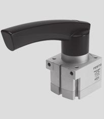
114
115
116
117

118 Solenoid Valves VUVG Overview Universal valve Combination of basic valve and E-boxes Width 0 mm and 4 mm In-line valves VUVG-L and VUVG-S Sub-base valves VUVG-B Internal or external pilot air supply Can be mounted as individual valve or sub-base valve on sturdy aluminum manifold rail Operating voltage 5, 2 and 24 V DC Detailed product information Valves and Valve Manifolds 3 Product Range Overview Type Design Working line Width Valve functions and flow rates [l/min] Page/ T32C T32U T32H M52 B52 P53C P53U P53E Internet Lead Time LT: D typically ships same day/next day VUVG-L In-line valve M7 on valve Gx on valve Lead Time LT for all following variants: 3D typically ships within 3 days VUVG-L In-line valve M3 on valve vuvg M5 on valve VUVG-S In-line valve for manifold assembly M3 on valve M5 on valve M7 on valve Gx on valve VUVG-B Sub-base valve M3 on manifold rail M5 on manifold rail M7 on manifold rail Gx on manifold rail Valve functions: T32C 2x3/2-way valve, normally closed T32U 2x3/2-way valve, normally open T32H 2x3/2-way valve, x normally closed, x normally open M52 B52 5/2-way valve, single solenoid 5/2-way valve, double solenoid P53C P53U 5/3-way valve, mid-position closed 5/3-way valve, mid-position pressurised P53E 5/3-way valve, mid-position exhausted Features Innovative Both internal and external pilot air supply can be used for manifolds with sub-base valves Connection technology easy to change via the E-box Max. pressure 0 bar Versatile Wide range of valve functions Choice of quick plug connectors In-line valves can be used as individual valves or manifold valves M5 and M7 in-line valves can be combined on one manifold rail Identical sub-base valves for M5 or M7 manifold rail Manifolds with pressure zones Reliable Sturdy and durable metal components Fast troubleshooting thanks to 360 LED display Convenient servicing thanks to valves that can be replaced quickly and easily Choice of manual override: non-detenting, detenting or covered Contents VUVG-L0 Technical Data 5 Ordering Data 5 Accessories 7 VUVG-L4 Technical Data 6 Ordering Data 6 Accessories 7 Note: All metric products can be used within inch tubing systems via hybrid fittings ( Overview on page 240) 4 Internet: FAST Program Catalog Subject to change 204/06
119 Solenoid Valves VUVG-L0, In-line Valves M7 Technical Data General Technical Data Download CAD data Valve function 2x3/2-way 5/2-way 5/2-way 5/3-way single solenoid single solenoid double solenoid single solenoid Connection: In-line valve, 2, 3, 4, 5 M7 2, 4 M3 Connection: Manifold rail, 3, 5 GÁ Vacuum operation at port No Only with external pilot air supply Design Piston spool valve Type of mounting Via through-holes ) Length/width/height [mm] 98/0/33 75/0/33 98/0/33 Electrical connection Via E-box Operating voltage [V DC] 5, 2 and 24 ±0% Power [W], reduced to 0.35 with holding current reduction Switching time on/off / Changeover time [ms] 6/6; 7/9; / ; 7 0/30; 6 Duty cycle [%] 00 Protection class to EN IP40 (with plug socket), IP65 (with M8) ) If several valves are to be screwed together via the through-holes to form a block, a minimum gap of 0.3 mm must be ensured by placing spacer discs between them. Operating and Environmental Conditions Valve function 2x3/2-way 5/2-way 5/2-way 5/3-way single solenoid single solenoid double solenoid single solenoid Operating medium Compressed air to ISO 8573-:200 [7:4:4] Note on operating/pilot medium Operation with lubricated medium possible (in which case lubricated operation will always be required) Operating pressure at port with pilot air supply Operating pressure at port 3 or 5 with pilot air supply Internal [bar] External [bar] Internal or [bar] external Pilot pressure ) [bar] Ambient temperature [ C] 5 +50, with holding current reduction Temperature of medium [ C] 5 +50, with holding current reduction ) Minimum pilot pressure 50% of operating pressure. Note on Materials Valves and Valve Manifolds 3 Housing Seals Wrought aluminum alloy HNBR, NBR Ordering Data Code Valve function Internal pilot air supply LT External pilot air supply LT Part No. Type Part No. Type T32C 2x3/2-way valve, normally closed VUVG-L0-T32C-AT-M7-P3 D VUVG-L0-T32C-AZT-M7-P3 D T32U 2x3/2-way valve, normally open VUVG-L0-T32U-AT-M7-P3 D VUVG-L0-T32U-AZT-M7-P3 D T32H 2x3/2-way valve, x normally closed, x normally open VUVG-L0-T32H-AZT-M7-P3 D M52 5/2-way valve, single solenoid VUVG-L0-M52-RT-M7-P3 D VUVG-L0-M52-RZT-M7-P3 D B52 5/2-way valve, double solenoid VUVG-L0-B52-T-M7-P3 D VUVG-L0-B52-ZT-M7-P3 D P53C 5/3-way valve, mid-position closed VUVG-L0-P53C-T-M7-P3 D VUVG-L0-P53C-ZT-M7-P3 D P53U 5/3-way valve, mid-position pressurised VUVG-L0-P53U-T-M7-P3 D VUVG-L0-P53U-ZT-M7-P3 D P53E 5/3-way valve, mid-position exhausted VUVG-L0-P53E-T-M7-P3 D VUVG-L0-P53E-ZT-M7-P3 D Valve and Valve Terminal Configurator A valve terminal configurator is available to help you select further valves VUVG or a suitable valve terminal VTUG. This makes it much easier to order the right product. Valve terminals type 26 VTUG are ordered via an identcode. All valve terminals are supplied fully assembled and individually tested. This reduces assembly and installation time to a minimum Please note: Lead Time LT for configurable variants and options: 3D Download CAD Data Ordering system for valve VUVG Internet: vuvg Ordering system for valve terminal type 26 VTUG Individual electrical connection Internet: vtug LT = Lead time D typically ships same day/next day 3D typically ships within 3 days 204/06 Subject to change FAST Program Catalog Internet: 5
120 Solenoid Valves VUVG-L4, In-line Valves Gx Technical Data General Technical Data Download CAD data Valve function 2x3/2-way 5/2-way 5/2-way 5/3-way single solenoid single solenoid double solenoid single solenoid Connection: In-line valve, 2, 3, 4, 5 Gx 4 M5 Connection: Manifold rail, 3, 5 GÁ Vacuum operation at port No Only with external pilot air supply Design Piston spool valve Type of mounting Optionally via through-holes or on manifold rail Length/width/height [mm] 8/4/35 95/4/35 8/4/35 Electrical connection Via E-box Operating voltage [V DC] 5, 2 and 24 ±0% Power [W], reduced to 0.35 with holding current reduction Switching time on/off / Changeover time [ms] 8/23; 4/28; / ; 8 2/40; 20 Duty cycle [%] 00 Protection class to EN IP40 (with plug socket), IP65 (with M8) ) If several valves are to be screwed together via the through-holes to form a block, a minimum gap of 0.3 mm must be ensured by placing spacer discs between them. Operating and Environmental Conditions Valve function 2x3/2-way 5/2-way 5/2-way 5/3-way single solenoid single solenoid double solenoid single solenoid Valves and Valve Manifolds 3 Operating medium Compressed air to ISO 8573-:200 [7:4:4] Note on operating/pilot medium Operation with lubricated medium possible (in which case lubricated operation will always be required) Operating pressure at port with pilot air supply Operating pressure at port 3 or 5 with pilot air supply Internal [bar] External [bar] Internal or [bar] external Pilot pressure ) [bar] Ambient temperature [ C] 5 +50, with holding current reduction Temperature of medium [ C] 5 +50, with holding current reduction ) Minimum pilot pressure 50% of operating pressure. Note on Materials Housing Seals Wrought aluminum alloy HNBR, NBR Ordering Data Code Valve function Internal pilot air supply LT External pilot air supply LT Part No. Type Part No. Type T32C 2x3/2-way valve, normally closed VUVG-L4-T32C-AT-G8-P3 D VUVG-L4-T32C-AZT-G8-P3 D T32U 2x3/2-way valve, normally open VUVG-L4-T32U-AZT-G8-P3 D T32H 2x3/2-way valve, x normally closed, x normally open VUVG-L4-T32H-AZT-G8-P3 D M52 5/2-way valve, single solenoid VUVG-L4-M52-AT-G8-P3 D VUVG-L4-M52-AZT-G8-P3 D B52 5/2-way valve, double solenoid VUVG-L4-B52-T-G8-P3 D VUVG-L4-B52-ZT-G8-P3 D P53C 5/3-way valve, mid-position closed VUVG-L4-P53C-T-G8-P3 D VUVG-L4-P53C-ZT-G8-P3 D P53U 5/3-way valve, mid-position pressurised VUVG-L4-P53U-T-G8-P3 D VUVG-L4-P53U-ZT-G8-P3 D P53E 5/3-way valve, mid-position exhausted VUVG-L4-P53E-T-G8-P3 D 5665 VUVG-L4-P53E-ZT-G8-P3 D Valve and Valve Terminal Configurator A valve terminal configurator is available to help you select further valves VUVG or a suitable valve terminal VTUG. This makes it much easier to order the right product. Valve terminals type 26 VTUG are ordered via an identcode. All valve terminals are supplied fully assembled and individually tested. This reduces assembly and installation time to a minimum Please note: Lead Time LT for all configurable variants and options: 3D Download CAD Data Ordering system for valve VUVG Internet: vuvg Ordering system for valve terminal type 26 VTUG Individual electrical connection Internet: vtug LT = Lead time D typically ships same day/next day 3D typically ships within 3 days 6 Internet: FAST Program Catalog Subject to change 204/06
121 Solenoid Valves VUVG-S0/4, In-line Valves M5/M7/Gx Accessories Manifold Assembly Ordering Data Accessories Part No. Type 2 4 Manifold rail GÁ 2 valve positions VABM-L-0S-G8-2 4 valve positions VABM-L-0S-G8-4 6 valve positions VABM-L-0S-G8-6 8 valve positions VABM-L-0S-G8-8 2 valve positions VABM-L-0S-G8-2 Manifold rail G¼ 2 valve positions VABM-L-4S-G4-2 4 valve positions VABM-L-4S-G4-4 6 valve positions VABM-L-4S-G4-6 8 valve positions VABM-L-4S-G4-8 2 valve positions VABM-L-4S-G4-2 2 Blanking plate for manifold rail in-line valves M7 incl. screws and seal VABB-L-0-S 3 in-line valves Gx incl. screws and seal 3 Blanking plug for manifold rail in-line valves M7, separator for pressure zones in-line valves Gx, separator for pressure zones 4 Supply plate for manifold rail in-line valves M7 incl. screws and seal in-line valves Gx incl. screws and seal Seals for in-line valves M7, 0 seals and 20 screws VABB-L VABD-8-B VABD-0-B VABF-L-0-P3A4-M VABF-L-4-P3A4-G VABD-L-0X-S-M7 Valves and Valve Manifolds 3 Gx, 0 seals and 20 screws VABD-L-4X-S-G8 Lead Time LT for all products on this page: D typically ships same day/next day 204/06 Subject to change FAST Program Catalog Internet: 7
122 Solenoid Valves VUVG Accessories E-boxes Accessories Overview 5 System Overview 5 Valves and Valve Manifolds Internet: FAST Program Catalog Subject to change 204/06
123 Solenoid Valves VUVG Accessories Ordering Data E-boxes, connection pattern H, horizontal plug Bipolar W 2/24 V DC VAVE-L-VH2-LP Holding current reduction W 24 V DC VAVE-L-H2-LR 0.35 W Connection pattern H, vertical plug Bipolar W 2/24 V DC VAVE-L-VH3-LP Holding current reduction W 0.35 W 24 V DC VAVE-L-H3-LR 5 Plug socket with cable, open end Straight socket, 2-pin, cable not sheathed Straight socket, 2-pin, cable sheathed Part No. Type 0.5 m NEBV-HG2-KN-0.5-LE2 m NEBV-HG2-KN--LE2 2.5 m NEBV-HG2-KN-2.5-LE2 5 m NEBV-HG2-KN-5-LE2 0.5 m NEBV-HG2-P-0.5-N-LE2 m NEBV-HG2-P--N-LE2 2.5 m NEBV-HG2-P-2.5-N-LE2 5 m NEBV-HG2-P-5-N-LE2 Straight socket, M8, 3-pin 2.5 m NEBU-M8G3-K-2.5-LE3 Inscription label holder Holder for an inscription label, cover for manual override mounting screw 0 pieces ASLR-D-L Valves and Valve Manifolds 3 Lead Time LT for all products on this page: D typically ships same day/next day 204/06 Subject to change FAST Program Catalog Internet: 9
124 Valve Manifolds Type 32 MPA Overview Width 0/20 mm, flow rate up to 700 l/min Modular valve terminal with internal communication system for up to 28 valves Extensive functional integration: pressure sensors, pressure regulators, proportional pressure regulators, electrical voltage zones Mixture of valve sizes possible, simple valve replacement Design optimized for electrical peripherals CPX, extensive electrical networking possible Extensive channel-oriented diagnostics down to the individual valve, integrated condition monitoring and coil current monitoring Detailed product information Valves and Valve Manifolds 3 Key Features Innovative Flexible Reliable Easy to mount Low-profile, high-performance valves in sturdy metal housing MPA flow rate up to 360 l/min MPA2 flow rate up to 700 l/min Standardized from the individual valve up to multi-pin plug and fieldbus connections and control block Dream team: fieldbus valve terminal suitable for electrical peripherals CPX. This means Advanced internal communication system for activation of the valves and CPX modules Diagnosis down to the individual valve Valves can either be activated via electrical isolation or without (standard) Modular system offering a range of configuration options Expandable up to 28 solenoid coils Up to 24 valve positions with multi-pin plug connection, and up to 64 valve positions with fieldbus connection (CPX terminal) Can be easily modified in the field Manifold sub-bases can be expanded using just three screws and sturdy separating seals on metal separator plates Integration of innovative function modules possible Supply plates permit a flexible air supply and variable pressure zones High pressure range bar Wide range of valve functions Sturdy and durable metal components Valves Manifold sub-bases Seals Fast troubleshooting thanks to LEDs on the valves and diagnosis via fieldbus High operating voltage tolerance 25% Reliable servicing through replaceable valves and electronics modules Manual override either pushing, detenting or secured against unauthorized activation (covered) Durable thanks to the use of tried-and-tested piston spool valves Large and durable labelling system, suitable for barcodes Ready-to-install unit, already assembled and tested Lower costs for selection, ordering, assembly and commissioning Secure wall mounting or H-rail mounting Contents Options Overview 2 Technical Data 23 Ordering Data 25 Accessories Overview 26 Note: All metric products can be used within inch tubing systems via hybrid fittings ( Overview on page 240) 20 Internet: FAST Program Catalog Subject to change 204/06
125 Valve Manifolds Type 32 MPA Overview Valve Types M J N 5/2-way valve, single solenoid 5/2-way valve, double solenoid 2x 3/2-way valve, normally open B G 5/3-way valve, mid-position pressurized 5/3-way valve, mid-position closed I 2x 2/2-way valve, x normally closed, x normally closed, reversible P Q PG Manual pressure regulators Proportional pressure regulators External pressure sensor K H 2x 3/2-way valve, normally closed 2x 3/2-way valve, x normally open, x normally closed E D 5/3-way valve, mid-position exhausted 2x 2/2-way valve, normally closed X W x 3/2-way valve, normally closed, external compressed air supply x 3/2-way valve, normally open, external compressed air supply L Blanking plate for vacant valve position A, B, H Electronics module for fieldbus with extended diagnostic function Electrical Connection Options Multi-pin plug connection Control signals from the controller to the valve terminal are transmitted via a pre-assembled multi-wire cable or a self-assembly multi-pin plug connection, which substantially reduces installation time. The valve manifolds can be fitted with max. 24 solenoid coils. This corresponds to 4 to 24 MPA or 2 to 24 MPA2 valves, or a combination of both. Variants Sub-D connection Multi-pin cable, pre-assembled Multi-pin plug connection, for self-assembly Fieldbus connection from the CPX system Fieldbus Variants An integrated fieldbus node manages the communication connection to a higher-order PLC. This enables a space-saving pneumatic and electronic solution. Valve manifolds with fieldbus interfaces can be configured with up to 6 manifold sub-bases. In conjunction with MPA and 8 solenoid coils per manifold sub-base, up to 28 solenoid coils can thus be activated. In conjunction with MPA2, 2 to 64 valves can be actuated. Profibus-DP ProfiNet Interbus DeviceNet connection CANopen CC-Link Ethernet/IP EtherCAT Front End Controller Remote Front End Controller Remote I/O Modbus/TCP Profinet IO CPX-Terminal Valves and Valve Manifolds 3 Control block connection from the CPX system Controllers integrated in the Festo valve manifolds permit the construction of stand-alone control units to IP65, without control cabinets. Using the slave operation mode, these valve manifolds can be used for intelligent pre-processing and are therefore ideal modules for designing decentralized intelligence. In the master operation mode, terminal groups can be designed with many options and functions, which can autonomously control a medium-sized machine/system. Special features Multi-pin terminal Max. 24 valve positions/ max. 24 solenoid coils Parallel modular valve linking via circuit boards Electronics module with integrated holding current reduction Any compressed air supply Any number of pressure zones Fieldbus terminal/control block Max. 64 valve positions/ max. 28 solenoid coils Internal CPX bus system for valve activation Module for electrical valve activation, with or without electrical isolation Any compressed air supply Any number of pressure zones Individual valve Electrical M8 connection, 4-pin with screw connection Detachable electronics module with integrated holding current reduction Combinable MPA flow rate up to 360 l/min MPA2 flow rate up to 700 l/min MPA and MPA2 can be combined on one valve terminal 204/06 Subject to change FAST Program Catalog Internet: 2
126 Valve Manifolds Type 32 MPA Overview Modular Pneumatic Components The modular design of the MPA facilitates maximum flexibility right from the planning stage and offers maximum ease of service in operation. The system consists of manifold sub-bases and valves. The manifold sub-bases are screwed together and thus form the support system for the valves. Contained inside these sub-bases are the connection ducts for supplying compressed air to and venting from the valve terminal as well as the working ports to the pneumatic cylinders from each valve. Each manifold sub-base is connected to the next using three screws. Individual terminal sections can be isolated and further sub-bases inserted by loosening these screws. This ensures that the valve terminal can be rapidly and reliably expanded. Valves and Valve Manifolds 3 Modular Electrical Peripherals The manner in which the valves are activated differs according to whether you are using a multi-pin terminal, fieldbus terminal or individual valve. The MPA with CPX interface is based on the internal bus system of the CPX and uses this serial communication system for all solenoid coils and a range of electrical input and output functions. Serial linking facilitates the following: Transmission of switching information High valve density Compact design Position-based diagnosis Separate voltage supply for valves Flexible conversion without address shifting Transmission of status, parameter and diagnostic data Option of CP interface CPX-FEC as autonomous controller with access via Ethernet and web server MPA with Electrical Peripherals CPX Modularity with Electrical Peripherals CPX 22 Internet: FAST Program Catalog Subject to change 204/06


127 Valve Manifolds Type 32 MPA Technical Data Valve Terminal with Multi-pin Plug or Fieldbus Connection Flow rate: MPA: up to 360 l/min MPA2: up to 700 l/min Valve width: MPA: 0 mm MPA2: 20 mm Voltage: 24 V DC Materials Connection block, valve, supply plate, right-hand end plate, left-hand pneumatic interface: Die-cast aluminum Seals: NBR, elastomer Exhaust plate: Polyamide Flat plate silencer: Polyethylene Electronics module: Polycarbonate Electrical manifold module: Bronze/polybutylene terephthalate General Technical Data MPA MPA2 Constructional design Electromagnetically actuated piston spool valve Nominal size [mm] 2.5 Lubrication Lubrication for life, PWIS-free (free of paint-wetting impairment substances) Type of mounting Wall mounting On H-rail to EN 6075 Standard nominal flow rate [l/min] Max. 360 Max. 700 Manual override Non-detenting, rotary/detenting, covered Pneumatic connections Pneumatic connection Via manifold sub-base Supply port G¼ Exhaust port 3/5 QS-0 Working ports 2/4 Depending on the connection type selected M7 Gx QS4 QS6 QS6 QS8 Pilot air supply port 2/4 M7 Pilot exhaust air port 82/84 M7 Pressure relieving port With ducted exhaust air: via port 82/84 (M5 with individual sub-base) With flat plate silencer: venting to atmosphere Valves and Valve Manifolds 3 Valve Switching Times [ms] Valve function order code M J N K H B G E X W D I KS DS MPA Switching times on off changeover 5 MPA2 Switching times on off changeover /06 Subject to change FAST Program Catalog Internet: 23
128 Valve Manifolds Type 32 MPA Technical Data Operating and Environmental Conditions Valve function order code M J N K H B G E X W D I KS DS Operating medium Compressed air in accordance with ISO 8573-:200 [7:4:4] Note on operating/pilot medium Operation with lubricated medium possible (in which case lubricated operation will always be required) Grade of filtration [μm] 40 Operating pressure [bar] Operating pressure for valve terminal with [bar] 3 8 internal pilot air supply Pilot pressure [bar] 3 8 Ambient temperature [ C] Temperature of medium [ C] Storage temperature ) [ C] Relative air humidity at 40 C [%] 90 ) Long-term storage Electrical Data MPA with CPX Terminal Valves and Valve Manifolds 3 Voltage supply for electronics (U EL/SEN ) Nominal voltage [V] 24 DC Operating voltage range [V] 8 30 DC Steady state current consumption at 24 V DC [ma] 20 Load voltage supply for valves (Uval) Nominal voltage [V] 24 DC Operating voltage range [V] 8 30 DC Max. intrinsic current consumption at 24 V (regardless of the switching status of the valves) per electronics module VMPA-FB-EMS-8 or VMPA2-FB-EMS-4 VMPA-FB-EMG-8 or VMPA2-FB-EMG-4 Diagnostic message on undervoltage U OFF Load voltage outside function range Protection class to EN [ma] [ma] 8 not electrically isolated (max. signal line length 0 m) 25 electrically isolated [V] IP65 (for all types of signal transmission in assembled state) Max. current consumption per solenoid coil at nominal voltage MPA MPA2 Nominal pull current/duration [ma] 45/20 ms 90/20 ms Nominal current with current reduction [ma] 8 after 20 ms 8 after 20 ms Calculation example Current consumption with two solenoid coils MPA2 switched in [ma] I El/SEN = 20 parallel and one electronics module without electrical isolation Nominal pull current [ma] I VAL = x 90 = 88 Nominal current with current reduction [ma] I VAL = x 8 = 44 Electrical Data MPA with Multi-pin Plug Connection Nominal voltage [V] 24 DC Operating voltage range [V] 8 30 DC Residual ripple 4 Vss Current consumption at Sub-D multi-pin plug connection MPA MPA2 per solenoid coil at nominal voltage Nominal pull current/duration [ma] 80/25 ms 00/50 ms Nominal current with current reduction [ma] 25 after 25 ms 20 after 50 ms 24 Internet: FAST Program Catalog Subject to change 204/06


129 Valve Manifolds Type 32 MPA Ordering Data Valve Terminal Configurator The appropriate MPA valve terminal can be chosen quickly and easily using the online catalog. This includes an easy-to-use valve terminal configurator, which makes it much easier for you to find the right product. The valve manifolds are fully assembled according to your order specifications and are individually tested. This reduces assembly and installation time to a minimum. You order a valve terminal type 32 using the order code. Ordering system for type 32 Internet: mpa Ordering system, CPX Internet: cpx The illustration above provides an example of a valve terminal configuration. The following steps explain how you arrive at the order code: Once you have called up click on Products tab and then select the Catalog tab on the left hand side of the Products page. Now select Valve Manifolds and then Valve Manifolds. Select your desired valve terminal (in this case MPA-S) and then finally click on link of the product with the desired actuation methodology. You can then configure the valve terminal step by step (from left to right) according to your requirements. Now click on the Add to basket option to save the selected configuration (this will not trigger an order). Valves and Valve Manifolds 3 2D/3D CAD Data You can request the CAD data for a valve terminal you have configured by selecting the 2D/3D view option under the Add to basket option in the valve terminal configurator. You can generate a 3D preview or request an or download of a CAD model in the format of your choice. Lead Time LT for all configurable options on this page: 3D typically ships within 3 days 204/06 Subject to change FAST Program Catalog Internet: 25
130 Valve Manifolds Type 32 MPA Accessories System Overview aa ab aj ai aa ac aj ad bj ab aj ae Valves and Valve Manifolds 8 ah ae aj ad 3 8 ag af ae Accessories Inscription label, large 2 Flat plate silencer 3 Exhaust plate for ducted exhaust air 4 Electronics module MPA or MPA2 5 Valve MPA or MPA2 6 Cover for manual override (pushing, covered only) 7 Blanking plate for vacant valve position 8 H-rail mounting/mounting bracket for wall mounting 9 Right-hand end plate aj Separating seal Accessories aa Electrical manifold module ab Inscription label holder for manifold sub-base, 4-fold ac Supply plate ad Threaded connectors for working ports ae Push-in fittings for supply connections af Pneumatic interface (CPX interface) ag CPX modules ah Electrical interface (multi-pin plug) ai Multi-pin plug connection with multi-pin cable and/or for self-assembly bj Individual sub-base 26 Internet: FAST Program Catalog Subject to change 204/06
131 Valve Manifolds Type 0 CPV, Compact Performance Overview Width 0/4 mm, flow rate up to 800 l/min Maximum flow with minimum space requirement Mounting on site: short tubing lengths, short cycle times Extensive range of valve functions, comprehensive electrical connection concept, extensive electrical networking possible Pneumatic multiple connector plate for machine mounting and control cabinet Detailed product information Key Features Innovative Flexible Reliable Easy to mount Cubic design for exceptional performance and low weight Low installation and bus connection costs Decentralized machines and system structures, for example in handling technology in conveyor technology in the packaging industry in sorting systems in upstream machine functions Integrated diagnosis, condition monitoring (Fieldbus Direct) Flexible and cost-effective connection of 2 to 8 valve slices Highly flexible thanks to: various pneumatic functions (valve variants) different pressure ranges vacuum switches integrated vacuum generation relay plates with floating electrical outputs Separator plates for the formation of pressure zones Blanking plates for future expansion LED displays Manual valve overrides Protection class to IP65 CE, UL symbol Ready-to-install unit, already assembled and tested Lower costs for selection, ordering, assembly and commissioning Secure wall mounting or H-rail mounting Pneumatic multi-connector plate fast assembly without the need to replace fitted tubing Assembly optimized for control cabinets Valves and Valve Manifolds 3 Valve Types M J N C H 5/2-way single solenoid valve 5/2-way valve, double solenoid 2x 3/2-way valve, normally open 2x 3/2-way valve, normally closed 2x 3/2-way valve, x normally open, x normally closed G D I F 5/3-way valve, mid-position closed 2x 2/2-way valve, normally closed 2x 2/2-way valve, x normally open, x normally closed 5/2-way single solenoid valve, fast-switching A E P Q Vacuum generator Vacuum generator with ejector pulse One-way flow control valve, 2x supply air One-way flow control valve, 2x exhaust air V One-way flow control valve for vacuum T Plate with duct separation / closed S Plate with duct separation / and 3/5 closed L Vacant position R Relay plate Contents Options Overview 28 Technical Data 30 Ordering Data 32 Accessories Overview 33 Note: All metric products can be used within inch tubing systems via hybrid fittings ( Overview on page 240) 204/06 Subject to change FAST Program Catalog Internet: 27
132 Valve Manifolds Type 0 CPV, Compact Performance Overview Advantages at a Glance The CPV valve terminal is of unique design. It permits the flexible combination of pneumatic performance, electrical connection technologies and a wide range of mounting options. The generously sized flow ducts and powerful flat plate silencers ensure high flow rates. This means that even comparatively large pneumatic cylinders can be driven with ease. All valves are in the form of valve slices. They are optimized for flow performance and are also extremely compact. Two functions per valve slice (e.g. 2x 3/2-way valves) mean that twice the component density can be achieved. This saves space and reduces costs. The cubic design permits exceptional performance yet a comparatively low weight. The benefits of this design are obvious when the valve terminal is used on a moving installation. However robustness must not be sacrificed in favor of compactness. The connecting thread and mounting attachments are metallic. The manual override for the valves can be adapted for different operating situations. If, for example, a detenting manual override is required for setting-up mode, the manual override can be easily converted for that application in a way that rules out operational errors. The clear, large labelling system also contributes to the safe operation of the valve terminal. A particular plus is the range of electrical connection technologies supported. All types of valve activation are possible, from individual valve connections up to bus systems with versatile expansion options. The integration of electrical input and output modules permits cost-effective solutions within the different installation concepts. Made-to-measure pneumatics Variable compressed air supply Easy assembly technology Exceptional performance and low weight Blanking plates for future expansion LED displays Manual valve overrides Low installation and bus connection costs Protection class to IP65 Variable compressed air supply that can be adapted to the relevant requirements Modules for additional compressed air supply and exhaust Choice of assembly on H-rail or profile/backwall Adaptable assembly with connectors for different tubing diameters Design Principle The cubic design provides a clearly assigned function on each side. Thus, for example, the electrical connection is mounted on the top surface. An optional inscription label holder can be placed on the front of the valve terminal. The different combination options ensure Valves and Valve Manifolds the optimum solution for the task at hand. Pneumatic supply connections on the left, right or underneath Pneumatic working ports and functional modules (vertical stacking) underneath Manual operation/identification on the front Electrical connection surface on the top Mounting surface at the back or even at the front via a pneumatic multi-connector plate 3 Valves CPV valves are integrated sub-base valves, i.e. in addition to the valve function they contain all of the pneumatic ducts for supply, exhaust and the working ports. The supply ducts are a central component of the valve slices and allow a direct flow of air through the valve slices. This helps achieve maximum flow rates. All valves have pneumatic pilot control for optimising performance. The valve function is based on a piston spool system with a patented sealing principle that guarantees its suitability for a wide range of applications as well as a long service life. The pneumatic components and functions are always identical for all actuator types. Most functions are also available in the various valve sizes (spacing). Restrictions are noted where applicable. Pressure zones Different pressures at port and result in two pressure levels per valve. This means, for example, that a cylinder drive can be extended with high pressure and retracted with low pressure to save energy. The maximum number of pressure zones possible is determined by the combination of the following components: Use of a separator plate End plate pair type Valve slice type You can divide the CPV valve terminal into 2 to 4 pressure zones by using separator plates. 28 Internet: FAST Program Catalog Subject to change 204/06
133 Valve Manifolds Type 0 CPV, Compact Performance Overview Electrical Connection Options General Current reduction CPV0/4 valves are activated by means of an integrated current reduction circuit, which reduces power consumption and heat build-up. This current reduction circuit is integrated in the electrical interface unit (multi-pin plug or fieldbus connection) or in the individual connecting cable. During switch-off, the voltage peaks are limited to 38 V DC. Contacts which are fitted on the top of the valve slice form the interface for various electrical connection options. The electrical connection is attached from above using four screws. This means that the valve terminal can be adapted to different electrical requirements or fieldbus protocols using the same pneumatic part. I [ma] t [ms] Multi-pin plug connection Control signals from the controller to the valve terminal are transmitted via a pre-assembled multi-wire cable, which substantially reduces installation time. This valve terminal can be equipped with 4 to 6 solenoid coils (4, 6 or 8 valve slices). Fieldbus Direct Fieldbus Fieldbus Direct is a system for the compact connection of a CPV, CPV-SC, CPA-SC or CDVI valve terminal to different fieldbus standards such as Profibus and DeviceNet. The fieldbus node is directly integrated in the electrical actuation of the valve terminal and therefore takes up only a minimal amount of space. The CP string extension option allows the functions and components of the CPI installation system to be used. Instead of an output module with 8 digital outputs, a valve terminal with 4, 6 or 8 valve slices (4 to 6 solenoid coils per terminal) can be used. Valves and Valve Manifolds 3 Pneumatic Connection The working ports are located directly in the valve slices. Threaded connections and Quick Star push-in fittings (QS) are available for different tubing sizes. The supply ports are located in the end plates or in the pneumatic multi-connector plate. Push-in fittings are available fully assembled. The following working ports can be selected (values in brackets apply for CPV 4): QS-6(8) push-in fittings: Code A QS-4(6) push-in fittings: Code B Threaded connections M7(GÁ): Code C QS ¼(Ä) Push-in fittings: Code D QS Â(¼) Push-in fittings: Code E 204/06 Subject to change FAST Program Catalog Internet: 29
134 Valve Manifolds Type 0 CPV, Compact Performance Technical Data Valve Terminal with Multi-pin Plug or Fieldbus Connection Flow rate: CPV0: 400 l/min CPV4: 800 l/min Valve width: CPV0: 0 mm CPV4: 4 mm Voltage: 24 V DC Materials Basic electrical unit: Die-cast aluminum, polyamide, nitrile rubber Valve slices: Die-cast aluminum Valve module 5/3G: Cast aluminum, polyacetate Blanking plate/separator plate: Polyamide End plates: Die-cast aluminum Flat plate silencer: Die-cast aluminum, polyethylene Pneumatic multi-connector plate: Wrought aluminum alloy Inscription label holder: Polyacetate, polyvinyl chloride Seal: Nitrile rubber General Technical Data Size 0 4 Valves and Valve Manifolds 3 Constructional design Piston slide Width [mm] 0 4 Nominal size [mm] 4 6 Lubrication Lubrication for life, PWIS-free (free of paint-wetting impairment substances) Type of mounting Via pneumatic multi-connector plate Via backwall On H-rail Standard nominal flow rate [l/min] Pneumatic connections Pneumatic connection Via end plate Supply port / Gx G¼ Exhaust port 3/5 Gy (G¼) ) G½ (Gy) ) Working ports 2/4 M7 Gx Pilot air port 2/4 M5 (M7) ) G¼ Pilot exhaust air port 82/84 M5 (M7) ) Gx Electrical connection Operating voltage [V] 24 DC (+0/ 5%) 24 DC (+0/ 5%) Electrical power consumption [W] 0.6 (0.45 at 2 V); (0.65 with CPV0-MH- ) 0.9 (0.65 at 2 V) ) Connection dimensions in brackets for pneumatic multi-connector plate 30 Internet: FAST Program Catalog Subject to change 204/06
135 Valve Manifolds Type 0 CPV, Compact Performance Technical Data Valve Response Times [ms] Valve function order code M F J N C CY H G D I A E CPV0 Switching times on off changeover 0 CPV4 Switching times on off changeover 2 Operating and Environmental Conditions Valve function order code M F J N C CY H G D I A E Operating medium Compressed air in accordance with ISO 8573-:200 [7:4:4] Note on operating/pilot medium Operation with lubricated medium possible (in which case lubricated operation will always be required) Grade of filtration [μm] 40 (average pore size) Operating pressure [bar] Operating pressure [bar] 3 8 for valve terminal with internal pilot air supply Pilot pressure [bar] 3 8 Ambient temperature [ C] (vacuum generators: 0 +50) Storage temperature [ C] Relative air humidity at 25 C [%] 95 with no condensation Corrosion resistance class CRC ) 2 ) Corrosion resistance class 2 as per Festo standard Components subject to moderate corrosion stress. Externally visible parts with primarily decorative surface requirements which are in direct contact with a normal industrial environment or media such as coolants or lubricating agents. Valves and Valve Manifolds 3 204/06 Subject to change FAST Program Catalog Internet: 3

136 Valve Manifolds Type 0 CPV, Compact Performance Ordering Data Valve Terminal Configurator Valves and Valve Manifolds 3 A valve terminal configurator is available to help you select a suitable valve terminal CPV. This makes it much easier for you to find the right product. The valve manifolds are fully assembled according to your order specifications and individually tested. This reduces assembly and installation time to a minimum. You order a valve terminal type 0 using the order code. Ordering system for type 0 Internet: cpv Ordering system, CPX Internet: cpx The illustration above provides an example of a valve terminal configuration. The following steps explain how you arrive at the order code: Once you have called up click on Products tab and then select the Catalog tab on the left hand side of the Products page. Now select Valve Manifolds and then Valve Manifolds. Select your desired valve terminal (in this case CPV) and then finally click on link of the product with the desired actuation methodology. You can then configure the valve terminal step by step (from left to right) according to your requirements. Now click on the Add to basket option to save the selected configuration (this will not trigger an order). 2D/3D CAD Data You can request the CAD data for a valve terminal you have configured by selecting the 2D/3D view option under the Add to basket option in the valve terminal configurator. You can generate a 3D preview or request an or download of a CAD model in the format of your choice. Lead Time LT for all configurable options on this page: 3D typically ships within 3 days 32 Internet: FAST Program Catalog Subject to change 204/06
137 Valve Manifolds Type 0 CPV, Compact Performance Accessories System Overview ac ab 2 aa Valves and Valve Manifolds aj Accessories Basic electrical unit (Fieldbus Direct, CPI installation system, AS-interface, multi-pin plug connection) 2 Right-hand end plate with flat plate silencer 3 Comprehensive valve functions 4 Right-hand end plate (threaded connections not in combination with pneumatic multi-connector plate) 5 Inscription label holder 6 QS push-in fittings Accessories 7 Functional module (vertical stacking) 8 Pneumatic multi-connector plate 9 Left-hand end plate (threaded connections not in combination with pneumatic multi-connector plate) aj Left-hand end plate with flat plate silencer aa Attachment for H-rail ab Attachment for wall mounting ac Plug for electrical connection 204/06 Subject to change FAST Program Catalog Internet: 33
138 Valve Manifolds Type 44 VTSA, Type 45 VTSA-F Inch Series Overview Modular multi-functional valve manifold for up to 32 valves: Type 44 VTSA, ISO /ISO Type 45 VTSA-F with optimized flow Different valve sizes on one valve manifold: 0.7 in (ISO 02).02 in (ISO 0).65 in (IS0 ), type 44 VTSA only 2.05 in (IS0 2), type 44 VTSA only Flow rate: up to 02 scfm Pneumatic connections with threaded connector or QS fitting Design optimized for electrical peripherals CPX Detailed product information Valves and Valve Manifolds 3 Product Range Overview Electrical connection Electrical multi-pin plug connection, CageClamp Electrical multi-pin plug connection, Sub-D (37-pin) Fieldbus connection/control block Valve types 5/2-way valve, single solenoid with pneumatic spring return 5/2-way valve, single solenoid with spring return 5/2-way valve, double solenoid 5/2-way valve, double solenoid dominant switching 2x 3/2-way valve, normally open 2x 3/2-way valve, normally closed 2x 3/2-way valve: x normally open, x normally closed 5/3-way valve, mid-position pressurized 5/3-way valve, mid-position closed 5/3-way valve, mid-position exhausted 2x 3/2-way valve, normally open, reverse operation 2x 3/2-way valve, normally closed, reverse operation 2x 3/2-way valve: x normally open, x normally closed, reverse operation M O J D N K H B G E P Q R L Blanking plate for vacant position Key Features Multi-pin plug manifold Fieldbus manifold/control block Comprehensive Combinable Max. 32 valve positions/ max. 32 solenoid coils Parallel modular valve linking via circuit boards Any compressed-air supply Any number of pressure zones Max. 32 valve positions/ max. 32 solenoid coils Any compressed-air supply Any number of pressure zones Width 0.7 in (ISO Size 02): valve flow rate up to 24.7 scfm Width.02 in (ISO Size 0): valve flow rate up to 49.4 scfm Width.65 in (ISO Size ): valve flow rate up to 53 scfm Width 2.05 in (ISO Size 2): valve flow rate up to 02 scfm Width 0.7 in (Size 02),.02 in (Size 0),.65 in (Size ) and 2.05 in (Size 2) can be combined on a single valve manifold Contents Options Overview 35 Technical Data 37 Ordering Data 40 Accessories Overview Internet: FAST Program Catalog Subject to change 204/06
139 Valve Manifolds Type 44 VTSA, Type 45 VTSA-F Inch Series Overview Flexible Easily Integrated Comprehensive Installation and Maintenance Easy modification and expansion due to high degree of modularity. Fast connection of the subbases by means of four screws. Fully modular system allows the combination of 0.7 in (Size 02),.02 in (Size 0),.65 in (Size ) and 2.05 in (Size 2) valves on the same manifold without the need for any transition/adapter plate. Change direction of working ports with easy-to-install angle plate. Fieldbus valve manifold suitable for CPX electrical peripherals. Fieldbus nodes: Interbus, DeviceNet, Profibus DP, CANopen, CC-Link via CPX terminal Ethernet: Modbus/TCP, EtherNet/IP, TCP/IP via CPX terminal Full complement of CPX I/O modules Expandable up to 32 solenoid coils Integration of a wide range of function modules possible Supply plates permit a flexible air supply and variable pressure zones High-performance valves in a sturdy metal housing Complete range of vertical sandwich components such as pressure regulators, flow control valve, individual pressure supply, shutoff plate (hot swap). Standard air qualities: 40 micron filtration grade. Can be used with lubricated or non-lubricated air, and inert gases. Manual override available, with momentary, locking, or hidden (non-accessible) options. Ready-to-install unit, preassembled and tested Durable, low cost identification by label holder on the valve or label holder on the subbase. Secure wall mounting or DIN rail mounting Fast troubleshooting thanks to LEDs on the valves and diagnosis via fieldbus. Reliability of service thanks to valves that can be replaced easily and quickly. Easy fault identification using CPX-MMI handheld diagnostic unit. Electrical Connection Options Multi-pin plug connection Fieldbus connection via the CPX system Control signals from the controller to the valve manifold are transmitted via a pre-assembled multi-core cable or a self-assembled multi-pin plug connection (Cage Clamp), which substantially reduces installation time. An integrated fieldbus node manages the communication connection to a higher-order PLC. This enables a space-saving pneumatic and electronic solution. Valve manifolds with fieldbus interfaces can be configured with up to 6 manifold subbases. With 2 solenoid coils per connection, up to 32 solenoid coils can thus be actuated. The valve manifolds can be fitted with max. 32 valves and max. 32 solenoid coils. Fieldbus Variants Profibus-DP ProfiNet Interbus DeviceNet connection CANopen CC-Link Ethernet/IP EtherCAT Variants Multi-pin plug connection with manifold strip (Cage Clamp) 24 V DC or 0 V AC Pre-assembled connecting cable 24 V DC Sub-D plug connector for fitting by users, 37-pin Front End Controller Remote Front End Controller Remote I/O Modbus/TCP Profinet IO CPX-Terminal Valves and Valve Manifolds 3 Control block connection via the CPX system Controllers integrated in the Festo valve manifolds permit the construction of stand-alone control units to IP65, without control cabinets. Using the slave operation mode, these valve manifolds can be used for intelligent pre-processing and are therefore ideal modules for designing decentralized intelligence. In the master operation mode, manifold groups can be designed with many options and functions, which can autonomously control a medium-sized machine/system. CPX manifold 204/06 Subject to change FAST Program Catalog Internet: 35
140 Valve Manifolds Type 44 VTSA, Type 45 VTSA-F Inch Series Overview Modular Pneumatic Components The modular design of the VTSA/VTSA-F facilitates maximum flexibility right from the planning stage and offers maximum ease of service in operation. The system consists of manifold subbases and valves. The manifold subbases are screwed together and thus form the support system for the valves. Inside, the manifold subbases contain the connection ducts for supplying compressed air to and venting from the valve manifold as well as the working ports for the pneumatic cylinders from each valve. Each manifold subbase is connected to the next using four screws. Individual manifold sections can be isolated and further blocks inserted by loosening these screws. This ensures that the valve manifold can be rapidly and reliably expanded. Modularity in the basic system Modularity in the valves Valves and Valve Manifolds 3 Modular Electrical Peripherals The manner in which the valves are actuated differs according to whether you are using a multi-pin manifold or fieldbus manifold. The VTSA/-VTSA-F with CPX interface is based on the internal bus system of the CPX and uses this communication system for all solenoid coils and a range of electrical input and output functions. Parallel linking facilitates the following: Transmission of switching information High valve density Compact design Position-based diagnosis Separate voltage supply for valves Flexible conversion without address shifting Transmission of status, parameter and diagnostic data VTSA with electrical peripherals CPX Modularity with electrical peripherals CPX 36 Internet: FAST Program Catalog Subject to change 204/06
141 Valve Manifolds Type 44 VTSA, Type 45 VTSA-F Inch Series Technical Data Flow rate Width 0.7 in: Up to 24.7 scfm Width.02 in: Up to 49.4 scfm Width.65 in: Up to 53 scfm Width 2.05 in: Up to 02 scfm Valve width ISO Size 02: 0.7 in (8 mm) ISO Size 0:.02 in (26 mm) ISO Size :.65 in (42 mm) ISO Size 2: 2.05 in (52 mm) Voltage 24 V DC 0 V AC General Technical Data Width 0.7 in.02 in.65 in (type 44 VTSA only) 2.05 in (type 44 VTSA only) Design Lubrication Type of mounting Mounting position Manual override Pneumatic connections Pneumatic connection Electromagnetically actuated piston spool valve Lubrication for life Wall mounting On DIN H-rail to EN 6075 Any Pushing, pushing/detenting, covered NPT thread Via manifold subbase Supply port ½ NPT, QS-½-½-U, QS-½-Æ-U ¾NPT, N-¾-P-9-NPT Exhaust port 3/5 ½ NPT, QS-½-½-U, QS-½-Æ-U ¾NPT, N-¾-P-9-NPT Working ports 2/4 x NPT, QS-x-¼-U, QS-x-Ä-U Port for external pilot 4 ¼ NPT supply air Pilot exhaust air port 2 ¼ NPT Certification ¼ NPT, QS-¼-Ä-U, QS-¼-y-U y NPT, QS-y-y-U, QS-y-½-U ½ NPT, QS-½-½-U Valves and Valve Manifolds 3 Operating and Environmental Conditions Valve function order code M O J D N K H B G E P Q R Operating medium Compressed air in accordance with ISO 8573-:200 [7:4:4] Note on operating/pilot medium Operation with lubricated medium possible (in which case lubricated operation will always be required) Grade of filtration [μm] 40 (average pore size) Operating pressure Pilot pressure [psi] With internal pilot air [psi] With external pilot air [psi] Ambient temperature [ F] Temperature of medium [ F] Storage temperature ) [ F] Relative air humidity [%] 90 ) Long-term storage 204/06 Subject to change FAST Program Catalog Internet: 37
142 Valve Manifolds Type 44 VTSA, Type 45 VTSA-F Inch Series Technical Data Standard Nominal Flow Rate [scfm] Type 44 VTSA Valve function order code M O J D N K H B G E P Q R Width 0.7 in Flow rate of valve ), 5.2 2) 2.2 Flow rate of valve on individual subbase ), 2.7 2) 7.7 Flow rate of valve on valve manifold ), 0.6 2) 4. Width.02 in Flow rate of valve ), ) 44. Flow rate of valve on individual subbase ), ) 35.3 Flow rate of valve on valve manifold ), ) 3.8 Width.65 in Flow rate of valve ), ) 49.4 Flow rate of valve on individual subbase ), ) 42.4 Flow rate of valve on valve manifold ), ) 42.4 Width 2.05 in Flow rate of valve ), 60 2) 05.9 Flow rate of valve on individual subbase ), 60 2) 88.3 Flow rate of valve on valve manifold ), 60 2) 84.7 ) Switching position 2) Mid-position Valves and Valve Manifolds 3 Standard Nominal Flow Rate [scfm] Type 45 VTSA-F Valve function order code M O J D N K H B G E P Q R Width 0.7 in Flow rate of valve ),.6 2) 2.2 Flow rate of valve on valve manifold ),.6 2) 9.4 Width.02 in Flow rate of valve ), ) 44. Flow rate of valve on valve manifold ), ) 40.6 ) Switching position 2) Mid-position Valve Response Times [ms] Valve function order code M O J D N K H B G E P Q R Width 0.7 in Response times on off changeover Width.02 in Response times on off changeover Width.65 in (type 44 VTSA only) Response times on off changeover 6 6 Width 2.05 in (type 44 VTSA only) Response times on off changeover Internet: FAST Program Catalog Subject to change 204/06
143 Valve Manifolds Type 44 VTSA, Type 45 VTSA-F Inch Series Technical Data Electrical Data VTSA/VTSA-F with CPX Manifold 0.7 in.02 in.65 in (Type 44 VTSA only) 2.5 in (Type 44 VTSA only) Voltage supply for electronics/sensors (pin ) Operating voltage [V] 24 DC ±0% Steady state current [ma] 20 consumption at 24 V DC Duty cycle 00% Load voltage supply for valves (pin 2) Operating voltage [V] 24 DC ±0% Diagnostic message [V] undervoltage V OFF, load voltage outside function range Protection class to EN IP65 (for all types of signal transmission in assembled state) Power consumption at 24 V DC 2x 3/2-way valve [W] /2-way valve, 5/3-way valve [W] Electrical Data VTSA/VTSA-F with Multi-pin Plug Connection 0.7 in.02 in.65 in (Type 44 VTSA only) 2.05 in (Type 44 VTSA only) Load voltage supply for valves Operating voltage [V] 24 DC ±0% 0 AC ±0% (50 60 Hz) Duty cycle 00% Protection class to EN IP65 (for all types of signal transmission in assembled state), NEMA 4 Power consumption at 24 V DC 2x 3/2-way valve [W] /2-way valve, 5/3-way valve [W] Power consumption at 0 V AC 2x 3/2-way valve [VA] 5/2-way valve, 5/3-way valve [VA].6 Valves and Valve Manifolds Materials Manifold subbase Valve Seals Supply plate Right-hand end plate Left-hand pneumatic interface Flow control plate Pressure regulator plate Multi-pin connection block Cover for the pneumatic interface and multi-pin plug connection 0.7 in.02 in.65 in (Type 44 VTSA only) 2.05 in (Type 44 VTSA only) Die-cast aluminum Die-cast aluminum, reinforced polyamide Nitrile rubber, elastomer (support made of steel) Die-cast aluminum Die-cast aluminum Die-cast aluminum Die-cast aluminum Die-cast aluminum, reinforced polyamide Die-cast aluminum Wellamid, reinforced polyamide 3 204/06 Subject to change FAST Program Catalog Internet: 39
144 Valve Manifolds Type 44 VTSA, Type 45 VTSA-F Inch Series Ordering Data Valve Manifold Configurator Valves and Valve Manifolds 3 A valve manifold configurator is available to help you select a suitable VTSA/VTSA-F valve manifold. This makes it much easier for you to find the right product. The valve manifolds are fully assembled according to your order specifications and are individually tested. This reduces the amount of assembly and installation to a minimum. You order a valve terminal type 44/45 using the order code. Ordering system for type 44/45 Internet: type 44, type 45 Ordering system, CPX Internet: cpx The illustration above provides an example of a valve terminal configuration. The following steps explain how you arrive at the order code: Once you have called up click on Products tab and then select the Catalog tab on the left hand side of the Products page. Now select Valve Manifolds and then Industry Standard Valve Manifolds. Select your desired valve terminal (in this case VTSA) and then finally click on link of the product with the desired actuation methodology. You can then configure the valve terminal step by step (from left to right) according to your requirements. Now click on the Add to basket option to save the selected configuration (this will not trigger an order). 2D/3D CAD Data You can request the CAD data for a valve terminal you have configured by selecting the 2D/3D view option under the Add to basket option in the valve terminal configurator. You can generate a 3D preview or request an or download of a CAD model in the format of your choice. Lead Time LT for all configurable options on this page: 3D typically ships within 3 days 40 Internet: FAST Program Catalog Subject to change 204/06
145 Valve Manifolds Type 44 VTSA, Type 45 VTSA-F Metric Series Overview Modular multi-functional valve manifold for up to 32 valves: Type 44 VTSA, ISO /ISO Type 45 VTSA-F with optimized flow Different valve sizes on one valve manifold: 8 mm (ISO 02) 26 mm (ISO 0) 42 mm (IS0 ), type 44 VTSA only 52 mm (IS0 2), type 44 VTSA only Flow rate: up to 2,900 l/min Pneumatic connections with threaded connector or QS fitting Design suitable for electrical peripherals CPX Detailed product information Product Range Overview Electrical connection Electrical multi-pin plug connection, CageClamp Electrical multi-pin plug connection, Sub-D (37-pin) Fieldbus connection/control block Valve types 5/2-way valve, single solenoid with pneumatic spring return 5/2-way valve, single solenoid with spring return 5/2-way valve, double solenoid 5/2-way valve, double solenoid dominant switching 2x 3/2-way valve, normally open 2x 3/2-way valve, normally closed 2x 3/2-way valve: x normally open, x normally closed 5/3-way valve, mid-position pressurized 5/3-way valve, mid-position closed 5/3-way valve, mid-position exhausted 2x 3/2-way valve, normally open, reverse operation 2x 3/2-way valve, normally closed, reverse operation 2x 3/2-way valve: x normally open, x normally closed, reverse operation M O J D N K H B G E P Q R L Blanking plate for vacant position Valves and Valve Manifolds 3 Key features Multi-pin plug manifold Fieldbus manifold/control block Comprehensive Combinable Max. 32 valve positions/ max. 32 solenoid coils Parallel modular valve linking via circuit boards Any compressed-air supply Any number of pressure zones Max. 32 valve positions/ max. 32 solenoid coils Any compressed-air supply Any number of pressure zones 8 mm (ISO Size 02): Valve flow rate up to 550 l/min 26 mm (ISO Size 0): Valve flow rate up to,00 l/min 42 mm (ISO Size ): valve flow rate up to,500 l/min 52 mm (ISO Size 2): valve flow rate up to 2,900 l/min Width 8 mm (Size 02), 26 mm (Size 0), 42 mm (Size ) and 52 mm (Size 2) can be combined on a single valve manifold Contents Note: All metric products can be used within inch tubing systems via hybrid fittings ( Overview on page 240) Options Overview 42 Technical Data 44 Ordering Data 47 Accessories Overview /06 Subject to change FAST Program Catalog Internet: 4
146 Valve Manifolds Type 44 VTSA, Type 45 VTSA-F Metric Series Overview Flexible Easily integrated Comprehensive Installation and maintenance Easy modification and expansion due to high degree of modularity. Fast connection of the subbases by means of four screws. Fully modular system allows the combination of 8 mm (Size 02), 26 mm (Size 0), 42 mm (Size ) and 52 mm (Size 2) valves on the same manifold without the need for any transition/adapter plate. Change direction of working ports with easy-to-install angle plate. Fieldbus valve manifold suitable for CPX electrical peripherals. Fieldbus nodes: Interbus, DeviceNet, Profibus DP, CANopen, CC-Link via CPX terminal Ethernet: Modbus/TCP, EtherNet/IP, TCP/IP via CPX terminal Full complement of CPX I/O modules Expandable up to 32 solenoid coils Integration of a wide range of function modules possible Supply plates permit a flexible air supply and variable pressure zones High-performance valves in a sturdy metal housing Complete range of vertical sandwich components such as pressure regulators, flow control valve, individual pressure supply, shutoff plate (hot swap). Standard air qualities: 40 micron filtration grade. Can be used with lubricated or non-lubricated air, and inert gases. Manual override available, with momentary, locking, or hidden (non-accessible) options. Ready-to-install unit, preassembled and tested Durable, low cost identification by label holder on the valve or label holder on the subbase. Secure wall mounting or DIN rail mounting Fast troubleshooting thanks to LEDs on the valves and diagnosis via fieldbus. Reliability of service thanks to valves that can be replaced easily and quickly. Easy fault identification using CPX-MMI handheld diagnostic unit. Electrical connection options Multi-pin plug connection Valves and Valve Manifolds 3 Fieldbus connection via the CPX system Control signals from the controller to the valve manifold are transmitted via a pre-assembled multi-core cable or a self-assembled multi-pin plug connection (Cage Clamp), which substantially reduces installation time. An integrated fieldbus node manages the communication connection to a higher-order PLC. This enables a space-saving pneumatic and electronic solution. Valve manifolds with fieldbus interfaces can be configured with up to 6 manifold subbases. With 2 solenoid coils per connection, up to 32 solenoid coils can thus be actuated. The valve manifolds can be fitted with max. 32 valves and max. 32 solenoid coils. Fieldbus Variants Profibus-DP ProfiNet Interbus DeviceNet connection CANopen CC-Link Ethernet/IP EtherCAT Variants Multi-pin plug connection with manifold strip (Cage Clamp) 24 V DC or 0 V AC Pre-assembled connecting cable 24 V DC Sub-D plug connector for fitting by users, 37-pin Front End Controller Remote Front End Controller Remote I/O Modbus/TCP Profinet IO CPX-Terminal Control block connection via the CPX system Controllers integrated in the Festo valve manifolds permit the construction of stand-alone control units to IP65, without control cabinets. Using the slave operation mode, these valve manifolds can be used for intelligent pre-processing and are therefore ideal modules for designing decentralized intelligence. In the master operation mode, manifold groups can be designed with many options and functions, which can autonomously control a medium-sized machine/system. CPX manifold 42 Internet: FAST Program Catalog Subject to change 204/06
147 Valve Manifolds Type 44 VTSA, Type 45 VTSA-F Metric Series Overview Modular Pneumatic Components The modular design of the VTSA/VTSA-F facilitates maximum flexibility right from the planning stage and offers maximum ease of service in operation. The system consists of manifold subbases and valves. The manifold subbases are screwed together and thus form the support system for the valves. Inside, the manifold subbases contain the connection ducts for supplying compressed air to and venting from the valve manifold as well as the working ports for the pneumatic cylinders from each valve. Each manifold subbase is connected to the next using four screws. Individual manifold sections can be isolated and further blocks inserted by loosening these screws. This ensures that the valve manifold can be rapidly and reliably expanded. Modularity in the basic system Modularity in the valves Modular Electrical Peripherals The manner in which the valves are actuated differs according to whether you are using a multi-pin manifold or fieldbus manifold. The VTSA/VTSA-F with CPX interface is based on the internal bus system of the CPX and uses this communication system for all solenoid coils and a range of electrical input and output functions. Parallel linking facilitates the following: Transmission of switching information High valve density Compact design Position-based diagnosis Separate voltage supply for valves Flexible conversion without address shifting Transmission of status, parameter and diagnostic data Valves and Valve Manifolds 3 VTSA with electrical peripherals CPX Modularity with electrical peripherals CPX 204/06 Subject to change FAST Program Catalog Internet: 43
 52 mm (type 44 VTSA")
148 Valve Manifolds Type 44 VTSA, Type 45 VTSA-F Metric Series Technical Data Flow rate Width 8 mm: Up to 700 l/min Width 26 mm: Up to,400 l/min Width 42 mm: Up to,500 l/min Width 52 mm: Up to 2,900 l/min Valve width ISO Size 02: 8 mm ISO Size 0: 26 mm ISO Size : 42 mm ISO Size 2: 52 mm Voltage 24 V DC 0 V AC General Technical Data Width 8 mm 26 mm 42 mm (type 44 VTSA only) 52 mm (type 44 VTSA only) Valves and Valve Manifolds 3 Design Lubrication Type of mounting Mounting position Manual override Pneumatic connections Pneumatic connection Electromagnetically actuated piston spool valve Lubrication for life Wall mounting On DIN H-rail to EN 6075 Any Pushing, pushing/detenting, covered Metric threaded connection Via manifold subbase Supply port G½, QS-G½-2, QS-G½-6 G¾, N-¾-P-9 Exhaust port 3/5 G½, QS-G½-2, QS-G½-6 G¾, N-¾-P-9 Working ports 2/4 Gx, QS-Gx-6, QS-Gx-8 G¼, QS-G¼-8, QS-G¼-0 Gy, QS-Gy-2, QS-Gy-0 G½, QS-½-2, QS-½-6 Port for external pilot supply air 4 G¼ G¼ G¼ G¼ Pilot exhaust air port 2 G¼ G¼ G¼ G¼ Certification Note: This product conforms to ISO 79- and ISO 228- Operating and Environmental Conditions Valve function order code M O J D N K H B G E P Q R Operating medium Compressed air in accordance with ISO 8573-:200 [7:4:4] Note on operating/pilot medium Operation with lubricated medium possible (in which case lubricated operation will always be required) Grade of filtration [μm] 40 (average pore size) Operating pressure Pilot pressure [bar] 3 0 With internal pilot air [bar] 3 0 With external pilot air [bar] Ambient temperature [ C] Temperature of medium [ C] Storage temperature ) [ C] Relative air humidity [%] 90 ) Long-term storage 44 Internet: FAST Program Catalog Subject to change 204/06
149 Valve Manifolds Type 44 VTSA, Type 45 VTSA-F Metric Series Technical Data Standard Nominal Flow Rate [l/min] Type 44 VTSA Valve function order code M O J D N K H B G E P Q R Width 8 mm Flow rate of valve ), 430 2) 600 Flow rate of valve on individual subbase ), 360 2) 500 Flow rate of valve on valve manifold ), 300 2) 400 Width 26 mm Flow rate of valve ), 000 2) 250 Flow rate of valve on individual subbase ), 850 2) 000 Flow rate of valve on valve manifold ), 700 2) 900 Width 42 mm Flow rate of valve ), 750 2) 400 Flow rate of valve on individual subbase ), 800 2) 200 Flow rate of valve on valve manifold ), 800 2) 200 Width 52 mm Flow rate of valve ), 700 2) Flow rate of valve on individual subbase ), 800 2) Flow rate of valve on valve manifold ), 700 2) ) Switching position 2) Mid-position Standard Nominal Flow Rate [l/min] Type 45 VTSA-F Valve function order code M O J D N K H B G E P Q R Width 8 mm Flow rate of valve ), 330 2) 600 Flow rate of valve on valve manifold ), 330 2) 550 Width 26 mm Flow rate of valve ), 700 2) 250 Flow rate of valve on valve manifold ), 700 2) 50 ) Switching position 2) Mid-position Valves and Valve Manifolds 3 Valve Response Times [ms] Valve function order code M O J D N K H B G E P Q R 8 mm Response times on off changeover mm Response times on off changeover mm (type 44 VTSA only) Response times on off changeover mm (type 44 VTSA only) Response times on off changeover /06 Subject to change FAST Program Catalog Internet: 45
150 Valve Manifolds Type 44 VTSA, Type 45 VTSA-F Metric Series Technical Data Electrical Data VTSA/VTSA-F with CPX Manifold 8 mm 26 mm 42 mm (Type 44 VTSA only) 52 mm (Type 44 VTSA only) Voltage supply for electronics/sensors (pin ) Operating voltage [V] 24 DC ±0% Steady state current consumption at [ma] V DC Duty cycle 00% Load voltage supply for valves (pin 2) Operating voltage [V] 24 DC ±0% Diagnostic message undervoltage V OFF, [V] load voltage outside function range Protection class to EN IP65 (for all types of signal transmission in assembled state) Power consumption at 24 V DC 2x 3/2-way valve [W] /2-way valve, 5/3-way valve [W] Electrical Data VTSA/VTSA-F with Multi-pin Plug Connection 8 mm 26 mm 42 mm (Type 44 VTSA only) 52 mm (Type 44 VTSA only) Valves and Valve Manifolds Load voltage supply for valves Operating voltage [V] 24 DC ±0% 0 AC ±0% (50 60 Hz) Duty cycle 00% Protection class to EN IP65 (for all types of signal transmission in assembled state), NEMA 4 Power consumption at 24 V DC 2x 3/2-way valve [W] /2-way valve, 5/3-way valve [W] Power consumption at 0 V AC 2x 3/2-way valve [VA] 5/2-way valve, 5/3-way valve [VA].6 3 Materials Manifold subbase Valve Seals Supply plate Right-hand end plate Left-hand pneumatic interface Flow control plate Pressure regulator plate Multi-pin connection block Cover for the pneumatic interface and multi-pin plug connection 8 mm 26 mm 42 mm (Type 44 VTSA only) 52 mm (Type 44 VTSA only) Die-cast aluminum Die-cast aluminum, reinforced polyamide Nitrile rubber, elastomer (support made of steel) Die-cast aluminum Die-cast aluminum Die-cast aluminum Die-cast aluminum Die-cast aluminum, reinforced polyamide Die-cast aluminum Wellamid, reinforced polyamide 46 Internet: FAST Program Catalog Subject to change 204/06

151 Valve Manifolds Type 44 VTSA, Type 45 VTSA-F Metric Series Ordering Data Valve manifold configurator A valve manifold configurator is available to help you select a suitable VTSA/VTSA-F valve manifold. This makes it much easier for you to find the right product. The valve manifolds are fully assembled according to your order specifications and are individually tested. This reduces the amount of assembly and installation to a minimum. You order a valve terminal type 44/45 using the order code. Ordering system for type 44/45 Internet: type 44, type 45 Ordering system, CPX Internet: cpx The illustration above provides an example of a valve terminal configuration. The following steps explain how you arrive at the order code: Once you have called up click on Products tab and then select the Catalog tab on the left hand side of the Products page. Now select Valve Manifolds and then Industry Standard Valve Manifolds. Select your desired valve terminal (in this case VTSA) and then finally click on link of the product with the desired actuation methodology. You can then configure the valve terminal step by step (from left to right) according to your requirements. Now click on the Add to basket option to save the selected configuration (this will not trigger an order). Valves and Valve Manifolds 3 2D/3D CAD Data You can request the CAD data for a valve terminal you have configured by selecting the 2D/3D view option under the Add to basket option in the valve terminal configurator. You can generate a 3D preview or request an or download of a CAD model in the format of your choice. Lead Time LT for all configurable options on this page: 3D typically ships within 3 days 204/06 Subject to change FAST Program Catalog Internet: 47
152 Valve Manifolds Type 44 VTSA, Type 45 VTSA-F Accessories System Overview Valve Manifold with Multi-pin Plug Connection Order code: 44E for the electrical components 44P for the pneumatic components 45P for the pneumatic components. High flow rate with optimized manifold subbases. Valve manifolds with multi-pin plug connection can be expanded with up to 32 valves with max. 32 solenoid coils. The manifold subbases width 8 and 26 mm are prepared for: 2 single solenoid valves 2 double solenoid valves The manifold subbases width 42 mm are prepared for: single solenoid valve double solenoid valve depending on the size. Double solenoid valve positions can be equipped with any valve or a blanking plate. Single solenoid valve positions can only be equipped with single solenoid valves or a blanking plate. The following multi-pin plug connections to IP65 are available: 37-pin Sub-D connection (24 V DC): The connecting cable can be ordered in lengths of 2.5 m, 5 m and 0 m for max. 8, 22 or 32 solenoid coils. Manifold strip (24 V DC or 0 V AC) ab ac ad ae bj ba bb ah ai Valves and Valve Manifolds aj 8 aa af ae ag ac be bd 7 bc ba bb bf bb cb ca cj bb bf bi bb bb bh bg bf 48 Internet: FAST Program Catalog Subject to change 204/06
153 Valve Manifolds Type 44 VTSA, Type 45 VTSA-F Accessories System Overview Valve Manifold with Multi-pin Plug Connection Brief description Inscription labels Large, for multi-pin plug connection 2 Multi-core cable 3 Exhaust plate Ports 3 and 5 separated 4 Fittings For supply plate 5 Silencer For supply plate 6 Exhaust port cover For ducted exhaust air (ports 3 and 5 combined) 7 Duct separation/seal 8 Manifold subbase For valves with a width of 26 mm 9 Flow control plate aj Vertical supply plate aa Vertical shut-off plate ab Pressure regulator plate ac Cover cap For manual override, pushing, covered ad Valve Width 26 mm ae Inscription label holder For valve af Blanking plate For unused valve position (vacant position) ag Valve Width 8 mm Brief description ah Valve Width 42 mm (type 44 only) ai Right-hand end plate bj Silencer For end plate ba Blanking plugs bb Fittings bc End plate with pilot air selector bd Manifold subbase For valves with a width of 42 mm (type 44 only) be Manifold subbase For valves with a width of 8 mm bf Inscription label holder For supply plate, subbase, 90 connection plate bg 90 connection plate bh Seals bi Silencer cj Supply plate ca Multi-pin plug connection Via manifold strip (CageClamp) 24 V DC or 0 V AC cb Multi-pin plug connection With multi-core cable 24 V DC Valves and Valve Manifolds 3 204/06 Subject to change FAST Program Catalog Internet: 49
154 Valve Manifolds Type 44 VTSA, Type 45 VTSA-F System Overview System Overview Valve Manifold with Fieldbus Connection, Control Block (Electrical Peripherals CPX) Order code: 50E- for the electrical peripherals 44P for the pneumatic components 45P for the pneumatic components. High flow rate with optimized manifold subbases. Valve manifolds with fieldbus interface can be expanded with up to 32 valves with max. 32 solenoid coils. Each valve position can be fitted with any valve or a blanking plate. The rules for CPX apply to the equipment that can be used in combination with the electrical peripherals CPX. In general: Max. 0 electrical modules Digital inputs/outputs Analog inputs/outputs Parameterisation of inputs and outputs Integrated feature-rich diagnostic system Preventive maintenance concepts aa ab ac ad ai bj ba ag ah 5 ad af ab Valves and Valve Manifolds aj ae ba be bd bc 6 bb bj ba ca cj 6 bi ba bf bh ba bg ba bf be 50 Internet: FAST Program Catalog Subject to change 204/06
155 Valve Manifolds Type 44 VTSA, Type 45 VTSA-F System Overview System Overview Valve Manifold with Fieldbus Connection, Control Block (Electrical Peripherals CPX) Brief description Inscription labels Large, for pneumatic interface CPX 2 Exhaust plate Ports 3 and 5 separated 3 Fittings For supply plate 4 Silencer For supply plate 5 Exhaust port cover For ducted exhaust air (ports 3 and 5 combined) 6 Duct separation/seal 7 Manifold subbase For valves with a width of 26 mm 8 Flow control plate 9 Vertical supply plate aj Vertical shut-off plate aa Pressure regulator plate ab Cover cap For manual override, pushing, covered ac Valve Width 26 mm ad Inscription label holder For valve ae Blanking plate For unused valve position (vacant position) af Valve Width 8 mm Brief description ag Valve Width 42 mm (type 44 only) ah Right-hand end plate ai Silencer For end plate bj Blanking plugs ba Fittings bb End plate with pilot air selector bc Manifold subbase For valves with a width of 42 mm (type 44 only) bd Manifold subbase For valves with a width of 8 mm be Inscription label holder For supply plate/subbase/90 connection plate bf 90 connection plate bg Seals bh Silencer bi Supply plate cj Pneumatic interface ca Fieldbus interface Valves and Valve Manifolds 3 204/06 Subject to change FAST Program Catalog Internet: 5
![Sensors Overview Pressure and Vacuum Sensors Pressure and Vacuum Sensors Type Operating Pressure [bar] Switching Element Function Switching Function Electrical Output Pneumatic Connection Lead Time](/docs-images/85/91390443/images/156-0.jpg "Page Same Day/Next Day Pressure Switches PEV 2 N/O Contact G¼ 54 Pressure and Vacuum Switches SDE5 0 N/O Switchable 0 0 Threshold value with fixed hysteresis Window comparator with fixed hysteresis")
156 Sensors Overview Pressure and Vacuum Sensors Pressure and Vacuum Sensors Type Operating Pressure [bar] Switching Element Function Switching Function Electrical Output Pneumatic Connection Lead Time Page Same Day/Next Day Pressure Switches PEV 2 N/O Contact G¼ 54 Pressure and Vacuum Switches SDE5 0 N/O Switchable 0 0 Threshold value with fixed hysteresis Window comparator with fixed hysteresis Freely programmable PNP Push-in fitting for tubing O.D. 4 or 6 mm 57 Pressure Sensors SDE 0 0 Switchable Freely programmable PNP 0 0 V analog Male thread Rx, R¼ Female thread Gx Push-in fitting for tubing O.D. 4 mm 60 Pressure Sensors SPAB + Switchable Freely programmable 0 0 PNP NPN 5 V analog Male thread NPTx-27 and Female Thread M5 64 Sensors 4 Note: All metric products can be used within inch tubing systems via hybrid fittings ( Overview on page 240) 52 Internet: FAST Program Catalog Subject to change 204/06

157 Sensors Overview Actuator Feedback Actuator Feedback Type Type of Mounting Measuring Principle Electrical Output Operating Voltage Range Lead Time Page Same Day/Next Day Proximity Switches for T-slot SMT/SME-8M Overview 68 Insertable from above, Magneto-resistive PNP/NPN 0 30 V DC 69 flush with cylinder profile Magnetic Reed Contacting 5 30 V AC/DC 70 Proximity Switches for C-slot SMT/SME-0 Overview 68 Insertable from above, Magneto-resistive PNP/NPN 0 30 V DC 73 flush with cylinder profile Magnetic Reed Contacting 5 30 V AC/DC 74 Position Transmitter SMAT-8E Insertable lengthwise Magnetic 0 0 V and 0 20 ma 5 30 V DC 76 Position Transmitter SMAT-8M Insertable lengthwise Magnetic 0 0 V 5 30 V DC 8 Sensors 4 204/06 Subject to change FAST Program Catalog Internet: 53
158 Pressure Switch PEV Overview Mechanical pressure and vacuum switch with adjustable switching point Designs with adjustable hysteresis Designs with switching status display Variant with scale for pressure adjustment Wide range of mounting options Detailed product information Overview Method of measurement Operating pressure Type Pneumatic Type of mounting Operating voltage range [bar] connection [V DC] [V AC] Pneumatic/electrical pressure transducer 2 PEV-¼ G¼ With through-holes Contents Technical Data 55 Ordering Data 55 Accessories 56 Sensors 4 Note: All metric products can be used within inch tubing systems via hybrid fittings ( Overview on page 240) 54 Internet: FAST Program Catalog Subject to change 204/06
159 Pressure Switch PEV Technical Data Technical Data Mounting via Through-holes Materials Housing: Wrought aluminum alloy Variants free of copper and PTFE Technical Data Type PEV-¼ Design Pneumatic connection G¼ Electrical data Operating voltage range [V DC] [V AC] 0 25 Switching element function Changeover switch Max. output current [ma] 5,000 Protection against short circuit No Protection against polarity reversal Yes Protection class IP65 Operating and environmental conditions Operating medium Compressed air in accordance with ISO 8573-:200 [7: : ] Water Mineral oil Note on operating/pilot medium Operation with lubricated medium possible (in which case lubricated operation will always be required) Operating pressure [bar] 2 Ambient temperature [ C] CE mark (see declaration of conformity) In accordance with EU Low Voltage Directive Certification CCC Materials Housing Wrought aluminum alloy Ordering Data Description Electrical connection Adjustable hysteresis Plug, square design to DIN 43650, type A Visual scale for pressure adjustment Plug socket in scope of delivery Part No. Type LT 0773 PEV-¼-B D Sensors 4 ) Free of copper and PTFE LT = Lead time D typically ships same day/next day 3D typically ships within 3 days 204/06 Subject to change FAST Program Catalog Internet: 55
160 Pressure Switch PEV Accessories Peripherals Overview Ordering Data Push-in Fittings Part No. Type QS-¼ QS-¼-8 Technical Data aj Sensors Accessories Pressure switch PEV-¼-B-, vacuum switch VPEV-Á 2 Pressure switch PEV-¼-B-OD- 3 Pressure switch PEV-¼-SC-OD- with scale for pressure adjustment 4 Pressure switch PEV-¼-B-M2, vacuum switch VPEV-Á-M2 5 Plug socket PEV-¼-WD-LED- with switching status display Plug socket MSSD-C-4P without switching status display 6 Connecting cable NEBU-M2G5- with straight socket 7 Connecting cable NEBU-M2W5- with angled socket 8 Push-in fitting QS- 9 Mounting plate APL-2N-PEV aj Mounting frame NRRQ-2N 4 Lead Time LT for all products on this page: D typically ships same day/next day 56 Internet: FAST Program Catalog Subject to change 204/06

161 Pressure Switches SDE5 Overview Programmable and configurable pressure switch for simple pressure sensing tasks Teach-in function for programming Integrated microprocessor Operating status indicated by an LED visible from all sides Detailed product information Overview Method of measurement Piezoresistive pressure switch Pressure measuring range [bar] Type Switching function Switching element function 0 SDE5-V Threshold value with fixed hysteresis Window comparator 0 0 SDE5-D0 Freely programmable N/O contact Selectable Pneumatic connection QS-4 QS-6 Electrical connection Plug M8x, 3-pin; cable, 3-wire Contents Technical Data 58 Ordering Data 58 Accessories 59 Sensors 4 Note: All metric products can be used within inch tubing systems via hybrid fittings ( Overview on page 240) 204/06 Subject to change FAST Program Catalog Internet: 57
![Pressure Switches SDE5 Technical Data Technical Data Materials Housing: Polyamide, polyacetate, reinforced polyphenylene sulphide e.g. N/O contact, PNP, with plug General Technical Data Operating voltage range [V DC] 5 30 Max.](/docs-images/85/91390443/images/162-0.jpg "output current [ma] 00 Switch output PNP Protection against short circuit Pulsed Protection against polarity reversal For all electrical connections Protection class IP40 Operating medium Compressed")
162 Pressure Switches SDE5 Technical Data Technical Data Materials Housing: Polyamide, polyacetate, reinforced polyphenylene sulphide e.g. N/O contact, PNP, with plug General Technical Data Operating voltage range [V DC] 5 30 Max. output current [ma] 00 Switch output PNP Protection against short circuit Pulsed Protection against polarity reversal For all electrical connections Protection class IP40 Operating medium Compressed air in accordance with ISO 8573-:200 [7:4:4] Note on operating/pilot medium Operation with lubricated medium possible (in which case lubricated operation will always be required) Ambient temperature [ C] 0 50 CE mark In accordance with EU EMC directive Certification c UL us - Recognized (OL) C-Tick Information on housing materials Polyacetate, reinforced; polyamide; polyphenylene sulphide, reinforced Sensors 4 Ordering Data Variant Pressure measuring range [bar] Switching element function Electrical connection Pneumatic connection Part No. Type LT At one end At both ends Threshold value with fixed hysteresis, teach-in pressure 0 N/O contact Plug, M8x, 3-pin QS SDE5-V-O-Q4-P-M8 D QS SDE5-V-O-Q6-P-M8 D 0 0 N/O contact Plug, M8x, 3-pin QS SDE5-D0-O-Q6E-P-M8 D QS SDE5-D0-O-Q6-P-M8 D Window comparator with fixed hysteresis, 2 teach-in pressures 0 0 N/O contact Cable, 3-wire,.0 m QS SDE5-D0-O3-Q4E-P-K-.0 D Freely programmable 0 Selectable Plug, M8x, 3-pin QS SDE5-V-FP-Q6-P-M8 D LT = Lead time D typically ships same day/next day 3D typically ships within 3 days 58 Internet: FAST Program Catalog Subject to change 204/06
163 Pressure Switches SDE5 Accessories Ordering Data Connecting Cables Number of wires Cable length [m] Part No. Technical data Internet: nebu Type 4 M8x, straight socket NEBU-M8G3-K-2.5-LE3 2 3 Accessories Pressure switch SDE-5- -M8 with plug M8x 2 Pressure switch SDE-5- -K with cable 3 Linkable wall bracket with clip-in facility for switches (included in the scope of delivery) 4 Connecting cable NEBU-M8 Sensors 4 Lead Time LT for all products on this page: D typically ships same day/next day 204/06 Subject to change FAST Program Catalog Internet: 59
164 Pressure Sensors SDE, with Display Overview Five pressure measuring ranges Measurement of relative or differential pressure Switch outputs PNP, NPN and with analog current or voltage output LCD or illuminated LCD display Wide range of connection and mounting options Detailed product information Overview Method of measurement Piezoresistive pressure sensor with display Measured variable Relative pressure Differential and relative pressure Pressure measuring range [bar] Switching function Pneumatic connection Type of mounting Electrical output Digital Analog Freely programmable Male thread Rx, R¼ Female thread Gx Push-in fitting for tubing OD 4 mm On DIN H-rail Via wall/surface bracket On service unit Front panel mounting PNP 2x PNP PNP 0 0 V PNP 4 20 ma 2x PNP 4 20 ma NPN 2x NPN NPN 0 0 V NPN 4 20 ma Sensors 4 Contents Technical Data 6 Ordering Data 62 Accessories 63 Note: All metric products can be used within inch tubing systems via hybrid fittings ( Overview on page 240) 60 Internet: FAST Program Catalog Subject to change 204/06
165 Pressure Sensors SDE, with Display Technical Data Technical Data Materials Housing: Polyamide, reinforced polyacetate e.g. with 2 switch outputs PNP General Technical Data Design Pressure measuring range [bar] 0 0 Measured variable Relative pressure Differential pressure Pneumatic connection Rx R¼ Gx QS-4 Type of display Back illuminated LCD Illuminated LCD Accuracy FS ) ±2% Setting options Teach-in Type of mounting Via DIN H-rail Via wall/surface bracket Electrical data Switch output PNP NPN Analog output [V] 0 0 Switching element function Switchable Switching function Freely programmable Operating voltage range DC [V] 5 30 Max. output current [ma] 50 Electrical connection Plug M8x, round design to EN Protection against short circuit Pulsed Protection against polarity reversal For all electrical connections Operating and environmental conditions Operating medium Compressed air in accordance with ISO 8573-:200 [7:4:4] Note on operating/pilot medium Operation with lubricated medium possible (in which case lubricated operation will always be required) Ambient temperature [ C] 0 50 CE mark (see declaration of conformity) In accordance with EU EMC directive Protection class IP65 Certification c UL us - Recognized (OL) C-Tick Materials Housing Polyacetate, reinforced, polyamide Sensors 4 ) % FS = % of measuring range s final value (full scale) Note: This product conforms to ISO 79- and ISO /06 Subject to change FAST Program Catalog Internet: 6
166 Pressure Sensors SDE, with Display Technical Data Ordering Data Variant Pressure measuring range [bar] Switch output Analog output Electrical connection Type of display Part No. Type LT Push-in connector QS-4, for DIN H-rail mounting, differential pressure and relative pressure measurement 0 0 2x PNP Plug, M8x, 4-pin LCD ) SDE-D0-G2-HQ4-C-P2-M8 D Female thread Gx, for wall or surface mounting, relative pressure measurement 2) 0 0 PNP 0 0 V Plug, M8x, 4-pin Illuminated LCD SDE-D0-G2-W8-L-PU-M8 D Male thread Rx, mounting on service unit (D series), relative pressure measurement 0 0 PNP Plug, M8x, 3-pin LCD ) SDE-D0-G2-R8-C-P-M8 D Male thread R¼, mounting on service unit (D series), relative pressure measurement 0 0 PNP Plug, M8x, 3-pin LCD ) SDE-D0-G2-R4-C-P-M8 D ) Back illuminated 2) Adapter plate SDE- -W included in the scope of delivery. LT = Lead time D typically ships same day/next day 3D typically ships within 3 days Sensors 4 62 Internet: FAST Program Catalog Subject to change 204/06
167 Pressure Sensors SDE, with Display Peripherals Overview aa aj 8 3 Accessories Pressure sensor SDE- -R4 2 Pressure sensor SDE- -H8, SDE- -W8 3 Connecting cable NEBU-M2G with straight socket 4 Connecting cable NEBU-M8G with straight socket 5 Connecting cable NEBU-M2W with angled socket Accessories 6 Connecting cable NEBU-M8W with angled socket 7 Adapter plate SDE- -W- 8 Mounting rail to DIN EN Safety guard SDE-SH aj Push-in fitting QS-x Ordering Data Connecting Cables Number of wires Cable length [m] Part No. Technical data Internet: nebu Type M8x, straight socket NEBU-M8G3-K-2.5-LE NEBU-M8G4-K-2.5-LE4 Ordering Data Push-in Fittings Technical data Internet: quick star For tubing O.D. [mm] Part No. Type QS-x QS-x QS-x-8 Sensors 4 Lead Time LT for all products on this page: D typically ships same day/next day 204/06 Subject to change FAST Program Catalog Internet: 63
168 Pressure Sensors SPAB, with Display Overview Pressure measuring range + or 0 0 bar Relative pressure measurement Pressure supply port NPTÁ-27 Switch output PNP, NPN and analog output Two-part, multi-colored display Copy function (settings can be transferred from device to device) Simple commissioning thanks to intuitive operation Compact design 30x30 mm Detailed product information Product Range Overview Method of Measured variable measurement Pressure measuring range [bar] Switching function Pneumatic connection Electrical output Male thread Female thread Digital Analog Piezoresistive pressure sensor with display x relative pressure + or 0 0 Freely programmable NPTx-27 M5 x PNP 5 V 2x PNP x NPN 5 V 2x NPN Contents Technical Data 65 Ordering Data 65 Accessories 66 Sensors 4 Note: All metric products can be used within inch tubing systems via hybrid fittings ( Overview on page 240) 64 Internet: FAST Program Catalog Subject to change 204/06
169 Pressure Sensors SPAB, with Display Technical Data e.g. with or 2 switching outputs PNP, switchable, with cable Materials Housing: Reinforced acrylic butadiene styrene, reinforced polybutylene terephthalate General Technical Data Design Pressure measuring range [bar] Measured variable Relative pressure Pneumatic connection Male thread NPTx-27, Female thread M5 Type of display Multi-colored illuminated LCD Accuracy FS ) ±% ±2% Setting options Via display and buttons; Teach-in Type of mounting Screw-in; Via accessories Electrical data Switch output 2x PNP or 2x NPN x PNP or x NPN 2x PNP or 2x NPN x PNP or x NPN Analog output [V] 5 5 Switching element function Switchable Switching function Freely programmable Operating voltage range [V DC] 2 24 Max. output current [ma] 00 Electrical connection Cable, 4-wire Protection class IP40 Operating and environmental conditions Operating medium Compressed air in accordance with ISO 8573-:200 [7:4:4] Note on operating/pilot medium Operation with lubricated medium not possible Ambient temperature [ C] CE mark (see declaration of conformity) In accordance with EU EMC directive Certification UL - Recognized (OL) C tick Materials Housing Reinforced acrylic butadiene styrene, reinforced polybutylene terephthalate Note on materials Conforms to RoHS Contains paint wetting impairment substances ) % FS = % of measuring range (full scale) Sensors 4 Ordering Data Version Electrical connection Electrical output Pressure measuring range [bar] LT Digital Analog Part No. Type Part No. Type Cable ) x PNP 5 V SPAB-P0R-N8-PB-L D 2x PNP SPAB-P0R-N8-2P-L D x NPN 5 V SPAB-B2R-N8-NB-L SPAB-P0R-N8-NB-L D 2x NPN SPAB-P0R-N8-2N-L D ) Connecting cable NEBU-L (2.5 m long) included in scope of delivery. LT = Lead time D typically ships same day/next day 3D typically ships within 3 days 204/06 Subject to change FAST Program Catalog Internet: 65
170 Pressure Sensors SPAB, with Display Peripherals Overview Accessories Mounting bracket SAMH- -A 2 Adapter plate SASF for sensor SPAB- -F (Note: not part of the FAST program) 3 Electric adapter SASC- -A 4 Front panel installation kit SAMH- -F Accessories 5 Protective cover SACC 6 Connecting cable NEBU-M8 7 Connecting cable NEBS-LG4 8 Push-in fitting QSM-M5 Sensors 4 Lead Time LT for all products on this page: D typically ships same day/next day 66 Internet: FAST Program Catalog Subject to change 204/06
171 Pressure Sensors SPAB, with Display Peripherals Overview Ordering Data Connecting Cables Number of wires Cable length [m] Technical data Internet: nebu Part No. Type M8x, straight socket NEBU-M8G4-K-2.5-LE4 Ordering Data Accessories Description Part No. Type 4 Mounting bracket SAMH-P4-A 2 Square, straight socket NEBS-LG4-K-5-LE4 5 Front panel installation kit SAMH-P4-F ) Included in the scope of delivery with SPAB- -K Ordering Data Push-in Fittings Technical Data 25 Pneumatic For tubing O.D. Part No. Type connection [mm] 6 Safety guard SACC-P4-G 3 M QSM-M QSM-M5-6 8 Electric adapter SASC-P4-A-M8-S SASC-P4-A-M8-A Sensors 4 Lead Time LT for all products on this page: D typically ships same day/next day 204/06 Subject to change FAST Program Catalog Internet: 67

172 Proximity Sensors SMT/SME Overview Versions for T-slot and C-slot Switch output contactless or via reed contacts Secured with screw or clamped, insertable in the slot from above or lengthwise Suitable for use with energy chains and robots Wide range of mounting and connection options Free of copper and PTFE Detailed product information Overview Design Type of mounting Measuring principle Type Operating voltage range Switch output Switching element function Page/ Internet For T slot For C-slot Insertable in the slot from above, flush with the cylinder profile Insertable in the slot from above, flush with the cylinder profile Magneto-resistive SMT-8M 0 30 V DC PNP/NPN N/O contact 69 N/C contact Magnetic reed SME-8M 5 30 V AC/DC Contacting N/O contact 70 Magneto-resistive SMT-0M 0 30 V DC PNP N/O contact 73 Magnetic reed SME-0M 5 30 V AC/DC Contacting, bipolar N/O contact 74 Contents Sensors Sensors for T-slot Sensors for C-slot SMT-8M 69 SMT-0M 73 SME-8M 70 SME-0M 74 Accessories 7 Accessories Internet: FAST Program Catalog Subject to change 204/06
173 Proximity Sensors SMT-8M, for T-slot Technical Data Magneto-resistive Technical Data SMT-8M e.g. N/O contact, PNP, with cable Materials Housing: Polyamide Cable sheath: Polyurethane e.g. N/O contact, NPN, with cable Technical Data Type of mounting Screwed in slot, insertable from above, flush with cylinder profile Electrical connection Cable, 3-wire Cable with plug, turnable, M8x, 3-pin Cable length [m] Cable attribute Standard + Drag chain Test conditions Standard + Drag Chain Drag chain: 5 million cycles, bending radius 75 mm Resistance to bending: To Festo standard; test conditions on request Operating voltage range DC [V] 0 30 Max. output current [ma] 00 Max. switching capacity DC [W] 3.0 Protection against short circuit Pulsed Protection against overloading Yes Protection against polarity reversal For all electrical connections Protection class IP65, IP68 Operating and Environmental Conditions Ambient temperature [ C] Ambient temperature with flexible [ C] cable installation CE mark (see declaration of conformity) In accordance with EU EMC directive Certification c UL us - Listed (OL) C-Tick Materials Housing Cable sheath Polyamide; polyurethane; high-alloy stainless steel Polyurethane Sensors Ordering Data Switch output Electrical connection Cable length Part No. Type LT Cable Cable with plug, turnable M8x [m] N/O contact PNP 3-wire SMT-8M-A-PS-24V-E-2,5-OE D 3-pin SMT-8M-A-PS-24V-E-0,3-M8D D NPN 3-wire SMT-8M-A-NS-24V-E-2,5-OE D 3-pin SMT-8M-A-NS-24V-E-0,3-M8D D 4 LT = Lead time D typically ships same day/next day 3D typically ships within 3 days 204/06 Subject to change FAST Program Catalog Internet: 69


174 Proximity Sensors SME-8M, for T-slot Technical Data Magnetic reed Technical Data SME-8M e.g. N/O contact, 3-wire, with cable Materials Housing: Polyamide Cable sheath: Polyurethane e.g. N/O contact, 3-wire, with plug Technical Data Type of mounting Screwed in slot, insertable from above, flush with cylinder profile Electrical connection Cable, 3-wire Cable with plug, turnable, M8x, 3-pin Cable length [m] Cable attribute Standard + Drag chain Test conditions Standard + Drag Chain Drag chain: 5 million cycles, bending radius 75 mm Resistance to bending: To Festo standard; test conditions on request Operating voltage range DC [V] 5 30 Operating voltage range AC [V] 5 30 Max. output current [ma] 500 Max. output current in mounting kits [ma] 80 Max. switching capacity DC [W] 0.0 Max. switching capacity AC [VA] 0.0 Max. switching capacity DC [W] 2.4 in mounting kits Max. switching capacity AC [VA] 2.4 in mounting kits Protection against short circuit No Protection against overloading Not available Protection against polarity reversal No Protection class IP65, IP68 Operating and Environmental Conditions Sensors 4 Ambient temperature [ C] Ambient temperature with flexible [ C] cable installation CE mark (see declaration of conformity) In accordance with EU EMC directive Certification c UL us - Listed (OL) C-Tick Materials Housing Cable sheath Polyamide; polyurethane; high-alloy stainless steel Polyurethane Ordering Data Switch output Electrical connection Cable length Part No. Type LT Cable Cable with plug, turnable M8x [m] N/O contact Contacting, bipolar 3-wire SME-8M-DS-24V-K-2,5-OE D 3-pin SME-8M-DS-24V-K-0,3-M8D D LT = Lead time D typically ships same day/next day 3D typically ships within 3 days 70 Internet: FAST Program Catalog Subject to change 204/06
175 Proximity Sensors SMT/SME-8, for T-slot Peripherals Overview ba 7 8 bb 9 ad bc aj aa 2 ae bd ab 3 ac af be 4 aj 5 ag bf aa ah Mounting Attachments and Accessories Proximity sensors SMT/SME-8M- -OE, with cable 2 SMT/SME-8M- -M, with cable and plug 3 SMT/SME-8-SL-, with plug 4 SMT/SME-8-S-, with cable and plug 5 SMT/SME-8-K-, with cable CRSMT-8-K-, with cable, corrosion-resistant Connecting cables 7 NEBU-M5-5-Q3-LE3 8 NEBU-M5 --Q3-M8G3 9 NEBU-M5 --Q3-M2G4 aj NEBU-M8G3, SIM-M8-3GD aa NEBU-M8W3, SIM-M8-3WD ab NEBU-M2G5, SIM-M2-3GD ac NEBU-M2W5, SIM-M2-3WD Mounting Attachments and Accessories Mounting kits and accessories ad Mounting kit SMBR-8-8/00-S6, heat-resistant ae Mounting kit SMBR af Mounting kit CRSMB, corrosion-resistant ag Mounting kit SMB-8-FENG ah Mounting SMBZ-8- Clip SMBK-8 Drive units ba Drives with T-slot bb Round cylinders bc Round cylinders bd Round cylinders be Standard cylinders DNC, DNCB, DNCKE bf Drives with tie or mounting rod Sensors 4 204/06 Subject to change FAST Program Catalog Internet: 7
176 Proximity Sensors SMT/SME-8, for T-slot Accessories Ordering Data Connecting Cables Number of wires Cable length [m] Part No. Technical data Internet: nebu Type M8x, straight socket NEBU-M8G3-K-2.5-LE NEBU-M8G4-K-2.5-LE4 Ordering Data Mounting Attachments Technical data Internet: smbr For Part No. Type SMBR SMBR SMBR SMBR SMBR SMBR-8-25 Sensors 4 Lead Time LT for all products on this page: D typically ships same day/next day 72 Internet: FAST Program Catalog Subject to change 204/06

177 Proximity sensors SMT-0M, for C-slot Technical Data Technical data E.g. PNP, N/O contact, with cable Materials Housing: Reinforced polyamide, high-alloy stainless steel Cable sheath: Thermoplastic polyurethane elastomer Technical data Download CAD data Measuring principle Magneto-resistive Switching output PNP Switching element function N/O contact Operating voltage range [V DC] 0 30 Max. output current [ma] 00 Type of mounting Secured with screw, insertable in the slot from above Connection direction In-line Cable length [m] Max. connecting cable length [m] 30 Length/width/height [mm] 23/3/5 Pin allocation to EN M8x 3-pin Pin Wire colour Allocation Brown + 3 Blue 4 Black Output Operating conditions Ambient temperature [ C] Ambient temperature with flexible cable installation [ C] Ordering data Switching output Electrical connection Cable Weight Part No. Type LT Cable Cable with plug, length rotatable thread [m] [g] N/O contact PNP 3-wire SMT-0M-PS-24V-E-2,5-L-OE D M8x, 3-pin SMT-0M-PS-24V-E-0,3-L-M8D D Sensors 4 LT = Lead time D typically ships same day/next day 3D typically ships within 3 days 204/06 Subject to change FAST Program Catalog Internet: 73

178 Proximity sensors SME-0M, for C-slot Technical Data Technical data E.g. N/O contact, 3-wire, with plug Materials Housing: Reinforced polyamide, high-alloy stainless steel Cable sheath: Polyurethane Technical data Download CAD data SME-0M- DS ZS Measuring principle Magnetic reed Switching output Contacting, bipolar Switching element function N/O contact Operating voltage range [V DC] 5 30 Operating voltage range [V AC] 5 30 Max. output current [ma] Type of mounting Secured with screw, insertable in the slot from above Connection direction In-line Cable length [m] Max. connecting cable length [m] 0 Length/width/height [mm] 27/3/5 Pin allocation to EN M8x 3-pin Pin Wire colour Allocation Brown + 3 Blue 4 Black Output Operating conditions Ambient temperature [ C] Sensors Ambient temperature with flexible cable installation Ordering data [ C] Switching output Electrical connection Cable Cable Cable with plug, rotatable thread length [m] Weight [g] Part No. Type LT N/O contact Contacting, bipolar 2-wire SME-0M-ZS-24V-E-2,5-L-OE D M8x, 3-pin SME-0M-DS-24V-E-0,3-L-M8D D LT = Lead time D typically ships same day/next day 3D typically ships within 3 days 74 Internet: FAST Program Catalog Subject to change 204/06
179 Proximity sensors SMT/SME-0, for C-slot Peripherals Overview ac ad ae 4 aj 7 af aa Mounting attachments and accessories Page/ Internet Proximity sensor SMT-0M- -OE, with cable 73 SME-0M- -OE, with cable 74 2 SME-0- -K, with cable sme-0 3 SMT-0G- -OE, with cable smt-0g 4 SMT-0M- -M, with cable and plug 73 SME-0M- -M, with cable and plug 74 5 SME-0- -S, with cable and plug sme-0 6 SMT-0G- -M, with cable and plug smt-0g Mounting attachments and accessories ab Page/ Internet Accessories 7 Connecting cable NEBU-M8G Connecting cable NEBU-M8W3 nebu 9 Mounting SMBN-0 smbn aj Mounting kit SMBR-0 smbr aa Mounting kit WSM- -SME-0 wsm ab Sensor tester SM-TEST- sm-test- Positioning component SMM-0 smm Inscription label ASLR aslr Safety clip NEAU neau Clip SMBK-8 smbk Drive units ac Drives with C-slot ad Drives with T-slot ae Round cylinders af Swivel module DSM Sensors 4 204/06 Subject to change FAST Program Catalog Internet: 75
180 Position Transmitters SMAT-8E, for T-slot Overview Position measuring range 50 mm Analog output 0 0 V and 0 20 ma Integrated out-of-range detection Repeat accuracy ± 0,064 mm Direct mounting in T-slot Overview Design Type of mounting Measuring principle Operating voltage range Analog output Switch output Switching element function For T-slot Insertable in slot lengthwise Magnetic 5 30 V DC 0 0 V 0 20 ma Detailed product information Contents Features 77 Selection Aid 78 Technical Data 79 Ordering Data 79 Accessories Overview 80 Sensors 4 76 Internet: FAST Program Catalog Subject to change 204/06
181 Position Transmitters SMAT-8E, for T-slot Key features Design The SMAT-8E is a sturdy magnetic measuring system with a 50 mm working range, regardless of the drive unit used. It provides a standardized analog current and voltage signal via an M8x plug connection. The transmitter can thus be connected directly to the analog input of a programmable logic controller. The piston position of the pneumatic cylinder is detected by contactless sensing and the travel distance can be measured between any set switching points with typical repeatability of 0. mm. Analog Output as a Function of the Piston Position A B C Analog output Description Area [V] [ma] 0 0 No valid signal, e.g. no operating voltage 2 Piston outside of measuring range after operating voltage is switched on A, C 20 ma 0 V 2 4 Piston has left the measuring range in the negative direction 0 20 Piston has left the measuring range in the positive direction Piston within the measuring range at the relevant position A C B Sensors 4 4 ma 2 ma 0 ma 0 mm 50 mm 2 V V 0 V Note Sensors that detect magnetic fields, such as the position transmitter SMAT, must not be secured onto the drive using mountings made from ferritic materials, as this can lead to malfunction. 204/06 Subject to change FAST Program Catalog Internet: 77
182 Position Transmitters SMAT-8E, for T-slot Selection Aid Sensors 4 Drive Piston Suitability Standards-based cylinders Standard cylinders DSBC 32, 40, 50, 63, ) 00, ) Standard cylinders DSBG Standard cylinders DSNU/ESNU o Standard cylinders DSN/ESN Standard cylinders DNCB ++ Standard cylinders DNC ++ Standard cylinders CDN- -R with sensor strip Standard cylinders DNU Compact cylinders ADN ++ Cylinders with piston rod Compact cylinders ADVU/AEVU ++ Short-stroke cylinders ADVC/AEVC Flat cylinders EZH-0/40-40-A-B + Flat cylinders DZF 2, 25, 32, 40, , Flat cylinders DZH Round cylinders DSNU/ESNU o Round cylinders DSEU/ESEU o Compact cylinders DMM/EMM + Standard cylinders CRHD o Standard cylinders CRDSNU o Standard cylinders CRDNG Standard cylinders CRDNGS Rodless cylinders Linear drives DGC Linear drives DGP/DGPL Linear drives SLG Linear drives DGO Linear drives SLM 2, o Semi-rotary drives Semi-rotary drives DSM 6 0 Semi-rotary drives DRQ Semi-rotary drives DRQD 6, 8, 2, 40, Function-oriented drives Stopper cylinders STA/STAF Linear/swivel clamps CLR o Swivel/linear units DSL Drive Piston Suitability Drives with linear guide Mini slides SLS/SLF/SLT Slide units SPZ 0, 25 o Guided drives DFP o Mini guided cylinders DFC Guided drives DFM 2, 25, , 20, 32, 40, 63, Guided drives DFM-B 2, 6, 25, , Linear units SLE Twin-piston cylinders DPZ ++ Handling units Linear modules HMP Handling modules HSP Feed separators HPV Three-point grippers DHDS Three-point grippers HGDD Parallel grippers DHPS Parallel grippers HGPD Parallel grippers HGPT Angle gripper DHWS Radial grippers DHRS Radial grippers HGRT Cushioning components Stop elements YSRWJ Electrical positioning systems Toothed belt axes DGE-ZR Spindle axes DGE-SP System components Heavy-duty guides HD Valve actuators Copac linear actuators DLP-A ) Only with key feature D3, with slot that can be accessed from the side ++ Unrestricted use + Sensor function guaranteed without restriction; installation direction and clamping are drive-specific o On request Not suitable 78 Internet: FAST Program Catalog Subject to change 204/06

183 Position Transmitters SMAT-8E, for T-slot Technical Data Technical Data Materials Housing: Reinforced polyamide, polycarbonate Technical Data Design Design For T-slot Type of mounting Clamped, insertable in slot lengthwise Status display Red LED = outside measuring range Electrical data Analog output [V] 0 0 [ma] 0 20 Typical scanning interval [ms] 2.85 Displacement resolution [mm] Electrical connection Plug, M8x, 4-pin Operating voltage range [V DC] 5 30 Protection against short circuit Yes Protection against overloading Yes Protection against polarity reversal For all electrical connections Measuring principle Magnetic Position measuring range [mm] Repetition accuracy, analog value [mm] ±0.064 Typical linearity error [mm] 0.25 Max. speed of travel [m/s] 3 Protection class IP65, IP67 Operating and environmental conditions Ambient temperature [ C] ) CE mark (see declaration of conformity) In accordance with EU EMC directive Certification c UL us - Listed (OL) C-Tick Materials Housing ) Extended ambient temperature range on request Reinforced polyamide Polycarbonate Sensors 4 Ordering Data Analog output Electrical connection Part No. Type LT 0 0 V 0 20 ma Plug, M8x, 4-pin 5409 SMAT-8E-S50-IU-M8 D LT = Lead time D typically ships same day/next day 3D typically ships within 3 days 204/06 Subject to change FAST Program Catalog Internet: 79
184 Position Transmitters SMAT-8E, for T-slot Peripherals Overview 2 3 Accessories Connecting cable NEBU-M8G Connecting cable NEBU-M8W4 nebu 3 Fitted to drive with T-slot 78 Page/Internet Ordering Data Connecting Cables Number of wires Cable length [m] Part No. Technical data Internet: nebu Type M8x, straight socket NEBU-M8G4-K-2.5-LE4 Sensors 4 Lead Time LT for all products on this page: D typically ships same day/next day 80 Internet: FAST Program Catalog Subject to change 204/06
185 Position Transmitter SMAT-8M, for T-slot Overview Position measuring range up to 40 mm Analog output 0 0 V Integrated out-of-range sensor Repetition accuracy on grippers ± mm on drives ± 0. mm Direct mounting in T-slot Detailed product information Product Range Overview Measuring principle Analog output Operating voltage range Position measuring range Electrical connection [V] [V DC] [mm] Magnetic Cable with plug M8x, 4-pin Contents Features 82 Technical Data 83 Ordering Data 83 Accessories Overview 84 Sensors 4 204/06 Subject to change FAST Program Catalog Internet: 8
186 Position Transmitter SMAT-8M, for T-slot Key features Position Measuring Range The SMAT-8M supplies a displacement-proportional analog output signal of 0 0 V in the position measuring range of up to 40 mm (depending on the drive used). In other words, the output voltage increases when the piston moves in the direction of the piston rod. When the piston retracts, the output voltage drops. The installation direction of the SMAT-8M is irrelevant in this case. To achieve the best possible function on the drive in question, the position measuring range must be initialised on the drive during installation. As a visual aid, the green LED lights up within the position measuring range (B) and the red LED lights up outside of the measuring range (A)/(C) in normal operation. Repetition Accuracy The repetition accuracy is _0.025 mm on grippers and _0. mm on standard drives. With standard drives, the repetition accuracy in the centre of measuring range is lower than at the edge. It is _0.06 mm at a distance of _5 mm from the centre, for example. For critical applications, it is recommended that the SMAT-8M be mounted so as to have the relevant measuring points close to 5.5 V. Repetition accuracy as a function of position measuring range S Sensors 4 82 Internet: FAST Program Catalog Subject to change 204/06
 Max. travel speed [m/s] 3 Output, general Distance resolution [mm] 0.")
187 Position Transmitter SMAT-8M, for T-slot Technical Data Technical Data Materials Housing: Reinforced polyamide Cable sheath: Thermoplastic polyurethane elastomer, halogen-free, oil-resistant Technical Data Input signal/measuring element Measuring principle Magnetic Position measuring range [mm] 40 ) Max. travel speed [m/s] 3 Output, general Distance resolution [mm] 0.05 ) Repetition accuracy [mm] ±0. ) on cylinders ±0.025 ) on grippers Analog output Typical linearity error [mm] ± ) on cylinders ±0.2 ) on grippers Electrical outputs Analog output [V] 0 0 Protection against short circuit Yes Protection against overloading Yes Output signal Analog Electronic components Operating voltage range [V DC] 5 30 Typical sampling interval [ms] 3.4 Electromechanical components Electrical connection Cable with plug, M8x, rotatable thread, 4-pin Cable length [m] 0.3 Cable properties Energy chain + robot applications Mechanical components Type of mounting Screw-clamped in slot, insertable from above Immissions/emissions Protection class IP65, IP68 ) Depending on drive/gripper used. Operating Conditions Ambient temperature [ C] Ambient temperature with flexible cable installation [ C] Download CAD data Sensors 4 Ordering Data Analog output Electrical connection Part No. Type LT 0 0 V Cable with plug, M8x, rotatable thread, 4-pin SMAT-8M-U-E-0,3-M8D D LT = Lead time D typically ships same day/next day 3D typically ships within 3 days 204/06 Subject to change FAST Program Catalog Internet: 83
188 Position Transmitter SMAT-8M, for T-slot Accessories Overview aj 7 5 aa 6 2 ab 3 Sensors 4 Mounting Attachments and Accessories Connecting cable NEBU-M8G Connecting cable NEBU-M8W4 nebu 3 Connecting cable NEBU-M8G4 nebu 4 Mounting kit SMBR-8-8/00-S6, heat-resistant smbr 5 Mounting kit SMBR 84 6 Mounting SMBZ-8 smbz 7 Inscription label ASLR aslr Page/Internet Mounting Attachments and Accessories Page/Internet Grippers 8 Parallel grippers HGP grippers Three-point grippers HGD Angle grippers HGW Radial grippers HGR Drives 9 Drives with T-slot aj Round cylinders aa Drives with tie or mounting rod ab Signal converters SVE4 sve4 Ordering Data Part No. Type Connecting cables M8x, straight socket, open end 2.5 m NEBU-M8G4-K-2.5-LE4 Lead Time LT for all products on this page: D typically ships same day/next day Ordering Data For piston diameter Part No. Type 5 Mounting kit SMBR SMBR SMBR SMBR SMBR SMBR SMBR Internet: FAST Program Catalog Subject to change 204/06
189 Air Preparation Units, MS Series Overview Filter Regulators MS-LFR Flow Rate Pneumatic Connection Operating Pressure Filtration Grade Lead Time ) Page Same Day/Next Day 3 Days Inch Series [scfm] ¼ NPT ½ NPT [psi] [μm] , 5, Metric Series [l/min] G¼ G½ [bar] [μm],200, , 5, ,000 6, Pressure Regulators MS-LR Flow Rate Pneumatic Connection Operating Pressure Lead Time ) Page Same Day/Next Day 3 Days Inch Series [scfm] ¼ NPT ½ NPT [psi] Metric Series [l/min] G¼ G½ [bar],700 2, ,500 7, Pressure Regulators MS-LRB (Manifold Assembly) Flow Rate Pneumatic Connection Operating Pressure Lead Time ) Page [l/min] G¼ G½ [bar] Same Day/Next Day 3 Days Metric Series,500, ,500 7, Precision Pressure Regulators MS-LRP Flow Rate Pneumatic Connection Operating Pressure Lead Time ) Page [l/min] G¼ G½ [bar] Same Day/Next Day 3 Days Metric Series 800 3, ,600 5,000 Manual On/Off Valves MS-EM Flow Rate Pneumatic Connection Operating Pressure Lead Time ) Page Same Day/Next Day 3 Days Inch Series [scfm] ¼ NPT ½ NPT [psi] Metric Series [l/min] G¼ G½ [bar],700 2, ,200 8, Air Preparation Units 5 ) Same day lead time when product is purchased with port blocks, seals, and screws as separate items. 3 day lead time when product is purchased with port blocks mounted. The lead time, from order placement until the item will ship, is approximate only. Actual shipping date to be confirmed upon order placement. 204/06 Subject to change FAST Program Catalog Internet: 85
190 Air Preparation Units, D Series Overview Soft-start Valves MS-DL Flow Rate Pneumatic Connection Operating Pressure Lead Time ) Page Same Day/Next Day 3 Days Metric Series [l/min] G¼ G½ [bar] 2, , Electric On/Off Valves MS-EE Flow Rate Pneumatic Connection Operating Pressure Supply Voltage Lead Time ) Page Same Day/Next Day 3 Days Inch Series [scfm] ¼ NPT ½ NPT [psi] V DC Metric Series [l/min] G¼ G½ [bar],600 2, V DC, 28 5,500 7, V AC Distributor Blocks MS-FRM/FRZ Flow Rate Pneumatic Connection Operating Pressure Lead Time ) Page Same Day/Next Day 3 Days Inch Series [scfm] ¼ NPT ½ NPT [psi] Metric Series [l/min] G¼ G½ [bar],500 4, ,400 4, Pressure Gauges MA Display units Pneumatic Connection Operating Pressure / Indicating Range Lead Time Page Rx R¼ G¼ [psi] [bar] Same Day/Next Day 3 Days Air Preparation Units 5 Metric Series psi and bar psi, with red/green range bar, with red/green range bar (precision pressure gauge) ) Same day lead time when product is purchased with port blocks, seals, and screws as separate items. 3 day lead time when product is purchased with port blocks mounted. The lead time, from order placement until the item will ship, is approximate only. Actual shipping date to be confirmed upon order placement. 86 Internet: FAST Program Catalog Subject to change 204/06

191 MS Series Air Preparation Units Inch and Metric Series Overview Easy to assemble thanks to a modular structure 2 sizes (¼NPT or G¼, ½NPT or G½): MS4 grid dimension.6 in/40 mm, MS6 grid dimension 2.4 in/62 mm Compact with high flow rates Integrated safety functions Broad range of functions: individual components, preassembled combinations ex-stock, application-specific combinations or complete turnkey solutions Detailed product information Features Solutions for every application from individual components through pre-assembled combinations ex-stock and application-specific combinations to complete turnkey solutions Wealth of options ensures the right solution for every task Reliable compressed air supply thanks to ultra-modern functional modules with integrated sensors and remote adjustment function Maximum flow rates with minimum space requirement CAD models and configurator for easy selection of application-specific individual devices Simple connection system saves time when replacing individual modules without dismantling the entire unit Locking filter bowls and lockable valves fitted as standard for maximum control of the operating pressure offer maximum safety With soft-start valves, filter contamination indicator and fully automatic condensate drain for reliable operation of your system Contents Inch Series Metric Series Filter Regulators MSN-LFR 88 Branching Modules MSN-FRM 20 Filter Regulators MS-LFR 205 Soft-start Valves MS-DL 224 Pressure Regulators MSN-LR 92 Distributor Blocks MSN-FRM-FRZ 20 Pressure Regulators MS-LR 209 Branching Modules MS-FRM 227 Manual On/Off Valves MSN-EM 95 Pressure Gauges MA 86 Pressure Regulators MS-LRB 22 Distributor Blocks MS-FRM-FRZ 227 Electric On/Off Valves MSN-EE 98 Accessories 23 Precision Pressure Regulators MS-LRP 25 Pressure Gauges MA 86 Manual On/Off Valves MS-EM 28 Accessories 23 Electric On/Off Valves MS-EE 22 Air Preparation Units 5 204/06 Subject to change FAST Program Catalog Internet: 87
192 Filter Regulators MS-LFR, Inch Series Overview Good particle and condensate separation High flow rate 2 sizes: MS4 grid dimension.6 in, MS6 grid dimension 2.4 in Detailed product information Product Range Overview Size Pneumatic Product options connection D6 D7 E C R U M V AS 4 ¼ 6 ½ Options ¼ Female thread ¼NPT ½ Female thread ½NPT D6 Pressure regulation range psi E C Grade of filtration 40 μm Grade of filtration 5 μm U M Metal bowl Manual condensate drain D7 Pressure regulation range psi R Plastic bowl with plastic bowl guard V AS Fully automatic condensate drain Rotary knob with detent, can be locked using accessories Air Preparation Units 5 88 Internet: FAST Program Catalog Subject to change 204/06
193 Filter Regulators MS-LFR, Inch Series Technical Data Materials Housing: Die-cast aluminum Rotary knob: PA, POM Plastic bowl guard: PC Metal bowl: Wrought aluminum alloy, die-cast aluminum Seals: NBR Technical data Download CAD data Size MS4 MS6 Pneumatic connection, 2 ¼NPT ½NPT Design Directly actuated diaphragm regulator Regulator function With return flow action, with secondary venting, with primary pressure compensation Type of mounting Via accessories In-line installation Mounting position Vertical ±5 Grade of filtration [μm] 40 5 Air purity class at the output Compressed air to ISO 8573-:200 [7:4:4] (grade of filtration 40 μm) Compressed air to ISO 8573-:200 [6:4:4] (grade of filtration 5 μm) Bowl guard Plastic bowl guard Integrated as metal bowl Condensate drain Manual rotary Fully automatic Actuation security Rotary knob with detent Rotary knob with detent, can be locked using accessories Pressure regulation range [psi] D D Pressure indication Via pressure gauge for displaying output pressure Length [in] Standard With cover plate VS 2. 3 Width [in] Height [in] ) Plastic bowl guard ) + 3).8 2 2) + 3) Metal bowl ) ) ) ) ) Height applies to filter regulator with detenting rotary knob, can be locked using accessories. The filter regulator without lockable rotary knob is approx. 0 4 in smaller. 2) Value is dependent on the condensate drain. 3) Installation dimension for removing the filter bowl. Standard nominal flow rate q nn Size MS4 MS6 Grade of filtration 40 μm q nn [scfm] With pressure regulation range D6 ) With pressure regulation range D7 ) Grade of filtration 5 μm q nn [scfm] With pressure regulation range D6 ) With pressure regulation range D7 ) 42 4 Air Preparation Units 5 ) MS4/MS6: Measured at p = 76 psi and p2 = 88 psi, Δp = 5 psi. 204/06 Subject to change FAST Program Catalog Internet: 89
194 Filter Regulators MS-LFR, Inch Series Technical Data, Ordering Data Operating conditions Condensate drain Manual rotary Fully automatic Size MS4 MS6 MS4/MS6 Operating medium Compressed air to ISO 8573-:200 [ :4: ] Compressed air to ISO 8573-:200 [7:4: ] Inert gases Operating pressure [psi] Ambient temperature [ F] Ordering Data Part No. Type Part No. Type MS MS4N-LFR-/4-D6-CRM-AS MS4N-LFR-/4-D6-CRV-AS 5322 MS4N-LFR-/4-D6-ERM-AS MS4N-LFR-/4-D6-ERV-AS 5323 MS4N-LFR-/4-D7-CRM-AS 5327 MS4N-LFR-/4-D7-CRV-AS MS4N-LFR-/4-D7-CUM-AS MS4N-LFR-/4-D7-CUV-AS MS4N-LFR-/4-D7-ERM-AS MS4N-LFR-/4-D7-ERV-AS MS4N-LFR-/4-D7-EUM-AS MS4N-LFR-/4-D7-EUV-AS MS MS6N-LFR-/2-D6-CRM-AS 5332 MS6N-LFR-/2-D6-CRV-AS MS6N-LFR-/2-D6-ERM-AS MS6N-LFR-/2-D6-ERV-AS MS6N-LFR-/2-D7-CRM-AS MS6N-LFR-/2-D7-CRV-AS 5338 MS6N-LFR-/2-D7-CUM-AS MS6N-LFR-/2-D7-CUV-AS MS6N-LFR-/2-D7-ERM-AS MS6N-LFR-/2-D7-ERV-AS MS6N-LFR-/2-D7-EUM-AS MS6N-LFR-/2-D7-EUV-AS Air Preparation Units 5 Lead Time LT for all products on this page: 3D typically shipswithin 3 days 90 Internet: FAST Program Catalog Subject to change 204/06
195 Filter Regulators MS-LFR, Inch Series Accessories Overview 7 ter 6 bh ag ah cc 8 cb 3 ca 8 bi ai ag cd Accessories Page/Internet Accessories Page/Internet Cover cap MS4/6-END 23 3 Connecting plate MS4/6-AG 23 4 Mounting bracket MS4/6-WB ) 23 5 Mounting bracket MS4-WBM ) 23 6 Mounting bracket MS4/6-WR ) 23 7 Hex nut MS4/6-WRS ) 23 8 Module connector MS4/6-MV 23 ag Connecting cable NEBU-M8 -LE3 232 ah Connecting cable NEBU-M2 -LE4 nebu ai Pressure gauge MA 86 bh Padlock LRVS-D 232 ) Mounting component for individual device. bi Cover plate VS ms6-lfr ca Adapter plate A8/A4 for EN pressure gauge x/¼ ms6-lfr cb Pressure sensor with operational status indicator ms6-lfr AD7/AD9 cc Pressure sensor with LCD display AD/AD3 ms6-lfr cd Fully automatic condensate drain, electrically actuated ms6-lfr (for MS6 only) Mounting bracket MS4/6-WP 2) 23 Mounting bracket MS4/6-WPB 2) 23 Mounting bracket MS4/6-WPM 2) 23 2) Mounting and connecting component for combination or for individual device with connecting plate MS4/6-AG 3/with mounting plate MS4/6-AEND. Air Preparation Units 5 204/06 Subject to change FAST Program Catalog Internet: 9
196 Pressure Regulators MS-LR, Inch Series Overview High flow rate with minimal pressure drop Suitable for front panel mounting 2 sizes: MS4 grid dimension.6 in, MS6 grid dimension 2.4 in Detailed product information Product Range Overview Size Pneumatic Product options connection D5 D6 D7 AS 4 ¼ 6 ½ Options ¼ Female thread ¼NPT ½ Female thread ½NPT D5 Pressure regulation range psi, manually operated D7 Pressure regulation range psi, manually operated D6 Pressure regulation range psi, manually operated AS Rotary knob with detent, can be locked using accessories Air Preparation Units 5 92 Internet: FAST Program Catalog Subject to change 204/06
197 Pressure Regulators MS-LR, Inch Series Technical Data Manually operated D5/D6/D7 Materials Housing: Die-cast aluminum Rotary knob: PA, POM Seals: NBR Technical data Download CAD data Size MS4 MS6 Pneumatic connection, 2 ¼NPT ½NPT Design Directly actuated diaphragm regulator Regulator function With return flow action, with secondary venting, with primary pressure compensation Type of mounting Via accessories In-line installation Front panel mounting Mounting position Any Actuation security Rotary knob with detent Rotary knob with detent, can be locked using accessories Pressure regulation range/operation [psi] D , manually operated D , manually operated D , manually operated Pressure indicator Via pressure gauge for displaying output pressure Length [in] With cover plate VS 2. 3 Width [in] Standard Height [in] With rotary knob with detent, can be locked using accessories AS ) ) The pressure regulator without lockable rotary knob is approx. 0.4 in smaller. Standard nominal flow rate q nn Size MS4 MS6 q nn [scfm] With pressure regulation range D5 ) With pressure regulation range D6 2) With pressure regulation range D7 2) ) MS4/MS6: Measured at p = 76 psi and p2 = 44 psi, Δp = 5 psi. 2) MS4/MS6: Measured at p = 76 psi and p2 = 88 psi, Δp = 5 psi. Operating conditions Size MS4 MS6 Operating medium Compressed air to ISO 8573-:200 [7:4:4] Inert gases Note on operating/pilot medium Lubricated operation possible (in which case lubricated operation will always be required) Operating pressure [psi] Ambient temperature [ F] 4 40 Air Preparation Units 5 204/06 Subject to change FAST Program Catalog Internet: 93
198 Pressure Regulators MS-LR, Inch Series Ordering Data, Accessories Overview Ordering Data Part No. Type LT Part No. Type LT MS MS4N-LR-/4-D5-AS 3D MS4N-LR-/4-D6-AS 3D MS4N-LR-/4-D7-AS 3D MS MS6N-LR-/2-D5-AS 3D MS6N-LR-/2-D6-AS 3D MS6N-LR-/2-D7-AS 3D LT = Lead time D typically ships same day/next day 3D typically ships within 3 days ce 6 bh ag ah 8 cb cc 3 8 bi ca ai ag Accessories Page/Internet Accessories Page/Internet Air Preparation Units Cover cap MS4/6-END 23 3 Connecting plate MS4/6-AG 23 4 Mounting bracket MS4/6-WB ) 23 5 Mounting bracket MS4-WBM ) 23 6 Mounting bracket MS4/6-WR ) 23 8 Module connector MS4/6-MV 23 ag Connecting cable NEBU-M8 -LE3 232 ah Connecting cable NEBU-M2 -LE4 nebu ai Pressure gauge MA 86 bh Padlock LRVS-D 232 ) Mounting component for individual device. bi Cover plate VS ms*-lr ca Adapter plate A8/A4 for EN pressure gauge x/¼ ms*-lr cb Pressure sensor with operational status indicator ms*-lr AD7/AD9 cc Pressure sensor with LCD display AD/AD3 ms*-lr ce Knurled nut MS-LR (included in the scope of delivery) Mounting bracket MS4/6-WP 2) 23 Mounting bracket MS4/6-WPB 2) 23 Mounting bracket MS4/6-WPM 2) 23 2) Mounting and connecting component for combination or for individual device with connecting plate MS4/6-AG 3/with mounting plate MS4/6-AEND Internet: FAST Program Catalog Subject to change 204/06
199 On-off Valves MS-EM, Inch Series Overview Manually operated on-off valve for pressurising and exhausting pneumatic systems 2 sizes: MS4 grid dimension.6 in, MS6 grid dimension 2.4 in Detailed product information Product Range Overview Size Pneumatic connection Product options S 4 ¼ 6 ½ Options ¼ Female thread ¼NPT ½ Female thread ½NPT S Silencer Air Preparation Units 5 204/06 Subject to change FAST Program Catalog Internet: 95
200 On-off Valves MS-EM, Inch Series Technical Data, Ordering Data Materials Housing: Die-cast aluminum Rotary knob: PA, POM Seals: NBR Technical data Download CAD data Size MS4 MS6 Pneumatic connection, 2 ¼NPT ½NPT Pneumatic connection 3 ¼NPT ½NPT Design Rotary slide valve Type of mounting Via accessories In-line installation Mounting position Any Actuation type Manual Valve function 3/2-way valve Exhaust function No flow control Type of control Direct Direction of flow Non-reversible Length [in] 2. 3 Width [in] Height [in] Without silencer With silencer Standard nominal flow rate q nn Size MS4 MS6 q nn}2 [scfm] In main flow direction ) q nn2}3 [scfm] In relief direction ) ) Measured at p = 88 psi and p2 = 74 psi, Δp = 5 psi. Operating conditions Size MS4 MS6 Air Preparation Units Operating medium Compressed air to ISO 8573-:200 [7:4:4] Inert gases Note on operating/pilot medium Lubricated operation possible (in which case lubricated operation will always be required) Operating pressure [psi] Ambient temperature [ F] 4 40 Ordering Data Part No. Type Part No. Type 5 MS MS4N-EM-/ MS4N-EM-/4-S MS MS6N-EM-/ MS6N-EM-/2-S Lead Time LT for all products on this page: 3D typically shipswithin 3 days 96 Internet: FAST Program Catalog Subject to change 204/06
201 On-off Valves MS-EM, Inch Series Accessories Overview ag ah bh 8 3 bc ca cb cc 8 cj ai ag Accessories Cover cap MS4/6-END 23 3 Connecting plate MS4/6-AG 23 4 Mounting bracket MS4/6-WB ) 23 5 Mounting bracket MS4-WBM ) 23 8 Module connector MS4/6-MV 23 ag Connecting cable NEBU-M8 -LE3 232 ah Connecting cable NEBU-M2 -LE4 nebu ai Pressure gauge MA 86 bc Silencer U 232 Page/Internet Accessories Page/Internet bh Padlock LRVS-D 232 cj MS pressure gauge AG ms*-em ca Adapter plate A8/A4 for EN pressure gauge x/¼ ms*-em cb Pressure sensor with operational status indicator ms*-em AD7/AD9 cc Pressure sensor with LCD display AD/AD3 ms*-em Mounting bracket MS4/6-WP 2) 23 Mounting bracket MS4/6-WPB 2) 23 Mounting bracket MS4/6-WPM 2) 23 ) Mounting component for individual device. Air Preparation Units 5 204/06 Subject to change FAST Program Catalog Internet: 97
202 On-off Valves MS-EE, Inch Series Overview Electrically actuated on-off valve for pressurising and exhausting pneumatic systems Choice of three voltage ranges 2 sizes: MS4 grid dimension.6 in, MS6 grid dimension 2.4 in Detailed product information Product Range Overview Size Pneumatic Product options connection 0V24 V0 S 4 ¼ 6 ½ Options ¼ Female thread ¼NPT ½ Female thread ½NPT 0V24 Supply voltage 24 V DC (pin allocation to EN 7530), psi V0 Supply voltage 0 V AC (pin allocation to EN 7530), psi S Silencer Air Preparation Units 5 98 Internet: FAST Program Catalog Subject to change 204/06
203 On-off Valves MS-EE, Inch Series Technical Data Materials Housing: Die-cast aluminum Seals: NBR Technical data Download CAD data Size MS4 MS6 Pneumatic connection, 2 ¼NPT ½NPT Pneumatic connection 3 ¼NPT ½NPT Design Piston spool valve Type of mounting Via accessories In-line installation Mounting position Any Actuation type Electric Valve function 3/2-way valve, closed, single solenoid Exhaust function No flow control Manual override Non-detenting (supply voltage 0V24) Reset method Mechanical spring Switching position display Via accessories Type of control Piloted Pilot air supply Internal Direction of flow Non-reversible Length [in] With cover plate 75 (63) ) 97 (83) ) Width [in] Height [in] Without silencer With silencer ) Value in brackets with repositioned solenoid head (80 ), i.e. solenoid points to the front. Standard nominal flow rate q nn Size MS4 MS6 q nn}2 [scfm] In main flow direction 2) q nn2}3 [scfm] In relief direction 2) ) Measured at p = 88 psi and p2 = 74 psi, Δp = 5 psi. Electrical data Coil characteristics 24 V DC: 2.5 W Electrical connection Plug, square design to EN , type C Protection class for solenoid coil IP65 Duty cycle [%] 00 Operating conditions Air Preparation Units 5 Operating medium Compressed air to ISO 8573-:200 [7:4:4] Inert gases Note on operating/pilot medium Lubricated operation possible (in which case lubricated operation will always be required) Operating pressure [psi] Ambient temperature [ F] /06 Subject to change FAST Program Catalog Internet: 99
204 On-off Valves MS-EE, Inch Series Ordering Data, Accessories Overview Ordering Data Part No. Type LT Part No. Type LT MS MS4N-EE-/4-0V24 3D MS MS6N-EE-/2-0V24 3D LT = Lead time D typically ships same day/next day 3D typically ships within 3 days ae ad 4 5 af 8 3 ag ah 8 bf cb cc bc cj ca ai ag Accessories Page/Internet Accessories Page/Internet Air Preparation Units Cover cap MS4/6-END 23 3 Connecting plate MS4/6-AG 23 4 Mounting bracket MS4/6-WB ) 23 5 Mounting bracket MS4-WBM ) 23 8 Module connector MS4/6-MV 23 ad Plug socket MSSD-EB mssd-eb ae Plug socket with cable KMEB 232 af Illuminating seal MEB-LD meb-ld ag Connecting cable NEBU-M8 -LE3 232 ah Connecting cable NEBU-M2 -LE4 nebu ai Pressure gauge MA 86 ) Mounting component for individual device. bc Silencer U 232 bf Locking clip CPV8-HV cpv8-hv cj MS pressure gauge AG ms*-ee ca Adapter plate A8/A4 for EN pressure gauge x/¼ ms*-ee cb Pressure sensor with operational status indicator ms*-ee AD7/AD9 cc Pressure sensor with LCD display AD/AD3 ms*-ee Mounting bracket MS4/6-WP 2) 23 Mounting bracket MS4/6-WPB 2) 23 Mounting bracket MS4/6-WPM 2) 23 2) Mounting and connecting component for combination or for individual device with connecting plate MS4/6-AG 3/with mounting plate MS4/6-AEND Internet: FAST Program Catalog Subject to change 204/06
205 Branching Modules MS-FRM, Distributor Blocks MS-FRM-FRZ, Inch Series Overview Pneumatic manifold with 4 connections Can be used as an intermediate distributor for varying air qualities 2 sizes: MS4 grid dimension.6 in, MS6 grid dimension 2.4 in Detailed product information Product Range Overview Size Pneumatic connection 4 ¼ 6 ½ Options ¼ Female thread ¼NPT ½ Female thread ½NPT Features Branching module MS-FRM Pneumatic manifold with 4 connections Outlet top and bottom Can be used as an intermediate distributor for varying air qualities Distributor Block MS-FRM-FRZ Pneumatic manifold with 4 connections Outlet top and bottom Can be used as an intermediate distributor for varying air qualities Attachment facility for auxiliary modules An integrated non-return valve prevents the return flow e.g. of lubricated compressed air Can be used as an intermediate distributor between two pressure regulators with large rotary knob with pressure gauge on size MS4 Air Preparation Units 5 204/06 Subject to change FAST Program Catalog Internet: 20
206 Branching Modules MS-FRM, Inch Series Technical Data, Ordering Data 3 2 Materials Housing: Die-cast aluminum Seals: NBR 4 Technical data Download CAD data Size MS4 MS6 Pneumatic connection, 2 ¼NPT ½NPT Pneumatic connection 3 ¼NPT ½NPT Pneumatic connection 4 ¼NPT ½NPT Design Branching module Type of mounting Via accessories In-line installation Mounting position Any Length [in] 2. 3 Width [in] Height [in] Standard nominal flow rate q nn Size MS4 MS6 q nn}2 [scfm] In main flow direction ) q nn}3 [scfm] Outlet at top ) q nn}4 [scfm] Outlet at bottom ) ) Measured at p = 88 psi and p2 = 74 psi, Δp = 5 psi. Operating conditions Size MS4 MS6 Operating medium Compressed air to ISO 8573-:200 [7:4:4] Inert gases Note on operating/pilot medium Lubricated operation possible (in which case lubricated operation will always be required) Operating pressure [psi] Ambient temperature [ F] 4 40 Air Preparation Units Ordering Data Part No. Type Part No. Type MS MS4N-FRM-/4 MS MS6N-FRM-/2 5 Lead Time LT for all products on this page: 3D typically shipswithin 3 days 202 Internet: FAST Program Catalog Subject to change 204/06
207 Distributor Blocks MS4/MS6-FRM-FRZ, Inch Series Technical Data, Ordering Data 3 Materials: Housing: Die-cast aluminum 4 Note The distributor block MS4/6-FRM-FRZ has a half grid dimension width. Pneumatic manifold with 4 connections Outlet top and bottom Can be used as an intermediate distributor for varying air qualities Can be used as an intermediate distributor between two pressure regulators with large rotary knob with pressure gauge on size MS4 General technical data Size MS4 MS6 Pneumatic connection 3, 4 ¼NPT ½NPT Design Branching module Type of mounting Via accessories In-line installation Standard nominal flow rate qnn ) [scfm] Size MS4 MS6 In main flow direction > Outlet at top Outlet at bottom ) Measured at p = 88 psi and p2 = 74 psi, Δp = 5 psi. Operating and environmental conditions Size MS4 MS6 Operating pressure [psi] Operating medium Compressed air in accordance with ISO 8573 :200 [7:4:4] Inert gases Note on operating/pilot medium Operation with lubricated medium possible (in which case lubricated operation will always be required) Ambient temperature [ F] 4 40 Ordering Data Part No. Type Part No. Type MS MS4N-FRM-FRZ MS MS6N-FRM-FRZ Air Preparation Units 5 Lead Time LT for all products on this page: 3D typically shipswithin 3 days 204/06 Subject to change FAST Program Catalog Internet: 203
208 Branching Modules MS-FRM, Inch Series Accessories Overview ag ah 2 8/9 cb cc 3 cg ch ah ac ad cj ca ai ag Accessories Page/Internet Cover cap MS4/6-END 23 2 Mounting plate MS4/6-AEND ms*-frm 3 Connecting plate MS4/6-AG 23 4 Mounting bracket MS4/6-WB ) 23 5 Mounting bracket MS4-WBM ) 23 8 Module connector MS4/6-MV 23 9 Mounting bracket MS4/6-WP 2) 23 ac Angled plug socket PEV-¼-WD-LED pev-/4-wd-led ad Plug socket MSSD-C-4P mssd-c-4p ag Connecting cable NEBU-M8 -LE3 232 Accessories Page/Internet ah Connecting cable NEBU-M2 -LE4 nebu ai Pressure gauge MA 86 cj MS pressure gauge AG ms*-frm ca Adapter plate A8/A4 for EN pressure gauge x/¼ ms*-frm cb Pressure sensor without display AD7/AD9 ms*-frm cc Pressure sensor with display AD/AD3 ms*-frm cg Pressure switch M2 ms*-frm ch Pressure switch X/Y ms*-frm Mounting bracket MS4/6-WPB 2) 23 Mounting bracket MS4/6-WPM 2) 23 ) Mounting component for individual device. 2) Mounting and connecting component for combination or for individual device with connecting plate MS4/6-AG 3/with mounting plate MS4/6-AEND 2. Air Preparation Units Internet: FAST Program Catalog Subject to change 204/06

209 Filter Regulators MS-LFR, Metric Series Overview Good particle and condensate separation High flow rate 2 sizes: MS4 grid dimension 40 mm, MS6 grid dimension 62 mm Detailed product information Product Range Overview Size Pneumatic Product options connection D6 D7 E C R U M V AS 4 ¼ 6 ½ Options ¼ Female thread G¼ ½ Female thread G½ D6 Pressure regulation range bar E C Grade of filtration 40 μm Grade of filtration 5 μm U M Metal bowl Manual condensate drain D7 Pressure regulation range bar R Plastic bowl with plastic bowl guard V AS Fully automatic condensate drain Rotary knob with detent, can be locked using accessories Air Preparation Units 5 204/06 Subject to change FAST Program Catalog Internet: 205
210 Filter Regulators MS-LFR, Metric Series Technical Data Materials Housing: Die-cast aluminum Rotary knob: PA, POM Plastic bowl guard: PC Metal bowl: Wrought aluminum alloy, die-cast aluminum Seals: NBR Technical data Download CAD data Size MS4 MS6 Pneumatic connection, 2 G¼ G½ Design Directly actuated diaphragm regulator Regulator function With return flow action, with secondary venting, with primary pressure compensation Type of mounting Via accessories In-line installation Mounting position Vertical ±5 Grade of filtration [μm] 40 5 Air purity class at the output Compressed air to ISO 8573-:200 [7:4:4] (grade of filtration 40 μm) Compressed air to ISO 8573-:200 [6:4:4] (grade of filtration 5 μm) Bowl guard Plastic bowl guard Integrated as metal bowl Condensate drain Manual rotary Fully automatic Actuation security Rotary knob with detent Rotary knob with detent, can be locked using accessories Pressure regulation range [bar] D D Pressure indication Via pressure gauge for displaying output pressure Length [mm] Standard With cover plate VS Width [mm] Height [mm] ) Plastic bowl guard ) ) ) ) Metal bowl ) ) ) ) Air Preparation Units 5 ) Height applies to filter regulator with detenting rotary knob, can be locked using accessories. The filter regulator without lockable rotary knob is approx. 9 mm smaller. 2) Value is dependent on the condensate drain. 3) Installation dimension for removing the filter bowl. Standard nominal flow rate q nn Size MS4 MS6 Grade of filtration 40 μm q nn [l/min] With pressure regulation range D6 ),700 6,200 With pressure regulation range D7 ),500 4,500 Grade of filtration 5 μm q nn [l/min] With pressure regulation range D6 ),500 5,600 With pressure regulation range D7 ),200 4,000 ) MS4/MS6: Measured at p = 0 bar and p2 = 6 bar, Δp = bar. 206 Internet: FAST Program Catalog Subject to change 204/06
211
212 Filter Regulators MS-LFR, Metric Series Accessories Overview 7 ter 6 bh ag ah cc 8 cb 3 ca 8 bi ai ag cd Accessories Page/Internet Accessories Page/Internet Cover cap MS4/6-END 23 3 Connecting plate MS4/6-AG 23 4 Mounting bracket MS4/6-WB ) 23 5 Mounting bracket MS4-WBM ) 23 6 Mounting bracket MS4/6-WR ) 23 7 Hex nut MS4/6-WRS ) 23 8 Module connector MS4/6-MV 23 ag Connecting cable NEBU-M8 -LE3 232 ah Connecting cable NEBU-M2 -LE4 nebu ai Pressure gauge MA 86 bh Padlock LRVS-D 232 ) Mounting component for individual device. bi Cover plate VS ms6-lfr ca Adapter plate A8/A4 for EN pressure gauge x/¼ ms6-lfr cb Pressure sensor with operational status indicator ms6-lfr AD7/AD9 cc Pressure sensor with LCD display AD/AD3 ms6-lfr cd Fully automatic condensate drain, electrically actuated ms6-lfr (for MS6 only) Mounting bracket MS4/6-WP 2) 23 Mounting bracket MS4/6-WPB 2) 23 Mounting bracket MS4/6-WPM 2) 23 2) Mounting and connecting component for combination or for individual device with connecting plate MS4/6-AG 3/with mounting plate MS4/6-AEND. Air Preparation Units Internet: FAST Program Catalog Subject to change 204/06

213 Pressure Regulators MS-LR, Metric Series Overview High flow rate with minimal pressure drop Suitable for front panel mounting 2 sizes: MS4 grid dimension 40 mm, MS6 grid dimension 62 mm Detailed product information Product Range Overview Size Pneumatic Product options connection D5 D6 D7 AS 4 ¼ 6 ½ Options ¼ Female thread G¼ ½ Female thread G½ D5 Pressure regulation range bar, manually operated D7 Pressure regulation range bar, manually operated D6 Pressure regulation range bar, manually operated AS Rotary knob with detent, can be locked using accessories Air Preparation Units 5 204/06 Subject to change FAST Program Catalog Internet: 209
214 Pressure Regulators MS-LR, Metric Series Technical Data Manually operated D5/D6/D7 Materials Housing: Die-cast aluminum Rotary knob: PA, POM Seals: NBR Technical data Download CAD data Size MS4 MS6 Pneumatic connection, 2 G¼ G½ Design Directly actuated diaphragm regulator Regulator function With return flow action, with secondary venting, with primary pressure compensation Type of mounting Via accessories In-line installation Front panel mounting Mounting position Any Actuation security Rotary knob with detent Rotary knob with detent, can be locked using accessories Pressure regulation range/operation [bar] D , manually operated D , manually operated D , manually operated Pressure indicator Via pressure gauge for displaying output pressure Length [mm] With cover plate VS Width [mm] Standard Height [mm] With rotary knob with detent, can be locked using accessories AS ) ) The pressure regulator without lockable rotary knob is approx. 9 mm smaller. Standard nominal flow rate q nn Size MS4 MS6 Pneumatic connection, 2 G¼ G½ q nn [l/min] With pressure regulation range D5 ) 2,00 7,500 With pressure regulation range D6 2),800 6,500 With pressure regulation range D7 2),700 5,500 Air Preparation Units 5 ) MS4/MS6: Measured at p = 0 bar and p2 = 3 bar, Δp = bar. 2) MS4/MS6: Measured at p = 0 bar and p2 = 6 bar, Δp = bar. Operating conditions Size MS4 MS6 Operating medium Compressed air to ISO 8573-:200 [7:4:4] Inert gases Note on operating/pilot medium Lubricated operation possible (in which case lubricated operation will always be required) Operating pressure [bar] Ambient temperature [ C] Internet: FAST Program Catalog Subject to change 204/06
215 Pressure Regulators MS-LR, Metric Series Ordering Data, Accessories Overview Ordering Data Part No. Type LT Part No. Type LT MS MS4-LR-¼-D5-AS D MS4-LR-¼-D6-AS D MS4-LR-¼-D7-AS D MS MS6-LR-½-D5-AS D MS6-LR-½-D6-AS D MS6-LR-½-D7-AS D LT = Lead time D typically ships same day/next day 3D typically ships within 3 days ce 6 bh ag ah 8 cb cc 3 8 bi ca ai ag Accessories Page/Internet Accessories Page/Internet Cover cap MS4/6-END 23 3 Connecting plate MS4/6-AG 23 4 Mounting bracket MS4/6-WB ) 23 5 Mounting bracket MS4-WBM ) 23 6 Mounting bracket MS4/6-WR ) 23 8 Module connector MS4/6-MV 23 ag Connecting cable NEBU-M8 -LE3 232 ah Connecting cable NEBU-M2 -LE4 nebu ai Pressure gauge MA 86 bh Padlock LRVS-D 232 ) Mounting component for individual device. bi Cover plate VS ms*-lr ca Adapter plate A8/A4 for EN pressure gauge x/¼ ms*-lr cb Pressure sensor with operational status indicator ms*-lr AD7/AD9 cc Pressure sensor with LCD display AD/AD3 ms*-lr ce Knurled nut MS-LR (included in the scope of delivery) Mounting bracket MS4/6-WP 2) 23 Mounting bracket MS4/6-WPB 2) 23 Mounting bracket MS4/6-WPM 2) 23 2) Mounting and connecting component for combination or for individual device with connecting plate MS4/6-AG 3/with mounting plate MS4/6-AEND. Air Preparation Units 5 204/06 Subject to change FAST Program Catalog Internet: 2

216 Pressure Regulators MS-LRB, Metric Series Overview For manifold assembly with through air supply For configuring a regulator manifold with independent pressure regulation ranges 2 sizes: MS4 grid dimension 40 mm, MS6 grid dimension 62 mm Detailed product information Product Range Overview Size Pneumatic Product options connection D5 D6 D7 A8 A4 AS 4 ¼ 6 ½ Options ¼ Female thread G¼ ½ Female thread G½ D5 D6 Pressure regulation range bar, manually operated Pressure regulation range bar, manually operated D7 A8 Pressure regulation range bar, manually operated Adapter plate for EN pressure gauge x, without pressure gauge A4 AS Adapter plate for EN pressure gauge ¼, without pressure gauge Rotary knob with detent, can be locked using accessories Air Preparation Units 5 22 Internet: FAST Program Catalog Subject to change 204/06
217 Pressure Regulators MS-LRB, Metric Series Technical Data Materials Housing: Die-cast aluminum Rotary knob: PA, POM Seals: NBR Technical data Download CAD data Size MS4 MS6 Pneumatic connection G¼ G½ Pneumatic connection 2 G¼ G½ Design Directly actuated diaphragm regulator with through compressed air supply Regulator function With return flow action, with secondary venting, with primary pressure compensation Type of mounting Via accessories In-line installation Front panel mounting Mounting position Any Actuation security Rotary knob with detent Rotary knob with detent, can be locked using accessories Pressure regulation range/operation [bar] D , manually operated D , manually operated D , manually operated Pressure indicator Via pressure gauge for displaying output pressure Length [mm] With adapter plate A8/A Width [mm] Height [mm] With rotary knob with detent, can be locked using accessories AS ) ) The pressure regulator without lockable rotary knob is approx. 9 mm smaller. Standard nominal flow rate q nn Size MS4 MS6 q nn [l/min] With pressure regulation range D5 2),900 7,300 With pressure regulation range D6 3),700 6,300 With pressure regulation range D7 3),500 5,500 2) Measured at p = 0 bar and p2 = 3 bar, Δp = bar. 3) Measured at p = 0 bar and p2 = 6 bar, Δp = bar. Operating conditions Size MS4 MS6 Operating medium Compressed air to ISO 8573-:200 [7:4:4] Inert gases Note on operating/pilot medium Lubricated operation possible (in which case lubricated operation will always be required) Operating pressure [bar] Ambient temperature [ C] (0 +50) ) (0 +50) ) Air Preparation Units 5 ) Value in brackets applies to MS4/MS6-LRB with pressure sensor AD 204/06 Subject to change FAST Program Catalog Internet: 23
218 Pressure Regulators MS-LRB, Metric Series Ordering Data, Accessories Overview Ordering Data Part No. Type LT Part No. Type LT MS MS4-LRB-/4-D5-AS 3D MS4-LRB-/4-D6-A8-AS 3D MS4-LRB-/4-D6-AS 3D MS MS6-LRB-/2-D5-A4-AS 3D MS6-LRB-/2-D6-AS 3D MS6-LRB-/2-D7-A4-AS 3D MS6-LRB-/2-D7-AS 3D LT = Lead time D typically ships same day/next day 3D typically ships within 3 days ab aa bh aj ag 8 ah cf 8 3 9/aJ/aA/aB cb cc 8 bi ca ai ag Accessories Page/Internet Accessories Page/Internet Air Preparation Units 5 Cover cap MS4/6-END 23 3 Connecting plate MS4/6-AG 23 4 Mounting bracket MS4/6-WB ) 23 5 Mounting bracket MS4-WBM ) 23 6 Mounting bracket MS4/6-WR ) 23 8 Module connector MS4/6-MV 23 9 Mounting bracket MS4/6-WP 2)4) 23 aj Mounting bracket MS4/6-WPB 3)4) 23 aa Mounting bracket MS4/6-WPE 3)4) ms*-lrb ab Mounting bracket MS4/6-WPM 4) 23 ag Connecting cable NEBU-M8 -LE3 232 ) Mounting component for individual device. 2) Only with alternative flow direction Z and/or only with pressure output BC, BD, BE. ah Connecting cable NEBU-M2 -LE4 nebu ai Pressure gauge MA 86 bh Padlock LRVS-D 232 bi Cover plate VS ms*-lrb ca Adapter plate A8/A4 for EN pressure gauge x/¼ ms*-lrb cb Pressure sensor with operational status indicator ms*-lrb AD7/AD9 cc Pressure sensor with LCD display AD/AD3 ms*-lrb ce Knurled nut MS-LR (included in the scope of delivery) cf Angled outlet block B ms*-lrb 3) Not in combination with alternative flow direction Z and pressure output BC, BD, BE. 4) Mounting and connecting component for combination or for individual device with connecting plate MS4/6-AG 3/with mounting plate MS4/6-AEND. 24 Internet: FAST Program Catalog Subject to change 204/06
219 Precision Pressure Regulators MS6-LRP, Metric Series Overview For manifold assembly with through air supply Good regulation characteristics with low hysteresis and primary pressure compensation High flow rate with minimal pressure drop High secondary venting for fast response times Detailed product information Product Range Overview Size Pneumatic Product options connection D2 D4 D5 D7 A8 6 ¼, ½ Options ¼ Female thread G¼ ½ Female thread G½ D2 Pressure regulation range bar, manually operated D5 Pressure regulation range bar, manually operated A8 Adapter plate for EN pressure gauge x, without pressure gauge D4 Pressure regulation range bar, manually operated D7 Pressure regulation range bar, manually operated Air Preparation Units 5 204/06 Subject to change FAST Program Catalog Internet: 25
220 Precision Pressure Regulators MS6-LRP, Metric Series Technical Data Materials Housing: Die-cast aluminum Rotary knob: PA, POM Seals: NBR [bar] General technical data Size MS6 Pneumatic connection, 2 G¼ G½ Pneumatic connection 3 G¼ (secondary venting) Constructional design Piloted precision diaphragm regulator Regulating function Output pressure constant, via secondary venting Type of mounting Via accessories In-line installation Front panel mounting Regulator lock Rotary knob with detent Pressure regulation D , manually operated range/operation ) D4 [bar] , manually operated D5 [bar] 0. 4, manually operated D7 [bar] 0. 2, manually operated (0. 0 with pressure sensor AD or with UL certification) Max. hysteresis [bar] 0.02 Pressure indication Gx prepared G¼ prepared ) Variant D2/D4/D5/D7: Supply pressure p output pressure p2 + bar. Variant PO: Output pressure p2 = pilot pressure p2 + max. 0.5 bar. Flow rates Pressure regulation range D2 ( bar) D4 ( bar) D5 (0. 4 bar) D7/PO (0. 2 bar) Standard nominal flow rate qnn [l/min] q nn } 2 G¼ 800 ),00 2),400 3) 3,000 4) G½,600 ) 2,300 2) 3,000 3) 5,000 4) Secondary venting flow rate [l/min] q n 2 } ) 450 6) 650 7) 900 8) Air Preparation Units 5 ) Measured at p = 0 bar and p2 = 0.5 bar, Δp = 0. bar 2) Measured at p = 0 bar and p2 =.5 bar, Δp = 0. bar 3) Measured at p = 0 bar and p2 = 2.5 bar, Δp = 0. bar 4) Measured at p = 0 bar and p2 = 6.0 bar, Δp = 0. bar 5) Measured at p = 0 bar and p2 = 0.7 bar, Δp2 = 0. bar 6) Measured at p = 0 bar and p2 = 2.5 bar, Δp2 = 0. bar 7) Measured at p = 0 bar and p2 = 4.0 bar, Δp2 = 0. bar 8) Measured at p = 0 bar and p2 = 6.0 bar, Δp2 = 0. bar Operating conditions Operating medium Compressed air to ISO 8573-:200 [7:4:4] Inert gases Note on operating/pilot medium Operation with lubricated medium not possible Operating pressure [bar] 4 Ambient temperature [ C] Internet: FAST Program Catalog Subject to change 204/06
221 Precision Pressure Regulators MS6-LRP, Metric Series Ordering Data, Accessories Overview Ordering data Adapter plate for EN pressure gauge x, standard rotary knob with detent Size Pressure regulation range Connection Part No. Type LT MS bar G¼ MS6-LRP-¼-D2-A8 3D bar G¼ MS6-LRP-¼-D4-A8 3D G½ MS6-LRP-½-D4-A8 3D 0. 4 bar G¼ MS6-LRP-¼-D5-A8 3D G½ MS6-LRP-½-D5-A8 3D 0. 2 bar G½ MS6-LRP-½-D7-A8 3D LT = Lead time D typically ships same day/next day 3D typically ships within 3 days ce 8 6 ah bh ca 8 3 ai cb cc 8 bi ag Accessories Cover cap MS4/6-END 23 3 Connecting plate MS4/6-AG 23 4 Mounting bracket MS4/6-WB ) 23 6 Mounting bracket MS4/6-WR ) 23 8 Module connector MS4/6-MV 23 ag Connecting cable NEBU-M8 -LE3 232 ah Connecting cable NEBU-M2 -LE4 nebu ai Pressure gauge MA 86 ) Mounting component for individual device. Page/Internet Accessories Page/Internet bh Padlock LRVS-D 232 bi Cover plate VS ms6-lrp ca Adapter plate A8/A4 for EN pressure gauge x/¼ ms6-lrp cb Pressure sensor with operational status indicator ms6-lrp AD7/AD9 cc Pressure sensor with LCD display AD/AD3 ms6-lrp ce Knurled nut MS-LR (included in the scope of delivery) cf Angled outlet block B ms6-lrp Air Preparation Units 5 204/06 Subject to change FAST Program Catalog Internet: 27

222 On-off Valves MS-EM, Metric Series Overview Manually operated on-off valve for pressurising and exhausting pneumatic systems 2 sizes: MS4 grid dimension 40 mm, MS6 grid dimension 62 mm Detailed product information Product Range Overview Size Pneumatic connection Product options S 4 ¼ 6 ½ Options ¼ Female thread G¼ ½ Female thread G½ S Silencer Air Preparation Units 5 28 Internet: FAST Program Catalog Subject to change 204/06
223 On-off Valves MS-EM, Metric Series Technical Data, Ordering Data Materials Housing: Die-cast aluminum Rotary knob: PA, POM Seals: NBR Technical data Download CAD data Size MS4 MS6 Pneumatic connection, 2 G¼ G½ Pneumatic connection 3 G¼ G½ Design Rotary slide valve Type of mounting Via accessories In-line installation Mounting position Any Actuation type Manual Valve function 3/2-way valve Exhaust function No flow control Type of control Direct Direction of flow Non-reversible Length [mm] Width [mm] Height [mm] Without silencer 04 5 With silencer Standard nominal flow rate q nn Size MS4 MS6 q nn}2 [l/min] In main flow direction ) 2,200 8,700 q nn2}3 [l/min] In relief direction ),700 6,200 ) Measured at p = 6 bar and p2 = 5 bar, Δp = bar. Operating conditions Size MS4 MS6 Operating medium Compressed air to ISO 8573-:200 [7:4:4] Inert gases Note on operating/pilot medium Lubricated operation possible (in which case lubricated operation will always be required) Operating pressure [bar] Ambient temperature [ C] Ordering Data Part No. Type Part No. Type Air Preparation Units MS MS4-EM-¼ MS4-EM-¼-S MS MS6-EM-½ MS6-EM-½-S 5 Lead Time LT for all products on this page: D typically ships same day/next day 204/06 Subject to change FAST Program Catalog Internet: 29
224 On-off Valves MS-EM, Metric Series Accessories Overview ag ah bh 8 3 bc ca cb cc 8 cj ai ag Accessories Cover cap MS4/6-END 23 3 Connecting plate MS4/6-AG 23 4 Mounting bracket MS4/6-WB ) 23 5 Mounting bracket MS4-WBM ) 23 8 Module connector MS4/6-MV 23 ag Connecting cable NEBU-M8 -LE3 232 ah Connecting cable NEBU-M2 -LE4 nebu ai Pressure gauge MA 86 bc Silencer U 232 Page/Internet Accessories Page/Internet bh Padlock LRVS-D 232 cj MS pressure gauge AG ms*-em ca Adapter plate A8/A4 for EN pressure gauge x/¼ ms*-em cb Pressure sensor with operational status indicator ms*-em AD7/AD9 cc Pressure sensor with LCD display AD/AD3 ms*-em Mounting bracket MS4/6-WP 2) 23 Mounting bracket MS4/6-WPB 2) 23 Mounting bracket MS4/6-WPM 2) 23 ) Mounting component for individual device. Air Preparation Units Internet: FAST Program Catalog Subject to change 204/06

225 On-off Valves MS-EE, Metric Series Overview Electrically actuated on-off valve for pressurising and exhausting pneumatic systems Choice of three voltage ranges 2 sizes: MS4 grid dimension 40 mm, MS6 grid dimension 62 mm Detailed product information Product Range Overview Size Pneumatic Product options connection 0V24 V0 S 4 ¼ 6 ½ Options ¼ Female thread G¼ ½ Female thread G½ 0V24 Supply voltage 24 V DC (pin allocation to EN 7530), 4 0 bar V0 Supply voltage 0 V AC (pin allocation to EN 7530), 3 8 bar S Silencer Air Preparation Units 5 204/06 Subject to change FAST Program Catalog Internet: 22
226 On-off Valves MS-EE, Metric Series Technical Data Materials Housing: Die-cast aluminum Seals: NBR Technical data Download CAD data Size MS4 MS6 Pneumatic connection, 2 G¼ G½ Pneumatic connection 3 G¼ G½ Design Piston spool valve Type of mounting Via accessories In-line installation Mounting position Any Actuation type Electric Valve function 3/2-way valve, closed, single solenoid Exhaust function No flow control Manual override Non-detenting/detenting (supply voltage V0) Non-detenting (supply voltage 0V24) Reset method Mechanical spring Switching position display Via accessories Type of control Piloted Pilot air supply Internal Direction of flow Non-reversible Length [mm] With cover plate 75 (63) ) 97 (83) ) Width [mm] Height [mm] Without silencer With silencer ) Value in brackets with repositioned solenoid head (80 ), i.e. solenoid points to the front. Standard nominal flow rate q nn Size MS4 MS6 q nn}2 [l/min] In main flow direction 2) 2,000 7,000 q nn2}3 [l/min] In relief direction 2),600 5,500 Air Preparation Units 5 2) Measured at p = 6 bar and p2 = 5 bar, Δp = bar. Electrical data Size MS4 MS6 Supply voltage 0V24 V0 0V24 V0 Coil characteristics 24 V DC: 2.5 W 0 V AC: 50/60 Hz; pick-up power 3.0 W; holding power 2.4 W Electrical connection Plug, square design to EN , type C Protection class for solenoid coil IP65 Duty cycle [%] V DC: 2.5 W 0 V AC: 50/60 Hz; pick-up power 3.0 W; holding power 2.4 W 222 Internet: FAST Program Catalog Subject to change 204/06
227 On-off Valves MS-EE, Metric Series Technical Data, Ordering Data, Accessories Overview Operating conditions Size MS4 MS6 Supply voltage 0V24 V0 0V24 V0 Operating medium Compressed air to ISO 8573-:200 [7:4:4] Inert gases Note on operating/pilot medium Lubricated operation possible (in which case lubricated operation will always be required) Operating pressure [bar] Ambient temperature [ C] Ordering Data Part No. Type LT Part No. Type LT MS MS4-EE-¼-0V24 D MS4-EE-¼-0V24-S D MS4-EE-/4-V0 D MS4-EE-/4-V0-S D MS MS6-EE-½-0V24 D MS6-EE-½-0V24-S D MS6-EE-/2-V0 3D MS6-EE-/2-V0-S 3D LT = Lead time D typically ships same day/next day 3D typically ships within 3 days ae ad 4 5 af 8 3 ag ah 8 bf cb cc bc cj ca ai ag Accessories Page/Internet Cover cap MS4/6-END 23 3 Connecting plate MS4/6-AG 23 4 Mounting bracket MS4/6-WB ) 23 5 Mounting bracket MS4-WBM ) 23 8 Module connector MS4/6-MV 23 ad Plug socket MSSD-EB mssd-eb ae Plug socket with cable KMEB 232 af Illuminating seal MEB-LD meb-ld ag Connecting cable NEBU-M8 -LE3 232 ah Connecting cable NEBU-M2 -LE4 nebu ai Pressure gauge MA 86 ) Mounting component for individual device. Accessories Page/Internet bc Silencer U 232 bf Locking clip CPV8-HV cpv8-hv cj MS pressure gauge AG ms*-ee ca Adapter plate A8/A4 for EN pressure gauge x/¼ ms*-ee cb Pressure sensor with operational status indicator ms*-ee AD7/AD9 cc Pressure sensor with LCD display AD/AD3 ms*-ee Mounting bracket MS4/6-WP 2) 23 Mounting bracket MS4/6-WPB 2) 23 Mounting bracket MS4/6-WPM 2) 23 2) Mounting and connecting component for combination or for individual device with connecting plate MS4/6-AG 3/with mounting plate MS4/6-AEND. Air Preparation Units 5 204/06 Subject to change FAST Program Catalog Internet: 223

228 Soft-start Valves MS-DL, Metric Series Pneumatically actuated soft-start valve for slowly pressurising and exhausting pneumatic systems Adjustable switching time delay 2 sizes: MS4 grid dimension 40 mm, MS6 grid dimension 62 mm Detailed product information Product Range Overview Size Pneumatic connection 4 ¼ 6 ½ Options ¼ Female thread G¼ ½ Female thread G½ Air Preparation Units Internet: FAST Program Catalog Subject to change 204/06

229 Soft-start Valves MS-DL, Metric Series Technical Data, Ordering Data Materials Housing: Die-cast aluminum Seals: NBR Technical data Download CAD data Size MS4 MS6 Pneumatic connection, 2 G¼ G½ Design Piston seat Type of mounting Via accessories In-line installation Mounting position Any Actuation type Pneumatic Valve function 2/2-way valve Exhaust function With flow control Reset method Mechanical spring Type of control Direct Pilot air supply External Direction of flow Non-reversible Length [mm] With cover plate Width [mm] Height [mm] Standard nominal flow rate q nn Size MS4 MS6 q nn}2 [l/min] In main flow direction ) 2,000 6,450 q nn2} [l/min] In relief direction ) 2,000 6,400 ) Measured at p = 6 bar and p2 = 5 bar, Δp = bar. Operating conditions Size MS4 MS6 Operating medium Compressed air to ISO 8573-:200 [7:4:4] Inert gases Note on operating/pilot medium Lubricated operation possible (in which case lubricated operation will always be required) Operating pressure [bar] Ambient temperature [ C] Ordering Data Part No. Type LT Part No. Type LT MS MS4-DL-¼ D MS MS6-DL-½ 3D Air Preparation Units 5 LT = Lead time D typically ships same day/next day 3D typically ships within 3 days 204/06 Subject to change FAST Program Catalog Internet: 225
230 Soft-start Valves MS-DL, Metric Series Accessories Overview ag 8 ah 8 cb cc 3 ca 8 cj ai ag Accessories Page/Internet Accessories Page/Internet Cover cap MS4/6-END 23 3 Connecting plate MS4/6-AG 23 4 Mounting bracket MS4/6-WB ) 23 5 Mounting bracket MS4-WBM ) 23 8 Module connector MS4/6-MV 23 ag Connecting cable NEBU-M8 -LE3 232 ah Connecting cable NEBU-M2 -LE4 nebu ai Pressure gauge MA 86 cj MS pressure gauge AG ms*-dl ca Adapter plate A8/A4 for EN pressure gauge x/¼ ms*-dl cb Pressure sensor with operational status indicator ms*-dl AD7/AD9 cc Pressure sensor with LCD display AD/AD3 ms*-dl Mounting bracket MS4/6-WP 2) 23 Mounting bracket MS4/6-WPB 2) 23 Mounting bracket MS4/6-WPM 2) 23 ) Mounting component for individual device. 2) Mounting and connecting component for combination or for individual device with connecting plate MS4/6-AG 3/with mounting plate MS4/6-AEND. Air Preparation Units Internet: FAST Program Catalog Subject to change 204/06
231 Branching Modules MS-FRM, Distributor Blocks MS-FRM-FRZ, Metric Series Overview Pneumatic manifold with 4 connections Can be used as an intermediate distributor for varying air qualities 2 sizes: MS4 grid dimension 40 mm, MS6 grid dimension 62 mm Detailed product information Product Range Overview Size Pneumatic connection 4 ¼ 6 ½ Options ¼ Female thread G¼ ½ Female thread G½ Features Branching module MS-FRM Pneumatic manifold with 4 connections Outlet top and bottom Can be used as an intermediate distributor for varying air qualities Distributor Block MS-FRM-FRZ Pneumatic manifold with 4 connections Outlet top and bottom Can be used as an intermediate distributor for varying air qualities Attachment facility for auxiliary modules An integrated non-return valve prevents the return flow e.g. of lubricated compressed air Can be used as an intermediate distributor between two pressure regulators with large rotary knob with pressure gauge on size MS4 Air Preparation Units 5 204/06 Subject to change FAST Program Catalog Internet: 227
232 Branching Modules MS-FRM, Metric Series Technical Data, Ordering Data 3 2 Materials Housing: Die-cast aluminum Seals: NBR 4 Technical data Download CAD data Size MS4 MS6 Pneumatic connection, 2 G¼ G½ Pneumatic connection 3 G¼ G½ Pneumatic connection 4 G¼ G½ Design Branching module Type of mounting Via accessories In-line installation Mounting position Any Length [mm] Width [mm] Height [mm] Standard nominal flow rate q nn Size MS4 MS6 q nn}2 [l/min] In main flow direction ) 4,600 4,700 q nn}3 [l/min] Outlet at top ),500 4,400 q nn}4 [l/min] Outlet at bottom ),500 4,600 ) Measured at p = 6 bar and p2 = 5 bar, Δp = bar. Operating conditions Size MS4 MS6 Operating medium Compressed air to ISO 8573-:200 [7:4:4] Inert gases Note on operating/pilot medium Lubricated operation possible (in which case lubricated operation will always be required) Operating pressure [bar] Ambient temperature [ C] Air Preparation Units Ordering Data Part No. Type Part No. Type MS MS4-FRM-/4 MS MS6-FRM-/2 5 Lead Time LT for all products on this page: D typically ships same day/next day 228 Internet: FAST Program Catalog Subject to change 204/06
233 Distributor Blocks MS4/MS6-FRM-FRZ, Metric Series Technical Data, Ordering Data 3 Materials: Housing: Die-cast aluminum 4 Note The distributor block MS4/6-FRM-FRZ has a half grid dimension width. Pneumatic manifold with 4 connections Outlet top and bottom Can be used as an intermediate distributor for varying air qualities Can be used as an intermediate distributor between two pressure regulators with large rotary knob with pressure gauge on size MS4 General technical data Size MS4 MS6 Pneumatic connection 3, 4 G¼ G½ Design Branching module Type of mounting Via accessories In-line installation Standard nominal flow rate qnn ) [l/min] Size MS4 MS6 In main flow direction > 2 4,050 4,600 Outlet at top 3,250 0,400 Outlet at bottom 2,900 9,850 ) Measured at p = 6 bar and p2 = 5 bar, Δp = bar Operating and environmental conditions Size MS4 MS6 Operating pressure [bar] Operating medium Compressed air in accordance with ISO 8573 :200 [7:4:4] Inert gases Note on operating/pilot medium Operation with lubricated medium possible (in which case lubricated operation will always be required) Ambient temperature [ C] Ordering Data Part No. Type Part No. Type MS MS4-FRM-FRZ MS MS6-FRM-FRZ Air Preparation Units 5 Lead Time LT for all products on this page: D typically ships same day/next day 204/06 Subject to change FAST Program Catalog Internet: 229
234 Branching Modules MS-FRM, Metric Series Accessories Overview ag ah 2 8/9 cb cc 3 cg ch ah ac ad cj ca ai ag Accessories Page/Internet Cover cap MS4/6-END 23 2 Mounting plate MS4/6-AEND ms*-frm 3 Connecting plate MS4/6-AG 23 4 Mounting bracket MS4/6-WB ) 23 5 Mounting bracket MS4-WBM ) 23 8 Module connector MS4/6-MV 23 9 Mounting bracket MS4/6-WP 2) 23 ac Angled plug socket PEV-¼-WD-LED pev-/4-wd-led ad Plug socket MSSD-C-4P mssd-c-4p ag Connecting cable NEBU-M8 -LE3 232 Accessories Page/Internet ah Connecting cable NEBU-M2 -LE4 nebu ai Pressure gauge MA 86 cj MS pressure gauge AG ms*-frm ca Adapter plate A8/A4 for EN pressure gauge x/¼ ms*-frm cb Pressure sensor without display AD7/AD9 ms*-frm cc Pressure sensor with display AD/AD3 ms*-frm cg Pressure switch M2 ms*-frm ch Pressure switch X/Y ms*-frm Mounting bracket MS4/6-WPB 2) 23 Mounting bracket MS4/6-WPM 2) 23 ) Mounting component for individual device. 2) Mounting and connecting component for combination or for individual device with connecting plate MS4/6-AG 3/with mounting plate MS4/6-AEND 2. Air Preparation Units Internet: FAST Program Catalog Subject to change 204/06
235 Accessories, Inch and Metric Series Ordering Data Ordering Data Size Part No. Type Size Part No. Type Cover cap MS-END MS MS4-END MS MS6-END 3 Connecting plate MSN-AQ Inch series MS6 ¼NPT MS6N-AQN ynpt MS6N-AQP ½NPT MS6N-AQR ¾NPT MS6N-AQS Metric series MS4 Gx MS4-AGA G¼ MS4-AGB Gy MS4-AGC MS6 G¼ MS6-AGB Gy MS6-AGC G½ MS6-AGD G¾ MS6-AGE 4 Mounting bracket MS-WB MS MS4-WB 7 Hex nut MS-WRS MS MS4-WRS MS MS6-WRS 8 Module connector MS-MV For connecting modules MS MS4-MV MS MS6-MV Module connector MS-MVM For connecting the modules with rotary knob underneath MS MS4-MVM MS MS6-MVM 9 Mounting bracket MS-WP MS MS4-WP MS MS6-WP aj Mounting bracket MS-WPB MS4 For large wall gap MS4-WPB MS MS6-WB 5 Mounting bracket MS-WBM MS MS4-WBM MS6 For large wall gap MS6-WPB ab Mounting bracket MS-WPM MS4 For clearance 40 mm MS4-WPM-D 6 Mounting bracket MS-WR MS MS4-WR MS6 For clearance 62 mm MS6-WPM-D MS MS6-WR Air Preparation Units 5 Lead Time LT for all products on this page: D typically ships same day/next day 204/06 Subject to change FAST Program Catalog Internet: 23
236 Accessories, Inch and Metric Series Ordering Data Ordering Data Description Part No. Type ae Plug socket with cable KMEB/KMC For MS4/6-EE and MS6-SV-C 3-pin, 24 V DC LED 2.5 m 5688 KMEB--24-2,5-LED 5 m 5689 KMEB LED ag Connecting cable NEBU-M8 M8x, 3-pin 2.5 m NEBU-M8G3-K-2.5-LE3 M8x, 4-pin 2.5 m NEBU-M8G4-K-2.5-LE4 Ordering Data Size Part No. Type Ordering Data Size Color Part No. Type bc Silencer U G¼ 6842 U-¼-B G½ 6844 U-½-B G¾ 6845 U-¾-B G 5990 U--B bh Padlock LRVS-D LRVS-D Filter cartridge MS-LFP-C, grade of filtration 5 μm MS4 blue MS4-LFP-C MS6 blue MS6-LFP-C Filter cartridge MS-LFP-E, grade of filtration 40 μm MS4 white MS4-LFP-E Module connector MS-AMV For connecting MS4 and MS6 service units into one unit MS4/MS MS4-6-AMV MS6 white MS6-LFP-E Air Preparation Units 5 Lead Time LT for all products on this page: D typically ships same day/next day 232 Internet: FAST Program Catalog Subject to change 204/06
237 Pressure gauges MA-EN Technical data Function Materials: Housing: Acrylic butadiene styrene Inspection window: Polystyrene Thread/Materials in contact with the medium: Brass RoHS-compliant Temperature range: C Technical data Nominal size 40 Pneumatic connection Rx R¼ G¼ Operating medium Inert gases Neutral liquids Note on operating/pilot medium No oxygen No acetylene Design Bourdon tube pressure gauge Conforms to EN 837- Type of mounting Inline installation Connection position Centred, rear side Ambient temperature [ C] Temperature of medium [ C] ) Measurement accuracy class 2.5 Continuous load factor 0.75 Intermittent load factor 0.66 Protection class IP43 For MS series service units MS4 MS4/MS6/MS9/MS2 Weight [g] ) With a media temperature below 0 C, the operating medium should be dry. Ordering data Nominal size Pneumatic connection Operating pressure Display range Part No. Type [bar] [psi] 40 Rx 0 0 bar MA-40-0-x-EN R¼ 0 6 bar MA-40-6-R¼-EN 0 0 bar MA-40-0-R¼-EN G¼ 0 6 bar MA-40-6-G¼-EN 0 0 bar MA-40-0-G¼-EN Air Preparation Units 5 Lead Time LT for all products on this page: D typically ships same day/next day 204/06 Subject to change FAST Program Catalog Internet: 233

238 Pressure gauges MA-RG, with red/green range Technical data Function Housing: Acrylic butadiene styrene Inspection window: Polymethyl methacrylate Thread/materials in contact with the medium: Brass RoHS-compliant Temperature range: C The adjustable red/green range provides additional safety when monitoring compressed air. With the two red segments above the pressure gauge scale along with the printed green segment it is possible to individually limit the desired pressure range. This coloured demarcation enables you to recognise immediately whether or not the pressure is in the permitted tolerance range. Technical data Nominal size Pneumatic connection Rx R¼ Operating medium Inert gases Neutral liquids Note on operating/pilot medium No oxygen No acetylene Design Bourdon tube pressure gauge Conforms to EN 837- Type of mounting Inline installation Connection position Centred, rear side Ambient temperature [ C] Temperature of medium [ C] ) Measurement accuracy class 2.5 Continuous load factor 0.75 Intermittent load factor 0.66 Protection class IP43 For MS series service units MS4 MS4/MS6/MS9/MS2 Weight [g] ) With a media temperature below 0 C, the operating medium should be dry. Ordering data Nominal size Pneumatic connection Operating pressure Display range Part No. Type Air Preparation Units 5 Display unit [bar] 40 Rx bar MA-40-2,5-Rx-E-RG 0 0 bar MA-40-0-Rx-E-RG 0 6 bar MA-40-6-Rx-E-RG 50 R¼ bar MA-50-2,5-R¼-E-RG 0 0 bar MA-50-0-R¼-E-RG 0 6 bar MA-50-6-R¼-E-RG Display unit [psi] 40 Rx 0 45 psi MA Rx PSI-E-RG psi MA Rx PSI-E-RG 50 R¼ 0 36 psi MA R¼ PSI-E-RG 0 45 psi MA R¼ PSI-E-RG psi MA R¼ PSI-E-RG Lead Time LT for all products on this page: D typically ships same day/next day 234 Internet: FAST Program Catalog Subject to change 204/06
239 Precision pressure gauges MAP Technical data Function Housing: Acrylic butadiene styrene Inspection window: Polystyrene Thread/materials in contact with the medium: Brass RoHS-compliant Temperature range: C Technical data Nominal size 40 Pneumatic connection Rx Operating medium Inert gases Neutral liquids Note on operating/pilot medium No oxygen No acetylene Design Bourdon tube pressure gauge Conforms to EN 837- Type of mounting Inline installation Connection position Centred, rear side Ambient temperature [ C] Temperature of medium [ C] ) Measurement accuracy class.6 Continuous load factor 0.75 Intermittent load factor 0.66 Protection class IP43 Weight [g] 60 ) With a media temperature below 0 C, the operating medium should be dry. Ordering data Nominal size Pneumatic connection Operating pressure Display range Part No. Type [bar] [psi] 40 Rx 0 bar MAP-40--x-EN 0 4 bar MAP-40-4-x-EN 0 6 bar MAP-40-6-x-EN 0 6 bar MAP-40-6-x-EN Air Preparation Units 5 Lead Time LT for all products on this page: D typically ships same day/next day 204/06 Subject to change FAST Program Catalog Internet: 235
240 Fittings / Flow Controls / Silencers / Tubing Inch Series Overview Push-in Fittings QB (Quick Basic) Push-in Straight Fittings Type Threaded Connection Tubing O. D. [in] Lead Time Page x  à ¼ Ä y ½ Same Day/ Next Day QB 0-32-UNF 247 x NPT ¼ NPT y NPT ½ NPT Push-in Elbow Fittings Type Threaded Connection Tubing O. D. [in] Lead Time Page x  à ¼ Ä y ½ Same Day/ Next Day QBL 0-32-UNF 247 x NPT ¼ NPT y NPT ½ NPT Push-in T Fittings Type Threaded Connection Tubing O. D. [in] Lead Time Page x  à ¼ Ä y ½ Same Day/ Next Day QBT 0-32-UNF 248 x NPT ¼ NPT y NPT ½ NPT Push-in Y Fittings Type Threaded Connection Tubing O. D. [in] Lead Time Page x  à ¼ Ä y ½ Same Day/ Next Day QBY 0-32-UNF 248 x NPT ¼ NPT y NPT ½ NPT Fittings / Flow Controls / Silencers / Tubing Internet: FAST Program Catalog Subject to change 204/06
241 Fittings / Flow Controls / Silencers / Tubing Inch Series Overview Push-in Connectors QB (Quick Basic) Push-in Connectors QB Type Tubing O. D. D [in] Tubing O. D. D2 [in] Lead Time Page x  à ¼ Ä y ½ Same Day/ Next Day  249 à ) ¼ ) ) Ä ) ) y ) ) ½ ) Push-in Elbow Connectors QBL Type Tubing O. D. D [in] Tubing O. D. D2 [in] Lead Time Page x  à ¼ Ä y ½ Same Day/ Next Day  249 à ¼ Ä y ½ Push-in T Connectors QBT/QBT3 Type Tubing O. D. D [in] Tubing O. D. D2 [in] Lead Time Page x  à ¼ Ä y ½ Same Day/ Next Day D D2 D  249 à ¼ ) Ä ) y ) ) ½ ) Push-in Y/X Connectors QBY/QBX Type Tubing O. D. D [in] Tubing O. D. D2 [in] Lead Time Page x  à ¼ Ä y ½ Same Day/ Next Day D D2 D2  249 à ) ¼ ) ) Ä ) ) y ) ) ½ ) ) ) Reducing Connector Plug-in Cartridges QSP Type Tubing O. D. D [in] Tubing O. D. D2 [in] Lead Time Page Same Day/ Next Day ¼ 249 Ä y ¼ Ä y ¼ Ä y Fittings / Flow Controls / Silencers / Tubing 6 204/06 Subject to change FAST Program Catalog Internet: 237
242 Fittings / Flow Controls / Silencers / Tubing Inch Series Overview Flow Control Valves, Inline and Banjo Style Flow Control Valves GRLA with QS Push-in Connector Type Screw-in Thread Tubing O. D. [in] Lead Time Page  ¼ Ä y ½ Same Day/ Next Day 0-32-UNF 254 x NPT y NPT ½ NPT Flow Control Valves with QB Push-in Connector, Quick Basic Type Screw-in Thread or Tubing O. D. [in] Lead Time Page Tubing O.D. [in] x  à ¼ Ä y ½ Same Day/ Next Day GRLA 0-32-UNF 254 x NPT ¼ NPT y NPT ½ NPT GR  254 à ¼ Ä y ½ Flow Control Valves GRLA with Female Thread Type Screw-in Thread Connecting Thread Lead Time Page x ¼ y ½ Same Day/ Next Day Á NPT 254 ¼ NPT y NPT 254 ½ NPT Fittings / Flow Controls / Silencers / Tubing Internet: FAST Program Catalog Subject to change 204/06
243 Fittings / Flow Controls / Silencers / Tubing Inch Series Overview Silencers, Tubing Silencers U-B, Die-cast Version Type Pneumatic Connection Standard Nominal Flow Rate Noise Level Lead Time Page [scfm] [db (A)] Same Day/ Next Day x NPT ¼ NPT y NPT ½ NPT Plastic Tubing PUN (Polyurethane), Standard O. D. Type Outer Diameter Inner Diameter Color Lead Time Page [in] [in] Same Day/ Next Day x /6 blue, black 258 Â 3/32 Ã /8 ¼ 5/32 Ä 3/6 y /4 ½ 2/64 Fittings / Flow Controls / Silencers / Tubing 6 204/06 Subject to change FAST Program Catalog Internet: 239
244 Fittings / Flow Controls / Silencers / Tubing Hybrid Series Overview Push-in Fittings QS-M/QSM-M (Quick Star), QS-H-M (Quick Basic) Push-in Straight Fittings QS-M/QSM-M, Internal Hex Type Threaded Connection Tubing O. D. [in] Lead Time Page x  à ¼ Ä y ½ Same Day/ Next Day M3 250 M5 M7 Rx R¼ Ry R½ Push-in Straight Fittings QS-H-M, External Hex Type Threaded Connection Tubing O. D. [in] Lead Time Page x  à ¼ Ä y ½ Same Day/ Next Day M5 250 Rx R¼ Ry R½ Push-in Elbow Fittings QBL-U-M Type Threaded Connection Tubing O. D. [in] Lead Time Page x  à ¼ Ä y ½ Same Day/ Next Day M5 250 Rx R¼ Ry R½ Push-in T Fittings QBT-U-M Type Threaded Connection Tubing O. D. [in] Lead Time Page x  à ¼ Ä y ½ Same Day/ Next Day M5 250 Rx R¼ Ry R½ Fittings / Flow Controls / Silencers / Tubing Internet: FAST Program Catalog Subject to change 204/06
245 Fittings / Flow Controls / Silencers / Tubing Metric Series Overview Push-in Fittings QS/QSM (Quick Star) Push-in Straight Fittings QS/QSM, Internal Hex Type Threaded Connection Tubing O. D. [mm] Lead Time Page Same Day/ Next Day M3 25 M5 M7 Gx G¼ Push-in Straight Fittings QS/QSM, External Hex Type Threaded Connection Tubing O. D. [mm] Lead Time Page Same Day/ Next Day M5 25 Rx R¼ Ry R½ Push-in Elbow Fittings QSL Type Threaded Connection Tubing O. D. [mm] Lead Time Page Same Day/ Next Day Rx 25 R¼ Ry R½ Push-in T Fittings QST Type Threaded Connection Tubing O. D. [mm] Lead Time Page Same Day/ Next Day Rx 25 R¼ Ry R½ Blanking Plugs B, QSC-F Type Threaded Connection Tubing O. D. D2 [mm] Lead Time Page Same Day/ Next Day M5 25 M7 Gx G¼ G½ Fittings / Flow Controls / Silencers / Tubing 6 204/06 Subject to change FAST Program Catalog Internet: 24

246 Fittings / Flow Controls / Silencers / Tubing Metric Series Overview Push-in Connectors QS/QSM (Quick Star) Push-in Connectors QS Type Tubing O. D. D [mm] Tubing O. D. D2 [mm] Lead Time Page Same Day/ Next Day Push-in Elbow Connectors QSL Type Tubing O. D. D [mm] Tubing O. D. D2 [mm] Lead Time Page Same Day/ Next Day Push-in T Connectors QST Type Tubing O. D. D [mm] Tubing O. D. D2 [mm] Lead Time Page Same Day/ Next Day D D2 D Push-in Y Connectors QSY Type Tubing O. D. D [mm] Tubing O. D. D2 [mm] Lead Time Page Same Day/ Next Day D2 D2 D ) 8 ) 0 ) 2 ) ) Reducing Connector Fittings / Flow Controls / Silencers / Tubing 6 Plug-in Cartridges QSP Type Tubing O. D. D [mm] Tubing O. D. D2 [mm] Lead Time Page Same Day/ Next Day Internet: FAST Program Catalog Subject to change 204/06
247 Fittings / Flow Controls / Silencers / Tubing Metric Series Overview Flow Control Valves, Banjo Style Flow Control Valves GRLA with QS Push-in Connector Type Threaded Tubing O. D. [mm] Lead Time Page Connection Same Day/ Next Day M5 255 Gx G¼ Gy G½ Flow Control Valves GRLA with Female Thread Type Screw-in Thread Connecting Thread Lead Time Page Gx G¼ Gy G½ Same Day/ Next Day Gx 255 G¼ Gy G½ Fittings / Flow Controls / Silencers / Tubing 6 204/06 Subject to change FAST Program Catalog Internet: 243
248 Fittings / Flow Controls / Silencers / Tubing Metric Series Overview Silencers, Tubing Silencers U-B, Die-cast Version Type Pneumatic Connection Standard Nominal Flow Rate Noise Level Lead Time Page [l/min] [db (A)] Same Day/ Next Day Gx, G¼ 3, Gy 4, G½ 6, G¾,000 8 G 7, Silencers U, Compact Design Type Pneumatic Connection Standard Nominal Flow Rate Noise Level Lead Time Page [l/min] [db (A)] Same Day/ Next Day M M PK PK Silencers U, Polymer Version Type Pneumatic Connection Standard Nominal Flow Rate Noise Level Lead Time Page [l/min] [db (A)] Same Day/ Next Day Gx (male or female) 2, G¼ 3, Gy 5, G½ 0, G¾ 5, G 9, Silencers UC Type Pneumatic Connection Standard Nominal Flow Rate Noise Level Lead Time Page [l/min] [db (A)] Same Day/ Next Day M M G¼, Gx 3, Plastic Tubing PUN (Polyurethane), Standard O. D. Type Outer Diameter Inner Diameter Color Lead Time Page [mm] [mm] Same Day/ Next Day Fittings / Flow Controls / Silencers / Tubing 3 2. blue, yellow, green, red, silver, black Internet: FAST Program Catalog Subject to change 204/06

249 Push-in Fittings and Connectors Overview Simple and reliable connection and release With R, G, NPT and metric thread Wide range of variants Many more push-in fittings, connectors, variants and accessories available via or /qb Detailed product information Operating Conditions Mini Standard Quick Basic QSM QS QB, QS-H Operating medium Compressed air in accordance with ISO 8573-:200 [7: : ] Note on operating/pilot medium Operation with lubricated medium possible Operating pressure bar bar 28.5 in Hg 206 psi 28.5 in Hg 47 psi Operating temperature C 0 60 C 4 76 F F Contents Overview 246 Inch Series Hybrid Series Metric Series Quick Basic Quick Star Quick Star Push-in Fittings 247 Push-in Fittings 250 Push-in Fittings 25 Push-in Connectors 249 Push-in Connectors 252 Quick Basic Push-in Fittings 250 Fittings / Flow Controls / Silencers / Tubing 6 204/06 Subject to change FAST Program Catalog Internet: 245
250 Push-in Fittings and Connectors Overview Inch Series Design Connection Thread For tubing O.D. [in] Push-in Fittings Straight Male thread 0-32 UNF, ÁNPT, ¼NPT, ÅNPT, ½NPT Á, Â, Ã, ¼, Ä, Å, ½ L-shape Male thread 0-32 UNF, ÁNPT, ¼NPT, ÅNPT, ½NPT Á, Â, Ã, ¼, Ä, Å, ½ T-shape 0-32 UNF, ÁNPT, ¼NPT, ÅNPT, ½NPT Á, Â, Ã, ¼, Ä, Å, ½ Y-shape 0-32 UNF, ÁNPT, ¼NPT, ÅNPT, ½NPT Â, Ã, ¼, Ä, Å, ½ Push-in Connectors Straight Â, Ã, ¼, Ä, Å, ½ L-shape Â, Ã, ¼, Ä, Å, ½ T-shape Â, Ã, ¼, Ä, Å, ½ Y-shape Â, Ã, ¼, Ä, Å, ½ Plug-in Cartridges ¼, Ä, Å Hybrid Series Design Connection Thread For tubing O.D. [in] Push-in Fittings Straight M3, M5, M7, RÁ, R¼, RÅ, R½ Á, Â, Ã, ¼, Ä, Å, ½ L-shape M5, M7, RÁ, R¼, RÅ, R½ Á, Â, Ã, ¼, Ä, Å, ½ T-shape M5, RÁ, R¼, RÅ, R½ Á, Â, Ã, ¼, Ä, Å, ½ Metric Series Design Connection Thread For tubing O.D. [mm] Push-in Fittings Straight M3, M5, M7, RÁ, R¼, RÅ, R½ 3, 4, 6, 8, 0, 2, 6 L-shape RÁ, R¼, RÅ, R½ 4, 6, 8, 0, 2, 6 T-shape RÁ, R¼, RÅ, R½ 4, 6, 8, 0, 2, 6 Push-in Connectors Straight 4, 6, 8, 0, 2, 6 L-shape 4, 6, 8, 0, 2, 6 T-shape 4, 6, 8, 0, 2, 6 Y-shape 4, 6, 8, 0, 2 Plug-in Cartridges 6, 8, 0 Accessories Blanking Plugs M5, M7, GÁ, G¼, G½ Fittings / Flow Controls / Silencers / Tubing Internet: FAST Program Catalog Subject to change 204/06
251 Push-in Fittings QB, Quick Basic Inch Series Ordering Data Push-in Fitting QB- -U Male thread with external hex Thread Tubing O.D. [in] Part No. Type PU ) Push-in L-fitting QBL- -U Rotatable 360, male thread with external hex Thread Tubing O.D. [in] Part No. Type PU ) UNF thread with sealing ring 0-32 UNF x QBM-0-32-UNF-x-U 0  QB-0-32-UNF-Â-U 0 à QB-0-32-UNF-Ã-U 0 ¼ QB-0-32-UNF-¼-U 0 NPT thread xnpt x QBM-x-x-U 0  QB-x-Â-U 0 à QB-x-Ã-U 0 ¼ QB-x-¼-U 0 Ä QB-x-Ä-U 0 Å QB-x-Å-U 0 ¼NPT  QB-¼-Â-U 0 à QB-¼-Ã-U 0 ¼ QB-¼-¼-U 0 Ä QB-¼-Ä-U 0 y QB-¼-y-U 0 ½ QB-¼-½-U 5 ynpt ¼ QB-y-¼-U 0 Ä QB-y-Ä-U 0 y QB-y-y-U 5 ½ QB-y-½-U 5 ½NPT Ä QB-½-Ä-U 0 y QB-½-y-U 5 ½ QB-½-½-U 5 UNF thread with sealing ring 0-32 UNF x QBML-0-32-UNF-x-U 0  QBL-0-32-UNF-Â-U 0 à QBL-0-32-UNF-Ã-U 0 ¼ QBL-0-32-UNF-¼-U 0 NPT thread xnpt x QBML-x-x-U 0  QBL-x-Â-U 0 à QBL-x-Ã-U 0 ¼ QBL-x-¼-U 0 Ä QBL-x-Ä-U 0 Å QBL-x-Å-U 0 ¼NPT  QBL-¼-Â-U 0 à QBL-¼-Ã-U 0 ¼ QBL-¼-¼-U 0 Ä QBL-¼-Ä-U 5 y QBL-¼-y-U 5 ½ QBL-¼-½-U 5 ynpt à QBL-y-Ã-U 0 ¼ QBL-y-¼-U 5 Ä QBL-y-Ä-U 5 y QBL-y-y-U 5 ½ QBL-y-½-U 5 ½NPT y QBL-½-y-U 5 ½ QBL-½-½-U 5 Fittings / Flow Controls / Silencers / Tubing ) Packaging unit per part (minimum ordering quantity). Lead Time LT for all products on this page: D typically ships same day/next day 6 204/06 Subject to change FAST Program Catalog Internet: 247
252 Push-in Fittings QB, Quick Basic Inch Series Ordering Data Push-in T-fitting QBT- -U Rotatable 360, male thread with external hex Push-in T-fitting QBY- -U Rotatable 360, male thread with external hex Thread Tubing O.D. [in] Part No. Type PU ) Thread Tubing O.D. [in] Part No. Type PU ) UNF thread with sealing ring 0-32 UNF x QBMT-0-32-UNF-x-U 0  QBT-0-32-UNF-Â-U 0 à QBT-0-32-UNF-Ã-U 0 ¼ QBT-0-32-UNF-¼-U 0 NPT thread xnpt x QBMT-x-x-U 0  QBT-x-Â-U 0 à QBT-x-Ã-U 0 ¼ 5333 QBT-x-¼-U 0 Ä QBT-x-Ä-U 0 Å QBT-x-Å-U 5 ¼NPT  QBT-¼-Â-U 0 à QBT-¼-Ã-U 0 ¼ QBT-¼-¼-U 0 Ä QBT-¼-Ä-U 5 y QBT-¼-y-U 5 y QBT-¼-½-U 5 ynpt à QBT-y-Ã-U 0 ¼ QBT-y-¼-U 5 Ä QBT-y-Ä-U 5 y QBT-y-y-U 5 ½ QBT-y-½-U 5 ½NPT y QBT-½-y-U 5 ½ QBT-½-½-U 5 UNF thread with sealing ring 0-32 UNF  QBY-0-32-UNF-Â-U 0 à QBY-0-32-UNF-Ã-U 0 ¼ QBY-0-32-UNF-¼-U 0 NPT thread xnpt  QBY-x-Â-U 0 à QBY-x-Ã-U 0 ¼ QBY-x-¼-U 0 Ä QBY-x-Ä-U 0 Å QBY-x-Å-U 5 ¼NPT  QBY-¼-Â-U 0 à QBY-¼-Ã-U 0 ¼ QBY-¼-¼-U 0 Ä QBY-¼-Ä-U 0 y QBY-¼-y-U 5 ½ QBY-¼-½-U 5 ynpt à QBY-y-Ã-U 0 ¼ QBY-y-¼-U 0 Ä QBY-y-Ä-U 0 y QBY-y-y-U 5 ½ QBY-y-½-U 5 ½NPT Ä QBY-½-Ä-U 5 y QBY-½-y-U 5 ½ QBY-½-½-U 5 Fittings / Flow Controls / Silencers / Tubing 6 ) Packaging unit per part (minimum ordering quantity). Lead Time LT for all products on this page: D typically ships same day/next day 248 Internet: FAST Program Catalog Subject to change 204/06
253 Push-in Connectors QB, Quick Basic, Plug-in Cartridges QSPK, Quick Star Inch Series Ordering Data Push-in Connector QB Push-in L-connector QBL Tubing O.D. [in] Part No. Type PU )   QB-ÂT-U 0 à à QB-ÃT-U 0 ¼ ¼ QB-¼T-U 0 Ä Ä QB-ÄT-U 0 y y QB-yT-U 0 ½ ½ QB-½T-U 5 Reducing à  QB-ÃT-Â-U 0 ¼  QB-¼T-Â-U 0 à QB-¼T-Ã-U 0 Ä Â QB-ÄT-ÂU 0 ¼ QB-ÄT-¼-U 0 y Ä QB-ÅT-Ä-U 0 ¼ QB-ÄT-¼-U 0 ½ y QB-½T-y-U 5 Tubing O.D. [in] Part No. Type PU )   QBL-ÂT-U 0 à à QBL-ÃT-U 0 ¼ ¼ QBL-¼T-U 0 Ä Ä QBL-ÄT-U 0 y y QBL-yT-U 0 ½ ½ QBL-½T-U 5 Push-in Y-connector QBY D D2 Plug-in Cartridge QSPK Tubing O.D. [in] Part No. Type PU )   QBY-ÂT-U 0 à à QBY-ÃT-U 0 ¼ ¼ QBY-¼T-U 0 Ä Ä QBY-ÄT-U 0 y y QBY-yT-U 5 ½ ½ QBY-½T-U 5 2 reducing outlets D2 à  QBY-ÃT-Â-U 0 ¼  QBY-¼T-Â-U 0 à QBY-¼T-Ã-U 0 Ä Â QBY-ÄT-Â-U 0 ¼ QBY-ÄT-¼-U 0 y ¼ QBY-yT-¼-U 0 Ä QBY-yT-Ä-U 0 ½ Ä QBY-½T-Ä-U 5 y QBY-½T-y-U 5 Tubing O.D. [in] Part No. Type PU ) ¼ 3272 QSPK8-¼-U 0 Ä 3273 QSPK8-Ä-U 0 y 3274 QSPK8-Å-U 0 Push-in T-connector QBT D D2 D Tubing O.D. [in] Part No. Type PU )   QBT-ÂT-U 0 à à QBT-ÃT-U 0 ¼ ¼ QBT-¼T-U 0 Ä Ä QBT-ÄT-U 0 y y QBT-yT-U 5 ½ ½ QBT-½T-U 5 reducing outlet D2 ¼  QBT-¼T-Â-U 0 Ä ¼ QBT-ÄT-¼-U 0 y ¼ QBT-yT-¼-U 0 Ä QBT-yT-Ä-U 0 ½ y QBT-½T-y-U 5 Plug-in L-Cartridge QSPKL Long Plug-in L-Cartridge QSPKLL Tubing O.D. [in] Part No. Type PU ) ¼ 3276 QSPLK8-¼-U 0 Ä 3277 QSPLK8-Ä-U 0 y 3264 QSPLK8-Å-U 0 Tubing O.D. [in] Part No. Type PU ) ¼ 3279 QSPLLK8-¼-U 0 Ä 3280 QSPLLK8-Ä-U 0 y QSPLLK8-Å-U 0 Fittings / Flow Controls / Silencers / Tubing ) Packaging unit per part (minimum ordering quantity). Lead Time LT for all products on this page: D typically ships same day/next day 6 204/06 Subject to change FAST Program Catalog Internet: 249
254 Push-in Fittings QS, Quick Star / QB, Quick Basic Hybrid Series Ordering Data Fittings / Flow Controls / Silencers / Tubing Push-in Fitting QS- -I-U-M Male thread with internal hex Push-in Fitting QB- -U-M Male thread with external hex Thread Thread Tubing O.D. [in] Part No. Type PU ) Metric thread with sealing ring M3 x 8375 QSM-M3-x-I-U-M Â QSM-M3-Â-I-U-M Ã QSM-M3-Ã-I-U-M M5 x QSM-M5-x-I-U-M Â QSM-M5-Â-I-U-M Ã QSM-M5-Ã-I-U-M ¼ 3059 QSM-M5-¼-I-U-M QS-M5-¼-I-U-M M7 x QSM-M7-x-I-U-M Ã QSM-M7-Ã-I-U-M ¼ QSM-M7-¼-I-U-M R thread Rx ¼ 8374 QS-x-¼-I-U-M Ä QS-x-Ä-I-U-M R¼ ¼ QS-¼-¼-I-U-M Ä QS-¼-Ä-I-U-M y QS-¼-y-I-U-M Ry Ä QS-y-Ä-I-U-M y QS-y-y-I-U-M R½ y QS-½-y-I-U-M ½ QS-½-½-I-U-M Tubing O.D. [in] Part No. Type PU ) Metric thread with sealing ring M5 x QBM-M5-x-U-M 0 Â QB-M5-Â-U-M 0 Ã 5332 QB-M5-Ã-U-M 0 ¼ QB-M5-¼-U-M 0 R thread Rx x QBM-x-x-U-M 0 Â QB-x-Â-U-M 0 Ã QB-x-Ã-U-M 0 ¼ QB-x-¼-U-M 0 Ä QB-x-Ä-U-M 0 R¼ Ã QB-¼-Ã-U-M 0 ¼ QB-¼-¼-U-M 0 Ä QB-¼-Ä-U-M 0 y QB-¼-y-U-M 0 Ry ¼ QB-y-¼-U-M 0 Ä QB-y-Ä-U-M 0 y QB-y-y-U-M 5 ½ QB-y-½-U-M 5 R½ y QB-½-y-U-M 5 ½ QB-½-½-U-M 5 Push-in L-fitting QBL- -U-M Rotatable 360, male thread with external hex Thread Tubing O.D. [in] Part No. Type PU ) Metric thread with sealing ring M5 x QBML-M5-x-U-M 0 Â QBL-M5-Â-U-M 0 Ã QBL-M5-Ã-U-M 0 ¼ QBL-M5-¼-U-M 0 R thread Rx x QBML-x-x-U-M 0 Â QBL-x-Â-U-M 0 Ã QBL-x-Ã-U-M 0 ¼ QBL-x-¼-U-M 0 Ä QBL-x-Ä-U-M 0 R¼ Ã QBL-¼-Ã-U-M 0 ¼ QBL-¼-¼-U-M 0 Ä QBL-¼-Ä-U-M 0 y QBL-¼-y-U-M 5 Ry ¼ QBL-y-¼-U-M 5 Ä QBL-y-Ä-U-M 5 y QBL-y-y-U-M 5 ½ QBL-y-½-U-M 5 R½ y QBL-½-y-U-M 5 ½ QBL-½-½-U-M 5 Push-in T-fitting QBT- -U-M Rotatable 360, male thread with external hex Thread Tubing O.D. [in] Part No. Type PU ) Metric thread with sealing ring M5 x QBMT-M5-x-U-M 0 Â QBT-M5-Â-U-M 0 Ã QBT-M5-Ã-U-M 0 ¼ QBT-M5-¼-U-M 0 R thread Rx x QBMT-x-x-U-M 0 Â QBT-x-Â-U-M 0 Ã QBT-x-Ã-U-M 0 ¼ QBT-x-¼-U-M 0 Ä QBT-x-Ä-U-M 5 R¼ Ã QBT-¼-Ã-U-M 0 ¼ QBT-¼-¼-U-M 5 Ä QBT-¼-Ä-U-M 5 y QBT-¼-y-U-M 5 Ry ¼ QBT-y-¼-U-M 5 Ä QBT-y-Ä-U-M 5 y QBT-y-y-U-M 5 ½ QBT-y-½-U-M 5 R½ y QBT-½-y-U-M 5 ½ QBT-½-½-U-M 5 6 ) Packaging unit per part (minimum ordering quantity). Lead Time LT for all products on this page: D typically ships same day/next day 250 Internet: FAST Program Catalog Subject to change 204/06
255
256 Push-in Connectors QS, Plug-in Cartridges QSPK, Quick Star Metric Series Ordering Data Push-in Connector QS Push-in L-connector QSL Push-in T-connector QST D D2 D Tubing O.D. [mm] Part No. Type PU ) QS QS QS QS QS QS-6 Tubing O.D. [mm] Part No. Type PU ) QSL QSL QSL QSL QSL QSL-6 Tubing O.D. [mm] Part No. Type PU ) QST QST QST QST QST QST-6 Reducing D QST QST QST QST-2-0 Plug-in Cartridge QSPK Plug-in L-Cartridge QSPKL Long Plug-in L-Cartridge QSPKLL Tubing O.D. [mm] Part No. Type PU ) QSPK QSPK QSPK8-0 0 Tubing O.D. [mm] Part No. Type PU ) QSPLK QSPLK QSPLK8-0 0 Tubing O.D. [mm] Part No. Type PU ) QSPLLK QSPLLK QSPLLK8-0 0 Fittings / Flow Controls / Silencers / Tubing 6 Push-in Y-connector QSY D D2 Tubing O.D. [mm] Part No. Type PU ) QSY QSY QSY QSY QSY-2 2 reducing outlets D QSY QSY QSY QSY-2-0 ) Packaging unit per part (minimum ordering quantity). Lead Time LT for all products on this page: D typically ships same day/next day 252 Internet: FAST Program Catalog Subject to change 204/06

257 Flow Control Valves Overview One-way flow control valves for exhaust air flow control With male thread M5 G½, 0-32 UNF ½NPT and push-in connector 4 2 mm and  ½ With male and female thread Gx G½, ynpt ½NPT Polymer and metal designs Many more variants and dimensions available via Detailed product information Product Range Overview Inch Series Type Adjustment Material Connection Thread For tubing O.D. [in] 2) Flow control valve with QB Quick Basic push-in connector ) GRLA- -QB- -U via knurled head screw Polymer 0-32 UNF, xnpt, ¼NPT, ynpt, ½NPT x, Â, ¼, Ä, Å, ½ Flow control valve with 2 QB Quick Basic push-in connectors ) GR- -QB- -U via knurled head screw Polymer Â, Ã, ¼, Ä, Å, ½ Flow control valve with female thread connection GRLA- -NPT-B via slotted head screw Metal xnpt, ¼NPT, ynpt, ½NPT Product Range Overview Metric Series Type Adjustment Material Connection Thread For tubing O.D. [mm] 2) Flow control valve with QS push-in connector ) GRLA- -QS- -RS-D via knurled screw Metal M5, Gx 4, 6 GRLA- -QS- -RS-B via knurled screw Polymer Gx, G¼, Gy 6, 8 GRLA- -QS- -D via slotted head screw Metal G½ 2 Flow control valve with female thread connection GRLA- -RS-B via knurled screw Metal Gx, G¼ GRLA- -B via slotted head screw Metal Gx, G¼, Gy, G½ ) Rotatable 360 around the screw-in axis after installation. 2) Different threaded connections are assigned more than one QS push-in connector size. Fittings / Flow Controls / Silencers / Tubing 6 204/06 Subject to change FAST Program Catalog Internet: 253
258 Flow Control Valves Inch Series Ordering Data Ordering Data Flow Control Valves with QB Quick Basic Push-in Connector Thread QS push-in connector [in] Part No. Type PU ) Exhaust air flow control via knurled screw 0-32 UNF Á GRLA-0-32-UNF-QB-Á-U 0  GRLA-0-32-UNF-QB-Â-U ¼ GRLA-0-32-UNF-QB-¼-U xnpt  GRLA-Á-QB-Â-U ¼ GRLA-Á-QB-¼-U Ä GRLA-Á-QB-Ä-U ¼NPT  GRLA-¼-QB-Â-U ¼ GRLA-¼-QB-¼-U Ä GRLA-¼-QB-Ä-U Å GRLA-¼-QB-Å-U ynpt ¼ GRLA-Å-QB-¼-U Ä GRLA-Å-QB-Ä-U Å GRLA-Å-QB-Å-U ½ GRLA-Å-QB-½-U ½NPT Ä GRLA-½-QB-Ä-U Å GRLA-½-QB-Å-U ½ GRLA-½-QB-½-U Ordering Data Flow Control Valves with QB Quick Basic Push-in Connector QS push-in connector [in] Part No. Type PU ) Exhaust air flow control via knurled screw  GR-QB-Â-U ¼ GR-QB-¼-U Ä GR-QB-Ä-U Å GR-QB-Å-U ½ GR-QB-½-U Ordering Data Flow Control Valves with Female Thread Screw-in thread Connecting thread Part No. Type PU ) Exhaust air flow control via slotted head screw ÁNPT ÁNPT 5539 GRLA-Á-NPT-B ¼NPT ¼NPT 5547 GRLA-¼-NPT-B ynpt ynpt 5555 GRLA-Å-NPT-B ½NPT ½NPT 5559 GRLA-½-NPT-B Fittings / Flow Controls / Silencers / Tubing 6 ) Packaging unit per part (minimum ordering quantity). Lead Time LT for all products on this page: D typically ships same day/next day 254 Internet: FAST Program Catalog Subject to change 204/06
259 Flow Control Valves Metric Series Ordering Data Ordering Data Flow Control Valves with QS Push-in Connector Thread QS push-in connector [mm] Part No. Type PU ) Exhaust air flow control via knurled screw, low flow M GRLA-M5-QS-4-RS-D GRLA-M5-QS-6-RS-D Gx GRLA-x-QS-4-RS-D GRLA-x-QS-6-RS-D Exhaust air flow control via knurled screw Gx GRLA-x-QS-6-RS-B GRLA-x-QS-8-RS-B G¼ GRLA-¼-QS-6-RS-B GRLA-¼-QS-8-RS-B Gy GRLA-y-QS-6-RS-B GRLA-y-QS-8-RS-B Exhaust air flow control via slotted head screw, low flow G½ GRLA-½-QS-2-D Ordering Data Flow Control Valves with Female Thread Screw-in thread Connecting thread Part No. Type PU ) Exhaust air flow control via slotted head screw Gx Gx 565 GRLA-Á-B G¼ G¼ 572 GRLA-¼-B Gy Gy 578 GRLA-Å-B G½ G½ 579 GRLA-½-B Exhaust air flow control via knurled screw Gx Gx 569 GRLA-Á-RS-B G¼ G¼ 575 GRLA-¼-RS-B Fittings / Flow Controls / Silencers / Tubing ) Packaging unit per part (minimum ordering quantity). Lead Time LT for all products on this page: D typically ships same day/next day 6 204/06 Subject to change FAST Program Catalog Internet: 255
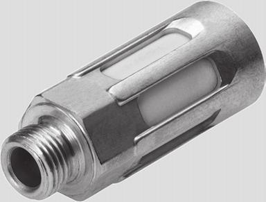
260
261
262 Plastic Tubing PUN, Standard O.D. Inch Series Overview, Ordering Data Standard O.D. tubing, suitable for QS and QB push-in fittings Wide range of diameters Wide range of colors Flexible and kink resistant Excellent hydrolysis, oil and cold resistance Conforms to NSF requirements Detailed product information Product Range Overview Type Material Outer [in] Inner [in] Color PUN Polyurethane, ester-based /8, 5/32, 3/6, /4, 5/6, 3/8, /2 /6, 3/32, /8, 5/32, 3/6, /4, 2/64 blue, yellow, green, clear, red, black, white Operating Conditions Operating medium Compressed air in accordance with ISO 8573-:200 [7: : ] Note on operating/pilot medium Operation with lubricated medium possible Temperature-dependent operating pressure [bar] [psi] 28.5 in Hg +50 Ambient temperature [ C] [ F] Hardness Shore D 52 +/-3 Fittings / Flow Controls / Silencers / Tubing Ordering Data PUN O.D. [in] I.D. [in] Color Part No. Type ) /8 /6 Blue PUN-H-/8-BL-50-CB Black PUN-H-/8-SW-50-CB 5/32 3/32 Blue PUN-H-5/32-BL-50-CB Black PUN-H-5/32-SW-50-CB 3/6 /8 Blue PUN-H-3/6-BL-50-CB Black PUN-H-3/6-SW-50-CB /4 5/32 Blue PUN-H-/4-BL-50-CB Black PUN-H-/4-SW-50-CB ) Packaging quantity is 50 meters / 50 ft PUN O.D. [in] I.D. [in] Color Part No. Type ) 5/6 3/6 Blue PUN-H-5/6-BL-50-CB Black PUN-H-5/6-SW-50-CB 3/8 /4 Blue PUN-H-3/8-BL-50-CB Black PUN-H-3/8-SW-50-CB /2 2/64 Blue PUN-H-/2-BL-50-CB Black PUN-H-/2-SW-50-CB ) Packaging quantity is 50 meters / 50 ft 6 Lead Time LT for all products on this page: D typically ships same day/next day 258 Internet: FAST Program Catalog Subject to change 204/06

263 Plastic Tubing PUN, Standard O.D. Metric Series Overview Standard O.D. tubing, suitable for QS and QB push-in fittings Wide range of diameters Wide range of colors Flexible and kink resistant Free of copper and PTFE Conforms to RoHS Detailed product information Product Range Overview Type Material Outer [mm] Inner [mm] Color PUN Polyurethane, ester-based 3, 4, 6, 8, 0, 2, 6 2., 2.6, 4.0, 5.7, 7.0, 8.0,.0 blue, yellow, green, red, silver, black Operating Conditions Operating medium Compressed air in accordance with ISO 8573-:200 [7: : ] Note on operating/pilot medium Operation with lubricated medium possible Operating medium Compressed air Vacuum Temperature-dependent operating pressure [bar] [psi] 28.5 in Hg +50 Ambient temperature [ C] [ F] Hardness Shore D 52 +/-3 Fittings / Flow Controls / Silencers / Tubing 6 204/06 Subject to change FAST Program Catalog Internet: 259
264 Plastic Tubing PUN, Standard O.D. Metric Series Ordering Data PUN O.D. [mm] I.D. [mm] Color Part No. Type ) Blue PUN-3X0,5-BL Yellow 7846 PUN-3X0,5-GE Green PUN-3X0,5-GN Red PUN-3X0,5-RT Silver PUN-3X0,5-SI Black 5966 PUN-3X0,5-SW Blue PUN-4X0,75-BL Yellow 7847 PUN-4X0,75-GE Green PUN-4X0,75-GN Red 7840 PUN-4X0,75-RT Silver PUN-4X0,75-SI Black PUN-4X0,75-SW Blue PUN-6X-BL Yellow 7848 PUN-6X-GE Green PUN-6X-GN Red 784 PUN-6X-RT Silver PUN-6X-SI Black PUN-6X-SW Blue PUN-8X,25-BL Yellow 7849 PUN-8X,25-GE Green PUN-8X,25-GN Red 7842 PUN-8X,25-RT Silver PUN-8X,25-SI Black PUN-8X,25-SW PUN O.D. [mm] I.D. [mm] Color Part No. Type ) Blue PUN-0X,5-BL Yellow PUN-0X,5-GE Green PUN-0X,5-GN Red 7843 PUN-0X,5-RT Silver PUN-0X,5-SI Black PUN-0X,5-SW Blue PUN-2X2-BL Yellow 7842 PUN-2X2-GE Green PUN-2X2-GN Red 7844 PUN-2X2-RT Silver PUN-2X2-SI Black 5967 PUN-2X2-SW Blue PUN-6X2,5-BL Yellow PUN-6X2,5-GE Green PUN-6X2,5-GN Red 7845 PUN-6X2,5-RT Silver PUN-6X2,5-SI Black PUN-6X2,5-SW ) Packaging quantity is 50 meters / 50 ft ) Packaging quantity is 50 meters / 50 ft Fittings / Flow Controls / Silencers / Tubing 6 Lead Time LT for all products on this page: D typically ships same day/next day 260 Internet: FAST Program Catalog Subject to change 204/06


265 Product Range and Company Overview A Complete Suite and Company Overview Our experienced engineers provide complete support at every stage of your development process, including: conceptualization, analysis, engineering, design, assembly, documentation, validation, and production. Custom Automation Components Complete custom engineered solutions Custom Control Cabinets Comprehensive engineering support and on-site services Complete Systems Shipment, stocking and storage services The Broadest Range of Automation Components With a comprehensive line of more than 30,000 automation components, Festo is capable of solving the most complex automation requirements. Electromechanical Electromechanical actuators, motors, controllers & drivers Pneumatics Pneumatic linear and rotary actuators, valves, and air supply PLCs and I/O Devices PLC s, operator interfaces, sensors and I/O devices Supporting Advanced Automation As No One Else Can! Festo is a leading global manufacturer of pneumatic and electromechanical systems, components and controls for industrial automation, with more than 6,000 employees in 60 national headquarters serving more than 80 countries. For more than 80 years, Festo has continuously elevated the state of manufacturing with innovations and optimized motion control solutions that deliver higher performing, more profitable automated manufacturing and processing equipment. Our dedication to the advancement of automation extends beyond technology to the education and development of current and future automation and robotics designers with simulation tools, teaching programs, and on-site services. Quality Assurance, ISO 900 and ISO 400 Certifications Festo Corporation is committed to supply all Festo products and services that will meet or exceed our customers requirements in product quality, delivery, customer service and satisfaction. To meet this commitment, we strive to ensure a consistent, integrated, and systematic approach to management that will meet or exceed the requirements of the ISO 900 standard for Quality Management and the ISO 400 standard for Environmental Management. Copyright 204, Festo Corporation. While every effort is made to ensure that all dimensions and specifications are correct, Festo cannot guarantee that publications are completely free of any error, in particular typing or printing errors. Accordingly, Festo cannot be held responsible for the same. For Liability and Warranty conditions, refer to our Terms and Conditions of Sale, available from your local Festo office. All rights reserved. No part of this publication may be reproduced, distributed, or transmitted in any form or by any means, electronic, mechanical, photocopying or otherwise, without the prior written permission of Festo. All technical data subject to change according to technical update. Printed on recycled paper at New Horizon Graphic, Inc., FSC certified as an environmental friendly printing plant.

 Fax: 877 FX FESTO ( 877 393")
266 Festo North America Festo Canada 2 Montréal 3 Québec City Headquarters Festo Inc Explorer Drive Mississauga, ON L4W 5G4 5600, Trans-Canada Pointe-Claire, QC H9R B6 2930, rue Watt#7 Québec, QC GX 4G3 4 Festo United States 5 Appleton 7 Detroit Headquarters Festo Corporation 395 Moreland Road North 922 Tower View Drive, Suite 200 Greenville, WI Hauppauge, NY Chicago 8 85 W Algonquin - Suite 340 Arlington Heights, IL West Long Lake Road Troy, MI Silicon Valley 4935 Southfront Road, Suite F Livermore, CA Festo Regional Contact Center Canadian Customers Commercial Support: Tel: 877 GO FESTO ( ) Fax: 877 FX FESTO ( ) festo.canada@ca.festo.com USA Customers Commercial Support: Tel: FESTO ( ) Fax: FESTO ( ) customer.service@us.festo.com Technical Support: Tel: 866 GO FESTO ( ) Fax: 877 FX FESTO( ) technical.support@ca.festo.com Technical Support: Tel: 866 GO FESTO ( ) Fax: FESTO( ) product.support@us.festo.com Subject to change Catalog No Addendum 07.5
FAST Program 2013 Festo Assured Shipping Time
 FAST Program 203 Festo Assured Shipping Time TM A complete line of automation components available when you need them! FAST TM Program 203 Festo Assured Shipping Time A complete line of automation components
Standard Cylinders DNC Inch Series, to ISO 15552
 Standard Cylinders DNC Inch Series, to ISO 5552 DNC Standard Cylinders meet ISO 5552 mounting, rod, bore and thread dimension specifications for easy interchangeability. Piston ¼ to 2½ Strokes of up to
Compact Cylinders ADN Inch Series, Based on ISO Overview
 Compact Cylinders ADN Inch Series, Based on ISO 2287 Overview Compact cylinders for maximum productivity in confined spaces, combining innovative technology, high performance and reduced installation space
Tandem/high-force cylinders
 Tandem/high-force cylinders Tandem/high-force cylinders Product range overview Function Version Type Piston Stroke Position sensing Piston rod With male thread A Doubleacting Tandem cylinders DNCT 32,
Standard cylinders DNCB, ISO 15552
 Standard cylinders DNCB, ISO 15552 Features At a glance Standards-based cylinders to ISO 15552 (corresponds to the withdrawn standards ISO 6431, DIN ISO 6431, VDMA 24 562, NF E 49 003.1 and UNI 10290)
Standard cylinders DNC-C180, to ISO 15552
 Key features At a glance Sensor slots on the compressed air connection side Standards-based cylinders to ISO15552 (corresponds to the withdrawn standards ISO 6431, DIN ISO 6431, VDMA24562, NFE49003.1 and
Clamping-unit cylinders, standard port pattern
 Key features At a glance Clamping units are generally used for the friction locking of longitudinally variable rods at any position. The attachment of a clamping unit to a pneumatic cylinder allows the
Round Cylinders DSNU, Double-acting Inch Series
 Round Cylinders DSNU, Double-acting Inch Series Piston 5/16 to 2-1/2 Stroke lengths up to 20 Double-acting Meets the highest requirements for running characteristics, service life and load carrying ability
Multi-position cylinders/adapter kits
 Multi-position cylinders/adapter kits Multi-position cylinders ADNM Product range overview Function Version Type Piston Max. stroke Piston rod With female thread With male thread Doubleacting ADNM Single-ended
Compact Cylinders ADN/AEN/ADNGF Inch Series, Based on ISO 21287
 Compact Cylinders ADN/AEN/ADNGF Inch Series, Based on ISO 21287 Compact cylinders for maximum productivity in confined spaces, combining innovative technology, high performance and reduced installation
Short-stroke cylinders ADVC/AEVC
 Short-stroke cylinders ADVC/AEVC q/w Worldwide: Superb: Easy: Festo core product range Covers 80% of your automation tasks Always in stock Festo quality at an attractive price Reduces procurement and storing
Standard cylinders DNC-C180, to ISO 15552
 -U- Type discontinued Available up until 2016 Standard cylinders DNC-C180, to ISO 15552 Key features At a glance Sensor slots on the compressed air connection side Standards-based cylinders to ISO15552
Semi-rotary drives DRQ
 Features 40 100 mm 16 32 mm Rotating and swivelling The linear movement of the cylinder is converted into rotational movement by a backlash-compensating gear unit. Precision is increased by backlashfree
Flat cylinders EZH/DZF/DZH
 Flat cylinders EZH/DZF/DZH Extremely flat design Protected against torsion thanks to special piston shape Compact assembly with block mounting Wide variety of mounting options 2017/10 Subject to change
Slide units SPZ, twin piston
 Key features Multi-axis and drive combinations The slide unit SPZ can be combined with different drives. An adapter kit is required for mounting between the two drives. DPZ-/SPZ axis Adapter kits www.festo.com
Linear/swivel clamp CLR
 Key features Functional description The linear/swivel clamp CLR is used for all types of clamping. Through the combination of the linear and swivel motion of the piston rod, it is possible to insert and
Standard cylinders DNG/DNGZS, ISO 15552
 Features Brief description Double-acting For contactless position sensing With adjustable end-position cushioning at both ends Robust tie rod design Standards-based cylinders to ISO15552 (corresponds to
Square profile cylinders DNC - Inch Series
 Piston 1-1/4 to 5 Standard strokes up to 20 Variable strokes up to 80 Double-acting Numerous variants Repairable Product range overview Function Design Piston Standard Stroke Available Stroke [lbf] P PPV
Round Cylinders ESNU, Single-acting Inch Series
 Round Cylinders ESNU, Single-acting Inch Series Piston 5/16Ė to 2-1/2Ė Stroke lengths up to 2Ė Single-acting, spring return Meets the highest requirements for running characteristics, service life and
Compact cylinders ADVUL
 Piston rod secured against rotation by means of guide rods and yoke plate Profile slots for proximity sensors Extensive range of accessories 2016/03 Subject to change Internet: www.festo.com/catalog/...
Standard cylinders DNCI, with measured-value transducer DADE
 Features Components for positioning and measuring using the standard cylinder DNCI Measuring with measured-value transducer DADE Positioning with end-position controller SPC11 or controller module CPX-CMAX/-CMPX
Standard cylinders DNC, ISO 15552
 Key features At a glance DIN Standards-based cylinders to ISO15552 (corresponds to the withdrawn standards ISO 6431, DIN ISO 6431, VDMA24562, NFE49003.1 and UNI 10290) The modern design and construction
Compact cylinders ADN/AEN, to ISO 21287
 Compact cylinders ADN/AEN, to ISO 21287 Compact cylinders ADN/AEN, to ISO 21287 Key features At a glance Sensor slots on three sides for flush mounting of proximity sensors Centring hole in the end cap
Feed separators HPVS
 Key features and peripherals overview At a glance 1 Corrosion-resistant thanks to stainless steel plunger 2 Optimum and precise adaption options using centring sleeves 3 Supply ports optionally on top
Swivel/linear drive units DSL-B
 Key features At a glance High repetition accuracy thanks to cushioning components with fixed stop Swivel angle can be infinitely and accurately set The mechanical gearing between the stop element and swivel
Standard cylinders DNCB, ISO 15552
 -U- Type discontinued Available up until 2012 Standard cylinders DNCB, ISO 15552 Features At a glance Standards-based cylinders to ISO 15552 (corresponds to the withdrawn standards ISO 6431, DIN ISO 6431,
Round Cylinders DSNU, Double-acting Inch Series
 Round Cylinders DSNU, Double-acting Inch Series Round Cylinders DSNU, Double-acting Inch Series Piston 5/16 to 2-1/2 Stroke lengths up to 20 Double-acting Meets the highest requirements for running characteristics,
Cylinders DSBG to ISO 15552
 Key features At a glance DIN Cylinders to ISO 15552 (corresponds to the withdrawn standards ISO 6431, DIN ISO 6431, VDMA 24562, NFE49003.1 and UNI 10290) Sturdy tie rod design Double-acting For contactless
Standard cylinders DNC, ISO 15552
 Key features At a glance DIN Standards-based cylinders to ISO15552 (corresponds to the withdrawn standards ISO 6431, DIN ISO 6431, VDMA24562, NFE49003.1 and UNI 10290) The modern design and construction
Twin cylinders DPZ/DPZJ
 Key features High force with excellent protection against torsion 100 to 1,000 N thrust at 6 bar operating pressure Load capacity (F q ) from 8 to 105 N F q max. Permissible torque load (T L ) centrally
Standard cylinders DSBC, to ISO 15552
 Key features At a glance DIN Standards-based cylinders to ISO 15552 (corresponds to the withdrawn standards ISO 6431, DIN ISO 6431, VDMA 24 562, NF E 49 003.1 and UNI 10290) Double-acting For contactless
-H- Note. Feed separators HPV Key features at a glance. Separation of workpieces in the supply process
 Key features at a glance Separation of workpieces in the supply process Previously Required at least 2 drives, 2 valves and 4 proximity sensors Extensive programming required Today One unit (1 drive, 1
Round cylinders DSNU/ESNU
 Round cylinders DSNU/ESNU Reacts quickly thanks to minimal break-away force Meets the highest requirements for running characteristics, service life and load carrying ability Extensive range of accessories
Compact cylinders ADN/AEN, to ISO 21287
 Compact cylinders ADN/AEN, to ISO 21287 q/w Worldwide: Superb: Easy: Festo core product range Covers 80% of your automation tasks Always in stock Festo quality at an attractive price Reduces procurement
Standard cylinders DSBG, to ISO 15552
 Key features At a glance DIN Cylinders to ISO 15552 (corresponds to the withdrawn standards ISO 6431, DIN ISO 6431, VDMA 24562, NFE49003.1 and UNI 10290) Sturdy tie rod design Double-acting For contactless
Flat Cylinders DZF - Inch Series Overview
 Flat Cylinders DZF - Inch Series Overview Non-rotating oval piston Piston 1/2 to 2-1/2 Standard strokes up to 12, variable strokes up to 13 Double-acting Moment capacity up to 13.3 lbf-in Male or female
Compact cylinders ADN-S, AEN-S
 Compact cylinders ADN-S, AEN-S Compact cylinders ADN-S, AEN-S Key features At a glance Without sintered bearing Free of copper Improved operating behaviour Due to precise manufacturing from a single piece
Standards-based cylinders DSBG to ISO 15552
 Standards-based cylinders DSBG to ISO 15552 Standards-based cylinders DSBG to ISO 15552 Key features At a glance DIN Standards-based cylinders to ISO 15552 (corresponds to the withdrawn standards ISO 6431,
Linear drives DGC-HD, with heavy-duty guide
 Linear drives DGC Key features At a glance New heavy-duty design for: Maximum loads and torques thanks to duo rail guide Long service life Ideal as a basic axis for linear gantries and cantilever axes
Linear drives SLM, with guided slide
 Key features Version The linear drive SLM is a combination of a slide unit and a rodless linear drive. The drive moves the slide. The transmission of movement is accomplished via a magnetic coupling. The
-V- New. Linear drives DGC Features. 2 Internet:
 Linear drives DGC Features At a glance Without external guide, for simple drive functions Compact fitting length relative to stroke Fully interchangeable with the linear drive DGP Easy assembly and installation
Linear drives DGPL Selection aid
 Linear drives DGPL Linear drives DGPL Selection aid General Compact, fitting length relative to stroke Highly adaptable thanks to wide choice of mounting and attachment options Adjustable end-position
Linear drives DGC-K. Festo core product range Covers 80% of your automation tasks
 q/w Worldwide: Superb: Easy: Festo core product range Covers 80% of your automation tasks Always in stock Festo quality at an attractive price Reduces procurement and storing complexity qready for dispatch
Hinge cylinders DW Key features
 Key features At a glance Hinge cylinder for clamping components during the welding process Easy assembly thanks to swivel bearing on the bearing cap Integrated flow control Integrated end-position cushioning
Linear drives SLG, flat design
 Features General information Piston 8, 12 and 18 Stroke lengths of 100 900 mm Two cushioning types selectable: Elastic cushioning Shock absorbers Direct mounting via centering holes Extremely flat design
3 Electromechanical drives
 Electromechanical drives 2015/11 Subject to change www.festo.com/catalogue/... 49 Electromechanical drives > Linear drives and slides Semi-rotary drives Electric handling modules Direct drives Accessories
Linear drive units DGO
 Features General information Double-acting Magnetically coupled without mechanical connections Piston chamber and slide are pressure tight Pressure tight and leak-free system Dirt and dust cannot enter
Standards-based cylinders DSBC, to ISO 15552
 q/w Worldwide: Superb: Easy: Festo core product range Covers 80% of your automation tasks Always in stock Festo quality at an attractive price Reduces procurement and storing complexity qready for dispatch
Mini guided cylinders DFC
 Product range and peripherals overview Function Version Type Piston Stroke [mm] [mm] Doubleacting DFC 4 5, 10, 15, 20 6 5, 10, 15, 20, 25, 0 10 5, 10, 15, 20, 25, 0 Piston 4 mm Piston 6, 10 mm Integrated
Round cylinders DSNU/DSNUP/DSN/ESNU/ESN
 Round cylinders DSNU/DSNUP/DSN/ESNU/ESN Round cylinders DSNU/DSNUP/DSN/ESNU/ESN Key features At a glance DSNU-8 63 DSNU-8 25 Stainless steel piston rod Good running performance and long service Piston
Semi-rotary drives DRVS
 Key features Key features at a glance Double-acting semi-rotary drive with rotary vanes Lighter than other semi-rotary drives Modern and compact design Fixed swivel angle Swivel angle can be adjusted with
Mini slides SLT/SLS/SLF
 Mini slides SLT/SLS/SLF Mini slides SLT/SLS/SLF Key features General information Double-acting drives Precise and rigid guide Versatile air connections Sensors can be integrated Highly flexible thanks
-U- Type discontinued
 Key features At a glance -V- New Sturdier Optimised end stop system Optimised intermediate position module Minimised susceptibility to wear One-way flow control valves that can be externally adjusted Integrated
-H- Note. Feed separators HPV Key features at a glance. Separation of workpieces in the supply process
 Key features at a glance Separation of workpieces in the supply process Previously Required at least 2 drives, 2 valves and 4 proximity sensors Extensive programming required Today One unit (1 drive, 1
Round cylinders DSNU/ESNU
 Round cylinders DSNU/ESNU q/w Worldwide: Superb: Easy: Festo core product range Covers 80% of your automation tasks Always in stock Festo quality at an attractive price Reduces procurement and storing
Linear drives DGPL Selection aid
 Linear drives DGPL Linear drives DGPL Selection aid General Compact, fitting length relative to stroke Highly adaptable thanks to wide choice of mounting and attachment options Adjustable end-position
Linear actuators DLP, Copac
 Key features and type codes General -N- Diameter 80... 320 mm -T- Stroke length 40... 600 mm, additional stroke lengths upon request -O- Force 2800... 48000 N Festo Copac linear valve actuators are ideally
-U- Type discontinued. -H- Note. Available up until Angle grippers HGWC Key features
 Key features At a glance General information The compact and cost-optimised angle gripper consists of a two-part mirrorsymmetrical housing made of die-cast zinc. The force generated by the linear motion
Flat Cylinders DZH - Inch Series Overview
 Flat Cylinders DZH - Inch Series Overview Non-rotating oval piston Piston 5/8 to 2-1/2 Strokes up to 40 Double-acting Moment capacity up to 2.2 lbf-in Extensive range of accessories Versatile mounting
Linear actuators DFPI
 Linear actuators DFPI Linear actuators DFPI Key features General information Linear actuator for actuating process valves such as gate valves and shut-off valves in process automation systems Linear actuator
Cartridge cylinders EGZ
 Peripherals overview and type codes 7 Installation without mounting attachments Minimal installation space required 4 3 2 1 Mounting attachments and accessories Description 1 Swivel mounting WBN 2 Flange
Mini slides SLT/SLS/SLF
 Mini slides SLT/SLS/SLF Mini slides SLT/SLS/SLF Key features General information Double-acting drives Precise and rigid guide Versatile air connections Sensors can be integrated Highly flexible thanks
Electric cylinders EPCO, with spindle drive
 q/w Worldwide: Superb: Easy: Festo core product range Covers 80% of your automation tasks Always in stock Festo quality at an attractive price Reduces procurement and storing complexity qready for dispatch
Standard cylinders DSBF-C, to ISO 15552, Clean Design
 Key features At a glance DIN Standards-based cylinders to ISO 15552 (corresponds to the withdrawn standards ISO 6431, DIN ISO 6431, VDMA 24562, NF E 49 003.1 and UNI 10290) The standard cylinder is used
Round cylinders DSEU/ESEU
 Features DSEU-50/63 DSEU-8 40 DSEU- -MQ DSEU- -MA Brief description Compact design Greater flexibility thanks to various end caps Practical mounting options With flexible cushioning rings in the end-positions
Proximity sensors SMT/SME-10, for C-slot
 Proximity sensors SMT/SME-10, for C-slot Proximity sensors SMT/SME Product range overview Design Type of mounting Measuring principle Type Operating voltage range For C-slot Standard Insertable in slot
Handling modules HSP
 Handling modules HSP Handling modules HSP Key features at a glance Field of application Special features The handling module is a new generation of function modules for the automatic transfer, feed and
Compact cylinders CDC, ISO 21287, Clean Design
 Key features Design Easy to clean Easy to assemble Versatile With the CDC (Clean Design Compact) cylinder series, the ADN modular system has been expanded to include an easy to clean compact cylinder variant
Linear drives DGC Key features
 Linear drives DGC Linear drives DGC Key features General information Compact fitting length relative to stroke Loads and devices can be directly mounted on the slide Three types of cushioning available:
Hinge cylinders DFAW
 Key features At a glance Hinge cylinder for clamping components during the welding process Sintered bronze bushes as lowfriction bearing material on rod clevis and swivel bearing Clamping unit: With piston
-H- Note. Angle grippers HGWC Key features. 2 Internet:
 Key features At a glance General information The compact and cost-optimised angle gripper consists of a two-part mirrorsymmetrical housing made of die-cast zinc. The force generated by the linear motion
Standard cylinders DDPC, with measured-value transducer DADE
 Features Components for positioning and measuring using the standard cylinder DDPC Measuring with measured-value transducer DADE Positioning with end-position controller SPC11 or controller module CPX-CMAX/-CMPX
Swivel modules DSM/DSM-B
 Swivel modules DSM/DSM-B Swivel modules DSM/DSM-B Key features At a glance Double-acting swivel module with rotary vanes The swivel angle is infinitely adjustable over the entire swivel range High precision
Guided drives DFM/DFM-B
 Guided drives DFM/DFM-B q/w Worldwide: Superb: Easy: Festo core product range Covers 80% of your automation tasks Always in stock Festo quality at an attractive price Reduces procurement and storing complexity
Guided drives DFM/DFM-B
 Guided drives DFM/DFM-B q/w Worldwide: Superb: Easy: Festo core product range Covers 80% of your automation tasks Always in stock Festo quality at an attractive price Reduces procurement and storing complexity
-U- Type discontinued. -H- Note. Available up until Angle grippers HGW Key features. 2 Internet:
 Key features At a glance Double-acting piston drive Self-centring Variable gripping action: External/internal gripping Versatility thanks to externally adaptable gripper fingers Wide range of options for
Twin-piston semi-rotary drives DRRD
 Twin-piston semi-rotary drives DRRD Twin-piston semi-rotary drives DRRD Key features At a glance Rack and pinion principle Very high accuracy in the end positions Very high bearing load capacity Very good
Linear drives DGC. Festo core product range Covers 80% of your automation tasks
 Linear drives DGC q/w Worldwide: Superb: Easy: Festo core product range Covers 80% of your automation tasks Always in stock Festo quality at an attractive price Reduces procurement and storing complexity
Radial grippers DHRS
 Key features At a glance General information Flexible range of applications Lateral gripper jaw support for high torque loads Self-centring Gripper jaw centring options Max. repetition accuracy Gripping
Mini slides SLTE, electric
 Key features Range of applications Special features The electric mini slide SLTE is ideal for use in automation applications where controlled end-position cushioning (gentle stopping), constant travel
Slim, Flat, Elliptical Piston DZH Cylinders Provide Non-rotating Linear Actuation in up to 50% Less Space
 Non-Rotating Elliptical Piston Cylinders, Type DZH Features and Benefits Slim, Flat, Elliptical Piston DZH Cylinders Provide Non-rotating Linear Actuation in up to 50% Less Space Patented elliptical piston/seal
Parallel grippers HGP, with protective dust cap
 Key features At a glance Double-acting piston drive With protective dust cap for use in dusty environments (protection class IP54) Self-centring Variable gripping action: External/internal gripping High
Stopper cylinders DFSP
 Key features At a glance Versions: Trunnion Trunnion with female thread Roller Single-acting, pulling Double-acting with spring, pulling Double-acting without spring With or without protection against
Parallel grippers HGPL-B, heavy-duty with long stroke
 Key features At a glance Sturdy The T-slot in combination with the long guide length allows for high forces and torques Space-saving Two parallel and opposing pistons move the gripper jaws directly and
Standard cylinders DSBF-C, to ISO 15552, Clean Design
 Key features At a glance Design Easy to clean Easy to mount Flexible DIN Standards-based cylinders to ISO 15552 (corresponds to the withdrawn standards ISO 6431, DIN ISO 6431, VDMA 24 562, NF E 49 003.1
Radial grippers DHRS
 Key features At a glance General information Flexible range of applications Lateral gripper jaw support for high torque loads Self-centring Gripper jaw centring options Max. repetition accuracy Gripping
Linear drives DGPL, with external displacement encoder
 Linear drives DGPL, with external displacement encoder Cylinders with displacement encoder Product range overview Function Type Description Drives Rodless DDLI Without guide With contactless measuring
Stopper cylinders DFST
 Key features At a glance Gentle stopping without impact vibration or noise Single-acting or double-acting Powerful shock absorber for high energy absorption Wide range of applications thanks to adjustable
Parallel grippers HGPC
 Key features At a glance General The compact and low-cost parallel gripper consists of a two-part symmetrical housing. The piston moves traverse to the half-shell casing in an optimum housing design that
Guided drives DGRF-C, Clean Design
 Features and Product range overview At a glance The guided drive is used wherever hygiene, ease of cleaning and resistance are important, predominantly in dry and splash zones in the food and packaging
On-off Valves MS-EE, Inch Series Overview
 On-off Valves MS-EE, Inch Series Overview Electrically actuated on-off valve for pressurising and exhausting pneumatic systems Choice of three voltage ranges 2 sizes: MS4 grid dimension.6 in, MS6 grid
On-off Valves MS-EM, Inch Series Overview
 On-off Valves M-EM, Inch eries Overview Manually operated on-off valve for pressurising and exhausting pneumatic systems 2 sizes: M4 grid dimension.6 in, M6 grid dimension 2.4 in Detailed product information
Spindle axes DGE Key features
 Spindle axes DGE Spindle axes DGE Key features At a glance Precision, rigid guide Highly adaptable, thanks to wide choice of mounting and attachment options Wide range of options for attaching drive units
Index. -V- New. -N- Diameters. -T- Stroke lengths. Pneumatic linear drive units DGP/DGPL Key features at a glance Festo AG & Co.
 Index Key features at a glance 3 4 7 6 2 1 5 DGP with driver DGPL with slide -V- New Protected version GA with shock absorber kit E Version free of copper, Teflon and silicone CT Load inverter AK -N- Diameters
Parallel grippers DHPS
 Key features At a glance General information Flexible range of applications Resilient and precise T slot guide of the gripper jaws Oval piston for high gripping forces High gripping forces with compact
Electric cylinders EPCO, with spindle drive
 Key features At a glance General Properties Range of applications The electric cylinder EPCO is a mechanical linear drive with piston rod and permanently attached motor. The driving component consists
Twin-piston semi-rotary drives DRRD
 Twin-piston semi-rotary drives DRRD q/w Worldwide: Superb: Easy: Festo core product range Covers 80% of your automation tasks Always in stock Festo quality at an attractive price Reduces procurement and
Electric cylinders ESBF, with spindle drive
 q/w Worldwide: Superb: Easy: Festo core product range Covers 80% of your automation tasks Always in stock Festo quality at an attractive price Reduces procurement and storing complexity qready for dispatch
Passive guide axes DGC-FA, without drive
 Key features At a glance Driveless linear guide units with guide and freely movable slide The passive guide axis is designed to support force and torque capacity in multi-axis applications Higher torsional
Solenoid valves VUVS/valve manifold VTUS, NPT
 Solenoid valves VUVS/valve manifold VTUS, NPT Solenoid valves VUVS/valve manifold VTUS, NPT Key features Innovative Versatile Reliable Easy to install A reliable, heavy-duty valve with a long service life