Installation Instructions
|
|
|
- Florence Riley
- 5 years ago
- Views:
Transcription


1 Installation Instructions 2.0T FSI Intake Manifold: Featuring better flow, higher boost capacity, 40% larger plenum volume, and integrated flapper delete; this product will take your 2.0L VW TSI and FSI to the next level. A direct replacement for your OEM plastic intake manifold. Once installed, the finished result should look like this before installation of the engine cover: PLEASE NOTE: Disconnect battery negative terminal before installation. Cool down the engine before installation. Please note placement of parts and bolts during removal.


2 INSTRUCTIONS: 1) Remove engine cover including duct to rad support. a. Remove clamp and unplug connector b. Remove duct from radiator support

 Remove PVC Hose CAUTION")
3 2) Disconnect quick connect fuel lines near coolant reservoir. 3) Remove PVC Hose CAUTION FUEL UNDER PRESSURE

 Remove both vacuum hoses from")
4 4) Remove bolt holding coolant pipe to intake manifold and move coolant pipe aside. 5) Remove both vacuum hoses from crankcase breather and valve cover.

 Remove nut and stud holding oil dipstick tube")
5 6) Unplug fuel pressure sender connector and disconnect fuel lines underneath high pressure fuel pump. 7) Remove nut and stud holding oil dipstick tube under intake manifold and remove dip-stick and tube.

 Disconnect hose on left side of N249 and fold out of way.")
6 8) Remove engine under cover (belly pan). For more access, remove 4 screws for electric fan shroud and pull fan shroud out from underneath. 9) Disconnect hose on left side of N249 and fold out of way. 10) Remove torx screw holding N249 recirculation valve bracket.


7 11) Remove 2 screws from charge air pipe and remove out through bottom of car. 12) unplug connector on throttle body 13) Remove 4 bolts holding throttle body to intake manifold. Remove throttle body. 14) Remove upper bolt from intake manifold brace.

 Remove fuel pressure sensor connector off of fuel rail.")
8 15) Remove lower bolt from intake manifold brace and remove brace. Not to be re-installed. 16) Remove nuts/bolts holding intake manifold to cylinder head. 17) Remove fuel pressure sensor connector off of fuel rail. 18) Carefully pull intake manifold and fuel rail off cylinder head. 19) Remove air diverter plates from cylinder heads.


9 20) File down plastic guide pins until flush, then reinstall. 21) Install the 3 supplied extended studs to tope center holes. NOTE: Shorter thread on stud is on head side 22) Clean gasket surface of the head.


10 23) Remove breather pipe and fuel hard lines from intake manifold and fuel rail. 24) Make sure all connections are loosened and ensure the fuel rail is free from intake manifold, connectors, and lines. Remove fuel rail from intake manifold.


11 25) Remove flapper motor and retain rod on original manifold. 26) Re-fit parts to HPA Intake Manifold with supplied bolts and washers and torque to 10 Nm. Fuel rail is no longer bolted directly to the intake manifold. Please be patient in fitting the fuel rail to the manifold as tolerances may be tight.


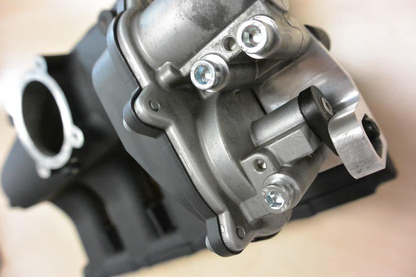
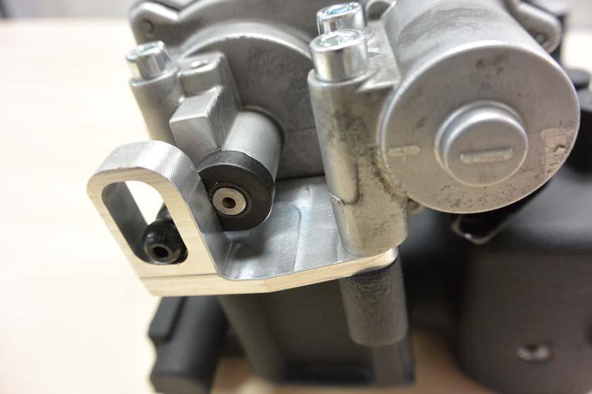
12 27) Install provided flapper motor stopper and flapper motor with supplied and M6 bolts according to the following pictures.
13


14 28) Install provided breather fittings with crush washers and threaded brass fittings/plugs with supplied thread sealant to HPA Intake Manifold.

15 29) Remove G410 low pressure switch and Schrader valve port and install in opposite positions. Original Positioning


16 Final Positioning 30) Insert OEM outer intake manifold to cylinder head bolts to loosely hold the fuel rail brackets to the intake manifold in preparation for mounting. Apply a 2-3mm bead of silicone sealant around each intake port. Make sure the mating surface of the intake manifold is cleaned with brake cleaner prior to application. Silicone Sealant
 Apply 2-3 mm bead of silicone sealant to cleaned throttle body surface and install throttle body to intake manifold with supplied bolts and washers. Torque to 10 Nm.")
17 31) Apply a light film of synthetic engine oil to injector o-rings. Slide HPA Intake Manifold onto installed studs on the cylinder head and tighten OEM bolts and supplied nuts to 10 Nm. 32) Apply 2-3 mm bead of silicone sealant to cleaned throttle body surface and install throttle body to intake manifold with supplied bolts and washers. Torque to 10 Nm. Silicone Sealant 33) Reconnect previously removed fuel lines, PCV pipes, breather pipes. 34) Install oil dip stick tube with supplied bolt and washers and torque to 10 Nm. 35) Install charge air pipe in reverse steps of removal. 36) Install radiator fan shroud if previously removed. 37) Install engine under cover (belly pan). 38) Remove engine cover mounting studs and add supplied hardware to the threaded end (2 x washers, 1 x nut). Repeat for all 4 mounting studs. Re-install studs after spacing is complete.

 Connect battery ground and start engine and check installation for leaks. a. Recommended to use a professional smoke test machine for best testing results.")
18 39) Trim notch in engine cover to provide clearance for oil dipstick and install engine cover. Add 2 inches of wire to intake air temperature sensor wiring with supplied butt connectors. After crimping connectors, please heat with heat gun or lighter to seal connections. 40) Connect battery ground and start engine and check installation for leaks. a. Recommended to use a professional smoke test machine for best testing results.
19 NOTES:
Installation Instructions
 Installation Instructions 2.0T TSI Intake Manifold: Featuring better flow, higher boost capacity, 40% larger plenum volume, and integrated flapper delete; this product will take your 2.0L VW TSI to the
INSTALLATION INSTRUCTIONS CATCH CAN KIT
 INSTALLATION INSTRUCTIONS CATCH CAN KIT FORD FOCUS Document: 19-0150 Support: info@radiumauto.com STEPS 1 TO 19 COVER THE PCV SIDE CATCH CAN KIT (P/N: 20-0315) STEPS 20-32 COVER THE CRANKCASE CATCH CAN
INSTALLATION INSTRUCTIONS CATCH CAN KIT
 INSTALLATION INSTRUCTIONS CATCH CAN KIT FORD FOCUS Document: 19-0150 Support: info@radiumauto.com STEPS 1-19 COVER THE PCV SIDE CATCH CAN KIT (P/N: 20-0315) STEPS 20-32 COVER THE CRANKCASE CATCH CAN KIT
 Page 1 of 14 Oil Pan Removal & Installation 4.2L Engine 4WD Vehicles To Remove: 1. Before servicing the vehicle refer to the precautions at the beginning of this section. 2. Raise and support the vehicle.
INSTALLATION INSTRUCTIONS CATCH CAN KIT
 INSTALLATION INSTRUCTIONS CATCH CAN KIT FORD FOCUS Document: 19-0150 Support: info@radiumauto.com STEPS 1 TO 19 COVER THE PCV CATCH CAN KIT (P/N: 20-0315) STEPS 20-32 COVER THE CRANKCASE CATCH CAN KIT
REMOVAL & INSTALLATION
 REMOVAL & INSTALLATION NOTE: For reassembly reference, label all electrical connectors, vacuum hoses and fuel lines before removal. Also place mating marks on engine hood and other major assemblies before
1991 Volkswagen Vanagon Syncro
 corner of radiator. See Fig. 1. Fig. 1: Bleeding Cooling System 2. Open bleeder valve in engine compartment (turn counterclockwise). See Fig. 1. Fill expansion tank until full. Start and run engine at
APR, LLC
 + 1. 3 3 4. 5 0 2. 5 1 8 1 4 8 0 0 U S H W Y 2 8 0 W e s t, O p e l i k a, A l a b a m a 3 6 8 0 1 4 8 0 0 U S H W Y 2 8 0 W e s t, O p e l i k a, A l a b a m a 3 6 8 0 1 + 1. 3 3 4. 5 0 2. 5 1 8 1 NOTES:
IAG Street Series Air / Oil Separator (AOS) For 2017 WRX
 For 2017 WRX") P IAG Street Series Air / Oil Separator (AOS) For 2017 WRX Part# IAG-ENG-7152 Tools Required: Ratchet, torque wrench, extensions, needle nose pliers, hose cutter, snips/scissors, flathead screwdriver,
P IAG Street Series Air / Oil Separator (AOS) For 2017 WRX Part# IAG-ENG-7152 Tools Required: Ratchet, torque wrench, extensions, needle nose pliers, hose cutter, snips/scissors, flathead screwdriver,
4 December 2017 PN# , , Dodge 6.7L Rumble B SXE (I-00400) 1. BD Rumble B SXE. D o d g e 6. 7 L H P C R Installation Instructions
 1. BD Rumble B SXE. D o d g e 6. 7 L H P C R Installation Instructions") 4 December 2017 PN#1045705, 1045706, 1045708 Dodge 6.7L Rumble B SXE (I-00400) 1 DOWNLOAD ENHANCED INSTALL MANUALS AT dieselperformance.com BD Rumble B SXE D o d g e 6. 7 L H P C R Installation Instructions
4 December 2017 PN#1045705, 1045706, 1045708 Dodge 6.7L Rumble B SXE (I-00400) 1 DOWNLOAD ENHANCED INSTALL MANUALS AT dieselperformance.com BD Rumble B SXE D o d g e 6. 7 L H P C R Installation Instructions
 Page 1 of 6 Section 03-01C: Engine, 7.5L MFI 1996 Bronco/F-Series Workshop Manual IN-VEHICLE SERVICE Procedure revision date: 06/19/2000 Cylinder Heads Removal SPECIAL SERVICE TOOL(S) REQUIRED Description
1999 E-Series Workshop Manual
 http://www.fordservicecontent.com/pubs/content/~wsxm/~mus~len/21/sxm31c16.h... Page 1 of 3 SECTION 303-01C: Engine 6.8L 1999 E-Series Workshop Manual IN-VEHICLE REPAIR Procedure revision date: 06/30/1998
2001 Ford Windstar ENGINES 3.8L V6 - VIN 4 - Windstar
 COWL TOP VENT PANEL 1. Remove windshield wiper pivot arms. Remove cowl top vent panel retaining screws. Release cowl top vent panel retaining clips. Remove windshield wiper fluid hose. Remove cowl top
IAG Street Series Air / Oil Separator (AOS) For WRX
 For WRX") P IAG Street Series Air / Oil Separator (AOS) For 2015-16 WRX Part# IAG-ENG-7152 Tools Required: Ratchet, torque wrench, extensions, needle nose pliers, hose cutter, snips/scissors, flat head screw driver,
P IAG Street Series Air / Oil Separator (AOS) For 2015-16 WRX Part# IAG-ENG-7152 Tools Required: Ratchet, torque wrench, extensions, needle nose pliers, hose cutter, snips/scissors, flat head screw driver,
2003 Taurus/Sable Workshop Manual
 Page 1 of 24 SECTION 303-01A: Engine 3.0L (2V) ASSEMBLY 2003 Taurus/Sable Workshop Manual Engine Special Tool(s) Piston Ring Compressor 303- D032 (D81L-6002-C) Camshaft Bearing Set 303-017 (T65L-6250-A)
1996 Aerostar/Ranger/Explorer
 Page 1 of 11 Section 03-01B: Engine, 3.0L V-6 IN-VEHICLE SERVICE 1996 Aerostar and Ranger Vehicles Workshop Manual Water Pump SPECIAL SERVICE TOOL(S) REQUIRED Description Tool Number Fan Clutch Holding
2000 Econoline Workshop Manual. 3. Install the upper intake manifold. 2. NOTE: Tighten the bolts in two stages.
 2. NOTE: Tighten the bolts in two stages. Tighten the bolts in the sequence shown. Stage 1: Tighten to 2 Nm (18 lb-in). Stage 2: Tighten to 10 Nm (89 lb-in). 3. Install the upper intake manifold. Position
Dodge 6.7L
 22 March 2016 2007-2010 6.7L Dodge Cummins (I-00014) 1 A Tuner capable of eliminating DTC codes, must be used with this kit. EXHAUST GAS BLOCKER KIT 2007-2016 Dodge 6.7L Part #: 1090011 Part #: 1090012
IAG Competition Series Air / Oil Separator (AOS) For WRX
 For WRX") P IAG Competition Series Air / Oil Separator (AOS) For 2015-16 WRX Part# IAG-ENG-7252 Tools Required: Ratchet, torque wrench, extensions, needle nose pliers, hose cutter, snips/scissors, flat head screw
P IAG Competition Series Air / Oil Separator (AOS) For 2015-16 WRX Part# IAG-ENG-7252 Tools Required: Ratchet, torque wrench, extensions, needle nose pliers, hose cutter, snips/scissors, flat head screw
1988 Ford F-350 PICKUP
 1988 Ford F-350 PICKUP Submodel: Engine Type: V8 Liters: 7.5 Fuel Delivery: FI Fuel: GAS 1987 93 4.9L Engine The intake and exhaust manifolds on these engines are known as combination manifolds and are
05-08 GT. Hellion Power Systems Mustang Kit Instructions
 Hellion Power Systems 05-08 Mustang Kit Instructions 1. Disconnect Battery 2. Drain Radiator, keep fluid for re-installation. 3. Remove air box and inlethoses. 6. Next, underneath, punch oil pan for turbo
FREE $15 Gift Card for every $100 spent on Ship To Home orders. Find Out How
 1 of 29 10/12/2011 5:05 PM FREE $15 Gift Card for every $100 spent on Ship To Home orders. Find Out How Ford Ranger/Explorer/Mountaineer 1991-1999 Intake Manifold REMOVAL & INSTALLATION Print The engines
Disconnect the breather tube from the air cleaner outlet duct.
 Disconnect the breather tube from the air cleaner outlet duct. Disconnect the IAT sensor harness connector. Remove the air cleaner outlet duct retaining wingnut. Separate the air cleaner outlet duct from
ADJUSTMENTS Mazda MX-3. Fig. 1: Identifying Engine Code & Number Courtesy of MAZDA MOTORS CORP. VALVE CLEARANCE ADJUSTMENT
 Fig. 1: Identifying Engine Code & Number Courtesy of MAZDA MOTORS CORP. ADJUSTMENTS VALVE CLEARANCE ADJUSTMENT 1. No valve clearance adjustment is required, as hydraulic valve lash adjusters are used.
SLP Camaro ZL1 STAGE 3 (650 HP)
") SLP - 2012 Camaro ZL1 STAGE 3 (650 HP) PART #26002 PACKING LIST Before installation, use this check list to make sure all necessary parts have been included. ITEM QTY CHECK PART NUMBER DESCRIPTION 1. 1
SLP - 2012 Camaro ZL1 STAGE 3 (650 HP) PART #26002 PACKING LIST Before installation, use this check list to make sure all necessary parts have been included. ITEM QTY CHECK PART NUMBER DESCRIPTION 1. 1
Procharger Stage II Intercooled Supercharger System (11-14 GT)
") Procharger Stage II Intercooled Supercharger System (11-14 GT) Installation Time: Approximately one day. Installed on 2012 Mustang GT 5.0/Manual Required Tools 3/8 Socket Set (Standard and Metric) 1/2
Procharger Stage II Intercooled Supercharger System (11-14 GT) Installation Time: Approximately one day. Installed on 2012 Mustang GT 5.0/Manual Required Tools 3/8 Socket Set (Standard and Metric) 1/2
#TL T EA888 GEN 3 FUELING SYSTEM/ INSTALLATION INSTRUCTIONS
 #TL100069 2.0T EA888 GEN 3 FUELING SYSTEM/ INSTALLATION INSTRUCTIONS Notes: These instructions were written for a North American specification MkVII GTI. Other models, like the Golf R, are similar. When
1 of 12 10/5/2015 8:11 AM
 1 of 12 10/5/2015 8:11 AM REMOVAL 1. Perform the fuel pressure release procedure See: Fuel Pressure Release > Procedures > Fuel System Pressure Release Procedure. 2. Recover the refrigerant from the refrigerant
INSTALLATION INSTRUCTIONS AIR/OIL SEPARATOR KIT
 INSTALLATION INSTRUCTIONS AIR/OIL SEPARATOR KIT 2015+ SUBARU WRX (LHD ONLY) Document: 19-0136 Support: info@radiumauto.com This document covers the installation of the Radium brake master cylinder brace
Installation Manual v1.0: Twin CP3 Fuel Injection Kit Dodge 5.9L
 Installation Manual v1.0: Twin CP3 Fuel Injection Kit 2004.5-2007 Dodge 5.9L Figure 1 - Full Kit Photo 25 Figure 2 - Hardware Kit Please read all instructions before installation. This kit is not emissions
BD 6.7L Super B Special Turbo Kit For L Dodge -- I n s t a l l a t i o n I n s t r u c t i o n s -- PN#
 26 September 2012 1045140 6.7L Super B Special Turbo Installation 1 BD 6.7L Super B Special Turbo Kit For 2007.5-2012 6.7L Dodge -- I n s t a l l a t i o n I n s t r u c t i o n s -- PN# 1045140 PLEASE
NOTE: Do not disassemble upper intake manifold from lower intake manifold unless replacement of one of the components is necessary.
 Fig. 2: Lower Intake Manifold Bolt Tightening Sequence INTAKE MANIFOLD (UPPER) NOTE: Do not disassemble upper intake manifold from lower intake manifold unless replacement of one of the components is necessary.
Step 6: Remove and save the MAP sensor for later use. Step 7: Remove the passenger side intercooler pipe and the EGR intake manifold.
 LBZ Twin kit Install Step 1: Disconnect both batteries. Step 2: Drain coolant and oil also remove passenger side inner fender. Step 3: Remove intake box and piping. (Remove and save the MAF sensor in the
2015 Corvette Supercharger System Instructions
 2015 Corvette Supercharger System Instructions These instructions are meant to serve as a guide to the installation of the ECS 2015 Corvette Supercharging system. Please be sure to use all safety equipment
Exhaust Gas Recirculation Valve, Replace J S file://c:\program Files\cosids\DATA\TMP\ rtf.html. Remove
 1 Page 1 of 20 Exhaust Gas Recirculation Valve, Replace J982500 Remove 1. Disconnect battery negative lead 2. Disconnect hose (1) from oil filler on air cleaner assembly, then move to one side Release
4. Remove (4) 10mm and (1) 7mm bolt that holds fascia at front corners, on each side
 10mm and (1) 7mm bolt that holds fascia at front corners, on each side") 2010 Camaro LS3 1. Disconnect battery ground 2. Remove front wheels 3. Remove (5) push pins and (5) #20 torx screws on inner front wheel well liners and remove liners on each side 4. Remove (4) 10mm and
2010 Camaro LS3 1. Disconnect battery ground 2. Remove front wheels 3. Remove (5) push pins and (5) #20 torx screws on inner front wheel well liners and remove liners on each side 4. Remove (4) 10mm and
Ford 6.0L. Part #: Part #: BD GASKET PART# will be needed for this installation.
 1 BD EGR COOLER 2003-2007 Ford 6.0L Part #: 1090201 Part #: 1090202 PLEASE READ ALL INSTRUCTIONS BEFORE INSTALLATION BD GASKET PART# 1090002 will be needed for this installation. 2 K I T C O N T E N T
2000 Chrysler SEBRING
 2000 Chrysler SEBRING Submodel: JX Engine Type: V6 Liters: 2.5 Fuel Delivery: FI Fuel: GAS 2.0L SOHC and 2.4L DOHC Engines The intake manifold for the 2.0L SOHC engine is a long branch design made of a
BD TrackMaster S D o d g e H P C R Installation Instructions
 7 July 2016 PN#1045701, 1045702, 1045704 Dodge 6.7L TMS400 (I-00361) 1 BD TrackMaster S400 2008-2012 D o d g e H P C R Installation Instructions 1045701 2008-2009 Dodge 6.7L TMS400 1045702 2010-2012 Dodge
Keeping You Cool Under Pressure
 Installation Instruction for 92-93 GM 6.5L Turbo Diesel Series 3500-4 Wheel Drive Pickup and Series 1500, 2500, 3500 4 Wheel Drive Suburban Intercooler System (Part No. 2-436) TOOLS REQUIRED: 1.) Normal
Installation Instructions
 Installation Instructions Transverse K04 Tools Required Jack and jack stands Drain pan for coolant and oil 3" and 6" extensions Channel locks 7mm, 8mm, 10mm, 11mm, 12mm, 13mm, and 16mm sockets Oxygen sensor
1997 Volvo 850 GLT. Fig. 2: Removing Drive Shaft, Engine Mount Bolt & Torque Arm (5-Cylinder) Courtesy of VOLVO CARS OF NORTH AMERICA.
 Courtesy of VOLVO CARS OF NORTH AMERICA.") Fig. 2: Removing Drive Shaft, Engine Mount Bolt & Torque Arm (5-Cylinder) 4. Remove front exhaust pipe nuts and springs. Remove front exhaust pipe bolts. Disconnect speedometer. Remove engine mounting
Fig. 2: Removing Drive Shaft, Engine Mount Bolt & Torque Arm (5-Cylinder) 4. Remove front exhaust pipe nuts and springs. Remove front exhaust pipe bolts. Disconnect speedometer. Remove engine mounting
SHORT RAM AIR INTAKE SYSTEM. Installation Instructions for: Part Number Nissan 350Z
 SHORT RAM AIR INTAKE SYSTEM Installation Instructions for: Part Number 22-547 2003-2006 Nissan 350Z ADVANCED ENGINE MANAGEMENT INC. 2205 126 TH Street, Unit A Hawthorne, CA. 90250 Phone: (310) 484-2322
Ford Racing Performance Improvement Intake Manifold (96-04 GT) Time Necessary: Approximately 4 hours
 Time Necessary: Approximately 4 hours") Ford Racing Performance Improvement Intake Manifold (96-04 GT) Time Necessary: Approximately 4 hours Tools Required: Ratchet and socket set Torque wrench Large adjustable wrench Needle nose pliers A dozen
Ford Racing Performance Improvement Intake Manifold (96-04 GT) Time Necessary: Approximately 4 hours Tools Required: Ratchet and socket set Torque wrench Large adjustable wrench Needle nose pliers A dozen
Zoom and Print Options
 Vehicle» Engine, Cooling and Exhaust» Engine» Service and Repair» Removal and Replacement» Engine Replacement Engine Replacement ^ Tools Required - J 38185 Hose Clamp Pliers Removal Procedure 1. Remove
Zoom and Print Options
 Vehicle» Engine, Cooling and Exhaust» Engine» Cylinder Head Assembly» Valve Cover» Service and Repair» Procedures» RH Valve Cover RH Removal 1. Disconnect the battery ground cable. 2. Remove the air cleaner
2016 Camaro Header Installation
 TEXAS-SPEED.COM 2016 Camaro Header Installation Tools 8mm Socket 11mm Socket 5/8 Spark Plug Socket T15, T35 Torx Bit 5mm Allen Bit 10mm Socket and Wrench 11mm Socket and Wrench 3/8 Drive Ratchet, Torque
Huron Speed Products Twin Turbo Install Gen 2 CTS-V (09-15)
") Huron Speed Products Twin Turbo Install Gen 2 CTS-V (09-15) 1 2 Remove two bolts in trunk cover with 8mm socket. Pull up on cover to remove. Unscrew net tie down on side cover where battery is located
Huron Speed Products Twin Turbo Install Gen 2 CTS-V (09-15) 1 2 Remove two bolts in trunk cover with 8mm socket. Pull up on cover to remove. Unscrew net tie down on side cover where battery is located
TABLE OF CONTENTS PARTS LIST
 TROUBLESHOOTING: Note: You will have a check engine light and/or other problems unless using this product with a compatible ECM calibration. Contact your tuning supplier to learn whether or not aftermarket
Crawford Performance Top Mount Air/Oil Separator Install Instructions Version 1.12
 Crawford Performance Top Mount Air/Oil Separator Install Instructions Version 1.12 Parts List Part Number Quantity Description Sent Received S0774 1 TMIC Air/Oil Separator F0365 1 Crank Case Breather Connector
 Special Tools Needed: DrVanos.com Stage I Installation Instructions Camshaft locking tool TDC Crank pin Sprocket turning tool Tool rental is available with the purchase of a vanos kit *See website for
Part number SP Honda Element 2.4L, 4 cyl.
 Part number SP1727 07-08 Honda Element 2.4L, 4 cyl. 1-2 piece cold air intake 1-3 Injen filter (#1017) 1-2.75 straight hose (#3043) 1-3 straight hose (#3044) 1-12 8mm vacuum hose (#3091) 2- Power Bands.312.040
IAG Street Series Air / Oil Separator (AOS) For WRX
 For WRX") IAG Street Series Air / Oil Separator (AOS) For 2008-14 WRX Part# IAG-ENG-7100 Tools Required: Ratchet, extensions, needle nose pliers, hose cutter, snips/scissors, flat head screw driver, hose clamping
IAG Street Series Air / Oil Separator (AOS) For 2008-14 WRX Part# IAG-ENG-7100 Tools Required: Ratchet, extensions, needle nose pliers, hose cutter, snips/scissors, flat head screw driver, hose clamping
2002 Explorer Sport/Sport Trac Workshop Manual
 Page 1 of 17 SECTION 303-01: Engine 4.0L Single Overhead Camshaft (SOHC) IN-VEHICLE REPAIR Procedure revision date: 07/13/2005 Cylinder Head Special Tool(s) Spark Plug Wire Remover 303-106 (T74P-6666-A)
Crawford Performance Top Mount Air/Oil Separator Version 2 (S0714-1)
") Crawford Performance Top Mount Air/Oil Separator 02-07 Version 2 (S0714-1) Parts List Part Number Quantity Description Sent Received S0707-1 1 TMIC Air/Oil Separator V2 F0365 1 Crank Case Breather Connector
Crawford Performance Top Mount Air/Oil Separator 02-07 Version 2 (S0714-1) Parts List Part Number Quantity Description Sent Received S0707-1 1 TMIC Air/Oil Separator V2 F0365 1 Crank Case Breather Connector
Equipped with AEM Dryflow Filter No Oil Required! INSTALLATION INSTRUCTIONS PART NUMBER DS (GUN METAL GRAY FINISH)
") Equipped with AEM Dryflow Filter No Oil Required! INSTALLATION INSTRUCTIONS PART NUMBER 21-823DS (GUN METAL GRAY FINISH) 1 ITEM NO. PART NUMBER DESCRIPTION QTY. 1 21-202DOSK AIR FILTER; OFFSET 2.75" X
Equipped with AEM Dryflow Filter No Oil Required! INSTALLATION INSTRUCTIONS PART NUMBER 21-823DS (GUN METAL GRAY FINISH) 1 ITEM NO. PART NUMBER DESCRIPTION QTY. 1 21-202DOSK AIR FILTER; OFFSET 2.75" X
Cylinder head/gasket, replacing
 1(16) Cylinder head/gasket, replacing Special tools: 951 2666, 951 2767, 999 5450, 999 5452, 999 5454, 999 5670, 999 5718, 999 5719, 999 5750, 999 5972 Removing the cylinder head gasket Note! As the illustrations
DrVanos.com Stage II Installation Instructions. Tool rental is available with the purchase of a vanos kit *See website for more info*
 DrVanos.com Stage II Installation Instructions Special Tools Needed: Camshaft locking tool TDC Crank pin Sprocket turning tool Tool rental is available with the purchase of a vanos kit *See website for
2004 Nissan/Datsun Truck Quest Mini Van 3.5L SFI DOHC 6cyl Repair Guides Engin...
 Page 1 of 10 SAVE 20% ON ONLINE SHIP-TO-HOME ORDERS OF $100 OR MORE. Use Code: MOM20 See Details Nissan Quest 2001-02 and 2004-06 REMOVAL & INSTALLATION Timing Chain Cover Removal & Installation 3.5L Engine
COLD AIR INTAKE SYSTEM. Installation Instructions for: Part Number MazdaSpeed Protégé 2.0L Turbo
 COLD AIR INTAKE SYSTEM Installation Instructions for: Part Number 21-486 2003-2003.5 MazdaSpeed Protégé 2.0L Turbo ADVANCED ENGINE MANAGEMENT INC. 2205 126 TH Street, Unit A Hawthorne, CA. 90250 Phone:
Instant Chat off the main page of Or simply call our tech team at
 FRONT MOUNT INTERCOOLER 2015+ WRX 2017-07-07 Thank you for purchasing this PERRIN product for your car! Installation of this product should only be performed by persons experienced with installation of
TURBOCHARGER L INSTALLATION GUIDE
 1 TURBOCHARGER INSTALLATION GUIDE TABLE OF CONTENTS Chapter Page 1 Intake and Cooling System Preparation 04 2 Intake Plenum and Manifold 08 3 Turbocharger Lubrication 11 4 Fuel Injectors 13 5 Re-installing
10/20/ Ford E 250 Engine Mechanical > Engine, 4.6L and 5.4L > IN VEHICLE REPAIR > Intake Manifold 5.4L
 2005 Ford E 250 : Engine Mechanical > Engine, 4.6L and 5.4L > IN VEHICLE REPAIR > Intake Manifold 5.4L Intake Manifold 5.4L Listen SECTION 303 01A: Engine 4.6L and 5.4L 2005 E Series Workshop Manual IN
VR6 Supercharger System Golf III and Jetta III VR6 Installation Manual Model Year
 VR6 Supercharger System Golf III and Jetta III VR6 Installation Manual Model Year 1994-1999.5 Date 10/28/00 Page 1 Index 1.0 Parts List 1.1 Required Tools 1.2 Required Standard Parts 1.3 Required Misc.
M-9424-M50B 2012 Boss 302 Intake Manifold INSTALLATION INSTRUCTIONS
 !!! PLEASE READ ALL OF THE FOLLOWING INSTRUCTIONS CAREFULLY PRIOR TO INSTALLATION. WARNING: CUSTOM CALIBRATION REQUIRED! CALIBRATION NOT INCLUDED! KIT CONTENTS: 1) Intake Manifold Assembly 2) Assembly
Integrated Engineering MK7/MQB TSI GEN 3 FDS Intercooler Install. Part Number IETPCI1
 Integrated Engineering MK7/MQB TSI GEN 3 FDS Intercooler Install Part Number IETPCI1 Thank you for purchasing another high quality Integrated Engineering product! This instruction guide is used for installation
REMOVAL AND INSTALLATION
 303-08-1 Engine Emission Control 303-08-1 REMOVAL AND INSTALLATION Exhaust Gas Recirculation (EGR) Cooler 6.4L Diesel, Vertical Cooler Item Part Number Description 1 Fuel cooler tube 2 W701317 Power steering
REMOVAL. Fig Sized for Print
 ALLDATA Online - 2000 Dodge Truck Grand Caravan FWD V6-3.3L VIN R - Intake M... Page 1 of 10 REMOVAL 1. Remove windshield wiper module. 2. Perform fuel system pressure release procedure (before attempting
Page 6 of 6 OUTLAW DIESEL EGR COOLER DELETE KIT W/INTAKE ELBOW L FORD POWERSTROKE
 What s in the box 1 Exhaust Block-Off Plate 1 Exhaust Gasket 2 Coolant Line Plugs 1 Brass Barbed Hose Connector 1 Stand-off Spacer 4 M10-1.25 x 40 Hex Head Bolts (Exhaust Manifold) 2 M10-1.25 x 20 Hex
Cut zip ties and remove 2 plastic wiring harness brackets.
 TROUBLESHOOTING: Please read and understand all installation instructions before proceeding with the installation. Included parts: 1 - New Bosch Cp3 Pump 1 - HSM Pulley 1 - Serpentine Belt 1 - Pump Bracket/
ENGINE ASSEMBLY STOCK TO 250 HP
 GM SPORT COMPACT Performance Build Book 25 ENGINE ASSEMBLY STOCK TO 250 HP Fig. 3 The stock ECOTEC engine has proven reliable to 250 hp.(fig. 3) Performance upgrades are available from GM Performance Parts
BD 6.7L Super B Special Turbo Kit For L Dodge -- I n s t a l l a t i o n I n s t r u c t i o n s -- PN#
 28 January 2014 1045140 6.7L Super B Special Turbo Installation (I-00266) 1 BD 6.7L Super B Special Turbo Kit For 2007.5-2012 6.7L Dodge -- I n s t a l l a t i o n I n s t r u c t i o n s -- PN# 1045140
EG2 173 EXHAUST GAS RECIRCULATION (EGR) SYSTEM
 SYSTEM") 5SFE ENGINE EG2173 EXHAUST GAS RECIRCULATION (EGR) SYSTEM EG2174 5SFE ENGINE EGR SYSTEM INSPECTION 1. INSPECT AND CLEAN FILTER IN EGR VACUUM MODULATOR (a) Remove the cap and filter. (b) Check the filter
5SFE ENGINE EG2173 EXHAUST GAS RECIRCULATION (EGR) SYSTEM EG2174 5SFE ENGINE EGR SYSTEM INSPECTION 1. INSPECT AND CLEAN FILTER IN EGR VACUUM MODULATOR (a) Remove the cap and filter. (b) Check the filter
INSTALLATION INSTRUCTIONS Unitronic DV Relocation Kit for 2.0 TSI Gen2 UH003-ICA
 Unitronic recommends that you read through the entire installation instructions prior to beginning the installation to familiarize yourself with the included components, tools required, and procedures
INSTALLATION INSTRUCTIONS AOS-R (Air Oil Separator-Return) Turbo Subaru and STi Document# Support:
 Turbo Subaru and STi Document# Support:") INSTALLATION INSTRUCTIONS AOS-R (Air Oil Separator-Return) 02-14 Turbo Subaru and 2015+ STi Document# 19-0102 Support: info@radiumauto.com These instructions are based on a vehicle with an OEM turbocharger
INSTALLATION INSTRUCTIONS AOS-R (Air Oil Separator-Return) 02-14 Turbo Subaru and 2015+ STi Document# 19-0102 Support: info@radiumauto.com These instructions are based on a vehicle with an OEM turbocharger
INSTALLATION INSTRUCTIONS Dual Catch Can Kit Subaru Turbo and STi Document# Support:
 INSTALLATION INSTRUCTIONS Dual Catch Can Kit 02-14 Subaru Turbo and 2015+ STi Document# 19-0099 Support: info@radiumauto.com This document covers the installation of a Radium dual catch can kit for the
Huron Speed Products Twin Turbo Install Gen 2 CTS-V (09-15)
") Huron Speed Products Twin Turbo Install Gen 2 CTS-V (09-15) The following install guide is simply that, a guide to help you with installation. It is by no means the exact method to perform installation,
Huron Speed Products Twin Turbo Install Gen 2 CTS-V (09-15) The following install guide is simply that, a guide to help you with installation. It is by no means the exact method to perform installation,
Owner smanual. Banks Monster-Ram Intake and Grid Heater Delete Kit. For Racing Only Ram 6.7L Pickup Trucks. with Installation Instructions
 with Installation Instructions Owner smanual Banks Monster-Ram Intake and Grid Heater Delete Kit For Racing Only 2007-2017 Ram 6.7L Pickup Trucks THIS MANUAL IS FOR USE WITH SYSTEM 42788, 42788-PC, 42790,
Includes: 1. High Flow Turbo Up-Pipe 1. J-Hook Block Off / Coolant Reroute 1. Coolant Hose 1. EGR Valve Block Off Plate 2. Hose Clamps 4.
 Includes: 1. High Flow Turbo Up-Pipe 1. J-Hook Block Off / Coolant Reroute 1. Coolant Hose 1. EGR Valve Block Off Plate 2. Hose Clamps 4. Bolts & Nuts WARNING: This product is not legal for sale or use
2004 Volvo C70 L5-2.4L Turbo VIN 63 B5244T7 Cylinder Head Assembly Service and Repair, Removal and Replacement: Cylinder Head/Gasket, Replacing
 1 of 25 8/18/2011 6:10 PM 2004 Volvo C70 L5-2.4L Turbo VIN 63 B5244T7 Cylinder Head Assembly Service and Repair, Removal and Replacement: Cylinder Head/Gasket, Replacing Cylinder head/gasket, replacement
ASSEMBLY. Engine. Special Tool(s) Installer, Crankshaft Vibration Damper (T74P-6316-B) Special Tool(s)
 Installer, Crankshaft Vibration Damper (T74P-6316-B) Special Tool(s)") 303-01A-1 ASSEMBLY Engine Special Tool(s) Tensioner, Timing Chain 303-571 (T97T-6K254-A) Special Tool(s) 303-01A-1 Installer, Crankshaft Vibration Damper 303-102 (T74P-6316-B) Holding Tool, Camshaft Sprocket
303-01A-1 ASSEMBLY Engine Special Tool(s) Tensioner, Timing Chain 303-571 (T97T-6K254-A) Special Tool(s) 303-01A-1 Installer, Crankshaft Vibration Damper 303-102 (T74P-6316-B) Holding Tool, Camshaft Sprocket
Engine. Special Tool(s) Compressor, Piston Ring 303-D032 (D81L-6002-C) or equivalent. Compressor, Valve Spring (T93P-6565-AR)
 Compressor, Piston Ring 303-D032 (D81L-6002-C) or equivalent. Compressor, Valve Spring (T93P-6565-AR)") SECTION 303-01C: Engine 5.4L (4V) 2009 Mustang Workshop Manual ASSEMBLY Procedure revision date: 12/12/2008 Engine Special Tool(s) Compressor, Piston Ring 303-D032 (D81L-6002-C) or equivalent Compressor,
SECTION 303-01C: Engine 5.4L (4V) 2009 Mustang Workshop Manual ASSEMBLY Procedure revision date: 12/12/2008 Engine Special Tool(s) Compressor, Piston Ring 303-D032 (D81L-6002-C) or equivalent Compressor,
Mercedes E63/CLS AMG Carbon Turbo Intake System Instructions
 Mercedes E63/CLS AMG Carbon Turbo Intake System Instructions The goal of Alpha Performance is to provide the highest quality, best performing products available. By utilizing research and development,
IN-VEHICLE REPAIR. Upper Intake Manifold
 303-01-1 Engine 3.9L and 4.2L 303-01-1 IN-VEHICLE REPAIR Upper Intake Manifold Special Tool(s) Remover, Spark Plug Wire 303-106 (T74P-6666-A) Material Item Silicone Brake Caliper Grease and Dielectric
Crawford Performance Top Mount Air/Oil Separator For 08 STi + Version 2 (S0713-1)
") Crawford Performance Top Mount Air/Oil Separator For 08 STi + Version 2 (S0713-1) Parts List Part Number Quantity Description Sent Received S0709-1 1 TMIC Air/Oil Separator 08STI V2 F0365 1 Crank Case
Crawford Performance Top Mount Air/Oil Separator For 08 STi + Version 2 (S0713-1) Parts List Part Number Quantity Description Sent Received S0709-1 1 TMIC Air/Oil Separator 08STI V2 F0365 1 Crank Case
DURAMAX LML EGR DELETE
 2011-2012 DURAMAX LML EGR DELETE Sinister Diesel EGR Delete Kit A B C D E F G H PACKING LIST: QTY. A B C D E F G H QTY. 1 4 1 1 1 3 1 4 Description Blue Coolant Hose M8 x 25 Hex Head Bolts Exhaust Block
1999 F-150/250 Workshop Manual
 Page 1 of 8 SECTION 303-01B: Engine 4.6L and 5.4L IN-VEHICLE REPAIR Procedure revision date: 02/03/1999 Intake Manifold Lightning Removal WARNING: Do not smoke or carry lighted tobacco or open flame of
Fuel Tank Fitment Instructions Tusk/Rally Raid Products/Seat Concepts kit Husqvarna 701 Enduro
 Fuel Tank Fitment Instructions Tusk/Rally Raid Products/Seat Concepts kit Husqvarna 701 Enduro Part #1849120001, 1849120002, 1849110001, 1849110002 Thank you for purchasing the Tusk/Rally Raid Products
Installation Instructions Camaro ZL1 ( Z) ( ZB)
 ( ZB)") Installation Instructions Camaro ZL1 (501-1099-10-Z) (501-1099-10-ZB) Parts List 1 Insulated Air Box \ Lid 1 Thermal Coated Intake Tube / MAF Housing with (2) M4 x.7 thread 8mm long Stainless Screws; 1
Installation Instructions Camaro ZL1 (501-1099-10-Z) (501-1099-10-ZB) Parts List 1 Insulated Air Box \ Lid 1 Thermal Coated Intake Tube / MAF Housing with (2) M4 x.7 thread 8mm long Stainless Screws; 1
CHALLENGER TWIN TURBO SYSTEM INSTALLATION INSTRUCTIONS
 CHALLENGER TWIN TURBO SYSTEM INSTALLATION INSTRUCTIONS 1 Verify contents of kits with supplied packing list 1) Unhook the battery. 2) Remove wheel wells & front fascia of vehicle. 3) Remove the catalytic
2017+ L5P Duramax 3 ½ Down Pipe & EGR Fix Kit
 2017+ L5P Duramax 3 ½ Down Pipe & EGR Fix Kit Covers installation of PN s: WCF100630, WCF100829 Note: This Kit is for off road competition use only! Off Road Competition Use Tuning & Exhaust System is
IAG Competition Series Air / Oil Separator (AOS) For 2017 STI
 For 2017 STI") P IAG Competition Series Air / Oil Separator (AOS) For 2017 STI Part# IAG-ENG-7251 Tools Required: Ratchet, torque wrench, extensions, needle nose pliers, hose cutter, snips/scissors, flat head screw driver,
P IAG Competition Series Air / Oil Separator (AOS) For 2017 STI Part# IAG-ENG-7251 Tools Required: Ratchet, torque wrench, extensions, needle nose pliers, hose cutter, snips/scissors, flat head screw driver,
Instant Chat off the main page of Or simply call our tech team at
 FRONT MOUNT INTERCOOLER 2008-13 STI 2014-04- 08 Thank you for purchasing this PERRIN product for your car! Installation of this product should only be performed by persons experienced with installation
SHELBY GT500
 2007-2009 SHELBY GT500 Removal of Factory Unit WARNING: 1. Radiator fluid must be handled properly. Please observe local ordinances with regards to handling and disposal. 2. Allow vehicle and components
IN-VEHICLE SERVICING > VALVE COVER - RH
 Page 1 of 20 Service Manual: ENGINE - 5.4L (3V)- F-150 & MARK LT IN-VEHICLE SERVICING > VALVE COVER - RH 2008 Ford Pickup 5.4L Eng F150 Material Item Specification Motorcraft Metal Surface Prep ZC-31 PAG
Long Tube Header Installation PNs , 17276
 Long Tube Header Installation PNs - 17260, 17276 ***** Please compare the parts in the box with the bill of materials provided ***** to assure that you have all the parts necessary for this installation.
Fitting Instructions. Revo MQB Golf/GTi/Octavia/Leon Intercooler. Recommended Tools. Contents RV581M Dealer installation advised.
 RV581M100100 Recommended Tools Contents No. Description Tools Size Intercooler Torx Bit T25, T30 Bracket Kit llen Key 4, 5 mm Silicone Hoses Socket 7, 10, 16, 19 mm Hose Clamps Flat Head Screwdriver Small,
1501 Industrial Way N., Toms River, NJ Fax: PACKING LIST
 1/6/04 1501 Industrial Way N., Toms River, NJ 08755 732-349-2109 Fax:732-244-0867 MODERATE - Installation requires metric tools and possibly cutting and drilling. The ability to closely follow instructions
L Intake Manifold Part #
 86-93 5.0L Intake Manifold Part #5001-5002 I N S T A L L A T I O N I N S T R U C T I O N S Supplied Materials Bottom cover, Upper manifold, Lower manifold, Plenum cover plate, 1501 Throttle body (comes
2006 Honda Civic SI Supercharger Kit Installation Instruction Kit #
 2006 Honda Civic SI Supercharger Kit Installation Instruction Kit #350-091 3239 MONIER CIRCLE, STE.5 RANCHO CORDOVA, CA 95742 916.635.4550 FAX 916.635.4632 www.ct-engineering.com INS-157 VERSION: 3.25.2009