TEACHER S GUIDE GEARS INTRODUCTION TO SIMPLE MACHINES
|
|
|
- Erin Campbell
- 5 years ago
- Views:
Transcription


1 Education TEACHER S GUIDE GEARS INTRODUCTION TO SIMPLE MACHINES 78630
2 INTRODUCTION TO SIMPLE MACHINES GEARS Teacher s Guide V3-8/ K NEX Limited Partnership Group and its licensors. K NEX Limited Partnership Group P.O. Box 700 Hatfield, PA K NEX Education is a registered trademark of K NEX Limited Partnership Group. Protected by International Copyright. All rights reserved. Visit our website at abcknex@knex.com Phone: ABC-KNEX (Toll Free) A NOTE ABOUT SAFETY: Safety is of primary concern in science and technology classrooms. It is recommended that you develop a set of rules that governs the safe, proper use of K NEX in your classroom. Caution students to keep hands, face, hair and clothing away from all moving parts. WARNING: CHOKING HAZARD Small parts. Not for children under 3 years. ATTENTION : RISQUE D ÉTOUFFEMENT Pièces de petite taille. Ne convient pas aux enfants de moins de 3 ans. Education 888-ABC-KNEX
3 Introduction: INTRODUCTION TO SIMPLE MACHINES OVERVIEW This Teacher s Guide has been developed to support you as your students investigate the K NEX Intro to Simple Machines: Gears set. In conjunction with the K NEX materials and individual student journals, the information and resources included here can be used to build your students understanding of scientific concepts and channel their inquiries into active and meaningful learning experiences. K NEX INTRO TO SIMPLE MACHINES: Gears As part of a series, this K NEX construction set is designed to introduce students to the scientific concepts associated with gears. Students are provided with the opportunity to acquire skills using a hands-on, inquiry-based approach to information and concepts. Working cooperatively, students are encouraged to interact with each other as they build, investigate, discuss, and evaluate scientific principles in action. TEACHER S GUIDE Designed as a resource for the teacher, this guide provides a glossary of key terms and definitions, includes an overview of the concepts associated with gears, identifies student objectives for each investigation, and offers plans and scripts to successfully present selected models and their associated activities. We have also provided a selection of black line masters for your classroom use. These comprise illustrations and short definitions of some of the concepts featured in the model building activities. Most investigations can be completed in 30 to 45 minutes. Each investigation also includes a suggested extension activity, which may be used to further explore the concept that was the focus of the investigation. We recommend that teachers review their curriculum and science education standards to identify those activities that best support their academic needs. STUDENT JOURNALS It is expected that students will have journals available for recording observations and student responses. Students should be encouraged to enter initial thoughts at the start of an inquiry, such as inferences about possible outcomes or expository text describing what they already know about a concept or topic. Encourage students to revisit and revise their initial thoughts frequently during each investigation, until they feel confident enough to draw one or more conclusions. Students should feel comfortable consulting journal entries from other investigations within and occasionally outside the unit of focus. Their journal entries will help them make connections between the models they have built, the investigation they have conducted, and how this information is applied to real-world machines that they may use in their daily lives. Journals provide students with a place to practice drawing and labeling diagrams of systems, as well as providing a means of assessment for the Simple Machines unit. Journal Checklists are included in the Teacher s Guide for each model and the associated inquiry activities TABLE OF CONTENTS Objectives... 3 Key Terms & Definitions Key Concepts The Crank Fan The Car Window The Blender (with extension activities for the Eggbeater) The Stationary Bicycle Blackline Masters NOTE: The K NEX Intro to Simple Machines: Gears set also includes instructions for building models of a Phonograph and a Chain Saw. These models can be used to reinforce concepts and to enhance the students understanding of the ways in which gear systems work. Education 1
4 2 This page was intentionally left blank

5 Gears Background Information Wheels & Axles INTRODUCTION TO SIMPLE MACHINES OBJECTIVES Students will: 1. Investigate the characteristics of gear systems to understand how they work. 2. Describe the relationships between the parts of a gear system. 3. Construct different types of gear systems and demonstrate how they function. 4. Understand how differences in gear size within a system affect speed and force output. 5. Identify how rotational motion changes into linear motion using different gear systems. 6. Identify how the use of a gear system affects work in relation to force, distance, speed, and direction. 7. Analyze objects/tools in terms of their application as gear systems. KEY TERMS and DEFINITIONS for the teacher. The following is intended as a resource for the teacher. The age of the students, their abilities and prior knowledge, and your curriculum requirements will determine which of these terms and definitions you introduce into your classroom activities. These terms are not presented as a list that students copy and memorize. Rather, they should be used to formalize and clarify the operational definitions your students develop during their investigations. Students should be encouraged to use the appropriate terms in context as they write about their discoveries in their journals. Simple Machine: A simple machine is a device that transfers energy in a single motion. Simple machines make work easier by changing the way in which work is done. A simple machine does not, however, reduce the amount of work that is needed to do the job. Force: Any kind of push or pull applied to an object. Effort: The force that is applied to move a load or overcome a resistance (i.e. the force that is applied to do work.) The force applied to a simple machine is called input or effort force. Resistance: The force exerted by an object against the effort force. Work: In science, work refers to the amount of force used to move a load (object) through a given distance. Work can be defined as follows: W = F x D Where W = work F = the force applied to an object D = the distance through which the force is applied NOTE: If an object does not move, work has not been done. Gear: A wheel with teeth around its outer rim. Gear Train: Two or more gears that interlock or mesh together form a gear train. As one gear turns, its teeth push against the teeth of the adjacent gear causing the second gear to turn in the opposite direction. Education 3
6 INTRODUCTION TO SIMPLE MACHINES Driver Gear: The gear to which the effort force is applied. The driver gear transfers the effort force to the next gear in a gear train, the driven gear. Driven Gear: The gear that moves the load. Idler Gear: This gear makes those on either side of it rotate in the same direction. Mechanical Advantage (MA): (Appropriate for students whose Math skills allow them to understand and work with fractions.) A mathematical calculation that indicates how many times a machine multiplies effort force or speed. For a gear system, mechanical advantage can be calculated using the following formula: Because the units (teeth) cancel each other out, mechanical advantage is always expressed as a number without a unit. For example: MA = 16 teeth = 2 8 teeth Gear Ratio (Appropriate for students whose Math skills allow them to understand and work with fractions and ratios: generally Grade 5 or above.) A ratio of the speed of rotation of the driver gear in a gear train to that of the driven gear. It can be calculated by comparing the number of teeth on the driven gear to the number of teeth on the driver gear in the train. Gear ratio = Number of teeth on driven gear (84) 6 = = 6:1 Number of teeth on driver gear (14) 1 Sprocket A toothed wheel on which a chain runs. Chain and Sprocket The driver system used to transmit rotary motion from a driver axle to a driven axle. The links of the chain mesh with the teeth on a sprocket. KEY CONCEPTS Number of teeth on the driven gear = MA Number of teeth on the driver gear The following summarizes some of the key concepts associated with gears and is offered here as a resource for the teacher. You may find some of this information helpful as you prepare your classroom activities using the K NEX Intro to Simple Machines: Gears set. 4 Gears are used to transfer motion and force from one location to another. These may be transferred directly through physical contact between gears in a gear train or transferred over a distance by a chain or belt that connects two or more gears. Education Fig. 1 Gear: A wheel with teeth around its outer rim. 888-ABC-KNEX
7 GEARS In order to work, the teeth on gears must interlock or be connected by a chain or belt. A simple gear train comprises two or more meshed gears with only one meshed gear on each axle. The gear wheel to which the effort is applied is called the driver gear. In the K NEX Crank Fan model, the driver gear is the gear that is attached to the crank axle. The driver gear transmits turning forces to the driven (or follower) gear causing it to rotate in the opposite direction. The force applied to the driver gear is the effort force or input force; the driven gear produces the output force. Key fact about simple gear trains: In a simple gear train with two gears of the same size, the driven gear turns at the same speed as the driver gear, but in the opposite direction. Gear systems may make work easier: Gear systems can make work easier by making things easier to move. They can do this in the following ways: Transfer motion and force from one location to another. When a twisting force, known as torque, is applied to the driver gear, its teeth transfer force and motion to the teeth of the adjacent driven gear. An example of this application is found in a salad spinner. Load Driver Gear Effort Driven Gear Fig. 2 Change the direction of rotational motion. Adjacent gears in a gear train spin in opposite directions relative to each other. In gear trains made up of odd numbers of gears, however, the direction of rotational motion of the driven gear is the same as the direction of rotational motion of the driver gear. Examples of this use can be found in an eggbeater and in the mechanism of a clock. Idler Gear Driver Gear Driven Gear Fig. 3 Gear train with an odd number of gears. Education 5


8 INTRODUCTION TO SIMPLE MACHINES Multiply the force applied to do a job. Using different sized gears in a gear train or sprockets wrapped by a chain, affects the output force of the driven gear. A small gear driving a larger gear multiplies force at the expense of speed. (Appropriate for use with students whose Math skills allow them to understand and work with fractions and ratios.) MA = Number of teeth on driven gear 24 = = 3 Number of teeth on driver gear 8 When mechanical advantage is greater than 1, effort force is multiplied by the gear system. Fig. 4 Change the output speed of a system. Using different sized gears in a gear train or sprockets wrapped by a chain, affects the output speed of the driven gear. Speeding Up. A large driver gear turning a small driven gear increases the turning speed of the axle attached to the driven gear. (Appropriate for use with students whose Math skills allow them to understand and work with fractions and ratios.) For example: An 84-tooth driver gear will make 1 complete turn for every 6 turns made by a 14-tooth driven gear. In this case the gear ratio of 1:6 indicates that the output speed is 6 times faster than the input speed. This is called gearing up. Gearing up will increase the speed of rotation but decrease the force. 6 Education 888-ABC-KNEX


9 GEARS Slowing Down. A small driver gear turning a large driven gear slows the turning speed of the axle attached to the driven gear. For example: A 14-tooth driver gear will make 6 complete turns for every 1 turn made by an 84-tooth driven gear. This ratio of 6:1 indicates that the input speed of the small driver gear is 6 times faster than the output speed of the large driven gear. This is called gearing down. Gearing down will decrease the speed of rotation, but increase the force. REMEMBER: When driving a car, you shift UP through the gears (1st, 2nd, 3rd, 4th) to go faster and shift DOWN through the gears (4th, 3rd, 2nd, 1st) to go slower. Types of Gears Spur Gears: These gears lie in the same plane and turn in opposite directions when meshed. Different sized spur gears turn at different speeds and with different amounts of force. Sprocket Gears: A special type of spur gear consisting of two gears on the same plane, set apart from each other and linked by a chain. Sprocket gears turn in the same direction. Different size sprocket gears turn at different speeds and with different amounts of force. If they are the same size they turn at the same speed and with the same force. Education 7


10 INTRODUCTION TO SIMPLE MACHINES Crown Gears: These gears lie in planes at right angles to each other. Different sized crown gears turn at different speeds and with different amounts of force. Rack and Pinion Gears: These gears consist of a toothed bar and a toothed wheel. Rack and pinion gears change circular motion into linear motion. Worm Gears: These gears consist of a spiral edged cylinder called the worm and a toothed wheel called the worm gear. A worm and its worm gear turn in different directions, at different speeds and with different amounts of force. The worm gear turns more slowly than the worm. Worm gears generally slow down motion. Useful Web sites: Don t be deterred by the first paragraph, which you may feel is too difficult for your students if you continue through the site and follow some of the links you will discover some very helpful animations. 8 Education 888-ABC-KNEX
11 The Crank Fan: An example of the use of a spur gear system. GEARS Crank Fan OBJECTIVES Students will: 1. Understand and describe the transfer of motion through a spur gear system. 2. Investigate the relationship between gear size, speed of rotation, and force. Each student group will need: - 1 K NEX Gears Building Set with Building Instructions booklet - Masking Tape - Dot stickers (optional) - Student Journals MATERIALS You will need: - Pictures and examples of different spur gear systems. (Suggestions: music box; electric fan; hand-held can opener; gear operated toy.) - K NEX gears for students to examine before they begin the building activity. (Remove a sufficient number of gears from each K NEX Introduction to Simple Machines: Gears set so that each student has access to 2 gears.) - 2 large rubber balls (optional.) - Cardboard and Popsicle sticks (optional) NOTE: As described below, this activity may take more than 45 minutes. PROCEDURE Introduction If this is the students first experience with gears, you may want to demonstrate the transfer of energy from one object to another. Using two large rubber balls, have a student roll one ball into the other. Ask the students to describe their observations. Use the following questions to help them identify what took place: What did the first ball do to the second ball? The first ball pushed the second ball. When was the exact moment that the pushing took place? The first ball pushed the second ball when the two balls came into contact. What was transferred from one ball to the other? Motion, energy, force. Distribute 2 gears to each student. Encourage them to think about how they would describe a gear and to explore how gears fit together. Begin the lesson by discussing and expanding what the students have discovered about their gears. You may choose to accept their operational definition for how the gears operate, or formalize the terms they use in describing the gears and how they fit together. Gears are wheels with teeth around their outer rim. The teeth of one gear fit between (mesh with) the teeth on the other gear. Education 9
12 INTRODUCTION TO SIMPLE MACHINES Explain that gears are simple machines that transfer energy in the form of motion from one location to another. Use a child s gear toy or a gear train that you construct from cardboard to demonstrate what happens when you rotate one gear that is in contact with a second gear. Suggestion: Use circles of cardboard and carefully glue Popsicle sticks to them to represent gears. Make sure that the Popsicle sticks are evenly spaced around the circles. It is easier to make a pair of gears that are the same size than gears that have different numbers of teeth. Mount the gears to a larger piece of cardboard with pushpins, making sure that they mesh and rotate easily. Distribute pieces of tape or dot stickers. Instruct students to place a small piece of tape (or dot sticker) on each of the two K NEX gears they used earlier so they can observe the direction that the gears move. Ask students to lay the gears on a piece of paper on their desk and to mesh the gear teeth together. Ask one student to put a pencil point in the hole on each gear to hold them in place while the other student turns one gear. Ask the students how they are able to move only one gear and cause the second gear to also move. As one wheel turns, its teeth push against those on the other gear wheel. See diagram below. Encourage the students to see how many gears they can put together into a gear train. They should sketch and label the direction of rotation of each gear. This is an excellent opportunity to introduce formal terms that the students should use during their experiments with gears. This activity lends itself to the introduction of driver gear, driven (or follower) gear, and gear train. Ask the students to describe in which direction each of their gears turned. If the first gear wheel is turning in one direction, it will push the second gear wheel in the opposite direction. Ask the students to think of other examples of gears used in their daily lives. Many students will identify the gears on bicycles. This will give you the opportunity to explain that there are several different types of gear systems and that the type used will depend on the job that needs to be done. For example, the gear system on a bicycle is different from the gear system in a can opener. Pass a hand-held can opener around the room. Allow the students time to explore the gear mechanism. Encourage the students to brainstorm a list of other objects that use gear systems. Record these on the board. Be prepared to show examples if the students are not aware of any gear systems. 10 Education 888-ABC-KNEX
13 GEARS Crank Fan You may wish to introduce the concept of motion and use formal terms to describe the types of motions the students used in the previous activity. Some of the terms you may want to include are: input motion (the students hands turning the first gear), output motion (the movement of the second gear caused by the input motion), rotational motion (turning about a point), linear (straight-line) motion. (Provide the students with an example of linear motion as a comparison to rotational motion.) Motion refers to an object s change of position over time in relation to a reference point. Divide the class into groups made up of 2 to 3 students. Building Activity Distribute a K NEX Gears building set to each group. Ask the students to open the materials and locate the Building Instructions booklet. If the class has not used K NEX building materials, review the Building Tips page, particularly the information about the gray connectors. Allow the students some time to explore the materials it is crucial that they grasp the building concept at this stage so that frustrations are avoided later. Make sure the students return the gears handed out in the earlier part of the lesson to their set. Provide some basic guidelines for keeping track of all the pieces in the set so that they will be available for future use. Remind students that they will need about 5 minutes at the end of the class period for clean up. Explain that they will build a model of a crank fan that uses a gear system to turn the fan blades. Direct their attention to the photo of an electric fan on Page 2 of the Building Instructions booklet or have an actual example for display in the classroom. Ask students to build the model according to the instructions booklet. Building Tip: To prevent the 2 red axles from coming loose in their housing we recommend adding purple connectors. (These are the small clips approximately 2.5 cms. long - with one closed, circular end through which a rod may pass and one open end into which a rod can be snapped.) They should be added in the following locations: 1. At the free end of the upper fan blade axle. 2. On either side of the existing purple connectors on the lower or crank axle. Inquiry Activity: How is motion transferred through a spur gear system? Use the following guidelines and script to help the students explore the function of a spur gear system. Steps 1. (a) When the models are completed, allow the students time to explore. Ask them to locate and identify the gears. They should watch the gear mechanism in operation as they turn the crank. (b) Encourage the students to identify any additional simple machines with which they are familiar and that may be present in their fan models. If your class has already completed the wheel and axle investigations, this is an ideal opportunity to facilitate a quick review of this simple machine. Education 11
14 INTRODUCTION TO SIMPLE MACHINES (c) Ask the students to explain how the gear system turns the fan blades. Help students to see that the fan s gears fit together and that they are in line with one another. Remind students of their earlier investigation where they used the gears in line with each other as the gears lay flat on the table. Explain that in this arrangement, known as a spur gear system, the gears fit together, or mesh, along the same line or in the same plane. In this model the gears are arranged one above the other. You may have to ask students to turn the model on its side so they can see that the gears are in line with each other as they were in the previous activity. 2. (a) Ask the students to draw a diagram of the crank fan in their journals. The gears can be represented symbolically there is no need for the students to attempt to draw every tooth in the gear wheels. For example: Axle or shaft Overlapping circles represent gears meshing (b) Encourage the students to give names to the various parts of their model. You can then formalize these and ask them to label their diagram appropriately. Labeled parts will include: Crank, driver gear, driven gear, and fan blades. 3. The students should respond in their journals to the following: Does the fan have moving parts? List the moving parts in your journal. Crank, driver gear, driven gear, fan blades. Describe how the moving parts that you listed above are connected to each other. The crank is connected to the driver gear by an axle. The teeth on the driver gear mesh with the teeth on the driven gear, which is connected to the fan blades by an axle. Describe the input motion - the motion they use when they operate the crank. The input motion is circular or rotational. They turn their hand in a circle. Describe the motion of the gears. The gears turn or rotate. Draw arrows on your diagram to show the direction each part moves as you operate the fan. 12 Education 888-ABC-KNEX
15 GEARS Crank Fan 4. Ask the students to attach a small piece of masking tape to the edge of one fan blade and ask them to select a reference point so they can keep track of the fan blade as it rotates. Encourage them to turn the crank. (a) Ask the students to turn the crank to make one rotation. Have them continue turning the crank but they should vary the speed at which it is turned. Ask them how they can make the fan turn faster/slower. Students should observe that the speed of the fan was entirely dependent upon the speed at which the crank was turned. (b) Suggest that they mark the two gear wheels with either a dot sticker or with a pencil mark. The marks should be made at the point where the two gears mesh. Then ask them to make one slow turn of the crank. What do they notice? (c) Students should note in their journals the sizes of the two gears - driver and driven used in the model. (d) Do they think there could be a relationship between the size of the gears and their findings to (b) above? BOTH gears make one complete rotation with one turn of the crank. They are the same size. The students should be helped to understand that these two gears, that are the same size and meshed together, rotate at the same speed even though they are on different axles. (e) Ask the students to turn the crank one additional turn, but this time, ask them to notice how far the fan blades travel. One student should count the number of times the blade with the masking tape passes the selected reference point, while the other should focus on making just one full turn with the crank. (f) How easy/hard is it to turn the crank with this gear arrangement? The fan blades also make one complete turn with one turn of the crank. Note: This will generate subjective responses, but will help the students make comparisons when they explore other gear arrangements for the model. (g) Ask them to summarize what their observations show concerning the distance the two gears and the fan blades turn with one rotation of the crank. Students should notice that all the moving parts rotate once with one turn of the crank. Education 13
16 INTRODUCTION TO SIMPLE MACHINES NOTE: We recommend that 2 groups work together for Step 5 below. One group should build the model with the large gear as the driver, and the other group should build the version of the model with the small gear as the driver. Having both models available will make comparisons easier. 5. (a) Ask the students to speculate what they think will happen if they use (i) a large gear wheel to drive a small gear wheel and (ii) a small gear wheel to drive a large gear wheel. They should make a note of their responses in their journals. (b) Encourage the students to discover if their predictions were correct by rebuilding their models using two gears that are different in size. They should use the diagrams on the right hand side of Page 3 of the Building Instructions booklet as a guide. (c) Ask them to think of a way to compare the speed that the fan turns, with the speed of the crank when the big gear is attached to the crank and the small gear is attached to the fan blades. Use the technique adopted in Step 4 - put a piece of masking tape on one fan blade and observe where it is before a turn of the crank and then notice how many times the tape passes that same point when the crank is turned one time. (d) How easy/hard is it to turn the crank with this arrangement compared to when the gears were the same size? All their observations should be recorded in their journals. Students should observe that when the big gear drives the small gear, the fan turns more quickly than the crank: 1 turn of the crank results in approximately 6 turns of the fan blades. The crank, however, is harder to turn than it was when the model had both gears the same size. (e) Students should then compare the speed at which the fan turns with the speed of the crank, when the small gear is attached to the crank axle and the big gear is attached to the fan blade s axle. (f) How easy/hard is it to turn the crank with this arrangement, compared to when the gears were (i) the same size and (ii) the large gear was the driver? Observations should be recorded in their journals. Students should observe that when the small gear drives the big gear, the fan turns more slowly than the crank: it takes 6 turns of the crank for the fan blades to make 1 complete rotation. The crank, however, is easier to turn than in either of the other 2 gear arrangements. 6. (a) Discuss their observations of gear systems using different sized gears. (b) Ask the students if their observations support the prediction that they each wrote earlier. Encourage the students to support their conclusions using evidence from their investigations. 14 Education 888-ABC-KNEX
17 GEARS Crank Fan Applying The Idea Review the findings of Step 3 with the class: Did the crank and the gear on its axle move at the same speed? They move at the same speed: one turn of the crank (wheel) causes the gear on the same axle to rotate once. Did you notice the same results when you used a smaller gear? A larger gear? Yes. Even when gears are a different size, if they are on the same axle they will rotate at the same speed. When you operated the fan using two gears that were the same size, which of these statements was true? The driver gear turned faster than the driven gear? The driven gear turned faster than the driver gear? They both turned at the same speed. They turned at the same speed: one rotation of the driver gear turned the driven gear through one rotation. Ask the class to summarize these findings about the fan with the same sized gears by completing the following sentences: Gears that are on the same axle rotate at the Gears that mesh and are the same size rotate at the In this crank fan all the moving parts rotate at the because the driver gear and the driven gear are the same speed same speed same speed; same size Ask the students to record the advantages and disadvantages of the 2 different gear systems they investigated in Step 4. Turning the crank was easier when the small gear turned the large gear. However, the fan turned more slowly than the crank. Although the crank was harder to turn when the large gear turned the small gear, the fan blades turned much faster than the crank. Encourage the students to discuss situations where each gear system would be most useful. Encourage them to include effort force, driver gear, and driven gear in their responses. Answers will vary. Possible answer: A small gear turning a large gear would be most useful if the object that must be turned is heavy. Turning a large, heavy object would need less effort force when the driver gear is smaller than the driven gear. Education 15
![INTRODUCTION TO SIMPLE MACHINES Extending The Idea (Suggested grade levels are indicated.) [Grades: 3-4.] 1.](/docs-images/84/91191557/images/18-0.jpg "Suggest that the students search the Internet for additional information about gear systems. They could conduct a Google search using the key word: gear. [Grade: 5.] 2.")
 Explain that a more accurate approach is to compare results by counting the number of teeth on each gear wheel.")
18 INTRODUCTION TO SIMPLE MACHINES Extending The Idea (Suggested grade levels are indicated.) [Grades: 3-4.] 1. Suggest that the students search the Internet for additional information about gear systems. They could conduct a Google search using the key word: gear. [Grade: 5.] 2. (a) Remind the students that they used a crude measurement to compare the input and output speeds of the gear wheels when they completed Steps 4(e), 5(c), and 5(e). Explain that what they discovered was a simple Gear Ratio. (b) Explain that a more accurate approach is to compare results by counting the number of teeth on each gear wheel. Write the equation for the Gear Ratio on the blackboard, dry board, or overhead projector so that it is visible from any location in the classroom. Gear Ratio = Number of teeth on the driven (follower) gear Number of teeth on the driver gear For example: 14/84 gives a gear ratio of 1/6 or 1:6 Explain that a 1:6 gear ratio means that for every complete revolution of the driver gear, the driven gear makes 6 complete revolutions. Or, said another way: the output speed is faster than the input speed. [Grades: 3-5.] 3. (a) Ask all the student groups to remove the fan blades from their crank fans and set them aside. (b) Divide the groups so that half have crank fans in which the large gear is the driver gear and the small gear is the driven gear. The remaining groups should have crank fans in which the smaller gear is the driver gear and the larger gear is the driven gear. Students do not need to disassemble their fans. Simply have students attach the crank to the appropriate shaft. (See diagrams below.) In order to watch the speed of rotation of the second gear in the gear chain, students should attach a yellow connector to the end of that gear s axle. (This connector replaces the blades that, if used on the lower axle, will strike the tabletop unless the model is pushed to the very edge.) 16 Set-up one: Crank on upper axle. Put the yellow connector on the end of the lower axle. Education Set-up two: Crank on the lower axle. Put the yellow connector on the end of the upper axle where the blades used to be. 888-ABC-KNEX
![GEARS Crank Fan [Grade: 5.] (c) Ask the students to determine the gear ratio of their crank fan.](/docs-images/84/91191557/images/19-0.jpg "Students should write the gear ratio in their journals and describe, in their own words, what the gear ratio means in reference to their crank fan.")
19 GEARS Crank Fan [Grade: 5.] (c) Ask the students to determine the gear ratio of their crank fan. Students should write the gear ratio in their journals and describe, in their own words, what the gear ratio means in reference to their crank fan. (d) Encourage the students to tell you what is gained by using this gear train. If students need clarification, ask them whether their fan turns quickly or slowly. You can then take this opportunity to help the students understand they cannot use a machine to gain both speed and force. They can gain speed at the expense of force or gain force at the expense of speed. If you decide to include this there is space provided in the chart below for students to record their findings. [Grade: 5.] 4. The groups should exchange fans and repeat Step (d) above. [Grade: 5.] 5. Ask the students to organize their observations and conclusions regarding gears in a table or chart. (See Journal Check below.) It may be helpful to provide a chart such as the one shown here. GEAR TRAIN FAN SPEED GEAR RATIO INCREASED OUTPUT SPEED VS. CRANK SPEED (APPROXIMATE) SPEED OR INCREASED OUTPUT FORCE Gears are same size Large driver gear moving small driven gear Small driver gear moving large driven gear [Grade 4-5.] 6. Ask the students to brainstorm how they could change the design of the crank fan so that the crank and the fan turn in the same direction. If necessary, hint that they would have to add something to the mechanism. This will provide you with an opportunity to introduce the concept of the idler gear. The crank and fan would turn in the same direction if a third gear an idler gear - were added to the gear train between the driver and driven gears. Allow students time to test their ideas. Education 17
20 INTRODUCTION TO SIMPLE MACHINES JOURNAL CHECK: Students should keep individual journals to record their findings. The following are examples of the types of items that could appear in each student s journal: 4 Diagram of crank fan including labels and arrows. 4 Record of student observations. 4 Predictions. 4 Conclusions. 4 A table such as the one shown below that summarizes their findings. GEAR TRAIN FAN SPEED GEAR RATIO INCREASED OUTPUT SPEED VS. CRANK SPEED (APPROXIMATE) SPEED OR INCREASED OUTPUT FORCE Gears are same size. Fan speed equals crank speed. 1:1 No change. Large driver gear moving small driven gear. Fan speed is greater than crank speed. 1:6 Increased output speed. Small driver gear moving large driven gear. Fan speed is slower than crank speed. 6:1 Increased output force. 18 Education 888-ABC-KNEX

21 The Car Window: An example of a spur gear system used to convert rotational motion into linear motion. GEARS Car Window OBJECTIVES Students will: 1. Construct and understand the mechanism of a model system representing a real-life object. 2. Observe how rotational motion is converted into linear motion using a spur gear system. 3. Explore spur gears as a means to multiplying output force. Each student group will need: - 1 K NEX Intro to Simple Machines: Gears set with Building Instructions booklet MATERIALS - Dot stickers or small pieces of tape - Student Journals PROCEDURE Introduction If your students have explored the CRANK FAN model, ask them to tell you how motion was transferred through the fan system. Remind the students that a spur gear system was used to change the speed and direction the blades of the fan turned. Ask students to describe a spur gear system and how the gear ratio of the system affects the motion of the fan. Encourage students to use gear train in their answers. The rotational motion of the turning crank was transferred through the rotational motion of the gears causing the fan blades to turn. In a spur gear system, the gears are meshed and turn in the same plane. How fast or slow the fan turns relative to the crank depends on the arrangement of different sized gears in the gear train. Also, since the spur gear system in the fan contains two gears, the fan blades turn in the opposite direction to the force applied to the crank handle. Explain that they will discover, as they build an operating car window, that not all gear systems using spur gears result in rotational output motion. But, before they begin their inquiry they should each imagine they have to explain how to operate a car window to a time traveler from Ask one or two students to provide directions for opening the car window. If the students tell you to, Push the button, explain that using a button is a quite recent design modification and that there are still many cars on the road that require more work from the window operator. Suggest they look at the photo on Page 4 of the Building Instructions booklet. Education 19
22 INTRODUCTION TO SIMPLE MACHINES Ask the students to tell you what you mean by work. Students should provide an appropriate definition similar to the one provided in the list of Key Terms and Definitions on Page 3 of this Guide. Explain that opening a window has usually required you to manually wind the window up or down. [Go through the motion of winding a window up and then winding it down.] Ask students to identify the type of motion that was needed to turn the handle of the car window. (Rotational). Explain that this rotational motion is the input motion. Help the students to understand that regardless of whether you push a button or wind the handle, the output motion the motion of the window is the same. Ask them to identify the window s motion. Up and down or Linear. Tell the students they will be exploring the mechanism that makes a car window move. As part of this inquiry they will discover how a spur gear system can change rotational motion into linear motion. Divide the class into groups made up of 2 to 3 students. Building Activity Distribute a K NEX Intro to Simple Machines: Gears set to each group. Ask the students to turn to Page 4 and 5 of the Building Instructions booklet and construct the model of the CAR WINDOW. If time is a concern, we recommend that one student complete Steps 1-5 while another group member is completing Steps 6-9. If groups comprise more than two students, have a third student complete Steps while the others are building their portions of the model. Students should be ready to help each other assemble parts of the model. For example, joining Step 4 to Steps 1, 2 and 3 may require more than one pair of hands. Building Tip: In Step 3, pay particular attention to the placement of the blue rod (with the free end) within the white connector. Inquiry Activity: How can gears convert rotational motion into linear motion? Steps 1. (a) When the students have completed the models, allow them some time Spur gear, wheel and axle, lever. to explore. Ask them to locate and identify (i) the gear trains in their models and (ii) the types of simple machines used to make up their models. (b) Each group should investigate exactly how the mechanism works. On the board, provide some guidelines for their investigations and discussions: How does the mechanism work? Which parts move? What type of movement is applied to the blue crank (the input movement)? 20 Education 888-ABC-KNEX
23 GEARS Car Window Describe the movement of the window (the output movement.) Why is a small gear wheel used as the driver to turn a large driven gear? How can you control the speed of the output motion? Why does the crank turn many times but the window rises only slowly? Students should record their initial thoughts in their journals. 2. As a class activity, review the steps that occur from applying the effort force to the handle, to the raising of the window. Ask volunteers to describe, step-by-step, what takes place and use the following to start the description: Turning the crank counterclockwise causes the Record the steps on the board. Review their other thoughts, recorded in 1(b), as a class activity. 3. Review the ways simple machines can make work easier they multiply the force applied or they increase the distance (speed) the resistance moves. Remind them that force and distance cannot both be increased at the same time. You may wish to complete the next activity as a class. 4. (a) Lower the car window all the way and then turn the blue crank one full turn to raise the window. (i) When you turn the crank through one full turn how This gear makes 1 complete rotation. far does the first 14-tooth tan gear turn? You may want to mark a starting point with a pencil or a dot sticker on the gear wheel and count how many teeth it moves as you turn the crank. Students should record their answers in a table such the one shown below. (DATA TABLE 1). (ii) How far does the 34-tooth yellow gear that meshes with the tan gear turn? Record your answer in the table. (iii) Based on the observations recorded in (i) and (ii) above, which moves faster - the driver gear or the driven gear? (iv) [For Grade 5 only:] Using your knowledge of gear ratios, what is gained, or multiplied, as the effort force moves through the first gear train? This rotates through approximately 14-teeth a little less than half a turn. Driver gear. Students should reason that the driven gear turns more slowly than the driver gear. Therefore, if speed is lost, then the system has multiplied force. (v) How is force transferred to the second gear train? How are these two gear trains connected? Force is transferred along the axle that connects the large gear of the first gear train with the small gear of the second gear train. Education 21
24 INTRODUCTION TO SIMPLE MACHINES DATA TABLE 1 1st Gear Train Type of gear (driver/driven) Result of 1 rotation of the blue crank on the gears Fastest gear Force gained 14-tooth tan gear Driver 1 complete rotation (through all 14 teeth) 4 34-tooth yellow gear Driven Just under one half of a rotation (through 14 teeth) Speed lost as the force is transferred 4 (b) Place a mark/dot sticker on one tooth of the second 14-tooth tan gear (this shares the same axle as the 34-tooth yellow gear.) Try to place the mark on the tan gear so that it lines up with the one you placed on the yellow gear. (i) Turn the blue crank through 1 full turn and notice how far the tan and yellow gears turn. You can count the number of teeth the gear moves through, or you may want to consider the movement in terms of the hands on the clock. For example the gear moves from 9 o clock to 2 o clock. Students should record their answers in a table such the one shown below. (ii) Given that the yellow and tan gears are different sizes, how do you explain your findings for (i) above? Students should notice that both gears move through a little less than half a full rotation. Help the students to see that although these two gears are different sizes, they turn through the same proportion of a circle because they are on the same axle. 22 Education 888-ABC-KNEX
25 GEARS Car Window (c) Place a mark or sticker on the large 82-tooth gear. Lower the car window again and turn the blue crank 1 full turn to raise the window. Watch the large 82-tooth yellow gear and count the number of teeth through which it rotates. (i) How much does it turn? In comparison to the other gears how fast does it rotate? (ii) What is gained by using the second gear train with the large 82-tooth gear? It rotates through approximately 6-7 teeth, or nearly one twelfth (1/12) of a complete rotation a very small distance. It is a slowly moving gear wheel. Students should reason that the driven gear turns more slowly than the driver gear. Therefore, if speed is lost, then force is multiplied. DATA TABLE 2 2nd Gear Train Type of gear (driver/driven) Result of 1 rotation of the blue crank on the gears Fastest gear Force gained 14-tooth tan gear Driver Slightly less than one-half (1/2) a full rotation (through 6-7 teeth.) 4 82-tooth yellow gear Driven Approximately one-twelfth (1/12) of a full rotation (through 6-7 teeth.) Speed lost as the force is transferred 4 d. (i) Describe how the window is moved by the second gear train. The window is attached to the large gear s axle in the second gear train by levers. When the large gear moves, force is transferred along the levers causing the window to be raised or lowered. (ii) How is the motion of the window different from the motion of the crank and the gears? It is linear; the crank and the gears rotate. 5. Ask students to consider how using thicker glass would affect the design of the car window mechanism. Students should infer that using thicker glass means that the window would be heavier. Therefore, the gear trains or levers would need to be changed to have a greater output force. Education 23
26 INTRODUCTION TO SIMPLE MACHINES Applying The Idea Ask the students to draw a diagram of the car window model in their journals. They should label the following: crank, driver gear, driven gear, and lever. Their diagrams should indicate two driver gears and two driven gears. Students should draw arrows on their diagrams to show the direction of motion of each moving part as the crank turns to raise the window. Students should describe how the mechanism works in their journals using the step-by-step process they identified in the class discussion. Students should complete the following sentence: As energy is transferred through the machine, is lost but is gained. speed; force. Ask the students to brainstorm: Why it is important for a car window to move slowly? How is the car window system in a family car made safe so that passengers are protected from injury? Extending The Idea [Grade: 5] 1. Ask students to calculate the mechanical advantage of EACH gear train. Use the following directions: (i) Count the number of teeth on the driven gear. (ii) Count the number of teeth on the driver gear. (iii) Divide the number of teeth on the driven gear by the number of teeth on the driver gear. Remind students that when MA is greater than 1, force is multiplied. MA of the first gear train equals 2.4. MA of the second gear train equals 5.8. [Grade: 5] 2. Ask the students if their calculations of mechanical advantage support their earlier inference, in Inquiry questions 4a(iv) and 4c(ii), that force was gained using these two gear trains. JOURNAL CHECK: 4 Diagram of car window including labels and arrows 4 A record of student observations as indicated by responses to questions in Steps 1(b) and 3. 4 Completed data tables. 4 An explanation of the transfer of force or motion through the machine to the window. 4 Inferences describing how changing the properties of the window would affect the mechanism used to raise it. 24 Education 888-ABC-KNEX
27 The Blender: An example of a crown gear system. GEARS Blender OBJECTIVES Students will: 1. Construct and investigate the mechanism of a model system that represents a real-life object. 2. Observe how rotational motion is transferred from one plane to another using a crown gear system. Each student group will need: - 1 K NEX Gears Building Set with Building Instructions booklet - Student Journals MATERIALS You will need: - A blender + food for demonstration purposes NOTE: In Extending the Idea you will find building and associated activities for the EGGBEATER model. (See Pages 10 and 11 of the Building Instructions booklet.) PROCEDURE Introduction Ask the students to describe how motion was transferred through a spur gear system. If your students have completed the CRANK FAN activity, review how a spur gear system can make work easier by changing output speed or multiplying output force. Help the students understand that they cannot use a machine to gain both speed and force. Explain that there is always a trade-off when they use a simple machine. They can gain speed at the expense of force or gain force at the expense of speed. Ask the students to describe what is gained when a gear system uses the same sized gears in a gear train. Force and motion are transferred from one gear to another along the same plane. Students should remember from the Crank Fan activity that when gears are the same size, neither speed nor force is gained. You can use this opportunity to explain to them that some machines use gears that are the same size in order to change the direction of rotation. Explain that a spur gear system is just one type of gear arrangement. Tell the students that they will explore the gear mechanism used in a blender. The arrangement of gears in a blender differs from that used in a crank fan. Their model blender will be hand operated. Education 25
28 INTRODUCTION TO SIMPLE MACHINES Demonstrate how a real blender works and discuss: The different jobs that a blender does. How some blenders use different speeds to cut, chop, beat, or homogenize foods. Using the K NEX Blender as an example, demonstrate on the board how to make simple labeled drawings of gear systems, using arrows to show the direction in which the gears turn. Emphasize that it is unnecessary to draw every gear tooth they can be shown symbolically. Gear Wheel Axle Gear Wheel Divide the class into groups made up of 2 to 3 students. Building Activity Distribute a K NEX Gears building set to each group. Ask the students to turn to Pages 6 and 7 of the Building Instructions booklet and construct the BLENDER. To save time, we suggest that one student builds Steps 1-4 while another group member completes Steps 6-8. Inquiry Activity: How does this machine change the direction of the effort force? Steps 1. When the models are completed, allow the students time to explore. Encourage them to locate and identify the gear train. Ask them to identify which types of simple machines were used to make up their models. Gear system, wheel and axle. The gear train in this model uses a crown gear; we recommend that you allow the students time to investigate its characteristics before discussing it formally with the class. 2. Ask the students to draw a diagram of the blender in their journals. The following parts should be clearly labeled: crank, driver gear, driven gear, and chopper. Write these terms on the board. Ask the students to draw arrows on their diagrams to show the direction of motion of each moving part as the crank turns. 3. Help the students understand how their model works by asking them to investigate the following: (a) Where is the effort force applied? The effort force is applied to the crank. 26 Education 888-ABC-KNEX
29 GEARS Blender (b) What type of motion is the input motion (or effort force)? The input motion is a rotational motion. (c) Where does the output motion take place? What type of motion is it? The output motion happens at the chopping blades. The output motion is also a rotational motion. (d) Compare input and output motions. How are these motions the same? How are these motions different? They are the same in that they are both rotational motions. They are different in that they rotate in opposite directions. Also, the chopper blades rotate in a horizontal plane. The crank turns in an up and down [vertical] plane. If your students are not familiar with the concept of planes, you may accept their operational description of the relationship between the gears. Students may say one gear is flat and the other is on its edge. (e) Observe and describe the motion of each moving part. Is the part rotating in a vertical plane or a horizontal plane? Crank: vertical; 1st gear: vertical; 2nd gear: horizontal; blades: vertical. (f) Try to identify where the motion changes from moving in a vertical (up and down) plane to moving in a horizontal (or flat) plane. (g) Ask the students to investigate and discuss with their team members: (i) How they can control the speed of the output movement. Adjust the speed at which they turn the crank. (ii) Why the crank rotates at the same speed as the cutting blades. The driver and the driven gear wheels have the same number of teeth and rotate at the same speed. The crank is directly connected to the driver while the cutting blades are directly connected to the driven gear. (iii) Whether or not the mechanism will be easier to turn without the crank handle. If your students have studied the wheel and axle they will be familiar with the fact that it is easier to turn the wheel (crank handle) than it is to turn the axle. 4. Ask the students whether this gear system increases speed or changes the direction of motion. They should record their observations in their journals. Students should notice that the gear system changes the direction of motion. Education 27
30 INTRODUCTION TO SIMPLE MACHINES Applying The Idea Explain to the students that they have been exploring a crown gear system. Ask them to take one of the spare gear wheels from the set and suggest a reason why the name crown is used. If necessary demonstrate to the students how the yellow gears have teeth that are set at 90-degrees to the surface of the gear. Looked at from its side the gear resembles a crown. These teeth mesh with those on the rim of a second gear to give a 90-degree change in direction. Recommend that the students make a note about the name of this gear in their journals. Calling on volunteers, review with the class the way in which energy is transferred from one plane to another (or through 90-degrees) using a crown gear. Where is the effort applied? To the crank. What type of movement is the effort? Rotational motion. Why does the driver gear turn? The crank turns the axle; the driver gear is on the same axle and turns also. What name is given to this particular driver gear? Crown gear. Does the driver gear lie in a vertical or horizontal position? Vertical. How is the position of the driven gear different from that of the driver? The driven gear lies in a horizontal plane. How does the driver transfer energy to the driven gear? Its teeth mesh with the driven gear so that when it turns so does the driven gear. Where is the output motion produced? At the blades. What type of output motion is it? Rotational motion. Students should be encouraged to include this information in their journals in their own words using appropriate vocabulary. They can also be encouraged to complete the following summary statement: A crown gear can change the direction of motion from Answers will vary: one plane to another; a vertical to a horizontal plane; some may state that it changes it through 90-degrees. You may want to explore the benefits of using a crown gear system rather than a spur gear system with your students in the following way: 28 Education 888-ABC-KNEX
31 GEARS Blender 1. Review their findings - a crown gear system helps do work by changing the direction of motion. This means that the effort force can be applied in the direction that is easiest and have the work take place in a different direction. 2. Ask them to compare the space taken up with a crown gear system and a spur gear system. The students should recognize that a crown gear system could produce a more compact arrangement. Ask the students to record these benefits in their journals using appropriate vocabulary. Extending The Idea Ask students whether or not they think that the same principles of gear ratios, speed, and force that they observed in spur gear systems also applies to crown gear systems. Have the students write their predictions in their journals. Direct the students attention to the building instructions for the EGGBEATER on Pages 10 and 11 of the Building Instruction booklet. Discuss some of the features of an eggbeater s design the need for a fast output speed from the beaters to mix the eggs faster and more efficiently than by using a fork, for example. What other machine have they studied that must operate at high speed? Crank fan. Could a similar gear system and mechanism be used to operate an eggbeater? 1. Ask the students if they can interpret how this machine works using only the building instruction diagrams on Pages 10 and 11. Use questioning strategies to determine student understanding: (a) Look at the diagrams and identify the parts that move and suggest what their function might be. (b) Suggest how the moving parts are joined together to create a change in direction. (c) Describe the direction of the input force and the direction of the output force. (d) Identify the driver and driven gears. (e) What is the direction of rotation of the driver and driven gears? (f) Describe how the eggbeater gears are arranged differently from the crank fan gears. (g) Will the handle rotate at the same speed as the beaters? (h) Do the beaters turn in the same direction? (i) Will the mechanism be easy or difficult to turn if the handle is removed? 2. The students should be given time to record their ideas in their journals. 3. Allow students time to build and investigate the K NEX EGGBEATER. 4. (a) Ask the students to explain the movements and function of the mechanism they have investigated. (b) How did their interpretation of the drawings differ from what they found when they built the model? (c) Ask the students to describe whether it was easier to investigate the drawing or the model. They should be prepared to explain their answer. Education 29
32 INTRODUCTION TO SIMPLE MACHINES JOURNAL CHECK: 4 Identification of the gear mechanism. 4 Diagram of the blender, including labels and arrows. 4 Record of student observations as indicated by responses to questions in Step 3. 4 Identification of the relative motions of moving parts. 4 Identification of the change in direction of motion and force. 4 How did the crown gear get its name? 4 Benefits of using a crown gear system to change the direction of motion. NOTES: 30 Education 888-ABC-KNEX
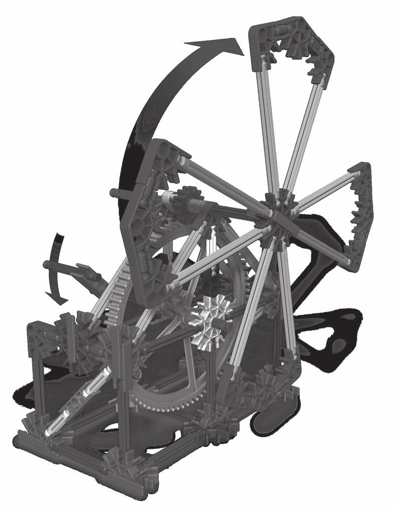
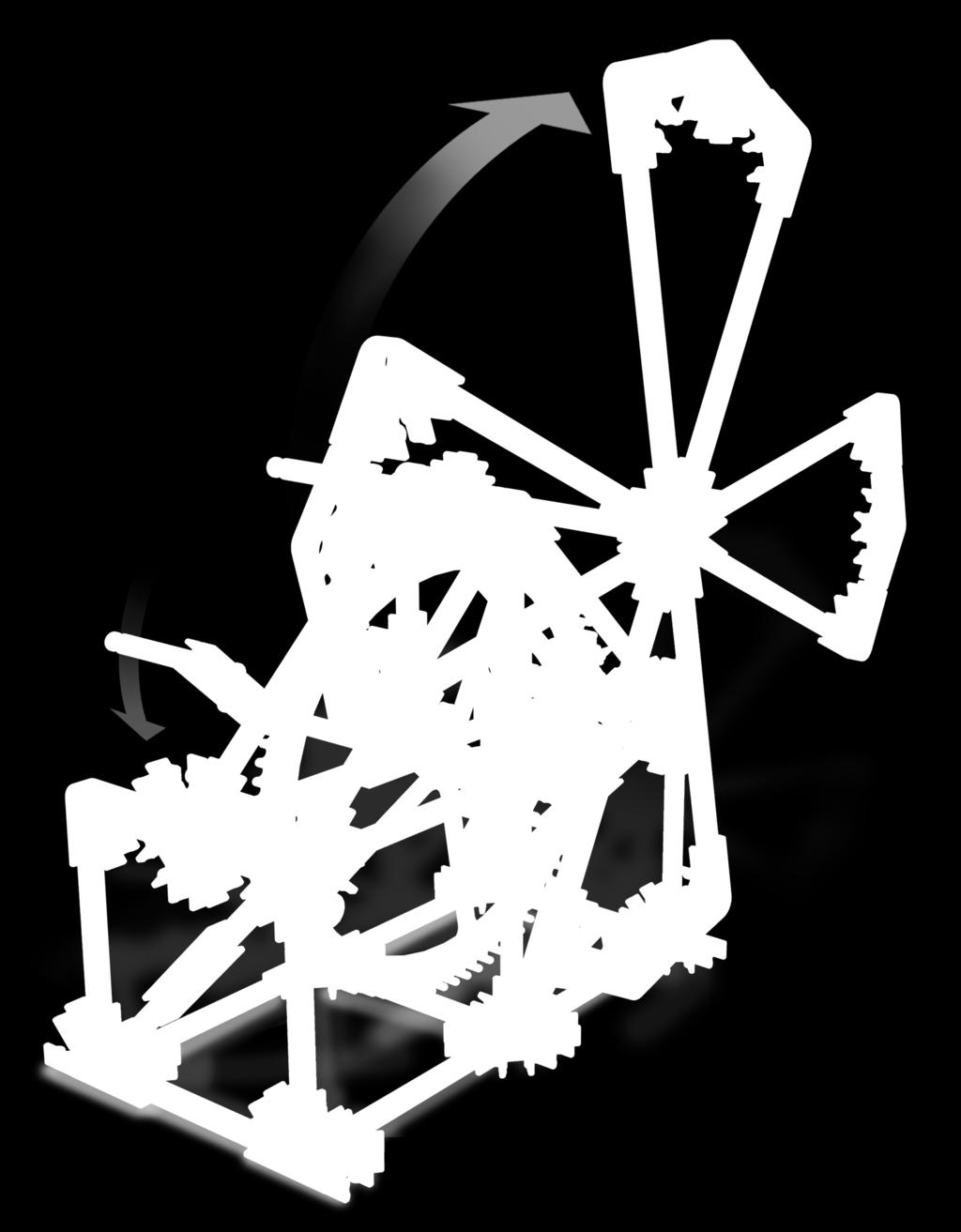
33 The Stationary Bike: An example of a chain and sprocket system. GEARS Stationary Bike OBJECTIVES Students will: 1. Build and investigate the mechanism of a model system that represents a real-life object. 2. Observe how motion and force are transmitted through a distance using a chain and sprocket system. Each student group will need: - 1 K NEX Intro To Simple Machines: Gears set with Building Instructions booklet - Student Journals MATERIALS You will need: - A bicycle (optional) PROCEDURE Introduction Review with the students how gears are connected and how energy/motion is transferred through a spur gear system. In a spur gear system, the gears are meshed and in line. Force and motion are transferred from one gear to another along this line. If your students are familiar with the term plane you can explain that the force and energy are transferred along the same plane. Remind students that a spur gear system makes work easier by changing the output speed or multiplying the output force. Remind students that they cannot use a machine to gain both speed and force. There is always a trade-off when you use a simple machine. They can gain speed at the expense of force or multiply force at the expense of speed. Ask the students to tell you what is gained, if anything, when a gear system uses gears of the same size in a gear train. Students should remember that when gears are the same size, neither speed nor force is gained. Your gain is that you may be able to change the direction of motion. Explain that a spur gear system is just one type of gear arrangement. Tell the students that they will explore another type of gear system, one in which the gears DO NOT touch. The system they will investigate is one that is used in a stationary bicycle. Education 31
34 INTRODUCTION TO SIMPLE MACHINES Discuss how the stationary bicycle s design is based on a 2-wheel bicycle. If possible provide an example of a bicycle for the students to investigate. Alternatively, ask the students to look at Pages 12 and 13 of the Building Instructions booklet to interpret how they think the mechanism works. Ask them questions about how the bicycle works and encourage them to use terms they already know that are associated with a bicycle s gear system: Where does the power come from to drive the bicycle? Foot power, via the pedals. Which parts move and what are their functions? Various answers. How is the power transferred to the rear wheel? How is the gear arrangement in this mechanism different from the spur gear system they have studied? Responses to this question will give you the opportunity to discuss the chain and sprocket drive system. Chain. The chain and sprocket drive system uses a chain to transmit rotary power from a driver axle to a driven axle. Sprockets are toothed wheels on which a chain runs. They are placed a certain distance apart but the chain links mesh with the teeth on the sprocket so that turning one gear moves the chain and thus turns the second gear. Divide the class into groups made up of 2 to 3 students. Building Activity Distribute a K NEX Gears set to each group. Ask the students to turn to Pages 12 and 13 of the Building Instructions booklet and construct the model of the STATIONARY BIKE. To save time, we suggest that one student completes Steps 1-6 at the same time as another group member completes Steps Inquiry Activity: How is motion and force transferred using a chain and sprocket system? Steps 1. (a) Following completion of the construction phase, allow students time to explore their models. Encourage the students to identify the parts of their model bicycle. (b) Using the model as an example, demonstrate on the chalkboard how to make simple labeled diagrams using arrows to show the direction of movement. See example to the right: 32 Education Chain Sprocket Direction of Movement 888-ABC-KNEX

35 GEARS Stationary Bike (c) Ask the students to sketch a diagram of their bicycles. Encourage them to give names to the various parts of their model. You can then decide whether or not to formalize these. The following terms may be helpful: Sprocket, chain, pedal, drive mechanism, links, driver gear, driven gear, driver axle, driven axle. (d) Have the students draw arrows on their diagrams to show the direction each part moves as the pedals are turned. (e) Ask the students to compare the direction of motion of the axle on the driver gear with the direction of motion of the axle on the driven gear. Both axles turn in the same direction. (f) Students should record all their observations. 2. Encourage the students to continue exploring the chain and sprocket mechanism as they answer the questions below. Ask the students to record their responses. (a) Where is the effort force applied? What type of motion is the input motion? (b) Where does the output motion take place? What type of motion is it? The effort force is applied to the pedals. The input motion is a rotational or circular motion. The output motion happens at the back wheel. The output motion is also a rotational or circular motion. (c) What is the function of the chain in this system? The chain transfers energy/motion from the gear at the pedals to the gear at the rear wheel. (d) Describe the transfer of energy/ motion through your stationary bike system. Start at the pedals and end at the rear wheel. Turning the pedals transfers motion and its energy along the driver axle to the sprocket at the front of the bike (driver gear). As the front sprocket turns, motion is transferred to the chain. The chain transfers that motion and its energy to the rear sprocket (driven gear). The turning of the driven gear turns the rear wheel. Applying The Idea NOTE: It may be helpful to have a model of the crank fan available for comparison at this point in the lesson. Ask the students to write one reason why bicycles use a chain and sprocket system rather than a spur gear system. Remind them to use their crank fan notes if they need a little refresher on spur gears. Answers will vary. Possible answer: In a spur gear system, the driven gear turns in the opposite direction to the driver gear. To go forward, you would have to pedal backwards. Education 33
2. Explore your model. Locate and identify the gears. Watch the gear mechanism in operation as you turn the crank.
 Experiment #1 79318 Using a Spur Gear System in a Crank Fan Objectives: Understand and describe the transfer of motion through a spur gear system and investigate the relationship between gear size, speed
Simple Gears and Transmission
 Simple Gears and Transmission Simple Gears and Transmission page: of 4 How can transmissions be designed so that they provide the force, speed and direction required and how efficient will the design be?
IT'S MAGNETIC (1 Hour)
") IT'S MAGNETIC (1 Hour) Addresses NGSS Level of Difficulty: 4 Grade Range: 3-5 OVERVIEW In this activity, students will create a simple electromagnet using a nail, a battery, and copper wire. They will
IT'S MAGNETIC (1 Hour) Addresses NGSS Level of Difficulty: 4 Grade Range: 3-5 OVERVIEW In this activity, students will create a simple electromagnet using a nail, a battery, and copper wire. They will
MECHANISMS. AUTHORS: Santiago Camblor y Pablo Rivas INDEX
 MECHANISMS AUTHORS: Santiago Camblor y Pablo Rivas INDEX 1 INTRODUCTION 2 LEVER 3 PULLEYS 4 BELT AND PULLEY SYSTEM 5 GEARS 6 GEARS WITH CHAIN 7 WORM GEAR 8 RACK AND PINION 9 SCREW AND NUT 10 CAM 11 ECCENTRIC
Exploration 2: How Do Rotorcraft Fly?
 Exploration 2: How Do Rotorcraft Fly? Students choose a model and use it to explore rotorcraft flight. They use a fair test and conclude that a spinning rotor is required for a rotorcraft to fly. Main
NEW CAR TIPS. Teaching Guidelines
 NEW CAR TIPS Teaching Guidelines Subject: Algebra Topics: Patterns and Functions Grades: 7-12 Concepts: Independent and dependent variables Slope Direct variation (optional) Knowledge and Skills: Can relate
Lesson Plan: Electricity and Magnetism (~100 minutes)
") Lesson Plan: Electricity and Magnetism (~100 minutes) Concepts 1. Electricity and magnetism are fundamentally related. 2. Just as electric charge produced an electric field, electric current produces a
Lesson Plan: Electricity and Magnetism (~100 minutes) Concepts 1. Electricity and magnetism are fundamentally related. 2. Just as electric charge produced an electric field, electric current produces a
Smart Spinner. Age 7+ Teacher s Notes. In collaboration with NASA
 Smart Spinner Age 7+ Teacher s Notes In collaboration with NASA LEGO and the LEGO logo are trademarks of the/sont des marques de commerce de/son marcas registradas de LEGO Group. 2012 The LEGO Group. 190912
Simple Gears and Transmission
 Simple Gears and Transmission Contents How can transmissions be designed so that they provide the force, speed and direction required and how efficient will the design be? Initial Problem Statement 2 Narrative
For 8-12 Year Olds. Fantastic Gears. Premium Worksheets For Children. Content: Marwah Illustrations: Dikhit Borah
 For 8-12 ear Olds Fantastic Gears Premium Worksheets For Children Content: Marwah Illustrations: Dikhit Borah Index Activity Name Skills Acquired Types of Gears Missing Gears Geared Vehicles Get In Gear!
CHAPTER 6 GEARS CHAPTER LEARNING OBJECTIVES
 CHAPTER 6 GEARS CHAPTER LEARNING OBJECTIVES Upon completion of this chapter, you should be able to do the following: Compare the types of gears and their advantages. Did you ever take a clock apart to
DESIGN AND TECHNOLOGY
 Candidate Name Centre Number 0 Candidate Number GCSE 142/04 DESIGN AND TECHNOLOGY PAPER 2 FOCUS AREA: SYSTEMS AND CONTROL TECHNOLOGY Higher Tier A.M. MONDAY, 2 June 2008 1 1 2 hours Leave Blank Question
Fourth Grade. Multiplication Review. Slide 1 / 146 Slide 2 / 146. Slide 3 / 146. Slide 4 / 146. Slide 5 / 146. Slide 6 / 146
 Slide 1 / 146 Slide 2 / 146 Fourth Grade Multiplication and Division Relationship 2015-11-23 www.njctl.org Multiplication Review Slide 3 / 146 Table of Contents Properties of Multiplication Factors Prime
Fourth Grade. Slide 1 / 146. Slide 2 / 146. Slide 3 / 146. Multiplication and Division Relationship. Table of Contents. Multiplication Review
 Slide 1 / 146 Slide 2 / 146 Fourth Grade Multiplication and Division Relationship 2015-11-23 www.njctl.org Table of Contents Slide 3 / 146 Click on a topic to go to that section. Multiplication Review
Exploration 4: Rotorcraft Flight and Lift
 Exploration 4: Rotorcraft Flight and Lift Students use appropriate terminology to describe the various stages of flight and discover that the lift force changes with the amount of air moved by the rotor
Based on results from TIMSS Key. bulb. bulb. switch. wir. battery. wir. switch. Lesson plan on investigative science. wire.
 bulb Based on results from TIMSS 2015 Key battery Key ba bu tte switch sw h itc bulb e wir battery switch wire bat sw Lesson plan on investigative science Electricity wir Electricity Pupils performed less
How to Build with the Mindstorm Kit
 How to Build with the Mindstorm Kit There are many resources available Constructopedias Example Robots YouTube Etc. The best way to learn, is to do Remember rule #1: don't be afraid to fail New Rule: don't
Applications in Design & Engine. Analyzing Compound, Robotic Machines
 v2.1 Compound Machines ering Applications in Design & Engine Analyzing Compound, Robotic Machines Educational Objectives At the conclusion of this lesson, students should be able to: Understand the relationship
All levers are one of three types, usually called classes. The class of a lever depends on the relative position of the load, effort and fulcrum:
 Página 66 de 232 Mechanisms A mechanism is simply a device which takes an input motion and force, and outputs a different motion and force. The point of a mechanism is to make the job easier to do. The
Your web browser (Safari 7) is out of date. For more security, comfort and. the best experience on this site: Update your browser Ignore
 is out of date. For more security, comfort and. the best experience on this site: Update your browser Ignore") Your web browser (Safari 7) is out of date. For more security, comfort and Activitydevelop the best experience on this site: Update your browser Ignore Circuits with Friends What is a circuit, and what
Your web browser (Safari 7) is out of date. For more security, comfort and Activitydevelop the best experience on this site: Update your browser Ignore Circuits with Friends What is a circuit, and what
LEGO Education WeDo 2.0 Toolbox
 LEGO Education WeDo 2.0 Toolbox WeDo 2.0 Table of Contents Program with WeDo 2.0 3-21 Build with WeDo 2.0 22-36 Program with WeDo 2.0 Programming is an important part of twenty-first century learning,
Can You Light the Bulb?
 3-5 Physical Science Southern Nevada Regional Professional Development Program Can You Light the Bulb? INTRODUCTION Electrical energy is easily transferred through loops that we call circuits. This activity
Reliable Reach. Robotics Unit Lesson 4. Overview
 Robotics Unit Lesson 4 Reliable Reach Overview Robots are used not only to transport things across the ground, but also as automatic lifting devices. In the mountain rescue scenario, the mountaineers are
Moments. It doesn t fall because of the presence of a counter balance weight on the right-hand side. The boom is therefore balanced.
 Moments The crane in the image below looks unstable, as though it should topple over. There appears to be too much of the boom on the left-hand side of the tower. It doesn t fall because of the presence
SCIENCE 8. Unit 4 Booklet. Machines and Mechanical Systems
 SCIENCE 8 Unit 4 Booklet Machines and Mechanical Systems TOPIC 1 REINFORCEMENT Levers Have Class BLM 4-2 Goal Identify items as Class 1, Class 2, or Class 3 levers. Introduction There are three classes
Technology Exploration-I Curriculum Development Unit
 Technology Exploration-I Modu le 4: Pulleys and Gears PREPARED BY Curriculum Development Unit August 2013 Applied Technology High Schools, 2013 Module 4: Pulleys and Gears Module Objectives After the completion
Driver Driven. InputSpeed. Gears
 Gears Gears are toothed wheels designed to transmit rotary motion and power from one part of a mechanism to another. They are fitted to shafts with special devices called keys (or splines) that ensure
INVESTIGATING SOLAR ENERGY TEACHER S GUIDE
 INVESTIGATING SOLAR ENERGY TEACHER S GUIDE V1-10/13 2013 K NEX Limited Partnership Group and its licensors. K NEX and is a trademark of K NEX Limited Partnership Group. www.knexeducation.com abcknex@knex.com
Graphical representation of a gear
 Homework 4 Gears Gears are designed to transmit rotary motion. Often they are arranged in a gear train (meshed together). Gear trains provide a change in speed, torque (turning force) and direction (clockwise
What Are Gears? What Do They Do?
 What Are Gears? What Do They Do? Pre-Lesson Quiz 1. What is a gear? 2. List as many examples as you can of gears or objects that use gears. 2 Pre-Lesson Quiz Answers 1. What is a gear? A gear is a wheel
Orientation and Conferencing Plan Stage 1
 Orientation and Conferencing Plan Stage 1 Orientation Ensure that you have read about using the plan in the Program Guide. Book summary Read the following summary to the student. Everyone plays with the
ROBOTICS BUILDING BLOCKS
 ROBOTICS BUILDING BLOCKS 2 CURRICULUM MAP Page Title...Section Estimated Time (minutes) Robotics Building Blocks 0 2 Imaginations Coming Alive 5...Robots - Changing the World 5...Amazing Feat 5...Activity
Lesson Plan 11 Electric Experiments
 Lesson Plan 11 Electric Experiments Brief description Students experiment with aluminium foil, batteries and cheap, readily availably low voltage light bulbs* to construct a simple conductivity tester.
Engaging Inquiry-Based Activities Grades 3-6
 ELECTRICITY AND CIRCUITS Engaging Inquiry-Based Activities Grades 3-6 Janette Smith 2016 Janette Smith 2016 1 What s Inside Activity 1: Light it Up!: Students investigate different ways to light a light
DESIGN AND TECHNOLOGY
 Candidate Name Centre Number 0 Candidate Number GCSE 142/02 DESIGN AND TECHNOLOGY PAPER 2 FOCUS AREA: SYSTEMS AND CONTROL TECHNOLOGY Foundation Tier A.M. MONDAY, 2 June 2008 1 1 2 hours Leave Blank Question
Rocket Races. Rocket Activity. Objective Students investigate Newton s third law of motion by designing and constructing rocketpowered
 Rocket Activity Rocket Races Objective Students investigate Newton s third law of motion by designing and constructing rocketpowered racing cars. National Science Content Standards Unifying Concepts and
2010 National Edition correlated to the. Creative Curriculum Teaching Strategies Gold
 2010 National Edition correlated to the Creative Curriculum Teaching Strategies Gold 2015 Big Day for PreK is a proven-effective comprehensive early learning program that embraces children's natural curiosity
Busy Ant Maths and the Scottish Curriculum for Excellence Foundation Level - Primary 1
 Busy Ant Maths and the Scottish Curriculum for Excellence Foundation Level - Primary 1 Number, money and measure Estimation and rounding Number and number processes Fractions, decimal fractions and percentages
Simplifying Electricity
 Simplifying Electricity Fundamentals of electricity LK6816 www.matrixtsl.com Copyright 2014 Matrix Technology Solutions Ltd TEACHER S NOTES Fundamentals of Electricity The Locktronics Fundamentals of Electricity
What Is an Electric Motor? How Does a Rotation Sensor Work?
 What Is an Electric Motor? How Does a Rotation Sensor Work? Electric Motors Pre-Quiz 1. What is an electric motor? 2. Name two applications (things) you use every day that use electric motors. 3. How does
Gear Ratios and Speed Background Material
 VEX Robotics Lab 3 How Do Gear Ratios Affect and Torque? Introduction In this investigation, students will learn the relationships between gear ratio, axle speed, and torque. Students will use the Vex
ELECTRIC CURRENT. Name(s)
") Name(s) ELECTRIC CURRT The primary purpose of this activity is to decide upon a model for electric current. As is the case for all scientific models, your electricity model should be able to explain observed
Name(s) ELECTRIC CURRT The primary purpose of this activity is to decide upon a model for electric current. As is the case for all scientific models, your electricity model should be able to explain observed
Engineering Diploma Resource Guide ST280 ETP Hydraulics (Engineering)
") Engineering Diploma Resource Guide ST80 ETP Hydraulics (Engineering) Introduction Hydraulic systems are a fundamental aspect of engineering. Utilised across a variety of sectors including aviation, construction,
Engineering Diploma Resource Guide ST80 ETP Hydraulics (Engineering) Introduction Hydraulic systems are a fundamental aspect of engineering. Utilised across a variety of sectors including aviation, construction,
TECHNOLOGY. Grade 8. Learner Teacher. Systems and Control (Mechanisms) Hoërskool Gerrit Maritz District D15
 Hoërskool Gerrit Maritz District D15") TECHNOLOGY Systems and Control (Mechanisms) Hoërskool Gerrit Maritz District D15 2009 Grade 8 Learner Teacher CAPABILITY TASK In this module you are going to make a mechanism to help a disabled boom operator
TECHNOLOGY Systems and Control (Mechanisms) Hoërskool Gerrit Maritz District D15 2009 Grade 8 Learner Teacher CAPABILITY TASK In this module you are going to make a mechanism to help a disabled boom operator
ECSE-2100 Fields and Waves I Spring Project 1 Beakman s Motor
 Names _ and _ Project 1 Beakman s Motor For this project, students should work in groups of two. It is permitted for groups to collaborate, but each group of two must submit a report and build the motor
Module 3: Wheel & Axle
 Technology Exploration-I Module 3: Wheel & Axle PREPARED BY Curriculum Development Unit August 2013 Applied Technology High Schools, 2013 Module 3: Wheel & Axle Module Objectives After the completion of
4 What We Know About Fuel Cells
 Build Knowledge 4 What We Know About Fuel Cells MAKING CONNECTIONS This activity can serve as an introduction to some of the materials that will be available to students as they respond to the RFP. TEACHER
SUBJECT AREA(S): Amperage, Voltage, Electricity, Power, Energy Storage, Battery Charging
: Amperage, Voltage, Electricity, Power, Energy Storage, Battery Charging") Solar Transportation Lesson 4: Designing a Solar Charger AUTHOR: Clayton Hudiburg DESCRIPTION: In this lesson, students will further explore the potential and challenges related to using photovoltaics
Solar Transportation Lesson 4: Designing a Solar Charger AUTHOR: Clayton Hudiburg DESCRIPTION: In this lesson, students will further explore the potential and challenges related to using photovoltaics
Electromagnetic Induction (approx. 1.5 h) (11/9/15)
 (11/9/15)") (approx. 1.5 h) (11/9/15) Introduction In 1819, during a lecture demonstration, the Danish scientist Hans Christian Oersted noticed that the needle of a compass was deflected when placed near a current-carrying
(approx. 1.5 h) (11/9/15) Introduction In 1819, during a lecture demonstration, the Danish scientist Hans Christian Oersted noticed that the needle of a compass was deflected when placed near a current-carrying
MiSTE STEM Camp Solar Lesson July, 2016 Standard(s) Learning targets Assessment Essential vocabulary. Informal - Discussion and participation
 Learning targets Assessment Essential vocabulary. Informal - Discussion and participation") MiSTE STEM Camp Solar Lesson July, 2016 Standard(s) Learning targets Assessment Essential vocabulary Science SEPS.1 - I can clarify problems to determine criteria for possible solutions. Science SEPS.8
MiSTE STEM Camp Solar Lesson July, 2016 Standard(s) Learning targets Assessment Essential vocabulary Science SEPS.1 - I can clarify problems to determine criteria for possible solutions. Science SEPS.8
ACTIVITY 1: Electric Circuit Interactions
 CYCLE 5 Developing Ideas ACTIVITY 1: Electric Circuit Interactions Purpose Many practical devices work because of electricity. In this first activity of the Cycle you will first focus your attention on
Stay Safe Around Electricity Teacher s Guide
 Stay Safe Around Electricity Teacher s Guide INTRODUCTION The Stay Safe Around Electricity activity booklet can be used as a follow-up to an electric utility presentation or as a stand-alone piece to teach
Pros and cons of hybrid cars
 GRADE 7 Hybrid cars are increasingly popular. In this lesson, students investigate the costs and benefits of using hybrid cars over gasoline-powered cars by comparing the cost and environmental impact
LETTER TO PARENTS SCIENCE NEWS. Dear Parents,
 LETTER TO PARENTS Cut here and paste onto school letterhead before making copies. Dear Parents, SCIENCE NEWS Our class is beginning a new science unit using the FOSS Magnetism and Electricity Module. We
Compound Gears Laboratory - Part 2
 Compound Gears Laboratory - Part 2 Names: Date: About this Laboratory In this laboratory, you will explore compound gear trains, gear ratios, and how the number of teeth on a drive and driven gear affect
Mechanical Systems. Section 1.0 Machines are tools that help humans do work. 1.1 Simple Machines- Meeting Human Needs Water Systems
 Unit 4 Mechanical Systems Section 1.0 Machines are tools that help humans do work. Define: machine- 1.1 Simple Machines- Meeting Human Needs Water Systems Then: Now: The earliest devices were devices.
Section 4 WHAT MAKES CHARGE MOVE IN A CIRCUIT?
 Section 4 WHAT MAKES CHARGE MOVE IN A CIRCUIT? INTRODUCTION Why does capacitor charging stop even though a battery is still trying to make charge move? What makes charge move during capacitor discharging
Grade 8 Science. Unit 4: Systems in Action
 Grade 8 Science Unit 4: Systems in Action Machines That Turn Last class we looked at the idea of a boat winch, a wheel and axle used to get a boat out of the water, onto a trailer. You rotate the handle
Newton Scooters TEACHER NOTES. Forces Chapter Project. Materials and Preparation. Chapter Project Overview. Keep Students on Track Section 2
 TEACHER NOTES Lab zonetm Newton Scooters The following steps will walk you through the. Use the hints as you guide your students through planning, construction, testing, improvements, and presentations.
MECHANICAL SYSTEMS - Reference Page
 ANSWER KEY Student Class MECHANICAL SYSTEMS - Reference Page Refer to the following Formulas that you may need to use throughout this exam Science I n Action 8 Mechanical Systems UNIT Test Numerical Response
Experimental Procedure
 1 of 19 9/10/2018, 11:03 AM https://www.sciencebuddies.org/science-fair-projects/project-ideas/robotics_p023/robotics/line-following-robot (http://www.sciencebuddies.org/science-fair-projects/projectideas/robotics_p023/robotics/line-following-robot)
Understanding Electricity and Electrical Safety Teacher s Guide
 Understanding Electricity and Electrical Safety Teacher s Guide Note to Instructor: The activities and experiments in this booklet build on each other to develop a student s understanding of electricity
UTCRS ELEMENTARY STEM CURRICULUM
 UTCRS ELEMENTARY STEM CURRICULUM Table of Contents Objectives... 4 Texas Essential Knowledge and Skills (TEKS) and National Standards... 4 TEKS Science 3-5... 4 TEKS Math 3-5... 5 International Technology
Electrical Circuits. Vanderbilt Student Volunteers for Science. Training Presentation VINSE/VSVS Rural
 Electrical Circuits Vanderbilt Student Volunteers for Science Training Presentation 2018-2019 VINSE/VSVS Rural Important! Please use this resource to reinforce your understanding of the lesson! Make sure
Math Geometry circle diameter Measurement length
 Topic Simple machines Key Question What simple machines are found in an internal combustion engine? Learning Goals Students will: construct a working model of an internal combustion engine that has a piston,
Instructionally Relevant Alternate Assessments for Students with Significant Cognitive Disabilities
 Instructionally Relevant Alternate Assessments for Students with Significant Cognitive Disabilities Neal Kingston, Karen Erickson, and Meagan Karvonen Background History of AA-AAS as separate from instruction
SCI ON TRAC ENCEK WITH
 WITH TRACK ON SCIENCE PART 1: GET GOING! What s It About? The Scout Association has partnered with HOT WHEELS, the COOLEST and most iconic diecast car brand to help Beavers and Cubs explore FUN scientific
MODULE 6 Lower Anchors & Tethers for CHildren
 National Child Passenger Safety Certification Training Program MODULE 6 Lower Anchors & Tethers for CHildren Topic Module Agenda: 50 Minutes Suggested Timing 1. Introduction 2 2. Lower Anchors and Tether
Chapter 7: DC Motors and Transmissions. 7.1: Basic Definitions and Concepts
 Chapter 7: DC Motors and Transmissions Electric motors are one of the most common types of actuators found in robotics. Using them effectively will allow your robot to take action based on the direction
Using Hydraulic Systems
 Lesson A6 7 Using Hydraulic Systems Unit A. Mechanical Systems and Technology Problem Area 6. Agricultural Power Systems Lesson 7. Using Hydraulic Systems New Mexico Content Standard: Pathway Strand: Power,
1. What are some everyday examples (that are NOT listed above) in which you use torque to complete a task?
 in which you use torque to complete a task?") ID: NAME: DATE: CLASS: Chapter 11: Torque Notes POGIL #1 REMEMBER: Throughout this paper, you will see some symbols. The stop sign means STOP and check with a teacher before continuing. The key means THIS
ID: NAME: DATE: CLASS: Chapter 11: Torque Notes POGIL #1 REMEMBER: Throughout this paper, you will see some symbols. The stop sign means STOP and check with a teacher before continuing. The key means THIS
Name Date Period. MATERIALS: Light bulb Battery Wires (2) Light socket Switch Penny
 Light socket Switch Penny") Name Date Period Lab: Electricity and Circuits CHAPTER 34: CURRENT ELECTRICITY BACKGROUND: Just as water is the flow of H 2 O molecules, electric current is the flow of charged particles. In circuits of
Name Date Period Lab: Electricity and Circuits CHAPTER 34: CURRENT ELECTRICITY BACKGROUND: Just as water is the flow of H 2 O molecules, electric current is the flow of charged particles. In circuits of
Renewable Energy Endurance Marathon
 Next Generation Science Standards NGSS Science and Engineering Practices: Asking questions and defining problems Developing and using models Planning and carrying out investigations Analyzing and interpreting
School Transportation Assessment
 Grade: K-12 Version 1 April 2015 School Transportation Assessment SCHOOL BUS Evaluate the carbon emissions from daily transportation related to your school and identify strategies for more sustainable
Electromagnets ENERGY USE AND DELIVERY LESSON PLAN 3.3. Public School System Teaching Standards Covered
 ENERGY USE AND DELIVERY LESSON PLAN 3.3 Electromagnets This lesson is designed for 3rd 5th grade students in a variety of school settings (public, private, STEM schools, and home schools) in the seven
Renewable Energy Sprint
 Next Generation Science Standards NGSS Science and Engineering Practices: Asking questions and defining problems Developing and using models Planning and carrying out investigations Analyzing and interpreting
MONTANA TEEN DRIVER CURRICULUM GUIDE Lesson Plan & Teacher Commentary. Module 2.1 Preparing to Drive
 MONTANA TEEN DRIVER CURRICULUM GUIDE Lesson Plan & Teacher Commentary Module 2.1 Preparing to Drive Lesson Objective (from Essential Knowledge and Skills Topics): Identifying Vehicle Gauges, Alert and
Scholastic s Early Childhood Program correlated to the Kentucky Primary English/Language Arts Standards
 Primary English/Language Arts Reading (1.2) Arts and Humanities (2.24, 2.25) Students develop abilities to apply appropriate reading strategies to make sense of a variety of print and nonprint texts (literary,
reflect energy: the ability to do work
 reflect Have you ever thought about how much we depend on electricity? Electricity is a form of energy that runs computers, appliances, and radios. Electricity lights our homes, schools, and office buildings.
Solar Matters III Teacher Page
 Solar Matters III Teacher Page Junior Solar Sprint Wheels, Axles & Bearing Student Objective The student: given a scenario of a design with wheels, will be able to predict how the design will function
Cable Car. Category: Physics: Balance & Center of Mass, Electricity and Magnetism, Force and Motion. Type: Make & Take.
 Cable Car Category: Physics: Balance & Center of Mass, Electricity and Magnetism, Force and Motion Type: Make & Take Rough Parts List: 1 Paperclip, large 2 Paperclips, small 1 Wood stick, 1 x 2 x 6 4 Electrical
Timing Belt Selection Using Visual Basic
 3225 Timing Belt Selection Using Visual Basic Edward M. Vavrek Purdue University North Central Abstract Timing belts are used in many different machine applications. The sizing and selection of an appropriate
Circuit Concepts (Residential)
") Youth Explore Trades Skills Circuit Concepts (Residential) Description This Activity Plan will allow students to understand how electrical circuits work in a home. Students will also gain knowledge of
Youth Explore Trades Skills Circuit Concepts (Residential) Description This Activity Plan will allow students to understand how electrical circuits work in a home. Students will also gain knowledge of
Fluid Power Lab. What s inside? This lab will provide you with experiences in and an understanding of: Cylinders. Friction
 Revision 4.2 luid Power Lab Name: Set: Date: Version: English Measurement System (inches & pounds). metric version also available. What s inside? This lab will provide you with experiences in and an understanding
Mechanics and Mechanisms. What is do you think about when you hear the word mechanics? Mechanics. Is this a mechanism? 2/17/2011
 Mechanics and Mechanisms What is do you think about when you hear the word mechanics? Mechanics Mechanics is the study of how things move Is this a mechanism? Concerned with creating useful movement through
Engineering Design Process for BEST Robotics JANNE ACKERMAN COLLIN COUNTY (COCO) BEST & BEST OF TEXAS ROBOTICS
 BEST & BEST OF TEXAS ROBOTICS") Engineering Design Process for BEST Robotics JANNE ACKERMAN COLLIN COUNTY (COCO) BEST & BEST OF TEXAS ROBOTICS Agenda Getting Started Lessons Learned Design Process Engineering Mechanics 2 Save Time Complete
Engineering Design Process for BEST Robotics JANNE ACKERMAN COLLIN COUNTY (COCO) BEST & BEST OF TEXAS ROBOTICS Agenda Getting Started Lessons Learned Design Process Engineering Mechanics 2 Save Time Complete
Simplifying Electricity
 Simplifying Electricity Fundamentals of electricity LK6816 www.matrixmultimedia.com Copyright 2009 Matrix Multimedia Limited TEACHER S NOTES Introduction Congratulations! You have just bought one of the
Is it Magnetic? 1. Fill in each table. List things ATTRACTED by a magnet on the LEFT and things NOT ATTRACTED on the RIGHT.
 Is it Magnetic? 1. Fill in each table. List things ATTRACTED by a magnet on the LEFT and things NOT ATTRACTED on the RIGHT. MAGNETIC NON-MAGNETIC # Object Made from check # Object Made from check --- ------------
Electricity and. Circuits Science Unit 1. For Special Education. Created by Positively Autism. Hands-On Low Prep Easy to Use
 Electricity and Circuits Science Unit 1 For Special Education Hands-On Low Prep Easy to Use Created by Positively Autism Making Learning Fun and Meaningful for Children with Autism Thank You for Downloading
Gain an understanding of how the vehicles work. Determine the advantages and disadvantages of each
 Title- Alternative Energy Races Subject/s and Grade Level/s- Overview- Earth Science or Physics, Grades 7-9. This lesson demonstrates the operation of alternative energy vehicles, namely hydrogen fuel
Inquiry-Based Physics in Middle School. David E. Meltzer
 Inquiry-Based Physics in Middle School David E. Meltzer Mary Lou Fulton Teachers College Arizona State University Mesa, Arizona U.S.A. Supported in part by a grant from Mary Lou Fulton Teachers College
Q1. Figure 1 shows a straight wire passing through a piece of card.
 THE MOTOR EFFECT Q1. Figure 1 shows a straight wire passing through a piece of card. A current (I) is passing down through the wire. Figure 1 (a) Describe how you could show that a magnetic field has been
Crazy Contraptions Activity Guide
 Crazy s Activity Guide Page 1 Revision 3.0 1. Ball rolls down ramps onto lever 2. Lever pivots and tosses dime 3. Dime lands in funnel and falls onto 2nd lever 4. Ramp tilts and car rolls down it into
Stopping distance = thinking distance + braking distance.
 Q1. (a) A driver may have to make an emergency stop. Stopping distance = thinking distance + braking distance. Give three different factors which affect the thinking distance or the braking distance. In
Teacher s Guide. CHOKE HAZARD - Small parts. Not for children under 3 years. S o l a r E n e r g y
 S o l a r E n e r g y Teacher s Guide KNX 96191-V2 2008 K'NEX Limited Partnership Group and its licensors. K NEX Limited Partnership Group P.O. Box 700 Hatfield, PA 19440-0700 Visit our website at www.knexeducation.com
Total: Allow six to seven class periods for project planning, designing, building, and presenting.
 Unit 1350 Keeping it Safe: An Electrical Security System Summary In this lesson, teams of three or four students will apply their knowledge of electric charge, energy sources, and series and parallel electric
Solar Kit Lesson #13 Solarize a Toy
 UCSD TIES adapted from NYSERDA Energy Smart www.schoolpowernaturally.org Solar Kit Lesson #13 Solarize a Toy TEACHER INFORMATION LEARNING OUTCOME After designing and constructing solar electric power sources
Porsche unveils 4-door sports car
 www.breaking News English.com Ready-to-use ESL / EFL Lessons Porsche unveils 4-door sports car URL: http://www.breakingnewsenglish.com/0507/050728-porsche-e.html Today s contents The Article 2 Warm-ups
Introduction: Electromagnetism:
 This model of both an AC and DC electric motor is easy to assemble and disassemble. The model can also be used to demonstrate both permanent and electromagnetic motors. Everything comes packed in its own
Mechanical Power Transmission. September 16, 2008
 2008 TE Sessions Supported by Mechanical Power Transmission September 16, 2008 www.robojackets.org Goals Hand out kits to teams that don t have one. More physics concepts and terms Understanding key devices