Service Manual. Fuller Medium Heavy Transmissions TRSM0201 October 2007
|
|
|
- Ruby O’Brien’
- 5 years ago
- Views:
Transcription
1 Service Manual Fuller Medium Heavy Transmissions TRSM0201 October 2007
2
3 Model Designations...2 Description...3 Specifications...4 Lubrication...5 Conversion to Overdrive...6 Clutch Shaft Replacement...6 General Precautions for Disassembly...6 Detailed Disassembly Instructions...7 Exploded Views Drive Gear...8 Countershafts...11 Reverse Idler Shaft...11 Reverse Idler Gear and Shaft...14 Mainshaft...14 Tailshaft...14 Tailshaft and Rear Bearing Cover...17 Shifting Bar Housing...17 Inspection...17 Torque Ratings...21 Gasket Location...21 Preventative Maintenance Check Chart...25 General Precautions for Reassembly...25 Detailed Reassembly Instructions...25 Tool Reference...25 Gear Chart for Part Numbers...26

4 DESCRIPTION CUTAWAY OF FIVE SPEED TWIN-COUNTERSHAFT TRANSMISSION 2
5 MODEL DESIGNATIONS MODEL DESIGNATIONS T = Twin Countershaft Type O = Used as a letter, denotes overdrive model 09 = 900 lbs. ft. capacity rating 05 = Five speeds A, B. etc. = Following numbers indicates a specific set of ratios Since the models in the T-905 series are identical in construction, references in this manual apply to all models unless stated otherwise. This includes models not listed above which may have other ration combinations, designated by letters following the numerals. PART NUMBERS SHOWN IN THIS MANUAL ARE SUBJECT TO CHANGE AND APPLY ONLY AT TIME OF PRINTING. 3


6 DESCRIPTION The T-905 model transmissions have five forward speeds and one reverse speed, and are designed for heavy duty vehicles. These models are of twin countershaft design which divides the torque equally between shafts and gears, providing a high capacity to weight ratio. The countershafts, identical except for the PTO gears, are short and bearings are of a relative low capacity due to the split torque principle. All gears have spur type teeth. The mainshaft floats free, receiving only minor radial loads. Mainshaft vertical displacement to conform to clutched gear position is allowed by rod-like springs which resist float to right or left. The mainshaft gears are not jounalled to the mainshaft, but are located axially by washers and held in position by rotation of the countershaft gears; this eliminates the need for bushings and sleeves. Because of equal tooth loading on each side of gear, pressure is reduced and gear face width can be narrowed. Gears are clutched by internal splines in hubs of gears. The sliding clutch gears with short, conical clutching teeth provide shorter and easier shifts. The input shaft and drive gear are not integral, thus they can be changed individually. 4
7 DESCRIPTION 5
8 SPECIFICATIONS SPECIFICATIONS SPEEDOMETER DRIVE GEAR RATIOS Clutch Release Mechanism T-905A T-905B TO-905A TO-905B Fifth Fourth Third Second First Reverse SEE PAGE 68 Clutch release bearing carrier, release bearing, extended front bearing cover, release yoke and pedal shafts furnished with transmission for use with single or two plate, push type clutches. Flat type front bearing cover furnished for use with single or two plate, pull type clutches. Provision is made in the rear bearing cover for the installation of speedometer gears and the attachment of cable. MAGNETIC OIL CLEANERS Two magnetic discs are installed in bottom of case to catch and hold metallic particles deposited in the oil. OIL CAPACITY Approximately 22 pints, depending on inclination of transmission and engine. Twenty-two pints is a zero degree measurement. Nominal torque rating 900 foot-pounds Clutch housing size SAE No. 1 or 2 Power Take-Off Openings Bottom: SAE standard heavy-duty type, short length. Right Side: SAE standard regular-duty type, short length. PTO Drive Gear Bottom: A 47-Tooth, 6/8 pitch gear on the left counterhshaft. Right Side: A 45-Tooth, 6/8 pitch gear on the right countershaft. PTO Drive Gear Speeds Both turning at.533 engine speed on T-905A and T- 905B models; and at.820 engine speed on TO-905A, and.619 on TO-905B models. Weight, with grey iron case Length From face of clutch housing to rear shoulder of mainshaft From face of clutch housing to front of companion flange hub 478 pounds 27-19/32 inches 24-23/32 inches 6
 Shifting Diagram for")

9 SPECIFICATIONS (SHIFTING DIAGRAMS) Shifting Diagram for T-905 Model Transmissions Shifting Diagram for TO-905 Model Transmissions 7
10 LUBRICATION Proper lubrication procedures are the key to a good allround maintenance program. If the oil is not doing its job, or if the oil level is ignored, all the maintenance procedures in the world are not going to keep the transmission running or assure long transmission life. Oil is important, because here are some of the things it must do: Provide a protective film - to protect surface of heavily loaded parts such as gear teeth and bearings, thus preventing metal to metal contact which causes scoring, scuffing and seizure. Act as a coolant - to dissipate heat. Have sufficient fluidity - to follow, coat and cushion all loaded surfaces. First 3,000-5,000 miles ( Km) Every 5,000 miles (8045 Km) Every 50,000 miles (80,450 Km) First 30 hours First 40 hours Every 500 hours LUBRICATION CHANGE AND INSPECTION HIGHWAY USE Change transmission oil on new units. Inspect oil level. Check for leaks. Change transmission oil. OFF-HIGHWAY Change transmission oil on new units. Inspect oil level. Check for leaks. Change transmission oil where severe dirt conditions exist. Be chemically stable - to withstand heat and agitation without separation, gumming-up, oxidizing or corroding. Be non-foaming - to prevent excessive foam and increased volume under severe conditions. Be free of sediment and water - to prevent sludge and rust. Fuller Transmissions are designed so that the internal parts operate in a bath of oil circulated by the motion of gears and shafts. Grey iron parts have built-in channels where needed, to help lubricate bearings and shafts. Thus, all parts will be amply lubricated if these procedures are closely followed: 1. Maintain oil level. Inspect regularly. 2. Change oil regularly. 3. Use the correct grade and type of oil. 4. Buy from a reputable dealer. Every 1,000 hours Miscellaneous Lubricants Change transmission oil (Normal offhighway use). Change Oil Filter Element, If So Equipped, At Each Oil Change. RECOMMENDED LUBRICANTS ON-HIGHWAY VEHICLES TYPE GRADE TEMPERATURE Heavy Duty Engine Oil MIL-L- 2104C, or MIL-L-46152, or API-SE, or API-CC SAE 50 or SAE 40 SAE 30 Mineral Gear Oil SAE 90 SAE 80W Heavy Duty Engine Oil MIL-L- 2104C, or MIL-L-46152, or API-SE, or API-CC OFF-HIGHWAY SAE 50 or SAE 40 SAE 30 Above + 10 F. (-12.5 C.) Below + 10 F. Above + 10 F. Below + 10 F. Above + 10 F. Below + 10 F. Special Recommendation - For extreme cold weather where temperature is consistently below 0 F. Heavy Duty Engine Oil MIL-L- 2104C, or MIL-L-46152, or API-SE, or API-CC SAE 20W Below 0 F. (-18 C.) O-Rings and Surfaces - Dowing Corning #200 Silicone, 30,000 Centistokes. Union Carbide L-45 Silicone, 30,000 Centistokes. 8

11 Lubrication Proper Oil Level Make sure oil is level with filler opening. Because you can reach oil with your finger does not mean oil is at proper level. Draining Oil Drain transmission while oil is warm. To drain oil, remove the drain plug at bottom of case. Clean the drain plug before re-installing. Refilling Clean area around filler plug and remove plug from side of case. Fill transmission to the level of the filler opening. If transmission has two filler openings, fill to level of rear opening on single countershaft models; fell to level of both openings on twin countershaft models. The exact amount of oil will depend on the transmission inclination and model. In every instance, fill to the level of the filler opening. Do not over fill. This will cause oil to be forced out of the case through mainshaft openings. Adding Oil It is recommended that types and brands of oil should not be intermixed because of possible incompatibility. Operating Temperature It is important that the transmission operating temperature does not exceed 250 F. (120 C.) for an extended period of time. Operating temperatures above 250 F. will cause breakdown of the oil and shorten transmission life. The following conditions in any combination can cause operating temperatures of over 250 F: (1) Operating consistently at roadspeeds under 20 MPH, (2) High engine RPM, (3) High ambient temperature, (4) Restricted air flow around transmission, (5) Exhaust system too close to transmission, (6) high horsepower, over-drive operation. High operating temperatures may require more frequent oil changes. External cooler kits are available to keep the transmission operating temperature under 250 F. when the conditions described above are encountered. If the transmission operating angle is more than 12 degrees, improper lubrication can occur. The operating angle is the transmission mounting angle in the chassis plus the percent of upgrade (expressed in degrees). The above chart illustrates the safe percent of upgrade on which the transmission can be used with various chassis mounting angles. For example: If you have a 4 degree transmission mounting angel, then 8 degrees (or 14 percent of grade) is equal to the limit of 12 degrees. If you have a 0 degree mounting angle, the transmission can be operated on a 12 degree (21 percent) grade. Anytime the transmission operating angle of 12 degrees is exceeded for an extended period of time the transmission should be equipped with an oil pump or cooler kit to insure proper lubrication. Note on the chart the effect low oil levels can have on safe operating angles. Allowing the oil level to fall ½ below the filler plug hole reduces the degree of grade by approximately 3 degrees (5.5) PROPER LUBRICATION LEVELS ARE IMPORTANT! 9

12 CONVERSION TO OVERDRIVE TO CONVERT FROM T-905A To To convert from a T-905A or T-905B to an overdrive model TO-905A or TO-905B the 4th speed gear on the mainshaft and mating gears, one on each countershaft, are interchanged with the main drive gear and mating countershaft drive gears. TO-905A, or T-905B to TO-905B The transmission must be completely disassembled as the countershaft gears must be removed and interchanged. Extra parts, other than gaskets are not needed to make the conversion. A new drive gear bearing nut may be needed as this part may be damaged during removal. 10
13 SPECIAL PROCEDURE FOR CHANGING THE CLUTCH (INPUT) SHAFT In some case it may be necessary to remove only the input shaft due to clutch wear on the splines. In these cases, the input shaft can be removed without disassembling the transmission other than removing the shift bar housing. Removal of the clutch housing is optional. The following is the detailed procedure: Disassembly 1. Remove the gear shift lever housing and shift bar housing from transmission. 2. Remove the front bearing cover. 3. Remove the drive gear bearing nut. 4. Move the drive gear assembly as far forward as possible and remove the drive gear bearing. 5. Remove the spacer from input shaft. 6. From the front, remove the snap ring from ID of drive gear. 7. Pull the input shaft forward and from splines of drive gear. 7. Peen nut into milled slot in shaft. 8. Re-install front bearing cover, shifting bar housing and gear shift lever housing. NOTE: The above instructions are for changing the input shaft only. To change the drive gear, removal of the mainshaft and countershaft bearings is necessary. Reassembly 1. Install new input shaft into splines of drive gear just far enough to expose snap ring groove in ID of drive gear. 2. Install snap ring in ID of drive gear. 3. Install spacer on shaft. 4. IMPORTANT - To prevent damaging the front quill when installing bearing, move the 4th & 5th speed sliding clutch gear forward to contact end of input shaft in hub of drive gear. Block between rear of sliding clutch and front of the 4th speed gear. When installing bearing this will hold input shaft away from quill. 5. Install drive gear bearing on shaft and into case bore, making sure blocking remains in place. 6. Remove blocking from mainshaft and install the drive gear bearing nut, left-hand thread. Use Loctite sealant on threads of nut and shaft. 11

14 DISASSEMBLY PRECAUTIONS GENERAL PRECAUTIONS FOR DISASSEMBLY Important: Read this section before starting the detailed disassembly procedures. It is assumed in the detailed disassembly instructions that the transmission lubricant has been drained and the transmission has been removed from the chassis. Removal of the gear shift lever housing assembly is included in the detailed instructions; however, this assembly must also be removed from transmission before removing unit from vehicle. Follow each procedure closely in each section, making use of both the text and pictures. 1. BEARINGS - Carefully wash and relubricate all bearings as removed and protectively wrap until ready for use. Remove bearings with pullers designed for this purpose. 2. SNAP RINGS - Remove snap rings with pliers designed for this purpose. Rings removed in this manner can be reused. 3. INPUT SHAFT - The clutch or input shaft can be removed without removing the countershafts or mainshaft (Refer to Page 11). 4. CLEANLINESS - Provide a clean place to work. It is important that no dirt or foreign material enters the unit during repairs. The outside of the unit should be carefully cleaned before starting the disassembly. Dirt is abrasive and can damage bearings. 5. WHEN DRIVING - Apply force to shafts, housings, etc., with restraint. Movement of some parts is restricted. Do not apply force after the part being driven stops solidly. Use soft hammers and bars for all disassembly work. 12
. 2.")

. 7.")
15 DETAILED DISASSEMBLY INSTRUCTIONS DETAILED DISASSEMBLY INSTRUCTIONS A. To Remove and Disassemble the Gear Shift Lever Housing Assembly 1. Turn out the four capscrews and lift the gear shift lever housing, or remote control housing, from the shifting bar housing (See Illustration 1). 2. Remove the ball grip and rubber dust cover from the gear shift lever. 3. Mount the assembly in a vise with the large bottom opening upwards. #1 - Lifting gear shift lever housing from shifting bar housing. 4. Free the tension spring by twisting a heavy screwdriver between spring and housing, forcing spring from its seat in housing (See Illustration 2). 5. Remove the tension spring from housing. 6. Withdraw the tension spring washer and gear shift lever out through bottom housing (See Illustration 3). 7. Remove nut and lockwasher from pivot pin. 8. Remove pivot pin by forcing it inward and through wall of housing. #2 - Removing the gear shift lever tension spring from under lugs cast in housing. #3 - Removing washer and gear shift lever from housing. 13


16 DISASSEMBLY #4 - Lifting the shifting bar housing from transmission. #7 - Removing interlock pin from neutral notch in the 2nd & 3rd speed shifting bar. #5 - Removing shifting bar tension springs. #8 - Two interlock balls are located in front boss, one between each bar. I#6 - Pulling the 4th-5th speed shifting bar from housing. #9 - Turning companion flange nut from output shaft. 14
. C.")
17 DISASSEMBLY B. To Remove the Shifting Bar Housing Assembly 1. Turn out the attaching capscrews. 2. Jar to break the gasket seal and lift the shifting bar housing from transmission (See Illustration #4). C. To Disassemble the Shifting Bar Housing Assembly NOTE: Lay all parts on a clean bench in the order in which they are removed to facilitate reassembly. Keep bars not being removed in the neutral position or interlock parts will lock bars. 1. Turn out the two capscrews and remove the tension spring cover from top of housing. 2. Remove the three tension springs from bores in housing (See Illustration #5). D. To Remove the Companion Flange or Yoke 1. Lock the mainshaft by engaging two speeds with the mainshaft sliding clutch gears. 2. Turn the elastic stop nut from the output shaft (See Illustration #9). 3. Pull the flange or yoke from splines of the tailshaft. E. To Remove and Disassemble the Rear Bearing Cover Assembly 1. Turn out the attaching capscrews from the rear bearing cover. 2. Pry the bearing cover evenly to the rear to unseat from tailshaft bearing (See Illustration #10). 3. Tilt housing and remove the tension balls installed under the springs. 4. Place the housing in a vise with the left side up; the long bar will be at the bottom. 5. Cut lockwire and remove lockscrews from each bar just prior to its removal. 6. Move the top, 4th-5th speed shifting bar to the front and out of housing, removing shifting yoke from bar (See Illustration #6). 7. Move the center, 2nd-3rd speed shifting bar to the front and out of housing, removing the shifting yoke from bar. As the neutral notch in bar clears housing boss, remove the small interlock pin from bore in neutral notch (See Illustration #7). 8. Move the bottom, 1st-Reverse speed shifting bar to the front and out of housing, removing the shifting yoke and block from bar. 9. Two interlock balls will fall from interlock ball opening in front boss as the last bar is removed (See Illustration #8). #10 - Prying rear bearing cover evenly to rear. 3. Remove the bearing cover from tailshaft (See Illustration #11). 4. Remove the speedometer gear, or replacement spacer, and the bearing washer from tailshaft or from cover. 5. Pull the outer bearing from tailshaft. (This bearing may remain in cover; in this case, move the bearing evenly forward and from cover) See Illustration # Remove the oil seal from cover if necessary. 15


18 DISASSEMBLY #11 - Removing rear bearing cover from tailshaft. #15 - Removing tailshaft from case bore. Start assembly to the rear by prying evenly against bearing snap ring. #12 - Pulling the tailshaft outer bearing. #13 - Removing capscrews from flat keys. #16 - Removing key spacer ring from tailshaft. #14 - Removing flat keys from tailshaft. These keys maintain relative position of mainshaft to tailshaft. #17 - Turning bearing nut from tailshaft, left-hand thread. 16
. 3.")

19 DISASSEMBLY F. To Remove and Disassemble the Tailshaft Assembly 1. Cut lockwire and turn out the two 5/16 capscrews from the two flat keys (See Illustration #13). 2. Remove the two flat keys from bores in tailshaft. These keys maintain the position of the mainshaft in relation to tailshaft (See Illustration #14). 3. Move the tailshaft evenly to the rear and from case bore. Moving the mainshaft assembly to the rear will start moving tailshaft from bore (See Illustration #15). G. To Remove the Clutch Housing NOTE: The clutch housing can be removed at any time during transmission disassembly. However, it must be removed BEFORE the two countershafts can be removed. 1. Remove the clutch release mechanism if the transmission is so equipped. 2. Turn out the four bolts and remove the six nuts and lockwashers from studs at front of case (See Illustration #18). 3. Break gasket seal and pull clutch housing from case (See Illustration #19). 4. Remove the splined coupling gear from mainshaft, or from pocket in tailshaft. 5. Turn out the 5/16 capscrews and remove the key spacer ring from tailshaft (See Illustration #16). 6. Remove the bearing nut from tailshaft, left-hand thread (Illustration #17). 7. Press the front bearing from tailshaft. #18 - Turning attaching bolts from clutch housing. #19 - Removing clutch housing from case. 17


20 DISASSEMBLY #20 - Removing snap ring from ID of the mainshaft reverse gear. #23 - Removing left reverse idler gear and the two thrust washers from case. #21 - Removing lockplate from left reverse idler shaft. #24 - Removing rear bearing cover from right countershaft. #22 - Removing left reverse idler shaft with impact puller. #25 - Removing bearing retainer plat from front of right countershaft. 18
. 3.")
. 4. Use puller to remove rear bearing from shaft.")
21 DISASSEMBLY H. To Remove the Left Reverse Idler Gear NOTE: The left reverse idler gear must be removed in order to remove the mainshaft assembly. 1. Move the mainshaft assembly forward as far as possible and the mainshaft reverse gear to the rear against case. 2. Remove the snap ring from ID of the mainshaft reverse gear (See Illustration #20). 3. Move the 1st-Reverse sliding clutch gear and the reverse gear as far forward as possible on the mainshaft. 4. Turn out capscrew at rear of transmission and remove the lock plate from slot in the idler shaft (See Illustration #21). 4. Use puller to remove rear bearing from shaft. A snap ring can be installed in rear bearing groove to facilitate pulling if groove type puller is not available (See Illustration #27). 5. Use soft bar and mall to move right countershaft forward to partially unseat front bearing (See Illustration #28). 6. Remove front bearing from countershaft (See Illustration #29). 5. Use impact puller to withdraw the idler shaft from case (See Illustration #22). 6. Remove the reverse idler gear and the two thrust washers from case (See Illustration #23). 7. Remove inner race of bearing from gear bore. 8. Press needle bearing from gear bore. 9. Remove plug from idler shaft if necessary. I. To Remove Bearings from Right Countershaft #26 - Moving right countershaft to the rear to expose rear bearing. DO NOT UNSEAT FRONT BEARING FROM SHAFT. NOTE: In order to remove the mainshaft assembly it will be necessary to move the right countershaft by removing bearings. 1. Turn out capscrews and remove rear bearing cover from right countershaft (See Illustration #24). 2. Cut lockwire, turn out the two capscrews and remove bearing retainer plate from front of right countershaft (See Illustration #25). 3. Use soft bar and mall to move the right countershaft to the rear until snap ring groove in rear bearing is exposed. Do not unseat shaft from front bearing (See Illustration #26). #27 - Pulling rear bearing from right countershaft. 19


22 DISASSEMBLY #28 - Moving right countershaft forward to expose front bearing. #31 - Removing short key from keyway in mainshaft. #29 - Pulling from bearing from right countershaft. #32 - Turning the 4th-speed gear washer to align with mainshaft splines. #30 - Removing mainshaft assembly from case. #33 - Removing 4th-speed gear, spacer and washer from shaft. 20
. K.")
.")
23 DISASSEMBLY J. To Remove the Mainshaft Assembly 1. With right countershaft moved toward wall of case, pull the mainshaft to the rear, life front of shaft and remove assembly from case (See Illustration #30). K. To Disassemble the Mainshaft Assembly 11. Remove the 1st and 2nd speed gears with washers and spacers from mainshaft (See Illustration #37). 12. Remove the quill bearing snap ring. 13. Pull the quill bearing from quill. Do not move quill as relative position of quill and mainshaft must be retained (See Illustration #38). NOTE: When removing washers, spacers and gears, note their location to facilitate reassembly. Keep washers and spacers with the gear from which they were removed; there is one spacer and one washer for each gear. The spacers have external splines to engage gear splines; the washers have internal splines to engage mainshaft splines. 1. Remove the Reverse gear from mainshaft. 2. Remove the 4th-5th speed sliding clutch from front of shaft. 3. Remove the short key from keyway near front of shaft. This key locks the 4th speed gear washer in position (See Illustration #31). #34 - Removing key-retaining snap ring from mainshaft. 4. Turn the 4th speed gear washer, located in hub of 4th speed gear, to align with splines in mainshaft (See Illustration #32). 5. Pull gear forward to remove the washer, spacer and gear from shaft (See Illustration #33). 6. Remove the 3rd speed gear, washer and spacer from shaft. 7. Remove the 2nd-3rd speed sliding clutch gear from shaft. 8. Remove the key retaining snap ring from slot near rear of mainshaft (See Illustration #34). #35 - Pulling the long key from mainshaft. 9. Pull the long key from mainshaft (See Illustration #35). 10. Remove the Reverse gear spacer, washer and the 1st-Reverse sliding clutch gear from shaft (See Illustration #36). 21


24 DISASSEMBLY #36 - Removing spacer, washer and sliding clutch from mainshaft. #39 - Lifting the right countershaft from case. #37 - Removing remaining gears, spacers, and washers from mainshaft. #40 - Removing the right reverse idler shaft with impact puller. #38 - Pulling the quill bearing. #41 - Removing the right reverse idler gear and two thrust washers from case. 22


25 DISASSEMBLY L. To Remove the Right Countershaft Assembly 1. Move the countershaft to the rear, move front of shaft toward center of case and lift the assembly from case (See Illustration #39) M. To Remove the Right Reverse Idler Gear 1. Turn out capscrews at rear of transmission and remove the lock plate from slot in the idler shaft. 2. Use impact puller to withdraw the idler shaft from case (See Illustration #40). 3. Remove the reverse idler gear and the two thrust washers from case (See Illustration #41). 4. Remove inner race of bearing from gear bore. 5. Press the needle bearing from gear bore. N. To Remove the Left Countershaft Assembly #42 - Removing rear bearing cover from left countershaft. 1. Turn out capscrews and remove the rear bearing cover from left countershaft (See Illustration #42). 2. Cut lockwire, turn out the two capscrews and remove the bearing retaining plate from front of left countershaft (See Illustration #43). 3. Use soft bar and mall to move the countershaft far enough to the rear to expose the snap ring groove in rear bearing. 4. Use puller to remove rear bearing from shaft. A snap ring can be installed in rear bearing groove to facilitate pulling if groove type puller is not available (See Illustration #44). #43 - Removing bearing retainer plate from front of left countershaft. 5. Use soft bar and mall to move countershaft forward to partially unseat front bearing. Keep rear of shaft centered in bore with block (See Illustration #45). 6. Remove front bearing from countershaft and case bore. 7. Move the countershaft to the rear, lift front of shaft to the center and up to remove from case (See Illustration #46). 23


26 DISASSEMBLY #44 - Pulling rear bearing from left countershaft. #47 - Pressing drive gear, PTO gear, 4th speed gear and 3rd speed gear from countershaft. #45 - Moving left countershaft forward to unseat from bearing. #48 - Pressing 2nd speed gear from countershaft. #49 - Turning capscrews from front bearing cover. #46 - Removing left countershaft from case. 24


27 DISASSEMBLY O. To Disassemble the Countershaft Assemblies NOTE: Both countershafts are disassembled in the same manner. 1. Press the drive gear, PTO gear, 4th speed gear and 3rd speed gear from countershaft. Use caution when pressing gears as it is necessary to press these gears off in a cluster of four (See Illustration #47). 2. Press the 2nd speed gear from countershaft (See Illustration #48). 3. Remove the two keys from countershaft if necessary. #50 - Removing snap ring from drive gear bearing. 4. Remove the roll pin from countershaft if necessary. P. To Remove the Drive Gear Assembly 1. Turn out capscrews from the front bearing cover (See Illustration #49). 2. Use soft bar and mall from inside case to move the drive gear assembly forward as far as possible and remove the bearing cover. 3. Remove the snap ring from bearing (See Illustration #50). 4. Move the assembly to the inside of case and lift through top of case (See Illustration #51). #51 - Lifting gear assembly out through top of case. 25
. 3.")


28 DISASSEMBLY Q. To Disassemble the Drive Gear Assembly 1. Place the assembly in a vise, pilot end up. 2. Relieve the bearing nut where peened into shaft (See Illustration #52). 3. Turn the bearing nut from shaft, left-hand thread (See Illustration #53). 4. Using the rear face of the drive gear as a base, mount the assembly in a press, and press the shaft through the gear to unseat bearing from shaft. This will free the bearing, spacer and gear form shaft (See Illustration #54). 5. Remove snap ring from ID of drive gear if necessary. #52 - Relieving bearing nut where peened into shaft. #53 - Turning drive gear bearing nut from shaft, left-hand thread. #54 - Pressing shaft through drive gear and bearing. 26

29 DRIVE GEAR ASSEMBLY 27
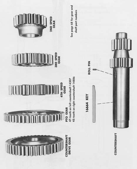
30 COUNTERSHAFT ASSEMBLY 28

31 REVERSE IDLER SHAFT AND GEAR ASSEMBLY GRAPH- ICS 29

32 REVERSE IDLER GEAR AS ASSEMBLED IN CASE 30

33 MAINSHAFT ASSEMBLY 31

34 TAILSHAFT ASSEMBLY 32

35 TAILSHAFT AND REAR BEARING COVER ASSEMBLY 33

36 SHIFTING BAR HOUSING ASSEMBLY 34
37 Inspection Before reassembling the transmission, the individual parts should be carefully checked to eliminate those damaged from previous service. This inspection procedure should be carefully followed to insure the maximum of wear life from the rebuilt unit. D. Thrust Washers 1. Check surfaces of all thrust washers. Washers scored or reduced in thickness should be replaced. The cost of a new part is generally a small fraction of the total cost of downtime and labor, should the use of a questionable part make additional repairs necessary before the next regularly scheduled overhaul. Recommended inspection procedures are set forth in the following checklist: A. Bearings 1. Wash all bearings in clean solvent. Check balls, rollers and races for pits and spalled areas. Replace bearings which are pitted or spalled. 2. Lubricate bearings which are not spalled or pitted and check for axial and radial clearances. Replace bearings with excessive clearances. 3. Check fits of bearings in case bores. If outer races turn freely in the bores, the case should be replaced. B. Gears 1. Check operating gear teeth for pitting on the tooth faces. Gears with pitted teeth should be replaced. 2. Check all engaging gear teeth. Gears with teeth worn, tapered or reduced in length from clashing in shifting should be replaced. 3. Check axial clearances of gears. Where excessive clearance is found, check gear snap ring, washer, spacer and gear hub for excessive wear. Maintain axial clearance of mainshaft forward speed gears,.005 minimum on reverse gear. C. Splines 1. Check splines on all shafts for wear. If sliding clutch gears, companion flange or clutch hubs have worn into the sides of the splines, the shafts in this condition should be replaced. E. Reverse Gear and Shaft 1. Check bearing sleeve for wear from action of roller bearings. F. Gray Iron Parts 1. Check all gray iron parts for cracks and breaks. Replace or repair parts found to be damaged. Heavy casting may be welded or brazed providing the cracks do not extend into bearing bores or bolting surfaces. G. Clutch Release Parts 1. Check clutch release parts. Replace yokes worn at cam surfaces and bearing carrier worn at contact pads. 2. Check pedal shafts. Replace those worn at bearing surfaces. H. Shifting Bar Housing Assembly 1. Check yokes and blocks for wear at pads and lever slot. Replace worn parts. 2. Check yokes for alignment. 3. Check yokes for excessive wear; replace worn yokes. 4. Check lockscrews in yokes and blocks. Tighten and rewire those found loose 35
38 Recommended torque ratings, location and thread sizes of capscrews and nuts are listed below. Capscrew length are given for reference purposes as a guide to installation at proper locations. TORQUE RATINGS Correct torque application is extremely important to assure long transmission life and dependable performance. Over-tightening or under-tightening can result in a loose installation and, in many instances, eventually causing damage to transmission gear, shafts or bearings. Do not torque capscrews dry. CAPSCREWS Location Qty. Thread Size and Length Torque Rating Foot-Pound P.T.O. Cover, Small Tailshaft Key Spacer Ring Tailshaft Key /8-16 x ¾ 5/16-24 x 5/8 5/16-24 x Reverse Idler Shaft Lock 2 5/16-18 x ¾ Poppet Spring Cover Front Bearing Cover Shifting Bar Housing Gear Shift Lever Housing Mainshaft Rear Bearing Cover Countershaft Rear Bearing Cover /8-16 x 1 3/8-16 x1-¼ 3/8-16 x1-¼ 3/8-16 x1-¼ 3/8-16 x1-¼ 3/8-16 x1-¼ P.T.O. Cover, Large 8 7/16-14 x 1-¼ Clutch Housing to Case 2 2 ½-13 x 1-¼ ½-13 x 3-¼ (70-75)* Countershaft Front Bearing Retainer 4 ½-20 x NUTS Clutch Housing to Case Drive Gear Tailshaft Front Bearing Companion Flange or Yoke / / / ½ ( )* Seat gaskets with shellac on part to be installed. Use new gaskets throughout when reassembling transmission. Gaskets are located on the following parts: P.T.O. Cover, Small P.T.O. Cover, Large Gear Shift Lever Housing Clutch Housing Front Bearing Cover Countershaft Rear Bearing Covers Shifting Bar Housing Mainshaft Rear Bearing Cover LOCATION OF GASKETS 37

39 PREVENTATIVE MAINTENANCE CHECK CHART 38
40 CHECKS WITHOUT PARTIAL DISASSEMBLY OF CHASSIS OR CAB PREVENTATIVE MAINTENANCE CHECK CHART 1. Clutch Housing Mounting a. Check all capscrews in bolt circle of clutch housing for looseness. 2. Clutch Pedal Shaft and Bores a. Pry upward on shaft to check wear. b. If excessive movement is found, remove clutch release mechanism and check bushings in bores and wear on shafts. 3. Clutch Release Bearing a. Remove hand hole cover and check radial and axial clearance in release bearing. b. Check relative position of thrust surface of release bearing with thrust sleeve on push type clutches. 4. Capscrews and Gaskets a. Check all capscrews, especially those on PTO covers and rear bearing covers for looseness which would cause oil leakage. b. Check PTO opening and rear bearing covers for oil leakage due to faulty gasket. 5. Gear Lubricant a. Change at specified service intervals. b. Use only gear oils as recommended (See Lubrication Section). 6. Filler and Drain Plugs 8. Gear Shift Lever Housing Assembly a. Remove the gear shift lever housing assembly from transmission. b. Check tension spring and washer for set and wear. c. Check the gear shift lever pivot pin and pivot pin slot for wear. d. Check bottom end of gear shift lever for wear and check slot of yokes and blocks in shift bar housing for wear at contact points with shift lever. CHECKS WITH DRIVE LINE DROPPED 9. Universal Joint Companion Flange Nut a. Check for tightness. Tighten to recommended torque. CHECKS WITH UNIVERSAL JOINT COMPANION FLANGE REMOVED 10. Splines on Output Shaft a. Check for wear from movement and chucking action of the universal join companion flange. 11. Mainshaft Rear Bearing Cover a. Check oil seal for wear. 12. Output Shaft a. Pry upward against output shaft to check radial clearance in mainshaft rear bearing. a. Remove filler plug and check level of lubricant at specified intervals. Tighten filler and drain plugs securely. 7. Gear Shift Lever a. Check for looseness and free play in housing. If lever is loose in housing, proceed with Check #8. 39

41 GENERAL PRECAUTIONS FOR REASSEMBLY IMPORTANT: Read this section before starting the detailed reassembly procedures. Make sure that interiors of case and housings are clean. It is important that dirt be kept out of transmission during reassembly. Dirt is abrasive and can damage polished surfaces of bearings and washers. Use certain precautions, as listed below, during reassembly. 1.GASKETS - Use new gaskets throughout the transmission as it is being rebuilt. Make sure all gaskets are installed, as omission of gasket can result in oil leakage or misalignment of bearing covers (See Location of Gaskets heading). 6.BEARINGS - Use of flangedend bearing drivers is recommended for the installation of bearings. These drivers apply equal force to both races of bearing, preventing damage to balls and races and maintaining correct bearing alignment with shaft and bore. If tubular or sleeve type driver is used, apply force only to inner race. 7. UNIVERSAL JOINT COMPANION FLANGE - Pull the companion flange tightly into place with the mainshaft nut, using ft. lbs. of torque. Make sure the speedometer gear is not used, a replacement 2. CAPSCREWS - To prevent oil leakage, use shellac on all capscrews. See torque rating chart for recommended torque. 3. ASSEMBLY - Refer to the assembly illustration, pages 27-34, as a guide to reassembly. 4. INITIAL LUBRICATION - Coat all thrust washers and splines of shafts with Lubriplate during installation to provide initial lubrication, preventing scoring and galling. 5. AXIAL CLEARANCES - Maintain the following axial clearances: spacer of the same width must be used. Failure to pull the yoke or flange tightly into place will permit the shaft to move axially with resultant damage to rear bearing. Mainshaft Forward Speed Gears Mainshaft Reverse Speed Gear Reverse Idler Gear Mainshaft
. 3.")
. 5.")
.")

42 DETAILED REASSEMBLY INSTRUCTIONS A. To Reassemble the Drive Gear Assembly 1. Install snap ring in ID of drive gear (See Illustration #55). 2. Install the drive gear on shaft, engaging internal splines of gear with teeth on shaft, snap ring of gear towards the front (See Illustration #56). 3. Install drive gear spacer on shaft and against gear (See Illustration #57). 4. Press the drive gear bearing on shaft, shield to the front (See Illustration #58). 5. Clean threads of drive gear and nut and apply grade AVV Loctite (See Illustration #59). 6. Install the bearing nut on shaft, left-hand thread, with ft. lbs of torque (See Illustration #60). NOTE: If torque wrench is not available, torque can be approximated by multiplying the pounds of pull time the length of wrench handle. For example: If there are 150 pounds of pull on a wrench with a two-foot handle, multiply 150 x 2, which equals 300 ft. lbs. of torque. Ordinary pull scales can be used to measure pounds of pull. #55 - Installing snap ring in ID of drive gear. #57 - Installing spacer on shaft. #56 - Installing drive gear on input shaft, engaging gear splines with shaft splines. #58 - Drive gear bearing installed on shaft. 41


43 REASSEMBLY #59 - Applying Loctite sealant to threads of drive gear nut. #62 - Drive gear teeth marked for timing, two adjacent teeth plus two adjacent teeth directly opposite. #60 - Installing drive gear bearing nut, left-hand thread. #63 - Installing the drive gear assembly through top of case. #61 - Peening nut into the two milled slots of shaft. #64 - Installing snap ring on drive gear bearing. 42


44 1. Clean threads of drive gear and nut and apply grade AVV Loctite (See Illustration #59). 2. Install the bearing nut on shaft, left-hand thread, with ft. lbs of torque (See Illustration #60). NOTE: If torque wrench is not available, torque can be approximated by multiplying the pounds of pull time the length of wrench handle. For example: If there are 150 pounds of pull on a wrench with a two-foot handle, multiply 150 x 2, which equals 300 ft. lbs. of torque. Ordinary pull scales can be used to measure pounds of pull. B. To Reassemble the Countershaft Assemblies NOTE: Except for the power take-off gears, the countershafts are identical. 1. Install roll pin in bore located in keyway of countershaft (See Illustration #66). 3. Peen the nut into the two milled slots of shaft (See Illustration #61). 4. IMPORTANT: Mark the drive gear for timing. Mark any two adjacent teeth on the drive gear, then mark two adjacent teeth which are directly opposite the first set marked (See Illustration #62). A. To Install the Drive Gear Assembly 1. Remove the snap ring from drive gear bearing. 2. Insert the drive shaft from inside case through front bore. Seat the drive gear bearing in case bore and move assembly forward until snap ring groove in bearing is exposed (See Illustration #63). #65 - Installing the drive gear bearing cover. 3. Install snap ring in bearing groove (See Illustration #64). 4. Seat bearing in case bore. 5. Install the drive gear bearing cover, aligning oil return slot in cover with oil return bore in case. Tighten capscrews securely (See Illustration #65). #66 - Installing roll pin in countershaft. 43


45 REASSEMBLY #67 - Installing keys in countershaft. #70 - Pressing the power take-off gear on countershaft. #68 - Pressing the 2nd speed gear on countershaft. #71 - Pressing the drive gear on countershaft. #69 - Pressing the 3rd speed gear on countershaft #72 - Marking timing tooth on countershaft drive gear. Tooth is aligned with keyway and is stamped with an O. 44
. 5.")
. Illustration #73 - Placing left countershaft into position in case.")
46 REASSEMBLY 2. Install the short key in countershaft, tapered end against roll pin. 3. Install the long key in keyway in countershaft (See Illustration #67). 4. Align keyway in gear with keys in shaft and press the 2nd speed gear on shaft, long hub towards front of shaft (See Illustration #68). 5. Press the 3rd speed gear on countershaft, long hub towards 2nd speed gear (See Illustration #69). 6. Press the 4th speed gear on countershaft. 7. Press the power take-off gear on countershaft, bullet nose teeth towards rear of shaft (See Illustration #70). Illustration #73 - Placing left countershaft into position in case. NOTE: The left countershaft assembly has a 47-tooth PTO gear; the right assembly has a 45-tooth gear. Mark each assembly as right and left. 8. Press the drive gear on countershaft (See Illustration #71). 9. IMPORTANT: Mark countershaft drive gears for timing. On the drive gear of each countershaft, mark tooth that is aligned with keyway in gear; this tooth will be stamped with an O (See Illustration #72). C. To Time and Install the Left Countershaft Assembly 1. Place the left countershaft assembly with the 47-foot PTO gear into position in case (See Illustration #73). Illustration #74 - Centering left countershaft in front bore with wood block. 2. Center front of left countershaft in bore (See Illustration #74). 45


47 REASSEMBLY #78 - Installing bearing retainer plate on front of left countershaft. #75 - Timing tooth on countershaft meshed with timing teeth on drive gear. #79 - Installing rear bearing cover. #76 - Installing rear bearing on left countershaft. #77 - Installing front bearing on left countershaft. #80 - Installing plug in reverse idler shaft. 46
. 5.")
. 2.")
48 REASSEMBLY 3. Mesh the marked tooth on countershaft drive gear with two teeth marked on the main drive gear (See Illustration #75). 4. Center countershaft in rear bore and install the rear bearing on shaft and into case bore. Bearing can be started by installing partially on shaft before seating in bore (See Illustration #76). 5. Install front bearing on countershaft and into case bore (See Illustration #77). E. To Place Right Countershaft in Position 1. Lower the countershaft assembly through top of case, small end through the rear countershaft bore in case (See Illustration #82). 2. Move countershaft forward and into correct position, aligning timing tooth on countershaft with those on main drive gear. Do not install bearings. 6. Install the bearing retainer plate on front of countershaft, tighten and wire capscrews securely (See Illustration #78). 7. Install the rear bearing cover, tighten capscrews securely (Illustration #79). D. To Install the Right Reverse Idler Gear 1. Install plug in oil channel in idler shaft (See Illustration #80). 2. Press needle bearing into bore of reverse gear idler gear. 3. Place inner race of bearing in gear. 4. Place a thrust washer on each side of gear, oil slots to gear. #81 - Threading the right reverse idler shaft through reverse idler gear and the two thrust washers. 5. Place the reverse gear and the two thrust washers into position in case. 6. Thread the idler shaft through bore in rear of case, washers and gear. Make sure slot in idler shaft is aligned with lockplate capscrew bore in case (See Illustration #81). 7. Install the lockplate in slot in idler shaft. Tighten capscrew securely. #82 - Placing the right countershaft into position in case. Do not install bearings. 47


49 REASSEMBLY #83 - Drawing showing correct dimensions for mainshaft quills. #86 - Installing reverse gear washer on shaft and inserting key through keyway and washer. #84 - Installing quill bearing snap ring. #85 - Installing snap ring in ID of mainshaft gear. #87 - Installing the 1st-Reverse sliding clutch gear on shaft. 48
 1.")
50 REASSEMBLE F. To Reassemble the Mainshaft Assembly NOTE: Mainshaft should have quills assembled, one in each end. In case it is necessary to install quills, exact dimensions must be held between end of shaft and end of quill (See Illustration #83) 1. Place the mainshaft in a vise, pilot end up, so that keyway in shaft is exposed for insertion of key. 2. Install quill bearing on front quill. Do not move quill. 3. Install bearing snap ring on quill (See Illustration #84). 4. Install snap rings in ID of all mainshaft gears except the reverse gear (See Illustration #85). 5. Install the reverse gear washer in the lowest radial groove in mainshaft, aligning keyway in washer with keyway in shaft. Flat side of washer is down. NOTE: Gear WASHERS are internally splined and contain a square keyway which locks washers to mainshaft. Gear SPACERS are externally splined to engage splines in gear hubs. There is one washer and one spacer for each gear. #88 - Installing the 1st speed gear washer, flat side up, engaging keyway with key. 6. Install the long key from the bottom in mainshaft keyway and through keyway in washer, snap ring groove in key to the rear and outside (See Illustration #86). NOTE: The long key is moved upward to engage each washer as it is placed on mainshaft. 7. Install the 1st-Reverse sliding clutching gear on mainshaft, aligning large keyway in gear with key in shaft (See Illustration #87). 8. Install the 1st speed gear washer, flat side up, in the third radial groove from top of shaft, aligning keyway in washer with keyway in shaft (See Illustration #88). 9. Move the long key up to engage the 1st speed gear washer. 49


51 REASSEMBLY #89 - Installing the 1st speed gear spacer, flat side to washer. #91 - Installing the 2nd speed gear. #90 - Installing the 1st speed gear on shaft and splines of spacer. #92 - Installing the 2nd speed gear spacer into hub of gear, flat side up. 50
 12.")
52 REASSEMBLY 10. Install the 1st speed gear spacer on shaft, flat side to washer (See Illustration #89). 11. Install the 1st speed gear, snap ring up, on shaft, engaging splines of gear with splines of spacer (See Illustration #90) 12. Install the 2nd speed gear, snap ring down, on shaft and against the 1st speed gear (See Illustration #91). 13. Install the 2nd speed gear spacer on shaft and into hub of gear, flat side up, engaging splines of gear with splines of spacer (See Illustration #92). 14. Install the 2nd speed gear washer, flat side against spacer, aligning keyway in washer with keyway in shaft (See Illustration #93). 15. Move key upward to engage the 2nd speed gear washer. 16. Install the 2nd-3rd speed sliding clutch gear on mainshaft, aligning large keyway in gear with key in shaft (See Illustration #94). #93 - Installing the 2nd speed gear washer, engaging keyway with key. #94 - Installing the 2nd-3rd speed sliding clutch on shaft. 51


53 REASSEMBLY #95 - Installing the 3rd speed gear washer, flat side up, engaging keyway with key. #97 - Installing the 3rd speed gear on shaft and splines of spacer. #96 - Installing the 3rd speed gear spacer, flat side next to washer. Illustration #98 - Installing the 4th speed gear on shaft. 52
. 20.")
. 23.")
54 REASSEMBLY 17. Install the 3rd speed gear washer, flat side up, on mainshaft, aligning keyway in washer in shaft (See Illustration #95). 18. Move the key upwards to engage the 3rd speed gear washer. Align snap ring slot at rear of key with snap ring groove in mainshaft. 19. Install the 3rd speed gear spacer, flat side against washer (See Illustration #96). 20. Install the 3rd speed gear on shaft, snap ring up, engaging gear splines with splines of spacer (See Illustration #97). 21. Install the 4th speed gear on shaft, snap ring down (See Illustration #98). 22. Install the 4th speed gear spacer, flat side up (See Illustration #99). 23. Install the 4th speed gear washer on shaft, flat side against spacer, aligning keyway in washer with keyway in shaft (See Illustration #100). 24. Make sure pin is installed in the short 4th speed gear mainshaft key. #99 - Installing the 4th speed gear spacer, flat side up. #100 - Installing the 4th speed gear washer on shaft and aligning keyway in washer with keyway in shaft. 53


55 REASSEMBLY #103 - Installing the reverse gear on mainshaft. #101 - Installing the short key in keyway in mainshaft to lock the 4th speed gear washer. #104 - Installing the reverse gear spacer on shaft. #105 - Installing key retaining snap ring on mainshaft. #102 - Installing the 4th-5th speed sliding clutch gear. #106 - The right countershaft moved towards case wall. 54
. 27.")
. 30.")
56 REASSEMBLY 25. Install the short key in keyway in mainshaft to lock the 4th speed gear washer in position (See Illustration #101). 26. Install the 4th-5th speed sliding clutch gear on shaft, aligning large keyway in gear with key in shaft (See Illustration #102). 27. Remove the assembly from vise and install the reverse gear on rear of shaft, snap ring groove in ID to the rear (See Illustration #103). 28. Move the reverse gear as far forward on shaft as possible, against the first speed gear. 29. Install the reverse gear spacer on shaft, flat side against washer (See Illustration #104). 30. Lock the long key in position by installing snap ring in mainshaft groove and key slot (See Illustration #105). #107 - Lowering mainshaft in position in case; mesh corresponding gears on left countershaft with those on mainshaft. G. To Install the Mainshaft Assembly 1. Move the right countershaft assembly as far as possible towards case wall (See Illustration #106). 2. With the reverse gear as far forward as possible, install the mainshaft into position in case, meshing corresponding gears on left countershaft with those on mainshaft (See Illustration #107). 3. Block under rear of mainshaft to exactly center shaft in rear bore. Front quill bearing should be seated in pocket of drive gear (See Illustration #108). #108 - Mainshaft assembly in correct position in case. 55


57 REASSEMBLY #109 right countershaft moved into position to mesh with gears of mainshaft. Timing tooth on drive gear must mesh with tining teeth on main drive gear. #113 Installing rear bearing cover on right countershaft. #110 Installing rear bearing on right countershaft. #114 Installing plug in left rererse idler gear shaft. #111 Installing front bearing on right countershaft. #112 Installing bearing retainer plate on front of right countershaft. #115 Place the two thust washers and reverse idler gear into position in case. 56

. 3. Install front bearing on countershaft and into case bore (See Illustration #111). 4.")
58 REASSEMBLY H. To Time Right Countershaft and Complete Installation 1. Center front of right countershaft in front bore with wood block and move the right countershaft into mesh with the mainshaft gears. At the same time engage timing tooth on countershaft drive gear with timing teeth on main drive gear. 2. Center countershaft in rear bore and install the rear bearing on shaft and in case bore. Bearing can be started by installing partially on shaft before seating in bore (See Illustration #110). 3. Install front bearing on countershaft and into case bore (See Illustration #111). 4. Install the bearing retainer plate on front of countershaft. Tighten and wire capscrews securely (See Illustration #112). 5. Install rear bearing cover on countershaft (See Illustration #113). #116 - Threading reverse idler shaft through reverse idler gear and the two thrust washers. I. To Install the Left Reverse Idler Gear 1. Install plug in oil channel in idler shaft (See Illustration #114). 2. Press needle bearing into bore of reverse idler gear. 3. Place inner race of bearing in gear. 4. Place a thrust washer on each side of gear, oil slots to gear (See Illustration #115). 5. Place the reverse gear and the two thrust washers into position in case. #117 - Installing lockplate in reverse idler shaft. 6. Thread the idler shaft through bore in rear of case, washers and gear. Make sure slot in idler shaft is aligned with lockplate capscrew bore in case (See Illustration #116). 7. Install the lockplate in slot in idler shaft. Tighten capscrew securely (See Illustration #117). 57


59 REASSEMBLY #118 - The mainshaft reverse gear moved to the rear to mesh with the two reverse idler gears. #121 - Installing nuts on case studs with ft.lbs of torque. #122 - Installing bolts in clutch housing with ft.lbs. of torque #119 - Installing snap ring in ID of mainshaft reverse gear. #120 - Installing clutch housing on front of transmission. Illustration #123 - Pressing bearing on tailshaft. 58
. 2.")
.")
. 4. Install the clutch release mechanism if transmission is so equipped. L. To Reassemble the Tailshaft Assembly 1.")
60 REASSEMBLY J. To Complete Installation of Mainshaft Assembly 1. Move the reverse gear to the rear on mainshaft as far as possible, meshing teeth of gear with teeth of the two reverse idler gears (See Illustration #118). 2. With mainshaft forward and reverse gear to the rear, seat the reverse gear spacer previously installed on shaft in hub of gear, and install the snap ring in ID of reverse gear (See Illustration #119). K. To Install Clutch Housing 1. Place clutch housing in position on the six studs in front case, piloting on drive gear cover (See Illustration #120). #124 - Applying Loctite to threads of bearing nut. 2. Install the six nuts with ft.lbs. of torque (See Illustration #121). 3. Install the four bolts in clutch housing with ft. lbs. of torque (See Illustration #122). 4. Install the clutch release mechanism if transmission is so equipped. L. To Reassemble the Tailshaft Assembly 1. Press the front bearing on tailshaft, snap ring to the rear (See Illustration #123). 2. Clean threads of tailshaft and bearing nut and apply grade AVV Loctite (See Illustration #124). #125 - Installing bearing nut, left hand thread, with ft.lbs. of torque. 3. Install the bearing nut on tailshaft with ft.lbs. of torque (See Illustration #125). #126 - Installing key-spacer ring on tailshaft. 59


61 REASSEMBLY #127 - Installing coupling gear on mainshaft, counterbore towards the front. #130 - Flat keys secured to spacer ring and properly wired. #128 - Installing tailshaft assembly over mainshaft and in case bore. #131 - Installing outer bearing on tailshaft. #129 - Installing flat keys in tailshaft to engage slot in mainshaft. #132 - Installing bearing washer on tailshaft. 60
. 2.")
 4.")
. N.")
62 REASSEMBLY M. To Install the Tailshaft Assembly 1. Install the coupling gear on splines of mainshaft with the counterbore towards the front and keyway aligned with key in shaft (See Illustration #127). 2. Install the tailshaft assembly over mainshaft, seating bearing in case bore. MAKE SURE SPLINES IN TAILSHAFT ENGAGE SPLINES OF COUPLING GEAR (See Illustration #128). 3. Install the flat keys in bores in tailshaft to engage slot in mainshaft (See Illustration #129) 4. Secure flat keys with 5/16 x 1 capscrews and tighten all capscrews in spacer ring evenly and securely. Install safety wire (See Illustration #130). #133 - Installing speedometer drive gear on tailshaft. 5. Install outer bearing on tailshaft, seating against shaft shoulder (See Illustration #131). N. To Reassemble and Install the Rear Bearing Cover Assembly 1. Install the tailshaft bearing washer on shaft and against bearing, chamfered ID to bearing (See Illustration #132). 2. Install the speedometer drive gear or replacement spacer on shaft and against washer (See Illustration #133). 3. Install speedometer bushing in rear bearing cover if required. #134 - Installing oil seal in rear bearing cover. 4. Install oil seal in rear bearing cover (See Illustration #134). 5. Install rear bearing cover evenly on tailshaft to seat tailshaft bearing in cover, aligning oil slot in cover with slot in case (See Illustration #135). #135 - Installing rear bearing cover on tailshaft. Install evenly to properly seat outer bearing. 61


63 REASSEMBLY #136 - Securing rear bearing cover to transmission case. #139 - Installing interlock ball in front boss. #137 - Installing companion flange nut with ft.lbs. of torque. #140 - Installing interlock pin in bore in neutral notch of 2nd-3rd speed shifting bar #138 - Installing the 1st-Reverse speed shift bar and shifting yoke and block. #141 - Installing interlock ball in front boss. 62


64 REASSEMBLY 6. Install attaching capscrews, tighten evenly and securely (See Illustration #136). O. To Install the Companion Flange or Yoke 1. Lock the mainshaft by engaging two speeds with the sliding clutch gears. 2. Install Flange or yoke on tailshaft splines and secure with tailshaft nut, using ft. lbs. of torque (See Illustration #137). P. To Reassemble the Shifting Bar Housing 1. Install the housing in a vise with the left side up. NOTE: Shift bars should be installed from the front with neutral and shift notches to the front. Keep bars in the neutral position when installed. 2. Install the long 1st-Reverse shift bar in lowest bore in housing, installing the shifting yoke and block on bar, long hub of each to the front (See Illustration #139). #142 - Installing the 4th-5th speed shifting bar and shifting yoke. 3. Install lockscrew in yoke and block, tighten and wire securely. 4. Install ¾ interlock ball in bore in front boss (See Illustration #139). 5. Install the 2nd-3rd speed shifting bar in center bore in housing and install shift yoke, long hub to the rear. At the same time install interlock pin bore in neutral notch of bar as notch enters front boss (See Illustration #140). 6. Install yoke lockscrew, tighten and wire securely. 7. Install ¾ interlock ball in bore in front boss (See Illustration #141). 8. Install the 4th-5th speed shifting bar in upper bore in housing installing shift yoke on bar, fork to the front (See Illustration #142). #143 - Shifting bar housing with yokes, blocks and bars correctly installed. 9. Install yoke lockscrew, tighten and wire securely (See Illustration #143). 10. Remove housing from vise. 63


65 REASSEMBLY #144 - Installing tension balls in bores on top of housing. #147 - Installing the shifting bar housing on transmission, fitting yokes in yoke slots of sliding gears. #145 - Installing the three tension springs in bores. #148 - Installing nut on gear shift lever pivot pin. #146 - Shifting bars in the neutral position. #149 - Installing the gear shift lever in housing. 64

66 REASSEMBLY 11. Install the three shift bar tension balls in bores in top of housing (See Illustration #144). 12. Install three tension springs in bores (See Illustration #145). 13. Install tension spring cover, tighten capscrews securely. Q. To Install the Shifting Bar Housing Assembly 1. Place the sliding clutch gears in transmission in the neutral position. 2. Make sure shifting bars in housing are in the neutral position (See Illustration #146). 3. Install the shifting bar housing on transmission, fitting yokes into corresponding yoke slots of sliding gears, tighten capscrews securely (See Illustration #147). R. To Reassemble and Install the Gear Shift Lever Housing Assembly #150 - Installing the tension spring washer in housing. 1. Install the pivot pin in bore in housing, thread end outward. 2. Install lockwasher and nut on pivot pin (See Illustration #148). 3. Mount the housing in a vise with the large bottom opening upwards. 4. Insert the gear shifts lever in housing, fitting slot in pivot ball of shift lever on pivot pin (See Illustration #149). 5. Install the tension spring washer in housing (See Illustration #150). 65

. 8.")
67 REASSEMBLY 6. Install the tension spring in housing, seating spring under lugs cast inside the housing (See Illustration #151). 7. Remove assembly from vise and install the rubber protector over the gear shift lever and against neck of housing. 9. Make sure the shifting notches in the shifting bar housing are aligned in the neutral position. 10. Install the gear shift lever housing, fitting lever into notches in block and yokes; tighten capscrews securely (See Illustration #152). 8. Install ball grip on shift lever #151 - Installing tension spring in housing, fitting spring under lugs cast inside the housing. #152 - Installing the gear shift lever housing on shifting bar housing. 66
Service Manual. Fuller Mechanical Transmissions TRSM0992 October 2007
 Service Manual Fuller Mechanical Transmissions TRSM0992 October 2007 Introduction Warnings and Precautions Before starting a vehicle always be seated in the driver s seat, place the transmission in neutral,
Service Manual. Fuller Medium Heavy Transmissions TRSM0226 October 2007
 Service Manual Fuller Medium Heavy Transmissions TRSM0226 October 2007 RT-906 SERIES Twin Countershaft ROADRANGER Transmissions 6 forward speeds - 2 reverse speeds Six forward speeds are obtained with
Service Manual. Fuller Heavy Duty Transmissions TRSM0250 October 2007
 Service Manual Fuller Heavy Duty Transmissions TRSM0250 October 2007 TABLE OF CONTENTS FOREWORD........................................ MODEL DESIGNATIONS AND SPECIFICATIONS.......... LUBRICATION......................................
Service Manual. Fuller Heavy Duty Transmissions TRSM0515 October 2007
 Service Manual Fuller Heavy Duty Transmissions TRSM0515 October 2007 TABLE OF CONTENTS Timing Description Operations Lubrication Preventive Maintenance Torque Recommendations Air System Precautions Disassembly
Transmission Overhaul Procedures-Bench Service
 How to Install the Auxiliary Countershaft Assembly Special Instructions To make auxiliary section assembly easier, you can make an auxiliary section fixture out of a 2" x 12" piece of wood. 3' 1' 3" 4.56"
Fuller Heavy Duty Transmissions TRSM0503 October 2007
 Service Manual Fuller Heavy Duty Transmissions TRSM0503 October 2007 RTX-12510 RTX-12515 RTXF-12510 RTXF-12515 Table of Contents Model Designations..............................3 Description....................................4
Service Manual. Fuller Heavy Duty Transmissions. Fuller Heavy Duty Transmissions. October 2007 TRSM0300. More time on the road
 Fuller Heavy Duty Transmissions More time on the road Service Manual Fuller Heavy Duty Transmissions TRSM0300 October 2007 RTO-11607L RTO-11607L RTO-11607LL RTO-11607LL RTOF-11607L RTOF-11607LL TABLE
Fuller Mid-Range Transmissions TRSM0160 October 2007
 Service Manual Fuller Mid-Range Transmissions TRSM0160 October 2007 FS-5106A FS-6206A Before starting a vehicle always be seated in the drivers seat, place the transmission in neutral, set the parking
Fuller Mid-Range Transmissions TRDR0100
 Driver Instructions Video Instruction Available Instructional videos are available for download at no charge at roadranger.com Videos are also available for purchase. To order, call 1-888-386-4636. Ask
Transmission Overhaul Procedures-Bench Service
 How to Assemble the Lower Reverse Idler Gear Assembly Special Instructions In 1996 Eaton changed the reverse idler system design. In the nut design, the reverse idler bearing was lubricated through a hole
MANUAL TRANS OVERHAUL - BORG-WARNER - T56 6-SPEED MANUAL TRANSMISSIONS Borg-Warner T56 (MM6) 6-Speed
 6-Speed") IDENTIFICATION MANUAL TRANS OVERHAUL - BORG-WARNER - T56 6-SPEED 1998 MANUAL TRANSMISSIONS Borg-Warner T56 (MM6) 6-Speed Transmission has 2 identification labels, located on lower left side of case. One
IDENTIFICATION MANUAL TRANS OVERHAUL - BORG-WARNER - T56 6-SPEED 1998 MANUAL TRANSMISSIONS Borg-Warner T56 (MM6) 6-Speed Transmission has 2 identification labels, located on lower left side of case. One
SECTION 5B MANUAL TRANSMISSION TABLE OF CONTENTS
 SECTION 5B MANUAL TRANSMISSION TABLE OF CONTENTS General Description and Operation... 5B-2 Shift Lever... 5B-2 Transmission Assembly... 5B-2 Specifications... 5B-3 Diagnostic Information and Procedures...
For the most current information, visit the Roadranger web site at
 Eaton Fuller Heavy Duty Transmissions 8 - Speed Direct Drivers Instructions TRDR-0310 March 2004 For the most current information, visit the Roadranger web site at www.roadranger.com Warnings Warnings
Fuller Automated Transmissions TRSM0020 October 2007
 Service Manual Fuller Automated Transmissions TRSM000 October 007 RT-09A-AT RT-09A-ATR RT-09A-ATS RT-09A-AT RT-409A-ATS RTO-09A-AT RTO-09A-ATS RTO-09B-AT RTO-09B-ATE RTO-09B-ATR RTO-09B-ATS RTO-09A-AT
Telephone (925) Fax (925) Lawrence Drive,Livermore, California
 Fax (925) Lawrence Drive,Livermore, California") Telephone (925) 454-9500 Fax (925) 454-9501 151 Lawrence Drive,Livermore, California 94551 www.fabcoautomotive.com Fabco Automotive Corporation Transfer Case Service Manual Model TC-33 625 320 Copyright
Telephone (925) 454-9500 Fax (925) 454-9501 151 Lawrence Drive,Livermore, California 94551 www.fabcoautomotive.com Fabco Automotive Corporation Transfer Case Service Manual Model TC-33 625 320 Copyright
Service Manual. Fuller Heavy Duty Transmissions TRSM0880 October 2007
 Service Manual Fuller Heavy Duty Transmissions TRSM0880 October 2007 For parts or service call us Pro Gear & Transmission, Inc. 1 (877) 776-4600 (407) 872-1901 parts@eprogear.com 906 W. Gore St. Orlando,
Fuller Heavy Duty Transmissions TRSM0660 October 2007
 Service Manual Fuller Heavy Duty Transmissions TRSM0660 October 2007 RTLO-14613B RTLOF-14613B TABLE OF CONTENTS FOREWORD............. MODEL DESIGNATIONS AND LUBRICATION............ OPERATION.............
Service Manual. Fuller Mid Range Transmissions TRSM0195 October 2007
 Service Manual Fuller Mid Range Transmissions TRSM0195 October 2007 Caution - Before towing the vehicle, be sure to lift the rear wheels off the ground or disconnect the driveline to avoid damage to the
Telephone (925) Fax (925) Lawrence Drive, Livermore, CA
 Fax (925) Lawrence Drive, Livermore, CA") Telephone (925) 454-9500 Fax (925) 454-9501 151 Lawrence Drive, Livermore, CA 94551 www.fabcoautomotive.com SERVICE MANUAL TC-140 TRANSFER CASE TWO SPEED, TC-141 SINGLE SPEED Table of Contents I. TC-140
Telephone (925) 454-9500 Fax (925) 454-9501 151 Lawrence Drive, Livermore, CA 94551 www.fabcoautomotive.com SERVICE MANUAL TC-140 TRANSFER CASE TWO SPEED, TC-141 SINGLE SPEED Table of Contents I. TC-140
Eaton Fuller Heavy Duty Transmissions
 Eaton Fuller Heavy Duty Transmissions 13 Speed Models Driver Instructions TRDR-0630 May 2004 For the most current information, visit the Roadranger web site at www.roadranger.com General Information Warnings
Service Manual. Fuller Heavy Duty Transmissions
 Fuller Heavy Duty Transmissions More time on the road Service Manual Fuller Heavy Duty Transmissions TRSM0430 July 2010 RT-8608L RTF-8608L RTO-11608LL RTO-14608LL RTOF-11608LL RTOF-14608LL RTX-11608LL
MANUAL TRANSAXLE Return to Main Table of Contents
 MANUAL TRANSAXLE Return to Main Table of Contents GENERAL... 2 MANUAL TRANSAXLE CONTROL... 12 SHIFT LEVER ASSEMBLY... 14 MANUAL TRANSAXLE... 15 MANUAL TRANSAXLE ASSEMBLY... 17 FIFTH SPEED SYNCHRONIZER
MANUAL TRANSMISSION MUA 5C (4X2, 4X4) AND TREMEC T5R(4X2)
 AND TREMEC T5R(4X2)") MANUAL TRANSMISSION 7B 1 RODEO TRANSMISSION MANUAL TRANSMISSION MUA 5C (4X2, 4X4) AND TREMEC T5R(4X2) CONTENTS Service Precaution...................... 7B 2 General Description..................... 7B
MANUAL TRANSMISSION 7B 1 RODEO TRANSMISSION MANUAL TRANSMISSION MUA 5C (4X2, 4X4) AND TREMEC T5R(4X2) CONTENTS Service Precaution...................... 7B 2 General Description..................... 7B
Service Manual. Fuller Mid Range Transmissions TRSM0197 October 2007
 Service Manual Fuller Mid Range Transmissions TRSM0197 October 2007 Caution - Before towing the vehicle, be sure to lift the rear wheels off the ground or disconnect the driveline to avoid damage to the
Service Manual. Fuller Mid Range Transmissions TRSM0194 October 2007
 Service Manual Fuller Mid Range Transmissions TRSM0194 October 2007 Caution - Before towing the vehicle, be sure to lift the rear wheels off the ground or disconnect the driveline to avoid damage to the
TC20 Chain Driven Power Take-Off Overhaul Instructions
 TC20 Chain Driven Power Take-Off Overhaul Instructions Table of Contents Section Page Introduction 4 Ordering Repair Parts 4 General Information 5 Special Tools 6 Disassembly See Page 2 Reassembly See
SUZUKI SQ 416/420/625 M.Y TRANSMISSION SERVICE MANUAL - MANUAL - AUTOMATIC - TRANSFER - DIFFERENTIALS
 SUZUKI SQ 416/420/625 M.Y 1998-2005 TRANSMISSION SERVICE MANUAL - MANUAL - AUTOMATIC - TRANSFER - DIFFERENTIALS WARNING/CAUTION/NOTE IMPORTANT Please read this manual and follow its instructions carefully.
Parts List PL_TR-TO-10_0714
 Torque Transfer Solutions TR-TO-10 Series 10-Speed Twin Counter Shaft Manual Transmission Parts List PL_TR-TO-10_0714 14700 Helm Ct. Plymouth, MI 48170 U.S.A. (800) 401-9866 www.tremec.com Copyright 2014
SPECIAL TOOLS Dodge Pickup 5.9L Eng R3500. Fig 1: Identifying Remover C-3985-B (Special Tool) 9/6/13 Printer Friendly View
 9/6/13 Printer Friendly View") Procedures 2003 Dodge Pickup 5.9L Eng R3500 manual transmission SPECIAL TOOLS Fig 1: Identifying Remover C-3985-B (Special Tool) www2.prodemand.com/print/index?content=tabs&module=true&tab=true&terms=true&ymms=false&classname=
Procedures 2003 Dodge Pickup 5.9L Eng R3500 manual transmission SPECIAL TOOLS Fig 1: Identifying Remover C-3985-B (Special Tool) www2.prodemand.com/print/index?content=tabs&module=true&tab=true&terms=true&ymms=false&classname=
Eaton Fuller Advantage Heavy-Duty Manual Transmissions TRSM0970 EN-US
 Service Manual Eaton Fuller Advantage Heavy-Duty Manual Transmissions TRSM0970 EN-US January 2016 FA(F)-9810B FA(F)-11810B FA(F)-12810B FA(F)-13810B FA(F)-14810B FA(F)-15810B FAO(F)-11810C FAO(F)-12810C
 Page 1 of 15 Transmission, Model S5-42 ZF Model S5-42 ZF Disassembly NOTE: For 4x4 and F-Super Duty vehicles, skip to Step 5. 1. Attach the transmission to the Bench Mounted Holding Fixture T57L-500-B
2001 Dodge RAM 3500 PICKUP
 1 of 76 9/14/2012 7:02 PM 2001 Dodge RAM 3500 PICKUP Submodel: Engine Type: L6 Liters: 5.9 Fuel Delivery: FI Fuel: DIESEL Subarticles MANUAL- NV3500 - DISASSEMBLY MANUAL- NV3500 - DISASSEMBLY MANUAL -
Fuller Heavy-Duty Transmissions TRSM1500 EN-US May 2017
 Service Manual Fuller Heavy-Duty Transmissions TRSM1500 EN-US May 2017 RT-8908LL RTO-11707LL RTO-11708LL RTOF-11707LL RTOF-11708LL RTOF-14708LL RTX-11708LL RTX-14708LL RTXF-11708LL RTXF-14708LL RTO-11707DLL
Installation Instructions for the Tera low range Dana 20 (LOW20)
") Installation Instructions for the Tera low range Dana 20 (LOW20) Tera Manufacturing, Inc. 5251 South Commerce Dr. Murray, Utah 84107 Phone/801.288.2585 Fax/801.288.2571 www.teraflex.biz Attention: Verify
Installation Instructions for the Tera low range Dana 20 (LOW20) Tera Manufacturing, Inc. 5251 South Commerce Dr. Murray, Utah 84107 Phone/801.288.2585 Fax/801.288.2571 www.teraflex.biz Attention: Verify
TRANSMISSION 6.7 GENERAL HOME. See Figure The transmission is a five-speed constantmesh type housed in an extension of the crankcase.
 TRANSMISSION 6.7 GENERAL See Figure 6-45. The transmission is a five-speed constantmesh type housed in an extension of the crankcase. Mainshaft Neutral Mainshaft st Gear b06x6x Countershaft 4 Out 5 Countershaft
TRANSMISSION AND TRANSFER CASE
 DR TRANSMISSION AND TRANSFER CASE 21-1 TRANSMISSION AND TRANSFER CASE TABLE OF CONTENTS page MANUAL TRANSMISSION- G56- SERVICE INFORMATION...1 MANUAL TRANSMISSION- GETRAG 238- SERVICEINFORMATION...69 MANUAL
TRANSMISSION AND TRANSFER CASE
 XJ TRANSMISSION AND TRANSFER CASE 21-1 TRANSMISSION AND TRANSFER CASE TABLE OF CONTENTS page AX5 MANUAL TRANSMISSION... 1 NV3550 MANUAL TRANSMISSION... 42 AUTOMATIC TRANSMISSION 30RH... 88 page AW 4 AUTOMATIC
1988 Chevrolet Pickup V SUSPENSION - FRONT (4WD)' 'Front Suspension - "V" Series 1988 SUSPENSION - FRONT (4WD) Front Suspension - "V" Series
' 'Front Suspension - V Series 1988 SUSPENSION - FRONT (4WD) Front Suspension - V Series") 1988 SUSPENSION - FRONT (4WD) Front Suspension - "V" Series DESCRIPTION NOTE: Vehicle serial numbers used in this article has been abbreviated for common reference to Chevrolet and GMC models. Chevrolet
1988 SUSPENSION - FRONT (4WD) Front Suspension - "V" Series DESCRIPTION NOTE: Vehicle serial numbers used in this article has been abbreviated for common reference to Chevrolet and GMC models. Chevrolet
1984 Dodge W250 PICKUP
 1984 Dodge W250 PICKUP Submodel: Engine Type: V8 Liters: 5.2 Fuel Delivery: CARB Fuel: GAS Dana 44 MODELS THROUGH 1984 2. Raise and safely support the vehicle, then remove the wheel hub and bearings as
MANUAL TRANSMISSION SECTION MT CONTENTS TRANSMISSION/TRANSAXLE MT-1 SERVICE INFORMATION POSITION SWITCH...13 Checking...13
 TRANSMISSION/TRANSAXLE SECTION MT A B MANUAL TRANSMISSION MT D CONTENTS E SERVICE INFORMATION... 2 PRECAUTIONS... 2 Service Notice or Precaution...2 PREPARATION... 3 Special Service Tool...3 Commercial
DISASSEMBLY. Transmission. 2. Remove the 4 clutch housing bolts. Separate the clutch housing from the transmission.
 308-03A-1 DISASSEMBLY Transmission 308-03A-1 Special Tool(s) Puller, Bearing 205-D064 (D84L-1123-A) or equivalent Remover/Installer, Front Wheel Hub 204-069 (T81P-1104-C) 2. Remove the 4 clutch housing
Maintenance Instructions
 General Note These instructions contain information common to more than one model of Bevel Gear Drive. To simplify reading, similar models have been grouped as follows: GROUP 1 Models 11, 0, 1,, (illustrated),,
4.2 WATER PUMP (GEAR CASE MOUNTED AND LATER) (GCM)
 (GCM)") SERIES 60 SERVICE MANUAL 4.2 WATER PUMP (GEAR CASE MOUNTED - 1991 AND LATER) (GCM) The centrifugal-type water pump circulates the engine coolant through the cooling system. The pump is mounted on the rear
SERIES 60 SERVICE MANUAL 4.2 WATER PUMP (GEAR CASE MOUNTED - 1991 AND LATER) (GCM) The centrifugal-type water pump circulates the engine coolant through the cooling system. The pump is mounted on the rear
FSO Transmission. Service Manual. Eaton Fuller Light Duty Transmissions. 3rd Ed. 03/10
 FSO-4505 Service Manual Transmission Eaton Fuller Light Duty Transmissions 3rd Ed. 03/10 General Information 1 Input Shaft Bearing Cover 2 Gear Shift Lever Housing 3 Main Section 4 Shifting System 5 Rear
1992 Clutch. Eclipse, Expo/Expo LRV, Galant, Mirage, Precis, 3000GT
 Article Text ARTICLE BEGINNING 1992 Clutch Eclipse, Expo/Expo LRV, Galant, Mirage, Precis, 3000GT DESCRIPTION All clutches are single disc type. Pressure plate assembly uses a diaphragm spring to engage
DRIVE AXLE Volvo 960 DESCRIPTION & OPERATION AXLE IDENTIFICATION DRIVE AXLES Volvo Differentials & Axle Shafts
 DRIVE AXLE 1994 Volvo 960 1994 DRIVE AXLES Volvo Differentials & Axle Shafts 960 DESCRIPTION & OPERATION All 960 station wagon models use type 1041 rear axle assembly. All 960 4-door models use type 1045
UltraShift PLUS Automated Transmissions TRSM0940 EN-US
 Service Manual UltraShift PLUS Automated Transmissions TRSM0940 EN-US April 2016 UltraShift PLUS Linehaul Active Shifting (LAS) UltraShift PLUS Vocational Active Shifting (VAS) UltraShift PLUS Multipurpose
TRANSMISSION AND TRANSFER CASE
 TJ TRANSMISSION AND TRANSFER CASE 21-1 TRANSMISSION AND TRANSFER CASE TABLE OF CONTENTS page MANUAL TRANSMISSION - NSG370...1 AUTOMATIC TRANSMISSION - 42RLE...37 page TRANSFER CASE - NV231...165 TRANSFER
TRANSMISSION 6.7 GENERAL HOME. See Figure The transmission is a five-speed constantmesh type housed in an extension of the crankcase.
 TRANSMISSION 6.7 GENERAL See Figure 6-46. The transmission is a five-speed constantmesh type housed in an extension of the crankcase. b06x6x Neutral st Gear Mainshaft Mainshaft 4 5 4 5 Countershaft Out
TSM54/52 MANUAL TRANSMISSION
 3B-1 SECTION 00 3B TSM54/52 MANUAL TRANSMISSION Table of Contents GENERAL INFORMATION... 3B-3 Overview... 3B-3 Specifications... 3B-4 System components... 3B-5 Shifting mechanism... 3B-17 Diagnostic information
3.2 DRIVE TORQUE HUB. Roll, Leak and Brake Testing SECTION 3 - CHASSIS & TURNTABLE. 3-2 JLG Lift
 3.2 DRIVE TORQUE HUB Roll, Leak and Brake Testing 10 LUG PATTERN Torque-Hub units should always be roll and leak tested before disassembly and after assembly to make sure that the unit's gears, bearings
Maintenance Information
 80234313 Edition 1 June 2006 Air Grinder, Die Grinder, Sander and Belt Sander Series G1 (Angle) Maintenance Information Save These Instructions WARNING Always wear eye protection when operating or performing
1989 Jeep Cherokee. STEERING COLUMN' '1989 STEERING Jeep Steering Columns STEERING COLUMN STEERING Jeep Steering Columns
 STEERING COLUMN 1989 STEERING Jeep Steering Columns DESCRIPTION All models use collapsible steering columns. All columns have integral ignition switch and locking device. Optional tilt wheel is available
Fuller Heavy Duty Transmissions. More time on the road. Service Manual. Fuller Heavy Duty Transmissions TRSM0917
 Fuller Heavy Duty Transmissions More time on the road Service Manual Fuller Heavy Duty Transmissions TRSM0917 October 2007 Table of Contents Applications Why Oil Cooling...................... 1 Why Operating
Maintenance Information
 80234313 Edition 2 May 2014 Air Grinder, Die Grinder, Sander and Belt Sander Series G1 (Angle) Maintenance Information Save These Instructions Product Safety Information WARNING Failure to observe the
CHAPTER 7 TRANSMISSION (MFO6S)
") 1 page INDEX1 Model SG1J (MF06S) TRANSMISSION 7-1 7-142E-07 CHAPTER 7 TRANSMISSION (MFO6S) Model SG1J 1 Models FE, FF and SG2J 1 Model FD 7 TROUBLESHOOTING...7-2 SPECIAL TOOLS...7-5 REMOVAL...7-7 GEAR
1 page INDEX1 Model SG1J (MF06S) TRANSMISSION 7-1 7-142E-07 CHAPTER 7 TRANSMISSION (MFO6S) Model SG1J 1 Models FE, FF and SG2J 1 Model FD 7 TROUBLESHOOTING...7-2 SPECIAL TOOLS...7-5 REMOVAL...7-7 GEAR
Hudson-Essex. Service Manual Supplement. Hudson Cars 750,001 up
 1 9 2 6 Hudson-Essex Service Manual 1927 Supplement Hudson Cars 750,001 up Hudson Rear Axle (Cars numbered 750,001 and upward) Brakes (Cars numbered 750,001 and upward) See page 18 Transmission Group
Valtek Auxiliary Handwheels and Limit Stops
 Valtek Auxiliary s and Limit Stops Table of Contents Page 1 General information 2 Installation 2 Side-mounted handwheels, size 25 and 50 (linear actuators) 3 Side-mounted handwheels, size 100 and 200 (linear
1994 Mitsubishi Eclipse GS
 APPLICATIONS CHRYSLER MOTORS MANUAL TRANS OVERHAUL - MITSUBISHI W5M & W6M SERIES MANUAL TRANSMISSIONS Mitsubishi W5M31, TRANSMISSION APPLICATIONS (CHRYSLER MOTORS) Vehicle Application Transmission Model
MANUAL TRANSMISSIONS Mitsubishi F4M20, F5M20, F5M30 & KM200 Series TRANSMISSION APPLICATION
 Article Text ARTICLE BEGINNING MANUAL TRANSMISSIONS Mitsubishi F4M20, F5M20, F5M30 & KM200 Series APPLICATION TRANSMISSION APPLICATION Vehicle Application Transmission Model Chrysler Motors (2WD) 4-Speed
This file is available for free download at
 This file is available for free download at http://www.iluvmyrx7.com This file is fully text-searchable select Edit and Find and type in what you re looking for. This file is intended more for online viewing
SPICER. WEATHERLYINDEX084 T21 O-ES70-5 October 1993 ES70-5 Series Main Transmission
 SPICER WEATHERLYINDEX084 T2 O-ES70-5 October 993 ES70-5 Series Main Transmission ES70-5 Series Main Transmission For parts or service call us Pro Gear & Transmission, Inc. (877) 776-4600 (407) 872-90 parts@eprogear.com
INSTRUCTIONS FOR OVERHAUL OF RAMEY RE SERIES WINCH
 INSTRUCTIONS FOR OVERHAUL OF RAMEY RE 12000 SERIES WINCH DISASSEMBLY 1. Drain oil from gear housing by removing plug # from bottom of gear housing. Remove relief fitting # and reducer # from top of gear
This file is available for free download at
 This file is available for free download at http://www.iluvmyrx7.com This file is fully text-searchable select Edit and Find and type in what you re looking for. This file is intended more for online viewing
1. General Description
 1. General Description A: SPECIFICATIONS 1. Type Transmission gear ratio Front reduction gear Rear reduction gear 2. TRANSMISSION GEAR OIL Recommended oil Final Transfer 5-forward speeds with synchromesh
REMOVAL TF REMOVE TRANSFER INDICATOR SWITCH (a) Remove the switches and gaskets. HINT: Indicator switch:
 Remove the switches and gaskets. HINT: Indicator switch:") 20 NO. 1 NO. 2 F043499 REMOVAL 1. DISCONNECT CABLE FROM NEGATIVE BATTERY TERMINAL CAUTION: Wait at least 90 seconds after disconnecting the cable from the negative (-) battery terminal to prevent airbag
20 NO. 1 NO. 2 F043499 REMOVAL 1. DISCONNECT CABLE FROM NEGATIVE BATTERY TERMINAL CAUTION: Wait at least 90 seconds after disconnecting the cable from the negative (-) battery terminal to prevent airbag
SISU DP-330 DRIVE GEAR. Maintenance Manual
 SISU DP-330 DRIVE GEAR Maintenance Manual Sisu Axles, Inc. Autotehtaantie 1 PO Box 189 Fin-13101 Hameenlinna Finland Phone +358 204 55 2999 Fax +358 204 55 2900 DP330DG.PDF (3/2007) TABLE OF CONTENTS
Maintenance Information
 16575243 Edition 2 October 2013 Air Screwdrivers 1R Series Maintenance Information Save These Instructions Product Safety Information WARNING Failure to observe the following warnings, and to avoid these
1. General Description
 1. General Description A: SPECIFICATION 1. MANUAL TRANSMISSION AND FRONT DIFFERENTIAL Type Transmission gear ratio Front reduction gear Rear reduction gear Front differential Center differential Final
Amarillo PUMP DRIVES (250 HP THROUGH 350 HP) INSTRUCTIONS FOR REPAIRING MODELS 250, 300, and 350
 INSTRUCTIONS FOR REPAIRING MODELS 250, 300, and 350") Amarillo PUMP DRIVES (250 HP THROUGH 350 HP) INSTRUCTIONS FOR REPAIRING MODELS 250, 300, and 350 Amarillo Right Angle Pump Drives, if properly installed and maintained, should provide years of service
Amarillo PUMP DRIVES (250 HP THROUGH 350 HP) INSTRUCTIONS FOR REPAIRING MODELS 250, 300, and 350 Amarillo Right Angle Pump Drives, if properly installed and maintained, should provide years of service
Manual Transmission (M2S5,M3S5) General Troubleshooting... MTA - 2 Specification... MTA - 9
 General Troubleshooting... MTA - 2 Specification... MTA - 9") Manual Transmission (M2S5,M3S5) General Troubleshooting... MTA - 2 Specification... MTA - 9 Manual Transmission Description and Operation... MTA - 13 Components... MTA - 19 Inspection... MTA - 20 Removal...
Manual Transmission (M2S5,M3S5) General Troubleshooting... MTA - 2 Specification... MTA - 9 Manual Transmission Description and Operation... MTA - 13 Components... MTA - 19 Inspection... MTA - 20 Removal...
2001 F-650/750 Workshop Manual
 26. Pack the reverse idler gear bearings with lubricant. Use Moly number 2 lubricant or equivalent. 27. Install the following: 1. Assemble the reverse idler gear and bearings onto the idler shaft. 2. Position
Maintenance Information
 04581245 Edition 2 May 2014 Air Grinder, Die Grinder and Sander Series G2 (Angle) Maintenance Information Save These Instructions Product Safety Information WARNING Failure to observe the following warnings,
REMOVAL & INSTALLATION
 REMOVAL & INSTALLATION AXLE SHAFTS & BEARINGS Removal CAUTION: Failure to turn off air suspension power before raising vehicle may result in unexpected inflation or deflation of air springs. DO NOT reconnect
TECHNICAL SERVICE MANUAL
 Electronic copies of the most current TSM issue can be found on the Viking Pump website at www.vikingpump.com TECHNICAL SERVICE MANUAL HEAVY-DUTY Stainless steel BRACKET MOUNTED PUMPS SERIES 127 AND 4127
INSTRUCTIONS. Disassembly. Shifter Cam Assembly. Shifter Forks
 INSTRUCTIONS Disassembly To protect against accidental start-up of vehicle, always disconnect the negative battery cable before working on the motorcycle. Failure to disconnect the battery cable could
DISASSEMBLY AND ASSEMBLY
 205-03-1 Front Drive Axle/Differential Ford 8.8-Inch Ring Gear 205-03-1 DISASSEMBLY AND ASSEMBLY Axle Front Drive Special Tool(s) 2-Jaw Puller 205-D072 (D97L-4221-A) Special Tool(s) Carrier Bearing Replacer
Maintenance Information
 45528270 Edition 1 June 2007 Barring Motor T480 Series Maintenance Information Save These Instructions WARNING Always wear eye protection when operating or performing maintenance on this Barring Motor.
Illustrated Parts List
 More time on the road Illustrated s List FS-5005A November 2012 Contents How To Use The Illustrated s List... CASE... 4 COUNTERSHAFT ASSY... 8 INPUT SHAFT... 10 KITS & ASSEMBLIES... 11 LEVER ASSY... 12
70001 and Clutch Rebuild Instructions
 70001 and 70010 Clutch Rebuild Instructions Brinn, Incorporated 1615 Tech Drive Bay City, MI 48706 Telephone 989.686.8920 Fax 989.686.6520 www.brinninc.com Notice Use these instructions if you only want
TRANSMISSION AND TRANSFER CASE
 TRANSMISSION AND TRANSFER CASE 21-1 TRANSMISSION AND TRANSFER CASE CONTENTS page page AUTOMATIC TRANSMISSION-30/32RH...... 71 MANUAL TRANSMISSION-AX5............. 1 MANUAL TRANSMISSION-AX15...........
Maintenance Information
 16575128 Edition 2 May 2014 Air Grinder, Sander or Polisher 77A Series Maintenance Information Save These Instructions Product Safety Information Failure to observe the following warnings, and to avoid
 a. SCOPE. g. : RA PD 28742 TM 9;1803B 2. MWO AND MAJOR UNIT ASSEMBLY REPLACEMENT RECORD. a. Description. b. _Instructions for Use. Early Modifications. CHAPTER 2 Section I 3. POWER TRAIN DESCRIPTION. a.
Telephone (925) Fax (925) Lawrence Drive, Livermore, CA
 Fax (925) Lawrence Drive, Livermore, CA") Telephone (925) 454-9500 Fax (925) 454-9501 151 Lawrence Drive, Livermore, CA 94551 www.fabcoautomotive.com Fabco Automotive Corp. TC-35 TRANSFER CASE Service Manual TABLE OF CONTENTS Title Page with Index
Telephone (925) 454-9500 Fax (925) 454-9501 151 Lawrence Drive, Livermore, CA 94551 www.fabcoautomotive.com Fabco Automotive Corp. TC-35 TRANSFER CASE Service Manual TABLE OF CONTENTS Title Page with Index
WD DODGE SUSPENSION LIFT KIT P/N
 4/03/03 94-01 4WD DODGE 1500 3 SUSPENSION LIFT KIT P/N 10-46094 NOTE: Each lift kit, and options to lift kits, are packaged separately. Therefore installation procedures are covered in separate instructions.
Service Manual. Example Part Number. Motor Supplier. Motor Number. Model. Bail Boss. Ratio. Shaft
 Service Manual 50 Series Digger models Example Part Number 50 05 f 54 Model Ratio Shaft Bail Boss Motor Supplier Motor Number This service manual is effective: S/N: 58670 to current date: 9-003 to CURRENT
Service Manual. Example Part Number. Motor Supplier. Motor Number. Ratio. Bail Boss. Input. Model. Shaft. Cover
 Service Manual 0 Series Digger models Example Part Number 0 7 f 0 C 7 Model Ratio Shaft Bail Boss Motor Supplier Motor Number Cover Input This service manual is effective: S/N: 0000 to current date: 0
CHASSIS CONTENTS EXTERIOR PARTS 6-1 FRONT WHEEL 6-2 FRONT BRAKE 6-6 HANDLEBARS 6-12 REAR WHEEL 6-30 REAR BRAKE 6-34 REAR SHOCK ABSORBER 6-36
 CHASSIS CONTENTS EXTERIOR PARTS 6-1 FRONT WHEEL 6-2 FRONT BRAKE 6-6 HANDLEBARS 6-12 FRONT FORK ( ) 6-14 FRONT FORK ( ) 6-20 STEERING 6-27 REAR WHEEL 6-30 REAR BRAKE 6-34 REAR SHOCK ABSORBER 6-36 6 SWING
DRIVE AXLE Nissan 240SX DESCRIPTION & OPERATION AXLE RATIO & IDENTIFICATION AXLE SHAFT & BEARING R & I DRIVE SHAFT R & I
 DRIVE AXLE 1990 Nissan 240SX 1990 DRIVE AXLES Rear Axle - R200 240SX, 300ZX DESCRIPTION & OPERATION The axle assembly is a hypoid type gear with integral carrier housing. The pinion bearing preload adjustment
Illustrated Parts List
 More time on the road Illustrated s List FS-4205B November 2012 Contents How To Use The Illustrated s List... CASE... 4 COUNTERSHAFT ASSY... 8 INPUT SHAFT... 9 KITS & ASSEMBLIES... 11 LEVER ASSY... 1 MAINSHAFT
Service Manual. Eaton Transmissions. TRSM0509 May 2010 ES ES ESO ESO 12209
 Service Manual Eaton Transmissions TRSM0509 May 2010 ES 11109 ES 11209 ESO 12109 ESO 12209 Table of Contents Introduction Warnings and Precautions...1 Purpose and Scope of Manual...2 How to use this Manual...2
TECHNICAL SERVICE MANUAL
 TECHNICAL SERVICE MANUAL HEAVY-DUTY bracket mounted PUMPS SERIES 4193 AND 493 SIZES GG - AL SECTION TSM 154 PAGE 1 of 10 ISSUE C CONTENTS Introduction....................... 1 Special Information...................
MANUAL TRANSAXLE SECTIONMT CONTENTS IDX. Shift Control Components...34
 MANUAL TRANSAXLE SECTIONMT GI MA EM LC EC CONTENTS FE PREPARATION...3 Special Service Tools...3 Commercial Service Tools...5 NOISE, VIBRATION AND HARSHNESS (NVH) TROUBLESHOOTING...6 NVH Troubleshooting
TRANSFER CASE Mitsubishi Montero APPLICATION DESCRIPTION TESTING 4WD INDICATOR CONTROL UNIT (MONTERO) DETECTION SWITCH
 DETECTION SWITCH") TRANSFER CASE 1993 Mitsubishi Montero 1991-94 TRANSFER CASES Mitsubishi Dodge; Ram-50 Mitsubishi; Pickup, Montero APPLICATION TRANSFER CASE APPLICATIONS TABLE Application (1) Transmission Model Dodge 1991-93
TRANSFER CASE 1993 Mitsubishi Montero 1991-94 TRANSFER CASES Mitsubishi Dodge; Ram-50 Mitsubishi; Pickup, Montero APPLICATION TRANSFER CASE APPLICATIONS TABLE Application (1) Transmission Model Dodge 1991-93
AUTOMATIC TRANSMISSIONS Mitsubishi F3A20 Series TRANSMISSION APPLICATION TABLE
 Article Text ARTICLE BEGINNING AUTOMATIC TRANSMISSIONS Mitsubishi F3A20 Series APPLICATION TRANSMISSION APPLICATION TABLE Vehicle Application Transmission Model Colt 3-Speed (1990-94)... F3A21 Colt Vista
CLUTCH CONTENTS SERVICE DIAGNOSIS. (a) Worn or damaged disc assembly. (b) Grease or oil on disc facings. (c) Improperly adjusted cover assembly.
 Worn or damaged disc assembly. (b) Grease or oil on disc facings. (c) Improperly adjusted cover assembly.") CLUTCH CONTENTS -GROUP 6 Page CLUTCH HOUSING ALIGNMENT... 6 CLUTCH PEDAL FREE PLAY 1 CLUTCH RELEASE BEARING 5 CLUTCH RELEASE FORK... 5 CLUTCH SERVICING 2 PILOT BUSHING CRANKSHAFT TO TRANSMISSION DRIVE
CLUTCH CONTENTS -GROUP 6 Page CLUTCH HOUSING ALIGNMENT... 6 CLUTCH PEDAL FREE PLAY 1 CLUTCH RELEASE BEARING 5 CLUTCH RELEASE FORK... 5 CLUTCH SERVICING 2 PILOT BUSHING CRANKSHAFT TO TRANSMISSION DRIVE
MANUAL TRANSMISSION SECTIONMT CONTENTS IDX FS5W71C. ASSEMBLY...24 Gear Components...24
 MANUAL TRANSMISSION SECTIONMT GI MA EM LC EC CONTENTS FE FS5W71C PREPARATION...3 Special Service Tools...3 Commercial Service Tools...5 NOISE, VIBRATION AND HARSHNESS (NVH) TROUBLESHOOTING...6 NVH Troubleshooting
Kysor On/Off Rear Air Fan Drive
 . Proper precautions must be taken to prevent personal injury from contact with moving parts, unintended engine start, or other hazards present when working with powered equipment. Refer to the vehicle
SERVICE MANUAL TC 180 TRANSFER CASE SERVICE MANUAL
 TC 180 TRANSFER CASE SERVICE MANUAL Table of Contents MODEL TC-180, Transfer Case........1.0 Introduction.......1.1 Assembly Views.......... 1.2 LUBRICATION...... 2.0 Recommended Lubricants....2.1 Inspection.........
ATTENTION ADVANCE SERVICE BULLETIN INFORMATION
 SUBJECT: NO: 21-10-98 Loss Of Fifth Gear GROUP: Transmission EFFECTIVE DATE: Sep. 11, 1998 CHRYSLER MAIL MANAGEMENT SYSTEM DATE: AUG. 28, 1998 ATTENTION ADVANCE SERVICE BULLETIN INFORMATION The following