Magnet, Support and Infrastructure. Whit Seay November 7, 2014
|
|
|
- Mervin Blair
- 5 years ago
- Views:
Transcription
1 Magnet, Support and Infrastructure Whit Seay November 7, 2014
2 Engineering Progress Efforts in cost and labor estimate Contributions to pcdr document Visit to Cornell Dry Run - Magnet - Hall A Layout for SoLID - Magnet Modifications - Magnet Support - Detector Supports - Power and Utilities - Transport and Storage of CLEO II - Cost and Labor Estimates Preliminary material, needs to be refined, much more than 20 minutes
 Baffle Cherenkov EM Calorimeter (large")

3 SoLID EM Calorimeter (forward angle) EM Calorimeter (forward angle) Baffle Cherenkov EM Calorimeter (large angle) MRPC Target Target GEM Collmator GEM CLEO II Coil and Yoke Light Gas Cherenkov Heavy Gas Cherenkov PVDIS SIDIS
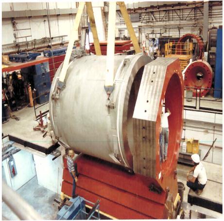
4 Magnet CLEO II magnet to be used for the SoLID spectrometer Solenoid magnet with a uniform axial central field of 1.5 T Large inner space with a clear bore diameter of 2.9 m Coil diameter of 3.1 m, coil length of 3.5 m Built in 1989, operated until 2008 Met with Cornell engineers in June 2014 to discuss design, operation and transport of magnet to Jlab. Details in available trip reports. Items available from Cornell: Superconducting magnet, octagonal iron shielding, cryostat transport frame/cradle, Dynapower DC power supply, valve control box, cryogenic bayonets, data acquisition, rotation/turning jigs, steel mounting blocks, third iron layer (on top of the magnet) + yellow plate to support the 700 liter dewar, transfer lines, readout boxes for strain gauge Projected disassembly in starting in Summer 2015 and transport from Cornell in Summer New information : Recommendation to replace vapor cooled current leads due to significant heat load discuss with Cryo Group.
5 SoLID footprint Hall A Floor Loading 500 ton 500 ton 28 SoLID magnet and detectors encompass an area of 5.8 meters in diameter and 7.3 meters long ton Clearance to the Hall floor ranges from 10 to 38 cm, sufficient for support. Weight of the CLEO-II magnet, detector hut and detectors is 1300 tons. The floor in this installation region is designed for 250 tons for a 12 square foot pad.

6 CLEO II in Hall A The experiment layout puts the HRS arms at 90 degrees to the beamline on the left and right. Alternate layout places both HRS arms to the left of beamline. Target to be 115cm downstream of pivot for magnet to clear pivot bearing. Center of the CLEO-II magnet would be 350 cm downstream of the target center. Hall layout planning is ongoing for SoLID and other experiments.


7 Magnet Modifications NEW PARTS Endcap donut Endcap bottom Endcap nose Collar downstream Front Piece Shield MODIFIED PARTS Barrel Yoke Outer Barrel Yoke Inner Endcap Donut Barrel Yoke Outer Spacer Barrel Yoke Inner Collar Coil Upstream shield Front Piece Spacer Collar Downstream Endcap Bottom Endcap Nose
8 Magnet Modifications The CLEO magnet will require some modifications to its design for use in the SoLID experiments. SoLID will not use the outermost muon ring. It will use the inner two rings, each consisting of 8 slabs of iron. Each of these slabs will have to be shortened to allow the proper position of the endcap. The original upstream coil collar will be reused. The downstream coil collar will be modified if an economical way of reducing its thickness can be found without wasting a majority of its unwanted material. If a solution is not found then a new downstream coil collar will be created. Additional pieces of iron will need to be fabricated to allow for the proper mating of the endcap with the barrel yoke. All supporting structure for the magnet barrel yoke and detector endcap will be new fabrications. The endcap, which consists of the outer cylindrical ring, the backplate, and endcap nose, will all be made from new material.

9 The endcap will be split vertically into halves and be capable of separation to allow for access to the detector package. The endcap nose with a secondary backing plate will be a cast two piece design to allow for separation. Each section of the nose will bolt to the main backplate which consists of a two piece round disk. The two halves of the cylindrical outer ring will bolt to the corresponding backplate.


10 Magnet Support The initial plan used for estimating the cost is to build a stationary frame and distribute the approximate 1000 ton load of the modified CLEO-II magnet section using eight 200 ton enerpac jacks. Steel plates and large steel blocks and/or large I-beams will be used to distribute the load out over a safe area. The 200 ton jacks will be used for vertical alignment and have locking rings which allow for a full mechanical connection and not rely on hydraulic pressure for stationary support.
11 Endcap Support The endcap will have a support structure that cradles each half the cylindrical ring. The structure will be integrated into a track system that is mounted to steel plates resting upon the concrete floor. The initial design concept for the track system requires a set of longitudinal (downstream direction) tracks for moving the endcap away from the magnet. A second set of tracks that would separate the endcap halves in the lateral direction would ride on top of the longitudinal tracks. The endcap support structure would then be attached to the top lateral track system. Motion can be achieved by using hydraulic or electric cylinders to push and pull the entire system into position
12 Detector Supports The magnet will be located adjacent to the existing Hall A center pivot/target mount area and will have limited access to the front of the magnet. The insertion of the large angle detector packages that will reside internal to the cryostat will be accomplished from the downstream side of the magnet using a supporting framework to roll the packages in and out. This will require the detector hut to be moved downstream to allow access to the cryostat. An internal frame system is needed to mount the lead baffles in the PVDIS experiment. The frame cannot come into contact with the inside bore of the cryostat. This requires the frame to span the entire length of the cryostat and mount to the return yoke iron. The rails of the frame will be fabricated from 4 inch diameter schedule 80 welded stainless steel pipe. Either 304 or 316 grade stainless is acceptable. The downstream end of the rails will have a hemispherical cap and a stainless steel foot welded on and will be bolted to the downstream collar. The upstream end of the rail will either be bolted or welded to an annular stainless steel plate. The upstream end of the frame will be mounted to the frontcup Since the frontcup has to be movable to balance the magnetic field on the coils the annular plate will be attached to the frontcup with studs. This will allow the rail framework to remain stationary if the frontcup has to be adjusted. The same rail system can be used for the SIDIS experiment for mounting the large angle calorimeter and GEM s

13 Detector Supports


14 Large Angle Detector and Baffle Installation An installation mechanism is needed to load the large angle detector packages and baffle system into the internal support structure This mechanism will likely be mounted to the longitudinal track system used for the endcap movement and can utilize the tracks for rolling the detectors and baffles into the cryostat and transferring the load to the internal frame.
15 Light Gas Cherenkov Installation The light gas Cherenkov will mount to the external downstream end of the magnet and will not traverse with endcap. When the endcap is in the operational position the light gas Cherenkov will be enclosed within the cylindrical ring along with the rest of the forward angle detectors. The light gas Cherenkov detector will be made up of six pie shaped sections that will need to be bolted to the downstream side of the magnet. A space frame similar to a scaffolding system would hold and position each section while being attached to magnet. The space frame would attach to the rail system and could be movable along the rails if needed. The space frame will be suitable for personnel access to allow workers to perform the installation and maintenance of the detectors
16 Endcap Forward Angle Detector Installation The basic design concept for the detectors mounted inside the endcap will have them supported by individual rails mounted to the inner circumference of the cylindrical ring and on rails attached to the outer horizontal circumferential surface of the nose if needed. The heavy gas Cherenkov will be separated into six sections with each section utilizing two rails to attach the section to the outer circumference of the endcap. A counterweight balanced installation device that is slung from the crane can be used to orient and position each section onto the rails. Personnel access to the endcap will be through man lifts and/or a specialized scaffolding as needed
17 Power Requirements The projected electrical power load is 1.6MVA, maximum current for magnet at 3266A. The present power consumption for Hall A is less than 1 MVA. So upgrade to the Hall substation to have 2 MVA is required The CLEO-II magnet is designed to have a low cryogenic heat load with passive cooling. The HRS arms will not be operational during SoLID, so it is expected that the refrigeration heat load will be less than needed for HRS. Two week cool down while maintaining a 25º delta
18 Magnet Transfer to JLAB Cornell is currently determining the detailed steps required for CLEO II disassembly and working hard to develop a plan based on current variables Project variables include the outcome of their CESR upgrade proposal, timeline of available JLAB funds, and optimizing their schedule while still meeting the minimum amount of run days for their NSF contract. Current planning scenario: Spring and Summer 2015 Preparatory work begins. Removal of scaffolding, adjacent electronics and potentially outer shielding and layer of iron. Summer 2016 Further disassembly of magnet. Cornell will try to maximize amount of work accomplished during this down period to minimize down time in the Summer of Summer Final CLEO removal and shipment of parts to JLAB CESR upgrade will be a concurrent project requiring a good amount of coordination. Experimental equipment and many shielding blocks will be removed during this timeframe.


19 Transport and Storage of CLEO II Disassembled and loaded on trucks for shipping by the Cornell personnel with oversight by Jefferson Lab. It will require 52 trucks to transport the magnet and related equipment. We have identified all of the parts of the CLEO magnet, with sizes and weights, anticipating a need for storage of these parts at Jefferson Lab starting Summer 2016, total weight of 1,053k lbs. The cryostat (35k lbs) and power supply will need to be stored in an environment-controlled area of approximately 400 square feet. Jefferson Lab projects the use of the CMSA site for storage of all parts.
20 Cost and Labor for Magnet K$ and FTE
21 Cost and Labor for Detector Supports and Hall Infrastructure
22 Analysis Additional slides
23 CLEO-II
24
25


26 New downstream coil collar Allowable stress for 1008 hot rolled steel = psi Peak stress due to rigid constraint at the bottom is the only overstress. Conservative simple restraint. Buckling not checked will be retained by the slabs. Forces due to gravity only

 Calorimeter = 23 metric t W forward angle absorber = 13 metric t")
27 Detector hut stress analysis Half of detector weight placed on the outer shell and half on the nose Forces due to gravity only Only overstress is from rigid constraint Light gas Cherenkov = 6 metric t Heavy gas Cherenkov = 8 metric t (assumed) Calorimeter = 23 metric t W forward angle absorber = 13 metric t Outside Inside
Support and Infrastructure
 Support and Infrastructure SoLID Director s Review Whit Seay February 23, 2014 SoLID Experimental Set-ups Design a system for mounting experimental apparatus that can be utilized by both set-ups. Integrate
Zhiwen Zhao (UVa), Paul Reimer (ANL) SoLID Collboration Meeting 2013/03
, Paul Reimer (ANL) SoLID Collboration Meeting 2013/03") Zhiwen Zhao (UVa), Paul Reimer (ANL) SoLID Collboration Meeting 2013/03 CLEO CLEO-II magnet was built in early 1980s by Oxford in England. Coil is divided into 3 sections, each section has two layers Coil
Zhiwen Zhao (UVa), Paul Reimer (ANL) SoLID Collboration Meeting 2013/03 CLEO CLEO-II magnet was built in early 1980s by Oxford in England. Coil is divided into 3 sections, each section has two layers Coil
Created: 4/23/2003 Page: 1 of 12. Abstract
 Collimators and Transport Solenoid Shielding Reference Design Document No: Created: 4/23/2003 Page: 1 of 12 MECO-MUB-03-002 Modified: 10/13/03 Version: 1.01 Prepared by: M. Hebert, V. Tumakov Approved
M. A. Green, and S. Yu Lawrence Berkeley National Laboratory, Berkeley CA 94720, USA
 LBNL-48445 SCMAG-749 SUPERCONDUCTING MAGNETS FOR INDUCTION LINAC PHASE-ROTATION IN A NEUTRINO FACTORY M. A. Green, and S. Yu Lawrence Berkeley National Laboratory, Berkeley CA 94720, USA ABSTRACT The neutrino
Solenoid Magnets for the Front End of a Neutrino Factory
 Solenoid Magnets for the Front End of a Neutrino Factory M.A. Green and S.S. Yu Lawrence Berkeley National Laboratory, Berkeley CA 94720 J.R. Miller and S. Prestemon National High Magnetic Field Laboratory,
SBS Update Mark Jones
 SBS Update Mark Jones 1 SBS experiments Neutron G M Q 2 = 3.5, 4.5, 6.0, 8.5, 10.0, 12.0 and 13.5 GeV 2 25 days of running Extract from ratio of d(e,e n)/d(e,e p) cross sections Neutron G E Q 2 = 1.5,
Hall C SHMS Progress
 Hall C SHMS Progress Paul Brindza Hall C Senior Engineer January 25, 2013 Page 1 SHMS and Magnet Systems Overview Cryo-Control Reservoirs Cryogenics Infrastructure Power Supplies & Controls HB Q1 Q2 Q3
Note on preliminary cost estimate for an integrated tracker for the STAR experiment at RHIC
 Note on preliminary cost estimate for an integrated tracker for the STAR experiment at RHIC Gerrit van Nieuwenhuizen (MIT), Ernst Sichtermann (LBL) and Bernd Surrow (MIT) August 2, 2004 Abstract The following
Mu2e Solenoids! Michael Lamm! L2 for the Mu2e Solenoid! July 27, 2015!
 Mu2e Solenoids Michael Lamm L2 for the Mu2e Solenoid July 27, 2015 Mu2e Solenoids Perform many functions in the Mu2e Experiment One continuous field, generated by 3 unique superconducting solenoid systems
Cryogenic Improvements for the ATLAS Energy Upgrade
 Cryogenic Improvements for the ATLAS Energy Upgrade Cryogenic Operations Workshop May 9-11, 2006 Presented by Steve MacDonald Argonne National Laboratory A Laboratory Operated by The University of Chicago
Draft Working List to be done at CERN for ATLAS Central Solenoid. Originated, Dec. 4, 2001 Revised, Dec.5, 2001 Akira Yamamoto (KEK)
") Draft Working List to be done at CERN for ATLAS Central Solenoid Originated, Dec. 4, 2001 Revised, Dec.5, 2001 Akira Yamamoto (KEK) 1 General Working List Works in Bldg. 180: CS system delivered and acceptance
Draft Working List to be done at CERN for ATLAS Central Solenoid Originated, Dec. 4, 2001 Revised, Dec.5, 2001 Akira Yamamoto (KEK) 1 General Working List Works in Bldg. 180: CS system delivered and acceptance
MOLLER Hybrid Toroid Engineering Design
 MOLLER Hybrid Toroid Engineering Design Presented by Ernie Ihloff, MIT-Bates With Contributions From: Jim Kelsey, MIT-Bates Jason Bessuille, MIT-Bates Presented to MOLLER Collaboration Thursday, 8 th May,
Fabrication of 12 GeV Prototype Quadrupoles 1. Introduction 2. Design 3. Fabrication
 Fabrication of 12 GeV Prototype Quadrupoles T. Hiatt, K. Baggett, M. Beck, L. Harwood, J. Meyers and M. Wiseman Thomas Jefferson National Accelerator Facility, Newport News, Virginia 23606 1. Introduction
Mobile Radiation Shield
 Mobile Radiation Shield December 7, 2001 Design Staff John Fader Rob Horrobin Shaun Kurry Jeff White Mobile Radiation Shield Andy Hegedus Scott Kauffman Advisor: Dr. Wilkins Overview Project Definition
Cryocooler with Cold Compressor for Deep Space Applications
 36 1 Cryocooler with Cold Compressor for Deep Space Applications T.C. Nast 1, B.P.M. Helvensteijn 2, E. Roth 2, J.R. Olson 1, P. Champagne 1, J. R. Maddocks 2 1 Lockheed Martin Space Technology and Research
KSTAR Assembly. National Fusion Research Center, Daejeon, Korea
 1 FT/2-2 KSTAR Assembly H. L. Yang, H. K. Kim, K. M. Kim, J. W. Sa, S. T. Kim, H. T. Kim, K. H. Hong, W. C. Kim, K. H. Kim, Y. S. Kim, J. Y. Kim, C. H. Choi, Y. K. Oh, Y. M. Park, M. Kwon, J. S. Bak, G.
ORDERING: Specify size, figure number, description, nominal pipe size or special O.D. and C-to-C dimension. C - C LOAD lb.
 Fig. 2110 www.pipingtech.com/fig2110 Sway Strut with 4 of Adjustment Engineered spring supports option 1 option 2 ORDERING: Specify size, figure number, description, nominal pipe size or special O.D. and
Front Suspension. Front Suspension Component Layout. NOTE: Without Dynamic Response version shown
 Published: Jan 25, 2005 Front Suspension Front Suspension Component Layout NOTE: Without Dynamic Response version shown 1 Flanged bolt (Upper arm forward bush) 2 Bush - forward (Upper arm) Page 1 of 9
Intermediate weight at 155kg Peak continuous fields up to 3 T for 15mm pole face diameter at 8mm gap Any mounting orientation Fast cycle times
 OVERVIEW The 5405 dipole electromagnet is a fit, form and function upgrade for the 5403 electromagnet system. This upgrade provides approximately 40% more field for a given pole gap. The 5405 is shipped
Report, Test of HIFROST Longitudinal Holding Coil (7/19/6)
") Report, Test of HIFROST Longitudinal Holding Coil (7/19/6) D. Crabb 1, D.G. Haase, B. Jelinek, P. Kingsberry 2, S. Kucuker 1, R. Timberlake and C. Westerfeldt Testing has been successfully completed at
Report, Test of HIFROST Longitudinal Holding Coil (7/19/6) D. Crabb 1, D.G. Haase, B. Jelinek, P. Kingsberry 2, S. Kucuker 1, R. Timberlake and C. Westerfeldt Testing has been successfully completed at
Design Study for Passive Shutdown System of the PGSFR
 Design Study for Passive Shutdown System of the PGSFR 2015. 10. 20 Lee, Jae-Han Koo, Gyeong-Hoi 20151021 IAEA TM on passive shutdown system 1 1. Reactor Control and Shutdown Concepts of PGSFR 6 Primary
FULL VOLTAGE STARTERS z SIZE 8 SERIES B CONSTRUCTION
 505 z 509 FULL VOLTAGE STARTERS z SIZE 8 SERIES B CONSTRUCTION The movable contacts are carried in stainless steel cages which in turn are mounted in cavities in the molded portion of the cross bar. This
EXAMINATION OF NOZZLE INNER RADIUS AND PIPING FROM THE OUTER SURFACE
 More Info at Open Access Database www.ndt.net/?id=18560 ABSTRACT NEW DEVELOPMENTS FOR AUTOMATED NOZZLE INNER RADIUS AND PIPING INSPECTIONS D. Eargle,WesDyne International, USA WesDyne has recently engaged
FUNDAMENTAL SAFETY OVERVIEW VOLUME 2: DESIGN AND SAFETY CHAPTER E: THE REACTOR COOLANT SYSTEM AND RELATED SYSTEMS
 PAGE : 1 / 13 4. PRESSURISER 4.1. DESCRIPTION The pressuriser (PZR) is a pressurised vessel forming part of the reactor coolant pressure boundary (CPP) [RCPB]. It comprises a vertical cylindrical shell,
Update. This week A. B. Kaye, Ph.D. Associate Professor of Physics. Michael Faraday
 10/26/17 Update Last week Completed Sources of Magnetic Fields (Chapter 30) This week A. B. Kaye, Ph.D. Associate Professor of Physics (Chapter 31) Next week 30 October 3 November 2017 Chapter 32 Induction
SUSPENSION 04 CLAMPS
 SUSPENSION CLAMPS 04 4 SUSPENSION CLAMPS 57 Contents General... 58 Suspension clamp trunnion type, forged,... 63 Suspension clamp trunnion type, forged, with bigger angle of deflection, for aluminium based
SAE Mini BAJA: Suspension and Steering
 SAE Mini BAJA: Suspension and Steering By Zane Cross, Kyle Egan, Nick Garry, Trevor Hochhaus Team 11 Progress Report Submitted towards partial fulfillment of the requirements for Mechanical Engineering
Table 4 Magnet Parameters mm
 19 4. The Solenoid Magnet and Flux Return 4.1. Overview The BABAR magnet system consists of a superconducting solenoid [19], a segmented flux return and a field compensating or bucking coil. This system
DAVINCH Lite Chamber Design By Analysis and Full-Scale Testing CWD 2014 London, United Kingdom June 4-6, 2014
 DAVINCH Lite Chamber Design By Analysis and Full-Scale Testing CWD 2014 London, United Kingdom June 4-6, 2014 Robert E. Nickell, Consultant, San Diego, CA, USA Takao Shirakura, Transnuclear, Ltd., Tokyo,
Intermediate weight at 155kg Peak continuous fields up to 3 T for 15mm pole face diameter at 8mm gap Any mounting orientation Fast cycle times
 OVERVIEW The 5405 dipole electromagnet is a fit, form and function upgrade for the 5403 electromagnet system. This upgrade provides approximately 40% more field for a given pole gap. The 5405 is shipped
Powering Schemes for the Strip Trackers
 Powering Schemes for the Strip Trackers Peter W Phillips STFC Rutherford Appleton Laboratory and ATLAS ITk Strip Community ACES, CERN, 8 th March 2016 Outline Proposed CMS Tracker Distribution Scheme Module
WVDP Project Update. Scott Anderson. Deputy General Manager. Citizen Task Force Meeting July 25, 2018
 WVDP Project Update Scott Anderson Deputy General Manager Citizen Task Force Meeting July 25, 2018 www.energy.gov/em 1 Safety Metric June 2018 12-Month Rolling Average TRC (12-Month Rolling Average) DART
Type DTU De-energized Tap Changer Application, Installation & Selection Guide. IL A Instruction Leaflet Page 1 September, 2003
 Type DTU De-energized Tap Changer Application, Installation & Selection Guide IL 44-750-1A Page 1 September, 2003 Page 2 September, 2003 Scope This leaflet contains general information about ordering and
recognized as the best in the industry for over 115 years. Each component is designed with greater innovation and manufactured with higher
 0-0_q_K //0 : PM Page C R A N E C O M P O N E N T S TM TM THERE S A CRANE SOURCE COMPONENT FOR EVERY JOB. CraneSource crane bridge components have been recognized as the best in the industry for over years.
Low Beta Cryomodule Development at Fermilab. Tom Nicol March 2, 2011
 Low Beta Cryomodule Development at Fermilab Tom Nicol March 2, 2011 Concepts of SC CW 3GeV, 1mA Linac H - gun RFQ MEBT SSR0 SSR1 SSR2 β=0.6 β=0.9 ILC RT (~15m) 325 MHz 2.5-160 MeV 650 MHz 0.16-2 GeV 1.3
Central Region Group Status and Positron Region
 Central Region Group Status and Positron Region K. Yokoya 2016.9.14. Posipol2016, LAL 2016/9/14 Posipol2016 1 Issues Discussed in CRWG Positron-related 10Hz operation Auxiliary positron source (APS) Positron
The Results of the KSTAR Superconducting Coil Test
 1 FT/3-2 The Results of the KSTAR Superconducting Coil Test Y. K. Oh, Y. Chu, S. Lee, S. J. Lee, S. Baek, J. S. Kim, K. W. Cho, H. Yonekawa, Y. Chang, K. R. Park, W. Chung, S. H. Lee, S. H. Park, I. S.
Powering Schemes for the Strip Trackers
 Powering Schemes for the Strip Trackers Peter W Phillips STFC Rutherford Appleton Laboratory and ATLAS ITk Strip Community ACES, CERN, 8 th March 2016 Outline Proposed CMS Tracker Distribution Scheme ATLAS
PETRA III Damping Sections
 PETRA III Damping Sections Markus Tischer, HASYLAB 05.05.06 Damping wiggler sections BINP / DESY cooperation on Damping wiggler Vacuum system Absorber M. Tischer PETRA III Damping Sections (MAC meeting,
This chapter gives details of the design, development, and characterization of the
 CHAPTER 5 Electromagnet and its Power Supply This chapter gives details of the design, development, and characterization of the electromagnets used to produce desired magnetic field to confine the plasma,
PWV API 610 Vertical Turbine Pump VS6 (Can Type) VS1 (Sump Type)
 VS1 (Sump Type)") PWV API 610 Vertical Turbine Pump VS6 (Can Type) VS1 (Sump Type) OUTLINE DIMENSIONS VS6 (Can Type) BARREL AND BOWL DIMENSIONS (Inches) BOWL BM APPROX. BOWL WT. (lbs.) SIZE BL & B BN BP E 1st Stg. Add Stg.
PWV API 610 Vertical Turbine Pump VS6 (Can Type) VS1 (Sump Type) OUTLINE DIMENSIONS VS6 (Can Type) BARREL AND BOWL DIMENSIONS (Inches) BOWL BM APPROX. BOWL WT. (lbs.) SIZE BL & B BN BP E 1st Stg. Add Stg.
Present and Future Cryogenics at Cornell
 QuickTime and a TIFF (Uncompressed) decompressor are needed to see this picture. QuickTime and a TIFF (Uncompressed) decompressor are needed to see this picture. QuickTime and a TIFF (Uncompressed) decompressor
BEARINGS The lower bearing assemble is constructed to allow continuous operation when fully submerged in wastewater.
 GENERAL SPECIFICATION INTENT The equipment to be supplied by manufacturer includes the screw pumps, support for the drive unit, profile plates, motors, gearboxes, couplings, guards, upper and lower bearing
FUNCTION OF A BEARING
 Bearing FUNCTION OF A BEARING The main function of a rotating shaft is to transmit power from one end of the line to the other. It needs a good support to ensure stability and frictionless rotation. The
VIBRATING WIRE SURFACE STRAIN GAUGE. Model SM-5B. Roctest Limited, All rights reserved.
 INSTRUCTION MANUAL VIBRATING WIRE SURFACE STRAIN GAUGE Model Roctest Limited, 2012. All rights reserved. This product should be installed and operated only by qualified personnel. Its misuse is potentially
MOS Section Ken McCracken
 MOS Section Ken McCracken July 6, 2004 KHM 1 3D MOS Section KHM 2 MOS Section Component Discussion Vacuum Housing Corrector Optics Wheel Support Plate Dekker Wheel MOS Wheel MOS Plates and Long Slits Wheel
The ATLAS Detector at the Large Hadron Collider. Peter Krieger IPP/University of Toronto
 The ATLAS Detector at the Large Hadron Collider Peter Krieger IPP/University of Toronto The ATLAS Detector at the Large Hadron Collider Peter Krieger IPP/Toronto CAP Congress, Winnipeg 2004 2 Peter Krieger
Chapter 7. Shafts and Shaft Components
 Chapter 7 Shafts and Shaft Components 2 Chapter Outline Introduction Shaft Materials Shaft Layout Shaft Design for Stress Deflection Considerations Critical Speeds for Shafts Miscellaneous Shaft Components
Plain Bearing Technology. ZF end flange mounted bearing
 Plain Bearing Technology ZF end flange mounted bearing Description of the ZF design 02 // 03 The ZOLLERN Group ZOLLERN is one of the pioneers of the metal industry. 3,000 employees at 15 production locations
PROHEAT 35 Induction Heating Application Photos for PREHEAT and PWHT
 PROHEAT 35 Induction Heating Application Photos for PREHEAT and PWHT 2 PREHEAT APPLICATIONS and VARIOUS COIL CONFIGURATIONS FOR PREHEAT 3 Transmission Pipeline Construction - Preheat Transmission pipeline
RETRIEVABLE BOREHOLE EXTENSOMETER. Model BOF-EX. Roctest Limited, All rights reserved.
 INSTRUCTION MANUAL RETRIEVABLE BOREHOLE EXTENSOMETER Model Roctest Limited, 2004. All rights reserved. This product should be installed and operated only by qualified personnel. Its misuse is potentially
LOCATION APPENDIX A. Forward Truss. Aft Dewar Shell. Aft Bulkhead. Number of Ballast Weights. Port. Starboard. Bottom
 APPENDIX A Ballast Weight Station Table LOCATION Forward Truss Aft Dewar Shell Aft Bulkhead Port TEC Truss Starboard TEC Truss Port Starboard Bottom 4 4 5 6 7 8 4 5 6 Number of Ballast Weights GNIRS Service
MRC Field Trial Performance Report (Hugoton Deep Reservoir in Kansas) Revision 1.9
 Revision 1.9") 4 Copyright 2012 - Millennial Research Corporation Page 1 Table of Contents Table of Contents... 2 Table of Figures... 2 Index of Tables... 2 Overview... 3 Description of Equipment... 3 Trial & Test Preparation...
4 Copyright 2012 - Millennial Research Corporation Page 1 Table of Contents Table of Contents... 2 Table of Figures... 2 Index of Tables... 2 Overview... 3 Description of Equipment... 3 Trial & Test Preparation...
International Journal of Computer Engineering and Applications, Volume XII, Special Issue, March 18, ISSN
 DESIGN AND CONSTRUCTION OF LINEAR MOTOR FOR LINEAR COMPRESSOR USED IN HOUSEHOLD REFRIGERATOR Dr. Priya Nitin Gokhale, IEEE Member Professor, Dept of Electrical Engineering Jayawantrao Sawant College of
Peninsula Corridor Electrification Project (PCEP)
") Peninsula Corridor Electrification Project (PCEP) Q4 Quarterly Update #11 April 1 June 30, 2017 JPB Board Meeting August 3, 2017 Agenda Item # 8a Electrification - Infrastructure Design Build Contract
Peninsula Corridor Electrification Project (PCEP) Q4 Quarterly Update #11 April 1 June 30, 2017 JPB Board Meeting August 3, 2017 Agenda Item # 8a Electrification - Infrastructure Design Build Contract
Grove YB Product Guide. Features. ASME B30.5 Imperial 85%, Metric 85%, DIN/ISO. 13,6 t (15 USt) capacity
 capacity") Grove YB5515-2 Product Guide ASME B3.5 Imperial 85%, Metric 85%, DIN/ISO Features 13,6 t (15 USt) capacity 12,5 m (41 ft) three-section, full-power synchronized boom 9,1 t (1 USt) deck carrying capacity
Grove YB5515-2 Product Guide ASME B3.5 Imperial 85%, Metric 85%, DIN/ISO Features 13,6 t (15 USt) capacity 12,5 m (41 ft) three-section, full-power synchronized boom 9,1 t (1 USt) deck carrying capacity
The g-2 Project at FNAL. Horst Friedsam John Kyle IWAA 2014 at Beijing October 2014
 Horst Friedsam John Kyle IWAA 2014 at Beijing 13-17 October 2014 Outline History and project purpose P5 and the Muon Campus development The meaning of the gyromagnetic ratio g Alignment requirements Status
mechanical coupling system
 mechanical coupling system R Since 1981 Depend-O-Lok has offered engineers, contractors, OEM s and system owners an improved pipeline coupling system. Depend-O-Lok products offer strength, longterm reliability,
Faraday's Law of Induction
 Purpose Theory Faraday's Law of Induction a. To investigate the emf induced in a coil that is swinging through a magnetic field; b. To investigate the energy conversion from mechanical energy to electrical
Style 233-L & 234-L Rubber Joints
 Style 33-L & 3-L Rubber Joints Style 33-L Rubber s are designed for piping systems that experience large lateral offsets due to settlement. The Style 33-L is a low profile triple arch design with a built-in
GLAST Large Area Telescope:
 GLAST Large Area Telescope: Gamma-ray Large Area Space Telescope MGSE Integration Readiness Status Two Tower Operations Eric Gawehn SU-SLAC LAT I&T MGSE Dept. Manager egawehn@slac.stanford.edu 650 926
STEEL CASING OVERHEATING ANALYSIS OF OPERATING POWER PIPE-TYPE CABLES
 STEEL CASING OVERHEATING ANALYSIS OF OPERATING POWER PIPE-TYPE CABLES F. P. Dawalibi, J. Liu, S. Fortin, S. Tee, and Y. Yang Safe Engineering Services & technologies ltd. 1544 Viel, Montreal, Quebec, Canada
SECTION AXIAL HVAC FANS
 SECTION 233413 - AXIAL HVAC FANS 1. PART 1 GENERAL 1.1. RELATED DOCUMENTS A. Drawings and general provisions of the Contract, including General and Supplementary Conditions and Division 01 Specification
Link-Belt ES Series Idler Rolls
 Link-Belt ES Series Idler Rolls Introducing the ES Series Idler Rolls from Syntron Material Handling, specifically designed for extreme service in the harsh environment of oil sands extraction. Link-Belt
Galvanized quick connection pipes
 Galvanized quick connection pipes - for best overall economy A complete system which facilitates planning, procurement and assembly Economical Alvenius pipe systems result in lower costs for temporary
PISTON AND CONNECTING ROD
 42 02 PISTON AND CONNECTING ROD 1. No.1 compression ring 2. No.2 compression ring 3. Oil ring Description Cylinder bore diameter Piston outer diameter (D1) Clearance between bore and piston Piston cooling
arxiv: v1 [physics.ins-det] 1 Jul 2014
![arxiv: v1 [physics.ins-det] 1 Jul 2014](/thumbs/80/81223009.jpg "arxiv: v1 [physics.ins-det] 1 Jul 2014") Construction and test of high precision drift-tube (smdt) chambers for the ATLAS muon spectrometer arxiv:1407.085v1 [physics.ins-det] 1 Jul 014 Sebastian NOWAK E-mail: nowak@mppmu.mpg.de Oliver KORTNER
Construction and test of high precision drift-tube (smdt) chambers for the ATLAS muon spectrometer arxiv:1407.085v1 [physics.ins-det] 1 Jul 014 Sebastian NOWAK E-mail: nowak@mppmu.mpg.de Oliver KORTNER
CASING SPACERS DESIGNED FOR WATER, SEWER, OIL & GAS
 CASING SPACERS DESIGNED FOR WATER TER,, SEWER,, OIL & GAS The BWM Company P.O. Box 1 Forest City, North Carolina 2803 Phone: 828.27.030 Toll Free 8 5 SPACER Fax: 828.25.59 www.bwmcompany.com BWM will provide
Enerpac Hydraulic Presses
 Enerpac Hydraulic es Enerpac Hydraulic es are available in a variety of capacities and sizes. The press frames are designed for maximum strength and durability. Strong frames and powerful high-pressure
Maglev Plus System. 1. Description
 1. Description Maglev Plus System The Maglev Plus System is specifically designed to levitate various objects attached to a very strong disc magnet. It can levitate up to 25 g additional mass. The vertical
Mustang Differential Gears - Installation Instructions
 Mustang Differential Gears - Installation Instructions The below installation instructions work for the following products: Ford Racing Gears - 3.73 Gears for 8.8" Ford Rear End Ford Racing Gears - FRPP
Recommended BFV Installation, Maintenance & Repair Procedures Ultraflo 300 & 400 Series Valves
 I. Introduction Recommended BFV Installation, Maintenance & Repair Procedures Ultraflo 300 & 400 Series Valves A. Butterfly Valve Seat / Disc Function The seat in most resilient-seated butterfly valves
Quarterly Progress Report
 Quarterly Progress Report Period of Performance: January 1 March 31, 2006 Prepared by: Dr. Kuo-Ta Hsieh Principal Investigator Institute for Advanced Technology The University of Texas at Austin 3925 W.
General Purpose Clutches FSO/HPI
 General Purpose Clutches FSO/HPI Overrunning, Indexing, Backstopping Ball Bearing Supported, Sprag Clutches Model FSO General purpose, ball-bearing clutches suitable for overrunning, backstopping and light
Series 230 Rubber Joints
 Series 230 Rubber Joints Series 230 Rubber Expansion Joints are designed for piping systems to absorb pipe movements, relieve stress, reduce system noise/vibration, compensate for misalignment/offset and
Interlocks 325 Series
 rd 12070 43 St. NE, St. Michael, MN 55376 763-497-7000 www.tcamerican.com sales@tcamerican.com Installation Instructions Interlocks 325 Series 3I-615; 3I-430 3I-613; 3I-450 Crane Interlock and Operating
VSC /VSCS Pumps Technical Brochure
 VSC /VSCS Pumps Technical Brochure BX-4C VSC/VSCS Construction Materials STANDARD SEAL CONFIGURATION PART NAME STANDARD CONSTRUCTION ASTM NO. Casing Cast iron A159 Class G0 Volute cover plate (Outboard)
THE 12 GeV ENERGY UPGRADE AT JEFFERSON LABORATORY
 THE 12 GeV ENERGY UPGRADE AT JEFFERSON LABORATORY F. Pilat Thomas Jefferson National Accelerator Facility, Newport News, VA 23606, USA Abstract Jefferson Laboratory has undertaken a major upgrade of its
MM Tubular K-Member, (Mm5KM-7)
") 3430 Sacramento Dr., Unit D San Luis Obispo, CA 93401 Telephone: 805/544-8748 Fax: 805/544-8645 www.maximummotorsports.com MM Tubular K-Member, 2005-14 (Mm5KM-7) This Kit Contains Congratulations on purchasing
3430 Sacramento Dr., Unit D San Luis Obispo, CA 93401 Telephone: 805/544-8748 Fax: 805/544-8645 www.maximummotorsports.com MM Tubular K-Member, 2005-14 (Mm5KM-7) This Kit Contains Congratulations on purchasing
AUTOMATED POWER CATWALK
 AUTOMATED POWER CATWALK H E L P I N G O U R C U S T O M E R S A C H I E V E S U P E R I O R R E S U L T S The Automated Power Catwalk is simple to use and extremely robust. It combines innovative engineering
Urea Reactor Height Extension to Increase Capacity
 Technical Paper June 2014 Urea Reactor Height Extension to Increase Capacity Hermann Kernberger Schoeller-Bleckmann Nitec GmbH (SBN), Austria Bob Edmondson Yara Belle Plaine, Canada Summary A discussion
12.- Rails. Crane, by Ternium, A 100 rail. 2 ( 239 and 240 ) Speed ( m / min. ) 15 ( at 50 Hertz )/1.5 ( at 5 Hertz )
 Speed ( m / min. ) 15 ( at 50 Hertz )/1.5 ( at 5 Hertz )") 7.- Rated load. ( Metric ton ) 75 ( 50 below magnets ) 8.- Span. ( mm ) 21270 9.- Required hook lift. ( mm ) 8000 10.- Distance between hooks and centerline of rails. ( mm ) L side 3270 M side 2000 11.-
7.- Rated load. ( Metric ton ) 75 ( 50 below magnets ) 8.- Span. ( mm ) 21270 9.- Required hook lift. ( mm ) 8000 10.- Distance between hooks and centerline of rails. ( mm ) L side 3270 M side 2000 11.-
Service Bulletin No.: DA Rev 0 Date Issued: 8 January, 1999 Title: Nose Gear Fork, Fatigue Page: 1 of 6
 Title: Nose Gear Fork, Fatigue Page: 1 of 6 1. ATA Code: 3220 2. Effectivity: DA20-A1 aircraft. 3. General: As a result of hard landings, cracks have appeared in the nose landing gear fork of some aircraft.
Steering Column. Steering Column Component Layout.
 Page 1 of 9 Published : May 5, 2004 Steering Column Steering Column Component Layout Item Part Number Description 1 - Screw (3 off) 2 - Steering angle sensor 3 - Upper steering column assembly 4 - Cowl
Vehicle Design, Construction, and Operation
 9 Chapter 2 Vehicle Design, Construction, and Operation 2.1 Introduction This chapter describes the design of the vehicle and provides a detailed description of the construction and operation. Section
NUCLEAR POWER INDUSTRY
 FLOW BALANCING The objective of the simulation is to model the flow rates through the respective distribution holes of the inlet manifold. This was required to initially determine the appropriate size
Parts Manual Rev. A RZT48 /
 115 91 36-2 Rev. A Parts Manual RZT48 / 96 62001-00 Please read the operator manual carefully and make sure you understand the instructions before using the machine. Gasoline containing a maximum of 10%
Decision on Merced Irrigation District Transition Agreement
 California Independent System Operator Corporation Memorandum To: ISO Board of Governors From: Karen Edson, Vice President Policy & Client Services Date: March 13, 2013 Re: Decision on Merced Irrigation
radial GATES Waterman Industries of Egypt
 radial GATES USES Maintenance of water elevations in canals Increased storage capacity for reservoirs Diversion of water for irrigation Flow control preserving wide, clear waterways Other areas requiring
Beam Energy Absorber and
 ADS Workshop VirginiaTech, September 2010 Beam Energy Absorber and Converter with Moving Core Pavel Degtiarenko ESH&Q Division, JLab 1 Contents Brief review Properties of High Power and High Energy Beam
T95 Load Cell Assembly for Silo, Tank & Vessel Weighing and Axle Weighing
 T95 Load Cell Assembly for Silo, Tank & Vessel Weighing and Axle Weighing Capacities 2t to 20t Stainless Steel Load Sensor OIML C3 approved Integrated Lift Off Prevention Load cell is always in Tension
Nanometrics Solar Power System
 Nanometrics Solar Power System Installation Guide Nanometrics Inc. Kanata, Ontario Canada 2003 Nanometrics Inc. All Rights Reserved. Installation Guide The information in this document has been carefully
RIGID, ADJUSTABLE SUPPORT OF ALIGNED ELEMENTS VIA SIX STRUTS
 RIGID, ADJUSTABLE SUPPORT OF ALIGNED ELEMENTS VIA SIX STRUTS William Thur, Richard DeMarco, Bill Baldock, Ken Rex Lawrence Berkeley National Laboratory One Cyclotron Road, Berkeley, Ca. 94720 October,
PID 274 Feasibility Study Report 13.7 MW Distribution Inter-Connection Buras Substation
 PID 274 Feasibility Study Report 13.7 MW Distribution Inter-Connection Buras Substation Prepared by: Entergy Services, Inc. T & D Planning L-ENT-17A 639 Loyola Avenue New Orleans, LA 70113 Rev Issue Date
G&L Pumps. TECHNICAL Brochure BAC8100. Series A-C 8100 SPLIT CASE PUMPS
 TECHNICAL Brochure BAC8 Series A-C 8 SPLIT CASE PUMPS TABLE OF CONTENTS Useful Pump Formulas 2 Performance Curves 3-5 Materials of Construction (Standard) 6 Materials of Construction (Optional) 7 Pump
Parts Manual Rev. B RZT48 /
 115 91 36-2 Rev. B Parts Manual RZT48 / 96 62001-00 Please read the operator manual carefully and make sure you understand the instructions before using the machine. Gasoline containing a maximum of 10%
Peninsula Corridor Electrification Project (PCEP)
") Peninsula Corridor Electrification Project (PCEP) Q2 Quarterly Update #13 October 1 December 31, 2017 JPB Board Meeting February 1, 2018 Agenda Item # 8b Electrification - Infrastructure Progression of
Peninsula Corridor Electrification Project (PCEP) Q2 Quarterly Update #13 October 1 December 31, 2017 JPB Board Meeting February 1, 2018 Agenda Item # 8b Electrification - Infrastructure Progression of
FRONT & REAR SUSPENSION SECTIONSU CONTENTS IDX. FRONT SUSPENSION...2 Precautions...2
 FRONT & REAR SUSPENSION SECTIONSU GI MA EM LC CONTENTS EC FE FRONT SUSPENSION...2 Precautions...2 PRECAUTIONS...2 Preparation...2 SPECIAL SERVICE TOOLS...2 COMMERCIAL SERVICE TOOLS...2 Noise, Vibration
CONFIGURATION DESIGN AND MAINTENANCE APPROACH FOR THE ARIES-CS STELLARATOR POWER PLANT
 CONFIGURATION DESIGN AND MAINTENANCE APPROACH FOR THE ARIES-CS STELLARATOR POWER PLANT X.R. Wang 1, S. Malang 2, A. R. Raffray 1 and The ARIES Team 1 University of California, San Diego, CA, 9500 Gilman
Design and Test of Transonic Compressor Rotor with Tandem Cascade
 Proceedings of the International Gas Turbine Congress 2003 Tokyo November 2-7, 2003 IGTC2003Tokyo TS-108 Design and Test of Transonic Compressor Rotor with Tandem Cascade Yusuke SAKAI, Akinori MATSUOKA,