VM Carb Rebuild Paul Musser October 2005 v1.0
|
|
|
- Pamela Williamson
- 5 years ago
- Views:
Transcription
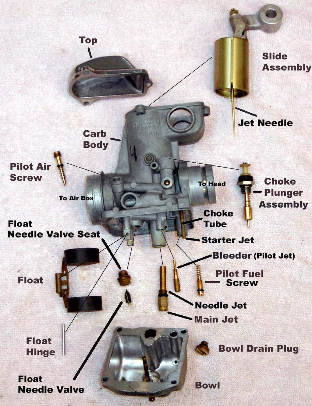
1 VM Carb Rebuild Paul Musser October 2005 v1.0 A big thank you to all the folks at GS Resources ( for their invaluable assistance. Much of the information for his document came from studying threads and posts in the forum. Special thanks to Keith Krause for his help reviewing the document and his many suggestions for improvement. This document and pictures are based on a 1978 GS750EC. Other cylinder GS bikes should be similar and later 4 cylinder GSs (and the 77 and later two cylinder bikes) use a CV carb which is a little different. There s another document on the GS Resources site that covers rebuilding the CV carbs. Before you start Read your manuals and study the diagrams. If at all possible while rebuilding, clean and reuse the stock parts (the metal parts, not the o-rings and gaskets) instead of the lower-quality items in the rebuild kits. Sometimes it's unavoidable if there's damage, severe wear, or no way to get the stock parts clean. Find a place to work with enough room to lay out the parts as you remove them. Keep all parts on a towel. I used four egg cartons for the small parts one for each carb. That way I could easily keep the parts for each carb together. If you're worried about putting things back correctly, you can do one carb at a time or take them all apart except one, but it's harder to do that way and it s not necessary. There are enough differences between the parts that you can t mistakenly put one part in another s place. When unscrewing the small brass parts with a slotted screwdriver, be sure to use a screwdriver with a tip that fits the slot. That will greatly increase the chance of removing them without stripping the slot. Use carb spray with a tube attached to the nozzle. This really does a good job with varnish buildup. Use compressed air to blow out all the small passages. Be careful of back spray in your face or on painted or plastic items in the area. Sometimes when you spray or blow in a hole it comes right back at you or in some other unexpected direction. If you have a digital camera, take lots of pictures especially before you remove the carbs and before you disassemble them. They will be a huge help when putting things back together, especially routing hoses. Parts you will need: Carb o-ring set. Complete, well-labeled sets are available from a GS Resources member at O-rings for carb/cylinder head boots. Get genuine Suzuki parts; they are made from a special rubber. Bowl gaskets Top cover gaskets
2 You may be able to reuse the top and bowl gaskets, but I would have some on hand in case they have to be replaced. You don t want to have to wait for a week or two to get them. You can purchase carb rebuild kits from a lot of sources. They don t all have the same parts so be sure you know what you re getting. They almost all have the top and bowl gaskets, and a new float needle valve and seat. Others will have some or all of the jets, o-rings, and/or springs. Tools and materials you will need: Carb dip. Berryman s is one brand it s a gallon can with a tray for parts that you can submerge so they can soak in the cleaner. Gunk also makes one that is reported to be more environmentally friendly and do a better job. Carb cleaner spray with nozzle High-temp synthetic grease for the pivots on the slide assemblies. High-temp bearing grease for the o-rings on the carb/cylinder head boots. Air compressor or other compressed air source Dental picks, toothpicks and Q-tips for the nooks and crannies be careful not to leave strands of cotton anywhere Assorted screwdrivers and wrenches Wax pencil or crayon to label the carb bodies Lots of rags
3

4 Remove carbs from bike 1. Remove the fuel line and vacuum hose from the petcock. 2. Remove the fuel tank. 3. Remove the crankcase breather hose at the airbox. 4. Remove the two bolts holding the airbox to the frame. 5. Loosen the screws on the carb/airbox boot clamps. 6. Remove the airbox. It can be a little tricky. Watch out for wires you can snag them. And watch out for the drain hose on the bottom of the airbox. 7. Detach the throttle cables. 8. Before you take the carbs off, loosen the bolt for the throttle shaft stopper plate. It can be very tight and more difficult to loosen when the carbs are off the bike. It s between the #1 and #2 carb and fits in a groove in the throttle shaft to keep the shaft from moving side to side. 9. Loosen the screws on the head/carb boot clamps. 10. Remove the carbs. 11. Label each carb body with wax pencil 1-4. #1 is on the far left as you sit on the bike. 12. Remove the rubber manifold boots that go between the carbs and cylinder head. Carb bodies 1. Remove the screws holding the carb bodies to the mounting plate and remove the plate. 2. Separate the carb bodies; remove the fuel lines and tee and the short sections of hose between the vacuum ports. 3. Remove the rubber seals that the throttle shaft runs through. 4. Once all rubber and plastic parts are off, use a carb dip and/or liberal amounts of spray carb cleaner and clean the carb bodies thoroughly. Use compressed air to blow out all passages. Pay special attention to the small hole(s) in the main throat. Carefully (watch for back spray in your face) spray every hole and passage you can see. Try to see spray exiting out at some other point to be sure that passage is clear. Clean them one at a time and relabel each one after it is cleaned (1, 2, 3, or 4). Disassemble Carbs Remove Throttle Shaft 1. Remove the throttle pulley spring. 2. Remove the carb tops. 3. Remove the stopper plate note the little pin on one side. 4. Remove the bolts that mount to the throttle shaft. One bolt holds the throttle cable pulley on the shaft and the other 4 are under the carb tops. 5. Take off the outside rubber plugs and push the throttle shaft out. It helps to twist as you pull. 6. Take out the 4 slide assemblies. Keep them in order so they can be returned to the same carb body. Remove Choke Shaft, Lifters, and Plunger Assemblies 1. Loosen the 4 screws that hold the choke lifters to the choke shaft. 2. Remove the shaft spring and screw on the left and pull out the shaft. Watch for a small spacer washer under the slotted part. 3. Remove the 4 choke plunger assemblies. 4. Disassemble and clean thoroughly. There is a rubber seal on the bottom of the plunger that cannot be removed and should not be exposed to carb cleaner. Clean with kerosene and brush. 5. Replace the o-rings.


5 Pilot air screws also known as side air screws, or pilot screws, control air flow into the idle circuit. These are set at the factory for each cylinder there is no standard setting. Before removing them, count the turns to bottom each screw and record the number so you can set them back there when you reassemble. 1. If they are sealed with paint, put a few drops of spray carb cleaner on them and let it sit for a few minutes. That should soften the paint. Use a GOOD fitting tool. 2. See if there is a nick next to the screw head lined up with one end of the screw slot. That is put there by the factory to help reposition the screw if it s removed. Turn each one in until it bottoms, counting the turn(s). Write down the number of turns then unscrew and remove. 3. Clean out any junk in the screw threads and remove the screws and spring and any washers. 4. Clean thoroughly. 5. Replace the o-rings. Float Bowl, drain plug, float, and float needle valve 1. Remove the float bowl. Be careful scraping off the gasket material the bowl has a ridge under the gasket to improve the seal a razor blade or knife can easily scrape the ridge off. 2. Remove the drain plug and clean thoroughly especially the center and side holes. They allow the bowl to drain without completely removing the plug. 3. Replace the drain plug o-ring. 4. Remove the float pin and note which way is "up" on the float. 5. Remove the float needle valve and the seat that the valve sits in. You should be able to reuse the washer under the seat. Keep the float needle valve and seat for each carb together and replace (if necessary) as a pair. 6. Pay close attention to the spring tension on the jet needles the aftermarket ones are commonly very weak, and will allow the gas level in the float bowls to be too high. Pilot fuel screws, also known as Pilot Screws, control fuel flow into the idle circuit. These are set at the factory for each cylinder there is no standard setting. They are generally ¾ to 1¼ turns out from the factory. For a bike with a stock airbox and exhaust start at 1 turn. Before removing them, count the turns to gently bottom each screw and record the number so you can set them back there when you reassemble. 1. If they are sealed with paint, put a few drops of carb cleaner on them and let it sit for a few minutes. That should soften the paint. Use a screwdriver that fits the slot.
. Write down the number for each carb. CAUTION, when seating these screws, seat them LIGHTLY. They have a sharp tip that can easily break off in the carb body.")


6 2. See if there is a nick next to the screw head lined up with one end of the screw slot. That is put there by the factory to help reposition the screw if it s removed. Turn them IN first, counting the turn(s). Write down the number for each carb. CAUTION, when seating these screws, seat them LIGHTLY. They have a sharp tip that can easily break off in the carb body. Because the threads are gunked up with the paint, they may be very stiff to turn, making it even harder to tell when they re bottomed. Put some carb cleaner on the screw and wait for it to soften the paint. As you re turning the screw in, go back and forth to further loosen the paint in the threads. (Don t lose your count!) Adding a few more drops of carb cleaner will also help. By the time you re close to the bottom, it should be turning easily enough so you can tell when it is gently bottomed. 3. Clean out any paint in the threads while the screw is bottomed so it doesn t build up when the screw is removed. 4. Remove the screws and springs. 5. Clean thoroughly. 6. Replace the o-ring. Main jet and needle jet 1. Remove the needle jet and main jet. 2. Clean thoroughly. 3. Replace the o-ring on needle jet. Bleeder (Pilot Jet) 1. Remove the bleeder. 2. Clean thoroughly. Note it does not have an o-ring. Slide assembly 1. Remove the two phillips screws (down inside the top of the slide) that hold the linkage to the slide. Note the orientation of the plate under the linkage the third hole lines up with the hole in the top of the slide. 2. Remove the needle. Note the position of the plastic washer and spacer, and write down the position of the clip. 3. Clean thoroughly, including each end of the linkage.

7 Slide assembly disassembled

8 Fuel lines and Tee 1. There are two types of fuel lines and tees some have slots for o-rings (preferred) and some have a rubber sleeve with o-ring-like ridges (pictured). The rubber sleeves are no longer available and if disturbed may not seal again. You will then be forced to fabricate custom fittings or find some that use the o-rings. If extensive deep cleaning of the carb bodies is not necessary you may want to consider keeping them together and cleaning them as a unit. To tell if you have the sleeve type, look between the fitting and the fuel inlet on the carb body. The rubber sleeve is visible. 2. Clean thoroughly. 3. Replace the o-rings if they have them. Reassembly For each carb 1. Screw the main jet into the needle jet. Screw the needle jet (with a new o-ring) into the carb. 2. Screw in the bleeder (pilot) jet. 3. Screw in pilot fuel jet (with new o-ring) until it gently bottoms, then back it out the number of turns you recorded earlier, set to 1 turn out if you re not sure of the original setting. Final adjustments must be made with plug readings. See below. 4. Screw in the float needle valve seat with washer, then place the needle valve into the seat, position the float, and put the float hinge pin in place. 5. Adjust the float height to 24mm by measuring between the bottom of the float to the carb body at the gasket-mating surface (without the gasket) when the tab on the float just touches the needle. To adjust, bend the tab that rests on the needle valve. Measure both sides to be sure the two floats are even. 6. Screw the bowl drain plug (with new o-ring) into the bowl bottom. 7. Screw in the side pilot air screw (with new o-ring) until it bottoms, then back it out the number of turns you recorded earlier. Set to 1¼ if you re not sure of the original setting. Final adjustments must be made while running at idle. See below. 8. Screw in the choke plunger assembly (with new o-ring). 9. Attach the bowl (with gasket) to bottom of the carb body. 10. Reposition the rubber seals for the throttle shaft leaving off the end caps for now. 11. Place the fuel lines into the holes on the sides of carbs with the tee in the middle. At the same time place the short sections of rubber hose between the vacuum ports on the carb bodies. 12. Attach the carb bodies to the mounting plate use blue threadlock on the screws. Final assembly 13. Install the slider assemblies the slot on slider lines up with the raised guide in carb body. Gently lower the slide being careful that the jet needle goes into the needle jet. 14. Lightly grease the throttle shaft. Put the throttle pulley in position and install the throttle shaft. You can determine which direction the shaft should go by looking for the 5th threaded hole for the throttle pulley and the groove for the stopper plate. Put some extra grease in the 3 grooves on the shaft just before you slide them into the bearings. Use blue thread lock on the bolts. Torque to 3.5 ft lbs (42 in lbs). Over tightening can cause binding and add to sync problems. 15. Install the choke shaft and lifters. Make sure each choke lifter goes on right-side up. They have a "bump" that contacts the plunger shaft and if you put some of them back in upside down, your plungers may be out of sync. There may be a little divot next to the screw. That faces down.
9 16. Perform a manual sync. If you already installed the idle screw, be sure there is clearance between it and the throttle pulley. Fully closed position Hold the carbs with the engine side of the carbs facing you. On top of the throttle valve arm is a slotted screw held by a nut. Loosen all 4 nuts, then all 4 screws. Start with the #3 carb. While watching the bottom of the carb slide, turn the slotted screw to fully close the valve (or as much as the slide will drop down). DO NOT turn it any more than necessary. When the slide stops dropping, stop turning. Do the other 3 the same way. Now carefully hold the slotted screws so they can't move and tighten the holding nuts. 3 ft/lb is good don't over-tighten. If you think the screws moved when you tightened the nuts, re-sync. When done, the bottoms of the slides should look uniform to the eye. Fully open position On the carb bracket, by the throttle pulley, there is a slotted screw under spring tension the throttle stop screw. When you fully open the throttle, the pulley will stop when it hits this screw. Turn the carbs so the airbox side is facing you. Raise the slides fully by pushing up the pulley until it hits the screw. Hold it there. Look up inside the rear of the carbs and note the bottom of the slides. The bottom of the slides should be 0.5 to 1 mm above the top of the intake chamber. If an adjustment is needed, turn the screw in to decrease this gap and out to increase the gap. 17. Install the idle screw knob with spring. After the screw contacts the pulley, give it another two turns. That should be enough to allow the bike to start. 18. Install the rubber manifold boots on the cylinder head. It is very important to replace the o- rings Give them a good coat of hi-temp' bearing grease and torque them to about 6 ft/lbs don't over-tighten that flattens the o-rings too much and decreases their service life. 19. Put the fuel line and clamp on the tee between carbs 2 and Install carbs onto manifold boots. 21. Install airbox on to carbs. Be sure the boots are not pinched and the carbs are fully seated. 22. Tighten the screws on manifold boot clamps. 23. Tighten the screws on carb/airbox boot clamps. 24. Install the bolts on the brackets on top of the air box that secure it to the frame. 25. Attach the throttle cables. 26. Attach a bowl vent/overflow hose to the nipple on the bottom of each bowl. Route them to the right frame and through the plastic strap and down in front of the swing arm. 27. Attach the hoses to the nipples on carbs #2, 3 and 4. Route #2 and 4 hoses over the airbox and through the guide that is toward the right on the back of the airbox. They just vent to air. The hose on #3 will go to the petcock. 28. Attach the crankcase breather hose to the airbox. 29. Install the fuel tank you may want to use an auxiliary fuel tank or set your fuel tank on a table next to the bike and run longer hoses to it. It needs to be off the bike to synchronize the carbs. 30. Attach fuel line from tee, and vacuum hose from #3 carb, to the petcock. 31. Turn the petcock to Prime (Pri) to fill the bowls. If any overflows through the vent hoses, turn the petcock back to Run (On) and tap the offending bowl lightly with a screwdriver handle. That may free up the float. If that doesn t help there may be dirt between the float needle and seat or they are bad and need to be replaced. 32. You can check the float height by attaching a special tool where the bowl drain plug goes and using a clear hose the fuel level should be even with the top of the bowl. 33. Before doing any other tuning be sure the valves are adjusted and the timing is set. 34. Start the bike and let it warm up.
10 35. Set the idle to 1100 rpm. 36. Turn each side pilot air screw slowly (both ways) up to one full turn until you hear the engine speed max out. When the engine speed stops rising, stop turning. You may want to go back about ⅛ turn to allow for listening error. These screws usually end up about 1¼ to 2 turns out. Now turn the idle down to 1100 rpm using the idle adjuster knob. Go to the next carb and do the same thing until all four are set and the idle is set. Turning them in decreases air flow and richens the mixture. Turning them out increases air flow and leans the mixture. 37. Using a manometer, sync the carbs. a. Remove the fuel tank and the tops of the carbs b. Use the idle adjuster to set the engine speed to 2,500 to 3,500 rpm. Be sure to use several fans to keep good airflow going straight onto the engine from the front. The engine will overheat easily at that speed during the time it takes to do the sync. c. All four carbs should pull the same vacuum. If your manual sync was done carefully, they should be close. d. If they are different, loosen the locknut at the top of the slide of the carb with the highest vacuum and adjust the screw to match the lowest vacuum. Repeat until they are even. e. Replace the carb tops and fuel tank. 38. To fine tune the pilot fuel screws, you'll have to test and take plug readings. Turning the screw out increases fuel flow and richens mixture. Turning it in decreases fuel flow and leans the mixture. Keep record of any adjustments. Even a ⅛ turn will affect plug color over time. You may find that your final adjustments are not all equal. That is normal. The pilot fuel screws are intended to fine tune the pilot circuit and because of differences in each cylinder, the screws may have to be set differently from each other to get a uniform burn. These screws are sensitive and it can take some patience to get the pilot circuit right. Adjusting the pilot fuel screw will affect the mixture, so you have to re-tune the pilot air screws (for highest idle) after making adjustments to the pilot fuel jets. You may not notice any change in settings, but you should always re-check them. One way to accurately get pilot circuit plug reads is to ride the bike around at a steady speed of about 30 mph in 4th gear. A few miles should be good and to avoid any color influence by choking the bike when it was cold. It's still better to do a "chop test" at the end of a longer ride though. As you pull into your driveway, quickly pull in the clutch and close the throttle and turn off the ignition. Coast with the clutch in to a stop and check the plug colors. Because the vacuum fluctuates so much at idle with these carbs, if you allow the bike to idle before this plug read, you'll get inaccurate results. Do what the plugs and performance tell you. Obvious signs such as inability to hold a colder idle or slow warm up indicate the pilot screws are set too lean. A stumble just off idle is usually a lean condition too. Excessive popping on deceleration indicates a lean condition. If it is very slow to return to idle it usually indicates a lean condition. If the bike is idling correctly and "blipping" the throttle once causes the engine speed to momentarily drop below the set idle, this suggests a rich condition. Don't try to trick the carbs and blip as quickly as you can, just a normal blip. Perfectly operating VM carbs can be "gagged" by blipping quicker than you would during normal riding and stops. If you have trouble with re-starting and low speed riding at high elevations, try turning the side air screws OUT (leaner) about a ¼ turn or so. Set them back when out of the high elevation.
Adjusting Carbs For Re-Jetting (Procedure written for an Intruder 1500 LC) NEWLY UPDATED: APRIL 2003
 NEWLY UPDATED: APRIL 2003") SECTION ONE: Get Prepared - Tools Adjusting Carbs For Re-Jetting (Procedure written for an Intruder 1500 LC) NEWLY UPDATED: APRIL 2003 Courtesy of: Half-Crazy Get a manual impact driver (the kind you hit
SECTION ONE: Get Prepared - Tools Adjusting Carbs For Re-Jetting (Procedure written for an Intruder 1500 LC) NEWLY UPDATED: APRIL 2003 Courtesy of: Half-Crazy Get a manual impact driver (the kind you hit
Mikuni RS Carburetor Conversion
 Mikuni RS Carburetor Conversion After putting your carbies on the bench or the kitchen table if the wife is out, you will see that the linkages may be in different positions depending on which brand of
Tillotson Tc3A Carburator
 Tillotson Tc3A Carburator 176 FUEL SYSTEMS - 5B-11 CENTER BOWL TYPE CARBURETOR Removal 1. Remove front cowl cover and wrap-around cowl. 2. Remove swivel link from lower carburetor. (Figure 2) 3. Loosen
HSR Carburetor Easy Kits Installation Instructions For Evo Big Twin Kit: # 42-7 Twin Cam Kit: # 42-18
 HSR Carburetor Easy Kits Installation Instructions For Evo Big Twin Kit: # 42-7 Twin Cam Kit: # 42-18 Revised 5/01/01 EK-1 Easy Kit Installation Instructions The HSR series carburetors are precise yet
BA /02/03/04/06/07/08/13/13B/15 BIG AIR KIT (BAK) - Yamaha Road Star (99-07)
 - Yamaha Road Star (99-07)") BA-2020-00/02/03/04/06/07/08/13/13B/15 BIG AIR KIT (BAK) - Yamaha Road Star (99-07) Page: 1 Revision: 6.2-02/23/2011 Install Time: 1.5 Hours We recommend a qualified Yamaha technician install this kit
BA-2020-00/02/03/04/06/07/08/13/13B/15 BIG AIR KIT (BAK) - Yamaha Road Star (99-07) Page: 1 Revision: 6.2-02/23/2011 Install Time: 1.5 Hours We recommend a qualified Yamaha technician install this kit
Prerequisites: Shop Manual (recommended) pages 3-9 through 3-13.
 pages 3-9 through 3-13.") Prerequisites: Order your gaskets average about $25.00 bucks X 2 so $50.00 4NK-11193-00-00 Obtain a shim kit (Should have several 265 and 270s) (Some dealers will exchange) Obtain a Valve Bucket Tool YM-33961
Prerequisites: Order your gaskets average about $25.00 bucks X 2 so $50.00 4NK-11193-00-00 Obtain a shim kit (Should have several 265 and 270s) (Some dealers will exchange) Obtain a Valve Bucket Tool YM-33961
HSR Carburetor. Total Kits. Installation Instructions. # Evo Big Twin # present Twin Cam
 HSR Carburetor Total Kits Installation Instructions HSR42 Kits: HSR45 Kits: #42-8 84-99 Evo Big Twin #42-19 99 - present Twin Cam #45-2 84-99 Evo Big Twin #45-3 84-99 Evo Big Twin #45-4 99 - present Twin
Урал) - Dnepr (Днепр) Russian Motorcycle Carburetors
 - Dnepr (Днепр) Russian Motorcycle Carburetors") Ural (Урал( Урал) - Dnepr (Днепр) Russian Motorcycle Carburetors Part 8A: Adjustment and Overhaul of the Pekar K-65 Carburetors (see also Part 8-8 K-65 Carburetor and Part 8B- Setting Up K-65 K Carbs)
Ural (Урал( Урал) - Dnepr (Днепр) Russian Motorcycle Carburetors Part 8A: Adjustment and Overhaul of the Pekar K-65 Carburetors (see also Part 8-8 K-65 Carburetor and Part 8B- Setting Up K-65 K Carbs)
HSR Carburetor. Total Kits. Installation Instructions. # Evo Big Twin # present Twin Cam
 HSR Carburetor Total Kits Installation Instructions HSR42 Kits: HSR45 Kits: #42-8 84-99 Evo Big Twin #42-19 99 - present Twin Cam #45-2 84-99 Evo Big Twin #45-3 84-99 Evo Big Twin #45-4 99 - present Twin
THE IDIOT S GUIDE TO TUNING SU CARBURETTERS
 THE IDIOT S GUIDE TO TUNING SU CARBURETTERS There are four distinct phases to tuning SU carburetters (carbies). The first is to set the fuel level in the float bowl, the second is to centre the needle
KEIHIN CARBURATORS FOR 4-CYLINDER HONDA MOTORCYCLES
 KEIHIN CARBURATORS FOR 4-CYLINDER HONDA MOTORCYCLES Set of 4 Keihin carburetors marked 089A and used on 1976 CB550K GENERAL NOTES: All carburetors perform the same function: mixing air and fuel for supply
5. FUEL SYSTEM 5-0 FUEL SYSTEM MXU 250R/300R
 5 FUEL SYSTEM 5 SERVICE INFORMATION------------------------------------------------ 5-2 TROUBLESHOOTING----------------------------------------------------- 5-3 FUEL TANK -----------------------------------------------------------------
The Zenith Stromberg Water Choke
 Page 1 of 16 The Zenith Stromberg Water Choke Rick Jaskowiak Bemidji, MN 11/24/2001 Click here to email me. Return to my home page When my last Midget project ran poorly after an engine rebuild due to
Remove Air Cleaner Cover and. Filter
 Remove Air Cleaner Cover and Inspect paper filter for tears Foam pre-cleaner is washable if equipped Replace if necessary Filter Remove Trim Panel Pull throttle lever knob off Remove 3, 8mm screws Remove
Днепр) Russian Motorcycle Carburetors Part 2B: PZ-24 and PZ-28 Carburetor Assembly and Jet Drilling
 Russian Motorcycle Carburetors Part 2B: PZ-24 and PZ-28 Carburetor Assembly and Jet Drilling") Ural (Урал( Урал) - Dnepr (Днепр( Днепр) Russian Motorcycle Carburetors Part 2B: PZ-24 and PZ-28 Carburetor Assembly and Jet Drilling (applies also to K-37 K and K-38 K carbs) Ernie Franke eafranke@tampabay.rr.com
Ural (Урал( Урал) - Dnepr (Днепр( Днепр) Russian Motorcycle Carburetors Part 2B: PZ-24 and PZ-28 Carburetor Assembly and Jet Drilling (applies also to K-37 K and K-38 K carbs) Ernie Franke eafranke@tampabay.rr.com
5. FUEL SYSTEM 5-0 FUEL SYSTEM UXV 500
 5 FUEL SYSTEM 5 SERVICE INFORMATION------------------------------------------------ 5-02 TROUBLESHOOTING----------------------------------------------------- 5-03 FUEL TANK -----------------------------------------------------------------
Ford Racing Performance Improvement Intake Manifold (96-04 GT) Time Necessary: Approximately 4 hours
 Time Necessary: Approximately 4 hours") Ford Racing Performance Improvement Intake Manifold (96-04 GT) Time Necessary: Approximately 4 hours Tools Required: Ratchet and socket set Torque wrench Large adjustable wrench Needle nose pliers A dozen
Ford Racing Performance Improvement Intake Manifold (96-04 GT) Time Necessary: Approximately 4 hours Tools Required: Ratchet and socket set Torque wrench Large adjustable wrench Needle nose pliers A dozen
Setting up and adjusting SU/Hitachi carbs on the Datsun Roadster by Keith Williams. Service screw
 Setting up and adjusting SU/Hitachi carbs on the Datsun Roadster by Keith Williams Service screw This is the service screw it s only use it to raise the engine speed while adjusting the carbs. In normal
Performer Series Carburetor Rebuild Kit Catalog #1477 Models
 Please read these instructions carefully before attempting to rebuild your carburetor. Make sure to refer to your carburetor Owner s Manual for further information if need be. If you have any questions
INSIDE YOUR HOLLEY CARBURETOR FUEL INLET SYSTEM
 INSIDE YOUR HOLLEY CARBURETOR The carburetor is quite simply a fuel metering device that operates under the logical and straightforward laws of physics. It has evolved over the years from a very simple
HW Prowler Carburetor Installation Instructions
 HW Prowler Carburetor Installation Instructions Page 1 of 6 Carb Kit Contains: HW modified Mikuni 36mm pumper style carb Custom choke cable Fuel Line Clamp Instructions (2) Leaner and (2) richer main jets
~. a~' ~ ( I o~~~ 4-0. ~Sj~' AO~ i/~ CB1000C (ij)aon'da in-ib) ~ "" ~ ~!~~P. ~ J N m (6-12 kg-em,
aon'da in-ib) ~ ~ ~!~~P. ~ J N m (6-12 kg-em,") e V ~. a~' ~ I ~ J C t \"" 8.0- ( I o~~~ ~ "" ~ ~. ~!~~P. C8 0 & 0,-t. ~ CB1000C (ij)aon'da 0.6-1.2 N m (6-12 kg-em, 5-10 in-ib) 4-0 / 4.0-6.0 N m (40-60 kg-em, 35-52 in-i b) t$ "'07~ / c;:::/ j ~Sj~'
e V ~. a~' ~ I ~ J C t \"" 8.0- ( I o~~~ ~ "" ~ ~. ~!~~P. C8 0 & 0,-t. ~ CB1000C (ij)aon'da 0.6-1.2 N m (6-12 kg-em, 5-10 in-ib) 4-0 / 4.0-6.0 N m (40-60 kg-em, 35-52 in-i b) t$ "'07~ / c;:::/ j ~Sj~'
ANDY'S CARB CLEANING GUIDE - REV 1.DOC APRIL 04, 2012
 ANDY'S CARB CLEANING GUIDE - REV 1.DOC APRIL 04, 2012 L:\000 - Files\Motorcycle\1984 V45 Magna\Carbs\Andy's Carb Cleaning Guide - Rev 1.doc Page 1 of 7 Don t worry about the lost first page it is a BS
CARBURETOR SERVICE INFORMATION TROUBLESHOOTING THROTTLE VALVE DISASSEMBLY THROTTLE VALVE INSTALLATION...
 11 CARBURETOR SERVICE INFORMATION... 11-2 TROUBLESHOOTING... 11-2 THROTTLE VALVE DISASSEMBLY... 11-3 THROTTLE VALVE INSTALLATION... 11-4 CARBURETOR REMOVAL... 11-5 AUTO BYSTARTER... 11-6 FLOAT CHAMBER...
A-PDF Split DEMO : Purchase from to remove the watermark
 5-18 FUEL AND LUBRICATION SYSTEM A-PDF Split DEMO : Purchase from www.a-pdf.com to remove the watermark Use a % size drill bit with a drill-stop to remove the pilot screw plug. Set the drill-stop 6 mm
WEBER CARBURETOR TROUBLESHOOTING GUIDE
 This guide is to help pinpoint problems by diagnosing engine symptoms associated with specific vehicle operating conditions. The chart will guide you step by step to help correct these problems. For successful
SECTION 4 - FUEL/LUBRICATION/COOLING
 For Arctic Cat Discount Parts Call 606-678-9623 or 606-561-4983 SECTION 4 - FUEL/LUBRICATION/COOLING 4 TABLE OF CONTENTS Carburetor Specifications... 4-2 Carburetor Schematic... 4-2 Carburetor... 4-3 Cleaning
CARBURETOR. Preliminary Check. Removal of DuraForce Carburetor
 Fuel Leaks From Carburetor (Leaking starts after running, stops after shutdown) Note: This condition which does NOT drain the fuel tank is called spit-back. Possible Causes Engine RPM out of proper range
5. FUEL SYSTEM FUEL SYSTEM 5-0
 5 FUEL SYSTEM 5-0 SERVICE INFORMATION GENERAL INSTRUCTIONS SERVICE INFORMATION...5-1 CARBURETOR INSTALLATION...5-9 TROUBLESHOOTING...5-1 PILOT SCREW ADJUSTMENT...5-10 CARBURETOR REMOVAL...5-2 AUTO BYSTARTER...5-3
66 CHAPTER FOUR. Spark Plug Removal Refer to Figure 28 for spark plug wive routing according to engine.
 66 CHAPTER FOUR IGNITION SYSTEM A mechanical contact breaker point ignition system is used on all engines covered in this manual. The ignition system may use a Delco-Remy, Autolite, Mallory or Prestolite
7. FUEL SYSTEM ('04 - '05)
") 7. FUEL SYSTEM ('04 - '05) SYSTEM COMPONENTS 7-2 CARBURETOR DISASSEMBLY 7-81 SERVICE INFORMATION 7-3 CARBURETOR ASSEMBLY 7-14 TROUBLESHOOTING 7-4 CARBURETOR INSTALLATION 7-21 AIR CLEANER HOUSING 7-5 PILOT
7. FUEL SYSTEM ('04 - '05) SYSTEM COMPONENTS 7-2 CARBURETOR DISASSEMBLY 7-81 SERVICE INFORMATION 7-3 CARBURETOR ASSEMBLY 7-14 TROUBLESHOOTING 7-4 CARBURETOR INSTALLATION 7-21 AIR CLEANER HOUSING 7-5 PILOT
Backwater Performance Systems Large Vanguard Mikuni Twin Carburetor Kit
 Backwater Performance Systems Large Vanguard Mikuni Twin Carburetor Kit 1. Throttle Cable Twin (CKC-41) 2. Carburetor VM30mm (CKC-40) 3. Loctite 242.5mL (A-210) 4. Air Cleaner Filter 6000 (EC-86) 5. Rev
Moped Hospital Racing. Installation of performance parts MANUAL. Tecnigas Extreme Super 9
 Moped Hospital Racing Installation of performance parts MANUAL Tecnigas Extreme Super 9 Page 2 These pages are to help the shop/person installing the parts that we sell. It is a general explanation of
Thermo-Bob 3 Installation Manual: KLR650E (2008 and newer)
") Thermo-Bob 3 Installation Manual: KLR650E (2008 and newer) Thank you for purchasing the Thermo-Bob 3 radiator bypass system for the KLR650. Since the KLR already has a doohickey, it seemed that this thingamabob
Thermo-Bob 3 Installation Manual: KLR650E (2008 and newer) Thank you for purchasing the Thermo-Bob 3 radiator bypass system for the KLR650. Since the KLR already has a doohickey, it seemed that this thingamabob
Tools needed: Here is a pic of the shift kit I used. It is a Transgo brand and as you can see, it just a bag full of springs and one valve.
 Before installing a shift kit, be sure the transmission is in good operating order. If your transmission is making noises, slipping, shifting bad or the fluid looks brown or smells burnt, take the transmission
12. CARBURETOR 12-0 CARBURETOR VITALITY 50
 12 12 CARBURETOR SERVICE INFORMATION (2-STROKE)... 12-2 SERVICE INFORMATION (4-STROKE)... 12-3 THROTTLE VALVE (2-STROKE)... 12-5 CARBURETOR (2-STROKE)... 12-7 AIR SCREW ADJUSTMENT (2-STROKE)... 12-13 REED
Procharger Stage II Intercooled Supercharger System (11-14 GT)
") Procharger Stage II Intercooled Supercharger System (11-14 GT) Installation Time: Approximately one day. Installed on 2012 Mustang GT 5.0/Manual Required Tools 3/8 Socket Set (Standard and Metric) 1/2
Procharger Stage II Intercooled Supercharger System (11-14 GT) Installation Time: Approximately one day. Installed on 2012 Mustang GT 5.0/Manual Required Tools 3/8 Socket Set (Standard and Metric) 1/2
HSR Carburetor Sportster & Buell. Installation Manual. Revised 7/5/00
 HSR Carburetor Sportster & Buell Installation Manual Carb Kit# 42-10 Carb Kit# 42-11 94 - present Sportster All Buells Revised 7/5/00 SB-1 Sportster/Buell Installation The HSR series carburetors are precise
Sherco Setup and Lubrication Guide
 Sherco Setup and This guide is designed to provide the Sherco owner with instructions on how to: Set up a new bike Clean and re-oil the air filter Change the transmission oil Change the fork oil Repack
MODELS 3100,3130,3160, 1300, 1330,1360 EXHAUST SYSTEM
 MODELS 3100,3130,3160, 1300, 1330,1360 EXHAUST SYSTEM WALBRO CARBURETOR "WA" SERIES MUFFLER REMOVAL CARBURETOR REMOVAL The muffler assembly should beremoved periodically to inspect for excessive carbon
FUEL SYSTEM. Table of Contents. Specifications. Section 3A Fuel Delivery System. Models 6/8/9.9/10/15 CARBURETOR SPECIFICATIONS
 FUEL SYSTEM Section 3A Fuel Delivery System Table of Contents Specifications............................. 3A-1 WMC Carburetor Specifications............. 3A-2 WMC Carburetor Specifications.............
CARBURETOR - HITACHI 2-BBL
 CARBURETOR - HITACHI 2-BBL 1986 Isuzu Trooper II 1986 Hitachi Carburetors HITACHI DCH340, DCR384, DFP340, DFP384 & DHP340 2-BARREL P UP & Trooper II DESCRIPTION Carburetor is a 2-barrel downdraft type
Version 1.4 Operating instructions Czech Republic
 Version 1.4 Operating instructions Czech Republic Please check updates of operating instructions at www.rotomotor.cz, that your engine has still the best care. (can happen important changes that will lead
Installation Manual. Model T675A Engine Brakes. For Mack 6 Cylinder, 2 valve Head ENDT-673, 675, 676 & E6 Series Engines.
 Engine Brakes Installation Manual Model T675A Engine Brakes For Mack 6 Cylinder, 2 valve Head ENDT-673, 675, 676 & E6 Series Engines TecBrake P.O. Box 27822 Houston, Texas 77227 INSTALLATION MANUAL TECBRAKE
Jetting and understanding your CV carburetor
 Jetting and understanding your CV carburetor What do all these pieces do? You may also ask, how or why would I do this to my carb? The goal of this article is to unravel the mystery of carburetor jetting
11. CARBURETOR 11-0 CARBURETOR ZX / SCOUT 50
 11 CARBURETOR SERVICE INFORMATION... 11-2 TROUBLESHOOTING... 11-2 THROTTLE VALVE DISASSEMBLY... 11-3 THROTTLE VALVE INSTALLATION... 11-4 CARBURETOR REMOVAL... 11-5 AUTO BYSTARTER... 11-6 FLOAT CHAMBER...
"F" SERIES (Cont.) AIR FILTER ASSEMBLY NOTE NOTE. To remove grasp the cover, loosen snap and. If engine is flooded, fuel can drain back into
 AIR FILTER ASSEMBLY NOTE NOTE. To remove grasp the cover, loosen snap and. If engine is flooded, fuel can drain back into") CARB.-AIR-FILTER ASSEMBLY GASKET RETAINER PASSAGE AIR FILTER ASSEMBLY AIR FILTER If engine is flooded, fuel can drain back into filter. As filter becomes saturated, incoming air picks up more fuel, causing
CARB.-AIR-FILTER ASSEMBLY GASKET RETAINER PASSAGE AIR FILTER ASSEMBLY AIR FILTER If engine is flooded, fuel can drain back into filter. As filter becomes saturated, incoming air picks up more fuel, causing
We thank you for purchasing a manual petcock conversion kit from Murphs!
 We thank you for purchasing a manual petcock conversion kit from Murphs! The first step is removing the gas tank from the bike. We suggest running the tank down to reserve before removal, both for the
SECTION 4 - FUEL SYSTEMS AND CARBURETION
 SECTION - FUEL SYSTEMS AND CARBURETION FUEL SYSTEMS - - - - - - - - - - - - - - - - - - - - - - - - - - - - - - - - - - - - - - - - - - - - - - - - - - - - - - - - - - - - - -62 FUEL PUMP - - - - - - -
BEW engine timing belt replacement procedure from MOGolf (as demonstrated on a 2004 Jetta).
.") BEW engine timing belt replacement procedure from MOGolf (as demonstrated on a 2004 Jetta). Based on the procedure published by Volkswagen, but modified for the "average" shadetree mechanic. Some special
BEW engine timing belt replacement procedure from MOGolf (as demonstrated on a 2004 Jetta). Based on the procedure published by Volkswagen, but modified for the "average" shadetree mechanic. Some special
12. CARBURETOR/FUEL PUMP
 12 CARBURETOR/FUEL PUMP SERVICE INFORMATION... 12-2 TROUBLESHOOTING... 12-2 THROTTLE VALVE DISASSEMBLY... 12-3 THROTTLE VALVE INSTALLATION... 12-4 CARBURETOR REMOVAL... 12-5 AUTO BYSTARTER... 12-6 FLOAT
1 of 2 9/4/ :27 AM
 Ford Mustang IAC IAB - Solving your idle problems http://www.muscularmustangs.com/iac.php 1 of 2 9/4/2010 10:27 AM Solving idle problems part 1 - Cleaning your IAC Does your idle rise and fall over and
At Mark's suggestion I thought I'd write this up so future Coupe lovers can have as much fun* as I did with this job.
 At Mark's suggestion I thought I'd write this up so future Coupe lovers can have as much fun* as I did with this job. My enormous thanks to forum members, particularly glorfindel, for their advice when
4. FUEL SYSTEM CK 1 4-0
 4 4 4-0 SERVICE INFORMATION... 4-1 FLOAT LEVEL INSPECTION... 4-5 TROUBLESHOOTING... 4-2 CARBURETOR INSTALLATION... 4-6 THROTTLE VALVE DISASSEMBLY... 4-3 THROTTLE VALVE ASSEMBLY... 4-6 CARBURETOR REMOVAL...
RZR 900 spring/shock installation
 RZR 900 spring/shock installation Thank you for purchasing the Shock Therapy Dual Rate Spring Kit for your RZR 900. Your item list: 2 Front upper coil springs, 2 Front lower coil springs, 2 Rear upper
235/245400, , 28N
 Models 235/245400, 287000, 28N thru W, 310/312/313700 These carburetors have a fixed high speed main jet with adjustable idle, Fig 183. The different carburetors are identified as LMT 1 and up. The letters
INSTRUCTION SHEET Rochester Carburetor Models 4G 4GC
 INSTRUCTION SHEET Rochester Carburetor Models 4G 4GC General Exploded View The general design and parts shown will vary to individual units covered on this instruction sheet. Disassembly Use the exploded
CP3 Retrofit Pump Install:
 CP3 Retrofit Pump Install: 2A 4 2 5 3 6 1.) Clean this area very well. No dirt = No troubles!!!!! Lay lots of Rags under and around the pumps, alternator and belts!!!!! This will save dropped tools, parts,
DrVanos.com Stage II Installation Instructions. Tool rental is available with the purchase of a vanos kit *See website for more info*
 DrVanos.com Stage II Installation Instructions Special Tools Needed: Camshaft locking tool TDC Crank pin Sprocket turning tool Tool rental is available with the purchase of a vanos kit *See website for
08-18 STI Flex Fuel Bluetooth Mk2 Kit Install Instructions For Cobb Tuning Access Port
 For Cobb Tuning Access Port Delicious Tuning 1948 Don Lee Place Suite #7 Escondido, CA 92029 408-480-0995 Rough Draft BJP Rev: 2.0 Date: 2/1/17 FFBT parts: (1) Ethanol Content Analyzer Module (1) Ethanol
AREA 51 - Project Deep Water Foreman!
 AREA 51 - Project Deep Water Foreman! Submitted By: Mike Smith of www.shed-headz.com This year marks a very important mile stone for me, that my 1998 Honda Foreman 450s turns 10 years old. Its important
Service Manual Air Plus Second Stage
 Service Manual Air Plus Second Stage Includes XS Series Second Stage Copyright 2002, Cressi-sub Revised 3/2002 2 Air Plus Second Stage Service Manual Contents BEFORE STARTING... 3 DISASSEMBLY... 3 PARTS
Illustrated Parts List to
 Illustrated Parts List Model Series 176400 to 176499 TYPE NUMBERS 0035, 0049, 0050, 0101, 0103, 0113, 0114, 0115, 0116. FORM MS 0419 9/97 REPLACES FORM MS 0419 5/97 FILE IN SECT. 2 OF SERVICE MANUAL 176400
Tuning A Walbro Carb. Walbro Carb TUNE UP & Illustrated Guide
 Tuning A Walbro Carb Walbro Carb TUNE UP & Illustrated Guide by M. B. Fuess Walbro carbs aren t too difficult to tune up if you know what you re doing. First of all, you need to know how the carb works
Air Oil Separator for WRX
 Air Oil Separator for 2015+ WRX 2018-06-05 Thank you for purchasing this PERRIN product for your car! Installation of this product should only be performed by persons experienced with installation of aftermarket
Phil s Ear Shave Procedure
 http://06vn750.blogspot.com/2011/05/ear-shave-procedure-different-format.html 06VN750 Thursday, May 19, 2011 Ear Shave Procedure Phil s Ear Shave Procedure Preface: GENERALLY speaking: If you change the
CARTER DOWNDRAFT CARBURETOR Terraplane All Models. Technical Information
 CARTER DOWNDRAFT CARBURETOR 1934 Terraplane All Models Technical Information . Carter W-1 Downdraft Carburetors 1934 Terraplane Challenger, Model KS NOTE: Terraplane Models. Carburetor fitted with Anti-
SPECIFICATIONS 4.1 ITEM TORQUE NOTES. Air Cleaner Cover Screws in-lbs Nm LOCTITE THREADLOCKER 222 (purple), page 4-21
, page 4-21") 4 SPECIFICATIONS 4.1 CARBURETOR JET SIZES CARBURETOR ADJUSTMENTS Main Jet 195 Slow Jet 42 FUEL TANK CAPACITY GALLONS LITERS Total (including reserve) 5.0 18.93 Reserve 0.6 2.2 Engine Fast Idle Speed (using
4 SPECIFICATIONS 4.1 CARBURETOR JET SIZES CARBURETOR ADJUSTMENTS Main Jet 195 Slow Jet 42 FUEL TANK CAPACITY GALLONS LITERS Total (including reserve) 5.0 18.93 Reserve 0.6 2.2 Engine Fast Idle Speed (using
INSTALLATION INSTRUCTIONS
 INSTALLATION INSTRUCTIONS BIG ROTOR / CALIPER RELOCATION REAR KIT SUM-BK1423 1999-2009 GM 1/2 Ton Trucks & SUVs Thank you for choosing SUMMIT RACING for your braking needs. Pleases take the time to read
Slave Cylinder Weep Hole Drilling Procedure
 Slave Cylinder Weep Hole Drilling Procedure Tools Required: T20 Torx Driver T25 Torx Driver T25 Torx Bit with ¼ Ratchet Wrench 4mm Hex Key (Allen wrench) 5mm Hex Key 6mm Hex Key 8mm Hex Key 12mm Hex Key
Motorcycle Carburetor Theory 101
 Motorcycle Carburetor Theory 101 Motorcycle carburetors look very complex, but with a little theory, you can tune your bike for maximum performance. All carburetors work under the basic principle of atmospheric
Multistrada (MTS) Tank Installation Notes. Tools Required. Phase 1: Remove Fairings. Phase 2: Remove Fuel Tank
 Tank Installation Notes. Tools Required. Phase 1: Remove Fairings. Phase 2: Remove Fuel Tank") The California Cycleworks MTS tank provides an aftermarket alternative to the OEM nylon fuel tanks as used on aircooled Desmodue Ducati Multistrada 1100, 1000, and 620 models. This fuel tank is NOT for
The California Cycleworks MTS tank provides an aftermarket alternative to the OEM nylon fuel tanks as used on aircooled Desmodue Ducati Multistrada 1100, 1000, and 620 models. This fuel tank is NOT for
Throttle Positioning Sensor & Throttle Body Synchronization Suzuki TL1000s By CJ s Garage march 2016
 Throttle Positioning Sensor & Throttle Body Synchronization Suzuki TL1000s 97 01 By CJ s Garage march 2016 Throttle positioning sensor & Throttle body synchronization Bike condition: Tappet clearance should
TCI Trans-Scat
 Page 1 of 5 Return to Instruction Sheet index TCI 400000 Trans-Scat Turbo Hydramatic 400-1965-Up This kit will allow you to re-program your transmission valve body. This kit will give you firm positive
Typical Install Instructions
 Typical Install Instructions Read & understand all steps of these instructions before beginning this installation. WEBER Conversion Kit, VW T-1/2, up to 1835cc 32 / 36 DFEV Weber Carburetor These instructions
Service Handbook High-Pressure Washer Pump
 Service Handbook High-Pressure Washer Pump 9.120-014.0 2 A. Water Inlet Filter C. Nozzle Insert 1. Remove filter with a screwdriver. 2. Clean filter with warm water and mild soap. 3. Reinstall filter.
SPECIFICATIONS ITEM TORQUE NOTES. Air cleaner backplate screw 7-9 ft-lbs Nm LOCTITE THREADLOCKER 242 (blue), page 4-19
, page 4-19") 4 SPECIFICATIONS CARBURETOR JET SIZES CARBURETOR ADJUSTMENTS Main jet 195 Slow jet 42 FUEL TANK CAPACITY GALLONS LITERS Total (including reserve) 4.0 15.14 Reserve 0.6 2.27 Engine fast idle speed (using
4 SPECIFICATIONS CARBURETOR JET SIZES CARBURETOR ADJUSTMENTS Main jet 195 Slow jet 42 FUEL TANK CAPACITY GALLONS LITERS Total (including reserve) 4.0 15.14 Reserve 0.6 2.27 Engine fast idle speed (using
LABOUR ESTIMATE GUIDE
 INSTALLATION INSTRUCTIONS FOR 2001-2005 Audi A4 1.8T These instructions are applicable to vehicles equipped with either manual or automatic transmissions Thank you for choosing to purchase a Carbonio Intake
Brake Caliper Rebuild - Part Numbers & Tips Per Jim Millet, 3/15/2005
 Per Jim Millet, 3/15/2005 Not too difficult a job. Rears are easier than fronts to access. You ll need the following gasket sets: Front caliper gasket set, P/N 34 11 1 157 037, MSRP $13.58 Rear caliper
AIR BRAKES THIS SECTION IS FOR DRIVERS WHO DRIVE VEHICLES WITH AIR BRAKES
 Section 5 AIR BRAKES THIS SECTION IS FOR DRIVERS WHO DRIVE VEHICLES WITH AIR BRAKES AIR BRAKES/Section 5 SECTION 5: AIR BRAKES THIS SECTION COVERS Air Brake System Parts Dual Air Brake Systems Inspecting
PRO-R AIR CLEANER FOR KAWASAKI 9462
 I N S TA L L AT I O N PRO-R AIR CLEANER FOR KAWASAKI 9462 FITS: 95-04 VN1500 (SINGLE CARB MODELS) PART # INCLUDED 500205 1 Pro R Hypercharger Chrome Assembly Including: 1 Dual Velocity Ring (in plastic
#TL T EA888 GEN 3 FUELING SYSTEM/ INSTALLATION INSTRUCTIONS
 #TL100069 2.0T EA888 GEN 3 FUELING SYSTEM/ INSTALLATION INSTRUCTIONS Notes: These instructions were written for a North American specification MkVII GTI. Other models, like the Golf R, are similar. When
13. FUEL SYSTEM/CARBURETOR/
 13 FUEL SYSTEM/CARBURETOR/FUEL PUMP FUEL SYSTEM --------------------------------------------------------- 13-1 SCHEMATIC DRAWING ---------------------------------------------- 13-2 OPERATION OF CARBURETOR
CHAPTER 4. CARBURETION
 CHAPTER 4. CARBURETION CARBURETOR... 4l SECTIONAL VIEW.... 42 REMOVAL... 44 DISASSEMBLY... 44 INSPECTION... 47 ASSEMBLY... 48 INSTALLATION....4l 1 ADJUSTMENT....4l 1 1 C A R B U R E T O R CARBURETOR @connection
MAZDASPEED3 Intercooler Instructions
 MAZDASPEED3 Intercooler Instructions Congratulations on your purchase of the COBB Tuning Front Mount Intercooler System for your 2007-2009 Mazdaspeed3. The following instructions should assist you through
928 Motorsports Supercharger Installation Copyright 2007, 928 Motorsports, LLC All Rights Reserved
 For Porsche 928 equipped with K-Jetronic (CIS) Fuel System Toll-Free Tech Hot Line: 877-FOR-928M 877-367-9286 Please do not copy this manual and give copies to your friends. Our ability to bring you this
 www.odometergears.com Mercedes-Benz Mechanical Odometer Repair This how to can be used for all mechanical repairs as the only difference will be the removal of the instrument cluster. http://www.dieselgiant.com/repairyourodometer.htm
BoonDocker Nitrous System Installation Instructions for Kawasaki KFX-700 ATV
 BoonDocker Nitrous System Installation Instructions for Kawasaki KFX-700 ATV Before you begin, please read the instructions below and check kit contents Nitrous Kit Contents: 1 Nitrous Manifold with fittings
Installation Manual TWM Performance Short Shifter Cobalt SS/SC, SS/TC, HHR SS, Ion Redline and Saab 9-3
 Page 1 Installation Manual TWM Performance Short Shifter Cobalt SS/SC, SS/TC, HHR SS, Ion Redline and Saab 9-3 Please Note: It is preferable to park on a flat surface, as you will have to engage and disengage
STEALTH BIG AIR KIT - Yamaha Roadliner/Stratoliner and Raider
 Page: 1 If you question your abilities it may be best for an experienced service technician perform this installation. A Yamaha Service Manual would be helpful to have on hand for reference. Revision:
Our goal is to make the install a breeze. Please read the entire guide before beginning.
 www.airkewld.com Page 1 of 6 IRS Axle Kit Install IRS Axle Kit Install Our goal is to make the install a breeze. Please read the entire guide before beginning. KITS SHOULD INCLUDE 2 - Control-arm mounting
Superior Wheel Installation Guide (No Turbo removal)
") Superior Wheel Installation Guide (No Turbo removal) This is the process used to install the Turbo Wheel without having to remove the Turbo from your Engine. It should take a maximum of 5 hours. Tools:
Superior Wheel Installation Guide (No Turbo removal) This is the process used to install the Turbo Wheel without having to remove the Turbo from your Engine. It should take a maximum of 5 hours. Tools:
Rekluse Motor Sports. The z-start Clutch CRF 250X. Installation Guide Copyright 2002 Rekluse Motor Sports z-start Revision RMS116 CRF 250X
 Rekluse Motor Sports The z-start Clutch CRF 250X Installation Guide Copyright 2002 Rekluse Motor Sports z-start Revision 3.000 RMS116 CRF 250X 191-216 Manual Revision: 103105 Rekluse Motor Sports, inc.
Tools Required. Metric Wrench Set Screwdriver Set Metric Socket Set Pliers Heavy duty hydraulic Jack and Car Stands Box knife or similar Hacksaw WD40
 Subaru 2004+ Legacy GT & Outback XT For JDM 2.0 twinscroll turbo and USDM 2.5 turbo models Front Mount Intercooler Fitting Instructions PN# LEG-1348-000 You are now the proud owner of a highly tested and
CB500X Valve Checking/Adjustment Guide. Before starting:
 Before starting: Removing the tank is much easier when it doesn t have much fuel in it. Consider running the tank to a low petrol level before starting the job. Forum members in both the UK & USA have
TECH INFORMATION EMPI D Performance 2-Barrel Carburetor
 TECH INFORMATION EMPI D Performance 2-Barrel Carburetor The New EMPI D 2-Barrel Performance Carburetor.Built specifically for the VW Aftermarket. With all the features that you have asked for More Progression
4. FUEL SYSTEM 4-0 FUEL SYSTEM NEXXON 50
 4 FUEL SYSTEM SERVICE INFORMATION ------------------------------------------------ 4-2 TROUBLESHOOTING----------------------------------------------------- 4-3 AIR CLEANER REMOVAL -----------------------------------------------
Retro it Steering Column
 Retro it Steering Column INSTALLATION INSTRUCTIONS for 1976-86 CJ5 & CJ7 FOR PART NUMBER S: 1520800010, 1520800020, 1520800051, 1526800010, 1526800020, 1526800051 S I NCE 1986 Instruction # 8000000010
CARBURETOR REBUILD KIT (Vacuum Secondary) Models Demon Carburetors & Holley Model 4160 LIT704
 Models Demon Carburetors & Holley Model 4160 LIT704") CARBURETOR REBUILD KIT 190000 (Vacuum Secondary) Models Demon Carburetors & Holley Model 4160 LIT704 INSTRUCTIONS: Before getting to the actual rebuild, it should be noted that the carbs shown here are
CARBURETOR REBUILD KIT 190000 (Vacuum Secondary) Models Demon Carburetors & Holley Model 4160 LIT704 INSTRUCTIONS: Before getting to the actual rebuild, it should be noted that the carbs shown here are
2006 Honda Civic SI Supercharger Kit Installation Instruction Kit #
 2006 Honda Civic SI Supercharger Kit Installation Instruction Kit #350-091 3239 MONIER CIRCLE, STE.5 RANCHO CORDOVA, CA 95742 916.635.4550 FAX 916.635.4632 www.ct-engineering.com INS-157 VERSION: 3.25.2009