Name Model Description/Function. Directional Control Valve Station 5914 Used to activate the Pneumatic Box Feeder B
|
|
|
- Audrey Walton
- 5 years ago
- Views:
Transcription
1 Job Sheet 4 PLC-Controlled Conveyor nd Sensors OBJECTIVE To fmilirize yourself with the vrious sensors provided with the Flexible Mnufcturing System nd mesure their respective sensing rnges. To use the Flt Belt Conveyor to drive box from the Pneumtic Box Feeder to the sensor instlled in the middle of the conveyor. PROCEDURE 1. Perform the bsic sfety procedures listed in Appendix F of this mnul. 2. Mke sure the system is configured for Ethernet communiction s described in the Ethernet configurtion procedure given in Job Sheet Mke sure the DeviceNet network is configured ccording to the procedure described in Job Sheet 3. Use the sved DeviceNet configurtion file (Networx_1st_Config) to speed up the DeviceNet configurtion. 4. Use Tble 4-1 nd Figure 4-17 to identify the components tht will be dded to the setup used in this Job Sheet. Tble 4-1. New components used in this Job Sheet Nme Model Description/Function Pneumtic Box Feeder 5911 Pneumtic ctivted feeder used to drop box on the conveyor. Directionl Control Vlve Sttion 5914 Used to ctivte the Pneumtic Box Feeder. Bckground Suppression Photoelectric Switch 6373-B Sensor using invisible light to detect the presence of objects. Inductive Proximity Switch 6375-B Conditioning Unit 6411-A Tubing Set Proximity switch sensitive to ferrous metls used to detect boxes on the conveyor. Used to provide the pproprite pressure to pneumtic ctivted devices. Polyethylene tubing used to mke pneumtic connections. Sfety Vlve 6494 Used to purge the system using n electricl signl. Festo Didctic


2 Figure New components used for Job Sheet 4. Refer to the Equipment Utiliztion Chrt in Appendix A of the mnul to obtin the complete list of equipment required to complete this Job Sheet. System setup 5. Instll the Inductive Proximity Switch in the middle of the Flt Belt Conveyor s shown in Figure Festo Didctic
.")
3 6. On which electricl phenomenon do inductive sensors rely on to detect metllic trgets? Figure Instlltion of the Inductive Proximity Switch. 7. Instll the Pneumtic Box, the Directionl Control Vlve Sttion, the Sfety Vlve, nd the Conditioning Unit (Figure 4-19 nd Figure 4-20). Refer to the digrm presented in Figure 4-21 to mke the pneumtic connections. Festo Didctic


4 Figure The Pneumtic Box Feeder instlled on the Flt Belt Conveyor. Figure Side view of the Pneumtic Box Feeder nd Conditioning Unit. 90 Festo Didctic
5 Pneumtic Box Feeder 5911 Directionl Control Vlve 5914 Sfety Vlve 6494 Conditioning Unit 6411-A Figure Pneumtic connections digrm. 8. Whether using compressed ir from compressed ir supply locted in the clssroom or from n ir compressor, mke sure to djust the pressure in the circuit downstrem from the vlve of the Conditioning Unit to 138 kp (or 20 psi). The pneumtic cylinder instlled on the Pneumtic Box Feeder is equipped with two needle vlves llowing control of the ir flow. Use these vlves to djust the speed t which the Pneumtic Box Feeder rects when ctivted. 9. Connect the equipment s shown in the wiring digrm presented in Figure Festo Didctic


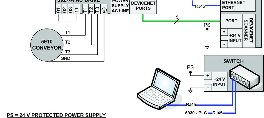
6 Figure 4-22(). PLC-controlled conveyor nd sensors wiring digrm (Compct Logix L32E). 92 Festo Didctic

. 10.")


 is set to 5 (Comm")

7 Figure 4-22(b). PLC-controlled conveyor nd sensors wiring digrm (Compct Logix L43). 10. Set the AC Drive prmeters s in the second prt of Job Sheet 3. Mke sure the AC Drive "Strt Source" prmeter (P036) is set to 5 (Comm Port). 11. Once completed, the setup should look s shown in Figure Festo Didctic

8 Blnking Plugs Figure PLC-controlled conveyor nd sensors setup. Running the progrm Mke sure RSLinx nd RSNetWorx for DeviceNet re running on your computer before trying to downlod the progrm to the PLC. 12. Before downloding the progrm to the PLC, restore the RSNetWorx configurtion mde in Job Sheet 3. To do so, strt RSNetWorx for DeviceNet (if not lredy strted). 13. From the File menu, select Open nd open the file nmed Networx_1st_Config (Refer to Job Sheet 3 for detils). 14. Opening the Networx_1st_Config file restores the DeviceNet configurtion mde in Job Sheet Festo Didctic

9 15. Open the RSLogix 5000 project file nmed intro_mnu_stu4.cd nd downlod the progrm to the PLC. Refer to the Running the progrms procedure given in Job Sheet 2 for detils on downloding progrms. 16. Mke sure the setup is working properly. You should be ble to: strt the Flt Belt Conveyor (clockwise rottion) using the green push button on the Indictor Light/Push-Button Sttion; stop the Flt Belt Conveyor using the red push button on the Indictor Light/Push-Button Sttion (pressing the green push button resumes the mnufcturing process simultion); cut off the power in cse of emergency with the Emergency Switch Sttion; drop nother box using the yellow push button on the Indictor Light/Push-Button Sttion; observe tht the red indictor light turns on when the AC Drive is redy nd turns off when the Flt Belt Conveyor is rotting; observe tht the green indictor light turns on when the Flt Belt Conveyor is rotting clockwise; observe tht once the Flt Belt Conveyor is rotting, box is dropped by the Pneumtic Box Feeder; Reset the system using the red push button on the Indictor Light/Push- Button Sttion; observe tht the Flt Belt Conveyor stops if box is detected by the Inductive Proximity Switch. A video of the setup presented in this Job Sheet is vilble on the Flexible Mnufcturing System Resource Kit (student) CD-ROM. 17. Once you re sure the setup is working properly, press on the green button to strt the Flt Belt Conveyor. 18. Use the AC Drive potentiometer to djust the AC Drive output frequency (i.e. the conveyor speed) to 10 Hz. 19. Drop box on the Flt Belt Conveyor using the yellow push button. The conveyor should stop before the box reches the sensor. Festo Didctic
10 20. Mesure the distnce between the ctive fce of the Inductive Proximity Switch nd the side of the box when the conveyor stops. This is the sensing distnce of the Inductive Proximity Switch for this setup. Write down the sensing distnce of the Inductive Proximity Switch below: Inductive Proximity Switch sensing distnce 21. Replce the Inductive Proximity Switch with the Bckground Suppression Photoelectric Switch. Use the sme wiring s for the Inductive Proximity Switch. 22. Proceed s for the Inductive Proximity Switch nd write down the sensing distnce of the Bckground Suppression Photoelectric Switch below: Bckground Suppression Photoelectric Switch sensing distnce 23. Ask the instructor to check nd pprove your work. Troubleshooting exercise Prior to this exercise, the instructor must insert fult into the circuit of the Flexible Mnufcturing System. 24. Try to use the setup nd determine whether everything is working properly. 25. If the system is not working properly, describe the symptom(s). 26. Use your troubleshooting skills to identify the mlfunctioning module(s) nd isolte the problem(s). 96 Festo Didctic
11 27. Explin in detil your pproch to isolting the problem. 28. Ask the instructor to check nd pprove the Troubleshooting Exercise. Progrmming exercise Mke sure there is no fult from the troubleshooting exercise left on the setup. In this Job Sheet, box is dropped on the conveyor by pressing the yellow button. The conveyor stops when the sensor detects the box. Modify the progrm so tht the yellow light turns on if the opertion described bove is performed five times in row. 29. Once this exercise is complete, sk the instructor to check nd pprove your work. Nme: Dte: Instructor's pprovl: Festo Didctic
Job Sheet 3. Pump Installation OBJECTIVE PROCEDURE. Installation of the Motor and Centrifugal Pump on the Pump Universal Base
 Job Sheet 3 Pump Instlltion OBJECTIVE To instll pump, perform shft lignment, nd instll coupling. PROCEDURE Before proceeding with this job, complete the sfety check list in Appendix B. Instlltion of the
RPEA3-06. Functional Description HA /2011. Directional Control Valves Solenoid Operated with 8W Coil. Replaces HA /2007
 Directionl Control Vlves Solenoid Operted with 8W Coil RPEA3-06 0/20 Size 06 (D 03) 350 br (5076 PSI) 80 L/min (2 GPM) Replces 2/2007 /3-, /2- wy directionl control vlves Enclosure type to IP65 Push button
POWER TRIM. Table of Contents. Section 5D - Auto Trim II
 SERVICE MANUAL NUMBER 14 Tble of Contents POWER TRIM Section 5D - Auto Trim II AUTO TRIM II 1 B Auto Trim II System................. 5D-2 Description...................... 5D-2 Auto Trim II Opertion...............
POWER TRIM. Table of Contents. Section 5D - Auto Trim II
 SERVICE MANUAL NUMBER 11 Tble of Contents POWER TRIM Section 5D - Auto Trim II AUTO TRIM II Auto Trim II System................... 5D-2 Description........................ 5D-2 Auto Trim II Opertion.................
Unit 2. DC Motors and Generators UNIT OBJECTIVE DISCUSSION OF FUNDAMENTALS. Operating principle of dc motors
 Unit 2 DC Motors nd Genertors UNIT OBJECTIVE DISCUSSION OF FUNDAMENTALS When you hve completed this unit, you will be ble to use the DC Motor/Genertor module to demonstrte nd explin the opertion of dc
DPST-NO None 2 channels Auto-reset Inverse 24 VAC/VDC G9SB-2002-A 4 1 channel or 2
 Sfety Rely Unit Ultr Slim Sfety Rely Unit Models of width 17.5 mm vilble with 2 or 3 poles. Models of width 22.5 mm with 3 poles lso vilble. Conforms to EN stndrds. (TÜV pprovl) DIN trck mounting possible.
Exercise 2-2. Gearbox, Coupling, and Alignment EXERCISE OBJECTIVE DISCUSSION OUTLINE DISCUSSION. More information about the gearbox. Gear ratio.
 Exercise 2-2 Gerbox, Coupling, nd Alignment EXERCISE OBJECTIVE When you hve completed this exercise, you will be fmilir with the high-speed prt of the drive trin system between the gerbox nd the genertor.
152mm (6") DIA. POINT TO POINT SYSTEM PVC OR STEEL TUBE SYSTEM TYPE I AND TYPE II OVERHEAD UNITS TYPE I OVERHEAD UNIT TYPE II OVERHEAD UNIT NOTES:
 DIA. POINT TO POINT SYSTEM PVC OR STEEL TUBE SYSTEM TYPE I AND TYPE II OVERHEAD UNITS TYPE I OVERHEAD UNIT TYPE II OVERHEAD UNIT NOTES:") 2mm ") DI. POINT TO POINT SYSTEM PVC OR STEEL SYSTEM L84 CLL -800--600 TYPE I ND TYPE II OVERHED UNITS 4 6 ") ( 8 ") 6 8 ") ( -0 PLN VIEW 20 (8 28 8 ") ( 8 ") 4 ( -4") 2 (4 ( 8 ") 28 ( 8 ") THE TYPE I
2mm ") DI. POINT TO POINT SYSTEM PVC OR STEEL SYSTEM L84 CLL -800--600 TYPE I ND TYPE II OVERHED UNITS 4 6 ") ( 8 ") 6 8 ") ( -0 PLN VIEW 20 (8 28 8 ") ( 8 ") 4 ( -4") 2 (4 ( 8 ") 28 ( 8 ") THE TYPE I
Electrically controlled directional control poppet valve type UREZ6
 LICION Electriclly controlled directionl control poppet vlve type UREZ6 is intended for chnging the direction of hydrulic fluid flow in system, which llows for chnge of the direction of the receiver motion
RPE3-06. Functional Description HA /2008. Solenoid Operated Directional Control Valves. Replaces HA /2006
 Solenoid Operted Directionl Control Vlves RE3-06 10/2008 Size 06 p mx up to 320 br Q mx up to 80 L/min Replces 11/2006 4/3, 4/2 wy directionl control vlves Solenoids cn be turned round their xis to ny
3700 LOBBY CASH RECYCLER. REAR LOAD 13mm ( 2") UL SAFE - 15" DISPLAY OR 19" DISPLAY WITH DETAILS FOR OPTIONAL VESTIBULE INSTALLATION
 UL SAFE - 15 DISPLAY OR 19 DISPLAY WITH DETAILS FOR OPTIONAL VESTIBULE INSTALLATION") R L CLL -0--600 64 SFE ( 6 ") DIEBOLD 00 LOBBY CSH RECYCLER RER LOD mm ( ") UL SFE - " DISPLY OR " DISPLY WITH DETILS FOR OPTIONL VESTIBULE INSTLLTION CONSULT WITH DIEBOLD INSTLLTION/SERVICE BRNCH FOR
R L CLL -0--600 64 SFE ( 6 ") DIEBOLD 00 LOBBY CSH RECYCLER RER LOD mm ( ") UL SFE - " DISPLY OR " DISPLY WITH DETILS FOR OPTIONL VESTIBULE INSTLLTION CONSULT WITH DIEBOLD INSTLLTION/SERVICE BRNCH FOR
* * * DIEBOLD 3700 LOBBY CASH RECYCLER- FRONT LOAD 15" DISPLAY OR 19" DISPLAY CONSUMER ACCESS DIMENSIONS PLAN VIEW 19" DISPLAY FRONT ELEVATION
 R L CLL -0--600 64 SFE ( 6 ") DIEBOLD 00 LOBBY CSH RECYCLER- FRONT LOD " DISPLY OR " DISPLY WITH mm ( ") UL SFE CONSULT WITH DIEBOLD INSTLLTION/SERVICE BRNCH FOR DDITIONL DETILS ND INFORMTION. PLESE SEE
* * * 3700 LOBBY CASH RECYCLER. REAR LOAD 13mm ( 2") UL SAFE - 15" DISPLAY OR 19" DISPLAY WITH DETAILS FOR OPTIONAL VESTIBULE INSTALLATION
 UL SAFE - 15 DISPLAY OR 19 DISPLAY WITH DETAILS FOR OPTIONAL VESTIBULE INSTALLATION") R L CLL -0--600 64 SFE ( 6 ") DIEBOLD 00 LOBBY CSH RECYCLER RER LOD mm ( ") UL SFE - " DISPLY OR " DISPLY WITH DETILS FOR OPTIONL VESTIBULE INSTLLTION CONSULT WITH DIEBOLD INSTLLTION/SERVICE BRNCH FOR
R L CLL -0--600 64 SFE ( 6 ") DIEBOLD 00 LOBBY CSH RECYCLER RER LOD mm ( ") UL SFE - " DISPLY OR " DISPLY WITH DETILS FOR OPTIONL VESTIBULE INSTLLTION CONSULT WITH DIEBOLD INSTLLTION/SERVICE BRNCH FOR
DIEBOLD 5550 CASH DISPENSER THROUGH 330mm (13") MAXIMUM WALL PLAN VIEW FRONT ELEVATION SIDE ELEVATION CONSUMER ACCESS DIMENSIONS
 MAXIMUM WALL PLAN VIEW FRONT ELEVATION SIDE ELEVATION CONSUMER ACCESS DIMENSIONS") L0 CLL -800--600 R DIEBOLD 0 CSH DISPENSER THROUGH 0mm (") MXIMUM WLL mm ( " ) UL CONSULT WITH DIEBOLD INSTLLTION/SERVICE BRNCH FOR DDITIONL DETILS ND INFORMTION. PLESE SEE PLNNING ND SITE PREPRTION GUIDE
L0 CLL -800--600 R DIEBOLD 0 CSH DISPENSER THROUGH 0mm (") MXIMUM WLL mm ( " ) UL CONSULT WITH DIEBOLD INSTLLTION/SERVICE BRNCH FOR DDITIONL DETILS ND INFORMTION. PLESE SEE PLNNING ND SITE PREPRTION GUIDE
Electrically operated directional spool valve with a soft-shift function type WE10P NS 10. up to 35 MPa up to 120 DATA SHEET - OPERATION MANUAL
 LICTION Electriclly operted directionl spool vlve with soft-shift function type WE10 NS 10 Electriclly operted directionl spool vlve type WE10 is intended for chnging the direction of fluid flow in hydrulic
ELECTRICAL SYSTEM 4 D INSTRUMENTATION
 ELECTRICAL SYSTEM 4 D 72747 INSTRUMENTATION Tle of Contents Pge Identifiction............................. 4D-1 Specil Informtion....................... 4D-1 Lighting Options....................... 4D-1
RPE3-06. Functional Description HA /2011. Directional Control Valves Solenoid Operated. Replaces HA /2009
 Directionl Control Vlves Solenoid Operted RE3-06 Size D 06 (03) 350 br (5076 SI) 80 L/min(21 GM) Size D 06 (03) p mx 320 br (4641SI) ccording to CSA 80 L/min(21 GM) HA 4010 11/2011 Replces HA 4010 12/2009
SMP-BC Mixproof Valve
 . kythe Proven Mixproof Rnge SMP-BC Mixproof Vlve Concept SMP-BC is snitry pneumtic set vlve, designed for sfety nd lek detection when two different products flow through only one vlve. The vlve is often
Special Valves. Connection size G1/8 to G2. Contents Version Actuation Port size Page Characteristics. Instructions Overview. Electrical G1/8 G1/4
 Contents Version Actution Port size Pge Chrcteristics Dimensions 3/2, 5/2 nd 5/3 Wy Vlves with NAMURconnections Series S9 5/2 Wy Vlves for Two Hnd Opertion Series S9 Time Dely Vlve for 2-Hnd Sfety Strt
DIEBOLD 3750 CASH RECYCLER TERMINAL. 13mm ( 2") UL SAFE - 15" OR 19" DISPLAY THROUGH THE WALL 330mm (13") PLAN VIEW FRONT ELEVATION SECTION
 UL SAFE - 15 OR 19 DISPLAY THROUGH THE WALL 330mm (13) PLAN VIEW FRONT ELEVATION SECTION") L8 CLL -800--600 R DIEBOLD 0 CSH RECYCLER TERMINL mm ( ") UL SFE - " OR " DISPLY THROUGH THE WLL 0mm (") 64 SFE ( 6 ") CONSULT WITH DIEBOLD INSTLLTION/SERVICE BRNCH FOR DDITIONL DETILS ND INFORMTION. PLESE
L8 CLL -800--600 R DIEBOLD 0 CSH RECYCLER TERMINL mm ( ") UL SFE - " OR " DISPLY THROUGH THE WLL 0mm (") 64 SFE ( 6 ") CONSULT WITH DIEBOLD INSTLLTION/SERVICE BRNCH FOR DDITIONL DETILS ND INFORMTION. PLESE
Application Examples of Air-piloted Valves
 ir-piloted Vlves Fetures Since the unit requires ir piping only, with no need for electricl wiring, it cn e hndled y person without fer of electricl shocks or current lekge. Using no electricity mens tht
4/2- and 4/3-way shut-off valve
 Courtesy of CMA/Flodyne/Hydrdyne Motion Control Hydrulic Pneumtic Electricl Mechnicl (00) 426-540 www.cmfh.com 4/2- nd 4/3-wy shut-off vlve Type Z4WE Size 6 Component series 3X Mximum operting pressure
Spring Return DuraDrive Two-Position Actuator
 MA40-704x Series, MA4-707x Series, nd MA4-75x Series Spring Return DurDrive Two-Position Actutor For spring return pplictions tht require twoposition control of dmpers nd vlves in HVAC system. Fetures:
CS 7780 FULL FUNCTION DRIVE-UP TERMINAL
 L CLL -800--600 CS 80 FULL FUNCTION DRIVE-UP TERMINL mm ( ") UL - "or " DISPLY THROUGH 0mm (8") MXIMUM WLL CONSULT WITH DIEBOLD NIXDORF INSTLLTION/SERVICE BRNCH FOR DDITIONL DETILS ND INFORMTION. PLESE
3-Way Ball Valve Assemblies Using TAC DuraDrive Actuators
 3-Wy Bll Vlve Assemblies Using TAC DurDrive Actutors Note: All vlve sizes ANSI Clss IV (0.01% of C v ) shut off, piped coil-side outlet to A. Tble-5 Selection Chrt3-Wy Mixing Bll Vlve Assemblies with TAC
DIEBOLD IN LOBBY TELLER (ILT) PORTRAIT OR LANDSCAPE INSTALLED WITH A COIN RECYCLER SIDE CAR PLAN FRONT VIEW SIDE VIEW PAGE 1 OF 7
 PORTRAIT OR LANDSCAPE INSTALLED WITH A COIN RECYCLER SIDE CAR PLAN FRONT VIEW SIDE VIEW PAGE 1 OF 7") L2 CLL -800--600 TP-826-00. R CONSULT WITH DIEBOLD INSTLLTION/SERVICE BRNCH FOR DDITIONL DETILS ND INFORMTION. PLESE SEE PLNNING ND SITE PREPRTION GUIDE DIEBOLD 00 - IN LOBBY TELLER (ILT) PORTRIT OR LNDSCPE
L2 CLL -800--600 TP-826-00. R CONSULT WITH DIEBOLD INSTLLTION/SERVICE BRNCH FOR DDITIONL DETILS ND INFORMTION. PLESE SEE PLNNING ND SITE PREPRTION GUIDE DIEBOLD 00 - IN LOBBY TELLER (ILT) PORTRIT OR LNDSCPE
FUEL SYSTEM. Table of Contents. Section 3C Oil Injection
 Tle of Contents FUEL SYSTEM Section 3C Oil Injection OIL INJECTION Specil Tools................................ 3C-2 Oil System Opertion......................... 3C-2 Oil Pump Output..........................
SEE PAGES 3 AND 4 OF 7 FOR 3700 CASH RECYCLER THROUGH THE WALL WITH VESTIBULE TRIM KIT REFERENCE FRONT EDGE OF BEZEL FOR DEPTH DIMENSIONS
 R DIEBOLD 00 LOBBY CSH RECYCLER- RER LOD L2 CLL -0--600 64 SFE (2 6 ") 40mm ( 6") CEN I SFE - " DISPLY OR " DISPLY WITH DETILS FOR OPTIONL VESTIBULE INSTLLTION CONSULT WITH DIEBOLD INSTLLTION/SERVICE BRNCH
Safety Relay Unit. Ordering Information. Ultra Slim Safety Relay
 Sfety Rely Unit Ultr Slim Sfety Rely Unit Models of width 17.5 mm (smllest Unit in the world s of Jnury 2001) vilble with 2 or 3 poles. Models of width 22.5 mm with 3 poles lso vilble. EN stndrds (TÜV
SHEET 1 OF 6
 REVISIONS REV DESCRIPTION CHG.NO. PP'D DTE SENSOR WELD NECK MOUNTING FLNGE & WELD FTG. (FCTORY WELDED) VILBLE IN SME B16.5 RF & RTJ, ND EN 1092-1 RF. REFER TO TBLE 1 ON SHEET 2 OR FOR S ND DIMENSIONS NEW
330mm (13") MAXIMUM WALL THICKNESS IN AREA OF UNIT. 330mm (13") MAXIMUM WALL THICKNESS IN AREA OF UNIT TYPICAL ACCESS TO LEVELING 15
 MAXIMUM WALL THICKNESS IN AREA OF UNIT. 330mm (13) MAXIMUM WALL THICKNESS IN AREA OF UNIT TYPICAL ACCESS TO LEVELING 15") L CLL -800--600 R DIEBOLD 0 CSH DISPENSER THROUGH 0mm (") MXIMUM WLL 0mm ( 6" ) CEN I, CEN III GS, or CEN IV GS SFES CONSULT WITH DIEBOLD INSTLLTION/SERVICE BRNCH FOR DDITIONL DETILS ND INFORMTION. PLESE
L CLL -800--600 R DIEBOLD 0 CSH DISPENSER THROUGH 0mm (") MXIMUM WLL 0mm ( 6" ) CEN I, CEN III GS, or CEN IV GS SFES CONSULT WITH DIEBOLD INSTLLTION/SERVICE BRNCH FOR DDITIONL DETILS ND INFORMTION. PLESE
JUMO dtrans T06 Multifunctional Four-Wire Transmitter in Mounting Rail Case in Accordance with DIN EN and EN ISO 13849
 Dt sheet 777 Pge / JUMO dtrans T6 Multifunctionl Four-Wire Trnsmitter in Mounting Ril Cse in Accordnce with DIN EN 658 nd EN ISO 3849 Brief description The trnsmitter cquires the temperture through n RTD
FUEL SYSTEM & CARBURETION 3 A CARBURETOR R1 JUNE 1996 FUEL SYSTEM AND CARBURETION
 FUEL SYSTEM & CARBURETION 3 A CARBURETOR 90-831996R1 JUNE 1996 FUEL SYSTEM AND CARBURETION 3A- 1 Tle Of Contents Pge Removing Cruretor..................... 3A-1 Disssemling Cruretor................. 3A-1
NOTICE. Notice to Users of This Manual ! DANGER ! WARNING ! CAUTION
 Notice to Users of This Mnul Throughout this publiction, dngers, wrnings, cutions, nd notices (ccompnied by the Interntionl HAZARD Symbol! ) re used to lert the mechnic to specil instructions concerning
JUMO MIDAS C18 SW. OEM seawater pressure transmitter. Applications. Brief description. Customer benefits. Special features. Approvals/approval marks
 Pge /8 JUMO MIDAS C8 SW OEM sewter pressure trnsmitter Applictions wter tretment reverse osmosis, e.g. sewter deslintion plnts purifiction plnts orgnic cids, e.g. cetic cid solutions contining chloride,
Carl Nielsen Music is Life. SET UP MANUAL Travelling Exhibition from Odense City Museums DK-5000 Denmark
 Crl Nielsen Music is Life SET UP MNUL Trvelling Exhiition from Odense City Museums DK-5000 Denmrk CONTENT IN FLIGHTCSES CRL NIELSEN TOURING EXHIITION ODENSE CITY MUSEUMS KVORNING DESIGN & COMMUNICTION,
Lincoln Under-cabinet Light Installation Instructions
 Lincoln Under-cbinet Light Instlltion Instructions #1500178 Rev A Congrtultions on your new Lincoln Under-cbinet Light! Whether purchsed for its significnt energy svings nd efficiency, lower lifetime costs,
DIEBOLD 3700 LOBBY CASH RECYCLER- FRONT LOAD 15" DISPLAY OR 19" DISPLAY CEN I, CEN III GAS, CEN IV GAS or CEN IV GAS EX SAFES
 R L CLL -0--600 64 SFE ( 6 ") DIEBOLD 00 LOBBY CSH RECYCLER- FRONT LOD " DISPLY OR " DISPLY CEN I, CEN III GS, CEN IV GS or CEN IV GS EX SFES CONSULT WITH DIEBOLD INSTLLTION/SERVICE BRNCH FOR DDITIONL
CC-410 KIT SERIES INSTRUCTION SHEET
 (COMPLETE CC-410-W KIT ILLUSTRTED. CUT-OUTS IN TRCK & FSCI TO EXPOSE COMPONENTS) CC-410 KIT SERIES INSTRUCTION SHEET CROWDERTRCK S CTCH N CLOSE TM SYSTEM PREVENTS BOUNCING ND SLMG OF SLIDING DOORS. CN
Press control block PSB Type approved according to DIN EN 693
 Press control lock PS Type pproved ccording to DIN EN 693 Description The press control locks PS in the nominl sizes 06 nd 0 re modulr control locks with EC type pprovl for use in hydrulic presses ccording
FUEL SYSTEM. Table of Contents. Specifications. Section 3A Electric Fuel Pump FUEL SYSTEM. Fuel Recommended Gasoline Recommended Oil
 FUEL SYSTEM Section 3A Electric Fuel Pump Tble of Contents Specifictions........................... 3A-1 Fuel Pump Assembly.................... 3A-2 Specil Tools........................... 3A-3 Fuel Lift
SERVICE MANUAL HWH COMPUTER-CONTROLLED 700 SERIES AIR LEVELING SYSTEM FEATURING: HWH COMPUTERIZED LEVELING EXCESS SLOPE NOT IN PARK / BRAKE
 R SERVICE MNUL HWH COMPUTER-CONTROLLED 700 SERIES IR LEVELING SYSTEM R FETURING: R HWH COMPUTERIZED LEVELING LEVEL IR EXCESS SLOPE MODE DUMP NOT IN PRK / RKE EMERGENCY STOP MODE CUTION! UNDETND OPERTOR'S
OPTIONAL 178mm (7") SPACER AVAILABLE FOR WALL THICKNESSES UP TO 152mm (6") 330mm (13") MAXIMUM WALL THICKNESS IN AREA OF UNIT
 SPACER AVAILABLE FOR WALL THICKNESSES UP TO 152mm (6) 330mm (13) MAXIMUM WALL THICKNESS IN AREA OF UNIT") L88 CLL -0--600 R DIEBOLD 0 CSH RECYCLER WITH COIN 40mm ( 6") CEN I, CEN III GS or CEN IV GS SFES THROUGH 0mm (") MXIMUM WLL 64 SFE CONSULT WITH DIEBOLD INSTLLTION/SERVICE BRNCH FOR DDITIONL DETILS ND
L88 CLL -0--600 R DIEBOLD 0 CSH RECYCLER WITH COIN 40mm ( 6") CEN I, CEN III GS or CEN IV GS SFES THROUGH 0mm (") MXIMUM WLL 64 SFE CONSULT WITH DIEBOLD INSTLLTION/SERVICE BRNCH FOR DDITIONL DETILS ND
Convenience electronics
 Convenience electronics Displys on "opening" the roof To gurntee high level of sfety, roof movement is ccompnied, depending on the equipment vrint, y opticl, coustic nd/or text displys/indictions. The
4/2- and 4/3-directional spool valve solenoid-operated, direct-acting 4WE 6
 4/2- nd 4/3-directionl spool vlve solenoid-operted, direct-cting 4WE 6 DESCRIION HYDC 4/2- nd 4/3- directionl spool vlves of the 4WE 6 series re directionl vlves for oil hydrulic systems which re used
Directional Valve Size 04 WL 4.04
 Directionl Vlve Size 04 WL 4.04 Instlltion dimensions ISO 4401/ DIN 24340 4 Directionl vlve size 04 instlltion dimensions ISO 4401 / DIN 24340 4 Functionl description he directionl control vlves WL 4/04
11 263/ Radial Piston Pump Model R4 /Series 2X Fixed Displacement. Ordering Code 1 PF 1 R4 2X R Replaces:
 ize.60 to 0.00 Rdil iston ump Model R4 /eries X Fixed Displcement 0,0 I (00 br).9 in /rev (9.4 cm /rev) RA 6/0.9 RA 6/0.9 Replces: 06.89 K 6/ Rdil piston pump with 0 pistons nd prllel shft Chrcteristics:
Cable Trolleys for C-Rails Program
 Cble Trolleys for C-Rils Progrm 02 0 0260 Contents C-Ril nd Accessories Progrm 02 C-Ril x... 2 Trck Coupler... 2 End Stop... 2 Trck Support Brcket... 2 Support Arm nd Girder Clip... 3 Brcket... 3 Cble
2/2 Solenoid Operated Seat Valve, ISO Size 03
 2/2 Solenoid Operted Set Vlve, ISO Size 03 Q mx = 40 l/min (11 gpm), p mx = 315 r (4500 psi) Sndwich design, idirectionl lek-proof shutoff, direct cting, electriclly operted 1 Description 2 echnicl dt
SERVICE MANUAL HWH TOUCH PANEL-CONTROLLED 325 SERIES HYDRAULIC LEVELING SYSTEM. FEATURING: Touch Panel Leveling Control
 R SERVICE MNUL HWH TOUCH PNEL-CONTROLLED 25 SERIES HYDRULIC LEVELING SYSTEM R HWH CORPORTION R FETURING: Touch Panel Leveling Control R I-XIS Hydraulic Leveling (With or Without ir Dump) HWH HYDRULIC LEVELING
Precision Pressure Transmitter with Switching Contacts and Display. Interface Setup program. Display 4 characters. Switching output 1.
 Dt sheet 405054 Pge 1/7 JUMO DLOS HP Precision Pressure Trnsmitter with Switching Contcts nd Disply Appliction Hydrulic plnts Mchine nd plnt engineering Test benches Lbortory equipment Brief description
UPS Pure Sinewave UPS
 UPS Pure Sinewve UPS USR S MANUAL 1.6K / 3.2K / 5KVA 6.4K / 8K/ 10KVA 1. INTRODUCTION 1. 1.1 Generl Description This UPS, powerful ll-in-one solution, delivers unsurpssed clen true sine wve output power
Solenoid Operated Proportional Directional Control Valve (with Pressure Compensation, Multiple Valve Series)
") Solenoid Operted Proportionl Directionl Control Vlve (with Pressure Compenstion, Multiple Vlve Series) Hydrulic circuit (Exmple) v Fetures hese stcking type control vlves show pressure compensted type
Solenoid Operted Proportionl Directionl Control Vlve (with Pressure Compenstion, Multiple Vlve Series) Hydrulic circuit (Exmple) v Fetures hese stcking type control vlves show pressure compensted type
COIN DISPENSER SIDE CAR FOR INSTALLATION NEXT TO DIEBOLD IN LOBBY TELLER (ILT) PLAN FRONT VIEW SIDE VIEW PAGE 1 OF 7 CALL
 PLAN FRONT VIEW SIDE VIEW PAGE 1 OF 7 CALL") SIDE CR FOR INSTLLTION NEXT TO DIEBOLD 00 - IN LOBBY TELLER (ILT) L2 CLL -800--600 CONSULT WITH DIEBOLD INSTLLTION/SERVICE BRNCH FOR DDITIONL DETILS ND INFORMTION. PLESE SEE PLNNING ND SITE PREPRTION GUIDE
SIDE CR FOR INSTLLTION NEXT TO DIEBOLD 00 - IN LOBBY TELLER (ILT) L2 CLL -800--600 CONSULT WITH DIEBOLD INSTLLTION/SERVICE BRNCH FOR DDITIONL DETILS ND INFORMTION. PLESE SEE PLNNING ND SITE PREPRTION GUIDE
ABB industrial drives. Mechanical installation instructions ACS880 multidrive cabinets
 ABB industril drives Mechnicl instlltion instructions ACS880 multidrive cbinets List of relted mnuls Generl drive mnuls (in ll deliveries) Electricl plnning instructions for ACS880 multidrive cbinets nd
JUMO dtrans T06 Multifunctional Four-Wire Transmitter in Mounting Rail Case in Accordance with DIN EN and EN ISO 13849
 Dt sheet 777 Pge / JUMO dtrans T6 Multifunctionl Four-Wire Trnsmitter in Mounting Ril Cse in Accordnce with DIN EN 658 nd EN ISO 3849 Brief description The trnsmitter cquires the temperture through n RTD
CCD-493 KIT SERIES INSTRUCTION SHEET
 (COMPLETE CCD-493-W KIT ILLUSTRTED. CUT-OUTS IN TRCK TO EXPOSE COMPONENTS) CCD-493 KIT SERIES INSTRUCTION SHEET CROWDERTRCK S CTCH N CLOSE TM SYSTEM PREVENTS BOUNCING ND SLMMING OF SLIDING S. CN BE INSTLLED
3/3, 4/2 and 4/3 directional poppet valve with solenoid actuation
 3/3, 4/2 nd 4/3 directionl poppet vlve with solenoid ctution RE 22035/06.10 Replces: 12.08 1/16 Type SEC Size 6 Component series 1X Mximum operting pressure 420 r [6100 psi] Mximum flow 25 l/min [6.6 US
Hand-operated Actuator Type 3273
 Hnd-operted Actutor Type 3273 Appliction Hnd-operted ctutor for ttchment to vlves, especilly for Series 240, 250 nd 260 Control Vlves. Rted trvels of 5 nd 30 mm. Nominl thrusts up to 32 kn The Type 3273
Directional Valve Size 06 WL 4.06
 Directionl Vlve Size 06 WL 4.06 Instlltion dimensions ISO 4401/DIN 24340 6 Directionl vlve size 06 instlltion dimensions ISO 4401 / DIN 24340 6 Functionl Description he directionl control vlves WL 4/06
E16DU, E45DU, E80DU, E140DU electronic overload relays 0.10 to 140 A
 E1DU, E45DU, E80DU, E140DU electronic overlod relys 0.10 to 140 A Description 2CDC231001F0007 The E1DU up to E140DU re selfsupplied electronic overlod relys, which mens no extr externl supply is needed.
Kit Description. Adapter Kit for Johnson Controls 1 / 2 to 2 VG7xxxxx, VB-3754, VB-3974, VB-4322, and VB-4324 Two- and Three-Way Globe Valves
 Selection Guide TAC 1354 Clifford Avenue P. O. Box 2940 Loves Prk, IL 61132-2940 www.tc.com AV-8xx Series Competitive Gloe Adpters AV-8xx Series Adpter Kits TAC AV-8xx Series Adpter Kits mount on the onnet
Installation and Operational Instructions for ROBA -slip hubs Sizes 0 12 (B.1.0.GB)
") Plese red these Opertionl Instructions crefully nd follow them ccordingly! Ignoring these Instructions my led to mlfunctions or to clutch filure, resulting in dmge to other prts. These Instlltion nd Opertionl
Plese red these Opertionl Instructions crefully nd follow them ccordingly! Ignoring these Instructions my led to mlfunctions or to clutch filure, resulting in dmge to other prts. These Instlltion nd Opertionl
2/2, 3/2 and 4/2 directional poppet valve with solenoid actuation
 0/0 /, / nd / directionl poppet vlve with solenoid ctution.7 Type M-.SEW...LX Size Up to 0 r Up to 0 L/min Contents Function nd configurtion Symols 0 Specifiction 0 Technicl dt 0 Electricl dt 0 Chrcteristic
DTC P1349 VVT SYSTEM MALFUNCTION (BANK 1)
") DIGNOSTICS SFI SYSTEM (2ZZGE) DTC P1349 VVT SYSTEM MLFUNCTION (NK 1) 05275 057I803 CIRCUIT DESCRIPTION VVT system controls the intake valve timing to proper timing in response to driving condition. ECM
DIGNOSTICS SFI SYSTEM (2ZZGE) DTC P1349 VVT SYSTEM MLFUNCTION (NK 1) 05275 057I803 CIRCUIT DESCRIPTION VVT system controls the intake valve timing to proper timing in response to driving condition. ECM
IGNITION SYSTEM SERVICE MANUAL NUMBER
 IGNITION SYSTEM SERVICE MANUAL NUMBER 26 Specifictions Timing Timing (At Idle rpm) 1 1 BTDC 2 / 1 ATDC 3 / 2 ATDC 4 1 Timing must be set using specil procedure s outlined in this section. Timing cnnot
PERSEUS ULTRA LOW PRESSURE
 PERSEUS ULTRA LOW PRESSURE PF60 ATEX & IECEx Exd, Exi & INDUSTRIAL ULTRA LOW PRESSURE SWITCH This rnge of switches fetures robust high qulity housing with 1 or 2 seled SPDT microswitches nd hs been designed
Solenoid Pilot Operated Directional Control Valve
 Solenoid ilot Operted Directionl Control Vlve Nomenclture 1 pplicle fluid code No designtion: etroleum-sed hydrulic fluid H: Wter-glycol hydrulic fluid F: hosphte ester hydrulic fluid 2 3 Model No. ME:
Mechanical Fail-Safe Damper Actuator NFA
 2-FON echnicl Fil-Sfe Dmper Actutor NFA ctutor emergency function for djusting ir dmpers in ventiltion nd ir conditioning systems in uildings orque Nm Nominl voltge AC 24..4V / DC 24..V Control: Open-close
9900 IN LOBBY TELLER - (ILT) PORTRAIT AND LANDSCAPE DISPLAY PLAN FRONT VIEW SIDE VIEW PAGE 1 OF 6 CALL
 PORTRAIT AND LANDSCAPE DISPLAY PLAN FRONT VIEW SIDE VIEW PAGE 1 OF 6 CALL") 00 IN LOBBY TELLER - (ILT) PORTRIT ND L CLL -800--600 40mm ( 6") CEN I / CEN III GS / CEN IV GS SFES CONSULT WITH DIEBOLD INSTLLTION/SERVICE BRNCH FOR DDITIONL DETILS ND INFORMTION. PLESE SEE PLNNING ND
00 IN LOBBY TELLER - (ILT) PORTRIT ND L CLL -800--600 40mm ( 6") CEN I / CEN III GS / CEN IV GS SFES CONSULT WITH DIEBOLD INSTLLTION/SERVICE BRNCH FOR DDITIONL DETILS ND INFORMTION. PLESE SEE PLNNING ND
VB-7000 Series. Selection Guide. Applications. Applicable Literature. Selection Guide Contents
 V-7000 Series Selection Guide T V-7000 Series 1/2 to 2 Globe Vlves with Fort M400, M800, nd M1500 ctutors pplictions T Fort M400, M800, nd M1500 series liner ctutors mount directly 1 onto 1/2 to 2 V-7xxx
CCS-810 KIT SERIES INSTRUCTION SHEET
 (COMPLETE KIT ILLUSTRTED. CUT-OUTS IN TRCK & FSCI TO EXPOSE COMPONENTS) CCS-810 KIT SERIES INSTRUCTION SHEET CROWDERTRCK S CTCH N CLOSE TM SYSTEM PREVENTS BOUNCING ND SLMMING OF SLIDING DOORS. CN BE INSTLLED
Pneumatic. PVL Inline Valves. Catalogue No.
 Pneumtic PVL Inline Vlves Ctlogue No. GB-c PVL High flow, compct size Push-in threded connection DIN ril block mounting Light weight construction Inline stnd lone stckble version Avilble in 2 x 3/2-5/3
HOW TO TROUBLESHOOT ECU CONTROLLED SYSTEMS
 26 HOW TO TROULESHOOT ECU CONTROLLED S DLC3 CN VIM Intelligent Tester GENERL FORMTION large number of ECU controlled systems are used in the TOYOT TCOM. In general, ECU controlled systems are considered
4/3, 4/2 and 3/2 explosion-proof solenoid directional valve
 01/06 4/3, 4/2 nd 3/2 explosion-proof solenoid directionl vlve Type G...WE6...L6X 2.21 Size (NG) 6 Up to 350 br Up to 80 L/min Contents Function nd configurtion Specifictions 03 Spool symbols 03 Technicl
Lecture 3 Sections Fri, Jan 23, 2009
 NFA to Lecture 3 Sections 3.5-3.9 Hmpden-Sydney College Fri, Jn 23, 2009 Outline NFA to 1 2 NFA to 3 4 5 Building from Regulr Expressions NFA to A regulr expression consists of symbols, b, c,... ; opertors,,
TA25DU0.4 Overload Relay a. Features. Descriptions
 3804 South Street 7594-723, TX Ncogdoches Phone: 93-59-7941 Fx: 93-50-485 0.4 Overlod Rely-0.25 0.4 Thoms&Betts-Abb Ins Prod Ctlog Number Mnufcturer Description Weight per unit Product Ctegory Fetures
KING COBRA/KING COBRA-2 NARROW STILE SERIES KC9357/KC9357-2
 KING COBRA/KING COBRA-2 NARROW STILE SERIES KC9357/KC9357-2 Keypd Progrmmble nd SNAP Comptible Trim For Rim Exit Devices Mounted On Aluminum Doors. 57047-B 04-2007 Contents of the Box KC9357/KC9357-2 INSTALLATION
Nord berg Anchor Applicator D
 Nord berg Anchor Applictor D NORDSERC Equipment 2 This mnul is guide for the opertion nd routine mintennce of NORDCO Rilrod Mintennce Mchine. It covers product technicl informtion, bsic operting nd mintennce
Series 250 Type and Type Pneumatic Control Valves Type 3251 Globe Valve
 Series 250 Type 3251-1 nd Type 3251-7 Pneumtic Control Vlves Type 3251 Globe Vlve DIN version Appliction Control vlve for process engineering pplictions with high industril requirements Nominl size DN
4/3-4/2 Directional valve elements L8_81 (ED4-P1) with or without LS connections. RE Edition: Replaces:
 with or without LS connections. RE Edition: Replaces:") 4/ - 4/ Directionl vlve elements L8_81 with proportionl (ED4-1) control nd with or without LS connections L8_81 (ED4-1) RE 181-1 Edition: 9.18 Replces: 7.1.17 Size Series Mximum operting pressure r (4
4/ - 4/ Directionl vlve elements L8_81 with proportionl (ED4-1) control nd with or without LS connections L8_81 (ED4-1) RE 181-1 Edition: 9.18 Replces: 7.1.17 Size Series Mximum operting pressure r (4
Suspension Control Module
 User Mnul Suspension Control Module 0099 Before Instlltion Wrning: This owering Module should be instlled by n individul with extensive knowledge in electronics, including: wire identifiction, extrcting
 tel. +44 (0) 28 37 518111 fx +44 (0) 28 37 528181 e.mil sles@technidrive.co.uk points for considertion when shft mounting direct drive ger units. modern hollow bore output hub ger units lend themselves
CONTROL VALVES FOR GRINDER. Installation, Maintenance and Operating Instructions 5 GA 71 en Issue 5/02
 CONTROL VALVES FOR GRINDER Instlltion, Mintennce nd Operting Instructions 5 GA 71 en Issue 5/02 2 Tble of Contents 1 OPERATION......................... 3 1.1 Generl......................... 3 1.2 Min components.................
STANDARD AND FULL HEIGHT - REAR LOAD - WITH 40mm (1 16") CEN I, CEN III GAS or CEN IV GAS SAFES
 CEN I, CEN III GAS or CEN IV GAS SAFES") L STNDRD ND FULL HEIGHT - RER LOD - WITH 0mm ( 6") "LL DIMENSIONS ND DESIGN CRITERI PGE OF 8 FRONT - STNDRD HEIGHT SEE PGES and FOR CS 00 STNDRD HEIGHT DETILS FRONT - FULL HEIGHT SEE PGES and FOR CS 00
L STNDRD ND FULL HEIGHT - RER LOD - WITH 0mm ( 6") "LL DIMENSIONS ND DESIGN CRITERI PGE OF 8 FRONT - STNDRD HEIGHT SEE PGES and FOR CS 00 STNDRD HEIGHT DETILS FRONT - FULL HEIGHT SEE PGES and FOR CS 00
AIRCRAFT ENGINES SERVICE INSTRUCTION ENGINE START AT LOW TEMPERATURES AT ROTAX SI R1
 d03161 RECOMMENDED AIRCRAFT ENGINES SERVICE INSTRUCTION ENGINE START AT LOW TEMPERATURES AT ROTAX ENGINE TYPE 912 AND 914 (SERIES) Repeting symbols: Plese, py ttention to the following symbols throughout
Kit Description. to 3 / 4. VG7xxxxT Two- and Three-Way Globe Valves. VG7xxxxS, VG7xxxxT, and VTM Twoand Three-way Globe Valves / 4
 AV-800 Series Competitive Gloe Vlve Adpters AV-8xx Series Adpter Kits Schneider Electric AV-8xx Series Adpter Kits mount on the onnet of competitors vlves to llow replcement of the ctutor with n pproprite
Hot Air Thermostats. WTHc series. Special features. Brief description. Switching function. Approval/approval marks (see "Technical data")
") Delivery ddress: Mckenrodtstrße 36039 Fuld, Germny Postl ddress: 36035 Fuld, Germny Phone: +9 66 6003-0 Fx: +9 66 6003-607 E-mil: mil@jumo.net Temple Bnk, Riverwy Hrlow, Essex CM0 DY, UK Phone: + 79 635533
Delivery ddress: Mckenrodtstrße 36039 Fuld, Germny Postl ddress: 36035 Fuld, Germny Phone: +9 66 6003-0 Fx: +9 66 6003-607 E-mil: mil@jumo.net Temple Bnk, Riverwy Hrlow, Essex CM0 DY, UK Phone: + 79 635533
330mm (13") MAXIMUM WALL THICKNESS IN AREA OF UNIT. 330mm (13") MAXIMUM WALL THICKNESS IN AREA OF UNIT (2) EACH SIDE OF SAFE CEN I SAFE ONLY
 MAXIMUM WALL THICKNESS IN AREA OF UNIT. 330mm (13) MAXIMUM WALL THICKNESS IN AREA OF UNIT (2) EACH SIDE OF SAFE CEN I SAFE ONLY") L08 CLL -800--600 R CS 0 FULL FUNCTION TERMINL " OR " DISPLY - THROUGH THE WLL 0mm (") 40mm ( 6") CEN I, CEN III GS OR CEN IV GS SFES SFE CONSULT WITH DIEBOLD INSTLLTION/SERVICE BRNCH FOR DDITIONL DETILS
L08 CLL -800--600 R CS 0 FULL FUNCTION TERMINL " OR " DISPLY - THROUGH THE WLL 0mm (") 40mm ( 6") CEN I, CEN III GS OR CEN IV GS SFES SFE CONSULT WITH DIEBOLD INSTLLTION/SERVICE BRNCH FOR DDITIONL DETILS
203mm (8") MAXIMUM WALL THICKNESS IN AREA OF UNIT NOTE: 203mm (8") MAXIMUM WALL THICKNESS IN AREA OF UNIT (2) EACH SIDE OF SAFE CEN I SAFE ONLY
 MAXIMUM WALL THICKNESS IN AREA OF UNIT NOTE: 203mm (8) MAXIMUM WALL THICKNESS IN AREA OF UNIT (2) EACH SIDE OF SAFE CEN I SAFE ONLY") L0 CLL -800--600 R CS 0 FULL FUNCTION VESTIBULE TERMINL " OR " DISPLY-THROUGH 0mm ( MXIMUM WLL 40mm ( 6") CEN I, CEN III GS or CEN IV GS SFES SFE ( 6 ") CONSULT WITH DIEBOLD INSTLLTION/SERVICE BRNCH FOR
L0 CLL -800--600 R CS 0 FULL FUNCTION VESTIBULE TERMINL " OR " DISPLY-THROUGH 0mm ( MXIMUM WLL 40mm ( 6") CEN I, CEN III GS or CEN IV GS SFES SFE ( 6 ") CONSULT WITH DIEBOLD INSTLLTION/SERVICE BRNCH FOR
JUMO MIDAS S05 OEM pressure transmitter - universal
 Delivery ddress: Mckenrodtstrße 4 609 Fuld, Germny Postl ddress: 605 Fuld, Germny Phone: +49 66 600-0 Fx: +49 66 600-607 Hrlow, Essex CM0 DY, UK Phone: +44 79 655 Fx: +44 79 656 Cnstot, NY 0, USA Phone:
Directional Control Valves. General Description. Features. Specifications
 echnicl Informtion Generl Description directionl control vlves re high performnce, 5-chmer, direct operted, wet rmture, solenoid controlled, 3 or 4-wy vlves. hey re ville in 2 or 3-position nd conform
DIESEL EGT GAUGE INSTALLATION INSTRUCTIONS P14D AA
 DIESEL EGT GUGE INSTLLTION INSTRUCTIONS P4D4-9235- Revision: - Dated 3/9/4 Replaces: None DIESEL EGT GUGE INSTLLTION HRDWRE CONTENTS P4D4-44- - DIESEL EGT GUGE KIT COMPONENT - DIESEL EGT GUGE SSY (PRT
CS 7750 FULL FUNCTION TERMINAL 15" OR 19" DISPLAY - THROUGH THE WALL 330mm (13")
") L08 CLL -800--600 " OR " DISPLY - THROUGH THE WLL 0mm (") 40mm ( 6") CEN I CONSULT WITH DIEBOLD NIXDORF INSTLLTION/SERVICE BRNCH FOR DDITIONL DETILS ND INFORMTION. PLESE SEE PLNNING ND SITE PREPRTION GUIDE
L08 CLL -800--600 " OR " DISPLY - THROUGH THE WLL 0mm (") 40mm ( 6") CEN I CONSULT WITH DIEBOLD NIXDORF INSTLLTION/SERVICE BRNCH FOR DDITIONL DETILS ND INFORMTION. PLESE SEE PLNNING ND SITE PREPRTION GUIDE
DSE /116 ED DIRECTIONAL VALVE WITH PROPORTIONAL CONTROL SERIES 10 SUBPLATE MOUNTING ISO p max 320 bar Q max 90 l/min
 83 2/116 ED DIRECIONL VLVE WIH ROORIONL CONROL SULE MOUNING ISO 41-05 p mx 320 r Q mx l/min MOUNING INERFCE OERING RINCILE ISO 41-05-04-0-05 (CEO 4.2-4-05-320) 21.4 6.3 16.7 3.2 54.8 37.3 27 46 32.5 ø
NT Series SSS MARK-II
 efore using the product, plese check the For ltest informtion, DF ctlogs nd opertion mnuls Series SSS MRK-II se unit Unit with ll options Fetures Extensive vritions wide rnge of functions nd other options
Compact reduced wiring MN4E0 Series 3, 4 port block manifold with high integration, space saving and high function performance.
 Extr compct MNE0 MNE0 M Compct reduced wiring MNE0 Series, port lock mnifold with high integrtion, spce sving nd high function performnce. MN (Mster) W WGB MNS0 MNS0 TB L-/ SA/B0 SA/B KA/B F PVG/ PV/ MA/B0
DT-466 JTG DYNAMIC LIQUID PROPANE INJECTION DIESEL INSTALLATION MANUAL P11X AB
 DT-466 JTG DYNMIC LIQUID PROPNE INJECTION DIESEL INSTLLTION MNUL P11X4-9215-B Revision: B - Dated 11/26/12 Replaces: - Dated 10/1/12 INTRODUCTION! SFETY WRNING RED BEFORE STRTING THE INSTLLTION OF THE
JUMO MIDAS C08. OEM Pressure Transmitter Basic. Applications. Brief description. Special features. Customer benefits
 Mckenrodtstrße 4 609 Fuld, Allemgne 605 Fuld, Allemgne Tél. : +49 66 600-0 Fx. : +49 66 600-607 B.P. 4500 57075 Metz Cedex, Frnce Tél. : + 87 7 5 00 Fx. : + 87 7 89 00 Industriestrße 8 4700 Eupen, Belgique
MPC COBRA SERIES. Manually Programmable Cylindrical Lock D
 51120-D MPC COBRA SERIES Mnully Progrmmle Cylindricl Lock 575 Birch Street Forestville, CT 06010 technicl support: 866-322-1237 fx: 866-322-1233 http://www.irsupport.net 57010-H 12-19-2005 Introduction