Index Flow Sensors FLOWX3 F3.00 Paddlewheel Flow Sensor page 2 FLOWX3 F111 Hot Tap Flow Sensor page 18 FLOWX3 F3.60M Insertion Magmeter page 24 FLOWX3
|
|
|
- Theresa Dennis
- 5 years ago
- Views:
Transcription

1 09-10 LEFLSFX10
2 Index Flow Sensors FLOWX3 F3.00 Paddlewheel Flow Sensor page 2 FLOWX3 F111 Hot Tap Flow Sensor page 18 FLOWX3 F3.60M Insertion Magmeter page 24 FLOWX3 F9.60M Insertion Magmeter with display page 30 FLOWX3 F3.61M Hot Tap Insertion Magmeter page 36 FLOWX3 F3.11.H.BD Bi-directional Turbine Flow Sensors page 40 FLOWX3 ULF Ultra Low Flow Sensor page 44 FLOWX3 F3.80 Oval Gear Flow Sensor page 54 FLOWX3 F3.05 Paddlewheel Flow Switch page 58 FLOWX3 F3.10 Paddlewheel Mini Flow Sensor page 64 Instrumentation FLOWX3 F9.00 Flow Monitor & Transmitter page 68 FLOWX3 F9.00.BD Bi-directional Flow Monitor and Transmitter page 82 FLOWX3 F9.20 Battery Powered Flow Monitor page 88 FLOWX3 F9.20.BD Bi-directional Battery Powered Flow Monitor page 96 FLOWX3 F9.50 Batch Controller page 100 Accessories 24VDC Single Phase Switching Power Supply page 112 F.IMSP1 Interface Module Sensor PLC page 113 Installation Fittings Installation Fittings for Paddlewheel and Electromagnetic Flow Sensors page 114 Technical Information Insertion Technology Main Features page 128 Conversion Tables page 131 Assistance Application Form page 134 All technical and commercial information contained in this catalogue are subject to change without notice and FIP - FLS does not guarantee about their thoroughness. 1
 producing a frequency output signal highly repeatable. A rugged construction and a proven technology guarantee exceptional performances with little or no maintenance required.")
3 FLOWX3 F3.00 Paddlewheel Flow Sensor F3.00 The simple and reliable paddlewheel flow sensor type F3.00 is designed for use with every kind of solid-free liquids. The sensor can measure flow from 0.15 m/s (0.5 ft/s) producing a frequency output signal highly repeatable. A rugged construction and a proven technology guarantee exceptional performances with little or no maintenance required. A new electronic, with a push-pull output, is now available for a safe connection to any kind of PLC/Instrument digital input. A specially designed family of fittings ensures an easy and quick installation into all pipe materials in sizes from DN15 to DN600 (0.5" to 24"). Main Features n CPVC, PVDF, Brass or Stainless Steel sensor body. n Easy insertion system. n Different versions for remote and compact installations. n Measurement range over 50:1. n High chemical resistance. n Battery powered version. n 4-20 ma output. n MIN alarm relay output. n Push-Pull output for universal electrical connection. Applications n Water treatment and regeneration. n Industrial wastewater treatment and recovery. n Textile finishing. n Water distribution. n Processing and manufacturing industry. n Filtration systems. n Chemical production. n Liquid delivery systems. n Cooling water monitoring. n Heat Exchangers. n Swimming pools. n Pump protection. Technical Features Sensor for compact installation (F3.01) with field-mount transmitter (sold separately) Sensor for remote installation in IP68 configuration Sensor for remote installation in IP65 configuration Paddlewheel system 1) Electrical cable: 8 m. (26.4 ft) standard 2) 4 pole cable plug according to DIN B/ISO ) UPVC cap for installation into fittings 4) O-Ring seals available in EPDM or FPM 5) CPVC, PVDF, Brass or Stainless Steel sensor body 6) ECTFE (Halar ) Open-cell rotor 7) Ceramic shaft 8) Ceramic bearings Halar is a registered trademark of Ausimont-Solvay. 2


4 F3.00 Operating principle The flow sensor consists of a transducer and a five-blade open cell paddlewheel using insertion technology. The paddlewheel is equipped with a permanent magnet integrated into each blade. As the magnet passes close to the transducer a pulse is generated. When liquid flows into the pipe, the paddlewheel is set in rotation producing a square wave output signal. The frequency is proportional to the flow velocity. The sensor is installed into the pipe using a wide range of insertion type fittings supplied by the flow sensor manufacturer. Engineering Data n The flow sensor is available with Hall effect transducer (standard) and Coil effect transducer (battery operated). n The Hall sensor operates with a power supply from 5 to 24 < 30 ma. n The Coil sensor operates with a power supply from 3 to 5 < 10 ma or with a 3.6V Lithium Battery. n The P version operates with power supply from 12 to 24 < 30 ma. n The standard output is a square wave with a frequency of 45 Hz per m/s (13.7 Hz per ft/s) nominal. n The output signal is provided directly via electric cable or via a cable plug according to DIN B/ISO Supplied cable is standard 8 m (26.4 ft) long, with a maximum length of 300 m (990 ft) for Hall sensor and 16 m (52.8 ft) for Coil sensor n In the versions with 4-20 ma or MIN alarm output, an additional IP65 housing is plugged onto the sensor. Output signals are available on a terminal strip inside via a PG11 cable gland. n The sensor F3.30 with 4-20 ma output and the sensor F3.15 with MIN alarm output require a power supply from 12 to 24 VDC. n The nominal measuring range is from 0.15 to 8 m/s (0.5 to 25 ft/s). Connections to FlowX3 Instruments FLOWX3 Sensors F3.00.H F3.00.C F3.01.H F3.01.C F3.00.P F3.15.H* F3.30.H* FLOW X3 Instruments F9.00.L F9.02.L F9.03 F9.20 F9.50.L F9.51.L PLC/ other brand * with Output Kit mounted. Dimensions F3.00 IP68 Remote Sensor F3.00 IP65 Remote Sensor F3.01 Compact Sensor F3.01 Compact Sensor + Transmitter (sold separately) Sensor length: L0 = 68.3 mm (2.69") L1 = 98.5 mm (3.88") 3
 Materials: UPVC, CPVC, PP, PVDF CPVC Clamp Saddles Size: D63 to D225 (2\" to 8\") Insert materials: CPVC, PVDF PP Clamp Saddles Size: D250 to D315 (10\" to 12\") Insert material: CPVC UPVC Wafer")

5 F3.00 Installation Fittings Please refer to Installation Fittings section for more details and a complete listing of items. Type Description Plastic Tees Size: D20 to D50 (0.5" to 1.5") Materials: UPVC, CPVC, PP, PVDF CPVC Clamp Saddles Size: D63 to D225 (2" to 8") Insert materials: CPVC, PVDF PP Clamp Saddles Size: D250 to D315 (10" to 12") Insert material: CPVC UPVC Wafer Fittings Size: D280 and D315 (10" and 12") Insert material: CPVC GR-PP Wafer Fittings Size: D280 and D315 (10" and 12") Insert material: CPVC Plastic Weld-on Adapters Size: D63 to D315 Materials: UPVC, CPVC, PP, PE 316L SS Tees Size: D25 to D40 BSP Female Threaded Metal Strap-on Saddles Size: DN80 to DN450 Insert material: UPVC Special order for other sizes for Wet Tap Installation Special order for bigger sizes 316L SS Weld-on Adapters Size: D50 to D600 (1.5" to 24") 4
6 F3.00 Installation Guidelines Different pipe configurations and obstacles in the flow line such as valves, elbows, pipe bends and strainers create variations on the flow profile. n The six most common installation configurations are shown to help in selecting the best location in the pipeline for paddlewheel flow sensor. n For more information, please refer to EN ISO n Always maximize distance between flow sensors and pumps. Mounting Positions Make sure the pipeline is always full. n Horizontal pipe runs: Fig.1 : installation with no sediments present Fig.2 : installation with no air bubbles present Fig.3 : installation if sediments or air bubbles may be present. n Vertical pipe runs: Install sensor in any orientation. Upward flow is preferred to ensure full pipe. 5

7 F3.00 Wiring F3.00.H IP68 Sensor Connection to FLOWX3 Instruments F3.00.H IP68 Sensor Connection to Other Brand Instruments F3.00.H IP65 Sensor Connection to FLOWX3 Instruments 2 KW to 10 KW Pull-up resistor may be required. F3.00.H IP65 Sensor Connection to Other Brand Instruments F3.00.C IP68 Sensor Connection to FLOWX3 Instruments 2 KW to 10 KW Pull-up resistor may be required. F3.00.C IP68 Sensor Connection to Other Brand Instruments Pull-up resistor is never required. F3.00.C IP65 Sensor Connection to FLOWX3 Instruments F3.00.C IP65 Sensor Connection to Other Brand Instruments Pull-up resistor is never required. F3.00.P IP68 Sensor Connection to Other Brand Instruments F3.00.P.IP65 Sensor Connection to Other Brand Instruments Pull-up resistor is never required. 6
8 F3.00 Technical Data General (for F3.00.H, F3.00.C and F3.00.P) n Pipe Size Range: DN15 to DN600 (0.5" to 24"). Please refer to Installation Fittings section for more details. n Flow Rate Range: 0.15 to 8 m/s (0.5 to 25 ft./s). n Linearity: ± 0.75 % of full scale. n Repeatability: ± 0.5 % of full scale. n Minimum Reynolds Number Required: n Enclosure: IP68 or IP65. n Wetted Materials: - Sensor Body: CPVC, PVDF, Brass or 316L SS - O-rings: EPDM or FPM - Rotor: ECTFE (Halar ) - Shaft: Ceramic (Al2O3) - Bearings: Ceramic (Al2O3). Specific for F3.00.H n Supply voltage: 5 to 24 VDC ± 10% regulated. n Supply current: < VDC. n Output signal: - square wave. - frequency: 45 Hz per m/s nominal (13.7 Hz per ft/s nominal). - type: transistor NPN open collector. - Output current: 10 ma max. n Cable length: 8 m (26.4 ft) standard, 300 m (990 ft) maximum. Specific for F3.00.C n Supply voltage: 3 to 5 VDC regulated or 3.6 Volt Lithium battery. n Supply current: < 10 ma max. n Output signal: - square wave. - frequency: 45 Hz per m/s nominal (13.7 Hz per ft/s nominal). - Min. input impedance: 100 kw. n Cable length: 8 m (26.4 ft) standard, 16 m (52.8 ft) maximum. Specific for F3.00.P n Supply voltage: 12 to 24 VDC ± 10% regulated. n Supply current: < VDC n Output signal: - square wave. - frequency: 45 Hz per m/s nominal (13.7 Hz per ft/s nominal). - type: Push-Pull (for connection to NPN and PNP inputs). - Output current: 20 ma max. n Cable length: 8 m (26.4 ft) standard, 300 m (990 ft) maximum. Standards & Approvals n Manufactured under ISO 9001 (Quality). n Manufactured under ISO (Environmental Management). n CE. Maximum Operating Pressure / Temperature (25 years lifetime) F3.00.H or F3.00.P Sensor F3.00.C Sensor n CPVC body: n CPVC body: - 10 bar ( C (77 F) - 10 bar ( C (77 F) - 1,5 bar (22 80 C (176 F). - 1,5 bar (22 80 C (176 F). n PVDF body: n PVDF body: - 10 bar ( C (77 F) - 10 bar ( C (77 F) - 2,5 bar ( C (212 F). - 2,5 bar ( C (212 F). n Brass or SS body: n Brass or SS body: - 25 bar ( C (248 F) bar ( C (212 F). 7


 L1 = 98.5 mm (3.")
9 F3.00 Output Devices K315 - Frequency Output & MIN alarm KIT Main Features n Highly visible Local Bicolour Status Indicator. n Easy and quick threshold regulation. n Open collector frequency output. n Relay output mechanical SPDT. This Kit consists of an additional IP65 housing plugged on the sensor. It is equipped with an open collector frequency output and a mechanical SPDT contact. The MIN alarm set-point can be freely set by a potentiometer from 0.15 to 1 m/s (0.5 to 3.3 ft/s). When the flow velocity drops below the adjusted limit the relay output opens and the Local Status Indicator changes colour. It has been designed to protect a pump from running dry or pumping against a closed valve in the main pipeline. Applications n Pump protection. n Industrial water and wastewater treatment. n Cooling water systems. n Swimming pools. Dimensions KIT K315 F3.15 Sensor with O.C. output & MIN alarm Sensor length: L0 = 68.3 mm (2.69") L1 = 98.5 mm (3.88") Wiring and Operation 1 2 The output module is characterized by two operation modes: n Calibration mode: Switch 1 is in OFF position and the MIN. Set-point is fixed by acting on the trimmer. n Operative mode: Switch 1 is in ON position and the module ready to work. Switch 2 can be used to select the most suitable switch delay (3 seconds or 10 seconds). 1) Calibration trimmer for MIN alarm set-point. 2) Setting switches. 8
 - type: transistor NPN open collector - Output current: 10 ma max.")
. n Relative humidity: 0 to 95% non-condensing.")

10 F3.00 Output Devices Technical Data n Associated Flow Sensor: Hall effect (F3.01.H.XX Compact version). n Supply voltage: 12 to 24 VDC ± 10% regulated. n Output signal: - square wave - frequency: 45Hz per m/s nominal (13.7 Hz per ft/s nominal) - type: transistor NPN open collector - Output current: 10 ma max. n Relay Output: mechanical SPDT contact, 30 VDC, 250 VAC resistive load. n Flow trip point: 0.15 to 1 m/s (0.5 to 3 ft/s) freely adjustable. n Local Status Indicator: - GREEN Led = Flow - RED Led = No Flow. n Enclosure: IP65. n Operating temperature: 0 C to 60 C (32 F to 140 F). n Relative humidity: 0 to 95% non-condensing. n Housing material: UPVC. Standards & Approvals n Manufactured under ISO 9001 (Quality). n Manufactured under ISO (Environmental Management). n CE. K ma Output KIT This Kit consists of an additional IP65 housing plugged on the sensor. It is a blind transmitter designed to convert the signal from the sensor into a 4-20 ma signal for long distance transmission. Main Features n Easy 4-20 ma output calibration. n Three wire output technology. Applications n Flow control and monitoring. n Water treatment. n Industrial wastewater treatment and recovery. n Water regeneration plant. n Processing and manufacturing industry. n Water distribution. Dimensions K330 KIT F3.30 Sensor with 4-20 ma Output Sensor length: L0 = 68.3 mm (2.69") L1 = 98.5 mm (3.88") 9
.")
11 F3.00 Output Devices Wiring and Operation 1 1) Calibration switch. The full scale range, corresponding to 4-20 ma output, is set by means of switches 2, 3 and 4. Switch 1 is used to set a filter on the current output. Technical Data n Associated Flow Sensor: Hall effect (F3.01.H.XX Compact version). n Supply voltage: 12 to 24 VDC ± 10% regulated n Supply current: < 50 ma. n Output signal: 4 to 20 ma, adjustable. n Max load impedance: VDC, VDC. n Enclosure: IP65. n Operating temperature: 0 C to 60 C (32 F to 140 F). n Relative humidity: 0 to 95% non-condensing. n Housing material: UPVC. Standards & Approvals n Manufactured under ISO 9001 (Quality). n Manufactured under ISO (Environmental Management). n CE. 10

12 F3.00 Installation The K315 and K330 Kits can be ordered directly mounted on top of the flow sensor or separately and then simply installed on the proper sensor. Please refer to Ordering Data section for a complete listing of part numbers. F3.K315 Frequency Output & MIN alarm KIT F3.15.H.XX Sensor with Frequency Output & MIN alarm F3.01.H.XX Flow Sensor F3.K ma Output KIT F3.30.H.XX Sensor with 4-20 ma Output F3.01.H.XX Flow Sensor 11
13 F3.00 Ordering Data FLOWX3 F3.00.H.XX (Remote version) Part No. Version Power supplylength BodyO-rings Enclosure F3.00.H.01 Hall 5-24 VDC L0 C-PVC EPDM IP68 F3.00.H.02 Hall 5-24 VDC L0 C-PVC FPM IP68 F3.00.H.03 Hall 5-24 VDC L1C-PVC EPDM IP68 F3.00.H.04 Hall 5-24 VDC L1C-PVC FPM IP68 F3.00.H.05 Hall 5-24 VDC L0 PVDF EPDM IP68 F3.00.H.06 Hall 5-24 VDC L0 PVDF FPM IP68 F3.00.H.07 Hall 5-24 VDC L1PVDF EPDM IP68 F3.00.H.08 Hall 5-24 VDC L1PVDF FPM IP68 F3.00.H.09 Hall 5-24 VDC L0 316L SS EPDM IP68 F3.00.H.10 Hall 5-24 VDC L0 316L SS FPM IP68 F3.00.H.11 Hall 5-24 VDC L1316L SS EPDM IP68 F3.00.H.12 Hall 5-24 VDC L1316L SS FPM IP68 F3.00.H.25 Hall 5-24 VDC L0 BRASS EPDM IP68 F3.00 H.26 Hall 5-24 VDC L0 BRASS FPM IP68 F3.00.H.27 Hall 5-24 VDC L1BRASS EPDM IP68 F3.00.H.28 Hall 5-24 VDC L1BRASS FPM IP68 F3.00.H.13 Hall 5-24 VDC L0 C-PVC EPDM IP65 F3.00.H.14 Hall 5-24 VDC L0 C-PVC FPM IP65 F3.00.H.15 Hall 5-24 VDC L1C-PVC EPDM IP65 F3.00.H.16 Hall 5-24 VDC L1C-PVC FPM IP65 F3.00.H.17 Hall 5-24 VDC L0 PVDF EPDM IP65 F3.00.H.18 Hall 5-24 VDC L0 PVDF FPM IP65 F3.00.H.19 Hall 5-24 VDC L1PVDF EPDM IP65 F3.00.H.20 Hall 5-24 VDC L1PVDF FPM IP65 F3.00.H.21 Hall 5-24 VDC L0 316L SS EPDM IP65 F3.00.H.22 Hall 5-24 VDC L0 316L SS FPM IP65 F3.00.H.23 Hall 5-24 VDC L1316L SS EPDM IP65 F3.00.H.24 Hall 5-24 VDC L1316L SS FPM IP65 F3.00.H.25 Hall 5-24 VDC L0 BRASS EPDM IP65 F3.00.H.26 Hall 5-24 VDC L0 BRASS FPM IP65 F3.00.H.27 Hall 5-24 VDC L1BRASS EPDM IP65 F3.00.H.28 Hall 5-24 VDC L1BRASS FPM IP65 12
14 F3.00 Ordering Data FLOWX3 F3.00.C.XX (Remote version) Part No. Version Power supplylength BodyO-rings Enclosure F3.00.C.01 Coil 3-5 VDC L0 C-PVC EPDM IP68 F3.00.C.02 Coil 3-5 VDC L0 C-PVC FPM IP68 F3.00.C.03 Coil 3-5 VDC L1C-PVC EPDM IP68 F3.00.C.04 Coil 3-5 VDC L1C-PVC FPM IP68 F3.00.C.05 Coil 3-5 VDC L0 PVDF EPDM IP68 F3.00.C.06 Coil 3-5 VDC L0 PVDF FPM IP68 F3.00.C.07 Coil 3-5 VDC L1PVDF EPDM IP68 F3.00.C.08 Coil 3-5 VDC L1PVDF FPM IP68 F3.00.C.09 Coil 3-5 VDC L0 316L SS EPDM IP68 F3.00.C.10 Coil 3-5 VDC L0 316L SS FPM IP68 F3.00.C.11 Coil 3-5 VDC L1316L SS EPDM IP68 F3.00.C.12 Coil 3-5 VDC L1316L SS FPM IP68 F3.00.C.25 Coil 3-5 VDC L0 BRASS EPDM IP68 F3.00.C.26 Coil 3-5 VDC L0 BRASS FPM IP68 F3.00.C.27 Coil 3-5 VDC L1BRASS EPDM IP68 F3.00.C.28 Coil 3-5 VDC L1BRASS FPM IP68 F3.00.C.13 Coil 3-5 VDC L0 C-PVC EPDM IP65 F3.00.C.14 Coil 3-5 VDC L0 C-PVC FPM IP65 F3.00.C.15 Coil 3-5 VDC L1C-PVC EPDM IP65 F3.00.C.16 Coil 3-5 VDC L1C-PVC FPM IP65 F3.00.C.17 Coil 3-5 VDC L0 PVDF EPDM IP65 F3.00.C.18 Coil 3-5 VDC L0 PVDF FPM IP65 F3.00.C.19 Coil 3-5 VDC L1PVDF EPDM IP65 F3.00.C.20 Coil 3-5 VDC L1PVDF FPM IP65 F3.00.C.21 Coil 3-5 VDC L0 316L SS EPDM IP65 F3.00.C.22 Coil 3-5 VDC L0 316L SS FPM IP65 F3.00.C.23 Coil 3-5 VDC L1316L SS EPDM IP65 F3.00.C.24 Coil 3-5 VDC L1316L SS FPM IP65 F3.00.C.25 Coil 3-5 VDC L0 BRASS EPDM IP65 F3.00.C.26 Coil 3-5 VDC L0 BRASS FPM IP65 F3.00.C.27 Coil 3-5 VDC L1BRASS EPDM IP65 F3.00.C.28 Coil 3-5 VDC L1BRASS FPM IP65 13
15 F3.00 Ordering Data FLOWX3 F3.00.P.XX (Remote version) Part No. Version Power supplylength BodyO-rings Enclosure F3.00.P.01 Push-Pull VDC L0 C-PVC EPDM IP68 F3.00.P.02 Push-Pull VDC L0 C-PVC FPM IP68 F3.00.P.03 Push-Pull VDC L1 C-PVC EPDM IP68 F3.00.P.04 Push-Pull VDC L1 C-PVC FPM IP68 F3.00.P.05 Push-Pull VDC L0 PVDF EPDM IP68 F3.00.P.06 Push-Pull VDC L0 PVDF FPM IP68 F3.00.P.07 Push-Pull VDC L1 PVDF EPDM IP68 F3.00.P.08 Push-Pull VDC L1 PVDF FPM IP68 F3.00.P.09 Push-Pull VDC L0 316L SS EPDM IP68 F3.00.P.10 Push-Pull VDC L0 316L SS FPM IP68 F3.00.P.11 Push-Pull VDC L1 316L SS EPDM IP68 F3.00.P.12 Push-Pull VDC L1 316L SS FPM IP68 F3.00.P.25 Push-Pull VDC L0 BRASS EPDM IP68 F3.00.P.26 Push-Pull VDC L0 BRASS FPM IP68 F3.00.P.27 Push-Pull VDC L1 BRASS EPDM IP68 F3.00.P.28 Push-Pull VDC L1 BRASS FPM IP68 F3.00.P.13 Push-Pull VDC L0 C-PVC EPDM IP65 F3.00.P.14 Push-Pull VDC L0 C-PVC FPM IP65 F3.00.P.15 Push-Pull VDC L1 C-PVC EPDM IP65 F3.00.P.16 Push-Pull VDC L1 C-PVC FPM IP65 F3.00.P.17 Push-Pull VDC L0 PVDF EPDM IP65 F3.00.P.18 Push-Pull VDC L0 PVDF FPM IP65 F3.00.P.19 Push-Pull VDC L1 PVDF EPDM IP65 F3.00.P.20 Push-Pull VDC L1 PVDF FPM IP65 F3.00.P.21 Push-Pull VDC L0 316L SS EPDM IP65 F3.00.P.22 Push-Pull VDC L0 316L SS FPM IP65 F3.00.P.23 Push-Pull VDC L1 316L SS EPDM IP65 F3.00.P.24 Push-Pull VDC L1 316L SS FPM IP65 F3.00.P.25 Push-Pull VDC L0 BRASS EPDM IP65 F3.00.P.26 Push-Pull VDC L0 BRASS FPM IP65 F3.00.P.27 Push-Pull VDC L1 BRASS EPDM IP65 F3.00.P.28 Push-Pull VDC L1 BRASS FPM IP65 14
16 F3.00 Ordering Data FLOWX3 F3.01.X.XX (Compact version) Part No. Version Power supplylength BodyO-rings Enclosure F3.01.H.01 Hall 5-24 VDC L0 C-PVC EPDM IP68 F3.01.H.02 Hall 5-24 VDC L0 C-PVC FPM IP68 F3.01.H.03 Hall 5-24 VDC L1C-PVC EPDM IP68 F3.01.H.04 Hall 5-24 VDC L1C-PVC FPM IP68 F3.01.H.05 Hall 5-24 VDC L0 PVDF EPDM IP68 F3.01.H.06 Hall 5-24 VDC L0 PVDF FPM IP68 F3.01.H.07 Hall 5-24 VDC L1PVDF EPDM IP68 F3.01.H.08 Hall 5-24 VDC L1PVDF FPM IP68 F3.01.H.09 Hall 5-24 VDC L0 316L SS EPDM IP68 F3.01.H.10 Hall 5-24 VDC L0 316L SS FPM IP68 F3.01.H.11 Hall 5-24 VDC L1316L SS EPDM IP68 F3.01.H.12 Hall 5-24 VDC L1316L SS FPM IP68 F3.01.H.25 Hall 5-24 VDC L0 BRASS EPDM IP68 F3.01.H.26 Hall 5-24 VDC L0 BRASS FPM IP68 F3.01.H.27 Hall 5-24 VDC L1BRASS EPDM IP68 F3.01.H.28 Hall 5-24 VDC L1BRASS FPM IP68 F3.01.C.01 Coil 3-5 VDC L0 C-PVC EPDM IP68 F3.01.C.02 Coil 3-5 VDC L0 C-PVC FPM IP68 F3.01.C.03 Coil 3-5 VDC L1C-PVC EPDM IP68 F3.01.C.04 Coil 3-5 VDC L1C-PVC FPM IP68 F3.01.C.05 Coil 3-5 VDC L0 PVDF EPDM IP68 F3.01.C.06 Coil 3-5 VDC L0 PVDF FPM IP68 F3.01.C.07 Coil 3-5 VDC L1PVDF EPDM IP68 F3.01.C.08 Coil 3-5 VDC L1PVDF FPM IP68 F3.01.C.09 Coil 3-5 VDC L0 316L SS EPDM IP68 F3.01.C.10 Coil 3-5 VDC L0 316L SS FPM IP68 F3.01.C.11 Coil 3-5 VDC L1316L SS EPDM IP68 F3.01.C.12 Coil 3-5 VDC L1316L SS FPM IP68 F3.01.C.25 Coil 3-5 VDC L0 BRASS EPDM IP68 F3.01.C.26 Coil 3-5 VDC L0 BRASS FPM IP68 F3.01.C.27 Coil 3-5 VDC L1BRASS EPDM IP68 F3.01.C.28 Coil 3-5 VDC L1BRASS FPM IP68 15
17 F3.00 Ordering Data FlowX3 F3.15.H.XX (with O.C. output & MIN alarm) Part No. Version Power supplylength BodyO-rings Enclosure F3.15.H.01 Hall VDC L0 C-PVC EPDM IP65 F3.15.H.02 Hall VDC L0 C-PVC FPM IP65 F3.15.H.03 Hall VDC L1 C-PVC EPDM IP65 F3.15.H.04 Hall VDC L1 C-PVC FPM IP65 F3.15.H.05 Hall VDC L0 PVDF EPDM IP65 F3.15.H.06 Hall VDC L0 PVDF FPM IP65 F3.15.H.07 Hall VDC L1 PVDF EPDM IP65 F3.15.H.08 Hall VDC L1 PVDF FPM IP65 F3.15.H.09 Hall VDC L0 316L SS EPDM IP65 F3.15.H.10 Hall VDC L0 316L SS FPM IP65 F3.15.H.11 Hall VDC L1 316L SS EPDM IP65 F3.15.H.12 Hall VDC L1 316L SS FPM IP65 F3.15.H.13 Hall VDC L0 BRASS EPDM IP65 F3.15.H.14 Hall VDC L0 BRASS FPM IP65 F3.15.H.15 Hall VDC L1 BRASS EPDM IP65 F3.15.H.16 Hall VDC L1 BRASS FPM IP65 FlowX3 F3.30.H.XX (with 4-20 ma output) Part No. Version Power supplylength BodyO-rings Enclosure F3.30.H.01 Hall VDC L0 C-PVC EPDM IP65 F3.30.H.02 Hall VDC L0 C-PVC FPM IP65 F3.30.H.03 Hall VDC L1 C-PVC EPDM IP65 F3.30.H.04 Hall VDC L1 C-PVC FPM IP65 F3.30.H.05 Hall VDC L0 PVDF EPDM IP65 F3.30.H.06 Hall VDC L0 PVDF FPM IP65 F3.30.H.07 Hall VDC L1 PVDF EPDM IP65 F3.30.H.08 Hall VDC L1 PVDF FPM IP65 F3.30.H.09 Hall VDC L0 316L SS EPDM IP65 F3.30.H.10 Hall VDC L0 316L SS FPM IP65 F3.30.H.11 Hall VDC L1 316L SS EPDM IP65 F3.30.H.12 Hall VDC L1 316L SS FPM IP65 F3.30.H.13 Hall VDC L0 BRASS EPDM IP65 F3.30.H.14 Hall VDC L0 BRASS FPM IP65 F3.30.H.15 Hall VDC L1 BRASS EPDM IP65 F3.30.H.16 Hall VDC L1 BRASS FPM IP65 16


18 F3.00 Ordering Data Output devices Part No. Housing Gaskets Enclosure Description F3.K315 PVC EPDM IP65 Frequency Output & MIN Alarm KIT F3.K330 PVC EPDM IP ma Output KIT Spare Parts Item Part No. Name Description A-1 F3.SP1 4 pole Cable Plug Cable Plug according to DIN A-2 F3.SP2.1 Sensor Cap Black Sensor Cap, for Hall version A-2 F3.SP2.2 Sensor Cap Red Sensor Cap, for Coil version A-2 F3.SP2.3 Sensor Cap Yellow Sensor Cap, for push-pull version A-2 F3.SP2.5 Sensor Cap Brass Sensor Cap, for Hall and Coil versions A-2 F3.SP2.6 Sensor Cap SS Sensor Cap, for Hall and Coil versions A-3 F3.SP3.1 O-Rings EPDM Sensor body O-rings A-3 F3.SP3.2 O-Rings FPM Sensor body O-rings A-4 F3.SP4.2 Rotor KIT ECTFE (Halar ) rotor with New Machined Ceramic Shaft and Bearings F3.SP4.3 Rotor KIT ECTFE (Halar ) rotor with SS Shaft F3.SP5.1 Sensor Plug CPVC Sensor Plug F3.SP5.2 Sensor Plug PVDF Sensor Plug F3.SP5.3 Sensor Plug Stainless Steel Sensor Plug F3.SP6 Electrical cable Cable (per meter), 22AWG, 3 cond. B-1 F3.SP7 PG11 PG11 Cable Gland for K315 or K330 Kit A 4 B 17

 and is able (bi-directional version) to recognize the direction of the flow. Main Features n Adjustable sensor position. n Stainless steel or brass construction.")
19 FLOWX3 F111 Hot Tap Flow Sensor F111 The metal flow sensor type F111 offers high strength and mechanical resistance applied to hot-tap insertion technology. The sensor can be assembled in pressurized pipes using a proper clamp saddle for a precise positioning into the pipe and get the maximum accuracy. The sensor is available with both paddlewheel and turbine technologies. The paddlewheel sensor can measure flow from 0.15 m/s (0.5 ft/s) while the turbine one can start measuring from 0.08 m/s (0.26 ft/s) and is able (bi-directional version) to recognize the direction of the flow. Main Features n Adjustable sensor position. n Stainless steel or brass construction. n Paddlewheel or Turbine technology. n Hot-Tap installation. n Pressure intake. n Standard 1 ¼" BSP process connection. n Battery powered version. n Compatible with most Data Loggers. Applications n Water distribution. n Leak Detection or Monitoring. n Irrigation. nwater treatment and regeneration. n Ground Water Remediation. n Filtration systems. Technical Features Clinching Ring AISI 304SS joint for sensor installation Standard 1 ¼" BSP Electrical cable: 8 m. (26.4 ft) standard Sliding Rod PVDF Turbine Pressure intake AISI 304SS Adjustable Sensor ECTFE (Halar ) Open-cell rotor Halar is a registered trademark of Ausimont-Solvay. Operating principle The flow sensor consists of a transducer and a five-blade open cell paddlewheel or an eightblade turbine using insertion technology. Both the paddlewheel and the turbine are equipped with permanent magnets completely incapsulated into the plastic. As the magnet passes closeto the transducer a pulse is generated. The liquid flowing in the pipe makes the paddlewheel or the turbine rotating, producing a square wave output signal. The frequency is proportional to the flow velocity. The Hot-Tap sensor can be installed without system shutdown using any kind of Hot-Tap clamp saddles or clamp saddles with isolation valve. 18

20 F111 Engineering Data n The flow sensor is available with Hall effect transducer (standard or bi-directional electronic), Coil effect transducer (battery operated). n The Hall sensor operates with a power supply from 5 to 24 < 30 ma. n The Coil sensor operates with a power supply from 3 to 5 VDC or 3.6 Volt Lithium battery and a current consumption < 10 ma. n The bi-directional sensor operates with a power supply from 4 to 5 < 0.6 ma. n The paddlewheel standard output is a square wave with a frequency of 45 Hz per m/s (13.7 Hz per ft/s) nominal. n The turbine standard output is a square wave with a frequency of 10 Hz per m/s (3.05 Hz per ft/s) for bi-directional version and 20 Hz per m/s (6.1 Hz per ft/s) for mono-directional version. n The output signal is provided directly via electric cable. Supplied cable is standard 8 m (26.4 ft) long, with a maximum length of 300 m (990 ft) for Hall sensor, 100 m (330 ft) for bi-directional sensor and 16 m (52.8 ft) for Coil sensor. n The sensor provides a 1 ¼ BSP male thread for connection to the pipe. All kinds of Hot-Tap clamp saddles or clamp saddles with isolation valve, with 1 ¼ BSP female connection, are suitable for the installation. n The paddlewheel sensor nominal measuring range is from 0.15 to 8 m/s (0.5 to 25 ft/s). n The turbine sensor nominal measuring range is from 0.08 to 8 m/s (0.26 to 25 ft/s) for standard version and from 0.08 to 1.5 m/s (0.26 to 4.9 ft/s) for bi-directional version. Connections to FlowX3 Instruments FLOWX3 Sensor F111.H F111.C F111.HT F111.HT.BD FLOW X3 Instruments F9.00.L F9.02.L F9.03 F9.00.BD F9.20 F9.20.BD F9.50.L F9.51.L Dimensions F111 Paddlewheel Sensor F111 Turbine Sensor Standard Pipe Range: n DN50 to DN900 (2" to 36"). n Special order for other sizes. 19
21 F111 Installation Fittings The sensor provides a 1 ¼" BSP male thread for connection to the pipe. All kinds of Hot-Tap clamp saddles or clamp saddles with isolation valve, with 1 ¼" BSP female connection, are suitable for the installation. Please refer to Installation Fittings section for more details and the complete list of items available in our range. Installation Guidelines n Different pipe configurations and obstacles in the flow line such as valves, elbows, pipe bends and strainers create variations on the flow profile. n The six most common installation configurations are shown to help in selecting the best location in the pipeline for paddlewheel flow sensor. n For more information, please refer to EN ISO n Always maximize distance between flow sensors and pumps. Mounting Positions Make sure the pipeline is always full. n Horizontal pipe runs: Fig.1: installation with no sediments present Fig.2: installation with no air bubbles present Fig.3: installation if sediments or air bubbles may be present. n Vertical pipe runs: Install sensor in any orientation. Upward flow is preferred to ensure full pipe. 20
22 F111 Wiring F111.H and F111.HT Sensor Connection to FLOWX3 Instruments F111.H and F111.HT Sensor Connection to Other Brand Instruments 2 KW to 10 KW Pull-up resistor may be required. F111.C Sensor Connection to FLOWX3 Instruments F111.C Sensor Connection to Other Brand Instruments Pull-up resistor is never required. F111.HT.BD Sensor Connection to FLOWX3 Instruments F111.HT.BD Sensor Connection to Other Brand Instruments Pull-up resistor is never required. 21
23 F111 Technical Data General (for all version) n Pipe Size Range: DN50 to DN900 (2" to 36"). Special versions on request for other sizes. n Linearity: ± 0.75 % of full scale. n Repeatability: ± 0.5 % of full scale. n Minimum Reynolds Number Required: n Enclosure: IP68. n Maximum operating pressure/temperature: 20 bar ( C (176 F). n Sensor fitting joint: 1 ¼" BSP (male). 3 n Pressure Intake: quick connection / 8 ". n Wetted Materials: - Sensor Body: AISI 304 Stainless Steel - Sensor joint: AISI 304 Stainless Steel - O-rings: EPDM - Rotor: ECTFE (Halar ) - Turbine: PVDF - Shaft: Ceramic (Al2O3) - Bearings: Ceramic (Al2O3). Specific for F111.H n Flow Rate Range: 0.15 to 8 m/s (0.5 to 25 ft/s) n Supply voltage: 5 to 24 VDC ±10%, regulated. n Supply current: < 24 VDC. n Output signal: - square wave - output frequency: 45 Hz per m/s nominal (13.7 Hz per ft/s nominal) - output type: transistor NPN open collector. - output current: 10 ma max. n Cable length: m (26.4 ft) standard, 300 m (990 ft) maximum. Specific for F111.C n Flow Rate Range: 0.15 to 8 m/s (0.5 to 25 ft/s). n Supply voltage: 3 to 5 VDC ±10%, regulated or 3.6 Volt Lithium battery. n Supply current: < 10 ma. n Output signal: - square wave - output frequency: 45 Hz per m/s nominal (13.7 Hz per ft/s nominal) - min. input impedance: 100 kw. n Cable length: 8 m (26.4 ft) standard, 16 m (52.8 ft) maximum. Specific for F111.HT.BD n Flow Rate Range: 0.08 to 1.5 m/s (0.26 to 4.9 ft/s). n Supply voltage: 4 to 5 VDC ±10%, regulated. n Supply current: VDC n Output Signal: - square wave - output frequency: 10 Hz per m/s nominal (3.05 Hz per ft/s nominal) - output type: CMOS active output. n Cable length: 8 m (26.4 ft) standard, 100 m (330 ft) maximum. Standards & Approvals n Manufactured under ISO 9001 (Quality). n Manufactured under ISO (Environmental Management). n CE. Specific for F111.HT n Flow Rate Range: 0.08 to 8 m/s (0.26 to 25 ft/s). n Supply voltage: 5 to 24 VDC ± 10%, regulated. n Supply current: < 24 VDC. n Output Signal: - square wave - output frequency: 20 Hz per m/s nominal (6.1 Hz per ft/s) - output type: transistor NPN open collector - output current: 10 ma max. n Cable length: 8 m (26.4 ft) standard, 300 m (990 ft) maximum. 22
24 F111 Ordering Data FLOWX3 F111.X Sensor Part No. Version Power supply Description F111.H.01 Hall Paddlewheel 5-24 VDC AISI 304 SS Hot Tap Hall Paddlewheel Flow Sensor F111.H.02 Hall Paddlewheel 5-24 VDC Brass Hot Tap Hall Paddlewheel Flow Sensor F111.C.01 Coil Paddlewheel 3-5 VDC AISI 304 SS Hot Tap Coil Paddlewheel Flow Sensor F111.C.02 Coil Paddlewheel 3-5 VDC Brass Hot Tap Coil Paddlewheel Flow Sensor F111.HT.01 Hall Turbine 5-24 VDC AISI 304 SS Hot Tap Hall Turbine Flow Sensor F111.HT.BD Turbine 4-5 VDC AISI 304 SS Hot Tap Bi-directional Turbine Bi-directional Flow Sensor Spare Parts Part No. Name Description F3.SP4 Rotor KIT ECTFE (Halar ) rotor with Ceramic Shaft and Bearings F3.SP8 Turbine KIT PVDF Turbine with ceramic shaft and bearings + fixing bushings F1.SP1.01 Hall Paddlewheel Sensor Body Stainless Steel Hall Paddlewheel Flow Sensor F1.SP1.02 Hall Paddlewheel Sensor Body Brass Hall Paddlewheel Flow Sensor F1.SP1.HT Hall Turbine Sensor Body Stainless Steel Hall Turbine Sensor Body F1.SP1.BD Bi-directional Turbine Stainless Steel Bi-directional Turbine Sensor Body Sensor Body F1.SP2.01 Coil Paddlewheel Sensor Body Stainless Steel Coil Paddlewheel Flow Sensor F1.SP2.02 Coil Paddlewheel Sensor Body Brass Coil Paddlewheel Flow Sensor F1.SP3 Isolation Valve 2" Brass Ball Valve F1.SP5 Isolation Valve 1 1/4" Brass Ball Valve F1.SP6 Reduction 2" to 1 1/4" Reduction 2" BS male to 1 1/4" BS female F1.SP7 Reduction 2" to 1 1/4" Reduction 2" NPT male to 1 1/4" BS female F3.SP6 Electrical Cable Cable (per meter), 22AWG, 3 cond. 23

 to DN600 (24 ). The F3.60M & F3.")
25 FLOWX3 F3.60M Insertion Magmeter F3.60M The FLOWX3 F3.60M & F3.63M Insertion Magmeters are suitable to measure flowrate in both metal and thermoplastic pipelines. No moving mechanical parts and the high quality materials allow the measurement of liquids where suspended solids can be present or of abrasive liquids as long as they are conductive and homogeneous. The sensor can be assembled into the standard FLS fitting range so it is perfectly interchangeable with the paddlewheel sensors. The new design allows an accurate flow measurement over a wide dynamic range in pipe sizes from DN15 (0.5 ) to DN600 (24 ). The F3.60M & F3.63 offer frequency output for use with FLS flow instrumentation and 4-20 ma output for long distance transmission and PLC connection. Main Features n No moving parts, no wear, maintenance free. n High mechanical resistance. n For DN15 (0.5 ) to DN600 (24 ) pipes. n Flow Rate Range: - F3.60M: from 0.05 to 8 m/s (0.15 to 25 ft/s) - F3.63M: from 0.15 to 8 m/s (0.5 to 25 ft/s). n Accurate measurement of dirty liquids. n Blind 4-20 ma or frequency output. n Bi-directional flow measurement (F3.60M). n Low pressure drop. n Special versions for salt-water applications (high concentrations of chlorides like sea water) and for high temperature conditions. Applications n Water and waste water treatment. n Raw water intake. n Industrial water distribution. n Textile industry. n Pools, spas and aquariums. n HVAC. n Processing and manufacturing industry. n Sea water applications. Operating Principle If an electrical conductor is caused to move in a magnetic field, such movement induces a voltage in the conductor (Faraday s law). The magnetic coil in the body of the instrument generates a magnetic field perpendicular to the flow direction. The magnetic field and the velocity induce a voltage between the electrodes. The voltage is directly proportional to the flow velocity. The voltage is converted into a flow proportional 4-20 ma output signal or frequency output signal. Connections to FLOWX3 Instruments F3.6XM Frequency output is compatible with the list of instruments marked into the following table. FLOWX3 Magmeter FLOWX3 Instruments F3.60M F3.63M F9.00.L F9.02.L F9.03 F9.20 F9.50.L F9.51.L 24
26 F3.60M Installation Fittings Please refer to installation Fittings section for more details and complete listing of items Type Description Plastic Tees Size: D20 to D50 (0.5" to 1.5") Materials: UPVC, CPVC, PP, PVDF CPVC Clamp Saddles Size: D63 to D225 (2" to 8") Insert materials: CPVC, PVDF PP Clamp Saddles Size: D250 to D315 (10" to 12") Insert material: CPVC PVC Wafer Fittings Size: D280 and D315 (10" and 12") Insert material: CPVC GR-PP Wafer Fittings Size: D280 and D315 (10" and 12") Insert material: CPVC Plastic Weld-on Adapters Size: D63 to D315 Materials: UPVC,CPVC, PP, PE 316L SS Tees Size: D25 to D40 BSP Female Threaded Metal Strap-on Saddles Size: DN80 to DN450 Insert material: UPVC Special order for other sizes 316L SS Weld-on Adapters Size: D50 to D600 (1.5" to 24") 25
27 F3.60M Installation Different pipe configurations and obstacles in the flow line such as valves, elbows, pipe bends and strainers create variations on the flow profile. n The six most common installation configurations are shown to help selecting the best location in the pipe line for the flow sensor. n For more information, please refer to EN ISO n Always maximize the distance between flow sensor and pump. The first three configurations ensure that the pipe is always full: for a correct measurement the sensor can NOT be exposed to air bubbles at any time. Avoid the other three situations unless you are absolutely sure the sensor is not exposed to air bubbles. In gravity-flow systems the connection to the tank must be designed so the level does not drop below the outlet: this to avoid pipe to draw air in from the tank causing an erratic measurement of the Magmeter. 26
")

28 F3.60M Dimensions Sensor Body F3.60M & F3.63M Magmeter Sensor length: L0 = 68.5 mm (2.70") L1 = 98.5 mm (3.88") Terminal View Technical Data General n Pipe Size Range: DN15 to DN600 (0.5 to 24 ). Please refer to Installation Fitting section for more details. n Flow Rate Range: - F3.60M: from 0.05 to 8 m/s (0.15 to 25 ft/s) - F3.63M: from 0.15 to 8 m/s (0.5 to 25 ft/s). n Full Scale Range : 5 m/s (16,4 ft/s) standard (others available on request). n Linearity: ± 1% of reading + 1,0 cm/s. n Repeatability: ± 0.5% of reading. n Enclosure: IP65. n Materials: - Case: PC/UPVC - Gasket: EPDM. n Wetted Materials: - Sensor body: 316L SS/PVDF 316L SS/PEEK CuNi alloy/pvdf - O-rings: EPDM or FPM - Electrodes: 316LSS CuNi alloy Electrical n Power Supply: - 12 to 24 VDC ± 10% regulated (reverse polarity and short circuit protected) - Maximum current consumption: 150 ma - Protective earth: < 10 W. n Current output: ma, isolated - Max. loop impedance: 600 W@ 24 VDC - Positive or negative flow indication. n Frequency output: - Open Collector NPN - Frequency: Hz - Max. Pull-up Voltage: 24 VDC - Max. Current: 50 ma, current limited - Compatible with FLOWX3 F9.02.L,F9.03, F9.50.L and F9.51.L. n Digital output (F3.60M only): - Type: Open Collector NPN - Max. Pull-up Voltage: 24 VDC - Max. Current: 50mA, current limited - Flow direction: 0 VDC arrow-wise + VDC anti arrow-wise 27
29 F3.60M Technical Data Environmental n Storage Temperature: -10 C to +60 C (14 F to 140 F). n Ambient Temperature: 0 C to +60 C (32 F to 140 F). n Relative Humidity: 0 to 95% (non-condensing). n Fluid conditions: - homogeneous liquids, pastes or slurries, also with solid content - Min Electrical Conductivity: 20 ms - Temperature: PVDF bottom version: -10 C to +60 C (14 F to 140 F) PEEK bottom version: -10 C to 150 C (14 F to 302 F). n Max. operating pressure: C ( F) C ( F). Standards & Approvals n Manufactured under ISO 9001 (Quality). n Manufactured under ISO (Environmental Management). n CE. Ordering Data FLOWX3 NEW F3.60M.XX Part No. Power Supply Flow Rate Range Length Body/Electrodes O-ring Enclosure F3.60M VDC 0,05 8 m/s bi-directional L0 316L SS & PVDF 316L SS EPDMIP65 F3.60M VDC 0,05 8 m/s bi-directional L0 316L SS & PVDF 316L SS FPMIP65 F3.60M VDC 0,05 8 m/s bi-directional L1 316L SS & PVDF316L SS EPDMIP65 F3.60M VDC 0,05 8 m/s bi-directional L1 316L SS & PVDF316L SS FPMIP65 F3.60M VDC 0,05 8 m/s bi-directional L0 CuNi & PVDF CuNi EPDMIP65 F3.60M VDC 0,05 8 m/s bi-directional L0 CuNi & PVDF CuNi FPMIP65 F3.60M VDC 0,05 8 m/s bi-directional L1 CuNi & PVDF CuNi EPDMIP65 F3.60M VDC 0,05 8 m/s bi-directional L1 CuNi & PVDF CuNi FPMIP65 F3.60M VDC 0,05 8 m/s bi-directional L0 316L SS & PEEK 316L SS FPMIP65 F3.60M VDC 0,05 8 m/s bi-directional L1 316L SS & PEEK 316L S FPMIP65 FLOWX3 NEW F3.63M.XX Part No. Power Supply Flow Rate Range Length Body/Electrodes O-ring Enclosure F3.63M VDC 0,15-8 m/s mono-directional L0 316L SS & PVDF316L SS EPDMIP65 F3.63M VDC 0,15-8 m/s mono-directional L0 316L SS & PVDF 316L SS FPMIP65 F3.63M VDC 0,15-8 m/s mono-directional L1 316L SS & PVDF 316L SS EPDMIP65 F3.63M VDC 0,15-8 m/s mono-directional L1 316L SS & PVDF 316L SS FPMIP65 F3.63M VDC 0,15-8 m/s mono-directional L0 CuNi & PVDF CuNi EPDMIP65 F3.63M VDC 0,15-8 m/s mono-directional L0 CuNi & PVDF CuNi FPMIP65 F3.63M VDC 0,15-8 m/s mono-directional L1 CuNi & PVDF CuNi EPDMIP65 F3.63M VDC 0,15-8 m/s mono-directional L1 CuNi & PVDF CuNi FPM IP65 F3.63M VDC 0,15-8 m/s mono-directional L0 316L SS & PEEK 316L SS FPMIP65 F3.63M VDC 0,15-8 m/s mono-directional L1 316L SS & PEEK 316L SS FPMIP65 Spare Parts Mechanical Replacements Item Part No. Name Description 1 F3.KC1 Magmeter Compact mounting kit Plastic adapter with gasket, compact cap, locking ring and 4 fixing screws 2 F9.SP4.1 PG 13.5 PG 13.5 Cable Gland for Compact kit 2 F9.SP4.2 PG 11 PG 11 Cable Gland for Compact kit 3 F3.SP3.1 O-Rings EPDM Sensor body O-Rings 3 F3.SP3.2 O-Rings FPM Sensor body O-Rings 28


30 F3.60M Spare Parts F3.60M Electronic Replacements Item Part No. Name Description 1 F3.60M.SP1 Electronic device Magmeter electronic device with 4-20 ma output and freq. outputfor bi-directional sensor 2 F3.60M.SP09 Magmeter bi-directional flow sensor 316L SS/PVDF body - EDPM O-Rings - L0 length 2 F3.60M.SP10 Magmeter bi-directional flow sensor 316L SS/PVDF body - FPM O-Rings - L0 length 2 F3.60M.SP11 Magmeter bi-directional flow sensor 316L SS/PVDF body - EDPM O-Rings - L1 length 2 F3.60M.SP12 Magmeter bi-directional flow sensor 316L SS/PVDF body - FPM O-Rings - L1 length 2 F3.60M.SP33 Magmeter bi-directional flow sensor CuNi/PVDF body - EPDM O-Ring - L0 lenght 2 F3.60M.SP34 Magmeter bi-directional flow sensor CuNi/PVDF body - FPM O-Ring - L0 lenght 2 F3.60M.SP35 Magmeter bi-directional flow sensor CuNi/PVDF body - EPDM O-Ring - L1 lenght 2 F3.60M.SP36 Magmeter bi-directional flow sensor CuNi/PVDF body - FPM O-Ring - L1 lenght 2 F3.60M.SP38 Magmeter bi-directional flow sensor AISI 316L/PEEK body - FPM O-Ring - L0 lenght 2 F3.60M.SP40 Magmeter bi-directional flow sensor AISI 316L/PEEK body - FPM O-Ring - L1 lenght F3.63M Electronic Replacements Item Part No. Name Description 1 F3.63M.SP1 Electronic device Magmeter electronic device with 4-20 ma output and freq. output for mono-directional sensor 2 F3.63M.SP09 Magmeter mono-directional flow sensor 316L SS/PVDF body - EDPM O-Rings - L0 length 2 F3.63M.SP10 Magmeter mono-directional flow sensor 316L SS/PVDF body - FPM O-Rings - L0 length 2 F3.63M.SP11 Magmeter mono-directional flow sensor 316L SS/PVDF body - EDPM O-Rings - L1 length 2 F3.63M.SP12 Magmeter mono-directional flow sensor 316L SS/PVDF body - FPM O-Rings - L1 length 2 F3.63M.SP33 Magmeter mono-directional flow sensor CuNi/PVDF body - EPDM O-Ring - L0 lenght 2 F3.63M.SP34 Magmeter mono-directional flow sensor CuNi/PVDF body - FPM O-Ring - L0 lenght 2 F3.63M.SP35 Magmeter mono-directional flow sensor CuNi/PVDF body - EPDM O-Ring - L1 lenght 2 F3.63M.SP36 Magmeter mono-directional flow sensor CuNi/PVDF body - FPM O-Ring - L1 lenght 2 F3.63M.SP38 Magmeter mono-directional flow sensor AISI 316L/PEEK body - FPM O-Ring - L0 lenght 2 F3.63M.SP40 Magmeter mono-directional flow sensor AISI 316L/PEEK body - FPM O-Ring - L1 lenght Replacement must be done in factory exclusively due to recalibration necessity of the whole instrument. Mechanical Replacements Electronic Replacements 29

31 FLOWX3 F9.60M Insertion Magmeter with Display F9.60M The FLOWX3 F9.60M & F9.63M Insertion Magmeters are suitable to measure flowrate in both metal and thermoplastic pipelines. No moving mechanical parts and the high quality materials allow the measurement of liquids where suspended solids can be present or of abrasive liquids as long as they are conductive and homogeneous. The sensor can be assembled into the standard FLS fitting range so it is perfectly interchangeable with the paddlewheel sensors. The new design allows an accurate flow measurement over a wide dynamic range in pipe sizes from DN15 (0.5 ) to DN600 (24 ). The F9.60M & F9.63M with built in display provide a local indication of instant flow-rate, permanent and resettable totalizer. A complete choice of analog and digital outputs plus the bi-directional flow indication make them very complete and updated devices suitable for a wide range of applications. Main Features n No moving parts, no wear, maintenance free. n High mechanical resistance. n For DN15 (0.5 ) to DN600 (24 ) pipes. n Flow Rate Range: - F9.60M: from 0.05 to 8 m/s (0.15 to 25 ft/s) - F9.63M: from 0.15 to 8 m/s (0.5 to 25 ft/s). n Accurate measurement of dirty liquids. n Bi-directional flow measurement (F9.60M only). n Low pressure drop. n Special versions for salt-water applications (high concentrations of chlorides like sea water) and for high temperature conditions Applications n Water and waste water treatment. n Raw water intake. n Industrial water distribution. n Textile industry. n Pools, spas and aquariums. n HVAC. n Chemical industry. n Metal treatments. n Processing and manufacturing industry. n Sea water applications. Operating Principle If an electrical conductor is caused to move in a magnetic field, such movement induces a voltage in the conductor (Faraday s law). The magnetic coil in the body of the instrument generates a magnetic field perpendicular to the flow direction. The magnetic field and the velocity induce a voltage between the electrodes. The voltage is directly proportional to the flow velocity. Connections to FLOWX3 Instruments F9.6XM Frequency output is compatible with the list of instruments marked into the following table. FLOWX3 Magmeter FLOWX3 Instruments F9.60M F9.63M F9.00.L F9.02.L F9.03 F9.20 F9.50.L F9.51.L 30
32 F9.60M Installation Fittings Type Description Plastic Tees Size: D20 to D50 (0.5" to 1.5") Materials: UPVC, CPVC, PP, PVDF CPVC Clamp Saddles Size: D63 to D225 (2" to 8") Insert materials: CPVC, PVDF PP Clamp Saddles Size: D250 to D315 (10" to 12") Insert material: CPVC PVC Wafer Fittings Size: D280 and D315 (10" and 12") Insert material: CPVC GR-PP Wafer Fittings Size: D280 and D315 (10" and 12") Insert material: CPVC Plastic Weld-on Adapters Size: D63 to D315 Materials: UPVC, CPVC, PP, PE 316L SS Tees Size: D25 to D40 BSP Female Threaded Metal Strap-on Saddles Size: DN80 to DN450 Insert material: UPVC Special order for other sizes 316L SS Weld-on Adapters Size: D50 to D600 (1.5" to 24") 31

33 F9.60M Installation Different pipe configurations and obstacles in the flow line such as valves, elbows, pipe bends and strainers create variations on the flow profile. n The six most common installation configurations are shown to help selecting the best location in the pipe line for the flow sensor. n For more information, please refer to EN ISO n Always maximize the distance between flow sensor and pump. The first three configurations ensure that the pipe is always full: for a correct measurement the sensor can NOT be exposed to air bubbles at any time. Avoid the other three situations unless you are absolutely sure the sensor is not exposed to air bubbles. In gravity-flow systems the connection to the tank must be designed so the level does not drop below the outlet: this to avoid pipe to draw air in from the tank causing an erratic measurement of the Magmeter. Dimensions Sensor body F9.6XM Magmeter with LCD display Sensor length: L0 = 68.5 mm (2.70") L1 = 98.5 mm (3.88") 32
 - F9.63M: from 0.15 to 8 m/s (0.5 to 25 ft/s) n Linearity: ± 1% of reading + 1,0 cm/s. - Full Scale Range: 5 m/s (16,4 ft/s) standard (others available on request).")
34 F9.60M Terminal View Technical Data General n Pipe Size Range: DN15 to DN600 (0.5 to 24 ). Please refer to Installation Fitting section for more details. n Flow Rate Range: - F9.60M: from 0.05 to 8 m/s (0.15 to 25 ft/s) - F9.63M: from 0.15 to 8 m/s (0.5 to 25 ft/s) n Linearity: ± 1% of reading + 1,0 cm/s. - Full Scale Range: 5 m/s (16,4 ft/s) standard (others available on request). n Repeatability: ± 0.5% of reading. n Enclosure: IP65. n Materials: - Case: PC - Gasket: EPDM - Keypad: 5 button silicone rubber. n Display: - 3 line LCD: 2 x 12 alphanumeric lines and 1 icon line - Update rate: 1 second - Contrast: User adjustable with 5 levels. n Wetted Materials: - Sensor body: 316L SS/PVDF 316L SS/PEEK CuNi alloy/pvdf - O-rings: EPDM or FPM - Electrodes: 316LSS CuNi alloy. Electrical n Power Supply: - 12 to 24 VDC ± 10% regulated (reverse polarity and short circuit protected) - Maximum current consumption:300 ma - Protective earth: < 10 W n Current output: ma, isolated, fully adjustable - Max. loop impedance: VDC - Positive, negative or bi-directional flow indication. n Open Collector output (OPT): - Type: solid state NPN, optically isolated - Output modes: Off, MIN, MAX, Window (available only for F9.63M), Proportional Pulse. - Max. Frequency: 500 Hz - Max. Pull-up Voltage: 24 VDC - Max. Current: 50 ma, current limited - Compatible with FLOWX3 F9.02.L, F9.03, F9.50.L and F9.51.L - Hysteresis: User selectable plus timer delay - Trigger delay: adjustable n Relay Output (OUT1 and OUT2): - Type: mechanical SPDT contact - Output modes: Off, MIN, MAX, Window (available only for F9.63M), Proportional Pulse - Max voltage rating: 30VDC, 250VAC resistive load - Hysteresis: User selectable plus timer delay - Trigger delay: adjustable - Expected mechanical life (min. operations): Expected electrical life (min. operations): 1. N.O. switching capacity 5A 250VAC: 5 x N.C. switching capacity 2A 250VAC: 2 x
35 F9.60M Technical Data Environmental n Storage Temperature: -15 C to +80 C (5 F to 176 F). n Ambient Temperature: -10 C to +70 C (14 F to 158 F). n Relative Humidity: 0 to 95% (non-condensing). n Fluid conditions: - homogeneous liquids, pastes or slurries, also with solid content - Min Electrical Conductivity: 20 ms - Temperature: PVDF bottom version: -10 C to +60 C (14 F to 140 F) PEEK bottom version: -10 C to 150 C (14 F to 302 F) n Max. operating pressure: C ( F) C ( F). Standards & Approvals n Manufactured under ISO 9001 (Quality). n Manufactured under ISO (Environmental Management). n CE. Ordering Data FLOWX3 NEW F9.60M.XX Part No. Power Flow Rate Output Sensor Body/Electrodes Sensor Enclosure supply Length O-rings F9.60M VDC 0,05-8 m/s 1 (4-20 ma) L0 316L SS & PVDF EPDM IP65 bi-directional 1 (Open Collector), 2 (Relay) 316L SS F9.60M VDC 0,05-8 m/s 1 (4-20 ma) L0 316L SS & PVDF FPM IP65 bi-directional 1 (Open Collector), 2 (Relay) 316L SS F9.60M VDC 0,05-8 m/s 1 (4-20 ma) L1 316L SS & PVDF EPDM IP65 bi-directional 1 (Open Collector), 2 (Relay) 316L SS F9.60M VDC 0,05-8 m/s 1 (4-20 ma) L1 316L SS & PVDF FPM IP65 bi-directional 1 (Open Collector), 2 (Relay) F9.60M VDC 0,05-8 m/s 1 (4-20 ma) L0 CuNi & PVDF EPDM IP65 bi-directional 1 (Open Collector), 2 (Relay) CuNi F9.60M VDC 0,05-8 m/s 1 (4-20 ma) L0 CuNi & PVDF FPM IP65 bi-directional 1 (Open Collector), 2 (Relay) CuNi F9.60M VDC 0,05-8 m/s 1 (4-20 ma) L1 CuNi & PVDF EPDM IP65 bi-directional 1 (Open Collector), 2 (Relay) CuNi F9.60M VDC 0,05-8 m/s 1 (4-20 ma) L1 CuNi & PVDF FPM IP65 bi-directional 1 (Open Collector), 2 (Relay) CuNi F9.60M VDC 0,05-8 m/s 1 (4-20 ma) L0 316L SS & PEEK FPM IP65 bi-directional 1 (Open Collector), 2 (Relay) 316L SS F9.60M VDC 0,05-8 m/s 1 (4-20 ma) L1 316L SS & PEEK FPM IP65 bi-directional 1 (Open Collector), 2 (Relay) 316L SS 34
36 F9.60M Ordering Data FLOWX3 NEW F9.63M.XX Part No. Power Flow Rate Output Sensor Body/Electrodes Sensor Enclosure supply Length O-rings F9.63M VDC 0,15-8 m/s 1 (4-20 ma) L0 316L SS & PVDF EPDM IP65 mono-directional 1 (Open Collector), 2 (Relay) 316L SS F9.63M VDC 0,15-8 m/s 1 (4-20 ma) L0 316L SS & PVDF FPM IP65 mono-directional 1 (Open Collector), 2 (Relay) 316L SS F9.63M VDC 0,15-8 m/s 1 (4-20 ma) L1 316L SS & PVDF EPDM IP65 mono-directional 1 (Open Collector), 2 (Relay) 316L SS F9.63M VDC 0,15-8 m/s 1 (4-20 ma) L1 316L SS & PVDF FPM IP65 mono-directional 1 (Open Collector), 2 (Relay) 316L SS F9.63M VDC 0,15-8 m/s 1 (4-20 ma) L0 CuNi & PVDF EPDM IP65 mono-directional 1 (Open Collector), 2 (Relay) CuNi F9.63M VDC 0,15-8 m/s 1 (4-20 ma) L0 CuNi & PVDF FPM IP65 mono-directional 1 (Open Collector), 2 (Relay) CuNi F9.63M VDC 0,15-8 m/s 1 (4-20 ma) L1 CuNi & PVDF EPDM IP65 mono-directional 1 (Open Collector), 2 (Relay) CuNi F9.63M VDC 0,15-8 m/s 1 (4-20 ma) L1 CuNi & PVDF FPM IP65 mono-directional 1 (Open Collector), 2 (Relay) CuNi F9.63M VDC 0,15-8 m/s 1 (4-20 ma) L0 316L SS & PEEK FPM IP65 mono-directional 1 (Open Collector), 2 (Relay) 316L SS F9.63M VDC 0,15-8 m/s 1 (4-20 ma) L1 316L SS & PEEK FPM IP65 mono-directional 1 (Open Collector), 2 (Relay) 316L SS 35
37 F9.60M Spare Parts Mechanical Replacements Item Part No. Name Description 1 F9.SP2 Cover Cover frontale in PC, 3 led 2 F3.KC1 Magmeter Compact Plastic adapter with gasket, compact cap, mounting kit locking ring and 4 fixing screws 3 F9.SP4.1 PG 13.5 PG 13.5 Cable Gland for Compact kit 3 F9.SP4.2 PG 11 PG 11 Cable Gland for Compact kit 4 F3.SP3.1 O-Rings EPDM Sensor body O-rings 4 F3.SP3.2 O-Rings FPM Sensor body O-rings Electronic Replacements Item Part No. Name Description 1 F9.60M.SP1 Electronic device Magmeter electronic device with LCD display ma, Open Collector and Relay outputs for bi-directional flow 2 F3.60M.SP09 Magmeter flow sensor 316L SS/PVDF body for bi-directional flow EPDM O-Rings L0 length 2 F3.60M.SP10 Magmeter flow sensor 316L SS/PVDF body for bi-directional flow FPM O-Rings L0 length 2 F3.60M.SP11 Magmeter flow sensor 316L SS/PVDF body for bi-directional flow EPDM O-Rings L1 length 2 F3.60M.SP12 Magmeter flow sensor 316L SS/PVDF body for bi-directional flow FPM O-Rings L1 length 2 F3.60M.SP33 Magmeter bi-directional CuNi/PVDF body flow sensor EPDM O-Ring - L0 lenght 2 F3.60M.SP34 Magmeter bi-directional CuNi/PVDF body flow sensor FPM O-Ring - L0 lenght 2 F3.60M.SP35 Magmeter bi-directional CuNi/PVDF body flow sensor EPDM O-Ring - L1 lenght 2 F3.60M.SP36 Magmeter bi-directional CuNi/PVDF body flow sensor FPM O-Ring - L1 lenght 2 F3.60M.SP38 Magmeter bi-directional AISI 316L/PEEK body flow sensor FPM O-Ring - L0 lenght 2 F3.60M.SP40 Magmeter bi-directional AISI 316L/PEEK body flow sensor FPM O-Ring - L1 lenght Replacement must be done in factory exclusively due to recalibration necessity of the whole instrument. 36


38 F9.60M Spare Parts Electronic Replacements Item Part No. Name Description 1 F9.63M.SP1 Electronic device Magmeter electronic device with LCD display ma, Open Collector and Relay outputs for mono-directional flow 2 F3.63M.SP09 Magmeter flow sensor 316L SS/PVDF body for mono-directional flow EPDM O-Rings L0 length 2 F3.63M.SP10 Magmeter flow sensor 316L SS/PVDF body for mono-directional flow FPM O-Rings L0 length 2 F3.63M.SP11 Magmeter flow sensor 316L SS/PVDF body for mono-directional flow EPDM O-Rings L1 length 2 F3.63M.SP12 Magmeter flow sensor 316L SS/PVDF body for mono-directional flow FPM O-Rings L1 length 2 F3.63M.SP33 Magmeter mono-directional CuNi/PVDF body flow sensor EPDM O-Ring - L0 lenght 2 F3.63M.SP34 Magmeter mono-directional CuNi/PVDF body flow sensor FPM O-Ring - L0 lenght 2 F3.63M.SP35 Magmeter mono-directional CuNi/PVDF body flow sensor EPDM O-Ring - L1 lenght 2 F3.63M.SP36 Magmeter mono-directional CuNi/PVDF body flow sensor FPM O-Ring - L1 lengh 2 F3.63M.SP38 Magmeter mono-directional AISI 316L/PEEK body flow sensor FPM O-Ring - L0 lenght 2 F3.63M.SP40 Magmeter mono-directional AISI 316L/PEEK body flow sensor FPM O-Ring - L1 lenght Replacement must be done in factory exclusively due to recalibration necessity of the whole instrument. Mechanical Replacements Electronic Replacements 37
39 FLOWX3 F3.61M Hot Tap Insertion Magmeter F3.61M The FLOWX3 F3.61M Hot Tap Insertion Magmeter is suitable to measure flowrate in both metal and thermoplastic pipelines. The sensor can be assembled in pressurized pipes simply using a standard clamp saddle and an isolation ball valve. No moving mechanical parts and the high quality materials allow the measurement of liquids where suspended solids can be present or of abrasive liquids as long as they are conductive and homogeneous. The new design allows an accurate flow measurement over a wide dynamic range in pipe sizes from DN50 (2 ) to DN900 (36 ). The F3.61M offer frequency output for use with FLS flow instrumentation or 4-20 ma output for long distance transmission and PLC connection. Main Features n Adjustable sensor position. n Hot-Tap installation. n Pressure intake. n Standard 1 ¼ BSP process connection. n No moving parts, no wear, maintenance free. n Flow range from 0.05 to 8 m/s (0.15 to 25 ft/s). n Accurate measurement of dirty liquids. n User selectable blind 4-20 ma or frequency output. n Zero flow output with empty pipe. n Bi-directional flow measurement. Applications n Water distribution. n Leak Detection or Monitoring. n Raw water intake. n Water and waste water treatment. n Ground water remediation. n Irrigation. Operating Principle If an electrical conductor is caused to move in a magnetic field, such movement induces a voltage in the conductor ( Faraday s law ). The magnetic coil in the body of the instrument generates a magnetic field perpendicular to the flow direction. The magnetic field and the velocity induce a voltage between the electrodes. The voltage is directly proportional to the flow velocity. The voltage is converted into a flow proportional 4-20 ma output signal or frequency output signal. The Hot-Tap magmeter can be installed without system shutdown using any kind of Hot-Tap clamp saddle or clamp saddle with isolation valve. Connections to FLOWX3 Instruments F3.61M Frequency output is compatible with the list of instruments marked into the following table. FLOWX3 Magmeter FLOWX3 Instruments F3.61M F9.00.L F9.02.L F9.03 F9.20 F9.50.L F9.51.L Installation Fittings The sensor provides a 1 ¼ BSP male thread for connection to the pipe. All kinds of Hot-Tap clamp saddles or clamp saddles with isolation valve, with 1 ¼ BSP female connection, are suitable for the installation. Please refer to Installation Fitting section for more details and a complete list of items available in our range. 38


40 F3.61M Installation Different pipe configurations and obstacles in the flow line such as valves, elbows, pipe bends and strainers create variations on the flow profile. n The six most common installation configurations are shown to help selecting the best location in the pipe line for the flow sensor. n For more information, please refer to EN ISO n Always maximize the distance between flow sensor and pump. The first three configurations ensure that the pipe is always full: for a correct measurement the sensor can NOT be exposed to air bubbles at any time. Avoid the other three situations unless you are absolutely sure the sensor is not exposed to air bubbles. In gravity-flow systems the connection to the tank must be designed so the level does not drop below the outlet: this to avoid pipe to draw air in from the tank causing an erratic measurement of the Magmeter. 39
 standard (others available on request). n Linearity: ± 1% of reading + 1,0 cm/s. n Repeatability: ± 0.5% of reading. n Enclosure: IP65.")

41 F3.61M Technical Data General n Pipe Size Range: DN50 to DN900 (2 to 36 ). Special versions on request for other sizes. n Flow Rate Range: 0.05 to 8 m/s (0.15 to 25 ft/s). n Full Scale Range: 5 m/s (16,4 ft/s) standard (others available on request). n Linearity: ± 1% of reading + 1,0 cm/s. n Repeatability: ± 0.5% of reading. n Enclosure: IP65. n Sensor fitting joint: 1 ¼ BSP (male). n Pressure intake: quick connection 3/8. n Materials: - Case: PC/UPVC - Gasket: EPDM. n Wetted Materials: - Sensor body: 304 SS/PVDF - O-rings: EPDM - Electrodes: 316L SS. Electrical n Power Supply: - 12 to 24 VDC ± 10% regulated (reverse polarity and short circuit protected) - Maximum current consumption: 150 ma - Protective earth: < 10 W. n Current output: ma, isolated - Max. loop impedance: 600 W@ 24 VDC - Positive or negative flow indication. n Frequency output: - Type: Open Collector NPN - Frequency: Hz - Max. Pull-up Voltage: 24 VDC - Max. Current: 50 ma, current limited - Compatible with FLOWX3 F9.02.L, F9.03, F9.50.L and F9.51.L. n Digital outputs: - Type: Open Collector NPN - Max. Pull-up Voltage: 24 VDC - Max. Current: 50 ma, current limited - Flow direction: 0 VDC arrow-wise + VDC anti arrow-wise. Environmental n Storage Temperature: -10 C to +60 C (14 F to 140 F). n Ambient Temperature: 0 C to +60 C (32 F to 140 F). n Relative Humidity: 0 to 95% (non-condensing). n Fluid conditions: - homogeneous liquids, pastes or slurries, also with solid content - Min Electrical Conductivity: 20 ms - Temperature: -10 C to +70 C (14 F to 158 F). n Max. operating pressure: C ( F). Standards & Approvals n Manufactured under ISO 9001 (Quality). n Manufactured under ISO (Environmental Management). n CE. Dimensions and Terminal View 615 mm 24.21" 50 mm 1,97" 120 mm 4,72" 80 mm 3,15" Standard Pipe Range: n DN50 (2 ) to DN900 (36 ) n Special order for other sizes. 40

42 F3.61M Ordering Data FLOWX3 NEW F3.61M.XX Part No. Power supply Body Electrodes Enclosure Description F3.61M VDC 304 SS/PVDF AISI 316L IP65 AISI 304 SS Hot-Tap Magmeter Spare Parts Mechanical Replacements Item Part No. Name Description A1 F3.KC1 Magmeter Compact Plastic adapter with gasket, mounting Kit locking ring and 4 fixing screws A2 F9.SP4.1 PG 13.5 PG 13.5 Cable Gland for Compact Kit A2 F9.SP4.2 PG 11 PG 11 Cable Gland for Compact Kit F1.SP3 Isolation valve 2 Brass Ball Valve F1.SP5 Isolation Valve 1 1/4" Brass Ball Valve F1.SP6 Reduction 2" to 1 1/4" Reduction 2" BS male to 1 1/4" BS female F1.SP7 Reduction 2" to 1 1/4" Reduction 2" NPT male to 1 1/4" BS female Electronic Replacements Item Part No. Name Description B1 F3.60M.SP1 Electronic device Magmeter electronic device with 4-20mA output and freq. output for bi-directional sensor B2 F3.61M.SP01 Hot-Tap Magmeter flow sensor 304 SS/PVDF sensor body Replacement must be done in factory exclusively due to recalibration necessity of the whole instrument. B1 A1 B2 A2 41
 producing a frequency output signal highly repeatable and it is able to recognize the direction of the flow.")
43 F3.11.H.BD FLOWX3 F3.11.H.BD Bi-directional Turbine Flow Sensor The turbine flow sensor F3.11.H.BD is designed for use with every kind of solid-free liquids. The sensor can measure flow from 0.08 m/s (0.26 ft/s) producing a frequency output signal highly repeatable and it is able to recognize the direction of the flow. A stainless steel rugged construction and a proven technology guarantee exceptional performances with little or no maintenance required. An innovative insertion system ensures an easy and safe hot-tap installation into all pipes with sizes from DN50 (2 ). Main Features n Hot-Tap installation. n Bi-directional flow indication. n Minimum flow velocity: 0,08 m/s (0.26 ft/s). n Minimum pressure drop. n Pipe Size Range: DN50 (2 ) to DN 300 (12 ). n Standard 1 ¼ BSP process connection. Applications n Water distribution. n Leak Detection or Monitoring. n Irrigation. n Ground Water Remediation. n Filtration systems. Technical Features 1) SS AISI 304 threaded rod 2) Brass locking nuts 3) Regulating wheel 4) Cable gland 5) Electric cable 6) SS AISI 304 external guiding rod 7) SS AISI 304 installation joint 8) Pressure intake 9) SS AISI 304 adjustable sensor 10) PVDF turbine with ceramic shaft and bearings 42
44 F3.11.H.BD Operating principle The flow sensor consists of a transducer and an eight-blade turbine. The turbine is equipped with a permanent magnet integrated in two of the eight blades. As the magnet passes close to the transducer a pulse is generated. The liquid flowing in the pipe makes the turbine rotating, producing a square wave output with duty cycle 50 %. The frequency is proportional to the flow velocity. A flag signal (0 for positive and 1 for negative flow) provides information about the direction of the flow. The sensor can be installed without system shutdown using any kind of Hot-Tap clamp saddles or clamp saddles with isolation valve. Engineering Data n The flow sensor F3.11.H.BD is available with a Hall effect transducer. n The sensor operates with a power supply from 4 to 5 < 0.6 ma. n The standard output is a square wave with a frequency of 10 Hz per m/s (3.05 Hz per ft/s). n The output signal is provided directly via electric cable. Supplied cable is standard 8 m (26.4 ft) long, with a maximum length of 100 m (330 ft). n The sensor provides a 1 ¼ BSP male thread for connection to the pipe. All kinds of Hot-Tap clamp saddles or clamp saddles with isolation valve, with 1 ¼ BPS connection, are suitable for the installation. n The nominal measuring range is from 0.08 to 1.5 m/s (0.26 to 4.9 ft/s). Connections to FLOWX3 Instruments FLOWX3 Sensor F3.11.H.BD FLOWX3 Instruments F9.00.L F9.00.BD F9.02.L F9.03 F9.20 F9.20.BD F9.50.L Dimensions A = 200 mm B = 512 mm C = 46 mm D = 900 mm 43
45 F3.11.H.BD Installation Fittings Please refer to Installation Fittings sections for more details and a complete listing of items. Type Description Hot-Tap metal Strap-on Saddles Size: DN 80 to DN 450 Special order for other sizes Hot-Tap SS 316L Weld-on Adapters Size: from External Diameter > 400 mm Installation Guidelines c Different pipe configurations and obstacles in the flow line such as valves, elbows, pipe bends and strainers create variations on the flow profile. c The six most common installation configurations are shown to help in selecting the best location in the pipeline for the flow sensor. c For more information, please refer to EN ISO c Always maximize distance between flow sensors and pumps. c Make sure the pipe is always full. In vertical pipe runs, upward flow is preferred to ensure full pipe. Wiring F3.11.H.BD Sensor Connection to Flow Monitors 44
46 F3.11.H.BD Technical Data General Pipe Size Range: DN50 (2") to DN300 (12"). c Flow Rate Range: 0.08 to 1,5 m/s (0.26 to 4.9 ft/s). c Linearity: 0.75 % of full scale. c Repeatability: 0.5 % of full scale. c Max Pressure/Temperature: - 25 bar ( C (158 F) during installation bar ( C (158 F) operating c Working Temperature: -10 C to +70 C (14 F to 158 F). c Enclosure: IP68. c Minimum Reynolds Number Required: c Sensor fitting joint: 1 ¼ BSP (male). c Pressure Intake: quick connection 3/8. c Wetted Materials: - Sensor body: AISI O-rings: EPDM - Turbine: PVDF - Shaft: Ceramic (Al 2 O 3 ) - Bearings: Ceramic (Al 2 O 3 ) - Bushings: C-PVC. Electrical c Supply Voltage: 4 to 5 VDC ±10%, regulated. c Supply Current: 0,6 5 VDC. c Output signal: - square wave - max frequency: 20 Hz - output type: CMOS active (Zout = 1 KW) - output current: 10 ma max. c Cable length: 8 m (26.4 ft) standard, 100 m (330 ft) max. Standards and Approvals c Manufactured under ISO 9001 (Quality). c Manufactured under ISO (Environmental Management). c CE. Ordering Data FLOWX3 F3.11.H.BD (Bi-directional turbine Flow Sensor) Part No. Version Power Supply Body O-ring Enclosure F3.11.H.BD* Hall 4-5 VCC SS AISI 304 EPDM IP68 *Mono-directional versions available on request with flow range from 0.08 to 8 m/s Spare Parts Part No. Name Description F1.SP3 Isolation Valve 2 Brass Ball Valve F1.SP5 Isolation Valve 1 ¼" Brass Ball Valve F1.SP6 Reduction 2" to 1 1¼" Reduction 2" BS male to 1 ¼" BS female F1.SP7 Reduction 2" to 1 ¼" Reduction 2" NPT male to 1 ¼" BS female F3.SP6 Electrical Cable Cable (per meter), 22AWG, 3 cond. F3.SP8 Turbine KIT PVDF Turbine with ceramic shaft and bearings + fixing bushings 45

. The construction materials, POM or ECTFE (Halar ), provide high strength and chemical resistance. Main Features n POM or ECTFE (Halar ) wetted parts.")
47 FLOWX3 ULF Ultra Low Flow Sensor ULF The compact ultra-low flow sensor type ULF is designed for use with every kind of aggressive and solid-free liquids. The sensor can be fixed to flexible or rigid pipes via ¼ GAS threaded process connections. The paddlewheel sensor produces a frequency output proportional to the flow velocity that can be easily transmitted and processed. The ULF sensor offers two different flow ranges starting from 1.5 or 6 l/h ( or gpm). The construction materials, POM or ECTFE (Halar ), provide high strength and chemical resistance. Main Features n POM or ECTFE (Halar ) wetted parts. n Two flow ranges available: l/h ( gpm) l/h ( gpm). n High chemical resistance. n Easy mounting. n 4-20 ma output. n MIN alarm relay output. Applications n Water treatment. n Chemical industry. n Pharmaceutical industry. n Dosing systems. n Laboratory plants. Technical Features Completely encapsulated electronics ¼ GAS threaded pipe connection (other versions available on request according to body material) Electrical cable: 2 m. (6.5 ft) standard POM or ECTFE (Halar ) sensor body PP fixing plate Halar is a registered trademark of Ausimont-Solvay. 46

48 ULF Operating principle The flow sensor consists of a transducer and a paddlewheel with a permanent magnet integrated into each blade. As the magnet passes close to the transducer a pulse is generated. When liquid flows into the sensor body, the paddlewheel is set in rotation producing a square wave output signal. The frequency is proportional to the flow velocity. Engineering Data n The flow sensor is available with Hall effect transducer (standard) and Reed effect transducer (battery operated). n The Hall sensor operates with a power supply from 5 to 24 < 15 ma. n The Reed sensor requires no power supply. n The standard output signal is a square wave output with frequency proportional to flow velocity. n The output signal is provided directly via electric cable. Supplied cable is standard 2 m (6.5 ft) long. n In the versions with 4-20 ma or MIN alarm output, an additional IP65 housing is added to the sensor. Output signals are available on a terminal strip inside via a PG 11 cable gland. n The sensor ULF3.30 with 4-20 ma output and the sensor ULF3.15 with MIN alarm output require a power supply from 12 to 24 VDC. n The nominal measuring ranges are from 1.5 to 100 l/h ( to 0.44 gpm) for ULF01 version and from 6 to 250 l/h ( to 1.1 gpm) for ULF03 version. Connections to FlowX3 Instruments FLOWX3 Sensors ULF01.H ULF01.R ULF03.H ULF03.R ULF3.15* ULF3.30* FLOWX3 Instruments F9.00.L F9.02.L F9.03 F9.20 F9.50.L F9.51.L * with Output Kit mounted. Dimensions Installation Guidelines n The sensor can be installed in any position, both horizontally or vertically, although horizontal flow is preferred. A non horizontal installation may cause a greater error in the lower part of the measurement range. n Install the sensor with the arrow pointing the direction of the flow. n Always maximize distance between sensor and pump. Do not install the sensor immediately downstream of valves, elbows or any kind of obstacles: 150 mm of straight pipe are suggested before and after the sensor. 47
 n Flow Rate Range: - ULF01 version: 1.5 to 100 l/h (0.0066 to 0.")
 n Working Pressure: 5 bar (70 psi) max @ 22 C (72 F). n Viscosity of fluid: 1 to 10 cst. n Enclosure: IP65.")
 - O-ring: FPM or KALREZ - Rotor: ECTFE (Halar ) - Shaft: Sapphire - Bearings: Sapphire. n Connections: ¼ GAS male threaded.")
. n Manufactured under ISO 14001 (Environmental Management). n CE.")
49 ULF Wiring ULFXX.H Sensor Connection to FLOWX3 Instruments ULFXX.H Sensor Connection to other instruments ULFXX.R Sensor Connection to FLOWX3 Instruments ULFXX.R Sensor Connection to other instruments Technical Data General (Hall and Reed) n Flow Rate Range: - ULF01 version: 1.5 to 100 l/h ( to 0.44 gpm) - ULF03 version: 6 to 250 l/h ( to 1.1 gpm). n Linearity: ± 1 % of full scale. n Repeatability: ± 0.5 % of full scale. n Working Temperature: -10 C to 80 C (14 F to 176 F) n Working Pressure: 5 bar (70 psi) 22 C (72 F). n Viscosity of fluid: 1 to 10 cst. n Enclosure: IP65. n Wetted materials: q POM version: - Sensor Body: POM - O-ring: FPM - Rotor: POM - Shaft: corepoint - Magnets: ceramic. q ECTFE version: - Sensor Body: ECTFE (Halar ) - O-ring: FPM or KALREZ - Rotor: ECTFE (Halar ) - Shaft: Sapphire - Bearings: Sapphire. n Connections: ¼ GAS male threaded. n Cable length: 2 m (6.5 ft) standard. Specific for ULF01.H / ULF03.H (Hall version) n Supply voltage: 5 to 24 VDC ±10%, regulated. n Supply current: < VDC. n Output signal: square wave. Standards & Approvals n Manufactured under ISO 9001 (Quality). n Manufactured under ISO (Environmental Management). n CE. n K-factor: - ULF01 version: 8431 Pulses/Liter (31569 Pulses/U.S. Gallon) in linear range from 8 to 100 l/h - ULF03 version: 3394 Pulses/Liter (12846 Pulses/U.S. Gallon)in linear range from 15 to 250 l/h. 48
 in linear range from 8 to 100 l/h. - ULF03 version: 848 Pulses/Liter (3210 Pulses/U.S. Gallon) in linear range from 15 to 250 l/h.")
 for ULF01 and 53 l/h (0.")
50 ULF Technical Data Specific for ULF01.R / ULF03.R (Reed version) n Supply voltage: none. n Output signal: square wave. n Output type: Reed Contact. n K-factor: - ULF01 version: 2108 Pulses/Liter (7978 Pulses/U.S. Gallon) in linear range from 8 to 100 l/h. - ULF03 version: 848 Pulses/Liter (3210 Pulses/U.S. Gallon) in linear range from 15 to 250 l/h. Output Devices K315U - Frequency Output & MIN alarm KIT This Kit consists of an additional IP65 housing mounted aside the sensor via a UPVC plate. It is equipped with an open collector frequency output and a mechanical SPDT contact. The MIN alarm set-point can be freely set by a potentiometer up to 21 l/h (0.09 gpm) for ULF01 and 53 l/h (0.23 gpm) for ULF03. When the flow velocity drops below the adjusted limit the relay output opens and the Local Status Indicator changes colour. It has been designed to protect a pump from running dry or pumping against a closed valve in the main pipeline. Main Features n Highly visible Local Bicolour Status Indicator. n Easy and quick threshold regulation. n Open collector frequency output. n Relay output mechanical SPDT. Applications n Pump protection. n Water treatment. n Cooling water systems. Dimensions K315U KIT 49
 Calibration trimmer for MIN alarm set-point 2) Setting switches The output module is characterized by two operation modes: n Calibration mode - Switch 1")

51 ULF Output Devices Dimensions ULF3.15 Sensor with O.C. output & MIN alarm Wiring and Operation 1 2 1) Calibration trimmer for MIN alarm set-point 2) Setting switches The output module is characterized by two operation modes: n Calibration mode - Switch 1 is in OFF position and the MIN set-point is fixed by acting on the trimmer. Technical Data n Associated Flow Sensor: Hall effect (ULFXX.H). n Supply voltage: 12 to 24 VDC ±10%, regulated. n Output signal: square wave. n Output type: transistor NPN open collector. n Output current: 10 ma max. n Relay Output: mechanical SPDT contact, 3 30 VDC, VAC resistive load. n Flow trip point: freely adjustable - up to 21 l/h (0.09 gpm) for ULF01 - up to 53 l/h (0.23 gpm) for ULF03. n Operative mode - Switch 1 is in ON position and the module ready to work - Switch 2 can be used to select the most suitable switch delay (3 seconds or 10 seconds). n Local Status Indicator: GREEN Led = Flow RED Led = No Flow. n Enclosure: IP65. n Operating temperature: 0 C to 60 C (32 F to 140 F). n Relative humidity: 0 to 95% non-condensing. n Housing material: UPVC. Standards & Approvals n Manufactured under ISO 9001 (Quality). n Manufactured under ISO (Environmental Management). n CE. 50


52 ULF Output Devices K330U 4-20 ma Output KIT This Kit consists of an additional IP65 housing mounted aside the sensor via a UPVC plate. It is a blind transmitter designed to convert the signal from the sensor into a 4-20 ma output for long distance transmission. Main Features n Easy 4-20 ma output calibration. n Three wire output technology. Applications n Flow control and monitoring. n Water treatment. n Dosing systems. Dimensions K330U KIT ULF3.30 Sensor with 4-20 ma Output 51
53 ULF Output Devices Wiring and Operation 1 1) Calibration switch. The full scale range, corresponding to 4-20 ma output is set by means of switches 2, 3 and 4. Switch 1 is used to set a filter on the current output. Technical Data n Associated Flow Sensor: Hall effect (ULFXX.H). n Supply voltage: 12 to 24 VDC ±10%, regulated. n Supply current: < 50 ma. n Output signal: 4 to 20 ma, adjustable. n Max load impedance: VDC, VDC. n Enclosure: IP65. n Operating temperature: 0 C to 60 C (32 F to 140 F). n Relative humidity: 0 to 95% non-condensing. n Housing material: UPVC. Standards & Approvals n Manufactured under ISO 9001 (Quality). n Manufactured under ISO (Environmental Management). n CE. 52

54 ULF Output Devices Installation The K315U and K330U Kits can be ordered directly mounted aside the flow sensor or separately and then simply installed on the proper sensor. Please refer to Ordering Data section for a complete listing of part numbers. ULFXX.H.X Ultra Low Flow Sensor ULF.K315U Frequency Output & MIN alarm KIT ULF3.15.XX.X Ultra Low Flow Sensor with Frequency Output & MIN alarm ULFXX.H.X Ultra Low Flow Sensor ULF.K330U 4-20 ma Output KIT ULF3.30.XX.X Ultra Low Flow Sensor with 4-20 ma Output 53
55 ULF Ordering Data FLOWX3 ULF01.X.X Part No. Version Power supply Material Flow Rate Range ULF01.H.0 Hall 5-24 VDC POM / FPM 1.5 to 100 l/h ( to 0.44 gpm) ULF01.H.2 Hall 5-24 VDC ECTFE / FPM 1.5 to 100 l/h ( to 0.44 gpm) ULF01.H.3 Hall 5-24 VDC ECTFE / KALREZ 1.5 to 100 l/h ( to 0.44 gpm) ULF01.R.0 Reed None POM / FPM 1.5 to 100 l/h ( to 0.44 gpm) ULF01.R.2 Reed None ECTFE / FPM 1.5 to 100 l/h ( to 0.44 gpm) ULF01.R.3 Reed None ECTFE / KALREZ 1.5 to 100 l/h ( to 0.44 gpm) FLOWX3 ULF03.X.X Part No. Version Power supply Material Flow Rate Range ULF03.H.0 Hall 5-24 VDC POM / FPM 6 to 250 l/h ( to 1.1 gpm) ULF03.H.2 Hall 5-24 VDC ECTFE / FPM 6 to 250 l/h ( to 1.1 gpm) ULF03.H.3 Hall 5-24 VDC ECTFE / KALREZ 6 to 250 l/h ( to 1.1 gpm) ULF03.R.0 Reed None POM / FPM 6 to 250 l/h ( to 1.1 gpm) ULF03.R.2 Reed None ECTFE / FPM 6 to 250 l/h ( to 1.1 gpm) ULF03.R.3 Reed None ECTFE / KALREZ 6 to 250 l/h ( to 1.1 gpm) FLOWX3 ULF3.15.XX.X (with O.C. output & MIN alarm) Part No. Version Power supply Material Flow Rate Range ULF Hall VDC POM / FPM 1.5 to 100 l/h ( to 0.44 gpm) ULF Hall VDC ECTFE / FPM 1.5 to 100 l/h ( to 0.44 gpm) ULF Hall VDC ECTFE / KALREZ 1.5 to 100 l/h ( to 0.44 gpm) ULF Hall VDC POM / FPM 6 to 250 l/h ( to 1.1 gpm) ULF Hall VDC ECTFE / FPM 6 to 250 l/h ( to 1.1 gpm) ULF Hall VDC ECTFE / KALREZ 6 to 250 l/h ( to 1.1 gpm) FLOWX3 ULF3.30.XX.X (with 4-20 ma output) Part No. Version Power supply Material Flow Rate Range ULF Hall VDC POM / FPM 1.5 to 100 l/h ( to 0.44 gpm) ULF Hall VDC ECTFE / FPM 1.5 to 100 l/h ( to 0.44 gpm) ULF Hall VDC ECTFE / KALREZ 1.5 to 100 l/h ( to 0.44 gpm) ULF Hall VDC POM / FPM 6 to 250 l/h ( to 1.1 gpm) ULF Hall VDC ECTFE / FPM 6 to 250 l/h ( to 1.1 gpm) ULF Hall VDC ECTFE / KALREZ 6 to 250 l/h ( to 1.1 gpm) 54
, 22AWG, 3 cond.")
56 ULF Ordering Data Output Devices Part No. Housing Gaskets Enclosure Description ULF.K315U UPVC EPDM IP65 Frequency Output & MIN Alarm KIT ULF.K330U UPVC EPDM IP ma Output KIT Spare Parts ItemPart No. Name Description 1 ULF.SP1U UPVC Plate UPVC Adapter for K315U or K330U Kit F3.SP6 Electrical cable Cable (per meter), 22AWG, 3 cond. 2 F3.SP7 PG11 PG11 Cable Gland for K315U or K330U Kit


57 FLOWX3 F3.80 Oval Gear Flow Sensor F3.80 The oval gear flow sensors F3.80 has been designed following the main industrial application requirements: high mechanical resistance and reliable performances. These sensors are suitable to measure a wide range of liquid viscosities with a very high accuracy and repeatability. The sensors can be fixed to flexible or rigid pipes via ¼ GAS threaded process connections. The construction materials, ECTFE (Halar ) or PP or Stainless steel, provide high strength and chemical resistance. Main Features n Compact dimensions. n Easy installation. n High chemical resistance. n High viscosity fluids measurement. n Low pressure loss. Applications n Chemical industry n Laboratory plants n Dosing systems n Pulsating flows measurement n High viscosity and not conductive fluid measurement n Oil measurement Technical Features electrical cable: 2m. (6.5 ft) standard Completely encapsuled electronics PP or ECTFE (Halar ) or SS sensor body ¼" GAS threaded pipe connection Operating Principle The sensor body contains two oval gears set into rotation by a flowing fluid. The two gears are meshed at 90 to define a fixed fluid volume pumped out every rotation. Two permanent magnets are positioned into each gear and a Hall effect sensor detects the magnetic field generating a square wave signal output with frequency proportional to the number of fluid volumes pumped out. 56


58 F3.80 Connections to FlowX3 Instruments FLOWX3 Sensor F3.81.H F3.82.H FLOW X3 Instruments F9.00.L F9.02.L F9.03 F9.20 F9.50.L F9.51.L Dimensions 25 M G ¼" Installation Guidelines n The sensor can be installed in any position, both horizontally or vertically, although horizontal flow is preferred. A non horizontal installation may cause a greater error in the lower part of the measurement range. n Install the sensor with the arrow pointing the direction of the flow. n Always maximize distance between sensor and pump. Do not install the sensor immediately downstream of valves, elbows or any kind of obstacles: 150 mm of straight pipe are suggested before and after the sensor. Wiring F3.8X.H Oval Gear Sensor Connection to FLOWX3 Instruments F3.8X.H Oval Gear Sensor Connection to Other Brand Instruments 57
. n Max. Fluid Viscosity : 1000 cp (mpas).")
59 F3.80 Technical Data General n Flow Rate Range: - F3.81.H: 10 to 100 l/h (0.044 up to 0.44 gpm) - F3.81.H: 25 to 150 l/h (0.11 up to 0.66 gpm). n Linearity: 1 % of full scale. n Repeatability: < 0,3% of full scale. n Working Temperature: -10 C to 60 C (14 F to 140 F). n Max. Fluid Viscosity : 1000 cp (mpas). n Working Pressure: - PP body: 6 bar (87 25 C (77 F) 3 bar (44 60 C (140 F) - ECTFE body: 8 bar ( C (77 F) 5 bar (73 60 C (140 F) - SS body: 8 bar ( C (140 F). n Enclosure: IP65. n Wetted Materials: - PP version: Sensor Body: PP O-ring: FPM Gear: ECTFE (Halar) Shaft: zircone - ECTFE version: Sensor Body: ECTFE (Halar) O-ring: FPM Gear: ECTFE (Halar) Shaft: zircone - Stainless Steel: Sensor Body: SS AISI 316L O-ring: FPM Gear: ECTFE (Halar) Shaft: Stainless Steel. n Connections: ¼ GAS female. n Cable length: 2 m (6.5 ft) standard. Standards & Approvals n Manufactured under ISO 9001 (Quality). n Manufactured under ISO (Environmental Management). n CE. Specific for F3.81.H n Supply voltage: 5 to 24 VDC ±10%, regulated n Supply current: < VDC n Output signal: square wave Cmos (NPN / PNP) n K-factor = 5950 Pulses/Liter (22521 Pulses/U.S. Gallon) Pressure drop 58
60 F3.80 Technical Data Specific for F3.82.H n Supply voltage: 5 to 24 VDC ±10%, regulated n Supply current: < VDC n Output signal: square wave Cmos (NPN / PNP) n K-factor = 3400 Pulses/Liter (12869 Pulses/U.S. Gallon) Pressure drop Ordering Data FLOWX3 F3.8X.H.0X Part No. Material Flow Rate Range F3.81.H.01 PP / ECTFE gears 10 to 100 l/h (0.044 to 0.44 gpm) F3.81.H.02 ECTFE / ECTFE gears 10 to 100 l/h (0.044 to 0.44 gpm) F3.81.H.03 SS AISI 316L / ECTFE gears 10 to 100 l/h (0.044 to 0.44 gpm) F3.82.H.01 PP / ECTFE gears 25 to 150 l/h (0.11 to 0.66 gpm) F3.82.H.02 ECTFE / ECTFE gears 25 to 150 l/h (0.11 to 0.66 gpm) F3.82.H.03 SS AISI 316L / ECTFE gears 25 to 150 l/h (0.11 to 0.66 gpm) 59
.")
61 FLOWX3 F3.05 Paddlewheel Flow Switch F3.05 The simple insertion paddlewheel flow switch type F3.05 is designed to protect a pump from running dry or pumping against a closed valve. It is equipped with a mechanical SPST contact activated when the flow velocity drops below the factory preset value of 0.15 m/s (0.5 ft/s). A specially designed family of fitting ensures an easy and quick installation into all pipe materials in sizes from DN15 to DN600 (0.5" to 24"). Main Features n CPVC, PVDF, Stainless Steel or Brass sensor body n Easy insertion system. n High chemical resistance. n No-Flow alarm relay output. n Highly visible Local Bicolour Status Indicator. n Maintenance free. n Very low pressure drop. Applications n Pump protection. n Filtration systems. n Cooling water systems. Technical Features ) 4 pole cable plug according to DIN B/ISO ) Local Bicolour Status LED 3) UPVC cap for installation into fittings 4) O-Ring seals available in EPDM or FPM 5) CPVC, PVDF or Stainless Steel sensor body 6) ECTFE (Halar ) Open-cell rotor, brass sensor body 7) Ceramic shaft 8) Ceramic bearings 60

62 F3.05 Operating principle The flow switch consists of a transducer and a five-blade open cell paddlewheel using insertion technology. The paddlewheel is equipped with a permanent magnet integrated into each blade. As the magnet passes close to the transducer an output pulse is generated. That pulse is monitored by a missing signal circuit, that trips an internal relay when the pulse frequency drops below the factory preset frequency of 0.15 m/s (0.5 ft/s). The switch is installed into the pipe using a wide range of insertion type fittings supplied by the flow switch manufacturer. Engineering Data n The flow switch is available with C-PVC, PVDF, Brass or AISI 316L SS body. n The switch operates with a power supply from 12 to 24 < 50 ma. n The No-Flow threshold is factory preset at 0.15 m/s (0.5 ft/s). n The flow switch provides the alarm output via an SPST mechanical contact (No-Flow = Open Contact). The Maximum Voltage Rating is 24 VDC, 230 VAC. n The output signal is provided via a 4 pole cable plug according to DIN B/ISO n The flow switch is equipped with a Local Bicolour Status Indicator: GREEN = Flow, RED = No-Flow. Dimensions F3.05 Flow Switch Sensor Length: L0 = 68.3 mm (2.69"). L1 = 98.5 mm (3.88"). 61
63 F3.05 Installation Fittings Please refer to Installation Fittings section for more details and a complete listing of items. Type Description Plastic Tees Size: D20 to D50 (0.5" to 1.5") Materials: UPVC, CPVC, PP, PVDF CPVC Clamp Saddles Size: D63 to D225 (2" to 8") Insert materials: CPVC, PVDF PP Clamp Saddles Size: D250 to D315 (10" to 12") Insert material: CPVC UPVC Wafer Fittings Size: D280 and D315 (10" and 12") Insert material: CPVC GR-PP Wafer Fittings Size: D280 and D315 (10" and 12") Insert material: CPVC Plastic Weld-on Adapters Size: D63 to D315 Materials: UPVC, CPVC, PP, PE 316L SS Tees Size: D25 to D40 GAS (BSP) Female Threaded Metal Strap-on Saddles Size: DN80 to DN450 Insert Material: UPVC Special order for other sizes 316L SS Weld-on Adapters Size: D50 to D600 (1.5" to 24") 62
64 F3.05 Installation Guidelines n The flow switch can be installed in any position, both horizontally or vertically. n No special installation configurations are required to install the sensor downstream of valves, fittings or any kind of obstacles. Mounting Positions n Horizontal pipe runs: Fig. 1: installation with no sediments present or not completely full pipeline Fig. 2: installation with no air bubbles present Fig. 3: installation if sediments or air bubbles may be present. n Vertical pipe runs: Install flow switch in any orientation. Wiring * * Please note: Pin # 4 is marked on the connector with "ground" sign but it is not a ground. 63
65 F3.05 Technical Data n Pipe Size Range: DN15 to DN600 (0.5" to24"). Please refer to Installation Fittings section for more details. n Supply voltage: 12 to 24 VDC ± 10% regulated. n Supply current: < 50 ma. n Relay Output: mechanical SPST contact, 24 VDC, 230 VAC. n Local Status Indicator: - GREEN Led = Flow - RED Led = No Flow. n No-Flow Rate Point: 0.15 m/s (0.5 ft./s). n Enclosure: IP65. n Wetted Materials: - Sensor Body: C-PVC, PVDF, 316L SS or Brass - O-rings: EPDM or FPM - Rotor: ECTFE (Halar ) - Shaft: Ceramic (Al2O3) - Bearings: Ceramic (Al2O3). Standards & Approvals n Manufactured under ISO 9001 (Quality). n Manufactured under ISO (Environmental Management). n CE. Maximum Operating Pressure / Temperature (25 years lifetime) n CPVC body: - 10 bar ( C (77 F) - 1,5 bar (22 80 C (176 F). n PVDF body: - 10 bar ( C (77 F) - 2,5 bar ( C (212 F). n Brass or SS body: - 25 bar ( C (248 F). 64
66 F3.05 Ordering Data FLOWX3 F3.05.XX Part No. Power Supply Length Body O-rings Enclosure F to 24 VDC L0 CPVC EPDM IP65 F to 24 VDC L0 CPVC FPM IP65 F to 24 VDC L1 CPVC EPDM IP65 F to 24 VDC L1 CPVC FPM IP65 F to 24 VDC L0 PVDF EPDM IP65 F to 24 VDC L0 PVDF FPM IP65 F to 24 VDC L1 PVDF EPDM IP65 F to 24 VDC L1 PVDF FPM IP65 F to 24 VDC L0 316L SS EPDM IP65 F to 24 VDC L0 316L SS FPM IP65 F to 24 VDC L1 316L SS EPDM IP65 F to 24 VDC L1 316L SS FPM IP65 F to 24 VDC L0 BRASS EPDM IP65 F to 24 VDC L0 BRASS FPM IP65 F to 24 VDC L1 BRASS EPDM IP65 F to 24 VDC L1 BRASS FPM IP65 Spare Parts Item Part No. Name Description A-1 F3.SP1 4 pole Cable Plug Cable Plug according to DIN A-2 F3.SP2.1 Sensor Cap Black Sensor Cap A-2 F3.SP2.5 Sensor Cap Brass Sensor Cap A-2 F3.SP2.6 Sensor Cap SS Sensor Cap A-3 F3.SP3.1 O-Rings EPDM Sensor body O-rings A-3 F3.SP3.2 O-Rings FPM Sensor body O-rings A-4 F3.SP4 Rotor KIT ECTFE (Halar ) rotor with Ceramic Shaft and Bearings A-5 F3.SP4.2 Rotor KIT ECTFE (Halar ) rotor with New Machined Ceramic Shaft and Bearings F3.SP5.1 Sensor Plug CPVC Sensor Plug F3.SP5.2 Sensor Plug PVDF Sensor Plug F3.SP5.3 Sensor Plug Stainless Steel Sensor Plug A
 producing a frequency output signal highly repeatable.")
67 FLOWX3 F3.10 Paddlewheel MINIFLOW Sensor F3.10 The simple and reliable paddlewheel technology has been moved into this new MINIFLOW sensor type F3.10, designed for use with every kind of solid-free liquids. The sensor can measure flow from 0.25 m/s (0.8 ft/s) producing a frequency output signal highly repeatable. A rugged construction and a proven technology guarantee exceptional performances with little or no maintenance required. The very small dimension and a special design make it suitable for installation on FIP standard Tee-fittings from DN15 to DN40 (0.5 to 1.5 in.). Main Features n IP 68 enclosure. n ABS body with EPDM or FPM seal. n ABS 4-blade paddlewheel (no bearings). n Mono-directional design. n Installation on standard FIP tees. n PVDF body version on request Applications n Water treatment. n Filtration systems. n Pure water production. n Water monitoring. n Fertigation. Operating principle The flow sensor consists of a transducer and a four-blade paddlewheel using insertion technology. The paddlewheel is equipped with a permanent magnet integrated in two blades. As the magnet passes close to the transducer a pulse is generated. When liquid flows into the pipe, the paddlewheel is set in rotation producing a square wave output signal. The frequency is proportional to the flow velocity. Connections to FlowX3 Instruments FLOWX3 Sensor F310.H FLOW X3 Instruments F9.00.L F9.02.L F9.03 F9.20 F9.50.L F9.51.L 66


68 F3.10 Dimensions Length = 41 mm (1,6 ) Width = 20 mm (0,8 ) Cap = ¾ Installation Fittings Please refer to Installation Fittings section for more details and a complete listing of items. Type Description Plastic Tees Size: D20 to D50 (0.5" to 1.5") Materials: UPVC, CPVC Brass Tees Internal diameter: 23 mm Process connection: 1¼" BSP Male Threads Installation Guidelines n Different pipe configurations and obstacles in the flow line such as valves, elbows, pipe bends and strainers create variations on the flow profile. n The six most common installation configurations are shown to help in selecting the best location in the pipeline for paddlewheel flow sensor. n For more information, please refer to EN ISO n Always maximize distance between flow sensors and pumps. 67


69 F3.10 Mounting Positions Make sure the pipeline is always full. n Horizontal pipe runs: Fig.1: installation with no sediments present Fig.2: installation with no air bubbles present Fig.3: installation if sediments or air bubbles may be present. n Vertical pipe runs: Install sensor in any orientation. Upward flow is preferred to ensure full pipe. Wiring F3.10.H IP68 Sensor Connection to FlowX3 Instruments F3.10.H IP68 Sensor Connection to Other Brand Instruments 2 KW to 10 KW Pull-up resistor may be required. 68
70 F3.10 Technical Data General n Pipe Size Range: DN15 to DN40 (0.5 to 1 1/2"). Please refer to Installation Fittings section for more details. n Flow Rate Range: 0.25 to 4 m/s (0.8 to 12,5 ft./s). n Linearity: ± 1 % of full scale. n Repeatability: ± 0.5 % of full scale. Minimum Reynolds Number Required: n Enclosure: IP68. n Operating Pressure: - max 10 bar ( C (68 F). - max 2 bar (30 70 C (158 F). n Operating Pressure: -20 C to 70 C (-4 F to 158 F). n Wetted Materials: - Sensor Body: ABS (PVDF for special version) - O-rings: EPDM or FPM - Rotor: ABS (PVDF for special version) - Shaft: AISI 316L. - Magnets: SmCo5. Electrical ectrical n Supply current: < VDC. n Output signal: - square wave - Output frequency: 15 Hz per m/s nominal (4,6 Hz per ft/s nominal) - Output type: transistor NPN open collector - Output current: 10 ma max. n Cable length: 2 m (6,5 ft) standard, 300 m (990 ft) maximum. Standards & Approvals n Manufactured under ISO 9001 (Quality). n Manufactured under ISO (Environmental Management). n CE. Ordering Data FLOWX3 F3.10.H.XX Sensor Part No. Version Power supply Length Body O-rings Enclosure F3.10.H.01 Hall 5-24 VDC 41 mm ABS EPDM IP68 F3.10.H.02 Hall 5-24 VDC 41 mm ABS FPM IP68 Spare Parts Item Part No. Name Description A-1 F3.SP2.7 Sensor Cap Gray Sensor Cap A-2 F3.SP3.3 O-Rings EPDM Sensor body O-rings A-3 F3.SP3.4 O-Rings FPM Sensor body O-rings A-4 F3.SP4.3 Rotor KIT ABS rotor with AISI 316L Shaft F3.SP5.4 Sensor Plug ABS Sensor Plug F3.SP6 Electrical cable Cable (per meter), 3 cond., 22AWG A 4 69
71 FLOWX3 F9.00 Flow Monitor & Transmitter F9.00 FLS FLOWX3 F9.00 Flow Monitors & Transmitters are designed to convert the signal from all FLOWX3 flow sensors into a display indication and a 4-20 ma signal for long distance transmission. A very simple and complete choice of options are granted by single or dual input/output, two solid state relays output and one relay output. The high flexibility is also maximized with only one packaging for compact pipe mount, panel orwall installation. Self explaining calibration menus allow a customized setup of all measuring parameters and the state of the art electronic design ensures long-term reliable and stable signals. Main Features Applications n Permanent and resettable totalizer. n Adjustable outputs. n Relay, Open Collector and olid State Relay options. n Installation flexibility. n 3 line aphanumeric backlight LCD (except F9.03). n Flow control and measuring. n Water treatment and regeneration. n Industrial wastewater treatment and recovery. n Water distribution. n Leak detection. n Processing and manufacturing industry. n IP65 monolithic packaging. n 5 button keypad. n Output simulion for system testing. n One packaging for compact/pipe, panel or wall installation. n Self explaining calibration menus. n Auto-calibration. n Textile finishing. n Filtration systems. n Chemical Industry. n Liquid delivery systems. n Auxiliary plants. n Swimming pools & Spas. Technical Features Removable Cover 12 digit alphanumeric line 12 digit alphanumeric line Output status icon line OUT 1 LED (optional) 3 line backlight LCD display OUT 2 LED (optional) 5 button silicone rubber keypad OPT LED (optional) ¼ DIN, IP65 monolithic enclosure 70
72 F9.00 Technical Features Flow Monitor Part No. Wire Associated Sensor 4-20 ma Digital Relay Power Tech. Sensor Input Output Output Output F9.00.L 2 wire Hall Effect S.S.R.- MIN, ---- MAX, Pulse, Window, Freq., Off F9.02.L 3/4 wire Hall Effect S.S.R.- MIN, 1 - MIN, MAX, Pulse, MAX, Pulse, Window, Freq., Off Window,Off F9.03 3/4 wire Hall Effect O.C.- MIN, 2 - MIN MAX, Pulse, MAX, Pulse, Freq., Off Off O.C.= Open Collector - S.S.R. = Solid State Relay. Engineering Data n The flow transmitter is designed with only one packaging for compact/pipe, panel or wall installation. n The flow transmitter has ¼ DIN panel mount standard dimensions: 96 x 96 mm (3.8 x 3.8 inch). n The instrument meets IP65 standards. n The instrument provides flow rate indication and dual totalization with fully scaleable engineering units. n The flow transmitter is equipped with a 3 line LCD: 2 x 12 alphanumeric lines and 1 icon line n Backlight LCD Display (except for F9.03) n The flow transmitter is equipped with a silicone rubber 5 button keypad. n The flow transmitter is compatible with all FLS FLOWX3 Hall Effect Flow Sensor. n The instrument provides auto-calibration and simulation options. Connections to FLOWX3 Sensors FLOWX3 Monitors F9.00.L F9.02.L FLOWX3 Sensors F3.00.H F3.00.C F3.01.H F3.01.C F3.10.H F3.15.H* F3.30.H* ULF.H ULF.R ULF3.15* ULF3.30* F3.80 F111.H F111.C F3.60M F3.63M F.9.03 * with Output Kit mounted. 71

73 F9.00 Dimensions Compact Mount Panel Mount Wall Mount 72
, the panel version is installed using the panel mounting kit (F9.KP1.")
74 F9.00 Installation The flow monitor & transmitter is available just in one packaging for compact field version, panel or wall installation. The compact field version is mounted on top of the sensor using the compact mounting kit (F9.KC1), the panel version is installed using the panel mounting kit (F9.KP1.2), while the wall mounting version is fixed to the wall by the mounting kit (F9.KWX). The mounting kits can be ordered directly connected to the monitor or separately and then simply installed on it. Please refer to Ordering Data section for a complete listing of part numbers. Panel Mount Input from The panel mounting version consists of the monitor and the mounting bracket kit F9.KP1.2 with gasket for IP65 watertight panel installation. The monitor perfectly fits into a standard ¼ DIN panel cutout. The instrument and the kit can be ordered separately (code F9.0X.L or F9.03) or together using the code F9.0X.P1.L or F9.0X.P1. F9.0X.L or F9.03 Flow Monitor & Transmitter F9.KP1.2 Panel Mounting Kit F9.0X.P1.L or F9.03.P1 Panel Mount Monitor & Transmitter Input from FLS FLOWX3 Flow Sensor (sold separately) F3.00.H.XX - F3.10.H.XX- F3.15.H.XX ULF01.H.X - ULF3.15.XX.X ULF03.H.X - F111.H F New F3.60M & F3.63M 73
75 F9.00 Installation Wall Mount Input from The wall mounting version consists of the monitor and the wall mounting kit. The F9.KW1 kit includes the plastic adapter, the gasket for IP65 watertight wall installation and the fixing screws. The F9.KW2 includes also a 110/230 VAC to 24 VDC power supply directly mounted into the plastic adapter to provide a low voltage regulated output to the flow monitor. The instrument and the kit can be ordered separately (code F9.0X.L or F9.03 for the monitor and code F9.KWX for the kit) or together using the code F9.0X.WX.L or F9.03.WX. F9.0X.L or F9.03 Flow Monitor & Transmitter F9.KWX Wall Mounting Kit F9.0X.WX.L or F9.03.WX Wall Mount Monitor & Transmitter Input from FLS FLOWX3 Flow Sensor (sold separately) F3.00.H.XX - F3.10.H.XX - F3.15.H.XX ULF01.H.X - ULF3.15.XX.X ULF03.H.X - F111.H F New F3.60M & F3.63M 74
76 F9.00 Installation Compact Mount The compact mounting kit F9.KC1 includes the compact plastic adapter with gasket for IP65 watertight installation, the compact cap, the locking ring and four fixing screws for mounting the monitor directly onto the sensor. The instrument and the kit can be ordered separately (code F9.0X.L for the monitor and code F9.KC1 for the kit) or together using the code F9.0X.XX.L. F9.0X.L Flow Monitor & Transmitter F9.KC1 Compact Mounting Kit including: fixing screws, locking ring, compact adapter, compact cap F3.01.H.XX Flow Sensor F9.0X.XX.L Compact Flow Transmitter 75


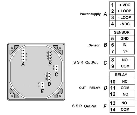
77 F9.00 Rear Terminal View Terminal F9.00.L Terminal F9.02.L Terminal F
78 F9.00 Technical Data General n Associated flow sensor: - FLS FLOWX3 Hall effect with frequency output. n FLS FLOWX3 New Electromagnetic flow sensor*. n Materials: - Case: PC - Panel gasket: Neoprene - Wall and Field gasket: EPDM - Keypad: 5 button silicone rubber. n Display: - backlight configuration (not available for F9.03) - 3 line LCD: 2 x 12 alphanumeric lines and 1 icon line - Update rate: 1 second - Contrast: User adjustable with 5 levels. n Enclosure: IP65 front. Electrical n Supply Voltage: 12 to 24 VDC ±10%, regulated. n Sensor Input (Frequency): - Sensor power: < 30 ma* - Range: F9.00.L-F9.03 à 0.5 to 500 Hz F9.02 à 0.5 to 1000 Hz - Optically isolated from current loop (only 4 wires version) - Short circuit protected. - Accuracy: ±0,5%. n Current output: ma, isolated, fully adjustable and reversible. (Not available for F9.00.L when backlight configuration is on). - Max loop impedance: VDC, VDC, VDC. n Open Collector output or Solid State Relay output: - User selectable as MIN alarm, MAX alarm, Pulse Out, Freq Out, Off, Window - Optically isolated, 50 ma MAX sink, 24 VDC maximum pull-up voltage - Max pulse/min: 300 (180 for F9.00.L) - Hysteresis: User selectable. n Relay output: - User selectable as MIN alarm, MAX alarm, Window, Pulse Out, Off - Mechanical SPDT contact - Max voltage rating: 24 VDC, 240 VAC, resistive load - Max pulse/min: 60 for F9.00, 180 for F Hysteresis: User selectable. - Expected mechanical life (min. operations): Expected electrical life (min. operations): 10 5, for F9.03 N.O.: 5 X 10 4 / N.C.: 2 X 10 5 N.O./N.C.switching capacity 8A@240 VAC, for F9.03 N.O. 250VAC / N.C. 250VAC Environmental n Operating temperature: -10 C to +70 C (14 F to 158 F). n Storage temperature: -15 C to +80 C (5 F to 176 F). n Relative humidity: 0 to 95% non condensing. Standards & Approvals n Manufactured under ISO 9001 (Quality). n Manufactured under ISO (Environmental Management). n CE. * For F3.60M & F3.63M power supply must be provided separately. 77
79 F9.00 Ordering Data F9.0X.L or F9.03 Part No. Description Wire Power Tech. Power Supply Input Output F9.00.L Flow Monitor & Transmitter 2 wire 12 to 24 VDC 1 (Freq.) 1 (4-20mA) 1 (solid state relays) F9.02.L Flow Monitor & Transmitter 3/4 wire 12 to 24 VDC 1 (Freq.) 1 (4-20mA) 2 (open collector relays) 1 (relay) F9.03 Flow Monitor & Transmitter 3/4 wire 12 to 24 VDC 2 (Freq.) 2 (4-20mA) 1 (open collector relays) 2 (relay) F9.0X.P1.L or F9.03.P1 (Panel Mount version) Part No. Description Wire Power Tech. Power Supply Input Output F9.00.P1.L Panel Mount Flow Monitor 2 wire 12 to 24 VDC 1 (Freq.) 1 (4-20mA) & Transmitter 1 (solid state relays) F9.02.P1.L Panel Mount Flow Monitor 3/4 wire 12 to 24 VDC 1 (Freq.) 1 (4-20mA) & Transmitter 2 (solid state relays) 1 (relay) F9.03.P1 Panel Mount Flow Monitor 3/4 wire 12 to 24 VDC 2 (Freq.) 2 (4-20mA) & Transmitter 1 (open collector relays) 2 (relay) F9.0X.WX.L or F9.03.WX (Wall Mount version) Part No. Description Wire Power Tech. Power Supply Input Output F9.00.W1.L Wall Mount Flow Monitor 2 wire 12 to 24 VDC 1 (Freq.) 1 (4-20mA) & Transmitter 1 (solid state relays) F9.02.W1.L Wall Mount Flow Monitor 3/4 wire 12 to 24 VDC 1 (Freq.) 1 (4-20mA) & Transmitter 2 (solid state relays) 1 (relay) F9.03.W1 Wall Mount Flow Monitor 3/4 wire 12 to 24 VDC 2 (Freq.) 2 (4-20mA) & Transmitter 1 (open collector) 2 (relay) F9.00.W2.L Wall Mount Flow Monitor 2 wire 110 to 230 VAC 1 (Freq.) 1 (4-20mA) & Transmitter 1 (solid state relays) F9.02.W2.L Wall Mount Flow Monitor 3/4 wire 110 to 230 VAC 1 (Freq.) 1 (4-20mA) & Transmitter 2 (solid state relays) 1 (relay) F9.03.W2 Wall Mount Flow Monitor 3/4 wire 110 to 230 VAC 2 (Freq.) 2 (4-20mA) & Transmitter 1 (open collector) 2 (relay) 78
80 F9.00 Ordering Data FLOWX3 F9.00.XX.L (Compact Field Mount version) Part No. Description Wire Power Supply Input Output Sensor Sensor Sensor Power Tech. Length Body O-rings F L Field Mount Flow 2 wire 12 to 24 VDC 1 (Freq.) 1 (4-20mA) L0 CPVC EPDM Monitor & Transmitter 1 (solid state relays) F L Field Mount Flow 2 wire 12 to 24 VDC 1 (Freq.) 1 (4-20mA) L0 CPVC FPM Monitor & Transmitter 1 (solid state relays) F L Field Mount Flow 2 wire 12 to 24 VDC 1 (Freq.) 1 (4-20mA) L1 CPVC EPDM Monitor & Transmitter 1 (solid state relays) F L Field Mount Flow 2 wire 12 to 24 VDC 1 (Freq.) 1 (4-20mA) L1 CPVC FPM Monitor & Transmitter 1 (solid state relays) F L Field Mount Flow 2 wire 12 to 24 VDC 1 (Freq.) 1 (4-20mA) L0 PVDF EPDM Monitor & Transmitter 1 (solid state relays) F L Field Mount Flow 2 wire 12 to 24 VDC 1 (Freq.) 1 (4-20mA) L0 PVDF FPM Monitor & Transmitter 1 (solid state relays) F L Field Mount Flow 2 wire 12 to 24 VDC 1 (Freq.) 1 (4-20mA) L1 PVDF EPDM Monitor & Transmitter 1 (solid state relays) F L Field Mount Flow 2 wire 12 to 24 VDC 1 (Freq.) 1 (4-20mA) L1 PVDF FPM Monitor & Transmitter 1 (solid state relays) F L Field Mount Flow 2 wire 12 to 24 VDC 1 (Freq.) 1 (4-20mA) L0 316L SS EPDM Monitor & Transmitter 1 (solid state relays) F L Field Mount Flow 2 wire 12 to 24 VDC 1 (Freq.) 1 (4-20mA) L0 316L SS FPM Monitor & Transmitter 1 (solid state relays) F L Field Mount Flow 2 wire 12 to 24 VDC 1 (Freq.) 1 (4-20mA) L1 316L SS EPDM Monitor & Transmitter 1 (solid state relays) F L Field Mount Flow 2 wire 12 to 24 VDC 1 (Freq.) 1 (4-20mA) L0 316L SS FPM Monitor & Transmitter 1 (solid state relays) F L Field Mount Flow 2 wire 12 to 24 VDC 1 (Freq.) 1 (4-20mA) L0 BRASS EPDM Monitor & Transmittera 1 (solid state relays) F L Field Mount Flow 2 wire 12 to 24 VDC 1 (Freq.) 1 (4-20mA) L1 BRASS FPM Monitor & Transmitter 1 (solid state relays) F L Field Mount Flow 2 wire 12 to 24 VDC 1 (Freq.) 1 (4-20mA) L1 BRASS EPDM Monitor & Transmitter 1 (solid state relays) F L Field Mount Flow 2 wire 12 to 24 VDC 1 (Freq.) 1 (4-20mA) L1 BRASS FPM Monitor & Transmitter 1 (solid state relays) 79
81 F9.00 Ordering Data FLOWX3 F9.02.XX.L (Compact Field Mount version) Part No. Description Wire Power Supply Input Output Sensor Sensor Sensor Power Tech. Length Body O-rings F L Field Mount Flow 3/4 wire 12 to 24 VDC 1 (Freq.) 1 (4-20mA) L0 CPVC EPDM Monitor & Transmitter 2 (solid state relays) 1 (Relay) F L Field Mount Flow 3/4 wire 12 to 24 VDC 1 (Freq.) 1 (4-20mA) L0 CPVC FPM Monitor & Transmitter 2 (solid state relays) 1 (Relay) F L Field Mount Flow 3/4 wire 12 to 24 VDC 1 (Freq.) 1 (4-20mA) L1 CPVC EPDM Monitor & Transmitter 2 (solid state relays) 1 (Relay) F L Field Mount Flow 3/4 wire 12 to 24 VDC 1 (Freq.) 1 (4-20mA) L1 CPVC FPM Monitor & Transmitter 2 (solid state relays) 1 (Relay) F L Field Mount Flow 3/4 wire 12 to 24 VDC 1 (Freq.) 1 (4-20mA) L0 PVDF EPDM Monitor & Transmitter 2 (solid state relays) 1 (Relay) F L Field Mount Flow 3/4 wire 12 to 24 VDC 1 (Freq.) 1 (4-20mA) L0 PVDF FPM Monitor & Transmitter 2 (solid state relays) 1 (Relay) F L Field Mount Flow 3/4 wire 12 to 24 VDC 1 (Freq.) 1 (4-20mA) L1 PVDF EPDM Monitor & Transmitter 2 (solid state relays) 1 (Relay) F L Field Mount Flow 3/4 wire 12 to 24 VDC 1 (Freq.) 1 (4-20mA) L1 PVDF FPM Monitor & Transmitter 2 (solid state relays) 1 (Relay) F L Field Mount Flow 3/4 wire 12 to 24 VDC 1 (Freq.) 1 (4-20mA) L0 316L SS EPDM Monitor & Transmitter 2 (solid state relays) 1 (Relay) F L Field Mount Flow 3/4 wire 12 to 24 VDC 1 (Freq.) 1 (4-20mA) L0 316L SS FPM Monitor & Transmitter 2 (solid state relays) 1 (Relè) F L Field Mount Flow 3/4 wire 12 to 24 VDC 1 (Freq.) 1 (4-20mA) L1 316L SS EPDM Monitor & Transmitter 2 (solid state relays) 1 (Relay) F L Field Mount Flow 3/4 wire 12 to 24 VDC 1 (Freq.) 1 (4-20mA) L1 316L SS FPM Monitor & Transmitter 2 (solid state relays) 1 (Relay) F L Field Mount Flow 3/4 wire 12 to 24 VDC 1 (Freq.) 1 (4-20mA) L0 BRASS EPDM Monitor & Transmitter 2 (solid state relays) 1 (Relay) F L Field Mount Flow 3/4 wire 12 to 24 VDC 1 (Freq.) 1 (4-20mA) L0 BRASS FPM Monitor & Transmitter 2 (solid state relays) 1 (Relay) F L Field Mount Flow 3/4 wire 12 to 24 VDC 1 (Freq.) 1 (4-20mA) L1 BRASS EPDM Monitor & Transmitter 2 (solid state relays) 1 (Relay) F L Field Mount Flow 3/4 wire 12 to 24 VDC 1 (Freq.) 1 (4-20mA) L1 BRASS FPM Monitor & Transmitter 2 (solid state relays) 1 (Relay) 80
82 F9.00 Ordering Data Mounting Kits Part No. Name Description F9.KC1 Compact mounting Kit Plastic adapter with gasket, compact cap, locking ring and 4 fixing screws F9.KP1.2 Panel mounting Kit Mounting bracket with gasket F9.KW1 Wall mounting Kit Plastic adapter with gasket and fixing screws F9.KW2 Wall mounting Kit with Power Supply Plastic adapter with gasket, fixing screws and 110/230VAC to 24VDC power supply included Spare Parts Item Part No. Name Description 1 F9.SP2 Cover PC front cover, 3 LED 1 F9.SP3 Cover PC front cover, no LED 2 F9.SP4.1 PG 13.5 PG13.5 Cable Gland for Compact or Wall mounting Kit 2 F9.SP4.2 PG 11 PG11 Cable Gland for Compact or Wall mounting Kit
 into a display indication and a 4-20mA signal for long distance transmission and it also perform a fully programmable Open Collector digital output.")
83 F9.00.BD FLOWX3 F9.00.BD Bi-directional Flow Monitor & Transmitter The FLS FLOWX3 F9.00.BD Flow Monitor and Transmitter is designed to convert the signal from the bi-directional flow sensors (F111.HT.BD & F3.11.H.BD) into a display indication and a 4-20mA signal for long distance transmission and it also perform a fully programmable Open Collector digital output. Only one packaging for panel or wall installation makes the device very flexible. Self explaining calibration menus allow a customized setup of all measuring parameters and the state of the art electronic design ensures long-term reliable and stable signals. Main Features n Wall or Panel installation n Adjustable analog output. n Flow rate and direction display. n 2 resettable totalizers (6 digit). n 2 permanent totalizers (10 digit). n Digital Open Collector output. n Output simulation for system testing. n IP65 monolithic packaging. n Auto-calibration. Applications Technical Features n Flow control and monitoring. n Water distribution. n Leak detection. n Water treatment. n Filtration systems. n Groundwater remediation. n Irrigation. Removable cover 12-digit alphanumeric line 3 line LCD Display 12-digit alphanumeric line Output status icon line 5-button silicone rubber keypad ¼ DIN, IP65 monolithic enclosure 82

 for each flow direction.")
84 F9.00.BD Technical Features Flow Part. No. Wire Power Associated 4-20mA Open Collector Relay Monitor Tech. Sensor Output Output Output F9.00.BD 2 wire Bi-directional MIN, ---- Hall Effect Positive Flow, MAX, Pulse, F3.11.H.BD Negative Flow, Off F111.HT.BD Bi-directional Flow Engineering Data n The flow transmitter is designed with only one packaging for panel or wall installation. n The flow transmitter has ¼ DIN panel mount standard dimensions: 96 x 96 mm (3.6 x 3.8 inch). n The instrument provides bi-directional flow rate indication and dual totalization (resettable and permanent) for each flow direction. n The 4-20mA output can be proportional to positive flow, negative flow or bi-directional flow with elevated zero ( ma). n The instrument provides auto-calibration and simulation options. Dimensions Panel Mount Wall Mount 83
, while the wall mounting version is fixed to the wall by the mounting kit (F9.KWX). The mounting kits can be ordered directly connected to the monitor or separately and then simply installed on it.")
85 F9.00.BD Installation The flow monitor & transmitter is available just in one packaging for panel or wall installation. The panel version is installed using the panel mounting kit (F9.KP1.2), while the wall mounting version is fixed to the wall by the mounting kit (F9.KWX). The mounting kits can be ordered directly connected to the monitor or separately and then simply installed on it. Please refer to Ordering Data section for a complete listing of part numbers. Panel Mount The panel mounting version consists of the monitor and the mounting bracket kit F9.KP1.2 with gasket for IP65 watertight panel installation. The monitor perfectly fits into a standard ¼ DIN panel cutout. The instrument and the kit can be ordered separately (code F9.0X for the monitor and code F9.KP1.2 for the mounting bracket) or together using the code F9.0X.P1. F9.00.BD Flow Monitor & Transmitter F9.KP1.2 Panel Mounting Kit F9.00.BD.P1 Panel Mount Monitor & Transmitter Input from FLS FLOWX3 Flow Sensor (sold separately) F3.11.H.BD F111.HT.BD 84

86 F9.00.BD Installation Wall Mount The wall mounting version consists of the monitor and the wall mounting kit. The F9.KW1 kit includes the plastic adapter, the gasket for IP65 watertight wall installation and the fixing screws. The F9.KW2 includes also a 110/230 VAC to 24 VDC power supply directly mounted into the plastic adapter to provide a low voltage regulated output to the flow monitor. The instrument and the kit can be ordered separately (code F9.0X for the monitor and code F9.KWX for the kit) or together using the code F9.0X.WX. F9.00.BD Flow Monitor & Transmitter F9.KWX Wall Mounting Kit F9.00.BD.WX Wall Mount Monitor & Transmitter Input from FLS FLOWX3 Flow Sensor (sold separately) F3.11.H.BD F111.HT.BD 85

87 F9.00.BD Rear Terminal View Terminal F9.00.BD Technical Data General n Associated flow sensor: - FLS F3.11.H.BD - FLS F111.HT.BD. n Materials: - Case: PC - Panel gasket: Neoprene - Wall gasket: EPDM - Keypad: 5 button silicone rubber. n Display: - 3 line LCD: 2 x 12 alphanumeric lines and 1 icon line - Update rate: 1 second - Contrast: user adjustable with 5 levels. n Enclosure: IP65 front. Electrical n Supply Voltage: 12 to 24 VDC±10%, regulated. n Sensor Input (Frequency): - Sensor power: 4 < 20 ma - Range: Hz - Optically isolated from current loop - Short circuit protected. - Accuracy: ±0,5 Hz. n Output current: ma, isolated, fully adjustable and reversible - Max. loop impedance: 12 VDC, 18 VDC, 24 VDC. n Open Collector output: - User selectable as MIN alarm, MAX alarm, Pulse Out, Off - Optically isolated, 50 ma MAX sink, 24 VDC maximum pull-up voltage - Max pulse/min.: Hysteresis: user selectable. Environmental n Operating temperature: -10 C to +70 C (14 F to 158 F). n Storage temperature: -15 C to +80 C (5 F to 176 F). n Relative Umidity: 0 to 95% non condensing. Standard & Approvals n Manufactured under ISO 9001 (Quality). n Manufactured under ISO (Environmental Management). n CE. Ordering Data FLOWX3 F9.00.BD Part No. Description Wire Power Tech. Power Supply Input Output F9.00.BD Bi-directional 2 wire 12 to 24 VDC 1 (Freq.) 1 (4-20mA) Flow Monitor and Transmitter 1 (Open Collector) FLOWX3 F9.00.BD.P1 (Panel Mount Version) Part No. Description Wire Power Tech. Power Supply Input Output F9.00.BD.P1 Panel Mount Bi-directional 2 wire 12 to 24 VDC 1 (Freq.) 1 (4-20mA) Flow Monitor and Transmitter 1 (Open Collector) FLOWX3 F9.00.BD.WX (Wall Mount Version) Part No. Description Wire Power Tech. Power Supply Input Output F9.00.BD.W1 Wall Mount Bi-directional 2 wire 12 to 24 VDC 1 (Freq.) 1 (4-20mA) Flow Monitor and Transmitter 1 (Open Collector) F9.00.BD.W2 Wall Mount Bi-directional 2 wire 110 to 230 VAC 1 (Freq.) 1 (4-20mA) Flow Monitor and Transmitter 1 (Open Collector) 86

88 F9.00.BD Ordering Data Mounting Kits Part No. Name Description F9.KP1.2 Panel mounting Kit Mounting bracket with gasket F9.KW1 Wall mounting Kit Plastic adapter with gasket and fixing screws F9.KW2 Wall mounting Kit Plastic adapter with gasket, fixing screws with Power Supply and 110/230VAC to 24VDC power supply included F9.KP1.2 Spare Parts Item Part No. Name Description 1 F9.SP1 Cover PC front cover, 1 LED 2 F9.SP4.1 PG 13.5 PG13.5 Cable Gland for Wall mounting Kit 2 F9.SP4.2 PG 11 PG11 Cable Gland for Wall mounting Kit


89 FLOWX3 F9.20 Battery Powered Flow Monitor F9.20 FLS FLOWX3 F9.20 Battery Powered Flow Monitor is equipped with two long life lithium batteries and integrates the power supply for the sensor. It is designed to show on the LCD display flow rate and totalized flow volume with no external power supply required. One of the two totalizers is resettable while the other is non-resettable and it is used to permanently record volume consumption. Self explaining calibration menus allow a customized setup of all measuring parameters and the state of the art electronic design ensures long-term reliable and stable indications. The high flexibility is maximized with only one packaging for compact pipe mount, panel or wall installation. Main Features n Battery Operated. n Long-lasting 3.6 Volt lithium batteries included. n 3 line alphanumeric LCD. n IP65 monolithic packaging. n 5 button keypad. n No information lost during battery replacement. n One packaging for compact/pipe, panel or wall installation. n Self explaining calibration menus. n Two totalizers: 10 digit permanent and 6 digit resettable. n 5 digit flow rate indication. Applications Technical Features n Water treatment and regeneration systems. n Mobile wastewater treatment and recovery. n Water distribution. n Leak detection. n Irrigation. n Groundwater remediation. n Filtration systems. n Liquid delivery systems. n Swimming pools & Spas. Removable Cover 3 line LCD display Low Battery Indication 12 digit alphanumeric line 5 button silicone rubber keypad 12 digit alphanumeric line ¼ DIN, IP65 monolithic enclosure 88
. n The instrument meets IP65 standards. n The instrument provides flow rate indication and dual totalization with fully scaleable engineering units.")

90 F9.20 Engineering Data n The flow monitor is designed with only one packaging for compact/pipe, panel or wall installation. n The flow monitor has ¼ DIN panel mount standard dimensions: 96 x 96 mm (3.8 x 3.8 inch). n The instrument meets IP65 standards. n The instrument provides flow rate indication and dual totalization with fully scaleable engineering units. n The flow monitor is equipped with a 3 line LCD: 2 x 12 alphanumeric lines and 1 icon line. n The LCD display provides a 5 digit flow rate indication, a 6 digit resettable totalizer indication and a 10 digit permanent totalizer indication. n The flow monitor is equipped with a silicone rubber 5 button keypad. n The instrument is compatible with all FLS FLOWX3 Coil and Reed sensors. n The flow monitor is equipped with internal 3.6 Volt, 2.8 Amp/hour, lithium batteries with a nominal life expectation of 5 years. n The instrument provides a low battery indication and a system to retain all calibration settings during battery replacement. Connections to FLOWX3 Sensors Flow X3 Monitors FLOWX3 Sensors F3.00.H F3.00.C F3.01.H F3.01.C F3.10.H F3.15.H* F3.30.H* ULF.H ULF.R ULF3.15* ULF3.30* F3.80 F111.H F111.C F3.60M F3.63M F9.20 * with Output Kit mounted. Dimensions Compact Mount Panel Mount Wall Mount 89
91 F9.20 Installation The flow monitor is available just in one packaging for compact field version, panel or wall installation. The compact field version is mounted on top of the sensor using the compact mounting kit (F9.KC1), the panel version is installed using the panel mounting kit (F9.KP1.2), while the wall mounting version is fixed to the wall by the mounting kit (F9.KW1). The mounting kits can be ordered directly connected to the monitor or separately and then simply installed on it. Please refer to Ordering Data section for a complete listing of part numbers. Panel Mount Input from The panel mounting version consists of the monitor and the mounting bracket kit F9.KP1.2 with gasket for IP65 watertight panel installation. The monitor perfectly fits into a standard ¼ DIN panel cutout. The instrument and the kit can be ordered separately (code F9.20 for the monitor and code F9.KP1.2 for the mounting bracket) or together using the code F9.20.P1. F9.20 Battery Powered Flow Monitor F9.KP1.2 Panel Mounting Kit F9.20.P1 Panel Mount Battery Powered Monitor Input from FLS FlowX3 Flow Sensor (sold separately) F3.00.C.XX ULF01.R.X ULF03.R.X F111.C 90
92 F9.20 Installation Wall Mount Input from The wall mounting version consists of the monitor and the wall mounting kit. The F9.KW1 kit includes the plastic adapter, the gasket for IP65 watertight wall installation and the fixing screws. The instrument and the kit can be ordered separately (code F9.20 for the monitor and code F9.KW1 for the kit) or together using the code F9.20.W1. F9.20 Battery Powered Flow Monitor F9.KW1 Wall Mounting Kit F9.20.W1 Wall Mount Battery Powered Monitor Input from FLS FlowX3 Flow Sensor (sold separately) F3.00.C.XX ULF01.R.X ULF03.R.X F111.C 91

93 F9.20 Installation Compact Mount The compact mounting kit F9.KC1 includes the compact plastic adapter with gasket for IP65 watertight installation, the compact cap, the locking ring and four fixing screws for mounting the monitor directly onto the sensor. The instrument and the kit can be ordered separately (code F9.20 for the monitor and code F9.KC1 for the kit) or together using the code F9.20.XX. F9.20 Battery Powered Flow Monitor F9.KC1 Compact Mounting Kit including: fixing screws, locking ring, compact adapter, compact cap F3.01.C.XX Flow Sensor F9.20.XX Compact Battery Powered Flow Monitor 92

94 F9.20 Rear Terminal View Terminal F9.20 Technical Data General n Associated flow sensor: - FLS FlowX3 Coil effect with frequency output - FLS FlowX3 Reed effect. n Materials: - Case: PC - Panel gasket: Neoprene - Wall and Field gasket: EPDM - Keypad: 5 button silicone rubber. n Display: - 3 line LCD: 2 x 12 alphanumeric lines and 1 icon line - Update rate: 1 second. n Enclosure: IP65 front. Environmental n Operating temperature: -5 C to +60 C (23 F to 140 F). n Storage temperature: -1 C to +80 C (14 F to 176 F). n Relative humidity: 0 to 95% non condensing. Standards & Approvals n Manufactured under ISO 9001 (Quality). n Manufactured under ISO (Environmental Management). n CE. Electrical n Supply Voltage: 2 x 3.6 Volt Lithium thionylchloride battery, 2.8 AHr. n Battery life: nominal 5 years. n Sensor Input (Frequency): - Sensor power: 3.6 Volt - Range: 1 to 500 Hz. - Accuracy: ±0,5 Hz. 93
95 F9.20 Ordering Data FLOWX3 F9.20.XX Part No Description F9.20 Battery Powered Flow Monitor F9.20.W1 Panel Mount Battery Powered Flow Monitor F9.20.P1 Wall Mount Battery Powered Flow Monitor FlowX3 F9.20.XX (Compact Field Mount version) Part No. Description Sensor Length Sensor Body Sensor O-rings F Field Mount Battery L0 CPVC EPDM Powered Flow Monitor F Field Mount Battery L0 CPVC FPM Powered Flow Monitor F Field Mount Battery L1 CPVC EPDM Powered Flow Monitor F Field Mount Battery L1 CPVC FPM Powered Flow Monitor F Field Mount Battery L0 PVDF EPDM Powered Flow Monitor F Field Mount Battery L0 PVDF FPM Powered Flow Monitor F Field Mount Battery L1 PVDF EPDM Powered Flow Monitor F Field Mount Battery L1 PVDF FPM Powered Flow Monitor F Field Mount Battery L0 316L SS EPDM Powered Flow Monitor F Field Mount Battery L0 316L SS FPM Powered Flow Monitor F Field Mount Battery L1 316L SS EPDM Powered Flow Monitor F Field Mount Battery L1 316L SS FPM Powered Flow Monitor F Field Mount Battery L0 BRASS EPDM Powered Flow Monitor F Field Mount Battery L0 BRASS FPM Powered Flow Monitor F Field Mount Battery L1 BRASS EPDM Powered Flow Monitor F Field Mount Battery L1 BRASS FPM Powered Flow Monitor 94


96 F9.20 Ordering Data Mounting Kits Part No. Name Description F9.KC1 Compact mounting Kit Plastic adapter with gasket, compact cap, locking ring and 4 fixing screws F9.KP1.2 Panel mounting Kit Mounting bracket with gasket F9.KW1 Wall mounting Kit Plastic adapter with gasket and fixing screws F9.KP1.2 Spare Parts Item Part No. Name Description 1 F9.SP3 Cover PC front cover, no LED 2 F9.SP4.1 PG 13,5 PG13,5 Cable Gland for Compact or Wall mounting Kit F9.SP4.2 PG 11 PG11 Cable Gland for Compact or Wall mounting Kit 3 F9.SP6 Replacement battery 3.6 Volt Lithium thionyl chloride battery
97 F9.20.BD FLOWX3 F9.20.BD Bi-directional Battery Powered Flow Monitor The FLS FLOWX3 F9.20.BD Bi-directional Battery Powered Flow Monitor is equipped with two long life lithium batteries and integrates the power supply for the sensor. It is designed to show on the LCD display flow rate and totalized flow volume with no external power supply required. The instant flow rate can be positive or negative, according to flow direction. Two totalizers (resettable and permanent) are available for positive flow and two totalizers (resettable and permanent) are available for negative flow. Self explaining calibration menus allow customized setup of all measuring parameters and the state of the art electronic design ensures long-term reliable and stable indications. Main Features n Wall installation. n Battery operated. n No information lost during battery replacement. n Flow rate and direction display. n 2 resettable totalizers (6 digit). n 2 permanent totalizers (10 digit). n Self explaining calibration menu. n IP65 monolithic packaging. Applications n Flow monitoring. n Water distribution. n Leak detection. n Irrigation. n Filtration systems. n Groundwater remediation. Technical Features Removable cover 3 line LCD Display 12-digit alphanumeric line 12-digit alphanumeric line Low battery indication 5-button silicone rubber keypad ¼ DIN, IP65 monolithic enclosure Engineering Data n The flow monitor is designed for wall installation. n The instrument is compatible with F111.HT.BD & F3.11.H.BD flow sensors. n The instrument provides bi-directional flow rate indication and dual totalization (resettable and permanent) for each flow direction. n The monitor provides a low battery indication and a system to retain all calibration settings during battery replacement. n The instrument meets IP65 standards. 96

 or together using the code F9.0X.P1. F9.20.")
98 F9.20.BD Dimensions Wall Mount Installation The flow monitor & transmitter is available just in one packaging for wall installation. Wall Mount The wall mounting version consists of the monitor and the wall mounting kit. The F9.KW3 kit includes the plastic adapter, the gasket for IP65 watertight wall installation, the fixing screws and the batteries. The instrument and the kit can be ordered separately (code F9.0X for the monitor and code F9.KP1.2 for the mounting bracket) or together using the code F9.0X.P1. F9.20.BD Flow Monitor & Transmitter F9.KW3 Wall Mounting Kit F9.20.BD.W3 Wall Mount Monitor & Transmitter Input from FLS FLOWX3 Flow Sensor (sold separately) F3.11.H.BD F111.HT.BD 97

99 F9.20.BD Rear Terminal View Terminal F9.20.BD Technical Data General n Associated flow sensor: - FLS F 3.11.H.BD - FLS F111.HT.BD. n Materials: - Case: PC - Panel gasket: Neoprene - Wall gasket: EPDM - Keypad: 5 button silicone rubber. n Display: - 3 line LCD: 2 x 12 alphanumeric lines and 1 icon line - Update rate: 1 second. n Enclosure: IP65 front. Electrical n Supply Voltage: 2 x 3.6 Volt Lithium thionyl chloride battery, 16.5 Ahr. n Battery life: nominal 2 years. n Sensor Input (Frequency): - Sensor power: 4 Volt - Range: Hz. - Accuracy: ±0,5 Hz. Environmental n Operating temperature: -5 C to +60 C (23 F to 140 F). n Storage temperature: -10 C to +80 C (14 F to 176 F). n Relative Umidity: 0 to 95% non condensing. Standard & Approvals n Manufactured under ISO 9001 (Quality). n Manufactured under ISO (Environmental Management). n CE. Ordering Data FLOWX3 F9.20.BD Part No.Description F9.20.BD Bi-directional Battery Powered Flow Monitor FLOWX3 F9.20.BD.W3 (Wall Mount Version) Part No Description F9.20.BD.W3 Wall Mount Bi-directional Battery Powered Flow Monitor 98

100 F9.20.BD Ordering Data Mounting Kits Part No.Name Description F9.KW3 Wall mounting Kit Plastic adapter with gasket, fixing screws with batteries included and batteries included F9.KW3 Spare Parts Item Part No.Name Description 1 F9.SP3 Cover PC front cover, no LED 2 F9.SP4.1 PG 13.5 PG13.5 Cable Gland for Wall mounting Kit 2 F9.SP4.2 PG 11 PG11 Cable Gland for Wall mounting Kit 3 F9.SP5 Battery Kit replacement 2x3.6 Volt, two Lithium thionyl chloride battery Kit
101 FLOWX3 F9.50.L Batch Controller F9.50.L The FLS FlowX3 F9.50.L Batch Controller family is designed for accurate and reliable batching or blending of a variety of liquids. The instrument combines complex control capability with easy calibration and operation. Simple and Advanced mode are available to customize the unit to the specific batch requirements providing simple and quick changes of batch volumes and settings. The F9.50.L, with two relays, a solid state relay and an analog output, ensure accurate batch operation reducing the possibility of water hammer into the system. While with the F9.51.L is possible to store up to 10 different batch parameters batching different volumes and different liquids in the same pipeline always with the same accuracy. The high flexibility is maximized with only one packaging for compact pipe mount, panel or wall installation. Self explaining calibration menus and 5-button keypad allow a user friendly setup of all the batch parameters while the high visible backlight LCD display can show batch in progress, instant and totalized flow. Main Features n Easy Batch Volume setting. n Simple and Advanced operating modes. n External Start, Stop and Resume. n Self explaining calibration menus. n Auto-calibration. n Two Stage Shutdown Control (F9.50.L). n Overrun Alarm. n Missing Signal Alarm. n End-of-Batch Pulse Output. n Output simulation for system testing. n Count-up or Count-down batch indication (F9.50.L). n Permanent and Resettable totalizer. n 3 line alphanumeric backlight LCD. n IP65 monolithic packaging. n 5 button keypad. n One packaging for compact/pipe, panel or wall installation. n Automatic or Manual Overrun Compensation (F9.50.L). n Advanced Valve Control (F9.50.L). n Count-up or Count-down batch indication (F9.50.L). n Store up to ten different batch parameters (F9.51.L). n Count-up batch indication (F9.51.L). Applications n Batch Processes. n Chemicals Addition. n Filling Processes. n Blending Applications. 100

102 F9.50.L Technical Features Removable Cover 12 digit alphanumeric line 12 digit alphanumeric line Output status icon line OUT 1 LED OPT LED 3 line backlight LCD display OUT 2 LED 5 button silicone rubber keypad ¼ DIN, IP65 monolithic enclosure Batch Part No. Associated Storable 4-20 ma Solid state Relay Controller Flow Sensor batches Output relay LED Output F9.50.L START Batch, 2 Batch Hall Effect END Batch, Off & Option F9.51.L Batch (Effect Hall) & Option Engineering Data n The batch controller is designed with only one packaging for compact/pipe, panel or wall installation. n The batch controller has ¼ DIN panel mount standard dimensions: 96 x 96 mm (3.8 x 3.8 inch). n The instrument meets IP65 standards. n The instrument provides flow rate indication, one permanent and one resettable totalizer with fully scaleable engineering units. n The batch controller provides two SPDT relays. One relay for batch-in-progress indication, the other configurable for end-ofbatch pulse, overrun alarm or missing signal alarm in F9.50.L and F9.51.L, and two-stage shutdown only in F9.50.L version. n The instrument F9.50.L provides a 4..20mA analog output configurable for valve control, or batch completion. n The batch controller F9.50.L also provides an SSR output configurable as START Batch or END Batch. n The instrument provides also additional functions as: External Start, Stop and Resume. n The batch controller is compatible with all FLS FlowX3 Hall Effect Flow Sensor. n The batch controller is equipped with a 3 line backlight LCD: 2 x 12 alphanumeric lines & 1 icon line. n The batch controller is equipped with a Silicone rubber 5 button keypad. n The instrument provides auto-calibration and simulation options. Connections to FLOWX3 Sensors Batch Controllers FLOWX3 FLOWX3 Sensor F3.00.H F3.00.C F3.01.H F3.01.C F3.10.H F3.15.H* F3.30.H* ULF.H ULF.R ULF3.15* ULF3.30* F3.80 F111.H F111.C F3.60M F3.63M F9.50.L F9.51.L * with Output Kit mounted. 101

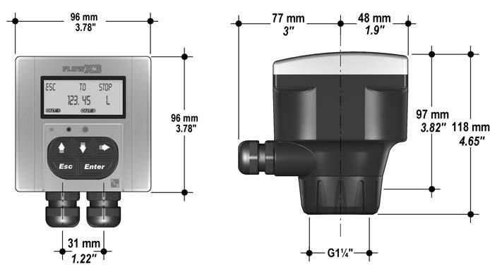
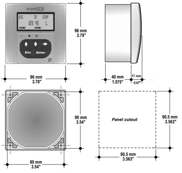
103 F9.50.L Dimensions Compact Mount Panel Mount Wall Mount 102
104 F9.50.L Installation The batch controller is available just in one packaging for compact field version, panel or wall installation. The compact field version is mounted on top of the sensor using the compact mounting kit (F9.KC1), the panel version is installed using the panel mounting kit (F9.KP1.2), while the wall mounting version is fixed to the wall by the mounting kit (F9.KWX). The mounting kits can be ordered directly connected to the controller or separately and then simply installed on it. Please refer to Ordering Data section for a complete listing of part numbers. Panel Mount Input from The panel mounting version consists of the batch controller and the mounting bracket kit F9.KP1 with gasket for IP65 watertight panel installation. The controller perfectly fits into a standard ¼ DIN panel cutout. The instrument and the kit can be ordered separately (code F9. 5X.L for the monitor and code F9.KP1 for the mounting bracket) or together using code F9.5X.P1.L. F9.5X.L Batch Controller F9.KP1.2 Panel Mounting Kit F9.5X.P1.L Panel Mount Batch Controller Input from FLS FlowX3 Flow Sensor (sold separately) F3.00.H.XX - F3.10.H.XX - F3.15.H.XX - ULF01.H.X - ULF3.15.XX.X- ULF03.H.X - F111.H - F New F3.60M & F3.63M 103

105 F9.50.L Installation Wall Mount Input from The wall mounting version consists of the batch controller and the wall mounting kit. The F9.KW1 kit includes the plastic adapter, the gasket for IP65 watertight wall installation and the fixing screws. The F9.KW2 includes also a 110/230 VAC to 24 VDC power supply directly mounted into the plastic adapter to provide a low voltage regulated output to the controller. The instrument and the kit can be ordered separately (code F9. 5X.L for the controller and code F9.KWX for the kit) or together using code F9.5X.WX.L. F9.5X.L Batch Controller F9.KWX Wall Mounting Kit F9.5X.WX.L Wall Mount Batch Controller Input da FLS FlowX3 Flow Sensor (sold separately) F3.00.H.XX - F3.15.H.XX - F3.30.H.XX ULF01.H.X - ULF3.15.XX.X - ULF03.H.X - F111.H - F New F3.60M & F3.63M 104
106 F9.50.L Installation Compact Mount The compact mounting kit F9.KC1 includes the compact plastic adapter with gasket for IP65 watertight installation, the compact cap, the locking ring and four fixing screws for mounting the batch controller directly onto the sensor. The instrument and the kit can be ordered separately (code F9. 5X.L for the controller and code F9.KC1 for the kit) or together using code F9. 5X.XX.L. F9.5X.L Batch Controller F9.KC1 Compact Mounting Kit including: fixing screws, locking ring compact adapter, compact cap F3.01.H.XX Flow Sensor F9.5X.XX.L Compact Batch Controller 105

107 F9.50.L Rear Terminal View 106
108 F9.50.L Technical Data General n Associated flow sensor: - FLS FLOWX3 Hall effect with frequency output - FLS FLOWX3 New Electromagnetic flow sensor*. n Materials: - Case: PC - Panel gasket: Neoprene - Wall & Field gasket: EPDM - Keypad: 5-button silicone rubber. n Display: - backlight configuration - 3 line LCD: 2 x 12 alphanumeric lines + 1 icon line - Update rate: 1 second - Contrast: User adjustable with 5 levels. n Enclosure: IP65 front Electrical n Supply Voltage: 12 to 24 VDC ±10% regulated. n Sensor Input (Frequency): - Sensor power: < 30 ma - Range: 0.5 to 1000 Hz - Optically isolated from current loop - Short circuit protected - Accuracy:± 0,50 Hz. n Relay output: - Mechanical SPDT contact - Expected mechanical life (min. operations): Expected electrical life (min. operations): q N.O./N.C. switching capacity VAC n of operations 10 x OUT1 Batch: Batch in progress indication - OUT2 Option: End of batch, overrun alarm, missing signal alarm. n Additional Functions: - External Start, Stop and Resume. F9.50.L specific n Relay output: - OUT2 Option: Two-stage shutdown n Current output: ma, isolated, fully adjustable and reversible - Max loop impedance: VDC, VDC, VDC - Configurations: Valve control, batch completion n Solid state relays: - User selectable as START Batch, END Batch, OFF - Optically isolated, 50 ma MAX sink, 24 VDC MAX pull-up voltage - Max puls e/min: 300. n Additional Functions: - End of batch pulse. Environmental n Operating temperature: -10 C to +70 C (14 F to 158 F) n Storage temperature: -15 C to +80 C (5 F to 176 F) n Relative humidity: 0 to 95% non condensing. Standards and Approvals n Manufactured under ISO 9001 (Quality). n Manufactured under ISO (Environmental Management). n CE. * For F3.60M & F3.63M power supply must be supplied separately. 107
109 F9.50.L Ordering Data FlowX3 F9.5X.L Part No. Description Power Supply Input F9.50.L Batch Controller 12 to 24 VDC 1 (Freq.) F9.51.L Batch Controller 12 to 24 VDC 1 (Freq.) FlowX3 F9.5X.P1.L (Panel Mount version) Part No. Description Power Supply Input F9.50.P1.L Panel Mount 12 to 24 VDC 1 (Freq.) Batch Controller F9.51.P1.L Panel Mount 12 to 24 VDC 1 (Freq.) Batch Controller FlowX3 F9.5X.WX.L (Wall Mount version) Part No. Description Power Supply Input F9.50.W1.L Wall Mount 12 to 24 VDC 1 (Freq.) Batch Controller F9.51.W1.L Wall Mount 12 to 24 VDC 1 (Freq.) Batch Controller F9.50.W2.L Wall Mount 110 to 230 VAC 1 (Freq.) Batch Controller F9.51.W2.L Wall Mount 110 to 230 VAC 1 (Freq.) Batch Controller 108
110 F9.50.L Ordering Data FlowX3 F9.5X.XX.L (Compact Field Mount version) Part No. Description Power Supply Sensor Length Sensor Body Sensor O-rings F L Field Mount Batch Controller 12 to 24 VDC L0 CPVC EPDM F L Field Mount Batch Controller 12 to 24 VDC L0 CPVC FPM F L Field Mount Batch Controller 12 to 24 VDC L1 CPVC EPDM F L Field Mount Batch Controller 12 to 24 VDC L1 CPVC FPM F L Field Mount Batch Controller 12 to 24 VDC L0 PVDF EPDM F L Field Mount Batch Controller 12 to 24 VDC L0 PVDF FPM F L Field Mount Batch Controller 12 to 24 VDC L1 PVDF EPDM F L Field Mount Batch Controller 12 to 24 VDC L1 PVDF FPM F L Field Mount Batch Controller 12 to 24 VDC L0 316L SS EPDM F L Field Mount Batch Controller 12 to 24 VDC L0 316L SS FPM F L Field Mount Batch Controller 12 to 24 VDC L1 316L SS EPDM F L Field Mount Batch Controller 12 to 24 VDC L1 316L SS FPM F L Field Mount Batch Controller 12 to 24 VDC L0 BRASS EPDM F L Field Mount Batch Controller 12 to 24 VDC L0 BRASS FPM F L Field Mount Batch Controller 12 to 24 VDC L1 BRASS EPDM F L Field Mount Batch Controller 12 to 24 VDC L1 BRASS FPM 109
111 F9.50.L Ordering Data FlowX3 F9.5X.XX.L (Compact Field Mount version) Part No. Description Power Supply Sensor Length Sensor Body Sensor O-rings F L Field Mount Batch Controller 12 to 24 VDC L0 CPVC EPDM F L Field Mount Batch Controller 12 to 24 VDC L0 CPVC FPM F L Field Mount Batch Controller 12 to 24 VDC L1 CPVC EPDM F L Field Mount Batch Controller 12 to 24 VDC L1 CPVC FPM F L Field Mount Batch Controller 12 to 24 VDC L0 PVDF EPDM F L Field Mount Batch Controller 12 to 24 VDC L0 PVDF FPM F L Field Mount Batch Controller 12 to 24 VDC L1 PVDF EPDM F L Field Mount Batch Controller 12 to 24 VDC L1 PVDF FPM F L Field Mount Batch Controller 12 to 24 VDC L0 316L SS EPDM F L Field Mount Batch Controller 12 to 24 VDC L0 316L SS FPM F L Field Mount Batch Controller 12 to 24 VDC L1 316L SS EPDM F L Field Mount Batch Controller 12 to 24 VDC L1 316L SS FPM F L Field Mount Batch Controller 12 to 24 VDC L0 BRASS EPDM F L Field Mount Batch Controller 12 to 24 VDC L0 BRASS FPM F L Field Mount Batch Controller 12 to 24 VDC L1 BRASS EPDM F L Field Mount Batch Controller 12 to 24 VDC L1 BRASS FPM 110
112 F9.50.L Ordering Data Mounting Kits Part No. Name Description F9.KC1 Compact mounting Kit Plastic adapter with gasket, compact cap, locking ring and 4 fixing screws F9.KP1.2 Panel mounting Kit Mounting bracket with gasket F9.KW1 Wall mounting Kit Plastic adapter with gasket and fixing screws F9.KW2 Wall mounting Kit with Power Supply Plastic adapter with gasket, fixing screws and 110/230VAC to 24VDC power supply included Spare Parts Item Part No. Name Description 1 F9.SP2 Cover PC front cover, 3 LED 2 F9.SP4.1 PG 13.5 PG 13.5 Cable Gland for Compact or Wall mounting Kit 2 F9.SP4.2 PG 11 PG11 Cable Gland for Compact or Wall mounting Kit

113 FLOWX3 Accessories Accessories FlowX3 24VDC Single Phase Switching Power Supply The switching power supply units provided by FLS are designed and developed for industrial uses where safety, ease of use and reliability are essential. The low working temperature at full power, combined with the use of first quality components ensure a very high lifetime. This power supply is very compact and meets IP20 standards according to IEC 529. All the functions are located on the front panel and marked with IEC symbols for a very simple use even on site. Providing an output capacity of 1.2 A, these power supplies are suitable for systems including FLS instruments or other devices requiring 24VDC operation. Main Features n Universal AC input: VAC. n Regulated 24 VDC output. n Fused input. n Output capacity: 1.2 A. n Compact dimensions. n Low noise. n DIN rail mounting. n Functions and descriptions on the Applications Suitable for use with: n Flow Sensors: F3.00.H, F3.15.H, F3.30.H, F111.H,F3.10.H. n Ultra Low Flow Sensors: ULF01.H, ULF03.H, ULF3.15, ULF3.30. n Magmeters: F3.63M, F3.60M, F9.63M, F9.60M. n Flow switches F3.05. n Oval gear Flow Sensor F3.80. n Flow Monitor & Transmitters F9.0X. n Batch Controllers F9.5X. Technical Data and Dimensions Dimensions in mm. 112
. n Max. Output Current: 2.2 A. n Continuous Output Current: 1.2 A. n Load regulation: < 0.5%.")
114 Accessories Technical Data Input n Input Voltage: VAC. n Frequency: Hz. n Input nominal load: VAC, VAC. n Inrush current: < 13 A. n Power factor: > full load. n Protection Fuse: T 2 A / 250 V. Output n Voltage: 24 VDC ± 1% (not adjustable). n Max. Output Current: 2.2 A. n Continuous Output Current: 1.2 A. n Load regulation: < 0.5%. n I max: < 50 mvpp. n Hold up full load: > VAC, > VAC. n Overload/Short circuit protection: Hiccup circuit, auto reset. n Parallel connection: possible with external protection diode. General n Efficiency: ³ 240 VAC, ³ 120 VAC. n Dissipated power: < 6 W. n Working temperature: -10 C 60 C (14 F to 140 F), A/ C ( A/ F) over 45 C (113 F). n Input/output isolation: 3 kvca / 60 s. n Input/ground isolation: > 1.5 kvca / 60 s. n Output/ground isolation: Class 2 insulation device, no PE required. n Protection class: IP20. n Connection terminal blocks: 2.5 mm 2, pluggable screw type header. n Housing material: polyamide UL94V-0. n Mounting information: vertical on DIN rail. Standards & Approvals n Safety Directives: EN 60950, IEC950, UL 1950, UL508C. n EMC Directives: EN , EN , EN n Surge immunity: EN , EN , EN Ordering Data Switching Power Supply Part No. Input Output Description F.PSCS VAC 24 VDC regulated Single Phase Power Supply 24VDC, 1 A F.IMSP1 Interface Module Flow Sensor PLC The F.IMSP1 module is designed to make a safe connection of a F3.10.XX, F111.H.XX or a F111.HT.01 to all PLC/Instruments digital inputs as well as to protect the sensor from almost any kind of electric or electromagnetic noises on the main power supply. The plastic and lightweight housing can be DIN rail mounted. Technical Data n Supply voltage: 12 to 24 VDC ± 10% regulated. n Supply current: IAlim = 11 IOut = 0. n Output signal: square wave. n Output type: Push Pull (for connection to NPN and PNP inputs). n Output current: IOut Max < 20 ma. n Mounting information: on DIN rail. Standard & Approvals n Manufactured under ISO 9001 (Quality). n Manufactured under ISO (Environmental Management). n CE. Ordering Data Modulo di interfaccia sensore - PLC Part No Input Output Description F.IMSP1 All F3.10.XX, F111.H.XX, Push-Pull Interface module flow sensor - PLC F111.HT.01 Hall Effect flow sensors 113

115 Installation Fittings for Paddlewheel and Electromagnetic Flow Sensors Installation on PVC pipes ISO Metric PVC Tee Fittings (female ends for solvent welding) Part No DN d O-Ring H Z L B E Sensor Length TFIV20B 15 20EPDM L0 TFIV25B 2025 EPDM L0 TFIV32B EPDM L0 TFIV40B 32 40EPDM L0 TFIV50B 4050EPDM L0 TFIV20D 15 20FPM L0 TFIV25D 2025 FPM L0 TFIV32D FPM L0 TFIV40D 32 40FPM L0 TFIV50D 4050FPM L0 ISO Metric Clamp Saddles Part No DN d O-Ring Body Insert E hh Drilling Sensor hole Length SCIC063BVC 5063 EPDM CPVC CPVC L0 SCIC075BVC EPDM CPVC CPVC L0 SCIC090BVC 8090EPDM CPVC CPVC L0 SCIC110BVC EPDM CPVC CPVC L0 SCIC125BVC EPDM CPVC CPVC L1 SCIC140BVC EPDM CPVC CPVC L1 SCIC160BVC EPDM CPVC CPVC L1 SCIC200BVC EPDM CPVC CPVC L1 SCIC225BVC EPDM CPVC CPVC L1 SCIC063DVC 5063 FPM CPVC CPVC L0 SCIC075DVC FPM CPVC CPVC L0 SCIC090DVC 8090FPM CPVC CPVC L0 SCIC110DVC FPM CPVC CPVC L0 SCIC125DVC FPM CPVC CPVC L1 SCIC140DVC FPM CPVC CPVC L1 SCIC160DVC FPM CPVC CPVC L1 SCIC200DVC FPM CPVC CPVC L1 SCIC225DVC FPM CPVC CPVC L1 SMIC250IVC* NBR PP CPVC L0 SMIC280IVC* NBR PP CPVC L1 SMIC315IVC* NBR PP CPVC L1 * For IP68 sensors or compact monitors only 114

116 Fittings Installation on PVC pipes PVC Glue-on Fittings Part No DN d L D1 D2 Drilling Sensor hole Length WAIV L0 WAIV L0 WAIV L0 WAIV L0 WAIV L0 WAIV L0 WAIV L0 WAIV L0 WAIV L0 WAIV L1 WAIV L1 WAIV L1 BSP version BS version BSP Female Threaded PVC Tee Fittings (parallel threaded female ends) Part No DN R O-Ring H Z L B E Sensor Length TFFV20B 15 1/2" EPDM L0 TFFV25B 203/4" EPDM L0 TFFV32B 25 1" EPDM L0 TFFV40B /4" EPDM L0 TFFV50B 401 1/2" EPDM L0 TFFV20D 15 1/2" FPM L0 TFFV25D 203/4" FPM L0 TFFV32D 25 1" FPM L0 TFFV40D /4" FPM L0 TFFV50D 401 1/2" FPM L0 BS Solvent Welding PVC Tee Fittings (female ends for solvent welding) Part No DN d O-Ring H Z L B E Sensor Length TFLV20B 15 1/2" EPDM L0 TFLV25B 203/4" EPDM L0 TFLV32B 25 1" EPDM L0. TFLV40B /4" EPDM L0 TFLV50B 401 1/2" EPDM L0 TFLV20D 15 1/2" FPM L0 TFLV25D 203/4" FPM L0 TFLV32D 25 1" FPM L0 TFLV40D /4" FPM L0 TFLV50D 401 1/2" FPM L0 115
117 Installation Installation on PVC pipes BS Clamp Saddles Part No DN d O-Ring Body Insert E hh Drilling Sensor hole Length SCLC2.0BVM 502" EPDM CPVC CPVC L0 SCLC3.0BVM 803" EPDM CPVC CPVC L0 SCLC4.0BVM 100 4" EPDM CPVC CPVC L0 SCLC6.0BVM 1506" EPDM CPVC CPVC L1 SCLC8.0BVM 200 8" EPDM CPVC CPVC L1 SCLC2.0DVM 502" FPM CPVC CPVC L0 SCLC3.0DVM 803" FPM CPVC CPVC L0 SCLC4.0DVM 100 4" FPM CPVC CPVC L0 SCLC6.0DVM 1506" FPM CPVC CPVC L1 SCLC8.0DVM 200 8" FPM CPVC CPVC L1 ASTM version NPT version ASTM SCH. 80 PVC Tee Fittings (female ends for solvent welding) Part No Size d O-Ring H Z L B E Sensor Length TFAV20B 0.50" 0.85" EPDM 4.92" 3.15" 0.89" 2.87" 2.09" L0 TFAV25B 0.75" 1.06" EPDM 5.51" 3.50" 1.00" 3.15" 2.44" L0 TFAV32B 1.00" 1.33" EPDM 6.04" 3.78" 1.13" 3.19" 2.80" L0 TFAV40B 1.25" 1.67" EPDM 7.34" 4.80" 1.26" 3.31" 3.31" L0 TFAV50B 1.50" 1.91" EPDM 8.15" 5.39" 1.38" 3.25" 3.86" L0 TFAV20D 0.50" 0.85" FPM 4.92" 3.15" 0.89" 2.87" 2.09" L0 TFAV25D 0.75" 1.06" FPM 5.51" 3.50" 1.00" 3.15" 2.44" L0 TFAV32D 1.00" 1.33" FPM 6.04" 3.78" 1.13" 3.19" 2.80" L0 TFAV40D 1.25" 1.67" FPM 7.34" 4.80" 1.26" 3.31" 3.31" L0 TFAV50D 1.50" 1.91" FPM 8.15" 5.39" 1.38" 3.25" 3.86" L0 NPT Female Threaded PVC Tee Fittings (NPT threaded female ends) Part No Size R O-Ring H Z L B E Sensor Length TFNV20B 0.50" 1/2" EPDM 4.67" 3.26" 0.70" 2.87" 2.09" L0 TFNV25B 0.75" 3/4" EPDM 5.02" 3.60" 0.71" 3.15" 2.44" L0 TFNV32B 1.00" 1" EPDM 5.75" 3.97" 0.89" 3.19" 2.80" L0 TFNV40B 1.25" 1 1/4" EPDM 6.97" 5.12" 0.93" 3.31" 3.31" L0 TFNV50B 1.50" 1 1/2" EPDM 7.52" 5.28" 1.12" 3.25" 3.86" L0 TFNV20D 0.50" 1/2" FPM 4.67" 3.26" 0.70" 2.87" 2.09" L0 TFNV25D 0.75" 3/4" FPM 5.02" 3.60" 0.71" 3.15" 2.44" L0 TFNV32D 1.00" 1" FPM 5.75" 3.97" 0.89" 3.19" 2.80" L0 TFNV40D 1.25" 1 1/4" FPM 6.97" 5.12" 0.93" 3.31" 3.31" L0 TFNV50D 1.50" 1 1/2" FPM 7.52" 5.28" 1.12" 3.25" 3.86" L0 116
118 Fittings Installation on PVC pipes ASTM SCH. 80 Clamp Saddles Part No Size d O-Ring Body Insert E hh Drilling Sensor hole Length SCAC2.0BVM 2.00" 2.375" EPDM CPVC CPVC 4.57" 3.3" 4.13" 1.38" L0 SCAC2.5BVM 2.50" 2.875" EPDM CPVC CPVC 5.28" 3.4" 4.13" 1.38" L0 SCAC3.0BVM 3.00" 3.500" EPDM CPVC CPVC 5.98" 3.6" 4.13" 1.57" L0 SCAC4.0BVM 4.00" 4.500" EPDM CPVC CPVC 6.93" 4.0" 4.13" 1.57" L0 SCAC5.0BVM 5.00" 5.520" EPDM CPVC CPVC 8.43" 5.6" 4.49" 1.57" L1 SCAC6.0BVM 6.00" 6.625" EPDM CPVC CPVC 9.37" 5.9" 4.72" 1.57" L1 SCAC8.0BVM 8.00" 8.625" EPDM CPVC CPVC 13.11" 6.6" 4.92" 1.57" L1 SCAC2.0DVM 2.00" 2.375" FPM CPVC CPVC 4.57" 3.3" 4.13" 1.38" L0 SCAC2.5DVM 2.50" 2.875" FPM CPVC CPVC 5.28" 3.4" 4.13" 1.38" L0 SCAC3.0DVM 3.00" 3.500" FPM CPVC CPVC 5.98" 3.6" 4.13" 1.57" L0 SCAC4.0DVM 4.00" 4.500" FPM CPVC CPVC 6.93" 4.0" 4.13" 1.57" L0 SCAC5.0DVM 5.00" 5.520" FPM CPVC CPVC 8.43" 5.6" 4.49" 1.57" L1 SCAC6.0DVM 6.00" 6.625" FPM CPVC CPVC 9.37" 5.9" 4.72" 1.57" L1 SCAC8.0DVM 8.00" 8.625" FPM CPVC CPVC 13.11" 6.6" 4.92" 1.57" L1 Installation on CPVC pipes ISO Metric CPVC Tee Fittings (female ends for solvent welding) Part No DN d O-Ring H Z L B E Sensor Length TFIC20B 15 20EPDM L0 TFIC25B 2025 EPDM L0 TFIC32B EPDM L0 TFIC40B 32 40EPDM L0 TFIC50B 4050EPDM L0 TFIC20D 15 20FPM L0 TFIC25D 2025 FPM L0 TFIC32D FPM L0 TFIC40D 32 40FPM L0 TFIC50D 4050FPM L0 117


119 Installation Installation on CPVC pipes ISO Clamp Saddles Part No DN d O-Ring Body Insert E hh Drilling Sensor hole Length SCIC063BVC 5063 EPDM CPVC CPVC L0 SCIC075BVC EPDM CPVC CPVC L0 SCIC090BVC 8090EPDM CPVC CPVC L0 SCIC110BVC EPDM CPVC CPVC L0 SCIC125BVC EPDM CPVC CPVC L1 SCIC140BVC EPDM CPVC CPVC L1 SCIC160BVC EPDM CPVC CPVC L1 SCIC200BVC EPDM CPVC CPVC L1 SCIC225BVC EPDM CPVC CPVC L1 SCIC063DVC 5063 FPM CPVC CPVC L0 SCIC075DVC FPM CPVC CPVC L0 SCIC090DVC 8090FPM CPVC CPVC L0 SCIC110DVC FPM CPVC CPVC L0 SCIC125DVC FPM CPVC CPVC L1 SCIC140DVC FPM CPVC CPVC L1 SCIC160DVC FPM CPVC CPVC L1 SCIC200DVC FPM CPVC CPVC L1 SCIC225DVC FPM CPVC CPVC L1 SMIC250IVC* NBR PP CPVC L0 SMIC280IVC* NBR PP CPVC L1 SMIC315IVC* NBR PP CPVC L1 * For IP68 sensors or compact monitors only CPVC Glue-on Fittings Part No DN d L D1 D2 Drilling Sensor hole Length WAIC L0 WAIC L0 WAIC L0 WAIC L0 WAIC L0 WAIC L0 WAIC L0 WAIC L0 WAIC L0 WAIC L1 WAIC L1 WAIC L1 118
120 Fittings Installation on PP pipes ISO Metric PP Tee Fittings (female ends for socket welding) Part No DN d O-Ring H Z L B E Sensor Length TFIM20B 15 20EPDM L0 TFIM25B 2025 EPDM L0 TFIM32B EPDM L0 TFIM40B 32 40EPDM L0 TFIM50B 4050EPDM L0 TFIM20D 15 20FPM L0 TFIM25D 2025 FPM L0 TFIM32D FPM L0 TFIM40D 32 40FPM L0 TFIM50D 4050FPM L0 BS Female Threaded PP Tee Fittings (parallel threaded female ends) Part No DN R O-Ring H Z L B E Sensor Length TFFM20B 15 1/2" EPDM L0 TFFM25B 203/4" EPDM L0 TFFM32B 25 1" EPDM L0 TFFM40B /4" EPDM L0 TFFM50B 401 1/2" EPDM L0 TFFM20D 15 1/2" FPM L0 TFFM25D 203/4" FPM L0 TFFM32D 25 1" FPM L0 TFFM40D /4" FPM L0 TFFM50D 401 1/2" FPM L0 119

121 Installation Installation on PP pipes ISO Clamp Saddles Part No DN d O-Ring Body Insert** E hh Drilling Sensor hole Length SCIC063BME 5063 EPDM CPVC CPVC L0 SCIC075BME EPDM CPVC CPVC L0 SCIC090BME 8090EPDM CPVC CPVC L0 SCIC110BME EPDM CPVC CPVC L0 SCIC125BME EPDM CPVC CPVC L1 SCIC140BME EPDM CPVC CPVC L1 SCIC160BME EPDM CPVC CPVC L1 SCIC200BME EPDM CPVC CPVC L1 SCIC225BME EPDM CPVC CPVC L1 SCIC063DME 5063 FPM CPVC CPVC L0 SCIC075DME FPM CPVC CPVC L0 SCIC090DME 8090FPM CPVC CPVC L0 SCIC110DME FPM CPVC CPVC L0 SCIC125DME FPM CPVC CPVC L1 SCIC140DME FPM CPVC CPVC L1 SCIC160DME FPM CPVC CPVC L1 SCIC200DME FPM CPVC CPVC L1 SCIC225DME FPM CPVC CPVC L1 SMIC250IME* NBR PP CPVC L0 SMIC280IME* NBR PP CPVC L1 SMIC315IME* NBR PP CPVC L1 * For IP68 sensors or compact monitors only ** PVDF insert available on request PP Weld-on Fittings Part No DN d L D1 D2 Drilling Sensor hole Length WAIM L0 WAIM L0 WAIM L0 WAIM L0 WAIM L0 WAIM L0 WAIM L0 WAIM L1 WAIM L1 WAIM L1 WAIM L1 WAIM L1 120
122 Fittings Installation on PP pipes NPT Female Threaded PP Tee Fittings (NPT threaded female ends) Part No Size R O-Ring H Z L B E Sensor Length TFNM20B 0.50" 1/2" EPDM 4.45" 3.05" 0.70" 2.87" 2.09" L0 TFNM25B 0.75" 3/4" EPDM 4.96" 3.54" 0.71" 3.15" 2.44" L0 TFNM32B 1.00" 1" EPDM 5.49" 3.71" 0.89" 3.19" 2.80" L0 TFNM40B 1.25" 1 1/4" EPDM 6.69" 4.84" 0.93" 3.31" 3.31" L0 TFNM50B 1.50" 1 1/2" EPDM 7.83" 5.59" 1.12" 3.25" 3.86" L0 TFNM20D 0.50" 1/2" FPM 4.45" 3.05" 0.70" 2.87" 2.09" L0 TFNM25D 0.75" 3/4" FPM 4.96" 3.54" 0.71" 3.15" 2.44" L0 TFNM32D 1.00" 1" FPM 5.49" 3.71" 0.89" 3.19" 2.80" L0 TFNM40D 1.25" 1 1/4" FPM 6.69" 4.84" 0.93" 3.31" 3.31" L0 TFNM50D 1.50" 1 1/2" FPM 7.83" 5.59" 1.12" 3.25" 3.86" L0 ASTM SCH. 80 Clamp Saddles Part No Size d O-Ring Body Insert** E hh Drilling Sensor hole Length SCAC2.0BVM 2.00" 2.375" EPDM CPVC CPVC 4.57" 3.29" 4.13" 1.38" L0 SCAC2.5BVM 2.50" 2.875" EPDM CPVC CPVC 5.28" 3.43" 4.13" 1.38" L0 SCAC3.0BVM 3.00" 3.500" EPDM CPVC CPVC 5.98" 3.65" 4.13" 1.57" L0 SCAC4.0BVM 4.00" 4.500" EPDM CPVC CPVC 6.93" 4.00" 4.13" 1.57" L0 SCAC5.0BVM 5.00" 5.520" EPDM CPVC CPVC 8.43" 5.55" 4.49" 1.57" L1 SCAC6.0BVM 6.00" 6.625" EPDM CPVC CPVC 9.37" 5.91" 4.72" 1.57" L1 SCAC8.0BVM 8.00" 8.625" EPDM CPVC CPVC 13.11" 6.61" 4.92" 1.57" L1 SCAC2.0DVM 2.00" 2.375" FPM CPVC CPVC 4.57" 3.29" 4.13" 1.38" L0 SCAC2.5DVM 2.50" 2.875" FPM CPVC CPVC 5.28" 3.43" 4.13" 1.38" L0 SCAC3.0DVM 3.00" 3.500" FPM CPVC CPVC 5.98" 3.65" 4.13" 1.57" L0 SCAC4.0DVM 4.00" 4.500" FPM CPVC CPVC 6.93" 4.00" 4.13" 1.57" L0 SCAC5.0DVM 5.00" 5.520" FPM CPVC CPVC 8.43" 5.55" 4.49" 1.57" L1 SCAC6.0DVM 6.00" 6.625" FPM CPVC CPVC 9.37" 5.91" 4.72" 1.57" L1 SCAC8.0DVM 8.00" 8.625" FPM CPVC CPVC 13.11" 6.61" 4.92" 1.57" L1 ** PVDF insert available on request 121
123 Installation Installation on PVDF pipes ISO Metric PVDF Tee Fittings (female ends for socket welding) Part No DN d O-Ring H Z L B E Sensor Length TFIF20B 15 20EPDM L0 TFIF25B 2025 EPDM L0 TFIF32B EPDM L0 TFIF40B EPDM L0 TFIF50B 4050EPDM L0 TFIF20D 15 20FPM L0 TFIF25D 2025 FPM L0 TFIF32D FPM L0 TFIF40D FPM L0 TFIF50D 4050FPM L0 ISO Clamp Saddles Part No DN d O-Ring Body Insert E hh Drilling Sensor hole Length SCIF063BF 5063 EPDM CPVC PVDF L0 SCIF075BF EPDM CPVC PVDF L0 SCIF090BF 8090EPDM CPVC PVDF L0 SCIF110BF EPDM CPVC PVDF L0 SCIF125BF EPDM CPVC PVDF L1 SCIF140BF EPDM CPVC PVDF L1 SCIF160BF EPDM CPVC PVDF L1 SCIF200BF EPDM CPVC PVDF L1 SCIF225BF EPDM CPVC PVDF L1 SCIF063DF 5063 FPM CPVC PVDF L0 SCIF075DF FPM CPVC PVDF L0 SCIF090DF 8090FPM CPVC PVDF L0 SCIF110DF FPM CPVC PVDF L0 SCIF125DF FPM CPVC PVDF L1 SCIF140DF FPM CPVC PVDF L1 SCIF160DF FPM CPVC PVDF L1 SCIF200DF FPM CPVC PVDF L1 SCIF225DF FPM CPVC PVDF L1 122

124 Fittings Installation on PE pipes ISO Metric PVC Tee Fittings (PE end connectors for electrofusion or butt welding) Part No DN d O-Ring H B E Sensor Length TFIV20BE 15 20EPDM L0 TFIV25BE 2025 EPDM L0 TFIV32BE EPDM L0 TFIV40BE 32 40EPDM L0 TFIV50BE 4050EPDM L0 TFIV20DE 15 20FPM L0 TFIV25DE 2025 FPM L0 TFIV32DE FPM L0 TFIV40DE 32 40FPM L0 TFIV50DE 4050FPM L0 ISO Clamp Saddles Part No DN d O-Ring Body Insert E hh Drilling Sensor hole Length SCIC063BME 5063 EPDM CPVC CPVC L0 SCIC075BME EPDM CPVC CPVC L0 SCIC090BME 8090EPDM CPVC CPVC L0 SCIC110BME EPDM CPVC CPVC L0 SCIC125BME EPDM CPVC CPVC L1 SCIC140BME EPDM CPVC CPVC L1 SCIC160BME EPDM CPVC CPVC L1 SCIC200BME EPDM CPVC CPVC L1 SCIC225BME EPDM CPVC CPVC L1 SCIC063DME 5063 FPM CPVC CPVC L0 SCIC075DME FPM CPVC CPVC L0 SCIC090DME 8090FPM CPVC CPVC L0 SCIC110DME FPM CPVC CPVC L0 SCIC125DME FPM CPVC CPVC L1 SCIC140DME FPM CPVC CPVC L1 SCIC160DME FPM CPVC CPVC L1 SCIC200DME FPM CPVC CPVC L1 SCIC225DME FPM CPVC CPVC L1 SMIC250IME* NBR PP CPVC L0 SMIC280IME* NBR PP CPVC L1 SMIC315IME* NBR PP CPVC L1 * For IP68 sensors or compact monitors only 123


125 Installation Installation on PE pipes PE Weld-on Fittings Part No DN d L D1 D2 Drilling Sensor hole Length WAIE L0 WAIE L0 WAIE L0 WAIE L0 WAIE L0 WAIE L0 WAIE L0 WAIE L1 WAIE L1 WAIE L1 WAIE L1 WAIE L1 Special installation on DN 250 and DN 300 pipes PVC Wafer Fittings Part No DN d O-ring Body Insert H Z B1 B2 F A min. F A max f. Sensor Length WVIC280B EPDM PVC CPVC L0 WVIC315B EPDM PVC CPVC L0 WVIC280D FPM PVC CPVC L0 WVIC315D FPM PVC CPVC L0 124

 Part No DN R H L B E Sensor")


126 Fittings Special installation on DN 250 and DN 300 pipes PP Wafer Fittings Part No DN d O-ring Body Insert H Z B1 B2 F A min. F A max f. Sensor Length WFIC280B EPDM GR-PP CPVC L0 WFIC315B EPDM GR-PP CPVC L0 WFIC280D FPM GR-PP CPVC L0 WFIC315D FPM GR-PP CPVC L0 Metal Fittings 316L SS Threaded Tees (BSP Parallel Female Threads) Part No DN R H L B E Sensor Length TFFX " L0 TFFX " L0 TFFX " L0 Metal Strap-on Saddles Part No* DN O. D. min O. D. max Body Insert O-ring hdrilling Sensor hole Length SZIC080I Cast iron + SS UPVC NBR L0 SZIC100I Cast iron + SS UPVC NBR L0 SZIC125I Cast iron + SS UPVC NBR L0 SZIC150I Cast iron + SS UPVC NBR L0 SZIC200I Cast iron + SS UPVC NBR L1 SZIC250I Cast iron + SS UPVC NBR L1 SZIC300I Cast iron + SS UPVC NBR L1 SZIC350I Cast iron + SS UPVC NBR L1 SZIC400I Cast iron + SS UPVC NBR L1 SZIC450I Cast iron + SS U PVC NBR L1 * For IP68 sensors or compact monitors only 125
127 Installation Metal Fittings Hot-Tap Metal Strap-on Saddles Part No DN O. D. min O. D. max Body Size O-ring h (BSP) SZIC080IHT Cast iron + SS 2.00" NBR 160 SZIC100IHT Cast iron + SS 2.00" NBR 170 SZIC125IHT Cast iron + SS 2.00" NBR 172 SZIC150IHT Cast iron + SS 2.00" NBR 172 SZIC200IHT Cast iron + SS 2.00" NBR 177 SZIC250IHT Cast iron + SS 2.00" NBR 175 SZIC300IHT Cast iron + SS 2.00" NBR 178 SZIC350IHT Cast iron + SS 2.00" NBR 178 SZIC400IHT Cast iron + SS 2.00" NBR 171 SZIC450IHT Cast iron + SS 2.00" NBR 180 Big sizes available on request 126


 Part No DN min.")

128 Fittings Metal Fittings 316L SS Weld-on Adapters Part No DN min DN max L D Sensor Length WAIXL L0 WAIXL L1 Hot-Tap 316L SS Weld-on Adapters (for F111 only) Part No DN min. O. D. min Size (BSP) WAIXHT " 127
FLOWX3 F3.60M.S Insertion Magmeter
 FLOWX3 F3.60M.S Insertion Magmeter The FLOWX3 F3.60M.S Insertion Magmeters are suitable to measure flowrate in both metal and thermoplastic pipelines. No moving mechanical parts and the high quality materials
FLS F6.60 MAGMETER FLOW SENSOR INSERTION FLOW SENSORS APPLICATIONS MAIN FEATURES
 FLS F6.60 MAGMETER FLOW SENSOR The new F6.60 and F6.63 are flow meters without moving mechanical parts which can be applied for the measurement of dirty liquids so long as they are conductive and homogeneous.
FLOWX3 F3.20 High Pressure Paddlewheel Flow Sensor MAIN FEATURES APPLICATIONS OPERATING PRINCIPLE
 FLOWX3 F3.20 High Pressure Paddlewheel Flow Sensor FlowX3 F3.20 is a paddlewheel flow sensor suitable for system at high pressure and at critical temperature. F3.20 is designed for use with every kind
Technical Features Flow Monitor Part No. Wire Associated Sensor 4-20 ma Digital Relay Power Tech. Sensor Input Output Output Output F9.00.L 2 wire Hal
 FLOWX3 F9.00 Flow F9.00 FLS FLOWX3 F9.00 Flow Monitors & Transmitters are designed to convert the signal from all FLOWX3 flow sensors into a display indication and a 4-20 ma signal for long distance transmission.
Flow Meters & Instruments. Insertion Paddle Wheel & Magnetic Flow Meters Flow & Anaytical Instruments. Technical Catalogue
 Flow Meters & Instruments Insertion Paddle Wheel & Magnetic Flow Meters Flow & Anaytical Instruments Technical Catalogue PDF Published October 19, 2017 flow sensors Type F3.01 Direct Mount Flow Sensors
flow x3 flow monitoring
 flow x3 flow monitoring The FlowX3 System includes a complete range of paddle wheel flow sensors, instruments and sensor installation fittings. Also included are insertion type electromagnetic flow transmitters.
F111.X Flow Sensor for Hot Tap Installation INSTRUCTION MANUAL. 1. Introduction Safety Instructions Unpacking Description.
 F111.X Flow Sensor for Hot Tap Installation INSTRUCTION MANUAL EN 08-05 Table of Contents 1. Introduction 2 1.1. Safety Instructions 2 1.2. Unpacking 2 2. Description. 2 2.1. Main Features.. 3 2.2. Technical
MEASUREMENT AND INSTRUMENTATION FLS
 MEASUREMENT AND INSTRUMENTATION FLS The FLS Measurement and Instrumentation line consists of a comprehensive range of Flow, ph, ORP, Conductivity Sensors, Monitors and Transmitters. INDEX SYSTEM SELECTION
INSTRUCTION MANUAL. 1. Introduction 2. Safety Instructions.. 2 Unpacking Description. 2. Main Features... 3 Technical Data...
 F111.H.BD Bi-Directional Turbine Flow Sensor for Hot Tap Installation INSTRUCTION MANUAL EN 10-11 Table of Contents 1. Introduction 2 Safety Instructions.. 2 Unpacking.. 2 2. Description. 2 Main Features...
Signet 2551 Magmeter Flow Sensor
 Signet 2551 Magmeter Flow Sensor Available in a variety of wetted materials and ideal for pipe sizes up to DN900 (36 in.) Features Test certificate included for -X0, -X1 Patented Magmeter technology No
INSERTION flow sensor for continuous flow measurement
 INSERTION flow sensor for continuous flow measurement Economic integration in pipe systems without any additional piping 3-wire frequency pulse version to directly interface with PLC s (both PNP and NPN)
Paddle-wheel flow controller for On/Off control
 Paddle-wheel flow controller for On/Off control Type 8032 can be combined with... Indication, monitoring, transmitting and On/Off control in one device Programmable outputs (transistor or relay) Automatic-calibration:
Insertion magnetic inductive flowmeter
 Insertion magnetic inductive flowmeter Sensor without moving parts Flowmeter with On/Off control Application related calibration by Teach-In function Clean in place (CIP) FDA-compliant materials Type 8041
Paddle-wheel flow controller for On/Off control
 Paddle-wheel flow controller for On/Off control Type 803 can be combined with... Indication, monitoring, transmitting and On/Off control in one device Programmable s (transistor or relay) Automatic-calibration:
Electromagnetic flowmeters Series FLOMAT Insertion electromagnetic flowmeter for conductive liquids
 Electromagnetic flowmeters Series FLOMAT Insertion electromagnetic flowmeter for conductive liquids For use in large diameter pipes as an economical solution for flow measurement Flow rate measurement
Paddle-wheel flow controller with optical principle for On/Off control
 Paddle-wheel flow controller with optical principle for On/Off control Type 8039 can be combined with... Indication, monitoring, transmitting and On/Off control in one device. Programmable s (transistor
Signet 2536 Rotor-X Paddlewheel Flow Sensors
 Signet 2536 Rotor-X Paddlewheel Flow s Features Operating range 0.1 to 6 m/s (0.3 to 20 ft/s) Wide turndown ratio of 66:1 Open-collector output Highly repeatable output Simple, economical design PVC (gray
display on the wall or in a panel away from the inline sensor SE30 for easy meter reading.
 Analogue Flow Rate Indicator, DN 15...; PN 1...16 Advantages / Benefits Reduced costs of ownership up to 6% Economic integration in pipe systems without any additional piping Shows flow rate with a large
INSERTION flowmeter with paddle wheel, ELEMENT design
 INSERTION flowmeter with paddle wheel, design Up to PN, size of measurement pipes: DN to DN400 Configurable outputs: one or two transistor output(s) and single or dual 4... ma analog output(s) Removable
F3.00 Paddlewheel Flow Sensor INSTRUCTION MANUAL. 1. Introduction Safety Instructions Unpacking Description..
 INSTRUCTION MANUAL EN 10-11 Table of Contents 1. Introuction 2 1.1. Safety Instructions.. 2 1.2. Unpacking. 2 2. Description.. 3 2.1. Design.... 3 2.2. Technical Features.. 3 2.3. Operating Principle...
Positive displacement flowmeter for continuous flow measurement
 8070 Positive displacement flowmeter for continuous flow measurement High accuracy Medium with high viscosity Mounting and dismounting of the electronics by a quarter-turn Connection to Bürkert devices
PSF50 Paddle flow switch
 Paddle Flow Switch Paddle Flow Switch PSF50 Paddle flow switch Paddle flap flow / no flow switch Economically priced flow/no flow paddle operated flow switch. Simple and reliable design for liquids up
2100 Turbine Flow Sensor
 200 Turbine Flow Sensor Description Engineered specifically for small pipe diameter applications, the Signet 200 Turbine Flow Sensor provides accurate readings in two flow ranges: 0.3 to 3.8 lpm and 3
Signet 515 Rotor-X Paddlewheel Flow Sensors
 Signet 515 Rotor-X Paddlewheel Flow Sensors Features Operating range 0.3 to 6 m/s (1 to 20 ft/s) Wide turndown ratio of 20:1 Highly repeatable output Simple, economical design Installs into pipe sizes
Positive displacement batch controller
 8075 Batch controller Positive displacement batch controller Type 8075 can be combined with... Compact version for DN15 to DN100 Dosing On site calibration by Teach-In Check of input/output signals Total
INLINE Flow sensor for hazardous area II 1 G/D - II 2 D - II 3 GD - I M1
 INLINE Flow sensor for hazardous area II G/D - II D - II GD - I M Type SE0 Ex can be combined with... Flow meter with NAMUR or NPN/PNP output signal Mounting, dismounting of electronics by a Quarter-Turn
Inductive conductivity meter
 Inductive conductivity meter Type 8228 can be combined with... Configurable outputs: up to 2 transistor and up to 2 analog 4... 20 ma outputs Removable backlighted display Simulation of process values
G2 Industrial Grade Meters
 G2 Industrial Grade Meters The unique modular approach of the Industrial Grade Meter line allows you to section 2: g2 industrial grade meters design a meter to match your specific application. Turbine
Inductive conductivity meter
 Inductive conductivity meter CIP version Type 8228 can be combined with... Standard version Perfect for concentrated liquids and wide conductivity range Pre-parameterized versions available for direct
F3.63M Electromagnetic Insertion Flow Sensor INSTRUCTION MANUAL. 1. Introduction Safety Instructions Unpacking Description.
 F3.63M Electromagnetic Insertion Flow Sensor INSTRUCTI MANUAL EN 10-11 Table of Contents 1. Introuction 1.1. Safety Instructions. 1.. Unpacking. Description. 3.1. Design... 3.. Technical Features 3.3.
Signet 515 Rotor-X Paddlewheel Flow Sensors
 Signet 515 Rotor-X Paddlewheel Flow Sensors Features Operating range 0.3 to 6 m/s (1 to 20 ft/s) Wide turndown ratio of 20:1 Highly repeatable output Simple, economical design Installs into pipe sizes
Insertion turbine INSTRUCTION SHEET. TECHNICAL PRODUCT
 TECHNICAL PRODUCT INSTRUCTION SHEET Insertion turbine OVERVIEW These insertion flow transducers provide a cost effective and simple means of measuring the flow of a wide range of low viscosity liquids.
Rosemount 8750WA Magnetic Flowmeter System For Water and Wastewater Industries
 Product Data Sheet January 214 813-1-475, Rev FA Rosemount 875WA Magnetic Flowmeter System For Water and Wastewater Industries THE 875WA MAGNETIC FLOWMETER Rosemount reliability in a customized offering
WATER & IRRIGATION METERS QUALITY FLOW METERS FOR THE AGRICULTURE AND AQUIFER MANAGEMENT. Quality Engineered Systems
 WATER & IRRIGATION METERS QUALITY FLOW METERS FOR THE AGRICULTURE AND AQUIFER MANAGEMENT Quality Engineered Systems QMAG (MAGNETIC) FLOW METER The QSE (Magnetic) Flow Meter The QMag flow meter has been
Electromagnetic Flow Monitor magphant
 Technical Information TI 036D/24/ae Electromagnetic Flow Monitor magphant Flow monitoring in 1 to 80 pipes with conductive liquids Monitoring and measurement Flow monitoring with selectable limit values
SeaMetrics Flow Meters and Flow Computers
 Distributed Products Fact Sheet and Flow Computers WTP-PVC body turbine flow meter WT-S Stainless steel body turbine flow meter TX115/215 Hottap insertion turbine flow meter FT420 Looppowered flow computer
BI-DIRECTIONAL INSERTION FLOW TRANSDUCER
 DUALPULSE BI-DIRECTIONAL INSERTION FLOW TRANSDUCER INSTRUCTION MANUAL DUALPULSE LOCK 1.1 General arrangement Thank you for purchasing a Dualpulse Flowmeter. It is important that you read this manual to
IP800-Series FLOW SENSOR INSTRUCTIONS IP810 IP :2008 ISO CERTIFIED COMPANY IP80-SERIES FLOW SENSOR INSTRUCTIONS
 IP80-SERIES FLOW SENSOR INSTRUCTIONS IP800-Series FLOW SENSOR INSTRUCTIONS IP810 IP820 9001:2008 ISO CERTIFIED COMPANY TABLE OF CONTENTS General Information Features, Specifications...Page 3 Installation
Type 2712 (8630) Continuous TopControl System. General data Compatibility Materials of wetted parts Body Rotor Shaft Seal
 Continuous TopControl System. General data Compatibility Materials of wetted parts Body Rotor Shaft Seal") Positive displacement flow fitting for continuous and batch control High accuracy ± 0.5% 1/2 TO 4 (DN 15 to 100) INLINE Quarter Turn technology For highly viscous fluids Electronics for indication, monitoring,
Positive displacement flow fitting for continuous and batch control High accuracy ± 0.5% 1/2 TO 4 (DN 15 to 100) INLINE Quarter Turn technology For highly viscous fluids Electronics for indication, monitoring,
Digital ph transmitter
 Digital ph transmitter Compact, remote versions for DN 15 to 200 Fully programmable ph transmitter functions for all kinds of ph-measurement tasks Large range of process connections with various fittings
SIGNET 7002 Vortex Flow Sensor ENGLISH
 SIGNET 7002 Vortex Flow Sensor ENGLISH 3-7002.090 C-7/02 English SAFETY INSTRUCTIONS 1. Do not remove from pressurized lines. 2. Never install sensor without O-Rings. 3. Confirm chemical compatibility
Electromagnetic flowmeters Series FLOMID Electromagnetic flowmeter for conductive liquids
 Electromagnetic flowmeters Series FLOMID Electromagnetic flowmeter for conductive liquids Flow rate measurement is independent of density, temperature, viscosity and pressure Pulsed coil excitation to
Positive displacement flowmeter
 Positive displacement flowmeter Configurable outputs: one or two transistor output(s) and single or dual 4...20 ma current output(s) Removable backlit display of flow rate and/or 2 two totalized volumes
Conductivity meter. PLC Solenoid valve. Type Type On/Off Diaphragm valve. Valve islands
 Conductivity meter Configurable outputs: two transistor and single or dual analog 4... 20 ma Removable backlighted display Universal process connection Type can be combined with... Three cell constants
Axial Turbine Flow Sensor Series Turbotron VTH 25 / VTI 25 / VTM 25
 Installation Instruction Axial Turbine Flow Sensor Series Turbotron VTH 25 / VTI 25 / VTM 25 Table of contents Page 1 Function of Turbotron 1 2 Safety instructions 2 3 Important notes and requirements
IP80-Series FLOW SENSOR INSTRUCTIONS IP81 IP :2008 ISO CERTIFIED COMPANY IP80-SERIES FLOW SENSOR INSTRUCTIONS
 IP80-SERIES FLOW SENSOR INSTRUCTIONS IP80-Series FLOW SENSOR INSTRUCTIONS IP81 IP82 9 001:2008 ISO CERTIFIED COMPANY TABLE OF CONTENTS General Information Features, Specifications...Page 3 Installation
Digital ph transmitter
 Digital ph transmitter Compact, remote versions for DN 15 to 200 Fully programmable ph transmitter functions for all kinds of ph-measurement tasks Large range of process connections with various fittings
IP800-Series FLOW SENSOR INSTRUCTIONS IP810 IP :2008 ISO CERTIFIED COMPANY IP800-SERIES FLOW SENSOR INSTRUCTIONS
 -SERIES FLOW SENSOR INSTRUCTIONS -Series FLOW SENSOR INSTRUCTIONS IP810 IP820 9001:2008 ISO CERTIFIED COMPANY TABLE OF CONTENTS General Information Features, Specifications...Page 3 Installation Insertion
Chapter Page. 1 Introduction Description 1
 Chapter Page 1 Introduction 1 1.1 Description 1 Table of Contents 2 Calibration 3 2.1 Wet Calibration 3 2.2 Calibration Procedure 4 2.3 Installing Optional Display Board 5 2.4 Display Board Range Adjustment
TX80-Series FLOW SENSOR INSTRUCTIONS TX81 TX :2008 ISO CERTIFIED COMPANY TX80-SERIES FLOW SENSOR INSTRUCTIONS
 TX80-SERIES FLOW SENSOR INSTRUCTIONS TX80-Series FLOW SENSOR INSTRUCTIONS TX81 TX82 9 001:2008 ISO CERTIFIED COMPANY TABLE OF CONTENTS General Information Specifications, Features...Page 1 Installation
A1 Commercial Grade Meters
 A1 Commercial Grade Meters Commercial Grade Meters are designed as self-contained, battery powered units. These indicating meters come in Aluminum or Nylon only. A1 Meters are not field serviceable like
TX 115/215 Hot-tap Insertion Turbine Instructions
 TX 115/215 Hot-tap Insertion Turbine Instructions General Information These hot tap versions of the proven TX insertion flow sensors are designed to install or be serviced without depressurizing the pipe.
Full Profile Insertion
 FPI Mag Meter Full Profile Insertion High Performance Electromagnetic Flow Meter Municipal Market Product Presentation Manufactured exclusively by McCrometer, Inc. Hemet, CA USA 55+ Years of Experience
Electromagnetic Flow Monitor magphant
 Technical Information TI 036D/06/en No. 50078457 Electromagnetic Flow Monitor magphant Monitoring and measurement Flow monitoring with selectable limit values (relay output) Flow measurement via 4...20
Signet 7000/7001 Vortex Flow Sensors * *
 DN X DN X DN X DN X DN X DN X DN X Signet 7000/7001 Vortex Flow Sensors *3-7000.090* 3-7000.090 Rev. F 10/05 English English 1. Mounting Location... 1 2. Installation... 1 3. Wiring Preparation... 2 4.
Paddle Wheel Turbine Flow Meters Installation, Operating & Maintenance Manual
 COMPANY Paddle Wheel Turbine Flow Meters Installation, Operating & Maintenance Manual Mechanical Specifications Flow Meter with Polypropylene Body (ES version) Maximum Operating Pressure: 150 PSIG Maximum
유량계전문제조업체. Electro Magnetic FLOWMETER
 유량계전문제조업체 w w w. f c k o r e a i n s. c o m Electro Magnetic FLOWMETER ELECTRO-MAGNETIC FLOW METER Contents Principle of Operation 04 Grounding Method 05~07 Piping Installation 08 CN-400 CNT-2 Flanged
Paddle Wheel Turbine Flow Meters Installation, Operating & Maintenance Manual
 COMPANY Paddle Wheel Turbine Flow Meters Installation, Operating & Maintenance Manual 2016 AW-Lake Company. All rights reserved. Doc ID:PADDLEMAN082416 Mechanical Specifications Flow Meter with Polypropylene
A1 Commercial Grade Meters
 A1 Commercial Grade Meters Commercial Grade Meters are designed as self-contained, battery powered units. These indicating meters come in Aluminum or Nylon only. A1 Meters are not field serviceable like
Signet 3719 ph/orp Wet-Tap Assembly
 Signet 3719 ph/p Wet-Tap Assembly Features Electrode removal without process shutdown Space saving 45 mm (1.75 in.) short-stroke design Sealed pneumatic dampening for smooth and safe operation SafeLoc
ISTEC MAGNETIC METERS
 ISTEC MAGNETIC METERS MEASURE ANY CONDUCTIVE LIQUIDS OR SLURRIES (EVEN ABRASIVE OR CORROSIVE) WITH THE NEW MICROPROCESSOR-BASED MAGNETIC METER -- A QUALITY PRODUCT - SIMPLE - RELIABLE - AT AN AFFORDABLE
INSTRUCTION MANUAL. 1. Introduction Safety Instructions Unpacking Description. 3
 Table of Contents with USB programming INSTRUCTI MANUAL EN 1-09 1. Introuction 1.1. Safety Instructions. 1.. Unpacking. Description. 3.1. Design... 3.. Technical Features 3.3. Operating Principle... 3.4.
TX101/201 Insertion Turbine Instructions
 TX101/201 Insertion Turbine Instructions General Information Ruby bearings and a non-drag pick-off give these adjustable insertion turbine flow sensors a wide flow and long life. A sensor detects the passage
BI-DIRECTIONAL INSERTION METER
 BI-DIRECTIONAL INSERTION METER INSTRUCTION MANUAL LOCK 1 Contents CONTENTS PAGE 1.0 INTRODUCTION 1.1 General arrangement 2 1.2 Overview 3 1.3 Operating principal 3 1.4 Specifications 3 2.0 INSTALLATION
RotorFlow Sensors Provide Visual Indication, Continuous Sensing and Accurate Switching
 ROTORFLOW INTRODUCTION RotorFlow Sensors Provide Visual Indication, Continuous Sensing and Accurate Switching Bright, visual indication with choice of pulsed DC output, or adjustable 1 amp switched output
Magnetic-inductive flow meter EPS / UMF2. Technical data sheet
 Magnetic-inductive flow meter EPS / UMF2 Technical data sheet high accuracy: 0.3 % of actual maintenance-free no pressure drop numerous lining materials numerous electrode materials low-cost grounding
BALL SCREW LINEAR ACTUATOR OVERALL DIMENSIONS. MASS [Kg] STROKE T STROKE LENGTH STROKE LENGTH. standard brake CODE
![BALL SCREW LINEAR ACTUATOR OVERALL DIMENSIONS. MASS [Kg] STROKE T STROKE LENGTH STROKE LENGTH. standard brake CODE](/thumbs/76/73943073.jpg "BALL SCREW LINEAR ACTUATOR OVERALL DIMENSIONS. MASS [Kg] STROKE T STROKE LENGTH STROKE LENGTH. standard brake CODE") BALL SCREW LINEAR ACTUATOR OVERALL DIMENSIONS BSA 10 AC motor Stroke La =Lc + Stroke Lc Capacitor T Rear bracket SP Pin Standard head with threaded hollow bore BA 80 depth 17 Stroke end reed switches FCM
BALL SCREW LINEAR ACTUATOR OVERALL DIMENSIONS BSA 10 AC motor Stroke La =Lc + Stroke Lc Capacitor T Rear bracket SP Pin Standard head with threaded hollow bore BA 80 depth 17 Stroke end reed switches FCM
Magnetic Paddle Flow Sensor/Switch for Easy On/Off Control
 Magnetic Paddle Flow Sensor/Switch for Easy On/Off Control INLINE Quarter-Turn ON/OFF Control System for Monitoring and Switching Mechanical adjustment of set point No contact to Fluid thanks to INLINE
Rosemount 8750WB Magnetic Flowmeter System
 Rosemount 8750WB Magnetic Flowmeter System for Utility, Water, and Wastewater Applications Product Data Sheet 00813-0200-4750 Rev AA THE 8750W MAGNETIC FLOWMETER Rosemount reliability customized for Water,
Pressure Transmitter
 FCO318 Differential Pressure Transmitter Accuracy 0.25% of reading Ultra low pressure measurement Wide span adjustment 2-wire ma, 3-wire or 4-wire voltage output Two configurable relays and bi-colour LED
A1 SERIES COMMERCIAL GRADE METERS A1 SERIES COMMERCIAL GRADE METERS
 COMMERCIAL GRADE METERS Look for the silver label! Look for the silver label! COMMERCIAL GRADE METERS Commercial Grade Meters are designed as self-contained, battery powered units. These indicating meters
Signet 2517 Brass Paddlewheel Flow Sensor * *
 Signet 2517 Brass Paddlewheel Flow Sensor -250.090 English -2517.090 Rev. F 11/06 English SAFETY INSTRUCTIONS 1. Do not remove from pressurized lines. 2. Do not exceed maximum temperature/pressure specifi
TX115/215 Hot-tap Insertion Turbine Instructions
 TX115/215 Hot-tap Insertion Turbine Instructions General Information These hot tap versions of the proven TX insertion flow sensors are designed to install or be serviced without depressurizing the pipe.
Hot Tap Insertion Vortex
 Hot Tap Insertion Vortex Product Features The same insertion meter can measure Steam, Gases or Liquids. Standardize on an insertion bar that can measure line sizes 2 48 Heavy Duty & Maintenance Free Design
EX80 Series EX81 EX82. E X 8 0 S E R I E S E l e c t r o m a g n e t i C F l o w s e n s o r i n s t r u c t i o n s. The Leader in Flow Meter Value.
 E X S E R I E S E l e c t r o m a g n e t i C F l o w s e n s o r i n s t r u c t i o n s EX Series Electromagnetic FLOW SENSOR instructions EX EX The Leader in Flow Meter Value. Table of Contents General
RPFS. ROTA PULSE FLOW SENSOR (Slip Insertion Paddlewheel) DATASHEET FEATURES
 DATASHEET FEATURES") FEATURES ROTA PULSE FLOW SENSOR (Slip Insertion Paddlewheel) DATASHEET ± 2.5% accuracy @ velocity range 0.5 to 8.5 m/sec. ± 1 % accuracy over linear range 0.7 to 7.0 m/sec. Repeatability of ±0.6%. NPN
FEATURES ROTA PULSE FLOW SENSOR (Slip Insertion Paddlewheel) DATASHEET ± 2.5% accuracy @ velocity range 0.5 to 8.5 m/sec. ± 1 % accuracy over linear range 0.7 to 7.0 m/sec. Repeatability of ±0.6%. NPN
The Polaris MA1 is the first liquid flow meter offered by Magnetrol, expanding the already diverse level and flow measurement portfolio that has been
 The Polaris MA1 is the first liquid flow meter offered by Magnetrol, expanding the already diverse level and flow measurement portfolio that has been established over the last 80 years. The electromagnetic
MEASURE TODAY. ENSURE TOMORROW. SpireMag Series T-MAG Electromagnetic BTU Meter
 MEASURE TODAY. ENSURE TOMORROW. SpireMag Series T-MAG Features The T-MAG BTU meter is the latest addition to the SpireMag series for accurate thermal energy measurement. It utilizes a high accuracy electromagnetic
DOR Insertion Paddle Wheel Flowmeter
 Benefits and Features Flow Range: 5.5 180 GPM to 25,000 800,000 GPM Flow Velocity Range: 1.0...33.0 ft/s pmax: 1160 PSI tmax: 300 F Connection: 1½" NPT, 2" NPT Male, R 1½, & R 2 Male for Pipe Sizes: 1½"...100"
Magnetic Inductive Flowmeter EP / UMF2 (B)
") Magnetic Inductive Flowmeter EP / UMF2 (B) High accuracy 0.3 % of reading No maintenance required no pressure drop different lining materials different electrode materials inexpensive earthing electrode
Magnetic Inductive Flowmeter EP / UMF2 (B) High accuracy 0.3 % of reading No maintenance required no pressure drop different lining materials different electrode materials inexpensive earthing electrode
Low Profile Insertion Vortex
 Low Profile Insertion Vortex Product Features The same insertion meter can measure Steam, Gases or Liquids. Standardize on an insertion bar that can measure line sizes 2 24 Heavy Duty & Maintenance Free
Industrial Meter Catalog
 Industrial Meter Catalog SEE INSIDE FOR THESE NEW PRODUCTS: GBM Series Mini Batcher... page 66 LM50M Mechanical Lube Meter... page 52 TM Digital Pulse Meter... page 53 VERSION 6 2008 888-996-3837 www.gpi.net
Signet Measurement and Instrumentation
 F Piping Systems Signet Measurement and Instrumentation Price List effective January 1, 2015 Conveyance Pipe, Fittings, Joining Technology // PVC/CPVC // PPro-Seal PP // PROEF PP // SYEF PVDF // Contain-It
ROTA PULSE FLOW SENSOR Slip Insertion Paddlewheel (with inductive coil pulse output & built in op-amp circuit)
") FEATURES ROTA PULSE FLOW SENSOR Slip Insertion Paddlewheel (with inductive coil pulse output & built in op-amp circuit) DATASHEET ± 2.5% accuracy @ velocity range 0.5 to 8.5 m/sec. ± 1.5% accuracy over
FEATURES ROTA PULSE FLOW SENSOR Slip Insertion Paddlewheel (with inductive coil pulse output & built in op-amp circuit) DATASHEET ± 2.5% accuracy @ velocity range 0.5 to 8.5 m/sec. ± 1.5% accuracy over
Plastic tube variable area flowmeter for liquids and gases
 Plastic tube variable area flowmeter for liquids and gases Low cost, excellent readability and light weight Simple installation (flanged, threaded or socket ends for solvent or fusion welding connections)
DOR. Insertion Paddle Wheel Flow Meter / Monitor. for Low Viscosity Liquids
 Insertion Paddle Wheel Flow Meter / Monitor for Low Viscosity Liquids measuring monitoring analyzing DOR Flow Range: 5.5 180 GPM to 25,000 800,000 GPM Flow Velocity Range: 1.0...33.0 ft/s p max : 1160
TEK-F LUX 1400A. Electromagnetic Flowmeter. Flow Level Temperature Pressure Valves Analyzers Accessories TekValSys FLOW
 Technology Solutions TEK-F LUX 1400A Electromagnetic Flowmeter FLOW www.tek-trol.com Flow Level Temperature Pressure Valves Analyzers Accessories TekValSys Introduction Electromagnetic flowmeters are also
Hydro-Flow 2200 Fixed Insertion Vortex Flow Meter
 A trademark of Spirax Sarco, Inc. Hydro-Flow 2200 Fixed Insertion Vortex Flow Meter Description The Hydro-Flow Model 2200 fixed insertion vortex flow meter was designed specifically for water flow measurement,
Product Specifications
 SYGEF Plus PVDF HP Metric Piping System Specification 1. Scope This specification covers requirements for the +GF+ Georg Fischer (later named only +GF+) SYGEF Plus PVDF HP Piping System intended for a
INDUCTIVE CONDUCTIVITY SENSOR. Instruction Manual. Bürkert 2001 Subject to technical change without notice
 INDUCTIVE CONDUCTIVITY SENSOR Instruction Manual Bürkert 00 Subject to technical change without notice INTRODUCTION Table of Contents. INTRODUCTION.... Symbols used.... General safety instructions....
Level Limit Switch liquiphant FTL 365 / FTL 366
 Technical Information TI 86F/00/en Level Limit Switch liquiphant FTL 65 / FTL 66 Level limit switch Liquiphant II with vibrating probe. For all types of liquid. With explosionproof housing for use in hazardous
MagFlux Q 8200 Series
 MagFlux Q 8200 Series 3.06 ELECTROMAGNETIC FLOW METER General MagFlux Q Electromagnetic Flow Meter, created in composite materials, designed with an optimized construction which secures optimal performance.
Product Specifications
 PE 100 Metric Piping System Specifications 1. Scope This specification covers requirements for the +GF+ Georg Fischer (later named only +GF+) PE 100 Piping System intended for a wide range of applications
ARCHIVED. EX80 Series. (Includes Dates 6/28/05 to 10/06) EX81 EX82
 EX81 EX82") E X S E R I E S E l e c t r o m a g n e t i C F l o w s e n s o r i n s t r u c t i o n s EX Series Electromagnetic FLOW SENSOR instructions EX EX The Leader in Flow Meter Value. Table of Contents General
E X S E R I E S E l e c t r o m a g n e t i C F l o w s e n s o r i n s t r u c t i o n s EX Series Electromagnetic FLOW SENSOR instructions EX EX The Leader in Flow Meter Value. Table of Contents General
IP800-Series. Insertion Paddlewheel Flow Sensor Instructions PROUDLY MADE IN THE USA
 IP800-Series Insertion Paddlewheel Flow Sensor Instructions PROUDLY MADE IN THE USA ISO 9001:2008 Certified Company TABLE OF CONTENTS General Information General Information...Page 3 Features...Page 3
GRUNDFOS PRODUCT GUIDE DMH. Dosing pumps
 GRUNDFOS PRODUCT GUIDE Dosing pumps Contents Features and benefits 3 Performance range 4 Pump selection options 36 Pumped liquids List of pumped liquids 39 Identification Type key 7 Functions Functional
Industrial OG meter series IOG Inline and flanged oval gear meter
 Badger Meter Europa GmbH Nürtinger Str. 76 72639 Neuffen (Germany) Tel. +49-7025-9208-0 Fax +49-7025-9208-15 www.badgermeter.de badger@badgermeter.de Industrial OG meter series IOG Inline and flanged oval
SIGNET Vortex Flow Sensors ENGLISH
 DN X DN X DN X DN X DN X DN X DN X SIGNET Vortex Flow Sensors ENGLISH 37000.090 C12/00 English 1. Mounting Location... 1 2. Installation... 1 3. Wiring Preparation... 2 4. Wiring Options Frequency Output
RUN ACCUM. TOTAL STOP BAT LOW HIGH
 TURBOPULSE TURBINE FLOWMETER INSTRUCTION MANUAL gal RUN ACCUM. TOTAL STOP BAT LOW HIGH RESET > PROGRAM ENTER ACCUM TOTAL ^ RATE TOTAL TP050 TABLE OF CONTENTS 1. INTRODUCTION Overview 1 1.1 Model number
JUMO ecoline Ci Inductive conductivity and temperature sensor for general water engineering
 Data Sheet 22943 Page 1/9 JUMO ecoline Ci Inductive conductivity and temperature sensor for general water engineering Brief description The sensor detects the electrolytic conductivity of a process liquid.