3/22 Switch for rear power window lifts 3/23 Switch for power door mirror, driver's side 3/24 Switch for power door mirror, passenger's side 3/25
|
|
|
- Liliana Fox
- 5 years ago
- Views:
Transcription
1
2
3 List of Components 1/1 Battery 2/2 Relay, front foglights USA/CDN 2/3 Regulator DIM-DIP 2/4 Intermittent relay, windshield wipers 2/5 Relay, seat belt reminder/ignition key warning 2/6 Bypass relay 151 2/7 Central locking relay 2/8 Overdrive relay 2/10 Power unit ECC 2/11 Relay, engine cooling fan 2/12 Relay, radio interference suppression 2/13 Relay, fuel injection (MFI) 2/14 Relay, glowplug mechanism 2/15 Relay, exhaust gas temperature sensor 2/16 Intermittent tailgate wiper relay 2/18 Transient protector, ABS 2/34 Relay, front foglights 2/36 Headlight flasher 2/37 Headlight relay 2/38 Timer relay, exhaust gas recirculation (EGR) 2/45 Relay, P-shift lock 2/49 Relay, rear foglights 2/50 Bypass relay, high beam 3/1 Ignition lock 3/2 Light switch 3/4 Cruise control operation 3/5 Switch, turn signal/high-low beam 3/6 Switch, hazard warning flashers 3/7 Foglight switch 3/8-1 Switch, heated rear window 3/8-2 Switch with timer relay, heated rear window/door mirrors 3/9 Brake light switch 3/10 Backup (reversing) light switch 3/12 Switch, windshield wash/wipe 3/13 Switch, tailgate wash/wipe 3/14 Switch, lock button 3/15 Power window switch, driver's door for driver's door 3/16 Power window switch, driver's door for driver's side rear door 3/17 Power window switch, driver's door for passenger's side front 3/18 Power window switch, driver's door for passenger's side rear 3/19 Power window switch, driver's side rear 3/20 Power window switch, passenger's side front 3/21 Power window switch, passenger's side rear
4 3/22 Switch for rear power window lifts 3/23 Switch for power door mirror, driver's side 3/24 Switch for power door mirror, passenger's side 3/25 Switch for power sunroof 3/26 Operating module, driver's seat 3/27 Operating module, passenger's seat 3/28 Switch for heated driver's seat 3/29 Switch for heated passenger's seat 3/31 Door switch, driver's door 3/32 Door switch, passenger's side front 3/33 Door switch, driver's side rear 3/34 Door switch, passenger's side rear 3/35 Door switch, tailgate (5-door estate) 3/36 Switch, glove compartment 3/37 Horn contacts 3/38 Switch, brake pedal 3/39 Switch, clutch pedal 3/40 Start inhibit switch, automatic transmission 3/42-1 Switch on transmission 3/42-2 Oil pressure sensor, kick-down valve 3/43 Switch in gear lever 3/44 Seat belt lock, driver's seat 3/47 Parking brake switch 3/50 Throttle position (TP) switch 3/52 Switch for power antenna 3/59 Beam width control 3/66 Idle air control (IAC) control, EGR 3/70 Thermostat setting 3/78 Lock unit, tailgate 4/1 Overheating protector, driver's seat 4/2 Overheating protector, passenger's seat 4/3 Control module, cruise control 4/4 Rheostat 4/5 Safety circuit, SRS (airbag) 4/6 Control module, ECC 4/9 Sensor module, SRS (airbag) 4/10 Control module EZ-K (DI) system 4/15 Power amplifier, EZ-K (DI) system 4/16 Control module ABS 4/23 Control module LH-jetronic 2.4 (MFI) system 4/25 Control module Regina (MFI) system 4/26 Power amplifier/ignition coil REX-I (DI) system 4/29 Control module driver's seat 4/40 / controls, MCC 4/42 Control module REX-I (DI) system 4/43 Heater controls
5 5/1 Combined instrument 5/3 Ambient temperature sensor 6/1 Windshield wiper motor 6/2 Washer motor, front 6/3 Right headlight wiper motor 6/4 Left headlight wiper motor 6/5 Central locking motor, passenger's side front 6/6 Central locking motor, passenger's side rear 6/7 Central locking motor, driver's side rear 6/8 Central locking motor, tailgate 6/9 Window lift motor driver's door 6/10 Window lift motor driver's side rear 6/11 Window lift motor passenger's side front 6/12 Window lift motor passenger's side rear 6/13 Power door mirror, driver's side 6/14 Power door mirror, passenger's side 6/15 Motor power sunroof 6/16 Motor driver's seat backrest 6/17 Motor up-down, front edge of driver's seat 6/18 Motor up-down, rear edge of driver's seat 6/19 Motor fore-aft, driver's seat 6/24 Vacuum, cruise control 6/25 Starter motor 6/26 Generator 6/27 Servo motor, throttle control 6/28 Cabin fan motor 6/29 Engine cooling fan 6/30 Washer motor, tailgate 6/31 Fuel pump 6/32 Tailgate wiper motor 6/33-1 Fuel level sensor/primer pump 6/33-2 Fuel level sensor/pump 6/34 Power antenna 6/35 Parking heater 6/36 Central locking motor, driver's side front 6/38 Actuator, left 6/39 Actuator, right 7/4 Brake fluid level sensor 7/5 Washer fluid level sensor 7/6 Oil pressure sensor 7/7 Engine coolant temperature ( ) sensor 7/9 Engine coolant temperature ( ) sensor, ECC 7/10 Cabin temperature sensor 7/11 Ambient temperature sensor 7/12 Solar sensor 7/14 Thermostat, engine cooling fan
6 7/15 Heated oxygen sensor (H02S) 7/16 Engine coolant temperature ( ) sensor, fuel/ignition (MFI/DI) system 7/17 Mass air flow (MAF) sensor 7/24 Knock sensor (KS) 7/25 Engine speed (RPM) sensor 7/26 Pressure sensor, EGR 7/28 Engine coolant temperature ( ) sensor, diesel 7/30 Pressure sensor for charge pressure, turbodiesel 7/31 Sensor, ABS left front 7/32 Sensor, ABS right front 7/33 Sensor, vehicle speed and ABS 7/34 Thermoelement, three-way catalytic converter (TWC) 7/37 Temperature sensor, EGR 7/38 Low-speed pressure sensor, engine cooling fan 7/40 High-speed pressure sensor, engine cooling fan 7/41 High-pressure, A/C 7/43 Thermostat, driver's seat 7/44 Thermostat, passenger's seat 7/47 PTC-resistor, air pre-heating 7/50 Pressure sensor, intake manifold 7/52 Temperature sensor, intake air 7/53 Low-pressure sensor, A/C 7/69 Ambient temperature sensor 7/75 Bulb failure sensor 8/1 Operating solenoid, overdrive 8/2 Solenoids, ECC 8/3 Solenoid coupling, A/C 8/5 Idle air control (IAC) valve 8/6-9 Injection valves 8/13 Fuel valve, diesel 8/15 Hydraulic unit, ABS 8/17 Converter, EGR 8/24 3-way valve, EGR 8/30 Steering wheel module, SRS (airbag) 8/33 Igniter for driver's side seat belt tensioner 8/34 Igniter for passenger's side seat belt tensioner 8/36 Solenoid P-shift lock 8/42 Solenoid, pulsed secondary air injection (PAIR) 9/1 Cigar lighter 9/2 Heated rear window 9/3 Heater element, driver's seat backrest 9/4 Heater element, passenger's seat backrest 9/5 Heater element, driver's seat cushion 9/6 Heater element, passenger's seat cushion 10/5 Left front foglight 10/6 Right front foglight
7 10/11 Left front parking light 10/12 Right front parking light 10/13 Left front turn signal 10/14 Right front turn signal 10/15 Left turn signal repeater (not USA/CDN) 10/16 Right turn signal repeater (not USA/CDN) 10/19 Extra brake light 10/20 Left number plate light 10/21 Right number plate light 10/22 Roof light 10/24 Trunk light 10/25 Roof light, load area (5-door) 10/29 Glove compartment light 10/30 Door-open warning light, driver's door 10/31 Door-open warning light, front passenger's side 10/32 Door-open warning light, rear driver's side 10/33 Door-open warning light, rear passenger's side 10/34 Warning light, rear seat belts 10/36 Control panel lighting 10/38 Ashtray lighting, rear 10/39 Switch lighting, seat heater 10/40 Gear selector lighting 10/43 Right brake light 10/44 Right parking light, rear 10/45 Right parking/tail light 10/46 Right rear foglight 10/47 Bulb, right rear turn signal 10/48 Right backup (reversing) light 10/50 Left brake light 10/51 Left parking light, rear 10/52 Left parking/tail light 10/53 Left rear foglight 10/54 Bulb. left rear turn signal 10/55 Left backup (reversing) light 10/64 Right high beam 10/65 Right extra main beam 10/66 Right low beam 10/68 Left high beam 10/69 Left extra high beam 10/70 Left low beam 10/72 Ashtray lighting, front 10/74 Indicator light, exhaust gas temperature 10/75 Indicator light, charge pressure, turbodiesel 10/76 Indicator light, diesel preheating 10/77 Indicator light, SRS (airbag) 10/78 Indicator light, seat belt
8 10/79 Indicator light, overdrive (auto.)/gear selection indicator 10/80 Indicator light, overdrive (man.) 10/82 Indicator light, ABS 10/83 Indicator light, parking brake 10/84 Indicator light, brake warning 10/85 Indicator light, high beam 10/86 Indicator light, oil pressure 10/87 Indicator light, charge 10/88 Indicator light, bulb failure 10/89 Indicator light, rear foglights 10/90 Indicator light, washer fluid level 10/91 Service indicator 10/92 Indicator light, trailer 10/93 Indicator light, malfunction indicator lamp (MIL) 10/94 Indicator light, right turn signal 10/95 Indicator light, left turn signal 10/96 Instrument lighting 10/103 Switch lighting, heated rear window/door mirrors 10/104 Switch lighting 10/112 Vanity mirror lighting 11/1-26 Fuses 11/41 Fuse, combined instrument 15/1 Positive terminal 15/2 30-rail in el. distribution unit 15/9 Fuse-protected 15-rail in el. distribution unit 16/1 Radio 16/2 Amplifier 16/3 Loudspeaker, right front door 16/4 Loudspeaker, left front door 16/5 Loudspeaker, right rear door 16/6 Loudspeaker, left rear door 16/7 Loudspeaker, instrument panel, right side 16/8 Loudspeaker, instrument panel, left side 16/9 Antenna 16/10 Horn 1 16/11 Horn 2 16/15 CD-changer 16/17 Loudspeaker, rear parcel shelf, left side 16/18 Loudspeaker, rear parcel shelf, right side 17/l Service socket for starter motor operation 17/11 OBD diagnostic socket 17/14 Test socket for diagnosis of power seat 18/1 Bridge connector 1 18/2 Bridge connector 2 19/1 Engine coolant temperature ( ) gauge 19/2 Rev. counter (RPM gauge)
9 19/3 Speedometer 19/4 Clock 19/5 Fuel gauge 20/1 Ignition coil 20/2 Distributor 20/3-6 Spark plugs 20/9 Glowplugs 20/15 Series resistance 20/18 Cabin fan resistor 31/1 Ground connector right front wing 31/2 Ground connector left front wing 31/3 Ground connector body (ground connection, battery-body) 31/4 Ground connector engine (ground connection, battery-engine) 31/5 Ground connector for heated rear window (4-door) 31/6 Ground connector left A-post 31/9 Ground connector at parking brake lever 31/10 Ground connector right A-post 31/11 Ground connector left tail light 31/12 Ground connector right tail light 31/13 Ground connector in load area 31/16 Ground connector at windshield wiper motor 31/17 Ground connector at power sunroof motor 31/26 Ground connector, generator 31/28 Ground connector at overdrive solenoid 31/31 Ground connection rail in el. distribution unit 31/32 Ground connector on engine (power ground) 31/33 Ground connector on engine (signal ground) 31/60 Ground connector on engine (diesel) 31/63 Ground connector at steering column bracket 31/64 Ground connector engine cooling fan C1 Connector, 53-pin Instrument panel harness - Door sill harness C2 Connector, 53-pin Instrument panel harness - Left wheel housing harness C3 Connector, 53-pin Instrument panel harness - Right wheel housing harness C5 Connector, left A-post, 2-pin C6 Connector, at el. dist. unit, 4-pin C7 Connector, at steering column, 8-pin C9 Connector, at center console, 10-pin C11 Connector, at el. dist. unit, 4-pin C12 Connector, at el. dist. unit, 2-pin C13 Connector, at el. dist. unit, 4-pin C14 Connector, at el. dist. unit, 2-pin C15 Connector, left A-post, 4-pin C19 Connector, at instrument panel, 2-pin C20 Connector, under gear lever carrier, 1-pin or 2-pin C21 Connector, left B-post, 4-pin C22 Connector, at tailgate, 6-pin (5-door)
10 C23 Connector, at tailgate, 2-pin (5-door) C24 Connector, at extra brake light, 2-pin C25 Connector, tailgate, 2-pin, (5-door) C27 Connector, tailgate, 1-pin, (5-door) C29 Connector, at driver's seat, 4-pin C31 Connector, at passenger's seat, 2-pin C32 Connector, at driver's seat, 2-pin C33 Connector, under driver's seat, 2-pin C34 Connector, under passenger's seat, 2-pin C36 Connector, under passenger's seat, 2-pin C37 Connector, under driver's seat, 2-pin C39 Connector, at driver's seat, 4-pin C40 Connector, at passenger's seat, 4-pin C41 Connector, under driver's seat, 6-pin C42 Connector, under driver's seat, 2-pin C50 Connector, 8-pin Left wheel housing harness - Engine harness C51 Connector, 8-pin Left wheel housing harness - Engine harness C54 Connector, 8-pin Right wheel housing harness - Engine harness C55 Connector, 8-pin Right wheel housing harness - Engine harness C62 Connector, at windshield wiper motor, 4-pin C63 Connector, at left headlight, 3-pin C64 Connector, at right headlight, 3-pin C65 Connector, driver's door, 6-pin C66 Connector, passenger's door, 6-pin C72 Connector, driver's door, 2-pin C73 Connector, passenger's door, 2-pin C74 Connector, rear door driver's side, 2-pin C75 Connector, rear door passenger's side, 2-pin C76 Connector, right A-post, 2-pin C79 Connector, driver's door, 4-pin C84 Connector, drivers door, 2-pin C85 Connector, rear door driver's side, 2-pin C86 Connector, passenger's door, 2-pin C87 Connector, rear door passenger's side, 2-pin C88 Connector, at switch, 5-pin C89 Connector, at sunroof motor, 2-pin C91 Connector, at el. dist. unit, 2-pin C92 Connector, behind steering wheel, 2-pin C93 Connector, left rear wheel housing, 4-pin C98 Connector, at power antenna, 4-pin C100 Connector, left wheel housing, 2-pin C101 Connector, right wheel housing, 2-pin C102 Connector, at el. dist. unit, 2-pin C103 Connector, at firewall, 2-pin C104 Connector, at firewall, 1-pin C105 Connector on bridge connector 1, 2-pin
11 C111 Connector, at thermoelement, 2-pin C117 Connector, 2-pin Left wheel housing harness - Engine harness C121 Coupling reel, steering wheel, SRS (airbag) C123 Connector to bridge connector 2, 2-pin C132 Connector, 8-pin Left wheel housing harness - Engine harness C137 Connector, 4-pin Right wheel housing harness - Engine harness C139 Connector, at gear selector, 4-pin C143 Connector, at A-post passenger's side, 24-pin C144 Connector, at A-post driver's side, 24-pin C149 Connector, at B-post passenger's side, 11-pin C150 Connector, at B-post driver's side, 11-pin C154 Connector, 3-pin or 1-pin Right wheel housing harness - engine cooling fan harness C155 Connector, left A-post, 8-pin C156 Connector, at firewall, 3-pin C157 Connector, at el. dist. unit, 4-pin C160 Connector, at instrument panel, 6-pin C161 Connector, at firewall, 1-pin C162 Connector, left B-post, 2-pin C163 Connector, at firewall, 2-pin (diesel) D1 Connector, at instrument panel, 4-pin D2 Connector, alarm, 8-pin at steering column D3 Connector, alarm, 4-pin at steering column D4 Connector, alarm, 2-pin in engine compartment, left front D5 Connector, towing hook, 10-pin (not USA/CDN) D7 Connector, ambient temperature sensor, 6-pin
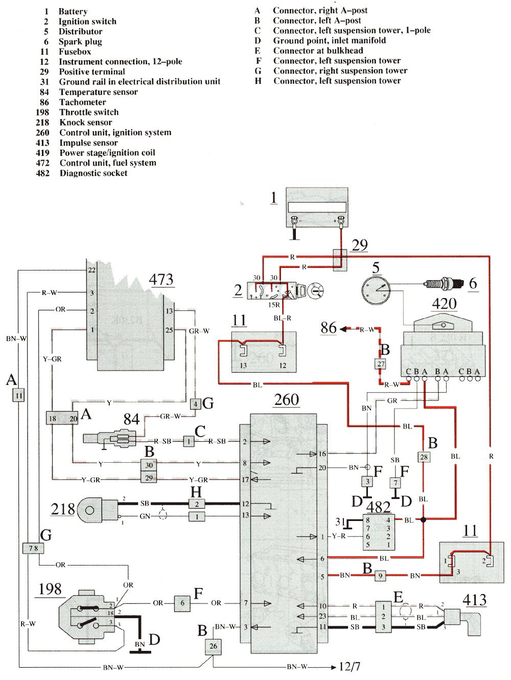
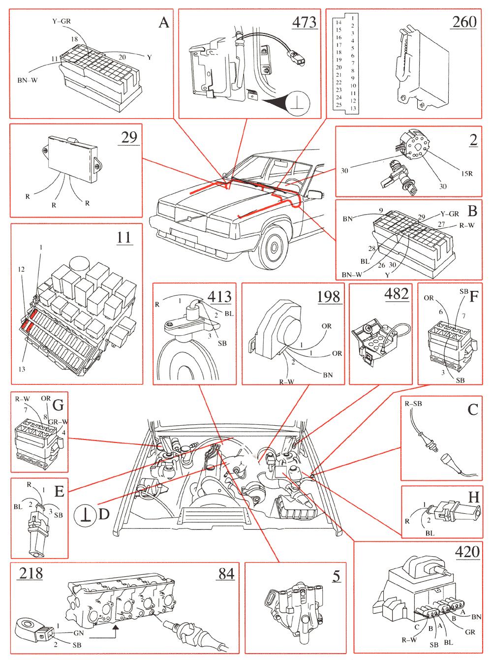
Powertrain Management: Electrical Diagrams Fuel Injection System
 1995 Volvo 940 L4-2.3L SOHC VIN 88 B230F Copyright 2009, ALLDATA 9.70 Page 1 Powertrain Management: Electrical Diagrams Fuel Injection System Wiring Diagram 1995 Volvo 940 L4-2.3L SOHC VIN 88 B230F Copyright
3/25 Switch, power sunroof 3/26 Control module, driver's seat 3/27 Control module, passenger's seat 3/28 Switch for heated driver's seat 3/29 Switch
 List of Components 1/1 Battery 2/1 Headlight relay with bulb failure sensor 2/2 Foglight relay 2/3 Regulator DIM-DIP 2/4 Intermittent wiper relay, windshield wipers 2/5 Relay, seat belt reminder/ignition
5/16/2017 ALLDATA Repair - Vehicle Information Volvo V L5-2.4L VIN 61 B5244S
 1/1 Battery 2/16 Relay, Intermittent Rear Window Wiping On/Off 2/17 Horn Relay 2/22 AC Relay 2/23 Fuel Pump Relay 2/29 Relay, Extended D1 Feed 2/30 X Feed Overload Relay 2/31 15-Feed Overload Relay 2/32
List of components 1:6
 List of components 1:6 1/1 Battery 2/16 Relay, rear window wiper 2/17 Relay, horn 2/22 Relay, climate control system 2/23 Relay, fuel pump 2/32 Main relay, engine management system 2/34 Relay, front fog
POWER SOURCE (Current Flow Chart)
") POWER SOURCE (Current Flow Chart) The chart below shows the route by which current flows from the battery to each electrical source (Fusible Link, Circuit Breaker, Fuse, etc.) and other parts. The next
POWER SOURCE (Current Flow Chart) The chart below shows the route by which current flows from the battery to each electrical source (Fusible Link, Circuit Breaker, Fuse, etc.) and other parts. The next
C915 - A147 Powertrain control module (PCM) C916 - A7 ABS control module
 C916 - A7 ABS control module") C915 - A147 Powertrain control module (PCM) C916 - A7 ABS control module C1152 - K11 Intermittent wiper relay, front C1153 - K1 Rear window heater relay C1154 - K18 ABS main relay C1155 - K25 ABS Pump
C915 - A147 Powertrain control module (PCM) C916 - A7 ABS control module C1152 - K11 Intermittent wiper relay, front C1153 - K1 Rear window heater relay C1154 - K18 ABS main relay C1155 - K25 ABS Pump
List of components 1:6
 List of components 1:6 1/1 Battery 1/1 Battery 2/14 Relay, glow plug unit 2/22 Relay, climate control system 2/32 Main relay, engine management system 2/33 Relay, fuel system 2/35 Starter motor relay 2/64
Position of Parts in Engine Compartment
 [1UZ FE] Position of Parts in Engine Compartment A 1 A/C Ambient Temp. Sensor E 4 Engine Coolant Temp. Sensor (Water Temp. Sensor A 2 A/C Dual Pressure SW and A/C High Pressure SW (for Cooling Fan)) A
Position of Parts in Engine Compartment
 ELECTRICAL WIRING ROUTING [5S FE] Position of Parts in Engine Compartment A 1 A/C Condenser Fan Motor E 4 Engine Coolant Temp. Sensor (EFI Water Temp. A 2 A/C Magnetic Clutch and Lock Sensor Sensor) A
CONFIGURATION DIAGRAMS
 80A-1 GROUP 80A CONFIGURATION DIAGRAMS CONTENTS OVERALL CONFIGURATION DIAGRAM...................... 80A-2 HOW TO READ CONFIGURATION DIAGRAMS.................... 80A-3 ENGINE COMPARTMENT......... 80A-4
ELECTRICAL COMPONENT LOCATOR
 ELECTRICAL COMPONENT LOCATOR 1988 Toyota Celica 1988 TOYOTA Celica Electrical Components ---------------------------------------------------------------------- BUZZERS, RELAYS & TIMERS ----------------------------------------------------------------------
G ELECTRICAL WIRING ROUTING
 2 6 G ELECTRICAL WIRING ROUTING [2JZ-GTE] Position of Parts in Engine Compartment A 1 A/C Ambient Temp Sensor A 2 A/C Condensor Fan Motor A 3 A/C Triple Pressure SW (A/C Dual and Single Pressure SW) A
2000 Volkswagen Jetta GL
 Fig. 8: Locating Battery Fuse Panel Fuses Courtesy of VOLKSWAGEN UNITED STATES, INC. FUSE IDENTIFICATION (BATTERY FUSE PANEL) Fuse No. Amp Circuits Protected Rating 162 Engine Codes 50 Secondary Air Injector
CONFIGURATION DIAGRAMS
 80-1 GROUP 80 CONFIGURATION DIAGRAMS CONTENTS CONFIGURATION DIAGRAMS......................... 80A SPLICE LOCATIONS................................. 80B 80A-2 GROUP 80A CONFIGURATION DIAGRAMS CONTENTS OVERALL
Position of Parts in Engine Compartment
 ELECTRICAL WIRING ROUTING [3S GTE] Position of Parts in Engine Compartment A 1 A/C Ambient Temp. Sensor D 1 Date Link Connector 1 (Check Connector) A 2 A/C Condenser Fan Motor D 2 Distributor A 4 A/C Magnetic
G ELECTRICAL WIRING ROUTING [1MZ-FE] Position of Parts in Engine Compartment
![G ELECTRICAL WIRING ROUTING [1MZ-FE] Position of Parts in Engine Compartment](/thumbs/87/97394184.jpg "G ELECTRICAL WIRING ROUTING [1MZ-FE] Position of Parts in Engine Compartment") G ELECTRICAL WIRING ROUTING [1MZ-FE] Position of Parts in Engine Compartment A 1 A/C Ambient Temp. Sensor A 2 A/C Condenser Fan Motor A 3 A/C Magnetic Clutch and Lock Sensor A 4 A/C Triple Pressure SW
G ELECTRICAL WIRING ROUTING [1MZ-FE] Position of Parts in Engine Compartment A 1 A/C Ambient Temp. Sensor A 2 A/C Condenser Fan Motor A 3 A/C Magnetic Clutch and Lock Sensor A 4 A/C Triple Pressure SW
BUZZERS, RELAYS & TIMERS
 BUZZERS, RELAYS & TIMERS 1997 MAZDA MX-5 Miata BUZZERS, RELAYS & TIMERS Location A/C Relay In right front of engine compartment, near radiator. See Fig. 1. Condenser Fan Relay In right front of engine
CONFIGURATION DIAGRAMS
 80A-1 GROUP 80A CONFIGURATION DIAGRAMS CONTENTS OVERALL CONFIGURATION DIAGRAM...................... 80A-2 HOW TO READ CONFIGURATION DIAGRAMS.................... 80A-3 ENGINE COMPARTMENT......... 80A-4
1991 TOYOTA Electrical Components MR2. evaporator. compartment. ARTICLE BEGINNING BUZZERS, RELAYS & TIMERS
 ELECTRICAL COMPONENT LOCATOR Article Text ARTICLE BEGINNING 1991 TOYOTA Electrical Components MR2 BUZZERS, RELAYS & TIMERS A/C Compressor Clutch Relay Under right side of dash, on evaporator. Circuit Opening
G ELECTRICAL WIRING ROUTING
 2 6 G ELECTRICAL WIRING ROUTING Position of Parts in Engine Compartment A1 A/C Front Magnetic Valve A3 A/C Magnetic Clutch A6 A/T Flud Temp. Sensor A7 ABS Actuator A8 ABS Actuator A10 ABS Speed Sensor
Layout Diagrams. Section CONTENTS. General Layout Diagram Floor / Roof Engine Compartment Door
 1-1 Section 1 Layout Diagrams CONTENTS General Layout Diagram...1-3 Engine Compartment...1-4 Engine / Transmission...1-6 Floor / Roof...1-16 Door...1-18 Boot Compartment...1-20 Instrument Panel...1-10
Passat Fitting Locations No. 208 / 1 Edition
 Sivu 1/11 Passat Fitting Locations No. 208 / 1 Edition 02.2007 Relay and fuse assignment From May 2002 Relay locations on 13 position additional relay carrier above relay plate 1 - Radiator fan relay -
Position of Parts in Engine Compartment
 ELECTRICAL WIRING ROUTING [5S FE] Position of Parts in Engine Compartment A 1 A/C Ambient Temp. Sensor D 1 Distributor A 2 A/C Condenser Fan Motor A 3 A/C Idle Up VSV E 1 ECT Solenoid A 4 A/C Magnet Clutch
CONNECTOR/GROUND/SPLICE LOCATION
 AN 8W-91 CONNECTOR/GROUND/SPLICE LOCATION 8W-91-1 8W-91 CONNECTOR/GROUND/SPLICE LOCATION TABLE OF CONTENTS page CONNECTOR/GROUND/SPLICE LOCATION DESCRIPTION...1 CONNECTOR/GROUND/SPLICE LOCATION DESCRIPTION
FUSE DETAILS. Fuse Details
 2003 Jaguar S-Type (X200) V8-4.2L Vehicle > Power and Ground Distribution > Fuse > Application and ID > Components FUSE DETAILS Fuse Details https://my.alldata.com/repair/#/repair/article/40444/component/1169/itype/389/nonstandard/1247914
G ELECTRICAL WIRING ROUTING
 G ELECTRICAL WIRING ROUTING Position of Parts in Engine Compartment A 1 A/C Ambient Temp. Sensor A 2 A/C Condenser Fan Motor A 3 A/C Magnetic Clutch and Lock Sensor A 4 A/C Triple Pressure SW (A/C Dual
POWER SOURCE (Current Flow Chart)
") The chart below shows the route by which current flows from the battery to each electrical source (Fusible Link, Circuit Breaker, Fuse, etc.) and other parts. The next page and following pages show the
The chart below shows the route by which current flows from the battery to each electrical source (Fusible Link, Circuit Breaker, Fuse, etc.) and other parts. The next page and following pages show the
G ELECTRICAL WIRING ROUTING
 G ELECTRICAL WIRING ROUTING Position of Parts in Engine Compartment A 1 A/C Condenser Fan Motor A 2 A/C Magnetic Clutch and Lock Sensor A 3 A/C Triple Pressure SW (A/C Dual and Signal Pressure SW) A 4
FUSES & CIRCUIT BREAKERS
 FUSES & CIRCUIT BREAKERS FUSES & CIRCUIT BREAKERS 1989-95 FUSES & CIRCUIT BREAKERS Ford Motor Co. INTERIOR FUSE PANEL IDENTIFICATION (1983-88 MODELS) On all models, the fuse panel is located under the
CONFIGURATION DIAGRAMS
 GROUP 80 CONFIGURATION DIAGRAMS CONTENTS OVERALL CONFIGURATION DIAGRAM...................... 80-2......... 80-3 .. 80-3 .. 80-5 ...... 80-7 INSTRUMENT PANEL............ 80-9 FLOOR
BUZZERS, RELAYS & TIMERS
 ELECTRICAL COMPONENT LOCATOR 1994 ELECTRICAL COMPONENT LOCATION Mazda Electrical s BUZZERS, RELAYS & TIMERS BUZZERS, RELAYS & TIMERS LOCATION ABS s Motor Relay On top of ABS pump, on right rear corner
SOUL GDI REPAIR AND MAINTENANCE
 SOUL 2013-1.6 GDI REPAIR AND MAINTENANCE (First Numbers are page number within section - Numbers in parenthesis are overall document page) GENERAL INFORMATION (23 PAGES) 01-07 (01-07): Identification Number
SECTION 9A BODY WIRING SYSTEM
 SECTION 9A BODY WIRING SYSTEM Caution: Disconnect the negative battery cable before removing or installing any electrical unit or when a tool or equipment could easily come in contact with exposed electrical
G ELECTRICAL WIRING ROUTING [2ZZ GE] Position of Parts in Engine Compartment
![G ELECTRICAL WIRING ROUTING [2ZZ GE] Position of Parts in Engine Compartment](/thumbs/82/84806793.jpg "G ELECTRICAL WIRING ROUTING [2ZZ GE] Position of Parts in Engine Compartment") G ELECTRICAL WIRING ROUTING [2ZZ GE] Position of Parts in Engine Compartment A 1 A/C Magnetic Clutch A 2 ABS Speed Sensor Front LH A 3 ABS Speed Sensor Front RH A 4 Airbag Sensor Front LH A 5 Airbag Sensor
G ELECTRICAL WIRING ROUTING [2ZZ GE] Position of Parts in Engine Compartment A 1 A/C Magnetic Clutch A 2 ABS Speed Sensor Front LH A 3 ABS Speed Sensor Front RH A 4 Airbag Sensor Front LH A 5 Airbag Sensor
G ELECTRICAL WIRING ROUTING
 G ELECTRICAL WIRING ROUTING Position of Parts in Engine Compartment A 1 A/C Condenser Fan Motor A 2 A/C Magnetic Clutch and Lock Sensor A 3 A/C Triple Pressure SW (A/C Dual and Single Pressure SW) A 4
List of components 1:9
 List of components 1:9 1/1 Battery 1/1 Battery 2/22 Relay, climate control system 2/32 Main relay, engine management system 2/35 Relay, starter motor 2/64 Auxiliary light relay 2/64 Auxiliary light relay
CIRCUIT DIAGRAMS GROUP CONTENTS HOW TO READ CIRCUIT DIAGRAMS BACKUP LIGHT TURN SIGNAL LIGHT AND HAZARD WARNING LIGHT...
 90-1 GROUP 90 CIRCUIT DIAGRAMS CONTENTS HOW TO READ CIRCUIT DIAGRAMS................................. 90-4 JUNCTION BLOCK.............. 90-10............. 90-12 CENTRALIZED JUNCTION........ 90-18 POWER
Audi A4 Current Flow Diagram No. 44 / 1 Edition
 Page 1 of 16 Audi A4 Current Flow Diagram No. 44 / 1 Edition 05.2003 1.8 l - Fuel injection engine (110 kw - Motronic - 4 cylinder), engine code AVJ from model year 2002 1.8 l - Fuel injection engine (120
IDENTIFICATION COMPONENT LOCATION MENU
 WIRING DIAGRAMS 1993 Mitsubishi Diamante 1993 WIRING DIAGRAMS Mitsubishi Wiring Diagrams Mitsubishi; Diamante IDENTIFICATION COMPONENT LOCATION MENU COMPONENT LOCATIONS TABLE Component Figure No. (Location)
1997 Volvo 850 GLT. Fig. 2: Removing Drive Shaft, Engine Mount Bolt & Torque Arm (5-Cylinder) Courtesy of VOLVO CARS OF NORTH AMERICA.
 Courtesy of VOLVO CARS OF NORTH AMERICA.") Fig. 2: Removing Drive Shaft, Engine Mount Bolt & Torque Arm (5-Cylinder) 4. Remove front exhaust pipe nuts and springs. Remove front exhaust pipe bolts. Disconnect speedometer. Remove engine mounting
Fig. 2: Removing Drive Shaft, Engine Mount Bolt & Torque Arm (5-Cylinder) 4. Remove front exhaust pipe nuts and springs. Remove front exhaust pipe bolts. Disconnect speedometer. Remove engine mounting
List of components 1:7
 List of components 1:7 1/1 Battery 2/16 Relay, rear window wiper 2/17 Relay, horn 2/22 Relay, climate control system 2/31 Relay, 15-feed 2/32 Main relay, engine management system 2/35 Relay, starter motor
G ELECTRICAL WIRING ROUTING [5VZ FE] TOYOTA TACOMA (EWD517U) Position of Parts in Engine Compartment
![G ELECTRICAL WIRING ROUTING [5VZ FE] TOYOTA TACOMA (EWD517U) Position of Parts in Engine Compartment](/thumbs/82/86578697.jpg "G ELECTRICAL WIRING ROUTING [5VZ FE] TOYOTA TACOMA (EWD517U) Position of Parts in Engine Compartment") G ELECTRICAL WIRING ROUTING [5VZ FE] Position of Parts in Engine Compartment A 5 A/C Magnetic Clutch A 7 A/T Oil Temp. Sensor A22 ABS Actuator with ECU A23 Air Fuel Ratio Sensor (Bank 1 Sensor 1) A24 ADD
G ELECTRICAL WIRING ROUTING [5VZ FE] Position of Parts in Engine Compartment A 5 A/C Magnetic Clutch A 7 A/T Oil Temp. Sensor A22 ABS Actuator with ECU A23 Air Fuel Ratio Sensor (Bank 1 Sensor 1) A24 ADD
Fuse and Relay Information
 11-1 Fuse and Relay Information Battery Junction Box (BJB) (14A003) PCM power diode Air suspension compressor Front fog lamp cutoff Police power Traction control indicator A/C clutch Fuel pump C1300 C1008
IDENTIFICATION COMPONENT LOCATION MENU
 Article Text ARTICLE BEGINNING 1992 WIRING DIAGRAMS Chrysler/Mitsubishi Wiring Diagrams Dodge; Colt Eagle; Summit Mitsubishi; Mirage IDENTIFICATION COMPONENT LOCATION MENU COMPONENT LOCATIONS TABLE Component
ARTICLE BEGINNING SAFETY PRECAUTION BUZZERS, RELAYS & TIMERS ELECTRICAL COMPONENT LOCATION Volkswagen Electrical Components - 2.0L 4-Cyl.
 Article Text ARTICLE BEGINNING 1996 ELECTRICAL COMPONENT LOCATION Volkswagen Electrical Components - 2.0L 4-Cyl. Cabrio, Golf III, Jetta III SAFETY PRECAUTION WARNING: When working on vehicles equipped
Fuses FUSE BOX LOCATIONS. Engine compartment fuse box
 Fuses FUSE BOX LOCATIONS Engine compartment fuse box 1 2 E90971 Remove the plastic cover by pressing the tabs. The fuse values and locations and the circuits protected are shown on the plastic cover. 3
LIST OF COMPONENTS (SECTION 1) B001: mixed bridge block 1 B002: mixed bridge block 2 B003: mixed bridge block 3 BB00: battery BB01: battery assembly
 B001: mixed bridge block 1 B002: mixed bridge block 2 B003: mixed bridge block 3 BB00: battery BB01: battery assembly") LIST OF COMPONENTS (SECTION 1) B001: mixed bridge block 1 B002: mixed bridge block 2 B003: mixed bridge block 3 BB00: battery BB01: battery assembly (rear) BB02: battery assembly (lower front) ВВ0З: battery
LIST OF COMPONENTS (SECTION 1) B001: mixed bridge block 1 B002: mixed bridge block 2 B003: mixed bridge block 3 BB00: battery BB01: battery assembly (rear) BB02: battery assembly (lower front) ВВ0З: battery
Fuses FUSE BOX LOCATIONS. Engine compartment fuse box
 FUSE BOX LOCATIONS Engine compartment fuse box 1 2 LAN2333 Remove the plastic cover by pressing the tabs. The fuse values and locations and the circuits protected are shown on the plastic cover. LAN2332
L PART NUMBER OF CONNECTORS
 L PART NUMBER OF CONNECTORS Code Part Name Part Number Code Part Name Part Number A 1 A/C Ambient Temp. Sensor 90980-11070 B15 Blower Motor Controller (Rear) 90980-11136 A 2 A/C Magnetic Clutch 90980-11271
BATTERY - HEADLIGHTS Special notes 80
 BATTERY - HEADLIGHTS Special notes 80 BATTERY - HEADLIGHTS Special notes 80 BATTERY - HEADLIGHTS Lens units 80 BATTERY - HEADLIGHTS Lens units 80 BATTERY - HEADLIGHTS Lens units 80 BATTERY - HEADLIGHTS
HOT IN START OR RUN JUNCTION BLOCK (BEHIND LEFT SIDE OF DASH)
") of //0 : PM Vehicle Reference: WIRING DIAGRAMS BODY CONTROL MODULES 00 Mitsubishi Diamante.L Eng VR-X Fig : Assist ECU Circuit HOT IN START OR RUN (BEHIND (ON LEFT FRONT FENDER) HOT IN ACC OR RUN (BEHIND
of //0 : PM Vehicle Reference: WIRING DIAGRAMS BODY CONTROL MODULES 00 Mitsubishi Diamante.L Eng VR-X Fig : Assist ECU Circuit HOT IN START OR RUN (BEHIND (ON LEFT FRONT FENDER) HOT IN ACC OR RUN (BEHIND
Volkswagen Cabriolet DIY Guide Relay/Fuse Diagrams & Electrical System
 Volkswagen Cabriolet DIY Guide Relay/Fuse Diagrams & Electrical System Notes: 1980-1982 cars use ceramic fuses! 1980-1982 cars had a recall for the fuel pump relay. These cars should have a relay bypass
ÄÄÄÄÄÄÄÄÄÄÄÄÄÄÄÄÄÄÄÄÄÄÄÄÄÄÄÄÄÄÄÄÄÄÄÄÄÄÄÄÄÄÄÄÄÄÄÄÄÄÄÄÄÄÄÄÄÄÄÄÄÄÄÄÄÄÄÄÄÄ
 ELECTRICAL COMPONENT LOCATOR Article Text 1989 Toyota MR2 For RSe 7 HotRod Lane C'Ville VA 22901 Copyright 1997 Mitchell International Monday, May 20, 2002 12:36AM ARTICLE BEGINNING 1989 TOYOTA MR2 Electrical
JLK-019. Jaguar Dealer. After renewing a fuse have the circuit checked by
 4-12 Roadside emergency service s and Boxes failure is signalled by an inoperative circuit. Do not fit a new fuse if damage to the wiring is found; contact a Jaguar Dealer. After renewing a fuse have the
PART - RETAIL SHOP C900 DAVID'S [78-94] 9000 PRICE [84-98] LIST NG900 [94-98] OG9-3 [99-03] 9-3SS [03-11] A/C Compressor
![PART - RETAIL SHOP C900 DAVID'S [78-94] 9000 PRICE [84-98] LIST NG900 [94-98] OG9-3 [99-03] 9-3SS [03-11] A/C Compressor](/thumbs/95/124876646.jpg "PART - RETAIL SHOP C900 DAVID'S [78-94] 9000 PRICE [84-98] LIST NG900 [94-98] OG9-3 [99-03] 9-3SS [03-11] A/C Compressor") PART - RETAIL SHOP C900 DAVID'S [78-94] 9000 PRICE [84-98] LIST NG900 [94-98] OG9-3 [99-03] 9-3SS [03-11] A/C Compressor 150-250 150-250 150-250 150-250 150-250 A/C Condensor A/C Miscellaneous Parts A/C
PART - RETAIL SHOP C900 DAVID'S [78-94] 9000 PRICE [84-98] LIST NG900 [94-98] OG9-3 [99-03] 9-3SS [03-11] A/C Compressor 150-250 150-250 150-250 150-250 150-250 A/C Condensor A/C Miscellaneous Parts A/C
1 of 15 C:\Users\sny\Downloads\2019 Used Parts Price List.ods
 PART - RETAIL SHOP C900 DAVID'S [78-94] 9000 PRICE [84-98] LIST NG900 [94-98] OG9-3 [99-03] 9-3SS [03-11] A/C Compressor 150-250 150-250 150-250 150-250 150-250 A/C Condensor A/C Miscellaneous Parts A/C
Fuses. Fuses FUSE BOX LOCATIONS
 FUSE BOX LOCATIONS 206 When a fuse box lid is removed, take care to protect the box from moisture, and refit the lid at the earliest opportunity. Engine compartment - fuse box access: 1. Remove the two
Acura Plus Comprehensive & Major Component Coverage
 Acura Plus Comprehensive & Major Component Coverage ENGINE Cylinder block and all internal parts Cylinder heads and all internal parts Engine mounts Engine seals and gaskets Flywheel Intake and exhaust
(1,1) Index 14 北米Model "A1330BE-B" EDITED: 2017/ 11/ 30
 Index 14 北米Model A1330BE-B EDITED: 2017/ 11/ 30") Index 14 14-2 Index A Abbreviation... 3 ABS (Anti-lock Brake System)... 7-33 Warning light... 3-20 Access key fob... 2-3 Warning light... 3-25 Accessories... 11-37 Accessory power outlet... 6-7 Air cleaner
Index 14 14-2 Index A Abbreviation... 3 ABS (Anti-lock Brake System)... 7-33 Warning light... 3-20 Access key fob... 2-3 Warning light... 3-25 Accessories... 11-37 Accessory power outlet... 6-7 Air cleaner
Supercharged MK1 MR2 Part Diagrams
 Supercharged MK1 MR2 Part Diagrams Created by: Charles K. (ckowalc) 1 Table of Contents PART DIAGRAM PAGE ACCELERATOR LINK 9 AIR CLEANER 10 AIR CLEANER 4AGZE 11 ALTERNATOR 4AGZE 12 ANTENNA 13 ARMREST &
Onboard power supply management
 Onboard power supply management The onboard power supply J519 Functions of onboard power supply control unit Until now s and relays functioned at different locations in the vehicle. In the onboard power
Frame contained PDF file, click here to view
 Cars with SRS Contents Fuses 1:2, 2:2 Fuses, Diesel 1:4, 2:4, 3:4, 4:4 Relays in positions 210-211 Engine management system relays, Diesel Electrical distribution Electrical distribution, Diesel Ground
Fuse and Relay Information
 11 1 Fuse and Relay Information Central Junction Box (CJB) (14A067) PCM power Trailer tow, battery charge Starter (11450) Blower motor Rear window defrost F2.602 C270p F2.101 F2.107 F2.102 F2.108 F2.601
HOW TO USE SYSTEM WIRING DIAGRAMS
 HOW TO USE SYSTEM WIRING DIAGRAMS 1998 Pontiac Bonneville GENERAL INFORMATION Using Wiring Diagrams All Models INTRODUCTION This CD obtains wiring diagrams and technical service bulletins, containing wiring
Diagnostic Trouble Code (DTC) memory, checking and erasing
 memory, checking and erasing") Page 1 of 49 01-12 Diagnostic Trouble Code (DTC) memory, checking and erasing Check DTC Memory (function 02) - Connect VAS5051 tester Page 01-7 and select vehicle system "01 - Engine electronics". Engine
Page 1 of 49 01-12 Diagnostic Trouble Code (DTC) memory, checking and erasing Check DTC Memory (function 02) - Connect VAS5051 tester Page 01-7 and select vehicle system "01 - Engine electronics". Engine
COMPONENT LOCATIONS GROUP CONTENTS FUSIBLE LINK, FUSE AND IOD OR STORAGE CONNECTOR RELAY OTHER DEVICES...
 70-1 GROUP 70 COMPONENT LOCTIONS CONTENTS RELY........................ 70-2 OTHER DEVICES............... 70-3 CONTROL UNIT................. 70-4 INSPECTION TERMINL......... 70-7 SENSOR.......................
Part 8 SPECIFICATIONS
 Part 8 SPECIFICATIONS Dimensions and weight Engine Fuel Service specifications Tires Fuses Dimensions and weight P195/70R 14 tire Overall length 4783 (188.3) Overall width 1780 (70.1) Overall height 1416
OPERATING INSTRUCTIONS DOCUMENT
 OPERATING INSTRUCTIONS DOCUMENT 1. BREAKDOWN OF THE FUNCTION INTO THREE DIAGRAMS: * Schematic diagram. * Wiring diagram. * Installation diagram. 2. CONSTITUTION OF THE DIAGRAMS: Schematic diagram: supplies
1. CAUTIONS WHEN WORKING ON ELECTRICAL UNITS
 841006 013 Fuse and relay 841006 1. CAUTIONS WHEN WORKING ON ELECTRICAL UNITS Remove the negative battery cable from the battery in advance when working on electrical units. Make sure to turn "OFF" the
ON-BOARD DIAGNOSTICS II SYSTEM. 5. Specified Data. Signal (V) Ignition SW ON (Engine OFF)
 Ignition SW ON (Engine OFF)") 1. ENGINE CONTROL MODULE (ECM) I/O SIGNAL OBD0092A Crankshaft Camshaft Mass air flow Throttle Signal (+) 8 0 7 +7 Sensor output waveform Signal ( ) 29 0 0 Shield 54 0 0 Signal (+) 7 0 7 +7 Sensor output
1. ENGINE CONTROL MODULE (ECM) I/O SIGNAL OBD0092A Crankshaft Camshaft Mass air flow Throttle Signal (+) 8 0 7 +7 Sensor output waveform Signal ( ) 29 0 0 Shield 54 0 0 Signal (+) 7 0 7 +7 Sensor output
CIRCUIT DIAGRAMS GROUP CONTENTS HOW TO READ CIRCUIT DIAGRAMS VANITY MIRROR LIGHT JUNCTION BLOCK...
 90-1 GROUP 90 CONTENTS HOW TO READ................................. 90-4 JUNCTION BLOCK.............. 90-10 JOINT CONNECTOR............. 90-12 CENTRALIZED JUNCTION........ 90-13 POWER DISTRIBUTION SYSTEM..
GENERAL INFORMATION Using Wiring Diagrams. All Models
 Article Text ARTICLE BEGINNING GENERAL INFORMATION Using Wiring Diagrams All Models INTRODUCTION Mitchell obtains wiring diagrams and technical service bulletins, containing wiring diagram changes from
Diagnostic Trouble Code (DTC) List - Vehicle
 List - Vehicle") Document ID# 850406 2002 Pontiac Firebird Diagnostic Trouble Code (DTC) List - Vehicle DTC DTC 021 and/or 031 DTC 022 and/or 032 DTC 023 or 033 DTC 24/34 DTC 025 and/or 035 DTC 041 DTC 042 DTC 043 DTC
Document ID# 850406 2002 Pontiac Firebird Diagnostic Trouble Code (DTC) List - Vehicle DTC DTC 021 and/or 031 DTC 022 and/or 032 DTC 023 or 033 DTC 24/34 DTC 025 and/or 035 DTC 041 DTC 042 DTC 043 DTC
ARTICLE BEGINNING COMPONENT LOCATION MENU Wiring Diagrams Audi
 Article Text ARTICLE BEGINNING 1990 Wiring Diagrams Audi 200 COMPONENT LOCATION MENU COMPONENT LOCATIONS TABLE ÄÄÄÄÄÄÄÄÄÄÄÄÄÄÄÄÄÄÄÄÄÄÄÄÄÄÄÄÄÄÄÄÄÄÄÄÄÄÄÄÄÄÄÄÄÄÄÄÄÄÄÄÄÄÄÄÄÄÄÄ Component (Figure No.) Location
Buckle SW Rear RH C 1 Camshaft Position Sensor Camshaft Timing Oil Control Valve RH. Crankshaft Position Sensor
 A 1 A/C Ambient Temp. Sensor 90980 11070 A 2 A/C Magnetic Clutch and ock Sensor 90980 11016 A 3 A/C Pressure Sensor 90980 10845 A 4 A/C Solenoid 90980 10901 A 5 ABS & TRAC & VSC Actuator 90980 11451 A
Fuse/Relay Information
 BD 10/24/91 kd 11/12 smk 11/14/91 MC 4/8/92 bd 4/14/92 92 PRELUDE /Relay Information Under-hood /Relay Box 47 46 45 44 43 42 41 40 39 31 49 48 51 50 37 36 35 34 33 32 C941 (To ABS motor relay) 38 C942
Diesel Technology: Electrical and Electronic Systems
 Diesel Technology: Electrical and Electronic Systems NATEF Crosswalk The following NATEF Electrical/Electronic Systems tasks (rev. 2001) are covered in this publication. The chart shows where each task
5. Engine Control Module (ECM) I/O Signal
 I/O Signal") 5. A: ELECTRICAL SPECIFICATION B134 B135 B136 B137 17 16 15 14 13 12 11 10 9 8 27 26 25 24 23 22 21 20 19 18 34 33 32 31 30 29 28 19 18 17 16 15 14 13 12 11 10 9 8 27 26 25 24 23 22 21 20 35 34 33 32 31
5. A: ELECTRICAL SPECIFICATION B134 B135 B136 B137 17 16 15 14 13 12 11 10 9 8 27 26 25 24 23 22 21 20 19 18 34 33 32 31 30 29 28 19 18 17 16 15 14 13 12 11 10 9 8 27 26 25 24 23 22 21 20 35 34 33 32 31
Transporter Current Flow Diagram No. 80 / 1 Edition
 Side 1 av 13 Transporter Current Flow Diagram No. 80 / 1 Edition 05.2003 2.5 l/65 kw direct injection turbo diesel, engine code AJT From May 1999 2.5 l/75 kw direct injection turbo diesel, engine codes
rear RH side of engine compartment in E-Box AGS transmission control module Component connector (9-pin, Blue), AGS transmission control module
, AGS transmission control module") rear RH side of engine compartment in E-Box A7000 X70001 AGS transmission control module Component connector (9-pin, Blue), AGS transmission control module on RH side of transmission S8532 Automatic transmission
rear RH side of engine compartment in E-Box A7000 X70001 AGS transmission control module Component connector (9-pin, Blue), AGS transmission control module on RH side of transmission S8532 Automatic transmission
COOLING FAN DEFOGGERS HORN POWER ANTENNA POWER DOOR LOCKS POWER MIRRORS POWER SEATS POWER WINDOWS RADIO 2.3L. Fig. 1: 2.3L Turbo, Cooling Fan Circuit
 COOLING FAN 2.3L Fig. 1: 2.3L Turbo, Cooling Fan Circuit DEFOGGERS Fig. 2: Defogger Circuit, W/ Electronic ATC Fig. 3: Defogger Circuit, W/O Electronic ATC HORN Fig. 4: Horn Circuit POWER ANTENNA Fig.
TOYOTA HILUX FACTORY SERVICE, REPAIR, SHOP MANUAL - HILUX VIGO - YEARS MANUAL -!
 Instant Manual Download TOYOTA HILUX 2005 2006 2007 2008 2009 FACTORY SERVICE, REPAIR, SHOP MANUAL - HILUX VIGO - YEARS 05 06 07 08 09 - MANUAL -! Download Here TOYOTA HILUX 2005-2009 (2005 2006 2007 2008
Telephone: Fax: VAT Registration No.:
 Telephone: Fax: VAT Registration No.: K143 AC compressor clutch relay X88 AC connector S63 AC refrigerant pressure switch S341 AC refrigerant triple pressure switch A16 Anti-lock braking system (ABS) control
Diagnostic Trouble Code (DTC) table
 table") Page 1 of 40 01-19 Diagnostic Trouble Code (DTC) table Note: When malfunctions occur in monitored sensors or components, Diagnostic Trouble Codes (DTCs) are stored in DTC memory with a description of the
Page 1 of 40 01-19 Diagnostic Trouble Code (DTC) table Note: When malfunctions occur in monitored sensors or components, Diagnostic Trouble Codes (DTCs) are stored in DTC memory with a description of the
FUSES & CIRCUIT BREAKERS
 FUSES & CIRCUIT BREAKERS FUSES & CIRCUIT BREAKERS 1995 General Motors Corp. FUSES & CIRCUIT BREAKERS FUSE PANEL IDENTIFICATION (INSTRUMENT PANEL) Friday, November 27, 2009 5:05:35 5:05:39 PM Page 1 2005
1994 Cadillac Seville STS
 Fig. 2: High-Current Fuse Panel ID (1994-95 Seville) L/H Maxi-Fuse & Circuit Breaker Identification 1-50 Amp STRG 1-2 Retained Accessory Power (Radio/Wipers), Starter, Trunk Comp Fuses 8 & 9 2-60 Amp BODY
WIRING DIAGRAM 1. General Description
 Page 1. General Description...1 2. Wiring Diagram...10 (1) POWER SUPPLY ROUTING...10 (2) ENGINE CONTROL SYSTEM (SOHC)...14 (3) ENGINE CONTROL SYSTEM (2.0 DOHC NA)...18 (4) ENGINE CONTROL SYSTEM (2.5 )...22
2.8 Liter VR6 2V Fuel Injection & Ignition, Engine Code(s): AAA m.y
: AAA m.y") 2.8 Liter VR6 2V Fuel Injection & Ignition, Engine Code(s): AAA m.y. 1996-1997 01 - On Board Diagnostic (OBD) On Board Diagnostic (OBD II) Malfunction Indicator Lamp (MIL) On Board Diagnostic (OBD II),
2.8 Liter VR6 2V Fuel Injection & Ignition, Engine Code(s): AAA m.y. 1996-1997 01 - On Board Diagnostic (OBD) On Board Diagnostic (OBD II) Malfunction Indicator Lamp (MIL) On Board Diagnostic (OBD II),
Audi A3 Current Flow Diagram No. 75 / 1 Edition Audi A3 (1,8 l litre fuel injection engine, 110 kw, Motronic, 4-cylinder) engine codes AQA
 engine codes AQA") Strona 1 z 10 Audi A3 Current Flow Diagram No. 75 / 1 Edition 09.1999 Audi A3 (1,8 l litre fuel injection engine, 110 kw, Motronic, 4-cylinder) engine codes AQA From model year 1999 Audi A3 (1,8 l litre
Strona 1 z 10 Audi A3 Current Flow Diagram No. 75 / 1 Edition 09.1999 Audi A3 (1,8 l litre fuel injection engine, 110 kw, Motronic, 4-cylinder) engine codes AQA From model year 1999 Audi A3 (1,8 l litre
2009 Model year NPR, NPR HD Gas Electrical Symbols. Symbol Meaning Symbol Meaning Symbol Meaning
 2009 Model year NPR, NPR HD Gas Electrical Symbols 14.1 Symbol Meaning Symbol Meaning Symbol Meaning Fuse Electronic Parts Coil (Inductor), Solenoid Magnetic Valve Fusible Link Resistor Relay Fusible Link
ARTICLE BEGINNING FUSES & CIRCUIT BREAKERS * PLEASE READ FIRST * ALL BUT JETTA ( ) Fuses & Circuit Breakers Volkswagen ELECTRICAL
 Fuses & Circuit Breakers Volkswagen ELECTRICAL") Article Text ARTICLE BEGINNING Fuses & Circuit Breakers 1987-96 Volkswagen ELECTRICAL FUSES & CIRCUIT BREAKERS * PLEASE READ FIRST * The fuse panel is located under the left side of the dash board by the
Article Text ARTICLE BEGINNING Fuses & Circuit Breakers 1987-96 Volkswagen ELECTRICAL FUSES & CIRCUIT BREAKERS * PLEASE READ FIRST * The fuse panel is located under the left side of the dash board by the
INSTRUCTIONS. 20 Circuit Wiring Kit Instructions October 2009, Speedway Motors, Inc.
 1 MAIN FUSE PANEL The main fuse panel harness s designed to be mounted under the dash a the firewall in an area close to the steering column. The enclosed representation of the main dash harness shows
AD07.61-P-4000AC ME-SFI fuel injection and ignition system (ME), DTC memory Possible cause Note Fault code description
, DTC memory Possible cause Note Fault code description") Page 1 of 11 AD07.61-P-4000AC fuel injection and ignition system (ME), DTC memory 14.6.00 ENGINE 112.942 as of 1.6.00 ENGINE 112.970 All tests of the electrical system of the fuel injection system on engine
Page 1 of 11 AD07.61-P-4000AC fuel injection and ignition system (ME), DTC memory 14.6.00 ENGINE 112.942 as of 1.6.00 ENGINE 112.970 All tests of the electrical system of the fuel injection system on engine
headlights [H only] dip switch hi beam flasher pillar interior lights rear interior panel switch C/D cubby A B boot map light LED strip
![headlights [H only] dip switch hi beam flasher pillar interior lights rear interior panel switch C/D cubby A B boot map light LED strip](/thumbs/74/70768506.jpg "headlights [H only] dip switch hi beam flasher pillar interior lights rear interior panel switch C/D cubby A B boot map light LED strip") to Alpine unit exterior lights [S or H or F] FUSE BOX LIGHTS ENGINE ACC reverse light, brake Note: diode (6a 50v) prevents triggering of Alpine backup camera when brake light is closed brake L tail plate
to Alpine unit exterior lights [S or H or F] FUSE BOX LIGHTS ENGINE ACC reverse light, brake Note: diode (6a 50v) prevents triggering of Alpine backup camera when brake light is closed brake L tail plate
Henry's Auto Parts, LLC
 Item Name Price ABS Unit $33.99 AC Compressor $34.99 AC Compressor Clutch $29.99 AC Condensor $19.99 AC Evaporator $16.99 AC Evaporator Housing $16.99 AC Receiver Drier $12.99 Air Cleaner $12.99 Air Conditioner
Audi A4 Current Flow Diagram No. 4 / 1 Edition
 Стр. 1 из 11 Audi A4 Current Flow Diagram No. 4 / 1 Edition 10.2001 Audi A4 (1.8 litre fuel injection engine, 110 kw, Motronic (5-valve/turbo), 4-cylinder), engine codes APU/ANB From model year 2000 Audi
Symptom Suspected Area See page Ignition switch is not set to each position. 11.Ignition switch BE 14
 BE2 BODY ELECTRICAL PROBLEM SYMPTOMS TABLE IGNITION SWITCH AND KEY UNLOCK WARNING SWITCH BE0ON18 Ignition switch is not set to each position. 11.Ignition switch BE14 Key unlock warning system does not
PRICE LIST ITEM PRICE $ CORE
 A/C Clutch $20.00 A/C Compressor $35.00 $10.00 A/C Condenser $25.00 $5.00 A/C Evaporator $15.00 A/C Hose(S) $15.00 Accelerator Cable $10.00 Air Bag $30.00 Air Bag Sensor $10.00 Air Cleaner $15.00 Air Filter
Troubleshooting Self-diagnostic Procedures
 Self-diagnostic Procedures I. When the Malfunction Indicator Lamp (MIL) has been reported on, do the following: 1. Connect the Service Check Connector terminals with a jumper wire as shown. (The 2P Service
TOYOTA STARLET EP82. Wiring connections, Connector IDs & Loom Layouts. Rev 1.2 Last Updated October 2011
 TOYOTA STARLET EP8 Wiring connections, Connector IDs & Loom Layouts Rev. Last Updated October 0 Author & Copyright : Alan Mears Location : Perth, Western Australia Contact Email : alan@mearcat.com.au Online