Aero-East-Europe d.o.o. SILA 450C SPARE PARTS CATALOG
|
|
|
- Dorothy Bell
- 5 years ago
- Views:
Transcription

1 Aero-East-Europe d.o.o. SILA 450C SPARE PARTS CATALOG

2 ADRESS: Aerodromska BB Kraljevo Serbia PHONE: 063/ FAX: 036/ MAIL: INTRODUCTION In front of you is the first spare parts catalog of the Aero East Europe Company. The purpose of this parts catalog is for identification of all replacement parts of SILA 450C airplane. Using of this catalog is allowed only for Aero East Europe personnel and authorized dealers. Copying and reproduction of this parts catalog is prohibited. THE STRUCTURE OF THE PARTS CATALOG Parts catalog is divided into five major sections which are: Fuselage Empennage Wings Landing gear Fuel system Each sub section of the airplane contains data for every part of an subassembly such as position in the assembly, part s name and bar code, description, price and image. The structure of the catalog is illustrated in the figure 1. Position Name/B ar code Major assembly Subassembly Part listing Descript ion Price Picture Figure 1: The structure scheme of the part catalog PARTS IDENTIFICATION For the identification of a specific part, one should complete next steps, as follows: 1. According to figure 2 (Complete airplane) find the section of your interest 2. Turn to table of contents and find the section. Note that each section is divided into several different sub-sections HARDWARE Hardware Such as nuts, bolts, screws, etc. those who are available as commercial items, usually is not supplied by Aero East Europe. The parts listing will contain those items of attaching hardware required for main assemblies and installations. All hardware must be in aeronautical standard with proper quality. OPTIONAL EQUIPMENT Optional equipment depends from customer request, and is different for each particular model. Under the optional equipment there are GPS navigation, GYRO-directional, G meter, etc. 3. Find the corresponding sub-section. The sub-section contains a figure of the subassembly with labeled parts 4. In the parts listing, look for the corresponding part number for the complete description of your part. 1


3 INTRODUCTION METHOD FOR PARTS ORDERING For ordering of a specific part one should provide the part s name, bar code and / or part s identification, with the respect to the part s identification procedure, and the parts listing. THE WAYS FOR ORDERING PARTS Ordering by the telephone 036/ Ordering by fax 036/ Ordering by aeroeasteurope@gmail.com For any additional information please contact us at: 036/ Aero East Europe d.o.o. Technical Department 2

.")


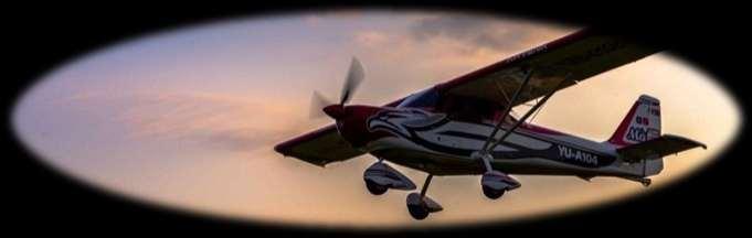
4 AERO EAST EUROPE D.O.O. Aero East Europe was founded in Assembling of the airplanes began in Italy where, during , 30 airplanes were assembled, after which the entire production was transferred to Kraljevo Serbia. In Serbia, in cooperation with the Faculty of Mechanical Engineering in Belgrade, and Kraljevo, the company continues to produce airplanes. Until now over 100 airplanes were produced, and in the same time a new airplane was designed and manufactured, the SILA 450 C (Serbian Industry of Light Aircraft). In the absence of the regulation for construction of ultra-light airplanes in Serbia, Aero East Europe was forced to comply with the requirements for production of general aviation, which is the JAR Part 21, according to which all airplanes are made using certified metal alloys and steel, aluminum and Cr Mo. The airplane from the SILA series, the SILA 450 C (C stands for Cruise) is the easiest of this category and is certified according to German LTF-UL airworthiness requirements, the most restrictive standard for this category of airplanes. SILA 450C is also certified in France. Each model of the factory Aero East Europe is manufactured according to VLA standards, from certified aeronautical material, from the easiest SILA 450 C to the SILA 950 (the airplane with four seats MTOW=950kg). In 2009 Aero East Europe was promoted for the best exporting product of the Year by SIEPA Serbian Invest and Export Promotion Agency In 2013 SILA 450 C was promoted as the Investment of the Year by AUREA SILA 450 C In accordance with French requirements In accordance with German requirements Next: EASA certification!!! 3


5 INTRODUCTION Aero East Europe produces airplanes whose purpose may be multiple, with production and maintenance much cheaper than the aircrafts in the same or similar category. For example the fuel used is the same as for cars. Even dough the main purpose of this airplane is for sport flying, it can be used for training pilots, for monitoring traffic and controlling the borders areas and also for agriculture. SILA 750S Medical transport SILA 450 Aero photo shooting 4

6 AERO EAST EUROPE D.O.O. SILA 450C SPARE PARTS CATALOG SILA 5

7 INTRODUCTION 450 C 6
8 List of effective pages Cockpit Page Issue Revision Revision date Rear fuselage Page Issue Revision Revision date Horizontal tail Page Issue Revision Revision date Vertical tail Page Issue Revision Revision date Installation of the empennage Page Issue Revision Revision date Ailerons and flaps Page Issue Revision Revision date Wings Page Issue Revision Revision date Installation of wings Page Issue Revision Revision date Composite wings and tail tips installation Page Issue Revision Revision date
9 INTRODUCTION Landing gear Page Issue Revision Revision date Fuel system Page Issue Revision Revision date
10 FUEL SYSTEM WINGS LANDING GEAR EMPENNAGE FUEL SYSTEM FUSELAGE SILA 450C SPARE PARTS CATALOG SILA 450C ASSEMBLY DRAWING 9
11 EMPENNAGE FUSELAGE TABLE OF CONTENTS TABLE OF CONTENTS COCKPIT Firewall Cockpit carrier Instrument panel Carrier of the main landing gear Basic cockpit Interior Instruments REAR FUSELAGE First framework Second framework Third framework Fourth framework Fifth framework Sixth framework Basic structure of the fuselage Installation of the fuselage structure Assembly of the fuselage structure Fuselage with the inner structure Rear Control Bridge in the fuselage Cockpit walls Levers on the rear control bridge Left door Right door Assembly of the cockpit windows Installation of the engine Installation of the propeller HORIZONTAL TAIL Rear spar of the horizontal stabilizer Structure of the horizontal stabilizer Structure of the horizontal stabilizer with skin Horizontal stabilizer Assembly of the spar of the elevator Structure of the elevator Trimmer of the elevator Structure of the elevator with skin The elevator VERTICAL TAIL Structure of the vertical stabilizer Vertical stabilizer Structure of the rudder The rudder
12 FUEL SYSTEM LANDING GEAR WINGS EMPENNAGE SILA 450C SPARE PARTS CATALOG INSTALLATION OF THE EMPENAGE Installation of the horizontal stabilizer Installation of the vertical stabilizer Installation of the elevator Installation of the rudder Installation of the tail controls AILERONS AND FLAPS Structure of the left aileron Structure of the right aileron Trimmer of the left aileron Left aileron with the trimmer Right aileron Structure of the left flap Structure of the right flap Left flap Right flap WINGS Left rib with the lug for the flap Right rib with the lug for the flap Left rib with the lug for the aileron Right rib with the lug for the aileron Assembly of the rear left spar Assembly of the rear right spar Assembly of the front left spar Assembly of the front right spar Structure of the left wing Structure of the right wing Left wing box Right wing box Basic left wing Basic right wing Left wing Right wing Complete left wing Complete right wing INSTALLATION OF WINGS Installation of wings to the fuselage COMPOSITE WINGS AND TAIL TIPS INSTALLATION Installation of the wing tips Installation of the vertical tail tip Installation of the horizontal tail tips (Elevator) Installation of the horizontal tail tips (Stabilizer) 372 LANDING GEAR Installation of the nose leg Installation of the main landing gear 383 FUEL SYSTEM Installation of the fuel system
13 12
14 FIREWALL Assembly identification: KB
15 FUSELAGE Table of parts for the assembly of the firewall Assembly identification: KB Bar code: Position: 1 Firewall Part s identification: KB Bar code: Position: 2 Upper carrier of the nose leg Part s identification: KB Bar code: Position: 3 Rear reinforcement of the upper carrier of the nose leg Part s identification: KB Bar code: Position: 4 Front reinforcement of the upper carrier of the nose leg Part s identification: KB Bar code: Position: 5 Upper front reinforcement on the firewall Part s identification: KB Bar code:
16 Table of parts for the assembly of the firewall Assembly identification: KB Bar code: Position: 6 Lower front reinforcement on the firewall Part s identification: KB Bar code: Position: 7 Left reinforcement of the firewall for the connection with the engine Part s identification: KB L Bar code: Position: 8 Right reinforcement of the firewall for the connection of the engine Part s identification: KB R Bar code: Position: 9 Left stiffening of the front lower reinforcement on the firewall Part s identification: KB L Bar code: Position: 10 Right stiffening of the front lower reinforcement on the firewall Part s identification: KB R Bar code:
17 FUSELAGE Table of parts for the assembly of the firewall Assembly identification: KB Bar code: Position: 11 Upper inner reinforcement of the firewall from the left Part s identification: KB L Bar code: Position: 12 Upper inner reinforcement of the firewall from the right Part s identification: KB R Bar code: Position: 13 Inner vertical reinforcement of the firewall Part s identification: KB Bar code: Position: 14 Lower inner reinforcement of the firewall Part s identification: KB Bar code: Position: 15 Bottom inner reinforcement of the firewall Part s identification: KB Bar code:
18 Table of parts for the assembly of the firewall Assembly identification: KB Bar code: Position: 16 Support of the bearing Part s identification: KB Bar code: Position: 17 Teflon in the upper carrier of the nose leg Part s identification: KB Bar code: Position: 18 Bracket of the teflon in the upper carrier of the nose leg Part s identification: KB Bar code: Position: 19 Left reinforcement of the teflon bracket in the upper carrier of the nose leg Part s identification: KB L Bar code: Position: 20 Right reinforcement of the teflon bracket in the upper carrier of the nose leg Part s identification: KB R Bar code:
19 FUSELAGE Table of parts for the assembly of the firewall Assembly identification: KB Bar code: Position: 21 Left strut of the upper carrier of the nose leg Part s identification: KB L Bar code: Position: 22 Right strut of the upper carrier of the nose leg Part s identification: KB R Bar code: Position: 31 Cover of the nose leg Part s identification: KB Bar code: Table: Bolts, screw nuts, washers and rivets used for the assembly of the firewall Position Name Description Rivet 1/ Rivet 5/ Rivet 5/ AN470AD5-10 Rivet S5/ WURTH Crumpling screw nut M4 28 AN3-4A Bolt 3/ AN960-10L Washer 3/16 30 AN Screw nut 3/16 32 DIN Bolt M4x15 Cilindrical 18
20 (Intentionally left blank) 19
21 COCKPIT CARRIER Assembly identification: KB
22 FUSELAGE Table of parts for the assembly of the cockpit carrier Assembly identification: KB Bar code: Position: 1 Lateral seat carrier Part s identification: KB Bar code: Position: 2 Left seat carrier Part s identification: KB L Bar code: Position: 3 Right seat carrier Part s identification: KB R Bar code: Position: 4 Profile for the connection of the seat carrier and the cross seat carrier Part s identification: KB Bar code: Position: 5 Right profile for the connection of the seat carrier and the landing gear carrier Part s identification: KB R Bar code:
23 Table of parts for the assembly of the cockpit carrier Assembly identification: KB Bar code: Position: 6 Left profile for the connection of the seat carrier and the landing gear carrier Part s identification: kb l Bar code: Table: Bolts, screw nuts, washers and rivets used for the assembly of the cockpit carrier Position Name Description Rivet 5/
24 FUSELAGE (Intentionally left blank) 23
25 INSTRUMENT PANEL 24 Assembly identification: KB T
26 FUSELAGE Table of parts for the assembly of the instrument panel Assembly identification: KB T Bar code: Position: 1 Lower carrier of the instrument panel Part s identification: KB T Bar code: Position: 2 Instrument panel Part s identification: KB T Bar code: Position: 3 Left sheet metal for the connection of the Instrument panel and over side Part s identification: KB T Bar code: Position: 4 Right sheet metal for the connection of the instrument panel and over side Part s identification: KB T Bar code: Position: 5 Left reinforcement of the lower carrier of the instrument panel Part s identification: KB Bar code:
27 Table of parts for the assembly of the instrument panel Assembly identification: KB T Bar code: Position: 6 Right reinforcement of the lower carrier of the instrument panel Part s identification: KB Bar code: Position: 7 Console carrier Part s identification: KB Bar code: Position: 9 Reinforcement of the lower carrier of the instrument panel Part s identification: KB Bar code: Table: Bolts, screw nuts, washers and rivets used for the assembly of the instrument panel Position Name Description Rivet 1/
28 FUSELAGE (Intentionally left blank) 27
29 CARRIER OF THE MAIN LANDING GEAR 28 Assembly identification: KB
30 FUSELAGE Table of parts for the assembly of the carrier of the main landing gear Assembly identification: KB Bar code: Position: 1 Main carrier of the landing gear Part s identification: KB Bar code: Position: 2 Front reinforcement of the landing gear Part s identification: KB Bar code: Position: 3 Rear reinforcement of the main landing gear carrier Part s identification: KB Bar code: Table: Bolts, screw nuts, washers and rivets used for the assembly of the carrier of the main landing gear Position Name Description 4 AN470AD5-9 Rivet S5/
31 (Intentionally left blank) 30

32 BASIC COCKPIT 31 Assembly identification: KB

33 FUSELAGE Table of parts for the assembly of the basic cockpit Assembly identification: KB Bar code: Position: 1 Firewall Part s identification: KB Bar code: NOTE Complete firewall as the subassembly of the basic cockpit Position: 2 Floor of the cockpit Part s identification: KB C Bar code: Position: 3 Central reinforcement beneath the floor Part s identification: KB Bar code: Position: 4 Main left profile beneath the cockpit floor Part s identification: KB L Bar code: Position: 5 Main right profile beneath the cockpit floor Part s identification: KB R Bar code:
34 Table of parts for the assembly of the basic cockpit Assembly identification: KB Bar code: Position: 6 Left side sheet metal beneath the door Part s identification: KB L Bar code: Position: 7 Right side sheet metal beneath the floor Part s identification: KB R Bar code: Position: 8 Left horizontal strut on the side sheet metal Part s identification: KB L Bar code: Position: 9 Right horizontal strut on the side sheet metal Part s identification: KB R Bar code: Position: 10 Longitudinal bottom reinforcement of the side sheet metal from the left Part s identification: KB L Bar code:
35 FUSELAGE Table of parts for the assembly of the basic cockpit Assembly identification: KB Bar code: Position: 11 Longitudinal bottom reinforcement of the side sheet metal from the right Part s identification: KB R Bar code: Position: 12 Rear bottom reinforcement in the cockpit and the connection of the control carrier and seats Part s identification: KB Bar code: Position: 13 Bottom reinforcement in the cockpit in the middle Part s identification: KB Bar code: Position: 14 Bottom reinforcement in the cockpit in the front Part s identification: KB Bar code: Position: 15 Left slope strut of the firewall Part s identification: KB L Bar code:
36 Table of parts for the assembly of the basic cockpit Assembly identification: KB Bar code: Position: 16 Right slope strut of the firewall Part s identification: KB R Bar code: Position: 17 Left upper slope profile Part s identification: KB L Bar code: Position: 18 Right upper slope profile Part s identification: KB R Bar code: Position: 19 Left lower slope profile Part s identification: KB L Bar code: Position: 20 Right lower slope profile Part s identification: KB R Bar code:
37 FUSELAGE Table of parts for the assembly of the basic cockpit Assembly identification: KB Bar code: Position: 21 Slope bottom profile from the left Part s identification: KB L Bar code: Position: 22 Slope bottom profile from the right Part s identification: KB R Bar code: Position: 23 Vertical connection of the slope struts of the firewall and cockpit cage from the left Part s identification: KB L Bar code: Position: 24 Vertical connection of the slope strut of the firewall and cockpit cage from the right Part s identification: KB R Bar code: Position: 25 Sheet metal for the connection of the horizontal and slope strut with the cockpit cage Part s identification: KB L Bar code:
38 Table of parts for the assembly of the basic cockpit Assembly identification: KB Bar code: Position: 26 Middle reinforcement of the side sheet metal from the left Part s identification: KB L Bar code: Position: 27 Middle reinforcement of the side sheet metal from the right Part s identification: KB R Bar code: Position: 28 Front reinforcement of the side sheet metal from the left Part s identification: KB L Bar code: Position: 29 Front reinforcement of the side sheet metal from the right Part s identification: KB R Bar code: Position: 30 Left upper reinforcement for the connection of the engine mount Part s identification: KB L Bar code:
39 FUSELAGE Table of parts for the assembly of the basic cockpit Assembly identification: KB Bar code: Position: 31 Right upper reinforcement for the connection of the engine mount Part s identification: KB R Bar code: Position: 32 Left reinforcement of the connection of the slope strut of the firewall and the firewall Part s identification: KB L Bar code: Position: 33 Right reinforcement of the connection of the slope strut of the firewall and the firewall Part s identification: KB R Bar code: Position: 35 Central carrier of the pilot s pedals Part s identification: KB Bar code: Position: 36 Left pedals Part s identification: KO i Bar code:
40 Table of parts for the assembly of the basic cockpit Assembly identification: KB Bar code: Position: 37 Right pedals Part s identification: KO i Bar code: Position: 38 Left carrier of the pilot pedals Part s identification: KB L Bar code: Position: 39 Right carrier of the pilot pedals Part s identification: KB R Bar code: Position: 40 Left reinforcement on the connection front side sheet metal-cockpit cover Part s identification: KB L Bar code: Position: 41 Right reinforcement on the connection front side sheet metal-cockpit cover Part s identification: KB R Bar code:
41 FUSELAGE Table of parts for the assembly of the basic cockpit Assembly identification: KB Bar code: Position: 42 Left front side sheet metal Part s identification: KB L Bar code: Position: 43 Right front side sheet metal Part s identification: KB R Bar code: Position: 44 Left reinforcement of the lower nose leg carrier Part s identification: KB L Bar code: Position: 45 Right reinforcement of the lower nose leg carrier Part s identification: KB R Bar code: Position: 46 Lower nose leg carrier Part s identification: KB Bar code:
42 Table of parts for the assembly of the basic cockpit Assembly identification: KB Bar code: Position: 47 Back slider of the lower nose leg carrier Part s identification: KB Z Bar code: Position: 48 Front slider of the lower nose leg carrier Part s identification: KB P Bar code: Position: 49 Lower sheet metal of the lower nose leg carrier Part s identification: KB Bar code: Position: 60 Outer pulley carrier Part s identification: KB Bar code: Position: 61 Inner pulley carrier Part s identification: KB Bar code:
43 FUSELAGE Table of parts for the assembly of the basic cockpit Assembly identification: KB Bar code: Position: 62 Pulley 1/8 Part s identification: MS Bar code: Table: Bolts, screw nuts, washers and rivets used for the assembly of the basic cockpit Position Name Description 34 AN3-4a Bolt 3/16-4A 50 AN470AD4-6 Rivet S1/ Rivet F1/ Rivet 1/ Rivet 5/ Rivet 5/ AN3-20A Bolt 3/16-20A 56 AN3-5A Bolt 3/16-5A 57 AN Washer 3/16 58 AN Screw nut 3/16 59 AN3-7A Bolt 3/16-7A 63 AN4-11A Bolt 1/4-7A 64 AN Washer 1/4 65 AN A Screw nut 1/4 66 AN Cotter 3/
44 (Intentionally left blank) \ 43
45 INTERIOR (1) Assembly identification: EN
46 FUSELAGE Assembly identification: Bar code: Table of parts for the assembly of the interior EN Position: 1 Front left cover of the controls in the cockpit Part s identification: KB L Bar code: Position: 2 Front right cover of the controls in the cockpit Part s identification: KB R Bar code: Position: 3 Front side cover of the controls in the cockpit from the left Part s identification: KB L Bar code: Position: 4 Front side cover of the controls in the cockpit from the right Part s identification: KB R Bar code: Position: 5 Side sheet metal of the rear part of the console from the left Part s identification: KB L Bar code:
47 Assembly identification: Bar code: Table of parts for the assembly of the interior EN Position: 6 Side sheet metal of the rear part of the console from the right Part s identification: KB R Bar code: Position: 7 Rear cover of the console Part s identification: KB Bar code: Position: 8 Front part of the console Part s identification: KB Bar code: Position: 9 Middle cover of the console Part s identification: KB Bar code: Position: 10 Front cover of the console Part s identification: KB Bar code:
48 FUSELAGE Assembly identification: Bar code: Table of parts for the assembly of the interior EN Position: 11 Lever of the throttle Part s identification: KB Bar code: Position: 12 Throttle handle Part s identification: KB Bar code: Position: 13 Side cover beneath the seats left Part s identification: KB L Bar code: Position: 14 Side cover beneath the seats right Part s identification: KB R Bar code: Position: 15 Reinforcement of the carrier of the throttle lever Part s identification: KB Bar code: / 47
49 Assembly identification: Bar code: Table of parts for the assembly of the interior EN Position: 16 Girder of the throttle lever Part s identification: KB i Bar code: Position: 17 Support of the cable of the throttle inside the console Part s identification: KB Bar code: Position: 18 Reinforcement for the parachute handle Part s identification: KB Bar code: Position: 19 Inlet of the throttle cable into the console Part s identification: KB Bar code: Position: 20 Multiplier Part s identification: KB Bar code:
50 FUSELAGE Assembly identification: Bar code: Table of parts for the assembly of the interior EN Position: 21 Router of the throttle handle Part s identification: KB Bar code: Position: 22 Washer for the connection of the throttle handle and throttle lever Part s identification: KB Bar code: Position: 23 Screw nut for the connection of the throttle handle and Part s identification: 7603-KB Bar code: Position: 24 Router of the throttle cable Part s identification: M6 Bar code: / Position: 25 Connection of the throttle cable and throttle lever Part s identification: M8 Bar code: / 49
51 Assembly identification: Bar code: Table of parts for the assembly of the interior EN Position: 26 Box in the console Part s identification: KB Bar code: Position: 27 Pilot stick Part s identification: KO Bar code: Table: Bolts, screw nuts, washers and rivets used for the assembly of interior Position Name Description 28 Rivet Rivet 1/8 29 Bolt AN Bolt AN
52 FUSELAGE (Intentionally left blank) 51
53 INTERIOR (2) 52 Assembly identification: EN
54 FUSELAGE Assembly identification: Bar code: Table of parts for the assembly of the interior EN Position: 1 Side sheet metal of the interior Part s identification: KB Bar code: Position: 2 Upper sheet metal of the interior Part s identification: KB Bar code: Position: 3 Middle carrier of the cockpit roof Part s identification: KB Bar code: Position: 4 Lower sheet metal on the windshield Part s identification: KB Bar code: Position: 5 Upper sheet metal on the windshield Part s identification: KB Bar code:
55 Assembly identification: Bar code: Table of parts for the assembly of the interior EN Position: 6 Cover of the connection cockpit-windshield Part s identification: KB Bar code: Position: 7 Carrier of the Headphones Part s identification: KB Bar code: Position: 8 Bigger cover of the Chrome Molybdenum rod Part s identification: KB Bar code: Position: 9 Smaller cover of the Chrome Molybdenum rod Part s identification: KB Bar code: Position: 10 Upper transition from the inside Part s identification: KB Bar code:
56 FUSELAGE Assembly identification: Bar code: Table of parts for the assembly of the interior EN Position: 11 Upper front sheet metal of the interior Part s identification: KB Bar code: Position: 12 Side reinforcement of the cockpit roof Part s identification: KB Bar code: Position: 13 Cockpit roof Part s identification: KB Bar code: Position: 14 Windshield on the cockpit roof Part s identification: / Bar code: / Position: 15 Carrier of the side sheet metal of the interior Part s identification: KB Bar code:
57 Assembly identification: Bar code: Table of parts for the assembly of the interior EN Right cover of the controls from the inside Part s identification: TR R Bar code: Position: 16 Left cover of the controls from the inside Part s identification: TR L Bar code: Position: 17 Cover of the parachute cables from the inside Part s identification: TR Bar code: Position: 18 Lug for the parachute cables Part s identification: KB Bar code: Position: 19 Outer sheet metal of the interior Part s identification: TR Bar code: Position: 20 Table: Bolts, screw nuts, washers and rivets used for the assembly of interior Position Name Description 21 Rivet Rivet 1/8 22 Rivet Rivet 3/32 23 Bolt 56
58 FUSELAGE (Intentionally left blank) 57
59 58


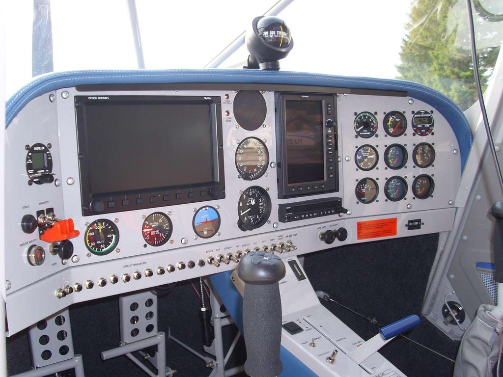
60 Assembly identification: Bar code: Table of parts for the assembly of the instruments Airspeed indicator Part s identification: AS 51 Bar code: Airspeed indicator model AS51, optional in km/h or knots. Transponder Part s identification: TRT 800 Bar code: Technical data Dimensions: FI 57mm, 1600mm depth Weight: ca. 700g Power consumption idle: ca. 200mmA Min output power: 125W Voltage: 10, 5-16V or 22-30V Transponder Mode A/C and S, extended squitter capability. Integrated alticoder up to ft, 100ft, Increments (TRT800H up to ft) Simple operation on 4-line display: - Active- and standby-squawk - Modes: STBY, A, A/C, S - Flags and Flight Level Solid state. Aircraft Adapter for ICAO 24-bit address and Flight ID remain in aircraft. Altimeter Part s identification: A7 Bar code: Altimeter model A7 model with more pointers Range: ft Small barometric window mb Diameter 3 1/8 80mm Bank and yaw indicator Part s identification: SB Bar code:


61 FUSELAGE Assembly identification: Bar code: Table of parts for the assembly of the instruments Vertical speed indicator Part s identification: VS 10 Bar code: Vertical speed indicator model VS10 Range ft Diameter 3 1/8 80mm Engine RPM Part s identification: IM 105 Bar code: Oil pressure indicator Part s identification: RA Bar code: VHF Radio Part s identification: ATR833 / KRT-2 Bar code: / NOTE Optional ATR833 KRT-2 60


62 Assembly identification: Bar code: Table of parts for the assembly of the instruments Oil temperature indicator Part s identification: 01054RA Bar code: Outside temperature indicator Part s identification: Bar code: NOTE Optional CHT Liquid temperature Part s identification: 01060RA Bar code: Voltmeter Part s identification: 01056RA Bar code:


63 FUSELAGE Assembly identification: Bar code: Table of parts for the assembly of the instruments Magnetic compass Part s identification: Bar code: GPS Part s identification: Garmin 695 Bar code: NOTE Optional Hour meter Part s identification: 00296R Bar code: Trim position indicator Part s identification: RP3 Bar code:


64 Assembly identification: Bar code: Table of parts for the assembly of the instruments Flaps position indicator Part s identification: RP3 Bar code: Flaps actuator switch Part s identification: Bar code: Choke switch Part s identification: 00603B Bar code: Magnets switches Part s identification: 00046CV Bar code:


65 FUSELAGE Assembly identification: Bar code: Table of parts for the assembly of the instruments Master switch Part s identification: 00032USA Bar code: Start switch Part s identification: 00047D Bar code: Breakers 5A 7A 10A 15A 30A Part s identification: / / / / Bar code: / / / / (No image) 64
66 (Intentionally left blank) 65
67 66
68 FIRST FRAMEWORK Assembly identification: TR
69 FUSELAGE Table of parts for the assembly of the first framework Assembly identification: TR Bar code: Position: 1 Upper carrier Part s identification: TR Bar code: Position: 2 Left side carrier Part s identification: TR L Bar code: Position: 3 Right side carrier Part s identification: TR R Bar code: Position: 4 Left lower cage carrier Part s identification: TR L Bar code: Position: 5 Right lower cage carrier Part s identification: TR R Bar code:
70 Table of parts for the assembly of the first framework Assembly identification: TR Bar code: Position: 6 Left sheet metal for the connection of the upper and side carrier Part s identification: TR L Bar code: Position: 7 Right sheet metal for the connection of the upper and side carrier Part s identification: TR R Bar code: Position: 8 Angular connection between the upper and the side carrier Part s identification: TR Bar code: Position: 9 Bigger left sheet metal for the connection of the first framework and upper front stringer Part s identification: TR L Bar code: Position: 10 Bigger right sheet metal for the connection of the first framework and upper front stringer Part s identification: TR R Bar code:
71 FUSELAGE Table of parts for the assembly of the first framework Assembly identification: TR Bar code: Position: 11 Smaller left sheet metal for the connection of the first framework and upper front stringer Part s identification: TR L Bar code: Position: 12 Smaller right sheet metal for the connection of the first framework and upper front stringer Part s identification: TR R Bar code: Position: 13 Left profile for the connection of the belt carrier Part s identification: TR L Bar code: Position: 14 Right profile for the connection of the belt carrier Part s identification: TR R Bar code: Position: 15 Upper reinforcement of the first framework Part s identification: TR Bar code: Table: Bolts, screw nuts, washers and rivets used for the assembly of the first framework Position Name Description Rivet 5/ Rivet 5/ Rivet F5/ AN3-5A Bolt 3/16-5A 20 AN Washer 3/16 21 AN Screw nut 3/16 70
72 (Intentionally left blank) 71
73 SECOND FRAMEWORK 72 Assembly identification: TR
74 FUSELAGE Table of parts for the assembly of the second framework Assembly identification: TR Bar code: Position: 1 Main profile of the second framework Part s identification: TR Bar code: Position: 2 Longitudinal reinforcement of the second framework Part s identification: TR Bar code: Position: 3 Teflon bearing of the torsion lever of the controls Part s identification: TR Bar code: Table: Bolts, screw nuts, washers and rivets used for the assembly of the second framework Position Name Description Rivet 5/ Rivet 5/
75 (Intentionally left blank) 74
76 THIRD FRAMEWORK 75 Assembly identification: TR
77 FUSELAGE Table of parts for the assembly of the third framework Assembly identification: TR Bar code: Position: 1 Left part of the third framework Part s identification: TR Bar code: Position: 2 Right part of the third framework Part s identification: TR Bar code: Position: 3 Reinforcement of the third framework Part s identification: TR Bar code: Position: 4 Teflon rope conductor Part s identification: TR Bar code: Table: Bolts, screw nuts, washers and rivets used for the assembly of the third framework Position Name Description Rivet 1/
78 (Intentionally left blank) 77
79 FOURTH FRAMEWORK 78 Assembly identification: TR
80 FUSELAGE Table of parts for the assembly of the fourth framework Assembly identification: TR Bar code: Position: 1 Upper part of the fourth framework Part s identification: TR Bar code: Position: 2 Lower part of the fourth framework Part s identification: TR Bar code: Position: 3 Reinforcement of the framework Part s identification: TR Bar code: Position: 4 Teflon rope conductor Part s identification: TR Bar code: Position: 5 Rubber inlet for the cables Part s identification: MS Bar code: NOTE Standard part Table: Bolts, screw nuts, washers and rivets used for the assembly of the fourth framework Position Name Description Rivet 1/
81 (Intentionally left blank) 80
82 FIFTH FRAMEWORK Assembly identification: TR
83 FUSELAGE Table of parts for the assembly of the fifth framework Assembly identification: TR Bar code: Position: 1 Upper part of the fifth framework Part s identification: TR Bar code: Position: 2 Lower part of the fifth framework Part s identification: TR Bar code: Position: 3 Reinforcement of the framework Part s identification: TR Bar code: Position: 4 Teflon rope conductor Part s identification: TR Bar code: Position: 5 Rubber inlet for the cables Part s identification: MS Bar code: NOTE Standard part Table: Bolts, screw nuts, washers and rivets used for the assembly of the fifth framework Position Name Description Rivet 1/
84 (Intentionally left blank) 83
85 SIXTH FRAMEWORK Assembly identification: TR
86 FUSELAGE Table of parts for the assembly of the sixth framework Assembly identification: TR Bar code: Position: 1 Upper part of the sixth framework Part s identification: TR Bar code: Position: 2 Lower part of the sixth framework Part s identification: TR Bar code: Position: 3 Reinforcement of the sixth framework Part s identification: TR Bar code: Position: 4 Reinforcement of the framework Part s identification: TR Bar code: Position: 5 Teflon conductor for the rope Part s identification: TR Bar code:
87 Table of parts for the assembly of the sixth framework Assembly identification: TR Bar code: Position: 6 Rubber inlet of the cables Part s identification: MS Bar code: NOTE Standard part Table: Bolts, screw nuts, washers and rivets used for the assembly of the sixth framework Position Name Description Rivet 1/
88 FUSELAGE (Intentionally left blank) 87
89 BASIC STRUCTURE OF THE FUSELAGE 88 Assembly identification: TR F
90 FUSELAGE Table of parts for the assembly of the basic structure of the fuselage Assembly identification: TR F Bar code: Position: 1 Front lower skin Part s identification: TR Bar code: Position: 2 Second framework Part s identification: TR Bar code: NOTE Complete assembly as the subassembly of the basic structure of the fuselage Position: 3 Third framework Part s identification: TR Bar code: NOTE Complete assembly as the subassembly of the basic structure of the fuselage Position: 4 Fourth framework Part s identification: TR Bar code: NOTE Complete assembly as the subassembly of the basic structure of the fuselage Position: 5 Fifth framework Part s identification: TR Bar code: NOTE Complete assembly as the subassembly of the basic structure of the fuselage 89
91 Table of parts for the assembly of the basic structure of the fuselage Assembly identification: TR F Bar code: Position: 6 Sixth framework Part s identification: TR Bar code: NOTE Complete assembly as the subassembly of the basic structure of the fuselage Position: 7 Seventh framework Part s identification: TR Bar code: Position: 8 Eight framework Part s identification: TR Bar code: Position: 9 Ninth framework Part s identification: TR Bar code: Position: 10 Rear connection of the middle stringers Part s identification: TR F Bar code:
92 FUSELAGE Table of parts for the assembly of the basic structure of the fuselage Assembly identification: TR F Bar code: Position: 11 Left slope stiffening of the eighth and ninth framework Part s identification: TR L Bar code: Position: 12 Right slope stiffening of the eighth and ninth framework Part s identification: TR R Bar code: Position: 13 Rear guide of the rope Part s identification: TR Bar code: Position: 14 First framework Part s identification: TR Bar code: NOTE Complete assembly as the subassembly of the basic structure of the fuselage Position: 15 Lower left stringer Part s identification: TR L Bar code:
93 Table of parts for the assembly of the basic structure of the fuselage Assembly identification: TR F Bar code: Position: 16 Right lower stringer Part s identification: TR R Bar code: Position: 17 Left middle stringer Part s identification: 5313-TR L Bar code: Position: 18 Right middle stringer Part s identification: TR R Bar code: Position: 19 Left side skin Part s identification: TR L Bar code: Position: 20 Right side skin Part s identification: TR R Bar code:
94 FUSELAGE Table of parts for the assembly of the basic structure of the fuselage Assembly identification: TR F Bar code: Position: 21 Carrier on the outer lower left stringer Part s identification: TR L Bar code: Position: 22 Carrier on the outer lower right stringer Part s identification: TR R Bar code: Position: 23 Left lower side reinforcement between the first and the fourth framework Part s identification: TR L Bar code: Position: 24 Right lower side reinforcement between the first and the fourth framework Part s identification: TR R Bar code: Position: 25 Teflon support of the rear control bridge Part s identification: TR Bar code:
95 Table of parts for the assembly of the basic structure of the fuselage Assembly identification: TR F Bar code: Position: 26 Rubber inlet for the cables Part s identification: MS Bar code: Position: 27 Left sheet metal for the connection of the middle stringer and first framework Part s identification: TR L Bar code: Position: 28 Right sheet metal for the connection of the middle stringer and the first framework Part s identification: TR R Bar code: Position: 31 Washer for the connection of the Teflon support of the rear control bridge Part s identification: TR Bar code: Position: 32 Left bottom stringer Part s identification: TR L Bar code:
96 FUSELAGE Table of parts for the assembly of the basic structure of the fuselage Assembly identification: TR F Bar code: Position: 33 Right bottom stringer Part s identification: TR R Bar code: Position: 34 Lower middle skin Part s identification: TR Bar code: Position: 35 Lower rear skin Part s identification: TR Bar code: Position: 36 Lower tail skin Part s identification: TR Bar code: Position: 37 Left carrier of the Teflon bearing of the rear control bridge Part s identification: TR L Bar code:
97 Table of parts for the assembly of the basic structure of the fuselage Assembly identification: TR F Bar code: Position: 38 Right carrier of the Teflon bearing of the rear control bridge Part s identification: TR R Bar code: Position: 39 Left bearing of the rear control bridge Part s identification: TR L Bar code: Position: 40 Right bearing of the rear control bridge Part s identification: TR R Bar code: Table: Bolts, screw nuts, washers and rivets used for the assembly of the basic structure of the fuselage Position Name Description Rivet 1/ Rivet 5/ Rivet 5/ AN 3/16 Bolt 3/
98 FUSELAGE (Intentionally left blank) 97
99 INSTALLATION OF THE FUSELAGE STRUCTURE 98 Assembly identification: TR F

100 FUSELAGE Table of parts for the assembly of the installation of the fuselage structure Assembly identification: TR F Bar code: Position: 1 Basic structure of the fuselage Part s identification: TR F Bar code: NOTE Complete assembly as the subassembly of the installation of the fuselage structure Position: 2 Upper rear skin Part s identification: TR Bar code: Position: 3 Upper front skin Part s identification: TR Bar code: Position: 4 Outer left L profile Part s identification: TR L Bar code: Position: 5 Outer right L profile Part s identification: TR R Bar code:
101 Table of parts for the assembly of the installation of the fuselage structure Assembly identification: TR F Bar code: Position: 6 Inner left L profile Part s identification: TR L Bar code: Position: 7 Inner right L profile Part s identification: TR R Bar code: Position: 8 Left U profile connection of the outer and inner L profile Part s identification: TR L Bar code: Position: 9 Right U profile connection of the outer and inner L profile Part s identification: TR R Bar code: Position: 10 Side sheet metal for the connection of the front and rear upper stringer Part s identification: TR Bar code:
102 FUSELAGE Table of parts for the assembly of the installation of the fuselage structure Assembly identification: TR F Bar code: Position: 11 Reinforcement at the parachute opening Part s identification: TR Bar code: Position: 12 Left sheet metal for the connection of the front and rear stringer Part s identification: TR L Bar code: Position: 13 Right sheet metal for the connection of the front and rear stringer Part s identification: TR R Bar code: Position: 14 Left profile for the connection of the front upper stringer and fourth framework Part s identification: TR L Bar code: Position: 15 Right profile for the connection of the front upper stringer and fourth framework Part s identification: TR R Bar code:
103 Table of parts for the assembly of the installation of the fuselage structure Assembly identification: TR F Bar code: Position: 18 Left upper carrier of the cage Part s identification: TR L Bar code: Position: 19 Right upper carrier of the cage Part s identification: TR R Bar code: Position: 20 Radio antenna carrier Part s identification: TR F Bar code: Position: 22 Left upper stringer Part s identification: TR L Bar code: Position: 23 Right upper stringer Part s identification: TR R Bar code:
104 FUSELAGE Table of parts for the assembly of the installation of the fuselage structure Assembly identification: TR F Bar code: Position: 24 Upper left carrier of the belt Part s identification: TR L Bar code: Upper right carrier of the belt Part s identification: TR R Bar code: Position: 25 Table: Bolts, screw nuts, washers and rivets used for the installation of the fuselage structure Position Name Description Rivet 1/ Rivet 5/ Rivet F1/
105 (Intentionally left blank) 104
106 ASSEMBLY OF THE FUSELAGE STRUCTURE 105 Assembly identification: TR TF

107 FUSELAGE Table of parts for the assembly of the fuselage structure Assembly identification: TR TF Bar code: Position: 1 Installation of the fuselage structure Part s identification: TR F Bar code: NOTE The complete assembly as the subassembly of the asembly of the fuselage structure Position: 2 Basic cockpit Part s identification: KB Bar code: NOTE The complete assembly as the subassembly of the asembly of the fuselage structure Position: 3 Outer Al tube of the cockpit cage Part s identification: KB Bar code: Position: 4 Inner Al tube of the cockpit cage Part s identification: KB Bar code: Position: 5 Left carrier of the leg of the landing gear Part s identification: KB Bar code:
108 Table of parts for the assembly of the fuselage structure Assembly identification: TR TF Bar code: Position: 6 Right carrier of the leg of the landing gear Part s identification: KB Bar code: Position: 7 Left profile for the connection of the side sheet metal and the landing gear carrier Part s identification: KB L Bar code: Position: 8 Right profile for the connection of the side sheet metal and the landing gear carrier Part s identification: KB R Bar code: Position: 13 Assembly of the main carrier of the landing gear Part s identification: TR L Bar code: NOTE Complete assembly as the subassembly of the assembly of the fuselage structure Lower cover of the main carrier of the landing gear Part s identification: KB Bar code: Position:
109 FUSELAGE Table of parts for the assembly of the fuselage structure Assembly identification: TR TF Bar code: Position: 15 Left Reinforcement on the revision opening Part s identification: TR L Bar code: Position: 16 Right reinforcement on the revision opening Part s identification: TR R Bar code: Position: 17 Rear left reinforcement of the side sheet metal Part s identification: KB L Bar code: Position: 18 Rear right reinforcement of the side sheet metal Part s identification: KB R Bar code: Position: 19 Left side controls carrier Part s identification: KB L Bar code:
110 Table of parts for the assembly of the fuselage structure Assembly identification: TR TF Bar code: Position: 20 Right side controls carrier Part s identification: KB R Bar code: Position: 21 Left auxiliary controls carrier Part s identification: KB L Bar code: Position: 22 Right auxiliary controls carrier Part s identification: KB R Bar code: Position: 23 Cockpit carrier Part s identification: TR F Bar code: NOTE Complete assembly as the subassembly of the assembly of the fuselage structure Position: 24 Central seat carrier Part s identification: KB Bar code:
111 FUSELAGE Table of parts for the assembly of the fuselage structure Assembly identification: TR TF Bar code: Position: 25 Left side stiffening of the controls carrier Part s identification: KB L Bar code: Position: 26 Right side stiffening of the control carrier Part s identification: KB R Bar code: Position: 27 Front slider of the controls Part s identification: KB Bar code: Position: 28 Hat of the front bridge Part s identification: KO Bar code: Position: 29 Front Control Bridge Part s identification: KO Bar code:
112 Table of parts for the assembly of the fuselage structure Assembly identification: TR TF Bar code: Position: 30 Torsion axle Part s identification: KO Bar code: Position: 31 Left profile for the connection of the seat carrier on the landing gear carrier Part s identification: KB L Bar code: Position: 32 Right profile for the connection of the seat carrier on the landing gear carrier Part s identification: KB R Bar code: Position: 48 Left inner carrier of on the lower stringer Part s identification: TR L Bar code: Position: 49 Right inner carrier on the lower stringer Part s identification: TR R Bar code:
113 FUSELAGE Table of parts for the assembly of the fuselage structure Assembly identification: TR TF Bar code: Position: 50 Cover of the front cockpit Part s identification: KB T Bar code: Position: 51 Front connection of the cockpit cage Part s identification: KB Bar code: Position: 52 Longitudinal reinforcement of the cover of the cockpit and connection firewall-instrument panel Part s identification: KB T Bar code: Position: 57 Instrument panel Part s identification: KB T Bar code: NOTE Complete assembly as the subassembly of the assembly of the fuselage structure Position: 58 Cockpit cage Part s identification: KB Bar code:
114 Table of parts for the assembly of the fuselage structure Assembly identification: TR TF Bar code: Position: 59 Left angular profile for the connection of the horizontal strut on the lateral sheet metal and first framework Part s identification: KB L Bar code: Position: 60 Right angular profile for the connection of the horizontal strut on the lateral sheet metal and first framework Part s identification: KB R Bar code: Position: 62 Cover on the lateral sheet metal Part s identification: TR Bar code: Position: 64 Lateral carrier of the belt Part s identification: TR Bar code: Table: Bolts, screw nuts, washers and rivets used for the assembly the fuselage structure Position Name Description 33 K Screw nut Rivet 5/ Rivet 5/ AN4-10A Bolt 1/ AN4-7A Bolt 1/ AN Washer 1/4 39 AN A Screw nut 1/4 40 AN3-5A Bolt 3/ AN Washer 3/16 44 AN A Srew nut 3/ Rivet F1/ Rivet 1/ Rivet F1/ AN4-5A Bolt 1/4-5A 54 AN5-6A Bolt 5/16-6A 55 AN Washer 5/16 56 AN A Screw nut 5/16 61 AN470AD5-9 Rivet S5/32-9 AN R8 Bolt 832R8 113
115 FUSELAGE (Intentionally left blank) 114
116 FUSELAGE WITH THE INNER STRUCTURE Assembly identification: TR TF 115
117 FUSELAGE Table of parts for the assembly of the fuselage with the inner structure Assembly identification: TR TF Bar code: Position: 2 Side reinforcement between first and fourth framework left Part s identification: TR L Bar code: Position: 3 Side reinforcement between first and fourth framework right Part s identification: TR R Bar code: Position: 4 Profile between the connection of the b.c. and rear cabin wall and b.c. carrier - right Part s identification: TR F Bar code: Position: 5 Profile between the connection of the b.c. and rear cabin wall and b.c. carrier - left Part s identification: TR F Bar code: Position: 6 Profile between the connection of the b.c. and rear cabin wall and b.c. carrier - middle Part s identification: TR F Bar code:
118 Table of parts for the assembly of the fuselage with the inner structure Assembly identification: TR TF Bar code: Position: 7 Profile for the con between rear and mid. baggage compartment carrier - right Part s identification: TR F Bar code: Position: 8 Profile for the connection between rear and middle baggage compartment carrier - middle Part s identification: TR F Bar code: Position: 9 Profile for the connection between rear and middle baggage compartment carrier - left Part s identification: TR F Bar code: Position: 10 Front carrier of the baggage compartment Part s identification: TR Bar code: Position: 11 Middle carrier of the baggage compartment Part s identification: TR Bar code:
119 FUSELAGE Table of parts for the assembly of the fuselage with the inner structure Assembly identification: TR TF Bar code: Position: 12 Rear carrier of the baggage compartment Part s identification: TR Bar code: Position: 13 The connection between the baggage compartment and rear cabin wall Part s identification: TR Bar code: Position: 14 Carrier of the cover of the rocket engine left Part s identification: TR L Bar code: Position: 15 Carrier of the cover of the rocket engine right Part s identification: TR R Bar code: Position: 16 Cover of the rocket engine Part s identification: TR Bar code: Table: Bolts, screw nuts, washers and rivets used for the assembly of the fuselage with the inner structure Position Name Description Rivet N1/ Rivet 1/ DIN 7337 Rivet F1/
120 (Intentionally left blank) 119
121 REAR CONTROL BRIDGE IN THE FUSELAGE 120 Assembly identification: TR TF
122 FUSELAGE Table of parts for the assembly of the rear control bridge in the fuselage Assembly identification: TR TF Bar code: Position: 2 Lower lever of the flap control Part s identification: KO Bar code: Position: 3 Rear Control Bridge Part s identification: KO Bar code: Position: 4 Middle carrier of the rear control bridge - left Part s identification: TR L Bar code: Position: 5 Middle carrier of the rear control bridge - right Part s identification: TR R Bar code: Position: 6 Longitudinal reinforcement of the flap engine carrier - left Part s identification: TR L Bar code:
123 Table of parts for the assembly of the rear control bridge in the fuselage Assembly identification: TR TF Bar code: Position: 7 Longitudinal reinforcement of the flap engine carrier - right Part s identification: TR R Bar code: Position: 8 Carrier of the flap engine - right Part s identification: TR Bar code: Position: 9 Carrier of the flap engine - left Part s identification: TR Bar code: Position: 10 Side connection of the right carrier of the flap engine Part s identification: TR Bar code: Position: 11 Carrier of the flap engine lever - left Part s identification: TR L Bar code:
124 FUSELAGE Table of parts for the assembly of the rear control bridge in the fuselage Assembly identification: TR TF Bar code: Position: 12 Carrier of the flap engine lever - right Part s identification: TR R Bar code: Position: 13 Flap engine Part s identification: AO-01M C100F00CC Bar code: NOTE Standard part Position: 14 V - lever Part s identification: KO Bar code: Position: 15 Carrier Part s identification: KO Bar code: Position: 16 Carrier Part s identification: KO Bar code:
125 Table of parts for the assembly of the rear control bridge in the fuselage Assembly identification: TR TF Bar code: Position: 17 Carrier Part s identification: KO Bar code: Position: 18 Angular sheet metal for the connection of the second framework left Part s identification: TR L Bar code: Position: 19 Angular sheet metal for the connection of the second framework right Part s identification: TR R Bar code: Position: 20 Reinforcement between the second framework and the flap engine lever carrier Part s identification: TR Bar code: Position: 21 Reinforcement between the stringer and the second framework Part s identification: TR Bar code:
126 FUSELAGE Table of parts for the assembly of the rear control bridge in the fuselage Assembly identification: TR TF Bar code: Position: 39 Al tube Part s identification: Al tube Bar code: Position: 40 Reinforcement of the right carrier of the lever of the flap engine Part s identification: TR Bar code: Table: Bolts, screw nuts, washers and rivets used for the assembly of the rear control bridge in the fuselage Position Name Description Rivet 1/ Rivet 5/ Rivet 5/ AN3-5A Bolt 3/ AN3-14A Bolt 3/ AN3-12A Bolt 3/ AN4-17A Bolt 1/ AN Washer 3/16 30 AN A Screw nut 3/16 31 AN Washer 1/4 32 AN A Screw nut 1/4 33 DIN 912 ISO 4762 Bolt M6x40 INBUS 34 DIN 912 ISO 4762 Bolt M8x70 INBUS 35 DIN 125 Washer M6 36 DIN 125 Washer M8 37 DIN 985 ISO 7040 Screw nut M6 38 DIN 985 ISO 7040 Screw nut M8 125
127 (Intentionally left blank) 126
128 COCKPIT WALLS Assembly identification: TR TF 127

129 FUSELAGE Table of parts for the assembly of the cockpit walls Assembly identification: TR TF Bar code: Position: 1 Rear Control Bridge in the fuselage Part s identification: TR TF Bar code: NOTE Complete assembly as the subasembly of the cockpit walls Position: 2 Rear lower wall of the cabin Part s identification: TR F Bar code: Position: 3 Reinforcement of the rear lower wall of the cabin left Part s identification: TR L Bar code: Position: 4 Reinforcement of the rear lower wall of the cabin right Part s identification: TR R Bar code: Position: 5 Floor of the rear part of the cabin Part s identification: TR F Bar code:
130 Table of parts for the assembly of the cockpit walls Assembly identification: TR TF Bar code: Position: 6 Rear cabin wall Part s identification: TR F Bar code: Position: 7 Sheet metal on the top of the rear lower wall of the cabin Part s identification: TR Bar code: Position: 8 Cover between rear lower wall of the cabin and first framework left Part s identification: TR L Bar code: Position: 9 Cover between rear lower wall of the cabin and first framework right Part s identification: TR R Bar code: Table: Bolts, screw nuts, washers and rivets used for the assembly of the cockpit walls Position Name Description Rivet 5/ Rivet 1/
131 FUSELAGE (Intentionally left blank) 130
132 LEVERS ON THE REAR CONTROL BRIDGE 131 Assembly identification: TR TF

133 FUSELAGE Table of parts for the assembly of the levers on the rear control bridge Assembly identification: TR TF Bar code: Position: 1 Cockpit walls Part s identification: TR TF Bar code: NOTE Complete assembly as the subassembly of the levers on the rear control bridge Position: 2 Seesaw Part s identification: KO Bar code: Position: 3 Vertical flap control Part s identification: KO Bar code: Position: 4 Vertical lever of the aileron control Part s identification: KO Bar code: Position: 5 Teflon of the rear control bridge Part s identification: TR Bar code:
134 Table of parts for the assembly of the levers on the rear control bridge Assembly identification: TR TF Bar code: Position: 6 Washer of the rear control bridge Part s identification: TR Bar code: Position: 8 Small vertical lever Part s identification: KO Bar code: Position: 13 Al tube Part s identification: Al tube Bar code: Position: 14 Spherical bearing Part s identification: MW-5 Aurora Bar code: Table: Bolts, screw nuts, washers and rivets used assembly of the for levers on the rear control bridge Position Name Description 7 AN Cutter 1/ AN 5-13A Bolt 5/ AN 5-11A Bolt 5/ AN Washer 5/16 12 AN A Screw nut 5/16 15 AN315-5R Screw nut 5/16 Full hex 133
135 FUSELAGE (Intentionally left blank) 134
136 LEFT DOOR 135 Assembly identification: KB L
137 FUSELAGE Table of parts for the assembly of the left door Assembly identification: KB L Bar code: Position: 1 Upper part of the frame Part s identification: KB Bar code: Position: 2 Rear part of the frame Part s identification: KB Bar code: Position: 3 Front part of the frame Part s identification: KB Bar code: Position: 4 Lower part of the frame Part s identification: KB Bar code: Position: 7 Middle horizontal part of the frame left Part s identification: KB L Bar code:
138 Table of parts for the assembly of the left door Assembly identification: KB L Bar code: Position: 8 Middle vertical part of the frame left Part s identification: KB L Bar code: Position: 9 Reinforcement 8 left Part s identification: KB L Bar code: Position: 10 Reinforcement 9 left Part s identification: KB L Bar code: Position: 11 Reinforcement 10 left Part s identification: KB L Bar code: Position: 12 Reinforcement 11 left Part s identification: KB L Bar code:
139 FUSELAGE Table of parts for the assembly of the left door Assembly identification: KB L Bar code: Position: 13 Reinforcement 12 left Part s identification: KB L Bar code: Position: 14 Reinforcement 13 left Part s identification: KB L Bar code: Position: 15 Reinforcement 14 left Part s identification: KB L Bar code: Position: 16 Reinforcement 15 left Part s identification: KB L Bar code: Position: 17 Holder of the door in the open position Part s identification: KB Bar code:
140 Table of parts for the assembly of the left door Assembly identification: KB L Bar code: Position: 18 Additional sheet metal reinforcement Part s identification: KB Bar code: Position: 19 Front lower sheet metal left Part s identification: KB PL Bar code: Position: 20 Rear lower sheet metal left Part s identification: KB ZL Bar code: Position: 21 Upper front sheet metal left Part s identification: KB L Bar code: Position: 22 Upper rear sheet metal left Part s identification: KB L Bar code:
141 FUSELAGE Table of parts for the assembly of the left door Assembly identification: KB L Bar code: Position: 23 Connection 03 and 04 Part s identification: KB Bar code: Position: 24 Pane of the door Part s identification: KB Bar code: Position: 25 Front hinge Part s identification: KB Bar code: Position: 26 Rear hinge Part s identification: KB Bar code: Position: 27 Lock for the door Part s identification: Lock for the door with the key Bar code:
142 Table of parts for the assembly of the left door Assembly identification: KB L Bar code: Position: 28 Rubber hose Part s identification: Rubber hose F50x15mm Bar code: Position: 33 Release lever Part s identification: KB Bar code: Position: 34 Carrier of the doors at the first framework left Part s identification: KB L Bar code: Table: Bolts, screw nuts, washers and rivets used for the assembly of the left door Position Name Description 29 AN470AD3-3 Rivet S3/ AN470AD3-4 Rivet S3/ Rivet 1/ DIN 7337 Rivet N1/
143 FUSELAGE (Intentionally left blank) 142
144 RIGHT DOOR Assembly identification: KB R 143
145 FUSELAGE Table of parts for the assembly of the right door Assembly identification: KB R Bar code: Position: 1 Upper part of the frame Part s identification: KB Bar code: Position: 2 Rear part of the frame Part s identification: KB Bar code: Position: 3 Front part of the frame Part s identification: KB Bar code: Position: 4 Lower part of the frame Part s identification: KB Bar code: Position: 7 Middle horizontal part of the frame right Part s identification: KB R Bar code:
146 Table of parts for the assembly of the right door Assembly identification: KB R Bar code: Position: 8 Middle vertical part of the frame right Part s identification: KB R Bar code: Position: 9 Reinforcement 8 right Part s identification: KB R Bar code: Position: 10 Reinforcement 9 right Part s identification: KB R Bar code: Position: 11 Reinforcement 10 right Part s identification: KB R Bar code: Position: 12 Reinforcement 11 right Part s identification: KB R Bar code:
147 FUSELAGE Table of parts for the assembly of the right door Assembly identification: KB R Bar code: Position: 13 Reinforcement 12 right Part s identification: KB R Bar code: Position: 14 Reinforcement 13 right Part s identification: KB R Bar code: Position: 15 Reinforcement 14 right Part s identification: KB R Bar code: Position: 16 Reinforcement 15 right Part s identification: KB R Bar code: Position: 17 Holder of the door in the open position Part s identification: KB Bar code:
148 Table of parts for the assembly of the right door Assembly identification: KB R Bar code: Position: 18 Additional sheet metal reinforcement Part s identification: KB Bar code: Position: 19 Front lower sheet metal right Part s identification: KB PR Bar code: Position: 20 Rear lower sheet metal right Part s identification: KB ZR Bar code: Position: 21 Upper front sheet metal right Part s identification: KB R Bar code: Position: 22 Upper rear sheet metal right Part s identification: KB R Bar code:
149 FUSELAGE Table of parts for the assembly of the right door Assembly identification: KB R Bar code: Position: 23 Connection 03 and 04 Part s identification: KB Bar code: Position: 24 Frame of the door Part s identification: KB Bar code: Position: 25 Front hinge Part s identification: KB Bar code: Position: 26 Rear hinge Part s identification: KB Bar code: Position: 27 Lock for the door Part s identification: Lock for the door without key Bar code:
150 Table of parts for the assembly of the right door Assembly identification: KB R Bar code: Position: 28 Rubber hose Part s identification: Rubber hose F50x15mm Bar code: Position: 33 Release lever Part s identification: KB Bar code: Position: 34 Carrier of the doors at the first framework left Part s identification: KB L Bar code: Table: Bolts, screw nuts, washers and rivets used for the assembly of the right door Position Name Description 29 AN470AD3-3 Rivet S3/ AN470AD3-4 Rivet S3/ Rivet 1/ DIN 7337 Rivet N1/
151 FUSELAGE (Intentionally left blank) 150
152 ASSEMBLY OF THE COCKPIT WINDOWS 151 Assembly identification: PR
153 FUSELAGE Table of parts for the assembly of the cockpit windows Assembly identification: PR Bar code: Position: 2 Windshield Part s identification: PR Bar code: Position: 3 Left window Part s identification: PR L Bar code: Position: 4 Right window Part s identification: PR R Bar code: Position: 5 Window at the opening for the parachute Part s identification: PR Bar code: Table: Bolts, screw nuts, washers and rivets used for the assembly of the cockpit windows Position Name Description 6 DIN 7337 Rivet N3/
154 (Intentionally left blank) 153
155 SILA 450C SPARE PARTS CATALOG INSTALLATION OF THE ENGINE Assembly identification: 154
156 FUSELAGE Assembly identification: Bar code: Table of parts for the assembly of the engine Position: 1 Angular sheet metal for the connection of the firewall and cowling upper - left Part s identification: KB L Bar code: Position: 2 Angular sheet metal for the connection of the firewall and cowling upper - right Part s identification: KB R Bar code: Position: 3 Angular sheet metal for the connection of the firewall and cowling lower left Part s identification: KB L Bar code: Position: 4 Angular sheet metal for the connection of the firewall and cowling lower right Part s identification: KB R Bar code: Position: 5 Engine mount Part s identification: NM Bar code:

157 Assembly identification: Bar code: Table of parts for the assembly of the engine Position: 6 Silent block Part s identification: Bar code: Position: 7 Engine Part s identification: ROTAX 912 ULS 2 Bar code: Position: 8 Lower part of the cowling Part s identification: PL.MP Bar code: Position: 9 Upper part of the cowling Part s identification: PL.MP Bar code: Position: 10 Covers of the cowling Part s identification: Bar code: PL.MP.02.07L, R 156
158 FUSELAGE Assembly identification: / Bar code: Table of parts for the assembly of the engine Position: 11 Rosette Part s identification: Rosette Bar code: Position: 12 Rosette Part s identification: Rosette Bar code: Position: 13 Connector for the Rosette Part s identification: Rosette Bar code: Position: 14 Battery Part s identification: Bar code: Position: 15 Exhaust expansion pot Part s identification: IS Bar code:
159 Assembly identification: / Bar code: Table of parts for the assembly of the engine Position: 16 Longer exhaust manifold right Part s identification: IS R Bar code: Position: 17 Longer exhaust manifold left Part s identification: IS L Bar code: Position: 18 Shorter exhaust manifold left Part s identification: IS L Bar code: Position: 19 Shorter exhaust manifold right Part s identification: IS R Bar code:
160 FUSELAGE (Intentionally left blank) 159

161 INSTALLATION OF THE PROPELLER Type: PROPULSE AES 170 Three blades, on ground adjustable propeller. The propeller blades are manufactured with a composite shell, formed from a special, new generation fabric. This design creates an excellent sandwich construction. The rotational and centrifugal forces are transferred to the propeller hub by means of significant structural element, i.e. composite shaped tube, which is inserted into shank, blade root and so into the blade body itself. Part s identification: AES 170 Bar code: Type: WOODCOMP SR 3000/3 SR 3000 is a three bladed electrically operated in flight adjustable aircraft propeller of mixed structure. The angle of blade setting is adjusted by a servomotor controlled from the cockpit and it can be adjusted smoothly in the range from the minimum (fine) angle intended for take-off up to the maximum (coarse) angle. The propeller can be used in both tractor and pusher applications. The propeller can operate with either of manual control or with automatic control as a constant speed propeller. Part s identification: SR 3000/3 Bar code: Type: WOODCOMP SR 200 Propeller diemeter: mm Application: For different engine types max 100HP ROTAX, SUBARU, BMW, VERNER, HKS, NISSAN, etc. Constructional design: 1. WOOD-CARBON + LIGNOSTONE (BLACK) BLADES WITH PLASTIC LEADING EDGE For propeller blades with wooden core and carbon fibre surface, the leading edges of the blades are cast from highly resistant plastic material, that serves as protection against impacting sand, small stones, water and other effects, which may damage propeller blades. These blades are available for propeller diameter 1600mm mm. 2. WOOD-COMPOSITE + LIGNOSTONE (WHITE) BLADES WITH PLASTIC LEADING EDGE. For propeller blades with wooden core and glass-laminated surface in white or black colour, the leading edges of the blades are cast from highly resistant plastic material, which serves as protection against impact of sand, small stones, water and other effects, which damage propeller blades. These blades are available for propeller diameter 1600mm mm. 3. WOODEN BLADES WITH COMPOSITE LEADING EDGE.Wooden propeller blades, that are equipped with leading edges made of highly resistant composite material, serving as protection against impact of sand, small stones, water and other effects, which damage propeller blades. The blade surface is protected with several spray coatings of very high quality and highly resistant polyurethane paint. The colour versions are TRANSPARENT or WHITE. These blades are available for blade diameters of 1500mm, and 1600mm mm Part s identification: SR 200 Bar code:
162 FUSELAGE (Intentionally left blank) 161
163 162
164 REAR SPAR OF THE HORIZONTAL STABILIZER 163 Assembly identification: sh
165 EMPENNAGE Table of parts for the assembly of the rear spar of the horizontal stabilizer Assembly identification: SH Bar code: Position: 1 Rear spar Part s identification: SH Bar code: Position: 2 Inset of the rear spar Part s identification: SH Bar code: Table: Bolts, screw nuts, washers and rivets used for the assembly of the rear spar of the horizontal stabilizer Position Name Description Rivet 1/
166 (Intentionally left blank) 165
167 STRUCTURE OF THE HORIZONTAL STABILIZER 166 Assembly identification: SH
168 EMPENNAGE Table of parts for the assembly of the structure of the horizontal stabilizer Assembly identification: SH Bar code: Position: 1 Rear spar of the horizontal stabilizer Part s identification: SH Bar code: NOTE Complete assembly as the subassembly of the structure of the horizontal stabilizer Position: 2 First nose rib Part s identification: SH Bar code: Position: 3 First middle rib Part s identification: SH Bar code: Position: 4 Third rib Part s identification: SH Bar code: Position: 5 Fourth rib Part s identification: SH Bar code:
169 Table of parts for the assembly of the structure of the horizontal stabilizer Assembly identification: SH Bar code: Position: 6 Front spar Part s identification: SH Bar code: Position: 8 Lower inset of the front spar Part s identification: SH Bar code: Position: 9 Reinforcement of the third rib Part s identification: SH Bar code: Position: 10 Reinforcement of the front lug - left Part s identification: SH L Bar code: Position: 11 Reinforcement of the front lug - right Part s identification: SH R Bar code:
170 EMPENNAGE Table of parts for the assembly of the structure of the horizontal stabilizer Assembly identification: SH Bar code: Position: 12 Front lug - left Part s identification: SH L Bar code: Position: 13 Front lug - right Part s identification: SH R Bar code: Position: 14 Guide of the cable Part s identification: SH Bar code: Table: Bolts, screw nuts, washers and rivets used for the assembly of the structure of the horizontal stabilizer Position Name Description Rivet 5/ Rivet 1/ Rivet 1/
171 (Intentionally left blank) 170
172 STRUCTURE OF THE HORIZONTAL STABILIZER WITH SKIN 171 Assembly identification: SH
173 EMPENNAGE Table of parts for the assembly of the structure of the horizontal stabilizer with skin Assembly identification: SH Bar code: Position: 1 Structure of the horizontal stabilizer Part s identification: SH Bar code: NOTE Complete assembly as the subassembly of the horizontal stabilizer with skin Position: 2 Upper surface skin Part s identification: SH Bar code: Position: 3 Lower surface skin Part s identification: SH Bar code: Position: 4 Leading edge - left Part s identification: SH L Bar code: Position: 5 Leading edge - right Part s identification: SH R Bar code: Table: Bolts, screw nuts, washers and rivets used for the assembly of the structure of the horizontal stabilizer with skin Position Name Description Rivet F1/ Rivet 1/
174 (Intentionally left blank) 173
175 HORIZONTAL STABILIZER 174 Assembly identification: SH
176 EMPENNAGE Table of parts for the assembly of the horizontal stabilizer Assembly identification: SH Bar code: Position: 1 Structure of the horizontal stabilizer with skin Part s identification: SH Bar code: NOTE Complete assembly as the subassembly of the horizontal stabilizer Position: 2 Rear lug for the connection to the fuselage Part s identification: SH Bar code: Position: 3 Middle lug for the connection of the elevator Part s identification: SH Bar code: Position: 4 Reinforcement of the middle lug for the connection of the elevator - left Part s identification: SH L Bar code: Position: 5 Reinforcement of the middle lug for the connection of the elevator - right Part s identification: SH R Bar code:
177 Table of parts for the assembly of the horizontal stabilizer Assembly identification: SH Bar code: Position: 6 Side lug for the connection of the elevator Part s identification: SH Bar code: Position: 8 Connection for the vertical stabilizer Part s identification: SV Bar code: Table: Bolts, screw nuts, washers and rivets used for assembly of the horizontal stabilizer Position Name Description Rivet 5/
178 EMPENNAGE (Intentionally left blank) 177
179 ASSEMBLY OF THE SPAR OF THE ELEVATOR 178 Assembly identification: KV
180 EMPENNAGE Table of parts for the assembly of the spar of the elevator Assembly identification: KV Bar code: Position: 1 Spar Part s identification: KV Bar code: Position: 2 Side inset of the spar Part s identification: KV Bar code: Position: 3 Central inset of the spar Part s identification: KV Bar code: Table: Bolts, screw nuts, washers and rivets used for assembly of the spar of the elevator Position Name Description Rivet 1/
181 (Intentionally left blank) 180
182 STRUCTURE OF THE ELEVATOR Assembly identification: 5520-KV
183 EMPENNAGE Table of parts for the assembly of the structure of the elevator Assembly identification: KV Bar code: Position: 1 Assembly of the spar of the elevator Part s identification: KV Bar code: NOTE Complete assembly as the subassembly of the structure of the elevator Position: 2 Rear rib - left Part s identification: KV L Bar code: Position: 3 Rear rib right Part s identification: KV R Bar code: Position: 4 Nose rib Part s identification: KV Bar code: Position: 6 Ending rib Part s identification: KV Bar code:
184 Table of parts for the assembly of the structure of the elevator Assembly identification: KV Bar code: Position: 7 Side profile for the connection to the stabilizer Part s identification: KV Bar code: Position: 8 Additional spar Part s identification: KV Bar code: Position: 9 Short rib Part s identification: KV Bar code: Position: 10 Slantwise rib Part s identification: KV Bar code: Angular profile of the additional spar Part s identification: KV Bar code: Position:
185 EMPENNAGE Table of parts for the assembly of the structure of the elevator Assembly identification: KV Bar code: Side carrier of the elevator Part s identification: KV Bar code: Position: 12 Table: Bolts, screw nuts, washers and rivets used for assembly of the structure of the elevator Position Name Description Rivet 1/ Rivet 5/ Rivet F1/
186 (Intentionally left blank) 185
187 TRIMMER OF THE ELEVATOR Assembly identification: KV
188 EMPENNAGE Table of parts for the assembly of the trimmer of the elevator Assembly identification: KV Bar code: Position: 1 Spar of the trimmer Part s identification: KV Bar code: Position: 2 Rib of the trimmer - left Part s identification: KV L Bar code: Position: 3 Rib of the trimmer right Part s identification: KV R Bar code: Position: 4 Lower surface of the trimmer Part s identification: KV Bar code: Position: 5 Upper surface of the trimmer Part s identification: KV Bar code:
189 Table of parts for the assembly of the trimmer of the elevator Assembly identification: KV Bar code: Position: 6 Trailing edge of the trimmer Part s identification: KV Bar code: Position: 7 Lug of the trimmer of the elevator Part s identification: KR Bar code: Position: 8 Piano hinge Part s identification: Not Applicable Bar code: (No image) Table: Bolts, screw nuts, washers and rivets used for assembly of trimmer of the elevator Position Name Description Rivet 1/ Rivet 5/ Rivet F1/
190 EMPENNAGE (Intentionally left blank) 189
191 STRUCTURE OF THE ELEVATOR WITH SKIN 190 Assembly identification: KV
192 EMPENNAGE Table of parts for the assembly of the structure of the elevator with skin Assembly identification: KV Bar code: Position: 1 Structure of the elevator Part s identification: KV Bar code: NOTE Complete assembly as the subassembly of the Structure of the elevator with skin Position: 2 Lower surface Part s identification: KV Bar code: Position: 3 Upper surface Part s identification: KV Bar code: Position: 4 Leading edge left Part s identification: KV L Bar code: Position: 5 Leading edge right Part s identification: KV R Bar code:
193 Table of parts for the assembly of the structure of the elevator with skin Assembly identification: KV Bar code: Position: 6 Trailing edge right Part s identification: KV Bar code: Position: 7 Trailing edge central Part s identification: KV Bar code: Position: 8 Trailing edge left Part s identification: KV Bar code: Position: 9 Ending of the left ribs Part s identification: KV Bar code: Position: 10 Ending of the opening for the trimmer Part s identification: KV Bar code:
194 EMPENNAGE Table of parts for the assembly of the structure of the elevator with skin Assembly identification: KV Bar code: Position: 11 Cover of the trimmer engine Part s identification: KV Bar code: Position: 12 Lug for the trimmer lever Part s identification: KV Bar code: Position: 13 Main carrier of the trimmer engine - left Part s identification: KV L Bar code: Position: 14 Main carrier of the trimmer engine - right Part s identification: KV R Bar code: Position: 15 Auxiliary carrier of the trimmer engine Part s identification: KV Bar code:
195 Table of parts for the assembly of the structure of the elevator with skin Assembly identification: KV Bar code: Position: 17 Trimmer of the elevator Part s identification: KV Bar code: NOTE Complete assembly as the subassembly of the Structure of the elevator with skin Position: 22 Cable Part s identification: AFA270622/3 Bar code: Position: 23 Rubber inlet of the cables Part s identification: MS Bar code: Table: Bolts, screw nuts, washers and rivets used for the assembly of the structure of the elevator with skin Position Name Description 16 K Screw nut Rivet F1/ Rivet 1/ DIN 7337 Rivet N3/ THA8X8 Bolt for the sheet metal 4x13 22 AFA270622/3 Cable 2x0.75 6x0.22 S 24 MS20470AD3-4 Rivet S3/ MS20470AD3-5 Rivet S3/
196 EMPENNAGE (Intentionally left blank) 195
197 THE ELEVATOR 196 Assembly identification: KV
198 EMPENNAGE Table of parts for the assembly of the elevator Assembly identification: KV Bar code: Position: 1 Structure of the elevator with skin Part s identification: KV Bar code: NOTE Complete assembly as the subassembly of the Elevator Position: 2 Middle lug for the connection to the stabilizer Part s identification: KV Bar code: Position: 3 Lug for the controls Part s identification: KV Bar code: Position: 4 Reinforcement of the connection of the lug for the controls Part s identification: KV Bar code: Table: Bolts, screw nuts, washers and rivets used for the assembly of the elevator Position Name Description Fastener 5/ Fastener 5/
199 (Intentionally left blank) 198
200 199
201 STRUCTURE OF THE VERTICAL STABILIZER 200 Assembly identification: SV
202 EMPENNAGE Table of parts for the assembly of the structure of the vertical stabilizer Assembly identification: SV Bar code: Position: 1 Spar Part s identification: SV Bar code: Position: 2 Inset of the spar - left Part s identification: SV L Bar code: Position: 3 Inset of the spar - right Part s identification: SV R Bar code: Position: 4 Reinforcement on the connection of the upper lug Part s identification: SV Bar code: Position: 5 Connection between front spar and spar Part s identification: SV Bar code:
203 Table of parts for the assembly of the structure of the vertical stabilizer Assembly identification: SV Bar code: Position: 6 Main rib Part s identification: SV Bar code: Position: 7 Front spar Part s identification: SV Bar code: Position: 8 Lower nose rib Part s identification: SV Bar code: Position: 9 Middle nose rib Part s identification: SV Bar code: Position: 10 Upper nose rib Part s identification: SV Bar code:
204 EMPENNAGE Table of parts for the assembly of the structure of the vertical stabilizer Assembly identification: SV Bar code: Position: 11 Lug for the spring Part s identification: SV Bar code: Position: 12 Upper lug Part s identification: SV Bar code: Table: Bolts, screw nuts, washers and rivets used for the assembly of the structure of the vertical stabilizer Position Name Description Rivet 5/ Rivet 5/ Rivet 1/
205 (Intentionally left blank) 204
206 VERTICAL STABILIZER Assembly identification: SV
207 EMPENNAGE Table of parts for the assembly of the vertical stabilizer Assembly identification: SV Bar code: Position: 1 Structure of the vertical stabilizer Part s identification: SV Bar code: NOTE Complete assembly as the subassembly of the vertical stabilizer Position: 2 Skin left Part s identification: SV Bar code: Position: 3 Skin right Part s identification: SV Bar code: Position: 4 Skin of the leading edge Part s identification: SV Bar code: Table: Bolts, screw nuts, washers and rivets used for the assembly of the vertical stabilizer Position Name Description Rivet 1/ Rivet F1/
208 (Intentionally left blank) 207
209 STRUCTURE OF THE RUDDER 208 Assembly identification: KP
210 EMPENNAGE Table of parts for the assembly of the structure of the rudder Assembly identification: KP Bar code: Position: 1 Spar Part s identification: KP Bar code: Position: 2 Reinforcement of the spar - left Part s identification: KP L Bar code: Position: 3 Reinforcement of the spar - right Part s identification: KP R Bar code: Position: 4 First rib Part s identification: KP Bar code: Position: 5 Slantwise rib Part s identification: KP Bar code:
211 Table of parts for the assembly of the structure of the structure of the rudder Assembly identification: KP Bar code: Position: 6 Second rib Part s identification: KP Bar code: Position: 7 Third rib Part s identification: KP Bar code: Position: 8 Fourth rib Part s identification: KP Bar code: Position: 9 Lug on the first rib Part s identification: KP Bar code: Position: 10 Upper lug Part s identification: KP Bar code:
212 EMPENNAGE Table of parts for the assembly of the structure of the structure of the rudder Assembly identification: KP Bar code: Position: 11 Lower lug Part s identification: KP Bar code: Table: Bolts, screw nuts, washers and rivets used for the assembly of the structure of the rudder Position Name Description Rivet 1/ Rivet 5/ Rivet 5/
213 (Intentionally left blank) 212
214 THE RUDDER Assembly identification: KP
215 EMPENNAGE Table of parts for the assembly of the rudder Assembly identification: KP Bar code: Position: 1 Structure of the rudder Part s identification: KP Bar code: NOTE Complete assembly as the subassembly of the rudder Position: 2 Rear skin Part s identification: KP Bar code: Position: 3 Lower leading edge Part s identification: KP Bar code: Position: 4 Leading edge between the lugs Part s identification: KP Bar code: Position: 5 Upper leading edge Part s identification: KP Bar code: Table: Bolts, screw nuts, washers and rivets used for the assembly of the rudder Position Name Description Rivet 1/
216 (Intentionally left blank) 215
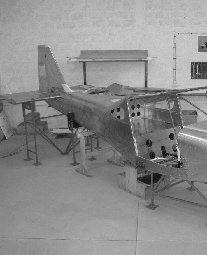
217 216
218 INSTALLATION OF THE HORIZONTAL STABILIZER 217 Assembly identification: SH TM
219 EMPENNAGE Table of parts for the installation of the horizontal stabilizer Assembly identification: INSTALLATION SH Bar code: Position: 2 Lug on the fuselage Part s identification: SH Bar code: Position: 3 Horizontal stabilizer Part s identification: SH Bar code: NOTE Complete assembly as the subassembly of the installation of the horizontal stabilizer Table: Bolts, screw nuts, washers and rivets used for the installation of the horizontal stabilizer Position Name Description Rivet 5/ AN3-5A Bolt 3/ AN Washer 3/16 7 AN A Screw nut 3/16 8 AN4-5A Bolt 1/4-5 9 AN Washer 1/4 10 AN A Screw nut 1/4 218
220 (Intentionally left blank) 219
221 INSTALLATION OF THE VERTICAL STABILIZER 220 Assembly identification: INSTALLATION SV
222 EMPENNAGE Table of parts for the installation of the vertical stabilizer Assembly identification: INSTALLATION SV Bar code: Position: 2 Vertical stabilizer Part s identification: SV Bar code: NOTE Complete assembly as the subassembly of the installation of the vertical stabilizer Position: 4 Rear connection of the vertical stabilizer Part s identification: SV Bar code: Position: 5 Reinforcement of the rear connection of the vertical stabilizer Part s identification: SV Bar code: Position: 6 Middle lug Part s identification: SV Bar code: Position: 7 Stiffening of the rear connection of the vertical stabilizer Part s identification: SV Bar code:
223 Table of parts for the installation of the vertical stabilizer Assembly identification: INSTALLATION SV Bar code: Position: 8 Outer tail lug Part s identification: KP Bar code: Position: 9 Inner tail lug Part s identification: KP Bar code: Position: 11 Profile of the tail ski left Part s identification: KP L Bar code: Position: 12 Profile of the tail ski right Part s identification: KP R Bar code: Position: 13 Teflon of the tail ski Part s identification: KP Bar code:
224 EMPENNAGE Table of parts for the installation of the vertical stabilizer Assembly identification: INSTALLATION SV Bar code: Table: Bolts, screw nuts, washers and rivets used for the installation of the vertical stabilizer Position Name Description 10 K Screw nut 3/16 14 AN3-4A Bolt 3/ AN Washer 3/16 16 AN A Screw nut 3/ Rivet 1/ Rivet 5/ Rivet 5/ AN470AD4-7 Rivet S1/ AN470AD4-11 S1/ F1/
225 (Intentionally left blank) 224
226 INSTALLATION OF THE ELEVATOR 225 Assembly identification: INSTALLATION KV
227 EMPENNAGE Table of parts for the installation of the elevator Assembly identification: INSTALLATION KV Bar code: Position: 1 The elevator Part s identification: KV Bar code: NOTE Complete assembly as the subassembly of the installation of the elevator Position: 2 Upper limiter Part s identification: KV Bar code: Position: 3 Lower limiter Part s identification: KV Bar code: Table: Bolts, screw nuts, washers and rivets used for the installation of the elevator Position Name Description Rivet 1/ Rivet 5/ AN3-7A Bolt 3/ AN Washer 3/16 9 AN A Screw nut 3/16 11 AN Washer 1/4 12 AN A Screw nut 1/ Rivet 1/ Rivet F1/
228 (Intentionally left blank) 227
229 INSTALLATION OF THE RUDDER 228 Assembly identification: KP S450
230 EMPENNAGE Table of parts for the installation of the rudder Assembly identification: INSTALLATION KP Bar code: Position: 2 The rudder Part s identification: KP Bar code: NOTE Complete assembly as the subassembly of the installation of the rudder Position: 6 Tube L10mm Part s identification: C x0.032 Bar code: / Position: 7 Tube L5.6mm Part s identification: C x0.032 Bar code: / Table: Bolts, screw nuts, washers and rivets used for the installation of the rudder Position Name Description 3 AN3-10A Bolt 3/ AN Washer 3/16 5 AN A Screw nut 3/16 8 AN Washer1/4 9 AN3-6A Bolt 3/
231 (Intentionally left blank) 230

232 INSTALLATION OF THE TAIL CONTROLS 231 Assembly identification: KO C
233 EMPENNAGE Table of parts for the installation of the tail controls Assembly identification: KO C Bar code: Position: 2 Lever of the control of the nose wheel left Part s identification: KO Bar code: Position: 3 Lever of the control of the nose wheel right Part s identification: KO Bar code: Position: 4 Spherical bearing 5/16 Part s identification: MW-5 AURORA Bar code: Position: 6 Tube Part s identification: Al tube Bar code: C4730 Position: 9 Cable for the controls Part s identification: Cable INOX 1/8 7x19 SS Bar code:
234 Table of parts for the installation of the tail controls Assembly identification: KO C Bar code: Position: 10 NICOPRESS 1/8 Part s identification: 28-3-M Bar code: Position: 11 Grummet of the rope Part s identification: AN100C-4 Bar code: Position: 12 Tensioner Part s identification: AN155-16S Bar code: Position: 15 Shackle of the rope Part s identification: AN Bar code: Position: 19 Lever of the elevator Part s identification: KO Bar code:
235 EMPENNAGE Table of parts for the installation of the tail controls Assembly identification: KO C Bar code: Table: Bolts, screw nuts, washers and rivets used for the installation of the tail controls Position Name Description 5 AN315-5R Screw nut 5/16 FULL HEX 7 AN Washer 5/16 8 AN A Screw nut 5/16 16 AN3-5A Bolt 3/ AN Washer 3/16 18 AN Screw nut 3/16 20 AN5-11A Screw nut 5/
236 (Intentionally left blank) 235
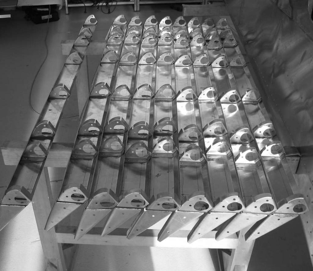
237 236
238 STRUCTURE OF THE LEFT AILERON 237 Assembly identification: KR L
239 WINGS Table of parts for the structure of the left aileron Assembly identification: KR L Bar code: Position: 1 Spar - left Part s identification: KR L Bar code: Position: 2 First nose rib left Part s identification: KR L Bar code: Position: 3 Nose rib Left Part s identification: KR L Bar code: Position: 4 Nose rib right Part s identification: KR R Bar code: Position: 5 First rib left Part s identification: KR L Bar code:
240 Table of parts for the structure of the left aileron Assembly identification: KR L Bar code: Position: 6 Second rib left Part s identification: KR L Bar code: Position: 7 Third rib left Part s identification: KR L Bar code: Position: 8 Rear rib left Part s identification: KR L Bar code: Position: 9 Lug of the aileron left Part s identification: KR L Bar code: Lug of the aileron right Part s identification: KR R Bar code: Position: 10 Table: Bolts, screw nuts, washers and rivets used for the structure of the left aileron Position Name Description Rivet 1/ Rivet 5/
241 WINGS (Intentionally left blank) 240
242 STRUCTURE OF THE RIGHT AILERON 241 Assembly identification: KR R
243 WINGS Table of parts for the structure of the right aileron Assembly identification: KR R Bar code: Position: 1 Spar - right Part s identification: KR R Bar code: Position: 2 First nose rib right Part s identification: KR R Bar code: Position: 3 Nose rib right Part s identification: KR R Bar code: Position: 4 Nose rib left Part s identification: KR L Bar code: Position: 5 First rib right Part s identification: KR R Bar code:
244 Table of parts for the structure of the right aileron Assembly identification: KR R Bar code: Position: 6 Second rib right Part s identification: KR R Bar code: Position: 7 Third rib right Part s identification: KR R Bar code: Position: 8 Nose rib right Part s identification: KR R Bar code: Position: 9 Lug of the aileron right Part s identification: KR R Bar code: Position: 10 Lug of the aileron left Part s identification: KR L Bar code: Table: Bolts, screw nuts, washers and rivets used for the structure of the right aileron Position Name Description Rivet 1/ Rivet 5/
245 WINGS (Intentionally left blank) 244
246 TRIMMER OF THE LEFT AILERON 245 Assembly identification: KR L
247 WINGS Table of parts for assembly of the trimmer of the left aileron Assembly identification: KR Bar code: Position: 1 Spar of the trimmer of the aileron Part s identification: KR Bar code: Position: 2 Rib of the trimmer of the aileron - left Part s identification: KR L Bar code: Position: 3 Rib of the trimmer of the aileron - right Part s identification: KR R Bar code: Position: 4 Lower surface of the trimmer Part s identification: KR Bar code: Position: 5 Upper surface of the trimmer Part s identification: KR Bar code:
248 Table of parts for assembly of the trimmer of the left aileron Assembly identification: KR Bar code: Position: 6 Trailing edge of the trimmer Part s identification: KR Bar code: Position: 7 Lug of the trimmer of the aileron Part s identification: KR Bar code: Position: 8 Piano hinge Part s identification: / Bar code: Table: Bolts, screw nuts, washers and rivets used for the assembly trimmer of the left aileron Position Name Description 9 Rivet Rivet 3/32 10 Fastener Fastener 3/32 247
249 WINGS (Intentionally left blank) 248
250 LEFT AILERON WITH THE TRIMMER 249 Assembly identification: KR L
251 WINGS Table of parts for the assembly of the left aileron with the trimmer Assembly identification: KR L Bar code: Position: 1 Structure of the left aileron Part s identification: KR L Bar code: NOTE Complete assembly as the subasembly of the left aileron with the trimmer Position: 2 Trailing edge of the aileron left Part s identification: KR L Bar code: Position: 3 Upper surface of the aileron - left Part s identification: KR L Bar code: Position: 4 Lower surface of the aileron Part s identification: KR Bar code: Position: 5 Inner leading edge of the aileron left Part s identification: KR L Bar code:
252 Table of parts for the assembly of the left aileron with the trimmer Assembly identification: KR L Bar code: Position: 6 Middle leading edge of the aileron left Part s identification: KR L Bar code: Position: 7 Outer leading edge of the aileron left Part s identification: KR L Bar code: Position: 8 Cover of the lug of the aileron Part s identification: KR Bar code: Position: 12 Trimmer of the left aileron Part s identification: KR Bar code: NOTE Complete assembly as the subassembly of the left aileron with the trimmer Table: Bolts, screw nuts, washers and rivets used for the assembly of the left aileron with the trimmer Position Name Description Fastener F1/ Fastener 1/ MS20470AD3-4 Fastener S3/
253 WINGS (Intentionally left blank) 252
254 RIGHT AILERON 253 Assembly identification: KR R
255 WINGS Table of parts for the assembly of the right aileron Assembly identification: KR R Bar code: Position: 1 Structure of the right aileron Part s identification: KR Bar code: NOTE Complete assembly as the subassembly of the right aileron Position: 2 Trailing edge of the aileron right Part s identification: KR R Bar code: Position: 3 Upper surface of the aileron right Part s identification: KR R Bar code: Position: 4 Lower surface of the aileron Part s identification: KR Bar code: Position: 5 Inner leading edge right Part s identification: KR R Bar code:
256 Table of parts for the assembly of the right aileron Assembly identification: KR R Bar code: Position: 6 Middle leading edge right Part s identification: KR R Bar code: Position: 7 Outer leading edge right Part s identification: KR R Bar code: Position: 8 Cover of the hinge of the aileron Part s identification: KR Bar code: Table: Bolts, screw nuts, washers and rivets used for the assembly of the right aileron Position Name Description Fastener F1/ Fastener 1/ MS20470AD3-4 Fastener S3/
257 WINGS (Intentionally left blank) 256
258 STRUCTURE OF THE LEFT FLAP 257 Assembly identification: KR L
259 WINGS Table of parts for the assembly of the structure of the left flap Assembly identification: KR L Bar code: Position: 1 Spar of the flap left Part s identification: KR L Bar code: Position: 2 First nose rib of the flap Left Part s identification: KR L Bar code: Position: 3 Nose flap rib left Part s identification: KR L Bar code: Position: 4 Nose flap rib right Part s identification: KR R Bar code: Position: 5 Guide of the aileron control lever left Part s identification: KR L Bar code:
260 Table of parts for the assembly of the structure of the left flap Assembly identification: KR L Bar code: Position: 6 Left flap lug Part s identification: KR L Bar code: Position: 7 Right flap lug Part s identification: KR R Bar code: Position: 8 First flap rib left Part s identification: KR L Bar code: Position: 9 Second flap rib left Part s identification: KR L Bar code: Position: 10 Third flap rib left Part s identification: KR L Bar code:
261 WINGS Table of parts for the assembly of the structure of the left flap Assembly identification: KR L Bar code: Position: 11 Third flap rib right Part s identification: KR R Bar code: Position: 12 Upper lever of the flap control -left Part s identification: KR L Bar code: Table: Bolts, screw nuts, washers and rivets used for the assembly of the structure of the left flap Position Name Description Fastener 5/ Fastener 1/
262 (Intentionally left blank) 261
263 STRUCTURE OF THE RIGHT FLAP 262 Assembly identification: KR R
264 WINGS Table of parts for the assembly of the structure of the right flap Assembly identification: KR R Bar code: Position: 1 Spar of the flap right Part s identification: KR R Bar code: Position: 2 First nose flap rib right Part s identification: KR R Bar code: Position: 3 Nose flap rib right Part s identification: KR R Bar code: Position: 4 Nose flap rib left Part s identification: KR L Bar code: Position: 5 Guide of the aileron control lever right Part s identification: KR R Bar code:
265 Table of parts for the assembly of the structure of the right flap Assembly identification: KR R Bar code: Position: 6 Right flap lug Part s identification: KR R Bar code: Position: 7 Left flap lug Part s identification: KR L Bar code: Position: 8 First flap rib right Part s identification: KR R Bar code: Position: 9 Second flap rib right Part s identification: KR R Bar code: Position: 10 Third flap rib right Part s identification: KR R Bar code:
266 WINGS Table of parts for the assembly of the structure of the right flap Assembly identification: KR R Bar code: Position: 11 Third flap rib left Part s identification: KR L Bar code: Position: 12 Upper lever of the flap control right Part s identification: KR L Bar code: Table: Bolts, screw nuts, washers and rivets used for the assembly of the structure of the right flap Position Name Description Fastener 5/ Fastener 1/
267 (Intentionally left blank) 266
268 LEFT FLAP 267 Assembly identification: KR L
269 WINGS Table of parts for the assembly of the left flap Assembly identification: KR L Bar code: Position: 1 Structure of the left flap Part s identification: KR L Bar code: NOTE Complete assembly as the subassembly of the left flap Position: 2 Trailing edge of the flap left Part s identification: KR L Bar code: Position: 3 Upper surface of the flap left Part s identification: KR L Bar code: Position: 4 Lower surface of the flap Part s identification: KR Bar code: Position: 5 Inner leading edge left Part s identification: KR L Bar code:
270 Table of parts for the assembly of the left flap Assembly identification: KR L Bar code: Position: 6 Middle leading edge left Part s identification: KR L Bar code: Position: 7 Outer leading edge left Part s identification: KR L Bar code: Position: 8 Cover of the flap lug Part s identification: KR Bar code: Position: 9 Leading edge of the flap up to fuselage Part s identification: KR L Bar code: Position: 10 Cover of the extension of the controls Part s identification: KR Bar code: Table: Bolts, screw nuts, washers and rivets used for the assembly of the left flap Position Name Description Fastener F1/ Fastener 1/ MS20470AD3-4 Fastener S3/ Fastener 5/
271 WINGS (Intentionally left blank) 270
272 RIGHT FLAP 271 Assembly identification: KR R
273 WINGS Table of parts for the assembly of the right flap Assembly identification: KR R Bar code: Position: 1 Structure of the right flap Part s identification: KR R Bar code: NOTE Complete assembly as the subassembly of the right flap Position: 2 Trailing edge of the flap right Part s identification: KR R Bar code: Position: 3 Upper surface of the flap right Part s identification: KR R Bar code: Position: 4 Lower surface of the flap Part s identification: KR Bar code: Position: 5 Inner leading edge right Part s identification: KR R Bar code:
274 Table of parts for the assembly of the right flap Assembly identification: KR R Bar code: Position: 6 Middle leading edge right Part s identification: KR R Bar code: Position: 7 Outer leading edge right Part s identification: KR R Bar code: Position: 8 Cover of the flap lug Part s identification: KR Bar code: Position: 9 Leading edge of the flap up to fuselage - right Part s identification: KR R Bar code: Position: 10 Cover of the extension of the controls Part s identification: KR Bar code: Table: Bolts, screw nuts, washers and rivets used for the assembly of the right flap Position Name Description Fastener F1/ Fastener 1/ MS20470AD3-4 Fastener S3/ Fastener 5/
275 WINGS (Intentionally left blank) 274
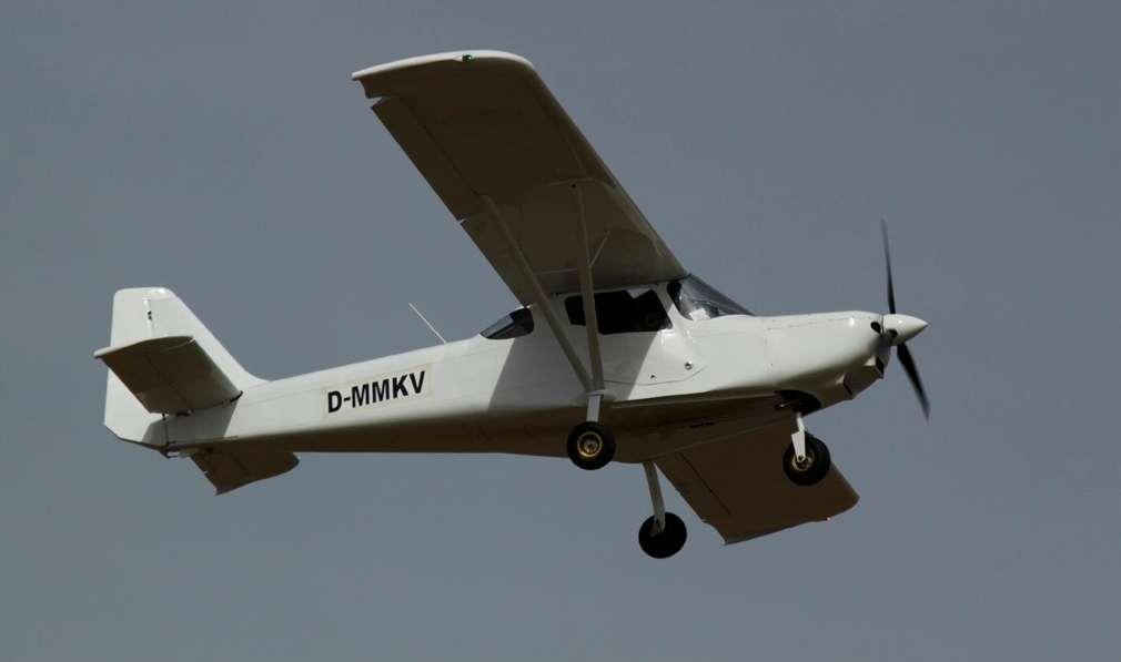
276 275
277 LEFT RIB WITH THE HINGE FOR THE FLAP 276 Assembly identification: KR L
278 WINGS Table of parts for the assembly of the left rib with the hinge for the flap Assembly identification: KR L Bar code: Position: 1 Middle rib left Part s identification: KR L Bar code: Position: 2 Hinge for the connection of the flaps Part s identification: KR Bar code: Table: Bolts, screw nuts, washers and rivets used for the assembly of the left rib with the hinge for the flap Position Name Description Fastener 5/
279 (Intentionally left blank) 278
280 RIGHT RIB WITH THE HINGE FOR THE FLAP 279 Assembly identification: KR R
281 WINGS Table of parts for the assembly of the right rib with the hinge for the flap Assembly identification: KR R Bar code: Position: 1 Middle rib at the hinge right Part s identification: KR R Bar code: Position: 2 Hinge for the connection of the flaps Part s identification: KR Bar code: Table: Bolts, screw nuts, washers and rivets used for the assembly of the right rib with the hinge for the flap Position Name Description Fastener 5/
282 (Intentionally left blank) 281
283 LEFT RIB WITH THE HINGE FOR THE AILERON 282 Assembly identification: KR L
284 WINGS Table of parts for the assembly of the left rib with the hinge for the aileron Assembly identification: KR L Bar code: Position: 1 Middle rib at the hinge left Part s identification: KR L Bar code: Position: 2 Hinge for the connection of the ailerons Part s identification: KR Bar code: Table: Bolts, screw nuts, washers and rivets used for the assembly of the left rib with the hinge for the aileron Position Name Description Fastener 5/
285 (Intentionally left blank) 284
286 RIGHT RIB WITH THE HINGE FOR THE AILERON 285 Assembly identification: KR R
287 WINGS Table of parts for the assembly of the right rib with the hinge for the aileron Assembly identification: KR R Bar code: Position: 1 Middle rib at the hinge right Part s identification: KR R Bar code: Position: 2 Hinge for the connection of the ailerons Part s identification: KR Bar code: Table: Bolts, screw nuts, washers and rivets used for the assembly of the right rib with the hinge for the aileron Position Name Description Fastener 5/
288 (Intentionally left blank) 287
289 ASSEMBLY OF THE REAR LEFT SPAR 288 Assembly identification: KR L
290 WINGS Table of parts for the assembly of the left rear spar Assembly identification: KR L Bar code: Position: 1 Rear spar left Part s identification: KR L Bar code: Position: 2 Upper inset of the rear spar left Part s identification: KR L Bar code: Position: 3 Lower inset of the rear spar left Part s identification: KR L Bar code: Position: 4 Rear lug for the connection wing-fuselage Part s identification: KR Bar code: Position: 5 Reinforcement of the connection of the rear spar and middle rib left Part s identification: KR L Bar code:
291 Table of parts for the assembly of the left rear spar Assembly identification: KR L Bar code: Position: 6 Reinforcement of the connection of the rear spar and fifth middle rib - left Part s identification: KR L Bar code: Position: 7 Lug for the connection of the rear strut Part s identification: KR Bar code: Position: 8 Reinforcement on the lug for the connection of the rear strut - left Part s identification: KR L Bar code: Table: Bolts, screw nuts, washers and rivets used for the assembly of the left rear spar Position Name Description 9 AN3-4A Bolt 3/16-4A 10 AN3-5A Bolt 3/16-5A 11 AN960-10L Washer 3/16 12 AN Screw nut 3/ Fastener 5/
292 WINGS (Intentionally left blank) 291
293 ASSEMBLY OF THE REAR RIGHT SPAR 292 Assembly identification: KR R
294 WINGS Table of parts for the assembly of the right rear spar Assembly identification: KR R Bar code: Position: 1 Rear spar right Part s identification: KR R Bar code: Position: 2 Upper inset of the rear spar right Part s identification: KR R Bar code: Position: 3 Lower inset of the rear spar right Part s identification: KR R Bar code: Position: 4 Rear lug for the connection wing-fuselage Part s identification: KR Bar code: Position: 5 Reinforcement of the connection of the rear spar and middle rib right Part s identification: KR R Bar code:
295 Table of parts for the assembly of the right rear spar Assembly identification: KR R Bar code: Position: 6 Reinforcement of the connection of the rear spar and fifth middle rib right Part s identification: KR R Bar code: Position: 7 Lug for the connection of the rear strut Part s identification: KR Bar code: Position: 8 Reinforcement on the lug for the connection of the rear strut - right Part s identification: KR R Bar code: Table: Bolts, screw nuts, washers and rivets used for the assembly of the right rear spar Position Name Description 9 AN3-4A Bolt 3/16-4A 10 AN3-5A Bolt 3/16-5A 11 AN960-10L Washer 3/16 12 AN Screw nut 3/ Fastener 5/
296 WINGS (Intentionally left blank) 295
297 ASSEMBLY OF THE LEFT FRONT SPAR 296 Assembly identification: KR L
298 WINGS Table of parts for the assembly of the left front spar Assembly identification: KR L Bar code: Position: 1 Left front spar Part s identification: KR L Bar code: Position: 2 Upper profile of the front spar left Part s identification: KR L Bar code: Position: 3 Lower profile of the front spar left Part s identification: KR L Bar code: Position: 4 Reinforcement of the front spar left Part s identification: KR L Bar code: Position: 5 Profile for the connection of the strut on the front spar left Part s identification: KR L Bar code:
299 Table of parts for the assembly of the left front spar Assembly identification: KR L Bar code: Position: 6 Lug for the connection of the front strut Part s identification: KR Bar code: Position: 7 Inset in the root of the wing Part s identification: KR Bar code: Position: 8 Reinforcement of the root of the front spar Part s identification: KR Bar code: Position: 9 Front lug for the connection wing-fuselage Part s identification: KR Bar code: Position: 10 Connection of the front spar and first nose rib left Part s identification: KR L Bar code:
300 WINGS Table of parts for the assembly of the left front spar Assembly identification: KR L Bar code: Position: 11 Connection of the front spar and first middle rib left Part s identification: KR L Bar code: Table: Bolts, screw nuts, washers and rivets used for the assembly of the left front spar Position Name Description 12 AN3-6A Bolt 3/16-6A 13 AN960-10L Washer 3/16 14 AN Screw nut 3/16 15 AN470AD6-8 Fastener S3/ AN470AD5-10 Fastener S5/ AN470AD5-8 Fastener S5/ AN470AD4-6 FastenerS1/ AN470AD4-4 Fastener S1/ K Anit Screw nut 3/ Fastener F1/ AN3-5A Bolt 3/16-5A 23 AN470AD5-7 Fastener S5/
301 (Intentionally left blank) 300
302 ASSEMBLY OF THE RIGHT FRONT SPAR 301 Assembly identification: KR R
303 WINGS Table of parts for the assembly of the right front spar Assembly identification: KR R Bar code: Position: 1 Right front spar Part s identification: KR R Bar code: Position: 2 Upper profile of the front spar right Part s identification: KR R Bar code: Position: 3 Lower profile of the front spar right Part s identification: KR R Bar code: Position: 4 Reinforcement of the front spar right Part s identification: KR R Bar code: Position: 5 Profile for the connection of the strut on the front spar right Part s identification: KR R Bar code:
304 Table of parts for the assembly of the right front spar Assembly identification: KR R Bar code: Position: 6 Lug for the connection of the front strut Part s identification: KR Bar code: Position: 7 Inset in the root of the wing Part s identification: KR Bar code: Position: 8 Reinforcement of the root of the front spar Part s identification: KR Bar code: Position: 9 Front lug for the connection wing-fuselage Part s identification: KR Bar code: Position: 10 Connection of the front spar and first nose rib right Part s identification: KR R Bar code:
305 WINGS Table of parts for the assembly of the right front spar Assembly identification: KR L Bar code: Position: 11 Connection of the front spar and first middle rib right Part s identification: KR R Bar code: Table: Bolts, screw nuts, washers and rivets used for the assembly of the right front spar Position Name Description 12 AN3-6A Bolt 3/16-6A 13 AN960-10L Washer 3/16 14 AN Screw nut 3/16 15 AN470AD6-8 Fastener S3/ AN470AD5-10 Fastener S5/ AN470AD5-8 Fastener S5/ AN470AD4-6 FastenerS1/ AN470AD4-4 Fastener S1/ K Anit Screw nut 3/ Fastener F1/ AN3-5A Bolt 3/16-5A 23 AN470AD5-7 Fastener S5/
306 (Intentionally left blank) 305
307 STRUCTURE OF THE LEFT WING 306 Assembly identification: KR L
308 WINGS Table of parts for the assembly of the structure of the left wing Assembly identification: KR L Bar code: Position: 1 Assembly of the front left spar Part s identification: KR L Bar code: NOTE Complete assembly as the subassembly of the structure of the left wing Position: 2 Assembly of the left rear spar Part s identification: KR L Bar code: NOTE Complete assembly as the subassembly of the structure of the left wing Position: 3 Rib with the lug for the flap left Part s identification: KR L Bar code: NOTE Complete assembly as the subassembly of the structure of the left wing Position: 4 Rib with the lug for the aileron left Part s identification: KR L Bar code: NOTE Complete assembly as the subassembly of the structure of the left wing Position: 5 Nose rib left Part s identification: KR L Bar code:
309 Table of parts for the assembly of the structure of the left wing Assembly identification: KR L Bar code: Position: 6 Middle rib left Part s identification: KR L Bar code: Position: 7 Nose rib - right Part s identification: KR R Bar code: Position: 8 Middle rib - right Part s identification: KR R Bar code: Position: 9 Connection between nose and middle rib Part s identification: KR Bar code: Table: Bolts, screw nuts, washers and rivets used for the assembly of the structure of the left wing Position Name Description Fastener 5/ Fastener 5/
310 WINGS (Intentionally left blank) 309
311 STRUCTURE OF THE RIGHT WING 310 Assembly identification: KR R
312 WINGS Table of parts for the assembly of the structure of the right wing Assembly identification: KR R Bar code: Position: 1 Assembly of the front right spar Part s identification: KR R Bar code: NOTE Complete assembly as the subassembly of the structure of the left wing Position: 2 Assembly of the right rear spar Part s identification: KR R Bar code: NOTE Complete assembly as the subassembly of the structure of the left wing Position: 3 Rib with the lug for the flap right Part s identification: KR R Bar code: NOTE Complete assembly as the subassembly of the structure of the left wing Position: 4 Rib with the lug for the aileron right Part s identification: KR R Bar code: NOTE Complete assembly as the subassembly of the structure of the left wing Position: 5 Nose rib left Part s identification: KR R Bar code:
313 Table of parts for the assembly of the structure of the right wing Assembly identification: KR R Bar code: Position: 6 Middle rib - right Part s identification: KR R Bar code: Position: 7 Nose rib - left Part s identification: KR L Bar code: Position: 8 Middle rib - left Part s identification: KR L Bar code: Position: 9 Connection between nose and middle rib Part s identification: KR Bar code: Table: Bolts, screw nuts, washers and rivets used for the assembly of the structure of the right wing Position Name Description Fastener 5/ Fastener 5/
314 WINGS (Intentionally left blank) 313
315 LEFT WING BOX Assembly identification: KR L 314

316 WINGS Table of parts for the assembly of the left wing box Assembly identification: KR L Bar code: Position: 1 Structure of the left wing Part s identification: KR L Bar code: NOTE Complete assembly as the subassembly of the wing box Position: 2 Cover of the reservoir Part s identification: KR Bar code: Position: 3 Inner skin of the lower surface Part s identification: KR Bar code: Position: 4 Skin of the lower surface Part s identification: KR Bar code: Position: 6 Skin of the upper surface Part s identification: KR Bar code:
317 Table of parts for the assembly of the left wing box Assembly identification: KR L Bar code: Position: 7 Inner skin of the upper surface Part s identification: KR Bar code: Table: Bolts, screw nuts, washers and rivets used for the assembly of the left wing box Position Name Description 5 DIN 7337 Fastener N1/ Fastener 1/ Fastener F1/
318 WINGS (Intentionally left blank) 317
319 RIGHT WING BOX Assembly identification: KR R 318

320 WINGS Table of parts for the assembly of the right wing box Assembly identification: KR R Bar code: Position: 1 Structure of the right wing Part s identification: KR R Bar code: NOTE Complete assembly as the subassembly of the wing box Position: 2 Cover of the reservoir Part s identification: KR Bar code: Position: 3 Inner skin of the lower surface Part s identification: KR Bar code: Position: 4 Skin of the lower surface Part s identification: KR Bar code: Position: 6 Skin of the upper surface Part s identification: KR Bar code:
321 Table of parts for the assembly of the right wing box Assembly identification: KR R Bar code: Position: 7 Inner skin of the upper surface Part s identification: KR Bar code: Table: Bolts, screw nuts, washers and rivets used for the assembly of the right wing box Position Name Description 5 DIN 7337 Fastener N1/ Fastener 1/ Fastener F1/
322 WINGS (Intentionally left blank) 321
323 BASIC LEFT WING Assembly identification: KR SL 322
324 WINGS Table of parts for the assembly of the basic left wing Assembly identification: KR SL Bar code: Position: 1 Left wing box Part s identification: KR L Bar code: NOTE Complete assembly as the subassembly of the structure of the basic left wing Position: 2 Leading edge left Part s identification: KR L Bar code: Position: 3 Inner leading edge left Part s identification: KR L Bar code: Position: 4 Carrier of the cover of the cables Part s identification: KR Bar code: Position: 5 Guide of the cables Part s identification: Standard part Bar code:
325 Table of parts for the assembly of the basic left wing Assembly identification: KR SL Bar code: Position: 6 Cable ties Part s identification: Bar code: Position: 8 Lug for the reinforcement of the lug for the connection of the front strut left Part s identification: KR L Bar code: Position: 9 Carrier of the lug for the reinforcement of the lug for the connection of the front strut - left Part s identification: KR L Bar code: Table: Bolts, screw nuts, washers and rivets used for the assembly of the basic left wing Position Name Description Fastener 1/ Fastener 5/
326 WINGS (Intentionally left blank) 325
327 BASIC RIGHT WING Assembly identification: KR SR 326
328 WINGS Table of parts for the assembly of the basic right wing Assembly identification: KR SR Bar code: Position: 1 Right wing box Part s identification: KR R Bar code: NOTE Complete assembly as the subassembly of the basic right wing Position: 2 Leading edge right Part s identification: KR R Bar code: Position: 3 Inner leading edge right Part s identification: KR R Bar code: Position: 4 Carrier of the revetment of the cables Part s identification: KR Bar code: Position: 5 Guide of the cables Part s identification: Standard part Bar code:
329 Table of parts for the assembly of the basic right wing Assembly identification: KR SR Bar code: Position: 6 Cable ties Part s identification: Bar code: Position: 8 Lug for the reinforcement of the lug for the connection of the front strut right Part s identification: KR R Bar code: Position: 9 Lug carrier for the reinforcement of the lug for the connection of the front strut - right Part s identification: KR R Bar code: Table: Bolts, screw nuts, washers and rivets used for the assembly of the basic right wing Position Name Description Fastener 1/ Fastener 5/
330 WINGS (Intentionally left blank) 329
331 LEFT WING Assembly identification: KR SL 330
332 WINGS Table of parts for the assembly of the left wing Assembly identification: KR SL Bar code: Position: 1 Basic left wing Part s identification: KR SL Bar code: NOTE Complete assembly as the subassembly of the left wing Position: 2 Left aileron Part s identification: 5751-KR L Bar code: NOTE Complete assembly as the subassembly of the left wing Position: 3 Left flap Part s identification: KR L Bar code: NOTE Complete assembly as the subassembly of the left wing Position: 4 Flange of the control on the wing left Part s identification: KR L Bar code: Position: 5 Outer drive of the aileron Part s identification: KO Bar code:
333 Table of parts for the assembly of the left wing Assembly identification: KR SL Bar code: Position: 6 Inner drive of the aileron Part s identification: KO Bar code: Position: 7 Clip of the aileron drive Part s identification: KO Bar code: Position: 8 Axial insole of the lug Part s identification: KR Bar code: Position: 9 Axial insole of the lug Part s identification: KR Bar code: Table: Bolts, screw nuts, washers and rivets used for the assembly of the left wing Position Name Description 10 AN3-10A Bolt 3/16-10A 11 AN960-10L Washer 3/16 12 AN Screw nut 3/16 13 MS20470AD3-4 Fastener S5/ Fastener 5/
334 WINGS (Intentionally left blank) 333
335 RIGHT WING Assembly identification: kr SR 334
336 WINGS Table of parts for the assembly of the right wing Assembly identification: KR SR Bar code: Position: 1 Basic right wing Part s identification: KR SR Bar code: NOTE Complete assembly as the subassembly of the right wing Position: 2 Right aileron Part s identification: KR R Bar code: NOTE Complete assembly as the subassembly of the right wing Position: 3 Right flap Part s identification: KR R Bar code: NOTE Complete assembly as the subassembly of the right wing Position: 4 Flange of the control on the wing right Part s identification: KR R Bar code: Position: 5 Outer drive of the aileron Part s identification: KO Bar code:
337 Table of parts for the assembly of the right wing Assembly identification: KR SR Bar code: Position: 6 Inner drive of the aileron Part s identification: KO Bar code: Position: 7 Clip of the aileron drive Part s identification: KO Bar code: Position: 8 Axial insole of the lug Part s identification: KR Bar code: Position: 9 Axial insole of the lug Part s identification: KR Bar code: Table: Bolts, screw nuts, washers and rivets used for the assembly of the right wing Position Name Description 10 AN3-10A Bolt 3/16-10A 11 AN960-10L Washer 3/16 12 AN Screw nut 3/16 13 MS20470AD3-4 Fastener S5/ Fastener 5/
338 WINGS (Intentionally left blank) 337
339 COMPLETE LEFT WING Assembly identification: KR SL 338
340 WINGS Table of parts for the assembly of the complete left wing Assembly identification: KR SL Bar code: Position: 1 Left wing Part s identification: KR SL Bar code: NOTE Complete assembly as the subassembly of the complete left wing Position: 2 Left reservoir Part s identification: GI L Bar code: Position: 3 Outer lower carriers of the reservoir Part s identification: KR S Bar code: Position: 4 Inner lower carriers of the reservoir Part s identification: KR U Bar code: Position: 5 Small profile for the reservoir Part s identification: KR Bar code:
341 Table of parts for the assembly of the complete left wing Assembly identification: KR SL Bar code: Position: 6 Big profile for the reservoir Part s identification: KR Bar code: Position: 7 Exit of the excess of fuel from the tube for the irradiation of reservoir Part s identification: GI Bar code: Position: 8 Smaller spacer Part s identification: KR Bar code: Not Available Position: 9 Bigger spacer Part s identification: KR Bar code: Not Available Position: 10 Clamp for the tube Part s identification: QS200-06H Bar code:
342 WINGS Table of parts for the assembly of the complete left wing Assembly identification: KR SL Bar code: Position: 11 Fuel hose Part s identification: Rubber fuel hose Bar code: Position: 12 Guide of the inlet throat Part s identification: KR Bar code: Position: 13 Support of the reservoir Part s identification: KR Bar code: Position: 14 Thermo isolator Part s identification: 155 NEOPREN Bar code: Position: 15 Wall carpet Part s identification: 155 NEOPREN Bar code:
343 Table of parts for the assembly of the complete left wing Assembly identification: KR SL Bar code: Position: 18 Rubber inlet of the cables Part s identification: MS Bar code: Table: Bolts, screw nuts, washers and rivets used for the assembly of the complete left wing Position Name Description Fastener 5/ Fastener 1/
344 WINGS (Intentionally left blank) 343
345 COMPLETE RIGHT WING Assembly identification: KR SR 344
346 WINGS Table of parts for the assembly of the complete right wing Assembly identification: KR SR Bar code: Position: 1 Right wing Part s identification: KR SR Bar code: NOTE Complete assembly as the subassembly of the complete right wing Position: 2 Right reservoir Part s identification: GI R Bar code: Position: 3 Outer lower carriers of the reservoir Part s identification: KR S Bar code: Position: 4 Inner lower carriers of the reservoir Part s identification: KR U Bar code: Position: 5 Small profile for the reservoir Part s identification: KR Bar code:
347 Table of parts for the assembly of the complete right wing Assembly identification: KR SR Bar code: Position: 6 Big profile for the reservoir Part s identification: KR Bar code: Position: 7 Exit of the excess of fuel from the tube for the irradiation of reservoir Part s identification: GI Bar code: Position: 8 Smaller spacer Part s identification: KR Bar code: Not Available Position: 9 Bigger spacer Part s identification: KR Bar code: Not Available Position: 10 Clamp for the tube Part s identification: QS200-06H Bar code:
348 WINGS Table of parts for the assembly of the complete right wing Assembly identification: KR SR Bar code: Position: 11 Fuel hose Part s identification: Rubber fuel hose Bar code: Position: 12 Guide of the inlet throat Part s identification: KR Bar code: Position: 13 Support of the reservoir Part s identification: KR Bar code: Position: 14 Thermo isolator Part s identification: 155 NEOPREN Bar code: Position: 15 Wall carpet Part s identification: 155 NEOPREN Bar code:
349 Table of parts for the assembly of the complete right wing Assembly identification: KR SR Bar code: Position: 18 Rubber inlet of the cables Part s identification: MS Bar code: Table: Bolts, screw nuts, washers and rivets used for the assembly of the complete right wing Position Name Description Fastener 5/ Fastener 1/
350 WINGS (Intentionally left blank) 349
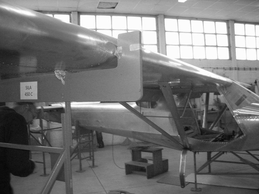
351 350
352 INSTALLATION OF WINGS Assembly Identification: KR
353 WINGS Table of parts for the installation of wings Assembly identification: KR Bar code: Position: 2 Left reinforcement on the opening for the controls Part s identification: TR L Bar code: Position: 3 Right reinforcement on the opening for the controls Part s identification: TR R Bar code: Position: 4 Left cover of the opening for the tubes Part s identification: TR L Bar code: Position: 5 Right cover of the opening for the tubes Part s identification: TR R Bar code: Position: 7 Complete left wing Part s identification: KR SL Bar code:
354 Table of parts for the installation of wings Assembly identification: KR Bar code: Position: 8 Complete right wing Part s identification: KR SR Bar code: Position: 9 Left front strut of the wing Part s identification: KR L Bar code: Position: 10 Right front strut of the wing Part s identification: KR R Bar code: Position: 11 Rear left strut of the wing Part s identification: KR L Bar code: Position: 12 Rear right strut of the wing Part s identification: KR R Bar code:
355 WINGS Table of parts for the installation of wings Assembly identification: KR Bar code: Position: 12 Lug for securing Part s identification: KR Bar code: Position: 20 Upper left lever of the control of the aileron Part s identification: KO L Bar code: Position: 21 Upper right lever of the control of the aileron Part s identification: KO D Bar code: Position: 22 Support of the controls on the first framework from the left Part s identification: TR L Bar code: Position: 23 Support of the controls on the first framework from the right Part s identification: TR R Bar code:
356 Table of parts for the installation of wings Assembly identification: KR Bar code: Position: 25 Pitot-tube Part s identification: IN Bar code: Position: 26 Hose FI8 Part s identification: HFI8 Bar code: Not Available NOTE Standard part Position: 28 Cover of the strut left-front-bottom Part s identification: KR L Bar code: Position: 29 Cover of the strut right-front-bottom Part s identification: KR R Bar code: Position: 30 Cover of the strut left-front-upper Part s identification: KR L Bar code:
357 WINGS Table of parts for the installation of wings Assembly identification: KR Bar code: Position: 31 Cover of the strut right-front-upper Part s identification: KR R Bar code: Position: 32 Cover of the strut left-rear-bottom Part s identification: KR L Bar code: Position: 33 Cover of the strut right-rear-bottom Part s identification: KR.02.84R Bar code: Position: 34 Cover of the strut left-rear-middle Part s identification: KR L Bar code: Position: 35 Cover of the strut right-rear-middle Part s identification: KR R Bar code:
358 Table of parts for the installation of wings Assembly identification: KR Bar code: Position: 36 Cover of the strut left-rear-upper Part s identification: KR L Bar code: Position: 37 Cover of the strut right-rear-upper Part s identification: KR R Bar code: Position: 38 Auxiliary strut Part s identification: KR Bar code: Position: 39 Left girder of the reinforcement of the strut Part s identification: KR L Bar code: Position: 40 Right girder of the reinforcement of the strut Part s identification: KR R Bar code:
359 WINGS Table of parts for the installation of wings Assembly identification: KR Bar code: Position: 45 Front strut cover from the left Part s identification: PL.TR Bar code: Position: 46 Front strut cover from the right Part s identification: PL.TR Bar code: Position: 47 Rear strut cover from the left Part s identification: PL.TR Bar code: Position: 48 Rear strut cover from the right Part s identification: PL.TR Bar code: Position: 53 Rubber inlet of the cables 19x36x10 Part s identification: MS Bar code: Not Available 358
360 Table of parts for the installation of wings Assembly identification: KR Bar code: Position: 54 Rubber inlet of the cables 10x16x8 Part s identification: MS Bar code: Not Available Table: Bolts, screw nuts, washers and rivets used for the installation of wings Position Name Description 6 DIN 7337 Fastener N3/ AN5-6A Bolt 5/16-6A 14 AN5-11A Bolt 5/16-11A 15 AN Washer 5/16 16 AN A Screw nut 17 AN3-12A Bolt 3/16-12A 18 AN Washer 3/16 19 AN Screw nut 3/ Fastener 5/ Fastener 1/ AN3-10A Bolt 3/ WURTH Crumpling nut M4 49 DIN 7985A A2 M4,2x20 Bolt M4,2x20 50 ANIT Screw nut K Bolt 632R8 AN R Fastener F1/ DIN Bolt M4x20 cilindrical 56 DIN Washer M4 359
361 WINGS (Intentionally left blank) 360
362 361
363 INSTALLATION OF THE WING TIPS Assembly identification: TE M 362
364 WINGS Assembly identification: TE M Bar code: Table of parts for the installation of the wing tips Position: 1 Left wing tip Part s identification: PL.KR.02.01S Bar code: Position: 2 Right wing tip Part s identification: PL.KR.02.02S Bar code: Position: 3 Upper left profile for the connection of the wing tips Part s identification: KR Bar code: Position: 4 Lower left profile for the connection of the wing tips Part s identification: KR Bar code: Position: 5 Upper right profile for the connection of the wing tips Part s identification: KR Bar code:
365 Assembly identification: TE M Bar code: Table of parts for the installation of the wing tips Position: 6 Lower right profile for the connection of the wing tips Part s identification: KR Bar code: Table: Bolts, screw nuts, washers and rivets used for the installation of the wing tips Position Name Description 7 DIN 7337 Fastener N1/ Fastener F1/
366 WINGS (Intentionally left blank) 365
367 INSTALLATION OF THE VERTICAL TAIL TIP Assembly identification: TE M 366
368 WINGS Table of parts for the installation of the vertical tail tip Assembly identification: TE M Bar code: Position: 1 Tip of the vertical tail Part s identification: PL.KP Bar code: Position: 2 Rib for the connection of the tip of the rudder Part s identification: KP Bar code: Table: Bolts, screw nuts, washers and rivets used for the installation of the vertical tail tip Position Name Description Fastener F1/
369 (Intentionally left blank) 368
370 INSTALLATION OF THE HORIZONTAL TAIL TIPS (ELEVATOR) Assembly identification: TE M 369
371 WINGS Table of parts for the installation of the horizontal tail tips - elevator Assembly identification: TE M Bar code: Position: 1 Left tip of the horizontal tail Part s identification: PL.KV L Bar code: Position: 2 Right tip of the horizontal tail Part s identification: PL.KV R Bar code: Position: 3 Rib for the connection of the elevator tips Part s identification: KV Bar code: Table: Bolts, screw nuts, washers and rivets used for the installation of the elevator tips Position Name Description 4 Rivet Rivet 1/8 370
372 (Intentionally left blank) 371
373 INSTALLATION OF THE HORIZONTAL TAIL TIPS (STABILIZER) Assembly identification: / 372
374 WINGS Assembly identification: / Bar code: / Table of parts for the installation of the horizontal tail tips - stabilizer Position: 1 Left tip of the horizontal tail Part s identification: PL.KV L Bar code: Position: 2 Right tip of the horizontal tail Part s identification: PL.KV R Bar code: Position: 3 Left upper inset of the tip Part s identification: SH L-01 Bar code: Position: 4 Left lower inset of the tip Part s identification: SH L-02 Bar code: Position: 5 Right upper inset of the tip Part s identification: SH R-01 Bar code:
375 Table of parts for the installation of the horizontal tail tips - stabilizer Assembly identification: TE M Bar code: Position: 6 Right lower inset of the tip Part s identification: SH R-02 Bar code: Table: Bolts, screw nuts, washers and rivets used for the installation of the horizontal stabilizer tips Position Name Description 7 Rivet Rivet 1/8 374
376 WINGS (Intentionally left blank) 375
377 376
378 INSTALLATION OF THE NOSE LEG 377 Assembly identification: ST ST
379 LANDING GEAR Table of parts for the installation of the nose leg Assembly identification: ST ST Bar code: Position: 1 Nose leg Part s identification: ST Bar code: Position: 2 Shock absorber Part s identification: 1080 Bar code: Position: 5 Plate of the nose leg Part s identification: ST Bar code: Position: 6 Angular profile reinforcement of the upper sheet metal of the nose leg Part s identification: KB Bar code: Position: 7 Glider of the lower carrier of the nose leg front Part s identification: KB P Bar code:
380 Table of parts for the installation of the nose leg Assembly identification: ST ST Bar code: Position: 8 Glider of the lower carrier of the nose leg rear Part s identification: KB Z Bar code: Position: 9 Lower sheet metal of the lower carrier of the nose leg Part s identification: KB Bar code: Position: 13 Girder of the upper bearing of the nose leg Part s identification: KB Bar code: Position: 14 Upper bearing of the nose leg Part s identification: AXK 5578 INA Bar code: Position: 16 Bolt of the shock absorber Part s identification: ST Bar code:
381 LANDING GEAR Table of parts for the installation of the nose leg Assembly identification: ST ST Bar code: Position: 19 Plate of the bearing Part s identification: AS 5578 INA Bar code: Position: 20 Lower carrier of the nose leg Part s identification: KB Bar code: Position: 21 Spacer Part s identification: ST Bar code: Position: 22 Reinforcement of the lower carrier of the nose leg right Part s identification: KB R Bar code: Position: 23 Reinforcement of the lower carrier of the nose leg left Part s identification: KB L Bar code:

382 Table of parts for the installation of the nose leg Assembly identification: ST ST Bar code: Position: 24 Fork of the nose wheel Part s identification: ST Bar code: Position: 25 Axle of the nose wheel Part s identification: ST Bar code: Position: 27 Front wheel Part s identification: 6X Bar code: Position: 28 Inner tire Part s identification: 15X STANDARD Bar code: Position: 29 Tire Part s identification: 15X STANDARD SAVA Bar code: Table: Bolts, screw nuts, washers and rivets used for the installation of the nose leg Position Name Description 3 DIN 1313 Bolt I M6x25 4 DIN 9021 Securing washer 10 AN3-7A Bolt 3/16-7A 11 AN Washer 3/16 12 AN A Screw nut 3/16 17 DIN 9021 Washer FI8 18 AN Cutter pin 3/
383 LANDING GEAR (Intentionally left blank) 382
384 INSTALLATION OF THE MAIN LANDING GEAR 383 Assembly identification: ST TF
385 LANDING GEAR Table of parts for the installation of the main landing gear Assembly identification: ST TF Bar code: Position: 1 Leg of the main landing gear left Part s identification: ST L Bar code: Position: 2 Leg of the main landing gear right Part s identification: ST R Bar code: Position: 7 Axle of the wheel left Part s identification: ST L Bar code: Position: 8 Axle of the wheel right Part s identification: ST R Bar code: Position: 9 Inner tire Part s identification: 15X STANDARD Bar code:

386 Table of parts for the installation of the main landing gear Assembly identification: ST TF Bar code: Position: 10 Tire Part s identification: 15x STANDARD SAVA Bar code: Position: 11 Wheel with Al braking system Part s identification: MARC INGEGNO Bar code: Position: 12 Securing screw nut M24x1.5 Part s identification: ST Bar code: Position: 13 Securing screw nut M20x1 Part s identification: ST Bar code: Table: Bolts, screw nuts, washers and rivets used for the installation of the main landing gear Position Name Description 3 AN5-14A Bolt 5/16-14A 4 AN970-5 Big washer 5/16 5 AN Washer 5/16 6 AN A Screw nut 5/16 385
387 LANDING GEAR (Intentionally left blank) 386
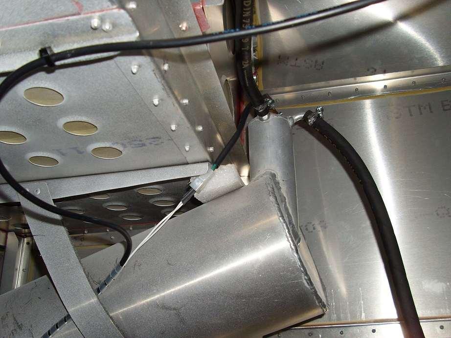
388 387

389 INSTALLATION OF THE FUEL SYSTEM 1,2 1, SILA 450C SPARE PARTS CATALOG Assembly identification: GI M 388
The tie to tube front windshield was rounded to avoid a distorted by this point.
 CHANGES IN AIRFRAME IBIS MAGIC GS-700 (2.008) Drilling of plastic polycarbonate drill with 9/64 so that it is an amplitude when riveting. The tie to tube front windshield was rounded to avoid a distorted
Mooney Mite M-18X Plans and Drawings Index Arranged by Group Miscellaneous Group
 Miscellaneous Group 110470 Bushings - Special 314410 Airspeed & Altimeter Installation 110190 Arm - Landing Warning 110070 Button - Static Airspeed 213260 Cone - Wing Fillet 110120 Control - Placard 616100
Chapter 3: Aircraft Construction
 Chapter 3: Aircraft Construction p. 1-3 1. Aircraft Design, Certification, and Airworthiness 1.1. Replace the letters A, B, C, and D by the appropriate name of aircraft component A: B: C: D: E: 1.2. What
T-51 Mustang - 3/4 Scale Kit
 T-51 Mustang - 3/4 Scale Kit Description Titan Aircraft is pleased to offer the T-51D Mustang. This P-51D replica incorporates material and systems not commonly found in comparably priced aircraft. This,
Begun 09 September 2008 Airworthy 04 December 2009
 RV-3B N3NU - HACK JOB - HIGHLIGHTS Begun 09 September 2008 Airworthy 04 December 2009 First flight 11 December 2009 384 work days, 2,298 shop hours, and 12,837 net rivets Air Venture 2010 Champion Bronze
Introduction. Fuselage/Cockpit
 Introduction The Moravan Zlin 242L is a fully aerobatic 2 seat aircraft designed to perform all advanced flight maneuvers within an envelope of -3.5 to +6 Gs. Many military and civilian flight-training
TEMPORARY REVISION NUMBER
 TEMPORARY REVISION NUMBER 8 DATED 1 DECEMBER 2011 MANUAL TITLE MANUAL NUMBER - PAPER COPY TEMPORARY REVISION NUMBER 1978 Thru 1986 Model R182 & TR182 Service Manual D2069-3-13 D2069-3TR8 MANUAL DATE 15
OCT/NOV Texas Flying Legends P-47D-23RA
 OCT/NOV Texas Flying Legends P-47D-23RA by Chuck Cravens The first joined large assemblies on the bench. Update In October and November, for the first time we began some assembly of the major components
TEMPORARY REVISION NUMBER
 TEMPORARY REVISION NUMBER 7 DATED 1 DECEMBER 2011 MANUAL TITLE MANUAL NUMBER - PAPER COPY TEMPORARY REVISION NUMBER FR172 Reims Rocket 1968 Thru 1976 Service Manual D849-5-13 D849-5TR7 MANUAL DATE 15 August
Type Approval of the Cyclone AX3/503 3 Axis Microlight Aeroplane and Approval for a Permit to Fly
 AIRWORTHINESS APPROVAL NOTE NO: 23042 APPLICANT: AIRCRAFT TYPE: REGISTRATION NO: Cyclone Airsports Ltd Cyclone AX3/503 G-MYER CONSTRUCTOR'S NO: CA 001 Type Approval of the Cyclone AX3/503 3 Axis Microlight
TEMPORARY REVISION NUMBER
 TEMPORARY REVISION NUMBER 7 DATED 1 DECEMBER 2011 MANUAL TITLE MANUAL NUMBER - PAPER COPY TEMPORARY REVISION NUMBER Model 188 & T188 Series 1966 Thru 1984 Service Manual D2054-1-13 D2054-1TR7 MANUAL DATE
TYPE-CERTIFICATE DATA SHEET
 Issue: 02 Date: 27 October 2017 TYPE-CERTIFICATE DATA SHEET NO. EASA. A.616 for Type Certificate Holder M&D Flugzeugbau GmbH & Co. KG Streeker Straße 5 b 26446 Friedeburg Germany For models: JS-MD 1C TE.CERT.00135-001
V - Speeds. RV-10 V fe Flaps Speeds Trail (0 deg) Half (15 deg) Full (30 deg) 122 kias 96 kias. 80 kias
 Half (15 deg) Full (30 deg) 122 kias 96 kias. 80 kias") RV-10 Check List V - Speeds RV-10 V fe Flaps Speeds Trail (0 deg) Half (15 deg) Full (30 deg) 122 kias 96 kias 87 kias V s1 Stall (Flap Up) 60 kias V s0 Stall (Flap 40 deg) 55 kias Best Glide 80 kias V
RV-10 Check List V - Speeds RV-10 V fe Flaps Speeds Trail (0 deg) Half (15 deg) Full (30 deg) 122 kias 96 kias 87 kias V s1 Stall (Flap Up) 60 kias V s0 Stall (Flap 40 deg) 55 kias Best Glide 80 kias V
CHAPTER 2 THE TUTOR. Introduction
 CHAPTER 2 THE TUTOR Introduction 1. AEFs. The Royal Air Force has 12 units throughout the country known as Air Experience flights (AEFs). Their role is to provide air experience flying for cadets and they
TYPE-CERTIFICATE DATA SHEET
 TYPE-CERTIFICATE DATA SHEET NO. EASA.A.616 for Type Certificate Holder M&D Flugzeugbau GmbH & Co. KG Streeker Straße 5 b 26446 Friedeburg Germany For models: JS-MD 1C TE.CERT.00135-001 European Union Aviation
Van s Aircraft RV-7A. Pilot s Operating Handbook N585RV
 Van s Aircraft RV-7A Pilot s Operating Handbook N585RV PERFORMANCE SPECIFICATIONS SPAN:..25 0 LENGTH...20 4 HEIGHT:.. 7 10 SPEED: Maximum at Sea Level...180 knots Cruise, 75% Power at 8,000 Ft...170 knots
Civil Aviation Authority Czech Republic
 TCDS 92-01 L 13 SL Vivat Page 1 of 12 Civil Aviation Authority Czech Republic CAA CZ TYPE-CERTIFICATE DATA SHEET L 13 SL Vivat Type Certificate Holder: EVEKTOR, spol. s r.o. Letecká 1008 CZECH REPUBLIC
N398CM. RC-3 Serial Number 387 Zero Timed Restoration Details
 RC-3 Serial Number 387 Zero Timed Restoration Details WING GROUP: Complete disassembly of wings, flaps, ailerons, lift struts, floats, and float struts. removal, alodine dip, and epoxy prime, w/bms 10-11.
CHECKLIST 1969 CESSNA 172-K. NOTE: Verify all information with airplane's POH
 CHECKLIST 1969 CESSNA 172-K NOTE: Verify all information with airplane's POH PRE-FLIGHT INSPECTION 1 CABIN 1 A.R.R.O.W. CHECK Airworthiness Cert. In Clear View Registration In Clear View Radio License
Grob Twin Astir. Checklist And Quick Reference
 Grob Twin Astir Checklist And Quick Reference Normal Procedures Airspeeds For Normal Operations (mph) Solo Dual Best Glide (VL/D) _57 69_ Minimum Sink (VMS) _46 56_ Maneuvering (VA) _105 105_ Never Exceed
Issue 0/Rev.00-0 Aug Page /
 Issue 0/Rev.00-0 Aug 0 4 06 4 4 4 35 6 09 3 05 0 0 Page /5 04 08 9 8 Issue 0/Rev.00-0 Aug 0 3 40 3 33 6 35 34 34 33 30 3 0 3 Page /5 3 6 4 40 Issue 0/Rev.00-0 Aug 0 65 6 40 48 36 06 08 5 69 66 0 99 5 55
European Aviation Safety Agency
 TCDS EASA.IM.A.162 Page 1/9 European Aviation Safety Agency EASA TYPE-CERTIFICATE DATA SHEET Tupolev TU 204-120CE Manufacturer: Tupolev PSC 17, Tupolev Embankment 111250 Moscow Russia For model: TU 204-120CE
MD - RA. Minister s Delegates - Recreational Aviation Représentants du Ministre - Aviation de Loisir Service d Inspection
 Think Safety Inspection Service MD - RA Pensons Sécurité Minister s Delegates - Recreational Aviation Représentants du Ministre - Aviation de Loisir Service d Inspection 51% Amateur Determination Checklist
Cessna 172P PPL Checklist Page 1
 Cessna 172P PPL Checklist 06-08-2017 Page 1 Cessna 172P PPL Checklist 06-08-2017 Page 2 Checklist Items Informational Items Critical Memory Items PREFLIGHT COCKPIT CHECK (DO-LIST) Pitot Cover -- REMOVE
European Aviation Safety Agency
 Page 1 of 9 European Aviation Safety Agency EASA TYPE-CERTIFICATE DATA SHEET APM 20 and APM 30 series Type Certificate Holder: BP 1 Manufacturer: BP 1 For variants: APM 20 APM 30 Issue 3 : 23 December
SD3-60 AIRCRAFT MAINTENANCE MANUAL. This chapter includes information on dimensions, areas, zoning, etc. and is presented as follows:
 AMM 6-00-00 1.0.0.0GENERAL 1. General This chapter includes information on dimensions, areas, oning, etc. and is presented as follows: Measurements and Figures which show the stations of fuselage frames,
JODEL D.112 INFORMATION MANUAL C-FVOF
 JODEL D.112 INFORMATION MANUAL C-FVOF Table of Contents I General Description...4 Dimensions:...4 Powertrain:...4 Landing gear:...4 Control travel:...4 II Limitations...5 Speed limits:...5 Airpeed indicator
Table of content. Illustrated Parts Cataloque XA42 XA41
 Table of content ATA Page Content 23 3 Communication 24 4 Electrical System 25 7 Equipment and Furnishings 27 11 Flight Controls 28 18 Fuel 31 20 Indicating / Recording Systems 32 23 Landing Gear 34 27
European Aviation Safety Agency
 European Aviation Safety Agency EASA TYPE-CERTIFICATE DATA SHEET VSO 10 Type Certificate Holder: Schempp-Hirth výroba letadel spol. s r.o U Dvořiska 1733 565 01 Choceň EASA TCDS No. A.442 For variants:
PIPER CUB J3-65 N68952 PRE-FLIGHT CHECKLIST
 PRE-FLIGHT CHECKLIST COCKPIT Check airworthiness certificate, registration, weight & balance documentation Battery - CONNECTED Plug in headsets or secure as required Fuel ON Primer CLOSED & LOCKED Carb
A Simplified Index of Mooney M-18 Drawings at the NASM
 A Simplified Index of Mooney M-18 Drawings at the NASM Dwg. No. Dwg. date Title Models Remarks IDnum Price 0000 23-Aug-54 M-18 Aileron Crank Mooney M-18 17 x 22 DD-0029487 $2.10 0000 [Lower Pick-Up Strap
MD RA Minister's Delegates - Recreational Aviation Représentants du Ministre - Aviation de loisir
 Think Safety Pensons Securite MD RA Minister's Delegates - Recreational Aviation Représentants du Ministre - Aviation de loisir Inspection Service Service d'inspection MDRA C20 MANUAL of PROCEDURES for
Cessna 172RG WARNING. Maximum Demonstrated Crosswind. Takeoff or landing..15 KTS
 Cessna 172RG INTRODUCTION: This aircraft checklist contains information from the original manufacturer s Pilot Information Manual. Normal procedures associated with optional systems can be found in Section
European Aviation Safety Agency
 Page 1 of 7 European Aviation Safety Agency EASA TYPE-CERTIFICATE DATA SHEET EASA.A.045 Type Certificate Holder: Blanik Aircraft CZ s.r.o. Karolinská 661/4 186 00 Praha 8 For models: Issue 05: 10 January
Flight Procedures Aero AT-3 R100
 Flight Procedures Page: 1 1. FOREWORD... 3 2. FLIGHT PREPARATION... 3 3. PRE-FLIGHT CHECK... 3 3.1. External inspection:... 4 3.2. In the cockpit... 4 3.3. Left wing... 5 3.4. Engine nacelle, canopy and
This manual contains information necessary for operation and maintenance of the airplane S/N 033/2013 according to UL 2, CS-VLA and LSA regulation.
 This manual contains information necessary for operation and maintenance of the airplane S/N 033/2013 according to UL 2, CS-VLA and LSA regulation. BRM AERO S.R.O. VÁCLAVA KULÍŠKA 1224 686 05 UHERSKÉ HRADIŠTĚ,
LAA TYPE ACCEPTANCE DATA SHEET TADS 385 BRISTELL NG5 SPEED WING
 Issue 2 Revised elevator trim tab deflections Dated 11/3/15 JV Revision A Amended fuel tank capacity, addition of Dated 7/5/15 JV Jabiru engine, amended agent website address Revision B Correction of Jabiru
The Flamingo. Produced by the Metal Aircraft Corporation. Cincinnati, Ohio. Lunken Airfield. by Peter Bruemmer
 The Flamingo Produced by the Metal Aircraft Corporation Cincinnati, Ohio Lunken Airfield by Peter Bruemmer The prototype Flamingo was a Thomas E Halpin development that was designed and engineered by Ralph
2.11 Other Equipment and Installations
 2.10 Tow Releases The tow release fitted at the C. G. is model TOST "Europa G 88" (Data Sheet No: 60.230/2). Models TOST "Europa G 72 or G 73" may be used as a replacement tow release. The forward tow
Fuselage tunel SD Washer pos. 8, set 22,78 27, Bush pos. 9, pair 12,06 14, Bush pos. 10, pair 12,06 14,35
 PRICE LIST OF SD-1 Minisport Parts Valid from 1.1.-31.12.2018 P/N Composite parts VK netto inkl. MWSt 101001 Wing tip, pair 314,90 374,73 101002 Elevator tip, pair 54,94 65,38 101003 Fuel tank complete
European Aviation Safety Agency
 TCDS No. EASA.A.044 L 23 SUPER-BLANÍK Page 1 of 8 European Aviation Safety Agency EASA TYPE-CERTIFICATE DATA SHEET EASA.A.044 L 23 SUPER-BLANÍK Type Certificate Holder: Blanik Aircraft CZ s.r.o. Karolinská
MOONEY MITE AIRCRAFT DRAWINGS NASM Archives Accession No HOW TO ORDER COPIES OF DRAWINGS
 SI-382712 BLUEPRINT MOONEY MITE AIRCRAFT DRAWINGS NASM Archives Accession No.1989-0028 HOW TO ORDER COPIES OF DRAWINGS NASM s collection of Mooney M-18 Mite drawings is available to restorers, researchers,
Van s Aircraft RV-4. Pilot s Operating Handbook
 Van s Aircraft RV-4 Pilot s Operating Handbook PERFORMANCE SPECIFICATIONS SPAN:.. 23 0 LENGTH:. 19 9 HEIGHT:. 6 8 SPEED: Maximum at Sea Level.. Cruise, 75% Power at 8,000 Ft.. 173 Knots 165 Knots RANGE
LANCAIR LEGACY PRE-TEST FLIGHT INSPECTION (8-04)
") LANCAIR LEGACY PRE-TEST FLIGHT INSPECTION (8-04) OWNER PHONE # ADDRESS N SERIAL # AIRCRAFT TYPE DATE / / TACH TIME hrs. TOTAL TIME hrs. EMPTY WEIGHT CG. PAINT & INTERIOR? YES NO ENGINE TYPE PROPELLER ALL
LANCAIR LEGACY PRE-TEST FLIGHT INSPECTION (8-04) OWNER PHONE # ADDRESS N SERIAL # AIRCRAFT TYPE DATE / / TACH TIME hrs. TOTAL TIME hrs. EMPTY WEIGHT CG. PAINT & INTERIOR? YES NO ENGINE TYPE PROPELLER ALL
European Aviation Safety Agency
 European Aviation Safety Agency EASA TYPE-CERTIFICATE DATA SHEET Schleicher ASW 28 Manufacturer: Alexander Schleicher GmbH & Co Segelflugzeugbau Models: ASW 28 ASW 28-18 Page 1 2 3 4 5 6 7 Issue 1 1 1
CIVIL AVIATION AUTHORITY OF THE CZECH REPUBLIC
 CIVIL AVIATION AUTHORITY OF THE CZECH REPUBLIC 69-04 Revision 6 MORAVAN-AEROPLANES a.s. Model Z 526 F 11.04.2007 TYPE CERTIFICATE DATA SHEET No. 69-04 This data sheet which is a part of Type Certificate
INTRODUCTION. This Catalog:
 Editor s Note: This Parts Catalog has been reproduced from the original Republic Parts Catalog. Obviously, most of the information is obsolete; the pictures are accurate and up-to-date. If nothing else,
Dassault Aviation FALCON 7 X. for Jet CAT P160. Assembly Manual. AVIATION Design
 Dassault Aviation FALCON 7 X for Jet CAT P160 Assembly Manual AVIATION Design ZI le chenet, 91490 Milly La Foret, FRANCE Tel : 33 1 64 98 93 93 Fax : 33 1 64 98 93 88 E-mail : aviation.design@wanadoo.fr
Thank you again, Jim McCormick. Jabiru Pacific LLC
 Thank you for your inquiry about Jabiru Aircraft. Jabiru Aircraft PTY, Ltd, produces a line of kit aircraft that are among the most extensively tested and thoroughly developed kit planes in the entire
12.0 CONTROLS 3/3/2006. Page 1
 Page 1 Page 2 SR3500 Rudder Pedal Parts List ITEM DESCRIPTION PART NUMBER QTY 1 MASTER BRAKE PEDAL RP0015 2 2 SLAVE BRAKE PEDAL RP0016 2 3 PUSH ROD RP0017 4 4 SLAVE BRAKE TORQUE TUBE RP0018 2 5 MASTER
1 Planning Information
 Flight Design GmbH Rudder Centering Fork - Control Stop Replacement 1 Planning Information 1.1 Affected Aircraft Type: Model: Serial Number: Applicable Countries: CT CTLS F-08-04-09, F-08-04-10, F-08-04-11,
Accident Prevention Program
 Accident Prevention Program Maintenance Aspects of Owning Your Own Airplane Introduction As an owner-pilot, FAR Part 43 allows you to perform certain types of inspections and maintenance on your airplane.
Seabee Annual Inspection Procedures
 Procedures Due to the wide variety of Seabee s flying out there, these procedures should be modified to fit YOUR Seabee. Make sure that all AD s are complied with as well as any required Service Bulletins
Expanded Flight Checklist Cessna 152
 OUTSIDE CHECK INSIDE CABIN 1 Magnetos... OFF 2 Mixture... IDLE CUT OFF 3 Master switch... ON 4 Fuel quantity... CHECKED 5 Master switch... OFF OUTSIDE CABIN 1 Left wing... CHECKED Surface condition Flap
Chapter 34. Navigation
 Chapter 34 Navigation PAGE 1 TABLE OF CONTENTS Chapter Title 34-00-00 GENERAL................................................................................................................ 3 34-10-00
Airworthiness Directive Schedule
 Airworthiness Directive Schedule Gliders 26 September 2013 Notes 1. This AD schedule is applicable to gliders manufactured under Luftfahrt-Bundesamt (LBA) Type Certificate Numbers: Aircraft Model: LBA
DIAMOND DA40 PILOTS MANUAL
 DIAMOND DA40 PILOTS MANUAL INTRODUCTION THIS IS THE SLEEK AND FUTURISTIC DIAMOND STAR DA40 XLS BY DIAMOND AIRCRAFT CORPORATION. THE DIAMOND STAR FEATURES 4 SEATS, AND OPTIONAL EXPANDED REAR CARGO AREA,
TARIF SD-1 "Pièces détachées" 1/7
 TARIF SD-1 "Pièces détachées" 1/7 Composite parts 101001 Wing tip, pair 228,00 275,88 101002 Elevator tip, pair 39,00 47,19 101003 Fuel tank complete 279,00 337,59 101004 Cabine hood 198,00 239,58 101005
Airworthiness Directive Schedule
 Airworthiness Directive Schedule Aeroplanes 22 February 2018 Notes: 1. This AD schedule is applicable to Socata TB9 (Tampico), TB10 (Tobago) and TB20 (Trinidad) aircraft manufactured under EASA Type Certificate
Revision Status AMM C3 2/1/2009 C OF A 7/15/2002 Revision Status AFM C6 12/1/ INSPECTION REQUIREMENT
 Date: 4.29.10 AFTT: 2353.7 Reg# N427JS AFTC: 3100 Ser# BB-1801 HOBBS: 2353.7 #1 Eng PT6A-42 TSN: 2353.7 TSO: N/A TSHSI: 588.1 Ser# PCE-PJ0630 CSN: 3100 CSO: N/A CSHSI: 978 #2 Eng PT6A-42 TSN: 2353.7 TSO:
Airworthiness Directive Schedule
 Airworthiness Directive Schedule Aeroplanes 27 October 2011 Notes 1. This AD schedule is applicable to aircraft manufactured under Federal Aviation Administration (FAA) Type Certificate No. A18SO. 2. The
LAA TYPE ACCEPTANCE DATA SHEET TADS 818 BOLKOW BO-208A2 JUNIOR, BO-208C JUNIOR. Issue 1 Initial Issue Dated 24/01/18 JP
 Issue 1 Initial Issue Dated 24/01/18 JP This TADS is intended as a summary of available information about the type and should be used during the build, operation and permit revalidation phases to help
Best Glide 75 kias (Max Gross)
") CESSNA 172XP CHECKLIST PREFLIGHT (Interior) 1. ACFT DOCS / INSPECTIONS--------CHECK 2. TACH TIME-----------------------------RECORD 3. CONTROL LOCK---------------------REMOVE 4. ELEVATOR / RUDDER TRIM------------
CESSNA 172XP CHECKLIST PREFLIGHT (Interior) 1. ACFT DOCS / INSPECTIONS--------CHECK 2. TACH TIME-----------------------------RECORD 3. CONTROL LOCK---------------------REMOVE 4. ELEVATOR / RUDDER TRIM------------
TORNADO II, S, & SS FUSELAGE TRACKING
 TORNADO II, S, & SS FUSELAGE TRACKING 92-INS-0176-C Nose Fork Assembly Instructions Approved 92-INS-0178-D Spindle and Brake Assembly Approved 92-INS-0181-F Anti Servo Control Assembly Approved 92-INS-0182-C
Flight Procedures. Viper SD-4. CAVOK Aviation Training Ltd.
 Viper SD-4 CAVOK Aviation Training Ltd. Page: 1 1. FOREWORD... 2 2. FLIGHT PREPARATION... 2 3. PRE-FLIGHT CHECK... 3 3.1. In the cockpit... 3 3.2. Left side of the fuselage... 4 3.3. Empennage... 5 3.4.
PIPER AIRCRAFT PA NOTE- Perform all inspections or operations at each oj the inspection. 1. Inspectspinnerandbackplate
 PPER ARCRAFT PA-38-111 (.MANTENANCE MANUAL SCHEDULED MANTENANCE. PERODC NSPECTONS. -NOTE- Perform all inspections or operations at each oj the inspection intervals as indicated by a circle (). nspection
DCS [Fw 190 D-9] 2 INTRODUCTION
![DCS [Fw 190 D-9] 2 INTRODUCTION](/thumbs/74/70879519.jpg "DCS [Fw 190 D-9] 2 INTRODUCTION") DCS [Fw 190 D-9] INTRODUCTION The D for Dora variant of the famous Fw 190 fighter was nicknamed the Long-Nose by German pilots as well as the Allies. It was a departure from the radial-engine earlier variants
DCS [Fw 190 D-9] INTRODUCTION The D for Dora variant of the famous Fw 190 fighter was nicknamed the Long-Nose by German pilots as well as the Allies. It was a departure from the radial-engine earlier variants
NORMAL CHECKLIST ATTENTION!
 Avion Training CHECKLIST Normal Checklist CESSNA 172R / TC-STS Cessna 172 R TC-STS NORMAL CHECKLIST ATTENTION! DO NOT STOW THIS CHECKLIST IN DIRECT SUNLIGHT Avion Training - Doc.nr. 212 Revision 1 / 02022018
RAF BULLDOG MODIFICATION INDEX T Mk 1 SERIES
 RAF BULLDOG MODIFICATION INDEX T Mk 1 SERIES ification Title Class Comments 1 1.4.73 Extension of Flap Shrouds B2 2 4.4.73 Resistor Part No 11212E (ITT Ltd) in Supply to Integral Lighting on CCS Panel
TYPE CERTIFICATE DATA SHEET 2A10
 DEPARTMENT OF TRANSPORTATION FEDERAL AVIATION ADMINISTRATION 2A10 Revision 23 LAVIA S.A. PA-25 PA-25-235 PA-25-260 TYPE CERTIFICATE DATA SHEET 2A10 November 30, 2000 This data sheet which is a part of
Flight Manual DG-300. No. page description issue date. 2 4, 17, 21, 33 Installation of an additional tow hook TN Oct. 85
 Flight Manual DG-300 Manual amendments No. page description issue date 1 1, 2, 4-6, 8, 10- amendments and corrections TN 359/7 May 85 12, 15, 16, 19, 21, 22, 24, 25, 28, 30, 31, 33 2 4, 17, 21, 33 Installation
CAP10. European Aviation Safety Agency EASA TYPE-CERTIFICATE DATA SHEET EASA.A.370 CAP10. Type Certificate Holder CEAPR
 Page 1 of 10 European Aviation Safety Agency EASA TYPE-CERTIFICATE DATA SHEET EASA.A.370 Type Certificate Holder 1 Route de Troyes 21121 DAROIS FRANCE For models: B Issue 07: 15 September 2016 EASA Form
CIVIL AVIATION AUTHORITY SAFETY REGULATION GROUP MICROLIGHT TYPE APPROVAL DATA SHEET (TADS) NO: BM 19 ISSUE: 6. Shadow Series BD
 NO: BM 19 ISSUE: 6. Shadow Series BD") Shadow Series BD 1 MANUFACTURER CFM Aircraft Ltd (ceased trading) BMAA is responsible for continued airworthiness 2 UK IMPORTER None 3 CERTIFICATION BCAR Section S Advance Issue dated March 1983. List
Shadow Series BD 1 MANUFACTURER CFM Aircraft Ltd (ceased trading) BMAA is responsible for continued airworthiness 2 UK IMPORTER None 3 CERTIFICATION BCAR Section S Advance Issue dated March 1983. List
CHAPTER 10 PARKING AND MOORING
 CHAPTER 10 PARKING AND MOORING P/N 135A-970-100 Chapter 10 REVISION ~ Page 1 of 12 Copyright 2009 All rights reserved. The information contained herein is proprietary to Liberty Aerospace, Incorporated.
TYPE-CERTIFICATE DATA SHEET
 TYPE-CERTIFICATE DATA SHEET NO. EASA.A.607 for BS 115 Type Certificate Holder BLACKSHAPE S.P.A. Strada Statale 16 KM 841+900 70043 Monopoli (BA) ITALY For models: BS 115 TE.CERT.00048-001 European Aviation
LIST OF MANDATORY BULLETINS FOR L 410 UVP AIRCRAFT
 LIST OF MANDATORY BULLETINS FOR L 410 UVP AIRCRAFT ------------------------------------------------------------------------------------------------------------------------------- No. Description Effectiveness
MOONEY MITE AIRCRAFT DRAWINGS NASM Archives Accession No HOW TO ORDER COPIES OF DRAWINGS
 SI-382712 BLUEPRINT MOONEY MITE AIRCRAFT DRAWINGS NASM Archives Accession No.1989-0028 HOW TO ORDER COPIES OF DRAWINGS NASM s collection of Mooney M-18 Mite drawings is available to restorers, researchers,
Vr V STANDARD EQUIPMENT LIST
 Vr V5.02.09 STANDARD EQUIPMENT LIST IMPORTANT NOTE: this document is a general description of the aircraft equipment only. It is not a technical document and is to be used only for the purpose of generally
CIVIL AVIATION AUTHORITY SAFETY AND AIRSPACE REGULATION GROUP MICROLIGHT TYPE APPROVAL DATA SHEET (TADS) NO: BM-82 ISSUE: 2
 NO: BM-82 ISSUE: 2") TYPE: EV-97 Eurostar SL Microlight (1) MANUFACTURER: Light Sport Aviation Ltd, Wycombe Air Park, Hangar 1, Booker, Marlow, Buckinghamshire, SL7 3DP (2) UK IMPORTER: N/A (3) CERTIFICATION: BCAR Section
TYPE: EV-97 Eurostar SL Microlight (1) MANUFACTURER: Light Sport Aviation Ltd, Wycombe Air Park, Hangar 1, Booker, Marlow, Buckinghamshire, SL7 3DP (2) UK IMPORTER: N/A (3) CERTIFICATION: BCAR Section
HU-16 Albatross USER MANUAL. Virtavia HU-16 Albatross DTG Steam Edition Manual Version 1.0
 HU-16 Albatross USER MANUAL 0 Introduction The Grumman HU-16 Albatross is a twin-engine amphibious flying boat. First flown in 1949, the HU-16 underwent a number of modifications and improvements over
PIPER CUB J3-65 N68952 PRE-FLIGHT CHECKLIST COCKPIT
 PIPER CUB J3-65 N68952 PRE-FLIGHT CHECKLIST COCKPIT Check airworthiness certificate, registration, weight & balance documentation Battery - CONNECTED Plug in headsets or secure as required Fuel ON Magnetos
SAVAGE OUTBACK N1300
 1 of 8 P age FIREWALL FORWARD Titan, Fuel Injected, IO-340CC Engine, 180 hp Catto composite Climb Propeller with metal leading edge Dynamically Balanced Prop, backing plate, and Spinner Spin-on oil filter
Instruction Manual BULLDOG. Wingspan : 1410 mm (55.5in) : 1450 mm (57.1in) : 4900gr gr. Weight. : 6-9 Channel/ 7 servo high torque, 1standard
 : 1450 mm (57.1in) : 4900gr gr. Weight. : 6-9 Channel/ 7 servo high torque, 1standard") Wingspan : 1410 mm (55.5in) Length Weight Radio Engine : 1450 mm (57.1in) : 4900gr - 5600gr : 6-9 Channel/ 7 servo high torque, 1standard : 1.20/ 2 stroke 1.80/ 4 stroke KIT CONTENTS: We have organized
Wingspan : 1410 mm (55.5in) Length Weight Radio Engine : 1450 mm (57.1in) : 4900gr - 5600gr : 6-9 Channel/ 7 servo high torque, 1standard : 1.20/ 2 stroke 1.80/ 4 stroke KIT CONTENTS: We have organized
Cessna 172 Skyhawk. Aircraft Checklist Models: R & S
 Cessna 172 Skyhawk Aircraft Checklist Models: R & S This is an abbreviated checklist. Most explanatory items, notes cautions and warnings have been omitted for brevity. Procedures in red/bold text in this
PAC 750XL PAC 750XL PAC-750XL
 PAC 750XL The PAC 750XL combines a short take off and landing performance with a large load carrying capability. The PAC 750XL is a distinctive type. Its design philosophy is reflected in the aircraft's
European Aviation Safety Agency
 TCDS EASA.A.510 C.E.A.P.R. DR 200 Page 1 of 21 European Aviation Safety Agency EASA TYPE-CERTIFICATE DATA SHEET EASA.A.510 DR 200 series Type Certificate Holder: C.E.A.P.R. 1 route de Troyes 21121 DAROIS
Section 1.4 FINAL INSPECTION
 File Number MDRA C20 MANUAL of PROCEDURES for INSPECTION of METAL, TUBE, FABRIC and WOOD AMATEUR-BUILT AIRCRAFT, INSPECTION AND TECHNICAL INFORMATION RECORD Section 1.4 FINAL INSPECTION GENERAL 1. Have
LAA TYPE ACCEPTANCE DATA SHEET TADS 317 AEROPRAKT A22 FOXBAT AND A22-L FOXBAT
 Issue 3 Max continuous rpm limitation added with dated 25.4.07 Kiev 263/1700 propeller fitted 1. UK Agent Ray Everitt, Dragon Aviation, Chirk Airfield, Wrexham, tel 07974 952118 (kit previously supplied
CESSNA SECTION 4. Unless otherwise noted, the following speeds are based on a maximum weight of 2550 pounds and may be used for any lesser weight.
 CESSNA SECTION 4 INTRODUCTION Section 4 provides procedures and amplified instructions for normal operations using standard equipment. Normal procedures associated with optional systems can be found in
M-4-180V S2 M-4-180V S4. MAULE AIR, INC GA Hwy 133 South, Moultrie, GA / Phone (229) /
 /") M-4-180V S2 M-4-180V S4 MAULE AIR, INC. 2099 GA Hwy 133 South, Moultrie, GA 31788 / Phone (229) 985-2045 / www.mauleairinc.com Models, Equipment, Colors and Other Items Are Subject To Change At Any Time
M-4-180V S2 M-4-180V S4 MAULE AIR, INC. 2099 GA Hwy 133 South, Moultrie, GA 31788 / Phone (229) 985-2045 / www.mauleairinc.com Models, Equipment, Colors and Other Items Are Subject To Change At Any Time
TYPE CERTIFICATE DATA SHEET 2A8
 DEPARTMENT OF TRANSPORTATION FEDERAL AVIATION ADMINISTRATION TYPE CERTIFICATE DATA SHEET 2A8 2A8 Revision 20 LAVIA S.A. PA-25 PA-25-235 PA-25-260 November 30, 2000 This data sheet which is part of Type
LAA TYPE ACCEPTANCE DATA SHEET TADS 193 RANS S4 AND RANS S5 (B WING AND C WING)
") Issue 2 MOD/193/006 added, ref tail bracing wire tang cracking. dated 13.06.07 1. UK contact Skycraft Ltd., Kestrel, Broadgate, Weston Hills, Spalding. Lincs. PE12 6DP. United Kingdom Telephone: 01406
Issue 2 MOD/193/006 added, ref tail bracing wire tang cracking. dated 13.06.07 1. UK contact Skycraft Ltd., Kestrel, Broadgate, Weston Hills, Spalding. Lincs. PE12 6DP. United Kingdom Telephone: 01406
CIVIL AVIATION AUTHORITY OF THE CZECH REPUBLIC
 CIVIL AVIATION AUTHORITY OF THE CZECH REPUBLIC 6 208/60 Revision 4 Aircraft Industries, a.s L 200 A 05.09.2005 TYPE CERTIFICATE DATA SHEET No. 6 208/60 This data sheet which is a part of Type Certificate
Jabiru Aircraft Pty. Ltd. Final Inspection Checklist. Engine Compartment
 Jabiru Aircraft Pty. Ltd. Final Inspection Checklist Registration No: Aircraft Checklist Pre Ground Test Model: Serial No: Engine Compartment Propeller: Prop Size: 60 x 53 Other:.. Propeller Serial No:
DEPARTMENT OF TRANSPORTATION FEDERAL AVIATION ADMINISTRATION TYPE CERTIFICATE DATA SHEET NO. 1A13
 DEPARTMENT OF TRANSPORTATION FEDERAL AVIATION ADMINISTRATION TYPE CERTIFICATE DATA SHEET NO. 1A13 1A13 Revision 27 Revo, Inc. COLONIAL C-1 COLONIAL C-2 LAKE LA-4 LAKE LA-4A LAKE LA-4P LAKE LA-4-200 LAKE
CIVIL AVIATION AUTHORITY OF THE CZECH REPUBLIC
 CIVIL AVIATION AUTHORITY OF THE CZECH REPUBLIC 74-01 Revision 5 MORAVAN-AEROPLANES a.s. Model Z 726 Model Z 726 K 11.04.2007 TYPE CERTIFICATE DATA SHEET No. 74-01 This data sheet, which is a part of Type
Airframe Group Item Description Part Number Size
 Parts List: LS-1 Airframe Group Canopy - LS1 Aluminum sheet, 6061 T6 1241-8.050" x 1.5" 8" Angle, aluminum 6061-T6 987-6 2" x 2" x.125" 6" Bar stock, acetal 42367 1" x 1.25" 3" Bar stock, alum 1125-8 1"
FLASHCARDS AIRCRAFT. Courtesy of the Air Safety Institute, a Division of the AOPA Foundation, and made possible by AOPA Services Corporation.
 AIRCRAFT FLASHCARDS Courtesy of the Air Safety Institute, a Division of the AOPA Foundation, and made possible by AOPA Services Corporation. Knowing your aircraft well is essential to safe flying. These
TYPE-CERTIFICATE DATA SHEET
 TYPE-CERTIFICATE DATA SHEET NO. EASA.A.610 for Type Certificate Holder Game Composites Ltd. Ground Floor Flat 56 Queen s Gate, London, SW7 5JW, United Kingdom For models: TE.CERT.00048-001 European Aviation
DEPARTMENT OF TRANSPORTATION FEDERAL AVIATION ADMINISTRATION RESTRICTED AIRCRAFT SPECIFICATION NO. AR-7
 DEPARTMENT OF TRANSPORTATION FEDERAL AVIATION ADMINISTRATION RESTRICTED AIRCRAFT SPECIFICATION NO. AR-7 AR-7 Revision 10 PIPER PA-18A PA-18A "135" PA-18A "150" April 23, 1996 Type Certificate Holder The