Dhanalakshmi College of Engineering
|
|
|
- Shon Butler
- 5 years ago
- Views:
Transcription

1 Dhanalakshmi College of Engineering Tambaram, Chennai DEPARTMENT OF ELECTRICAL AND ELECTRONICS ENGINEERING EE ELECTRICAL MACHINES LABORATORY - I III SEMESTER - R 2017 LABORATORY MANUAL Name : RegisterNo. : Section :
2 DHANALAKSHMI COLLEGE OF ENGINEERING VISION Dhanalakshmi College of Engineering is committed to provide highly disciplined, conscientious and enterprising professionals conforming to global standards through value based quality education and training. MISSION To provide competent technical manpower capable of meeting requirements of theindustry To contribute to the promotion of Academic Excellence in pursuit of Technical Education at differentlevels To train the students to sell his brawn and brain to the highest bidder but to never put a price tag on heart andsoul DEPARTMENT OF ELECTRICAL AND ELECTRONICS ENGINEERING VISION To strive for acquiring, applying and imparting knowledge in Electrical and Electronics Engineering through quality education and to provide enthusiastic professionals with commitment MISSION To educate the students with the state-of-art technologies to meet the growing challenges of the electronicsindustry Tocarryoutresearchthroughcontinuousinteractionwithresearchinstitutesandindustry,onadvancesincommunication systems To provide the students with strong ground rules to facilitate them for systematic learning, innovation and ethical practices 1 Format No.: DCE/Stud/LM/34/Issue:00/Revision:00
3 PROGRAMME EDUCATIONAL OBJECTIVES (PEOs) 1. Fundamentals To impart students with fundamental knowledge in Mathematics, Science and fundamentals of Engineering that will would them to be successfulprofessionals 2. CoreCompetence To provide students with sound knowledge in engineering and experimental skills to identify complex software problems in industry and to develop practical solution forthem 3. Breadth To provide relevant training and experience to bridge the gap between theory and practice this enables to find solutions for real time problem in industry and organization and to design products requiring interdisciplinary skills 4. Professionalismskills To bestow students with adequate training and provide opportunities to work as team that will build up their communication skills, individual leadership and supportive qualities and to develop them to adapt and work in ever changing technologies 5. Lifelong Learning To develop the ability of students to establish themselves as professionals in Electrical and Electronics Engineering and to create awareness about the need for lifelong learning and pursuing advanced degrees 2 Format No.: DCE/Stud/LM/34/Issue:00/Revision:00
4 PROGRAMME OUTCOMES (POs) a) TodemonstrateandapplyknowledgeofMathematics,ScienceandengineeringfundamentalsinElectricaland Electronics Engineeringfield b) Todesignacomponent,asystemoraprocesstomeetthespecificneedswithintherealisticconstraintssuch as economics, environment, ethics, health, safety andmanufacturability c) Todemonstratethecompetencytousesoftwaretoolsforcomputation,simulationandtestingofelectricaland electronics engineeringcircuits d) To identify, formulate and solve electrical and electronics engineeringproblems e) To demonstrate an ability to visualize and work on laboratory and multidisciplinarytasks f) To function as a member or a leader in multidisciplinaryactivities g) To communicate in verbal and written form with fellow engineers and society atlarge h) TounderstandtheimpactofElectricalandElectronicsEngineeringinthesocietyanddemonstrateawareness of contemporary issues and commitment to give solutions exhibiting socialresponsibility i) To demonstrate professional & ethicalresponsibilities j) To exhibit confidence in self-education and ability for lifelonglearning k) To participate and succeed in competitiveexams 3 Format No.: DCE/Stud/LM/34/Issue:00/Revision:00
5 EE8311- ELECTRICAL MACHINES I LABORATORY SYLLABUS COURSE OBJECTIVES To validate the principles studied in theory by performing experiments in the laboratory LIST OF EXPERIMENTS 1. Open circuit and load characteristics of DC shunt generator- criticalresistance. 2. Load characteristics of DC compound generator with differential and cumulativeconnections. 3. Load test on DC shunt and compoundmotor. 4. Load test on DC seriesmotor. 5. Swinburne s test and speed control of DC shuntmotor. 6. Hopkinson s test on DC motor generatorset. 7. Load test on single-phase transformer and three phasetransformers. 8. Open circuit and short circuit tests on single phasetransformer. 9. Polarity Test and Sumpner s test on single phasetransformers. 10. Separation of no-load losses in single phasetransformer. 11. Study of starters and 3-phase transformersconnections. COURSE OUTCOMES 1. Ability to perform the Open circuit and load characteristics of DC shunt generator- criticalresistance. 2. Ability to understand the Load characteristics of DC compound generator with differential and cumulative connections. 3. Ability to perform the Load test on DC shuntcontrol 4. Ability to perform the load test on compoundmotor. 5. To perform the Load test on DC seriesmotor. 6. Ability to perform the Swinburne stest 7. Ability to perform the DC shuntmotor. 8. Ability to perform the Hopkinson s test on DC motor generatorset. 9. Ability to perform the Load test on single-phasetransformer. 10. Ability to perform the Load test on three-phasetransformer. 11. Ability to perform the Open circuit and short circuit tests on single phasetransformer. 12. Ability to perform the Polarity test on single phasetransformers. 13. Ability to perform the Sumpner s test on single phasetransformers. 14. Ability to perform the Separation of no-load losses in single phasetransformer. 15. Ability to study the different types of starters and 3-phase transformersconnections. 4 Format No.: DCE/Stud/LM/34/Issue:00/Revision:00
6 EE8311 ELECTRICAL MACHINES - I LABORATORY CONTENTS Sl.No. Name of the Experiment Page No. CYCLE 1 Experiments 1 Open circuit and load characteristics of DC shunt generator. 2 Load characteristics of DC compound generator with differential and cumulative connections. 3 Load test on DC shunt motor 2 Load test on DC compound motor. 3.Load test on DC series motor 4 Swinburne s test of a DC shunts motor 5 Speed control of a DC shunt motor ADDITIONAL EXPERIMENTS BEYOND THE SYLLABUS 6 Load Test on DC series generator CYCLE 2 Experiments 7 Hopkinson s test on DC motor generator set. 8 Load test on a single phase transformer 9 Load test on three phase transformer. 10 Open circuit and short circuit tests on a single phase transformer 11 Polarity Test on single phase transformers. 12 Sumpner s test on single phase transformers 13 Separation of no-load losses in single phase transformer 14 Study of DC and Induction motor starters 5 Format No.: DCE/Stud/LM/34/Issue:00/Revision:00
7 Expt.No.1 OPEN CIRCUIT AND LOAD CHARACTERISTICS OF DC SHUNT GENERATOR Aim: To obtain open circuit characteristics and load characteristics of a DC shunt generator and find its critical resistance Apparatus required: SL. No. Name of the equipment Range & Type Quantity Circuit Diagram: Fuse rating Name plate details 6 Format No.:DCE/Stud/LM/34/Issue:00/Revision:00
8 Circuit diagram for find the generator armature resistance [Ra] Precautions: 1. The field rheostat of motor should be in minimum resistance position. 2. The field rheostat of generator should be in maximum resistance position. 3. No load should be connected to generator at the time of starting the experiment. 4. The SPST switch in the generator field circuit should be kept open at the time of starting the experiment. Procedure: Open circuit test: 1. Make circuit as per the circuit diagram. 2. Close the DPST switch on motor side and motor start with the help of starter. 3. Adjust the motor field rheostat, till the runs at its generator rated speed. 4. Note down The voltage induced due to residual flux in the voltmeter connected across the armature circuit. Close the SPST switch in field circuit of the generator. 5. The generator field rheostat in steps. At each step note down ammeter and voltmeter readings. 6. Repeat the above procedure till the voltmeter reads rates field current of the generator. 7. Reduce the terminal voltage of generator by varying generator field rheostat. 8. Reduce the speed of the motor by varying motor field rheostat. Load test: 1. Adjust field rheostat of generator till armature induced emf reaches its rated voltage. 2. Close the DPST switch on generator load side. 3. Varytheloadinsteps, foreachstepofloadnotedowntheloadcurrent, fieldcurrent, terminalvoltage. Maintain the rated speed of the generation at each step of load. 4. Vary the load till ammeter reads the rated current of generator. 7 Format No.: DCE/Stud/LM/34/Issue:00/Revision:00
9 5. Remove the load on generator in steps and open DPST switch on generator side. 6. Vary Generator field rheostat to make generator and terminal voltage zero. Vary the motor field rheostat to reduce the motor speed. 7. Open the DPST switch on supply side. To find armature resistance R a : 1. Load on the loading arrangement should be zero. 2. ClosetheDPSTSwitchandvarytheresistiveloadforvariousvaluesandnotedownthecorresponding values. 3. Open the DPST switch after load brings to its initial condition. Observation: Open circuit test: SL. No. Field Current If (A) Armature Voltage Eo (V) Load test: SL. No. Field Current If (A) Load Current IL (A) Terminal Voltage (V) Ia = IL + If (A) Eg =V + Ia Ra (V) 1 To find armature resistance Ra: SL. No. Armature voltage Va in volts Armature current (Ia) in amps Ra = Va/ Iain ohms Calculation: Eg = V + IaRa (V) Ia = IL + If (A) [for self Excited] Armature Resistance-Ra: Where ohm Eg V : Generated EMF in V : Terminal Voltage in V Ia : Armature Current in A 8 Format No.: DCE/Stud/LM/34/Issue:00/Revision:00
10 IL : Line Current in A If : Field Current in A Ra : Armature Resistance in Ohm Model graph: Open Circuit test load test Result: Thus the open circuit characteristics and load characteristics of a self-excited DC shunt generator were plotted and its critical resistance was obtained. 9 Format No.: DCE/Stud/LM/34/Issue:00/Revision:00
11 Outcome: By conducting the open circuit test and load test the open circuit characteristics and load characteristics of a DC shunt generator with its critical resistance was understood. Applications: Shunt generators are used in supplying nearly constant loads. They are used for battery charging, for supplying the fields of synchronous machines and separately excited DC machines. Viva voce 1. How can you find the residual voltage of the generator? 2. State Faradays law of electromagnetic induction and interaction. 3. What is the difference you can see experimentally between self excited and separately excited? 4. If any other prime mover can be used in this experiment? 5. What is a magnetization characteristic of DC generator? 6. What is meant by critical resistance of a generator? 7. What is meant by critical speed? 8. Why in a DC machine, the armature core should be laminated? 9. What are the applications of DC shunt generator? 10. What will be the no load emf, when the no load speed changes to 1000rpm? 11. What happen if the field current of the DC motor varies during load test? 12. What are the factors which represent the nature of external characteristics in DC shunt generator? 13. When load increases there is fall in generated voltage why? 14. What is the effect of armature reaction on external and internal characteristics of DC shunt generator? 10 Format No.: DCE/Stud/LM/34/Issue:00/Revision:00
12 Aim: Expt. No.2.LOAD CHARACTERISTICS OF DC COMPOUND GENERATOR WITH DIFFERENTIAL AND CUMULATIVE CONNECTIONS To conduct the load test on the given DC compound generator with cumulative and differential connections. Apparatus required: SL. No. Name of the equipment Range & Type Quantity Circuit diagram: Name Plate details 11 Format No.: DCE/Stud/LM/34/Issue:00/Revision:00
13 Precautions: 1. All the switches should be kept open at the time of starting. 2. The field rheostat of the motor should be kept at minimum resistance position. 3. The field rheostat of the generator should be kept at maximum resistance position. Procedure: 1. Make the connections are made as per the circuit diagram. 2. Close the DPST switch on motor side. 3. Start the motor using four point starter. 4. Adjust the field rheostat of the motor to bring the motor speed to the rated speed of the generator. 5. Adjust the generator field rheostat till the voltmeter reads the rated voltage of the generator. 6. Close the DPST switch on generator. 7. Increase the load insteps. 8. At each step of loading, Note down the load current and load voltage. 9. The above procedure is repeated till the rated current. 10. Switchofftheloadgraduallyandmakethemotorandgeneratorrheostatresistancepositionasinstructed in the precaution. 11. Open the DPST switch on generator side and turn on motor 12. Interchange the terminal connection of the generator series field coil and repeat the procedure right from step. Observation: Cumulative Compound SL. NO. IL(A) VL(V) Differential Compound SL. NO. IL(A) VL(V) 12 Format No.: DCE/Stud/LM/34/Issue:00/Revision:00
14 Model graph: Result: Thus the performance characteristics of the given DC compound generator were drawn for differential and cumulative connection. Outcome: The performance characteristics of the DC compound generator in cumulative and differential mode were verified. Applications: Cumulative Compound wound Generators are generally used Lighting, power supply purpose and for heavy power services because of their constant voltage property. Viva voce 1. Mention the basic requirements for the production of emf. 2. What causes sparking at the brushes? 3. Which rule gives the direction of induced emf? 4. Classify compound generator. 5. What is the relationship between flux and induced emf? 6. What is meant by armature reaction? 7. Differentiate over excitation and under excitation. 8. What are the applications of DC compound generator? 9. How can u compensate the fall in terminal voltage of a DC generator? 10. What will be the voltage across the shunt field winding of a level compound generator? 11. What will be the voltage across the shunt field winding in long shunt and short shunt connection? 12. Which type of compound generator will give drooping characteristics? 13. Can the series field and shunt field can be interchanged? 13 Format No.: DCE/Stud/LM/34/Issue:00/Revision:00
15 Expt. No.3 LOAD TEST ON DC SHUNT MOTOR Aim: To obtain the performance characteristics of the given D.C. shunt motor by conducting load test. Apparatus required: SL. No. Name of the equipment Range & Type Quantity Theory: The performance of DC shunt motor such as torque, efficiency and speed with respect to output power can be determined by conducting an actual load test. This type of test is conducted on small capacity machines normally in the laboratories to study the behavior of the motor for different load conditions. The frictional load is introduced and the speed decreases and back emf reduces which will increase the current taken by the motor from the supply. Likewise for different frictional loads the motor parameters such as speed, torque and efficiency are studied. Circuit diagram: Fuse rating Name plate details 14 Format No.: DCE/Stud/LM/34/Issue:00/Revision:00
16 Precautions: 1. DC shunt motor should be started and stopped under no load condition. 2. Field rheostat should be kept in the minimum position. 3. Brake drum should be cooled with water when it is under load. Procedure: 1. Make connections as per the circuit diagram. 2. Close the DPST switch and start motor using 3 point starter. 3. Adjust the field rheostat of the motor and run the motor at its rate speed. 4. Note down the Ammeter, Voltmeter readings, speed and spring balance readings under no load condition. 5. Increase the load on the motor in steps and at each step of load note down voltmeter, ammeter, spring balance readings and measure the speed of the motor. 6. Repeat the above procedure till ammeter reads 125%of the rated current. 7. Decrease the load on the motor & reduce the speed by adjusting motor field rheostat. 8. Open the DPST switch. Observation: Circumference of the Brake drum = cm. Sl.No Voltage VL (Volts) Current I L(Amps) Spring Balance Reading S= S1 S2(Kg) S1 (Kg) S2 (Kg) Speed N (rpm) Torque T (Nm) Input Power Pi (Watts) Output Power Po (Watts) Efficiency % 15 Format No.: DCE/Stud/LM/34/Issue:00/Revision:00
17 Calculation: 1. Circumference = 2 π r= Radius = r =Circumference / (2 π) = meter 2. Torque ( T )=S*9.81*r Nm 3. Input Power (Pi) = VL * ILwatts 4. Output power (Po) = 2πNT/60watts 5. Efficiency (η) = (Output power / Input power) X 100% Where, S - Load r Radius of brake drum.vl Line Voltage IL Line current N Speed in rpm T Torque in Nm Model graph: (a)electrical characteristics (b) Mechanical characteristics N I T % in % T in N-m Speed in rpm IL in amps Speed (N) in rpm T Vs N Output powerinwatts Torque ( T) inn-m 16 Format No.: DCE/Stud/LM/34/Issue:00/Revision:00
18 Result: Thus the load test on DC shunt motor was performed and its characteristics were drawn. Outcome: By conducting the load test on DC shunt motor the efficiency and the following performance characteristics: 1) Efficiency vs Output power (2) Torque vs Output power (3) Speed vs Output Power (4) Line current vs Output Power (5) Torque vs Speed were understood. Applications: The various applications of DC shunt motor are in Lathe Machines, Centrifugal Pumps, Fans, Blowers, Conveyors, Lifts, Weaving Machine, Spinning machines, etc Viva voce 1. What is the need for a starter? 2. Why a DC shunt motor is called a constant Speed motor? 3. State few applications of DC shunt motor. 4. How to reverse the direction of rotation of DC shunt motor? 5. Why the field rheostat of DC motor is kept at minimum resistance position while starting? 6. What are the mechanical and electrical characteristics of a DC shunt motor? 7. What is back emf in a dc motor? 8. How the input current increases as load increases? 9. What will be the effect of armature reaction in performance of dc shunt motor? 17 Format No.: DCE/Stud/LM/34/Issue:00/Revision:00
19 Expt. No.4 LOAD TEST ON DC COMPOUND MOTOR Aim: To draw the performance characteristics of the given DC compound motor by conducting load test. Apparatus Required: SL. No. Name of the equipment Range & Type Quantity Differentially Compounded motor: In this motor, the flux produced by both Field windings opposes each other. The graph between VL and IL is the External characteristic of the motor. The graph between E and Ia is the Internal characteristic of the motor. Circuit diagram: Fuse rating Name plate details 18 Format No.:DCE/Stud/LM/34/Issue:00/Revision:00
20 Precautions: 1. The motor field rheostat should be kept at minimum resistance position at the time of starting. 2. The DPST switch and be kept in open position. Procedure: 1. Circuit connections make the as per the circuit diagram. 2. Close the DPST switch. 3. State the motor using 4 point starter. 4. Adjust the motor field rheostat to get the rated speed. 5. Note down the ammeter, voltmeter spring balance reading at no loads and space. 6. The load in steps and note down voltmeter, ammeter, spring balance readings & speed are noted for various loads up to the rated current. Observation: SI. No. Voltage VL (V) Current I L (A) Spring Balance S1 (Kg) Reading S2 (Kg) S=S1~S 2 (Kg) Speed N (rpm) Torque T (Nm) Input Power Pi (W) Output Power Po (W) Efficiency η% 1 Calculation: Torque (T)= (S1~S2) x R x9.81 Nm. Where, S1, S2 are spring balance readings in kg. R is Radius of brake drum in m. Input power (Pi) =VLxIL watts Where, VLis the line voltage in volts. ILis load current in A 19 Format No.:DCE/Stud/LM/34/Issue:00/Revision:00
21 Output power (Po)= (2πNT)/60 Where N is Speed of motor in rpm. T is Torque in Nm. % Efficiency= (Po / Pi) x 100 Circumference of brake drum 2π r= m Radius of brake drum= m Model Graph: Result: Result : Thus the performance characteristics of the given DC compound motor were determined. Outcome: By conducting the load test on DC compound motor, the performance characteristic was understood. Applications: Compound motors are rarely used Presses Shears, Reciprocating machine because of its poor torque characteristics. 20 Format No.:DCE/Stud/LM/34/Issue:00/Revision:00
22 Viva voce 1. What is the need for a starter? 2. State few applications of DC shunt motor. 3. What is the role of commutator in a DC motor? 4. State the principle operation of DC motor. 5. How may the direction of DC motor be able to be reversed? 6. Why the field rheostat of DC motor is kept at minimum position while starting? 7. What will happen if the field of the DC motor is opened while delivering load? 8. What will happen if both the field current and armature current are reversed? 9. Why should the field rheostat be kept in the position of minimum resistance? 10. What is the loading arrangement used in a DC motor? 11. What are the applications of a DC compound motor? 12. What is meant by torque? 21 Format No.: DCE/Stud/LM/34/Issue:00/Revision:00
23 Expt. No. 5 LOAD TEST ON DC SERIES MOTOR Aim: To obtain the performance characteristics of a DC series motor by conducting load test. Apparatus required: SL. No. Name of the equipment Range & Type Quantity Circuit diagram: Fuse rating Name plate details 22 Format No.: DCE/Stud/LM/34/Issue:00/Revision:00
24 Precautions: 1. DC series motor should be started and stopped with initial load. 2. Brake drum should be cooled with water when it is under load..procedure: 1. Make circuit as per the circuit diagram. 2. Close the DPST switch and start the motor using 2-pointstarter. 3. Note down the readings of ammeter, voltmeter, speed and spring balance readings on initial condition. 4. Increase the load on in steps the motor and at each step of load, note down voltmeter, ammeter, spring balance readings and speed of the motor. 5. Repeat the above procedure till the ammeter read the rates current of the motor. 6. Reduce the load on the motor to the initial load condition. 7. Open the DPST switch. Observation: Circumference of the Brake drum= cm. Sl.No. Voltage VL (Volts) Current I L(Amps) S1 (Kg) Spring Balance Reading S2 (Kg) S=S1 S2 (Kg) Speed N (rpm) Torque T (Nm) Input Power Pi (Watts) Output Power Po (Watts) Efficiency % 23 Format No.: DCE/Stud/LM/34/Issue:00/Revision:00
25 Calculation: 1. Radius of Brake Drum Circumference = 2 π r= Radius =r R=Circumference / (2 π) = meter 2. Torque ( T )=S*9.81*r Nm 3. Input Power (Pi) = VL * IL watts 4. Output power (Po) = 2πNT/60watts 5. Efficiency (η) = Output power / Input power X 100 % Where, S - Load r Radius of brake drum. VL Line Voltage IL Line current N Speed in rpm T Torque in Nm. Result: Thus the load test on DC series motor was performed and its characteristics were drawn. Outcome: By conducting the load test on DC series motor the efficiency and the following performance characteristics: 1) Efficiency vs Output power (2) Torque vs Output power (3) Speed vs Output Power (4) Line current vs Output Power (5)Torque vs Speed were understood. Applications: DC series motors are basically used where the requirement is high starting torque. In earlier days, it was used in cranes, lift, etc.. But in low power applications, series dc motors which can also be used as universal motors (motors which work both on ac and dc) are used like mixer, grinder, etc. 24 Format No.: DCE/Stud/LM/34/Issue:00/Revision:00
26 Viva voce 1. Why a DC series motor should not be stared without load? 2. Why a DC series motor has a high starting torque? 3. Compare the resistances of the field windings of DC shunt and series motor? 4. What are the applications of DC series motor? 5. Comment on the Speed Torque characteristics of a DC series motor. 6. What is the precaution to be taken when working with a D.C series motor? 7. What is the need for starter with a D.C motor? 8. How does a 2-point starter function? 9. Explain the shape of the electrical and mechanical characteristics. 10. What is the condition for maximum efficiency in a D.C motor? 11. What are the different losses occurring in a D.C machine? 12. How are the meter ratings selected for this experiment? 13. Give some applications of D.C series motor 25 Format No.: DCE/Stud/LM/34/Issue:00/Revision:00
27 Expt. No.6 SWINBURNE S TEST OF A DC SHUNT MOTOR Aim: To predetermine the efficiency of the given DC shunt machine while running as a motor and as a generator by conducting Swinburne s test Apparatus required: Sl.No. Apparatus Name Range Type Quantity Precautions: 1. The field rheostat should be kept at minimum resistance position. 2. There should be no load on the brake down at the time of starting the experiment. Procedure: 1. Make the connections as per the circuit diagram. 2. Close the DPST switch and start the motor using three point starter. 3. Adjust the motor field rheostat is adjusted to run the motor at rated speed. 4. At rated speed, note down the values of line voltage, no load current. 5. Calculateandtabulateheefficiencyofthemachineasamotorandasageneratorforeachassumedload current up to rated current. 6. Drawn the characteristic curve between the output power and efficiency for both the cases 26 Format No.: DCE/Stud/LM/34/Issue:00/Revision:00

28 Circuit Diagram: Fuse Rating Name Plate Details 27 Format No.: DCE/Stud/LM/34/Issue:00/Revision:00
29 Observation: Sl. No. Line voltage VL(Volts) Line current IL(A) Field current If(A) Performance of DC Machine as a Motor Armature Resistance= Line Voltage= Constant Loss= If = Armature Total Input Load Armature Output Copper loss loss Wc power Efficiency Sl. current current Ia= 2 power IL (A) il if(a) I r +wcu Vl (W) % No. (W) (W) (W) Performance of DC Machine as a Generator Armature Resistance= Line Voltage= Constant Loss= Sl. No. Load current Il(A) Armature current Ia=IL+IF (A) Armature Copperloss I2r(watts) Total loss Wc+Wcu (watts) Output power VL IL(watts) Input power (watts) Efficiency % 28 Format No.: DCE/Stud/LM/34/Issue:00/Revision:00
- Ia 2 Ra Watts Copper loss= Ia 2 Ra Watts Total loss = copper loss+ constant loss watts Input")
30 Calculation: Input Power = output power + total losses (W) at no load output power = 0 Input power = total losses (W) Total losses = copper loss+ constant loss (Wc) Constant loss=total loss-copper loss Wc=input power at no load - copper loss For Motor Ia= IL- If Constant loss WC = VLIL ( at no load)- Ia 2 Ra Watts Copper loss= Ia 2 Ra Watts Total loss = copper loss+ constant loss watts Input power Pi= VLIL Watts Output power Po= input power- total losses Watts For Generator Ia= IL+ IF Constant loss WC = VLIL (at no load) -Ia 2 Ra Watts Copper loss= Ia 2 Ra Watts Total loss = copper loss+ constant loss watts Output Power Po= VLIL Watts Input power Pi = Output power + total losses Watts Percentage of efficiency, % η=output power / Input power Model Graph: 29 Format No.: DCE/Stud/LM/34/Issue:00/Revision:00
31 Result: Thus the efficiency of the DC machine has been predetermined and characteristics were drawn. Outcome: By conducting the efficiency of the DC machine has been predetermined and characteristics were understood. Applications: Swinburne test is usually conducted in no load condition. The parameters obtained in no load conditions are used to predict the efficiency of machine at any desired load condition without loading the machine manually, but by calculation. Viva voce 1. What is meant by losses in DC motor? 2. Classify various types of losses occur in DC motor. 3. What is meant by no load losses? 4. What is copper loss and where does it occur in the DC motor? 5. What is iron loss and where does it occur in a motor? 6. Mention the basic requirements for the production of emf. 7. What is the role of magnetic field in electromechanical energy conversions? 8. Which type of winding is selected for low voltage, high current DC machines? 9. State the condition for maximum efficiency of a DC motor. 10. What are the advantages of Swinburne s test? 11. Why generator efficiency is higher than motor efficiency. Explain it? 12. What are the disadvantages of Swinburne s test? 30 Format No.: DCE/Stud/LM/34/Issue:00/Revision:00
32 Expt. No.7 SPEED CONTROL OF A DC SHUNT MOTOR Aim: To obtain speed control characteristics of the given D.C. shunt motor by armature and field control methods Apparatus required: SL. No. Name of the equipment Range & Type Quantity Precautions: 1. The rheostat connected in series with armature should be kept in maximum resistance position 2. The rheostat connected in series with field should be kept in minimum resistance position Procedure: 1. Connect circuit as per the circuit diagram. 2. Close the DPST switch and adjust the armature rheostat till the rated voltage of the motor is obtained 3. Adjust the field rheostat to make the motor to run at the rated speed. 4. In armature control, Keep the field current constant and vary the armature voltage by varying the armature rheostat. Note down for various voltages, the speed of the motor.. 5. Repeat the above step for different value of field current and note down the corresponding voltage and speed. 6. Keeping armature voltage at its rated value, vary the field current for various field current and note down the speed of motor and field current. 7. Repeat the above step for different value of armature voltage and note down the corresponding field current and speed. 8. After the above steps keep the armature rheostat in maximum resistance position and field rheostat in minimum resistance position, open DPST switch. 31 Format No.: DCE/Stud/LM/34/Issue:00/Revision:00
33 Circuit diagram: Fuse Rating Observation: Field Control Method Name Plate Details Armature Control Method Armature voltage= v Field Current= A Sl.No. If (A) N (rpm) Sl.No. Va (V) N (rpm) Model graph: 32 Format No.: DCE/Stud/LM/34/Issue:00/Revision:00
34 Result: Thus the Armature and field speed control characteristics were drawn for various various field current and armature voltage. Outcome: By conducting this experiment, the D.C shunt motor characteristics are studied by Armature controlled and Field control methods. Applications: The Speed control method is used where very sensitive speed control of the motor is required (e.g electric excavators, elevators, etc.) Viva voce 1. The test conducted for speed control in laboratory for what load and why? 2. In armature control the variation of speed below the rated speed explain 3. Why speed is increasing in field control method? 4. What will be type of characteristics possible using armature control when the motor is loaded 5. What will be type of characteristics possible using field control when the motor is loaded 33 Format No.: DCE/Stud/LM/34/Issue:00/Revision:00
35 Expt. No.8 LOAD TEST ON DC SERIES GENERATOR Aim: To obtain the performance characteristics of a DC series motor by conducting load test. Apparatus required: SL. No. Name of the equipment Range & Type Quantity Circuit diagram: Fuse rating Name plate details 34 Format No.: DCE/Stud/LM/34/Issue:00/Revision:00
36 Precautions: 1. DC series motor should be started and stopped with initial load. 2. Brake drum should be cooled with water when it is under load..procedure: 1. Make circuit as per the circuit diagram. 2. Close the DPST switch and start the motor using 2-pointstarter. 3. Note down the readings of ammeter, voltmeter, speed and spring balance readings on initial condition. 4. Increase the load on in steps the motor and at each step of load, note down voltmeter, ammeter, spring balance readings and speed of the motor. 5. Repeat the above procedure till the ammeter read the rates current of the motor. 6. Reduce the load on the motor to the initial load condition. 7. Open the DPST switch. Observation: Circumference of the Brake drum= cm. Sl.No Voltage VL (Volts) Current I L(Amps) S1 (Kg) Spring Balance Reading S2 (Kg) S=S1 S2 (Kg) Speed N (rpm) Torque T (Nm) Input Power Pi (Watts) Output Power Po (Watts) Efficiency % 35 Format No.: DCE/Stud/LM/34/Issue:00/Revision:00
37 Calculation: 6. Radius of Brake Drum Circumference = 2 π r= Radius =r R=Circumference / (2 π) = 7. Torque ( T )=S*9.81*r Nm meter 8. Input Power (Pi) = VL * IL watts 9. Output power (Po) = 2πNT/60watts 10. Efficiency (η) = Output power / Input power X 100 % Where, S - Load r Radius of brake drum. VL Line Voltage IL Line current N Speed in rpm T Torque in Nm. Result: Thus the load test on DC series motor was performed and its characteristics were drawn. Outcome: By conducting the load test on DC series motor the efficiency and the following performance characteristics: 1) Efficiency vs Output power (2) Torque vs Output power (3) Speed vs Output Power (4) Line current vs Output Power (5) Torque vs Speed were understood. Applications: They are used for supplying field excitation current in DC locomotives for regenerative breaking. These types of generators are used as boosters to compensate the voltage drop in the feeder in various types of distribution systems such as railway service. 36 Format No.: DCE/Stud/LM/34/Issue:00/Revision:00
38 Viva voce 14. Why a DC series motor should not be stared without load? 15. Why a DC series motor has a high starting torque? 16. Compare the resistances of the field windings of DC shunt and series motor? 17. What are the applications of DC series motor? 18. Comment on the Speed Torque characteristics of a DC series motor. 19. What is the precaution to be taken when working with a D.C series motor? 20. What is the need for starter with a D.C motor? 21. How does a 2-point starter function? 22. Explain the shape of the electrical and mechanical characteristics. 23. What is the condition for maximum efficiency in a D.C motor? 24. What are the different losses occurring in a D.C machine? 25. How are the meter ratings selected for this experiment? 26. Give some applications of D.C series motor 37 Format No.:DCE/Stud/LM/34/Issue:00/Revision:00
39 Aim: Expt. No.9 HOPKINSON S TEST ON DC MOTOR GENERATOR SET To conduct full load test on two Identical DC shunt machines and draw the performance characteristics of the same machine. Apparatus required: Sl.No. Apparatus Name Range Type Quantity Circuit diagram: Fuse rating Name plate details 38 Format No.:DCE/Stud/LM/34/Issue:00/Revision:00
40 Precautions: 1. The field rheostat of the machine marked M should be kept at minimum position at the time of starting. 2. The field rheostat of the machine marked G should be kept at maximum position at the time of starting. 3. SPST switch should be open at the time of starting. Procedure: 1. Make the Connections as per the circuit diagram. 2. Close the DPST switch and start the motor using three point starters. 3. Adjust the field rheostat of the motor to the rated speed. 4. Adjust the field rheostat of generator until voltmeter V1 reads zero. 5. Close the SPST switch. 6. Adjust the field rheostat, for different load on to the machines. 7. For each step, note down all the meter readings in the tabulation. Observation Sl. No. Supply Voltage (V) Generator Current (A) Motor Current (A) Motor Field Current (A) Input Power (W) Armature Copper Loss (W) Efficiency of DC Generator Shunt Total Copper Loss Loss (W) (W) Output Power (W) Efficiency% Sl. No. Supply Voltage (V) Generator Current (A) Motor Current (A) Motor Field Current (A) Input Power (W) Armature Copper Loss (W) Efficiency of DC Generator Shunt Total Copper Loss Loss (W) (W) Output Power (W) Efficiency% 39 Format No.:DCE/Stud/LM/34/Issue:00/Revision:00
41 Calculations: Motor input = V (I1 + I2 ) Where, V = supply voltage to motor I1 = current delivered by the generator (generator current ) I2 = current taken from the supply (motor current ) Generator output = V I1 Watts Let Ra = armature resistance of each machine = 1.5 ohm (given) I3= Exciting current of the generator I4= Exciting current of the motor Armature cu loss in generator = (I1+ I3) 2 Rawatts (1) Armature cu loss in motor = (I1+ I2- I4) 2 Rawatts (2) Shunt cu loss in generator = VI3watts (3) Shunt cu loss in motor = VI4watts (4) Stray losses of both machine = w (say) (5) Power drawn from the supply = VI2watt (6) (1)+(2)+(3)+(4)+(5)=(6) Total stray loss for the set = w w = V I2-[ (I1+ I3) 2 Ra+(I1+ I2- I4) 2 Ra+ V I3 + V I4] Stray loss per machine =w/2 Efficiency for generator: Generator output = VI1 watt Total losses = (I1 + I3) 2 Ra + V*I3+w/2 = Wg watt Generator input = VI1+ Wg watt Efficiency of the generator = VI1/ (VI1+ Wg) 40 Format No.:DCE/Stud/LM/34/Issue:00/Revision:00
42 Efficiency for Motor: Motor input = V(I1+ I2) watt Total losses = (I1 + I2-I4) 2 Ra + VI4+w/2 = Wm watt Generator input = V (I1+ I2) - Wm watt Efficiency of the generator = V (I1+ I2) - Wm / V(I1+ I2) Model graph: Result: Thus Hopkinson s test is conducted on a pair of identical DC machines the efficiency of the machine as generator and as motor are pre-determined. Outcome: By conducting the Hopkinson s test on a pair of identical DC machines the efficiency of the machine as generator and as motor are pre-determined was studied. Applications: Hopkinson s Test is also known as Regenerative Test, Back to Back test and Heat Run Test. Large machines can be tested at rated load without consuming much power from the supply. 41 Format No.:DCE/Stud/LM/34/Issue:00/Revision:00
43 Viva voce 1. Explain Regenerative Test? 2. What is a stray loss? 3. What are the conditions to be satisfied before connecting two DC generators in parallel? 4. What are the advantages of Hopkinson s test? 5. What are the causes are responsible for over-heating of commutator in a DC Machine? 6. What will happen to the speed of a DC motor when its flux approaches zero? 7. Whenthetotallossesareincreasedby5%whatwillbetheperformanceofthemachineasa motor and as a generator? 8. Is it possible to get same efficiency for motor and generator? How? 9. Why the generator alone can t feed the motor power requirement? 10. What happens if accidentally motor and generator are interchanged in the connection? 42 Format No.:DCE/Stud/LM/34/Issue:00/Revision:00
44 Expt. No.10 LOAD TEST ON A SINGLE PHASE TRANSFORMER Aim: To determine efficiency and regulation characteristics of a single phase transformer by conducting load test Apparatus required: SL. No. Name of the equipment Range & Type Quantity Circuit diagram: Theory: Transformer is a two winding static device which is electrically apart and magnetically linked. One winding namely primary is connected to source which in term draws a current produces magnetic flux linking with second winding called secondary winding. The voltage induced in both winding having same frequency, the magnetic of voltage induced depends upon number of turn in respective coils. When the secondary is connected to electrical load a current is circulated in secondary coil which in turn alters the flux in iron core. Due to this additional current is taken from by primary from source, which is equal to load connected on secondary side likewise various loads on secondary, primary inputs are measured and its performance can be determined. 43 Format No.: DCE/Stud/LM/34/Issue:00/Revision:00
45 Precautions: 1. DPST switch on secondary side of transformer is kept open during starting.. Procedure: 1. Connect circuit as per the circuit diagram. 2..Close DPST switch on primary side(lv) 3. Note down ammeter, voltmeter and wattmeter readings on LV and HV side of transformer. 4. Close the DPST switch on the load side and increase the load in steps, note down all meter readings at each step. 5. Repeat the above procedure till the current on the H.V side is equal to its rated value. 6. Decrease the load to its minimum, adjust the auto transformer to the minimum potential position and switch off supply. Observation: S. No. VLV (V) INPUT ILV (A) WLV (W) VHV (V) OUTPUT IHV (A) WHV (W) (%) %Regulation Calculations: 1. The Output Power of the transformer = WH.V Wattmeter reading on the H.V side 2.The Input Power of the transformer = WL.V = Wattmeter reading on the L.V side3.% Efficiency (%η) = (Output Power / Input Power) *100 4.% Regulation = ((V H.V. (no load) V H.V. (load)) / V H.V. (no load) ) * Format No.: DCE/Stud/LM/34/Issue:00/Revision:00
46 Model graph: Result: Thus the efficiency and regulation of a transformer is obtained by load test. Outcome: By conducting this experiment the efficiency and regulation of the single phase transformer at different load conditions was studied. Applications: They operate as step down voltage transformer and decrease the home voltage value to the value suitable for electronics supplying. On the secondary side rectifier is usually connected to convert AC voltage to the DC voltage which is used in electronics application. Viva voce 1. What is mean by voltage regulation? 2. Why efficiency of transformer is high at all loads comparing with any ac /dc motor? 3. Why iron loss is constant at all loads? 4. How current taken from supply by the primary, when secondary side is loaded 45 Format No.:DCE/Stud/LM/34/Issue:00/Revision:00
47 Expt. No. 11 LOAD TEST ON THREE PHASE TRANSFORMER Aim: To determine the regulation and efficiency of three-phase transformer by direct loading. Apparatus required: SL. No. Apparatus Range & Type Quantity 46 Format No.:DCE/Stud/LM/34/Issue:00/Revision:00

48 Circuit diagram Fuse Rating Name Plate Details 47 Format No.:DCE/Stud/LM/34/Issue:00/Revision:00
49 Precautions: 1. All the switches should be kept open. 2. The auto transformer should be kept at minimum potential position. Procedure: 1. Connect the circuit as shown in figure. 2. Keep load on transformer at off position. 3. Keeping auto transformer at zero position, switch on 3-Phasesupply. 4. Now increase dimmer stat voltage for 440V. 5. Note down the no-load readings. 6. Then increase the load in steps till rated current of the transformer & note down corresponding readings. 7. Calculate efficiency & regulation for each reading. Observation Sl. No. V1 Volt I1 Ampere W1 Watt V2 Volt I2 Ampere W2 Watt Efficiency Regulation Calculations: Input power = W1 + W2 Watts Output power = 3 V2 I2Watts %Efficiency = (output / Input) x 100 %Regulation = (VNL - VL) / VL Result: Thus the efficiency and regulation of a three phase transformer were calculated by conducting load test. Outcome: Efficiency and regulation of a three phase transformer was verified. Applications: 3 phase Transformers are used to increase or decrease the alternating voltages in electric power applications. 48 Format No.:DCE/Stud/LM/34/Issue:00/Revision:00
50 Expt. No. 12 OPEN CIRCUIT AND SHORT CIRCUIT TESTS ON A SINGLE PHASE TRANSFORMER Aim: To determine equivalent circuit parameters of a single phase transformer by conducting open circuit test and short circuit test also predetermine the efficiency and regulation characteristics.. Apparatus required: Sl. No. Name of the equipment Range & Type Quantity Theory: The transformer parameters such as resistance and leakage reactance of the primary and secondary coils can be determined experimentally. By knowing these parameters the performance of transformer namely efficiency at different loads and voltage regulation at different power factors at different load can be obtained. Since primary and secondary coils are mutually couple above parameters can be referred to either side called as equivalent parameters referred to respective sides. In order to determine these parameters open circuit and short circuit can be performed in transformer.. In the open circuit test normally the high voltage side is open circuited because at high voltage source may not available at the testing place. The rated voltage of the LV winding is applied and corresponding no load current and no load power is noted. The power input to the transformer on open circuit represents the power required to overcome the losses such as iron and copper loss. The flux in the transformer confined to the iron core which will require lesser MMF to link with the HV coil. The iron core will offer minimum reluctance and hence MMF which will take lesser current from source. The copper loss due to this current is very small when compared to iron loss. The power input to the transformer on no load represents iron loss. In short circuit test normally low voltage side is short circuited because for a given rating the LV side will have a larger current. A variable voltage is applied on the HV side which in turn circulates a large current in the HV side because the LV side is short circuited. This is because a voltage is induced in the LV side which will circulate current, this will make the HV coil to take high current hence a low voltage is sufficient to circulate rated current on the HV side. For this voltage flux passing through the iron core is less and magnetic circuit is unsaturated. The power input under this condition corresponds to the copper loss of the transformer and iron loss is less when compared to copper loss and it is neglected. From the above, the power input on short circuit corresponds to copper loss which is used to determine the equivalent resistance referred to the LV side. It is not mandatory to circulate rated current on short circuit, since the resistance is constant for a given transformer. 49 Format No.:DCE/Stud/LM/34/Issue:00/Revision:00
51 Circuit diagram: Open circuit test: Fuse rating Name plate details Short circuit test: Fuse rating Name plate details 50 Format No.: DCE/Stud/LM/34/Issue:00/Revision:00
52 Equivalent circuit referred to HV side: Precaution: 1. Keep the autotransformer in its minimum potential position at the time of starting and stopping the experiment. Procedure: Open circuit test: 1. Connect the circuit as per the circuit diagram. 2. Close the DPST switch. 3. Adjust the autotransformer till the rated voltage of the L.V. winding of the transformer. 4. Note down the ammeter (Io), and Wattmeter (Wo) readings. 5. Reduce the voltage to minimum value and open DPST switch. Short circuit test: 1. The circuit connections as per the circuit diagram. 2. Short circuit the L.V winding and keeping the autotransformer in its minimum position, the DPST switch is closed. 3. Adjust the auto transformer, the rated current IHV is circulated through the H.V winding,(note: KVA rating x1000) I H.V V H.V 4. Note down the voltmeter (Vsc) and the Wattmeter (Wsc) readings.. 5. Reduce the voltage to minimum value and open DPST switch. 51 Format No.: DCE/Stud/LM/34/Issue:00/Revision:00
53 Observation: Test O.C. TEST (On L.V side) S.C. TEST (On H.V side) Voltage (V) Current (A) VO = IO= WO= VSC = ISC = WSC= Power (W) To predetermine the efficiency: % Of Load Output Power Copper Loss Total Loss Input Power Efficiency X (W) (W) (W) (W) (%) To predetermine the % regulation: Power Factor % Reg. For Lagging P.F % Reg. For Leading P.F Calculation: I. To obtain the equivalent circuit parameters referred to H.V side: 1. From the O.C test the constant loss (Iron loss) is noted Wc=Wo= Watt. 2. From the S.C test the full load copper loss is noted WF.L =Wsc= watt. For a transformer, the equivalent circuit parameters can be determined either with respect to H.V side or with respect to L.V side. If the parameters are estimated on the H.V side the resulting equivalent circuit is called H.V side 52 Format No.:DCE/Stud/LM/34/Issue:00/Revision:00
54 equivalent circuit of the transformer. From the O.C test Ro and Xo are calculated using the following expressions, R 0 (L.V ) V 0 I w X 0( L.V) V 0 I m Where Iw = I0 Cos o, Im = I0 Sin o 0= Cos W 1 0 V I 0 0 Since these values are calculated with respect to L.V side (because O.C test is conducted on the L.V side), the equivalent values of `Ro' and `Xo' as referred to H.V side are determined as R 0(H.V) R 0(L.V) X K 2 0(H.V) X 0(L.V) K 2 Where K = (secondary voltage) / (primary voltage) K=115/230 for a step down operation; K = 230/115 for a step up operation. Since we are assuming a step down operation K= 115/230 = 0.5. R Wsc,Z Vsc X Z 2 T(HV) - R 2 T(HV) T(H.V) 2 I sc T(H.V) I sc T ( HV) RT(H.V) and XT(H.V) are the total equivalent resistance and reactance of the transformer as referred to the H.V side whose values are calculated from the S.C test. Now the H.V side equivalent circuit is drawn and the parameters values are mentioned in the circuit. II. To predetermine the efficiency: The percentage efficiency is then predetermined for different load conditions for a specified load power factor using the expression, Output power = x*kva*cos *1000 Watt Copper loss Total loss Input power = x 2 *WSCWatt = Core loss (Wo) + Copper loss watt = Output Power + Total loss Watt %Efficiency = (Output Power/Input Power) x 100% Where `x' is the fraction of the full load which is 0.25 for 25% load, 0.5 for 50% load, 0.75 for 75% load, 1.0 for full load and 1.25 for 125% load and cos is the load p.f (assumed as 0.8lag). The efficiency values so calculated are entered in the tabular column as shown below. III. To predetermine the percentage regulation: % Regulation = I H.V (R T(HV) Cos X T(HV) Sin ) *100, Where + for lagging power factor, - for leading V HV Power factor, IH.V = Rated current on H.V side, VH.V = Rated voltage on H.V side 53 Format No.:DCE/Stud/LM/34/Issue:00/Revision:00
55 Model graph: Regulation curve: Efficiency curve: % η Result: Output power (w) By conducting open circuit test and short circuit test the efficiency equivalent and parameters regulation are characteristics determin are predetermined. Outcome: By conducting the open circuit test and short circuit test on a single-phase transformer and the efficiency and regulation was predetermined. The equivalent circuit referred to H.V side and performance characteristics: (i)%η vs Output Power (ii) % Regulation vs Power factor was understood. Applications: By using open circuit test can measure the loss of no-load losses means that iron losses. By using short circuit test can measure the loss of full-load losses means that Cu-losses. It can find the efficiency by using of iron losses and cu-losses. Viva voce 1. Explain why the efficiency of transformer is very high compared to other machines. 2. State the conditions under which OC test is conducted on a transformer in terms hv/lv windings and justify. 3. What is mean by watt less component and watt full component? 4. State the conditions under which SC test is conducted on a transformer in terms HV/LV windings and justify. 5. State why the open circuit tests on a transformer is conducted at rated voltage? 6. Why HV winding is normally opened in open circuit test? 7. Why LV winding is normally shorted in Short circuit test? 54 Format No.: DCE/Stud/LM/34/Issue:00/Revision:00
56 Expt. No.10 (a) Polarity Test on single phase transformers. Aim To determine the polarity of the given single phase transformer. Apparatus Required: SL. No. Name of the equipment Range & type Quantity Circuit Diagram: Subtractive polarity 55 Format No.: DCE/Stud/LM/34/Issue:00/Revision:00
57 Additive polarity Fuse Rating Name Plate Details Precautions: 1. Auto transformer must be kept in minimum position while switching on and switching off the supply. 2. Transformer should be operated under rated values. Procedure: 1. Connect the circuit as shown in circuit diagram. 2. Switch on the single phase AC supply. 3. Record the voltages V1V2 andv3. 4. Repeat the step 3 after connecting terminals S1 ands2. Note: If V3 < V1 Subtractive Polarity V3 > V1 Additive Polarity 56 Format No.: DCE/Stud/LM/34/Issue:00/Revision:00
58 Observation: Subtractive polarity Sl. No. V1 V2 V= V2 - V1 Additive polarity Sl. No. V1 V2 V= V2 +V1 Result: Thus the Polarity of the given single phase Transformer is determined by conducting a polarity test. Outcome: By conducting the Polarity test on the given single phase Transformer, the concept of polarity was understood. Applications: Polarity testing of transformers is vital before connecting them in parallel. Otherwise, with incorrect polarity, it is not possible to connect them in parallel. 1. What is a transformer? Viva voce 2. What do you mean by turns ratio of a transformer? 3. What is transformation ratio of a transformer? 4. What are the different polarities of a transformer? 5. What is the condition of additive polarity? 57 Format No.: DCE/Stud/LM/34/Issue:00/Revision:00


59 Expt. No.14 Sumpner s test on single phase transformers. Aim To predetermine the efficiency and regulation of the given single phase Transformers by conducting back-to-back test. Apparatus Required: Sl.No. Apparatus Name Range & Type Range Type Quantity Circuit Diagram: Fuse Rating Name Plate Details 58 Format No.:DCE/Stud/LM/34/Issue:00/Revision:00
60 Precautions: 1. Auto Transformer should be kept in zero position, before switching on the AC supply. Procedure: 1. Make the connections as shown in the circuit diagram. 2. Rated voltage of 110V is adjusted to get in voltmeter by adjusting the variac of the Autotransformer which would be in zero before switching on the supply at the primary side. 3. The readings of voltmeter, ammeter and wattmeter are noted on the primary side. 4. Avoltmeterisconnectedacrossthesecondaryandwiththesecondarysupplyoffi.e.switchSiskeptopen.The voltmeter reading is noted. 5. If the reading of voltmeter reads higher voltage, the terminals of any one of secondary coil is Inter changed in order that voltmeter reads zero. 6. The secondary is now switched on and SPST switch is closed with variac of auto transformer is zero. 7. After switching on the secondary the variac of transformer (Auto) is adjusted so that full load rated secondary current flows. 8. Then the readings of wattmeter, Ammeter and voltmeter are noted. 9. The Percentage Efficiency and percentage regulation are calculated and equivalent circuit is drawn. Observation: Sumpner s Test on Single Phase Transformer Sl.No. Primary Voltage Primary Current (A) WO (watts) Secondary Voltage Secondary Current (A) Secondary Power WO (watts) (Volts) (Volts) (Watts) Observed Actual Observed Actual 59 Format No.: DCE/Stud/LM/34/Issue:00/Revision:00
61 Predetermination of % Efficiency of Single Phase Transformer Sl.No. Power Factor Cos Ф Load Ratio (X) Output Power (Watts) Input Power (Watts) % Efficiency Predetermination of % Regulation of Single Phase Transformer Sl.No. Load Ratio (X) Power Factor Cos Ф Regulation In % For Leading Power Factor For Lagging Power Factor Calculations: Core loss =Wo Copper Loss= full load cu loss X (1/x) 2 Total loss =Core loss +Cobber loss Output = V2 I2 Cosφ Input= output + total loss % Efficiency = output/input *100 Power Factor on No Load: CosΦ = (Wo/ Vo Io) Working component IW=IO*CosΦ Magnetizing component Iμ =IO*SinΦ Resistance Ro= Vo/ Iw in Ω For Short Circuit Test: Equivalent resistance R01= Wsc/ Isc in Ω 60 Format No.: DCE/Stud/LM/34/Issue:00/Revision:00
62 Equivalent impedance Z01= Vsc/ Isc in Ω Equivalent leakage reactance X2 = (Z01 -R01 ) in Ω Voltage ratio= V2/V1 R02=K 2 *R01 X02=K 2 *X01 Percentage Of Regulation Lagging PF = (I 2 R02 CosΦ+ I 2 X02 SinΦ)/ V2 Leading PF = (I 2 R02 CosΦ- I 2 X02 SinΦ)/ V2 Result: Thus the efficiency and regulation of a given single phase Transformer is carried out by conducting back-to-back test. Outcome: By conducting the efficiency and regulation of a given single phase Transformer is carried out by conducting back-toback test was understood. Applications: Sumpner s test is used to put large transformer on full load. Viva voce 1. How can you determine the efficiency of transformer? 2. What are the differences in Sumpner s test and open circuit and short circuit test? 3. Which windings are connected in parallel in this test? 4. How much voltage is applied on primary side while conducting the Sumpner s test? 5. How much voltage is applied on secondary side while performing the experiment? 6. How the secondary windings of transformers are connected for conducting the Sumpner s test? 7. How much current flows on primary side and secondary side of transformer while performing the experiment? 8. What do you mean by phase opposition in reference to Sumpner s test on transformer? 9. What is the condition to be satisfied by the two transformers to be tested through Sumpner s test? 10. What does the reading of wattmeter on primary side indicate? 61 Format No.:DCE/Stud/LM/34/Issue:00/Revision:00
63 Expt. No.11 Separation of no-load losses in single phase transformer. Aim To separate the no load losses of a transformer in to eddy current loss and hysteresis loss. Apparatus Required: Sl. No. Apparatus Name Range & Type Quantity Circuit Diagram: Fuse Rating Name Plate Details Precautions: 1. The motor field rheostat should be kept at minimum resistance position. 2. The alternator field rheostat should be kept at maximum resistance position. 62 Format No.: DCE/Stud/LM/34/Issue:00/Revision:00
64 Procedure: 1. Make the connections as per the circuit diagram. 2. Close the DPST switch. 3. Start the DC motor is started by using the 3 point starter and brought to rated speed by adjusting its field rheostat. 4. Vary the alternator filed rheostat gradually the rated primary voltage is applied to the transformer. 5. Varythefrequencythemotorfieldrheostatandthereadingsoffrequencyarenotedandthespeedis also measured by using the tachometer. 6. Repeat the above procedure for different frequencies and the tabulate readings.. 7. The motor is switched off by opening the DPST switch after bringing all the rheostats to the initial position. Observation: Sl.No. Speed (RPM) Frequency f (Hz) Voltage V (Volts) Wattmeter reading Watts Iron loss Wi (Watts) Wi / f Joules Calculations: Frequency, f =(P*NS) / 120 in Hz P = No. of Poles & Ns = Synchronous speed in rpm. Hysteresis Loss Wh= A * f in Watts A = Constant (obtained from graph) Eddy Current Loss We= B * f 2 in Watts B = Constant (slope of the tangent drawn to the curve) Iron Loss Wi= Wh+ We in Watts Wi / f = A + (B * f) Here the Constant A is distance from the origin to the point where the line cuts the Y- axis in the graph between Wi / f and frequency f. The Constant B is (Wi/ f ) / Δf 63 Format No.: DCE/Stud/LM/34/Issue:00/Revision:00

65 Model Graph: Result: Thus separation of eddy current and hysteresis loss from the iron loss on a single-phase transformer is conducted. Outcome: By conducting separation of eddy current and hysteresis loss from the iron loss on a single-phase transformer was understood. 64 Format No.: DCE/Stud/LM/34/Issue:00/Revision:00
66 Viva voce 1. What is mean by iron loss? Why it occurs in transformer? 2. What are the no-load losses in transformer? 3. What is the relation between different no-load losses and frequency? 4. Why we need to maintain v/f ratio as constant while doing this experiment? 5. What depicts the area of hysteresis loop? 6. How can we vary the input voltage/frequency of transformer? Suggest a suitable method 65 Format No.:DCE/Stud/LM/34/Issue:00/Revision:00
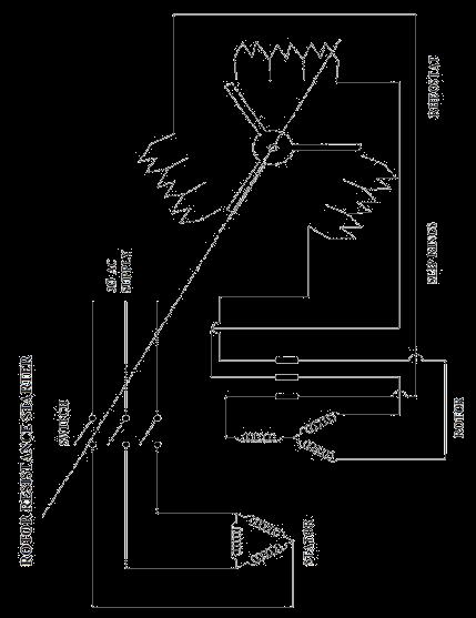
67 Aim: Expt. No. 12 STUDY OF DC AND INDUCTION MOTOR STARTERS To study the different kinds of DC and induction motor starters Theory: The value of the armature current in a DC shunt motor is given by Ia= (V Eb)/ Ra Where V = applied voltage. Ra = armature resistance. E b = Back emf. In practice the value of the armature resistance is of the order of one ohm and at the instant of starting the value of the back emf is zero volts. Therefore under starting conditions the value of the armature current is very high. This high inrush current at the time of starting may damage the motor. To protect the motor from such dangerous current the DC Motors are always started using starters. The types of DC motor starters are i) Two point starters ii) Three point starters iii) Four point starters. The functions of the starters are i) It protects from dangerous high speed. ii) It protects the motor from overloads. i) Two pointstarters: It is used for starting DC series motors which has the problem of over speeding due to the loss of load from its shaft. Here for starting the motor the control arm is moved in clock-wise direction from its OFF position to the ON position against the spring tension. The control arm is held in the ON position by the electromagnet E. The exciting coil of the hold-on electromagnet E is connected in series with the armature circuit. If the motor loses its load, current decreases and hence the strength of the electromagnet also decreases. The control arm returns to the OFF position due to the spring tension, thus preventing the motor from over speeding. The starter also returns to the OFF position when the supply voltage decreases appreciably. L and F are the two points of the starter which are connected with the motor terminals. ii) Three point starter: It is used for starting the shunt or compound motor. The coil of the hold on electromagnet E is connected in series with the shunt field coil. In the case of disconnection in the field circuit the control arm will return to its OFF position due to spring tension. This is necessary because the shunt motor will over speed if it loses excitation. The starter also returns to the OFF position in case of low voltage supply or complete failure of the supply. This protection is therefore is called No Volt Release (NVR). 66 Format No.:DCE/Stud/LM/34/Issue:00/Revision:00
68 Over load protection: When the motor is over loaded it draws a heavy current. This heavy current also flows through the exciting coil of the over load electromagnet (OLR). The electromagnet then pulls an iron piece upwar6.ds which short circuits the coils of the NVR coil. The hold on magnet gets de-energized and therefore the starter arm returns to the OFF position, thus protecting the motor against overload. L, A and F are the three terminals of the three point starter. iii) Four point starter: In a four point starter arm touches the starting resistance, the current from the supply is divided into three paths. One through the starting resistance and the armature, one through the field circuit, and one through the NVR coil. A protective resistance is connected in series with the NVR coil. Since in a four point starter the NVR coil is independent of the of the field circuit connection, the DC motor may over speed if there is a break in the field circuit. A DC motor can be stopped by opening the main switch. The steps of the starting resistance are so designed that the armature current will remain within the certain limits and will not change the torque developed by the motor to a great extent. 67 Format No.:DCE/Stud/LM/34/Issue:00/Revision:00

69 Auto transformer starting: An auto transformer starter consists of an auto transformer and a switch as shown in the figure. When the switch S is put on START position, a reduced voltage is applied across the motor terminals. When the motor picks up speed, say to 80 per cent of its normal speed, the switch is put to RUN position. Then the auto-transformer is cut out of the circuit and full rated voltage gets applied across the motor terminals. The circuit diagram in the figure is for a manual auto-transformer starter. This can be made push button operated automatic controlled starter so that the contacts switch over from start to run position as the motor speed picks up to 80% of its speed. Over-load protection relay has not been shown in the figure. The switch S is air-break type for small motors and oil break type for large motors. Auto transformer may have more than one tapping to enable the user select any suitable starting voltage depending upon the conditions. Series resistors or reactors can be used to cause voltage drop in them and thereby allow low voltage to be applied across the motor terminals at starting. These are cut out of the circuit as the motor picks up speed. 68 Format No.:DCE/Stud/LM/34/Issue:00/Revision:00
70 Star- delta method of starting: The starter phase windings are first connected in star and full voltage is connected across its free terminals. As the motor picks up speed, the windings are disconnected through a switch and they are reconnected in delta across the supply terminals. The current drawn by the motor from the lines is reduced to as compared to the current it would have drawn if connected in delta. The motor windings, first in star and then in delta the line current drawn by the motor at starting is reduced to one third as compared to starting current with the windings delta-connected. In making connections for star-delta starting, care should be taken such that sequence of supply connections to the winding terminals does not change while changing from star connection to delta connection. Otherwise the motor will start rotating in the opposite direction, when connections are changed from star to delta. Star-delta starters are available for manual operation using push button control. An automatic star delta starter used time delay relays (T.D.R) through which star to delta connections take place automatically with some pre-fixed time delay. The delay time of the T.D.R is fixed keeping in view the starting time of the motor. Full voltage or direct on-line starting: When full voltage is connected across the stator terminals of an induction motor, large current is drawn by the windings. This is because, at starting the induction motor behaves as a short circuited transformer with its secondary, i.e. the rotor separated from the primary, i.e. the stator by a small lair-gap. At starting when the rotor is at standstill, emf is induced in the rotor circuit exactly similar to the emf induced in the secondary winding of a transformer. This induced emf of the rotor will circulate a very large current through its windings. The primary will draw very large current from the supply mains to balance the rotor ampere-turns. To limit the stator and rotor currents at starting to a safe value, it may be necessary to reduce the stator supply voltage to a low value. If induction motors are started direct-on-line such a heavy starting current of short duration may not cause harm to the motor since the construction of induction motors are rugged. Other motors and equipment connected to the supply lines will receive reduced voltage. In industrial installations, however, if a number of large motors are started by this method, the voltage drop will be very high and may be really objectionable for the other types of loads connected to the system. The amount of voltage drop will not only be dependent on the size of the motor but also on factors like the capacity of the power supply system, the size and length of the line leading to the motors etc. Indian Electricity Rule restricts direct on line starting of 3 phase induction motors above 5 Hp. Rotor resistance starter: 69 Format No.:DCE/Stud/LM/34/Issue:00/Revision:00

71 In a slip-ring (wound rotor) induction motor, resistance can be inserted in the rotor circuit via slip rings, so as to increase the starting torque. The starting current in the rotor winding is Where Rext= Additional resistance per phase in the rotor circuit. 70 Format No.:DCE/Stud/LM/34/Issue:00/Revision:00
72 71 Format No.:DCE/Stud/LM/34/Issue:00/Revision:00
DHANALAKSHMI COLLEGE OF ENGINEERING Manimangalam, Tambaram, Chennai
 DHANALAKSHMI COLLEGE OF ENGINEERING Manimangalam, Tambaram, Chennai 601 301 DEPARTMENT OF MECHANICAL ENGINEERING EE 8361- Electrical Engineering LABORATORY III SEMESTER - R 2017 LABORATORY MANUAL Name
DHANALAKSHMI COLLEGE OF ENGINEERING MANIMANGALAM. TAMBARAM, CHENNAI B.E. ELECTRICAL AND ELECTRONICS ENGINEERING
 DHANALAKSHMI COLLEGE OF ENGINEERING MANIMANGALAM. TAMBARAM, CHENNAI B.E. ELECTRICAL AND ELECTRONICS ENGINEERING V SEMESTER EE2305 ELECTRICAL MACHINES II LABORATORY LABORATORY MANUAL 1 CONTENT S. No. Name
List of Experiments (Cycle-2)
") List of Experiments (Cycle-) SL.No Experiment HOPKINSON S TEST RETARDATION TEST 3 SEPARATION OF LOSSES IN A SINGLE PHASE TRANSFORMER 4 SEPERATION OF LOSSES IN A DC SHUNT MACHINE 5 SUMPNER S TEST Experiment
List of Experiments (Cycle-) SL.No Experiment HOPKINSON S TEST RETARDATION TEST 3 SEPARATION OF LOSSES IN A SINGLE PHASE TRANSFORMER 4 SEPERATION OF LOSSES IN A DC SHUNT MACHINE 5 SUMPNER S TEST Experiment
ELECTRICAL AND ELECTRONICS LABORATROY MANUAL
 ELECTRICAL AND ELECTRONICS LABORATROY MANUAL K CHAITANYA Assistant Professor Department of Electrical and Electrical Engineering A. NARESH KUMAR Assistant Professor Department of Electrical and Electrical
To expose the students to the operation of D.C. machines and transformers and give them experimental skill.
 TOTAL: 45 PERIODS EE6411 ELECTRICAL MACHINES LABORATORY I L T P C 0 0 3 2 OBJECTIVES: To expose the students to the operation of D.C. machines and transformers and give them experimental skill. LIST OF
VALLIAMMAI ENGINEERING COLLEGE
 VALLIAMMAI ENGINEERING COLLEGE SRM Nagar, Kattankulathur 603 203. DEPARTMENT OF ELECTRICAL AND ELECTRONICS ENGINEERING Question Bank EE6401 ELECTRICAL MACHINES I UNIT I: MAGNETIC CIRCUITS AND MAGNETIC
ELECTRICAL MACHINES-II LABORATORY MANUAL
 ELECTRICAL MACHINES-II LABORATORY MANUAL T. ANIL KUMAR Associate Professor Department of Electrical and Electrical Engineering N. SINDHU Assistant Professor Department of Electrical and Electrical Engineering
EMEC 1 LAB Laboratory Manual
 DEV BHOOMI INSTITUTE OF TECHNOLOGY CHAKRATA ROAD,NAVGAOUN MANDUWALA,UTTARAKHAND Programs: B.TECH. (Electrical and Electronics Engineering) EMEC 1 LAB Laboratory Manual PREPARED BY Saurabh Rajvanshi ASST.PROFESSOR,
EXPERIMENT CALIBRATION OF 1PHASE ENERGY METER
 EXPERIMENT CALIBRATION OF PHASE ENERGY METER THEORY:- Energy Meters are integrating instruments used to measure the quantity of electrical energy supplied to a circuit in a given time. Single phase energy
Regulation: R16 Course & Branch: B.Tech EEE
 SIDDHARTH GROUP OF INSTITUTIONS :: PUTTUR Siddharth Nagar, Narayanavanam Road 517583 QUESTION BANK (Descriptive) Subject with Code : Electrical Machines-II (16EE215) Regulation: R16 Course & Branch: B.Tech
Dev Bhoomi Institute Of Technology LABORATORY Department of Electrical And Electronics Engg. Electro-mechanical Energy Conversion II
 REV. NO. : REV. DATE : PAGE: 1 Electro-mechanical Energy Conversion II 1. To perform no load and blocked rotor tests on a three phase squirrel cage induction motor and determine equivalent circuit. 2.
ELECTRICAL MAINTENANCE
 ELECTRICAL MAINTENANCE II PRACTICAL JOURNAL DATA 1 EXPERIMENT NO. 1 AIM: TO FIND VOLTAGE RATIO OF A GIVEN TRANSFORMER. CIRCUIT DIAGRAM: OBSERVATION TABLE: Sr.No. 1 2 3 4 Primary Voltage (V 1 ) Secondary
ST.ANNE S COLLEGE OF ENGINEERING AND TECHNOLOGY ANGUCHETTYPALAYAM, PANRUTI
 ST.ANNE S COLLEGE OF ENGINEERING AND TECHNOLOGY ANGUCHETTYPALAYAM, PANRUTI 607106. QUESTION BANK DECEMBER 2017 - JUNE 2018 / EVEN SEMESTER BRANCH: EEE YR/SEM: II/IV BATCH: 2016-2020 SUB CODE/NAME: EE6401
2014 ELECTRICAL TECHNOLOGY
 SET - 1 II B. Tech I Semester Regular Examinations, March 2014 ELECTRICAL TECHNOLOGY (Com. to ECE, EIE, BME) Time: 3 hours Max. Marks: 75 Answer any FIVE Questions All Questions carry Equal Marks ~~~~~~~~~~~~~~~~~~~~~~~~~~
Electrical Machines-I (EE-241) For S.E (EE)
 For S.E (EE)") PRACTICAL WORK BOOK For Academic Session 2013 Electrical Machines-I (EE-241) For S.E (EE) Name: Roll Number: Class: Batch: Department : Semester/Term: NED University of Engineer ing & Technology Electrical
PRACTICAL WORK BOOK For Academic Session 2013 Electrical Machines-I (EE-241) For S.E (EE) Name: Roll Number: Class: Batch: Department : Semester/Term: NED University of Engineer ing & Technology Electrical
EE6351 ELECTRIC DRIVES AND CONTROL UNIT-1 INTRODUTION
 EE6351 ELECTRIC DRIVES AND CONTROL UNIT-1 INTRODUTION 1. What is meant by drive and electric drive? Machines employed for motion control are called drives and may employ any one of the prime movers for
UNIT I D.C. MACHINES PART A. 3. What are factors on which hysteresis loss? It depends on magnetic flux density, frequency & volume of the material.
 EE6352-ELECTRICAL ENGINEERING AND INSTRUMENTATION UNIT I D.C. MACHINES PART A 1. What is prime mover? The basic source of mechanical power which drives the armature of the generator is called prime mover.
UNIT - 4 TESTING OF DC MACHINES
 UNIT - 4 TESTING OF DC MACHINES Testing of DC machines can be broadly classified as i) Direct method of Testing ii) Indirect method of testing DIRECT METHOD OF TESTING: In this method, the DC machine is
 EE6401 ELECTRICAL MACHINES I UNIT I: MAGNETIC CIRCUITS AND MAGNETIC MATERIALS PART: A 1. Define EMF and MMF. 2. Name the main magnetic quantities with their symbols having the following units: Webers,
GROUP OF INSTITUTIONS :: PUTTUR UNIT I SINGLE PHASE TRANSFORMERS
 SIDDHARTH GROUP OF INSTITUTIONS :: PUTTUR Siddharth Nagar, Narayanavanam Road 517583 QUESTION BANK (Descriptive) Subject with Code : Electrical Machines-II (16EE215) Course & Branch: B.Tech EEE Regulation:
SYLLABUS. osmania university UNIT - I UNIT - II UNIT - III UNIT - IV CHAPTER - 1 : PRINCIPLES OF ELECTRO-MECHANICAL ENERGY CONVERSION CHAPTER - 2 :
 i UNIT - I SYLLABUS osmania university UNIT - II CHAPTER - 1 : PRINCIPLES OF ELECTRO-MECHANICAL ENERGY CONVERSION Energy in Magnetic System, Field Energy and Mechanical Force, Direction of Mechanical Force
DEPARTMENT OF ELECTRICAL AND ELECTRONICS ENGINEERING
 DEPARTMENT OF ELECTRICAL AND ELECTRONICS ENGINEERING QUESTION BANK 16EET41 SYNCHRONOUS AND INDUCTION MACHINES UNIT I SYNCHRONOUS GENERATOR 1. Why the stator core is laminated? 2. Define voltage regulation
INSTITUTE OF AERONAUTICAL ENGINEERING Dundigal, Hyderabad
 INSTITUTE OF AERONAUTICAL ENGINEERING Dundigal, Hyderabad - 500 043 MECHANICAL ENGINEERING ASSIGNMENT Name : Electrical and Electronics Engineering Code : A40203 Class : II B. Tech I Semester Branch :
DEPARTMENT OF ELECTRICAL & ELECTRONICS ENGINEERING VI SEMESTER (NEW SCHEME)
") DEPARTMENT OF ELECTRICAL & ELECTRONICS ENGINEERING VI SEMESTER (NEW SCHEME) 10EEL67 DC AND SYNCHRONOUS MACHINES LAB LABORATORY MANUAL NAM E OF THE STUDENT : BRANCH : UNIVERSITY SEAT NO. : SEMESTER & SECTION
DEPARTMENT OF ELECTRICAL & ELECTRONICS ENGINEERING VI SEMESTER (NEW SCHEME) 10EEL67 DC AND SYNCHRONOUS MACHINES LAB LABORATORY MANUAL NAM E OF THE STUDENT : BRANCH : UNIVERSITY SEAT NO. : SEMESTER & SECTION
Module 9. DC Machines. Version 2 EE IIT, Kharagpur
 Module 9 DC Machines Lesson 38 D.C Generators Contents 38 D.C Generators (Lesson-38) 4 38.1 Goals of the lesson.. 4 38.2 Generator types & characteristics.... 4 38.2.1 Characteristics of a separately excited
Synchronous Generators I. EE 340 Spring 2011
 Synchronous Generators I EE 340 Spring 2011 Construction of synchronous machines In a synchronous generator, a DC current is applied to the rotor winding producing a rotor magnetic field. The rotor is
EE6401 ELECTRICAL MACHINES I UNIT I: MAGNETIC CIRCUITS AND MAGNETIC MATERIALS PART: A 1. Define EMF and MMF. 2. Name the main magnetic quantities
 EE6401 ELECTRICAL MACHINES I UNIT I: MAGNETIC CIRCUITS AND MAGNETIC MATERIALS PART: A 1. Define EMF and MMF. 2. Name the main magnetic quantities with their symbols having the following units: Webers,
DC CIRCUITS ELECTROMAGNETISM
 DC CIRCUITS 1. State and Explain Ohm s Law. Write in brief about the limitations of Ohm s Law. 2. State and explain Kirchhoff s laws. 3. Write in brief about disadvantages of series circuit and advantages
Synchronous Generators I. Spring 2013
 Synchronous Generators I Spring 2013 Construction of synchronous machines In a synchronous generator, a DC current is applied to the rotor winding producing a rotor magnetic field. The rotor is then turned
 DC MOTORS DC Motors DC Motor is a Machine which converts Electrical energy into Mechanical energy. Dc motors are used in steel plants, paper mills, textile mills, cranes, printing presses, Electrical locomotives
2. Draw the speed-torque characteristics of dc shunt motor and series motor. (May2013) (May 2014)
 (May 2014)") UNIT 2 - DRIVE MOTOR CHARACTERISTICS PART A 1. What is meant by mechanical characteristics? A curve is drawn between speed-torque. This characteristic is called mechanical characteristics. 2. Draw the
UNIT 2 - DRIVE MOTOR CHARACTERISTICS PART A 1. What is meant by mechanical characteristics? A curve is drawn between speed-torque. This characteristic is called mechanical characteristics. 2. Draw the
SRM Institute of Science and Technology (Deemed to be University)
") 5EE0L-ELECTRICAL MACHINES LAB-II RECORD ACADEMIC YEAR: ODD SEMESTER 08-9 NAME : REG.NO. : DEPARTMENT OF ELECTRICAL & ELECTRONICS ENGINEERING FACULTY OF ENGINEERING & TECHNOLOGY SRM Institute of Science
5EE0L-ELECTRICAL MACHINES LAB-II RECORD ACADEMIC YEAR: ODD SEMESTER 08-9 NAME : REG.NO. : DEPARTMENT OF ELECTRICAL & ELECTRONICS ENGINEERING FACULTY OF ENGINEERING & TECHNOLOGY SRM Institute of Science
Principles of Electrical Engineering
 D.C GENERATORS Principle of operation of D.C machines, types of D.C Generators, e.m.f equation of D.C Generator, O.C.C of a D.C Shunt Generator, Load characteristics of D.C.Generators GENERATOR PRINCIPLE:
EE6352-ELECTRICAL ENGINEERING AND INSTRUMENTATION UNIT I D.C. MACHINES PART A
 EE6352-ELECTRICAL ENGINEERING AND INSTRUMENTATION 1. What is prime mover? UNIT I D.C. MACHINES PART A The basic source of mechanical power which drives the armature of the generator is called prime mover.
ELECTRICAL MACHINES I
 PRACTICAL WORK BOOK ELECTRICAL MACHINES I EX-404 Name: Enrollment No: Branch: Semester: Batch: Department of Electrical Engineering Name of Laboratory : Electrical Machine - I Lab Subject Code : Ex 404
SIDDHARTH GROUP OF INSTITUTIONS :: PUTTUR
 SIDDHARTH GROUP OF INSTITUTIONS :: PUTTUR Siddharth Nagar, Narayanavanam Road 517583 QUESTION BANK (DESCRIPTIVE) Subject with Code : ET(16EE212) Year & Sem: II-B.Tech & II-Sem UNIT I DC GENERATORS Course
MUFFAKHAM JAH COLLEGE OF ENGINEERING & TECHNOLOGY EXPT.1: SCOTT CONNECTION OF TRANSFORMERS
 EXPT.1: SCOTT CONNECTION OF TRANSFORMERS Page 1 AIM : To study the conversion of three phase supply to two phase supply by using scott connected transformers NAME PLATE DETAILS: EQUIPMENTS REQUIRED: SL.NO
R07 SET - 1
 R07 SET - 1 II B. Tech II Semester Supplementary Examinations April/May 2013 ELECTRICAL MACHINES - II (Electrical and Electronics Engineering) Time: 3 hours Max. Marks: 80 Answer any FIVE Questions All
Electrical Machines -II
 Objective Type Questions: 1. Basically induction machine was invented by (a) Thomas Alva Edison (b) Fleming (c) Nikola Tesla (d) Michel Faraday Electrical Machines -II 2. What will be the amplitude and
SQA Advanced Unit specification: general information
 SQA Advanced Unit specification: general information Unit title: Electrical Machine Principles Unit code: HT83 47 Superclass: XJ Publication date: August 2017 Source: Scottish Qualifications Authority
EKT112 Principles of Measurement and Instrumentation. Power Measurement
 EKT112 Principles of Measurement and Instrumentation Power Measurement 1 Outline Power? Power in DC and AC Circuits Power Measurements Power Instrumentation (Wattmeter) 2 Concept of Electric POWER Power
Renewable Energy Systems 13
 Renewable Energy Systems 13 Buchla, Kissell, Floyd Chapter Outline Generators 13 Buchla, Kissell, Floyd 13-1 MAGNETISM AND ELECTROMAGNETISM 13-2 DC GENERATORS 13-3 AC SYNCHRONOUS GENERATORS 13-4 AC INDUCTION
Experiment 3. The Direct Current Motor Part II OBJECTIVE. To locate the neutral brush position. To learn the basic motor wiring connections.
 Experiment 3 The Direct Current Motor Part II OBJECTIVE To locate the neutral brush position. To learn the basic motor wiring connections. To observe the operating characteristics of series and shunt connected
DEPARTMENT OF EI ELECTRICAL MACHINE ASSIGNMENT 1
 It is the mark of an educated mind to be able to entertain a thought without accepting it. DEPARTMENT OF EI ELECTRICAL MACHINE ASSIGNMENT 1 1. Explain the Basic concepts of rotating machine. 2. With help
NZQA registered unit standard version 3 Page 1 of 5. Demonstrate and apply knowledge of electrical machines
 Page 1 of 5 Title Demonstrate and apply knowledge of electrical machines Level 5 Credits 15 Purpose This unit standard covers knowledge and the application of d.c. and a.c. electrical machines for engineers.
Operation Construction Classification Applications. DC Motors
 Operation Construction Classification Applications DC Motors A DC Motor converts electrical energy into mechanical energy. Special applications where dc motors are used include: in steel mills, mines
SPEED CONTROL OF DC SHUNT MOTOR
 INDEX NO. : M-140 TECHNICAL MANUAL FOR SPEED CONTROL OF DC SHUNT MOTOR Manufactured by : PREMIER TRADING CORPORATION (An ISO 9001:2000 Certified Company) 212/1, Mansarover Civil Lines, MEERUT. Phone :
APPARATUS AND MATERIAL REQUIRED Resistor, ammeter, (0-1.5A) voltmeter (0-5V ), battery, one way key, rheostat, sand paper, connecting wires.
 voltmeter (0-5V ), battery, one way key, rheostat, sand paper, connecting wires.") ACTIVITIES ACTIVITY 1 AIM To assemble the components of a given electrical circuit. APPARATUS AND MATERIAL REQUIRED Resistor, ammeter, (0-1.5A) voltmeter (0-5V ), battery, one way key, rheostat, sand paper,
ACTIVITIES ACTIVITY 1 AIM To assemble the components of a given electrical circuit. APPARATUS AND MATERIAL REQUIRED Resistor, ammeter, (0-1.5A) voltmeter (0-5V ), battery, one way key, rheostat, sand paper,
(d) None of the above.
 None of the above.") Dr. Mahalingam College of Engineering and Technology, Pollachi-3 (An Autonomous Institution affiliated to Anna niversity) CCET II (2016 Regulation) Name of Programme: B.E. (EEE) Course Code & Course Title:
Dr. Mahalingam College of Engineering and Technology, Pollachi-3 (An Autonomous Institution affiliated to Anna niversity) CCET II (2016 Regulation) Name of Programme: B.E. (EEE) Course Code & Course Title:
2 Principles of d.c. machines
 2 Principles of d.c. machines D.C. machines are the electro mechanical energy converters which work from a d.c. source and generate mechanical power or convert mechanical power into a d.c. power. These
CHAPTER THREE DC MOTOR OVERVIEW AND MATHEMATICAL MODEL
 CHAPTER THREE DC MOTOR OVERVIEW AND MATHEMATICAL MODEL 3.1 Introduction Almost every mechanical movement that we see around us is accomplished by an electric motor. Electric machines are a means of converting
2-marks question bank UNIT I - TRANSFORMERS UNIT II: AC MACHINES
 2-marks question bank UNIT I - TRANSFORMERS 1. What is all day efficiency? 2. What are the applications of auto transformers? 3. Why transformer rating is expressed in KVA? 4. Does transformer draw any
GUJARAT TECHNOLOGICAL UNIVERSITY, AHMEDABAD, GUJARAT. Course Curriculum. D C MACHINES AND TRANSFORMERS (Code: ) Electrical Engineering
 Electrical Engineering") GUJARAT TECHNOLOGICAL UNIVERSITY, AHMEDABAD, GUJARAT Course Curriculum D C MACHINES AND TRANSFORMERS (Code: 3330902) Diploma Programme in which this course is offered Semester in which offered Electrical
GUJARAT TECHNOLOGICAL UNIVERSITY, AHMEDABAD, GUJARAT Course Curriculum D C MACHINES AND TRANSFORMERS (Code: 3330902) Diploma Programme in which this course is offered Semester in which offered Electrical
ROEVER COLLEGE OF ENGINEERING & TECHNOLOGY Elambalur- Perambalur DEPARTMENT OF ELECTRICAL AND ELECTRONICS ENGINEERING
 ROEER COLLEGE OF ENGINEERING & TECHNOLOGY Elambalur- Perambalur-621212 DEPRTMENT OF ELECTRICL ND ELECTRONIC ENGINEERING ELECTRICL MCHINE LBORTORY 1 Laboratory Observation Book ersion - 01 Name: Register
Single Phase Induction Motor. Dr. Sanjay Jain Department Of EE/EX
 Single Phase Induction Motor Dr. Sanjay Jain Department Of EE/EX Application :- The single-phase induction machine is the most frequently used motor for refrigerators, washing machines, clocks, drills,
1. This question is about electrical energy and associated phenomena.
 1. This question is about electrical energy and associated phenomena. Electromagnetism The current in the circuit is switched on. electromagnet State Faraday s law of electromagnetic induction and use
Electrical Machines I Week 1: Overview, Construction and EMF equation
 Electrical Machines I Week 1: Overview, Construction and EMF equation Course Contents Definition of the magnetic terms, magnetic materials and the B-H curve. Magnetic circuits principles. Electromechanical
AE105 PRINCIPLES OF ELECTRICAL ENGINEERING JUNE 2014
 Q.2 a. Explain in detail eddy current losses in a magnetic material. Explain the factors on which it depends. How it can be reduced? IETE 1 b. A magnetic circuit with a single air gap is shown in given
DHANALAKSHMI SRINIVASAN COLLEGE OF ENGINEERING AND TECHNOLOGY MAMALLAPURAM, CHENNAI
 DHANALAKSHMI SRINIVASAN COLLEGE OF ENGINEERING AND TECHNOLOGY MAMALLAPURAM, CHENNAI -603104 DEPARTMENT OF ELECTRICAL AND ELECTRONICS ENGINEERING QUESTION BANK VII SEMESTER EE6501-Power system Analysis
Unit III-Three Phase Induction Motor:
 INTRODUCTION Unit III-Three Phase Induction Motor: The three phase induction motor runs on three phase AC supply. It is an ac motor. The power is transferred by means of induction. So it is also called
Syllabus for the Trade of Electrician Duration : Six Month Second Semester Semester Code: ELE: SEM II
 Syllabus for the Trade of Electrician Duration : Six Month Second Semester Semester Code: ELE: SEM II Week Trade practical No. 1-2 Different wave shapes of rectifiers and their values using C.R.O. Identification
The Wound-Rotor Induction Motor Part I
 Experiment 1 The Wound-Rotor Induction Motor Part I OBJECTIVE To examine the construction of the three-phase wound-rotor induction motor. To understand exciting current, synchronous speed and slip in a
II/IV B.Tech(Regular) DEGREE EXAMINATION. Electronics & Instrumentation Engineering
 DEGREE EXAMINATION. Electronics & Instrumentation Engineering") SCHME OF EVALUTION II/IV B.Tech(Regular) DEGREE EXAMINATION JUNE,2016 EI ET 403 Electrical Technology Electronics & Instrumentation Engineering Max.Marks :60 marks -----------------------------------------------------------------------------------------------------------
SCHME OF EVALUTION II/IV B.Tech(Regular) DEGREE EXAMINATION JUNE,2016 EI ET 403 Electrical Technology Electronics & Instrumentation Engineering Max.Marks :60 marks -----------------------------------------------------------------------------------------------------------
GUJARAT TECHNOLOGICAL UNIVERSITY, AHMEDABAD, GUJARAT COURSE CURRICULUM. Course Title: D C MACHINES AND TRANSFORMER (Code: )
") GUJARAT TECHNOLOGICAL UNIVERSITY, AHMEDABAD, GUJARAT COURSE CURRICULUM Course Title: D C MACHINES AND TRANSFORMER (Code: 3330902) Diploma Programme in which this course is offered Electrical Engineering
GUJARAT TECHNOLOGICAL UNIVERSITY, AHMEDABAD, GUJARAT COURSE CURRICULUM Course Title: D C MACHINES AND TRANSFORMER (Code: 3330902) Diploma Programme in which this course is offered Electrical Engineering
St.MARTIN S ENGINEERING COLLEGE Dhulapally, Secunderabad
 St.MARTIN S ENGINEERING COLLEGE Dhulapally, Secunderabad-500 014 Subject: STATIC DRIVES Class : EEE III TUTORIAL QUESTION BANK Group I QUESTION BANK ON SHORT ANSWER QUESTION UNIT-I 1 What is meant by electrical
 VALLIAMMAI ENGINEERING COLLEGE MECHANICAL ENGINEERING ANNA UNIVERSITY CHENNAI II YEAR MECH / III SEMESTER EE6351 - ELECTRICAL DRIVES AND CONTROL (REGULATION 2013) UNIT I INTRODUCTION PART-A (2 MARKS) 1.
TWO MARK QUESTIONS-ANSWERS
 TWO MARK QUESTIONS-ANSWERS DEPARTMENT: MECH SEMESTER : III SUBJECT CODE: ME2205 SUBJECT NAME: ELECTRIC DRIVES & CONTROL 1. Define Drive and Electric Drive. Drive: A particular system employed for motion
UNIT 2. INTRODUCTION TO DC GENERATOR (Part 1) OBJECTIVES. General Objective
 OBJECTIVES. General Objective") DC GENERATOR (Part 1) E2063/ Unit 2/ 1 UNIT 2 INTRODUCTION TO DC GENERATOR (Part 1) OBJECTIVES General Objective : To apply the basic principle of DC generator, construction principle and types of DC generator.
DC GENERATOR (Part 1) E2063/ Unit 2/ 1 UNIT 2 INTRODUCTION TO DC GENERATOR (Part 1) OBJECTIVES General Objective : To apply the basic principle of DC generator, construction principle and types of DC generator.
1. Magnetization Characteristics of DC Shunt Generator
 im: 1. Magnetization Characteristics of DC Shunt Generator To conduct an experiment on a D.C shunt generator and draw the magnetization characteristics (OCC) and to determine the critical field resistance
DHANALAKSHMI COLLEGE OF ENGINEERING DEPARTMENT OF MECHANICAL ENGINEERING ME 6351 ELECTRICAL DRIVES AND CONTROL UNIVERSITY QUESTIONS AND ANSWERS
 DHANALAKSHMI COLLEGE OF ENGINEERING DEPARTMENT OF MECHANICAL ENGINEERING ME 6351 ELECTRICAL DRIVES AND CONTROL UNIVERSITY QUESTIONS AND ANSWERS 1) What is the Necessity of starter? UNIT 3 Two Marks Both
Scheme - I. Sample Question Paper
 Program Name Program Code Course Title Sample Question Paper : Diploma in Industrial Electronics : IE : Electrical Machines and Transformers Max. Marks : 70 Time : 3 Hrs. Q1. ATTEMPT ANY FIVE OF THE FOLLOWING.
PHYSICS MCQ (TERM-1) BOARD PAPERS
 BOARD PAPERS") GRADE: 10 PHYSICS MCQ (TERM-1) BOARD PAPERS 1 The number of division in ammeter of range 2A is 10 and voltmeter of range 5 V is 20. When the switch of the circuit given below is closed, ammeter reading
GRADE: 10 PHYSICS MCQ (TERM-1) BOARD PAPERS 1 The number of division in ammeter of range 2A is 10 and voltmeter of range 5 V is 20. When the switch of the circuit given below is closed, ammeter reading
INTRODUCTION Principle
 DC Generators INTRODUCTION A generator is a machine that converts mechanical energy into electrical energy by using the principle of magnetic induction. Principle Whenever a conductor is moved within a
SSC-JE STAFF SELECTION COMMISSION ELECTRICAL ENGINEERING STUDY MATERIAL ELECTRICAL MACHINES
 1 SSC-JE STAFF SELECTION COMMISSION ELECTRICAL ENGINEERING STUDY MATERIAL 28-B/7, Jia Sarai, Near IIT, Hauz Khas, New Delhi-110016. Ph. 011-26514888. www.engineersinstitute.com 2 CONTENT 1. : DC MACHINE,
CHAPTER 6 DESIGN AND DEVELOPMENT OF DOUBLE WINDING INDUCTION GENERATOR
 100 CHAPTER 6 DESIGN AND DEVELOPMENT OF DOUBLE WINDING INDUCTION GENERATOR 6.1 INTRODUCTION Conventional energy resources are not sufficient to meet the increasing electrical power demand. The usages of
Pretest Module 21 Unit 4 Single-Phase Motors
 Pretest Module 21 Unit 4 Single-Phase Motors 1. What are the four main components of a single-phase motor? Rotor, stator, centrifugal switch, end bells and bearings 2. How is a rotating field created in
Contents. Review of Electric Circuitd. Preface ;
 Preface ; Chapter 1 Review of Electric Circuitd 1.1 Introduction, 1 1.2 Direct Circuit Current, 1 1.2.1 Voltage, 3 1.2.2 Power, 3 1.2.3 Ohm's Law, 5 1.2.4 KirchhofTs Laws, 5 1.2.4.1 Kirchhoff s Current
AC : USING MATLAB TO TEACH ELECTRIC ENERGY COURSES
 AC 2012-3239: USING MATLAB TO TEACH ELECTRIC ENERGY COURSES Dr. Max Rabiee P.E., University of Cincinnati Max Rabiee earned his Ph.D. in electrical engineering from the University of Kentucky (U.K.) in
SIDDHARTH GROUP OF INSTITUTIONS :: PUTTUR
 SIDDHARTH GROUP OF INSTITUTIONS :: PUTTUR Siddharth Nagar, Narayanavanam Road 517583 QUESTION BANK (DESCRIPTIVE) Subject with Code : EMT(15A01301) Year & Sem: II-B.Tech & I-Sem Course & Branch: B.Tech-CE
EXPERIMENT 19. Starting and Synchronizing Synchronous Machines PURPOSE: BRIEFING: To discover the method of starting synchronous motors.
 EXPERIMENT 19 Starting and Synchronizing Synchronous Machines PURPOSE: To discover the method of starting synchronous motors. BRIEFING: When three-phase is applied to the stator of a three-phase motor,
INDUCTANCE FM CHAPTER 6
 CHAPTER 6 INDUCTANCE INTRODUCTION The study of inductance is a very challenging but rewarding segment of electricity. It is challenging because at first it seems that new concepts are being introduced.
Academic Course Description
 BEE305- ELECTRICAL MACHINES Academic Course Description BHARATH UNIVERSITY Faculty of Engineering and Technology Department of Electrical and Electronics Engineering BEE305- ELECTRICAL MACHINES Third Semester,
Sharjah Indian School Sharjah Boys Wing
 Read the instructions given below carefully before writing the fair record book. The following details are to be written on the LEFT HAND SIDE of the book. CIRCUIT DIAGRAM CALCULATIONS The remaining details
VISION OF INSTITUTION MISSION OF INSTITUTION
 JEPPIAAR ENGINEERING COLLEGE DEPARTMENT OF ELECTRICAL AND ELECTRONICS ENGINEERING EE8353-ELECTRICAL DRIVES AND CONTROLS The Question bank contains the Following: Vision and mission of college and dept
Study and Measure the Active and Reactive Power Developed By a Three Phase Induction Generator with Capacitive Load
 International Journal of Engineering and Technical Research (IJETR) Study and Measure the Active and Reactive Power Developed By a Three Phase Induction Generator with Capacitive Load Surajit Mondal, Oisik
Federal Urdu University of Arts, Science & Technology Islamabad Pakistan ELECTRICAL MACHINES
 ELECTRICAL MACHINES CONTROL SYSTEMS & MACHINES LAB DEPARTMENT OF ELECTRICAL ENGINEERING Prepared By: Checked By: Approved By: Engr. Yousaf Hameed Engr. M.Nasim Khan Dr.Noman Jafri Lecturer (Lab) Electrical,
Part- A Objective Questions (10X1=10 Marks)
") Dr. Mahalingam College of Engineering and Technology, Pollachi-3 (An Autonomous Institution) CCET 3(2016Regulation) Name of Programme: B.E. (EEE) Course Code&Course Title: 16EET41 & Synchronous & Induction
Dr. Mahalingam College of Engineering and Technology, Pollachi-3 (An Autonomous Institution) CCET 3(2016Regulation) Name of Programme: B.E. (EEE) Course Code&Course Title: 16EET41 & Synchronous & Induction
Pretest Module 21 Units 1-4 AC Generators & Three-Phase Motors
 Pretest Module 21 Units 1-4 AC Generators & Three-Phase Motors 1. What are the two main parts of a three-phase motor? Stator and Rotor 2. Which part of a three-phase squirrel-cage induction motor is a
TESTING OF D.C. MACHINES
 CONTENTS C H A P T E R 31 Learning Objectives Brake Test Swinburne s Test Advantages of Swinburne s Test Main Disadvantages Regenerative or Hopkinson s Test Alternative Connections for Hopkinson s Test
To discover the factors affecting the direction of rotation and speed of three-phase motors.
 EXPERIMENT 12 Direction of Rotation of Three-Phase Motor PURPOSE: To discover the factors affecting the direction of rotation and speed of three-phase motors. BRIEFING: The stators of three-phase motors
694 Electric Machines
 694 Electric Machines 9.1 A 4-pole wound-rotor induction motor is used as a frequency changer. The stator is connected to a 50 Hz, 3-phase supply. The load is connected to the rotor slip rings. What are
Institute of Technology, Nirma University B. Tech. Sem. V: Electrical Engineering 2EE305: ELECTRICAL MACHINES II. Handout: AC Commutator Motors
 Institute of Technology, Nirma University B. Tech. Sem. V: Electrical Engineering 2EE305: ELECTRICAL MACHINES II Handout: AC Commutator Motors Prepared by: Prof. T. H. Panchal Learning Objective: Introduction
Scope for Electrical Machine Design. Objectives. Design and Engineering. Course Description. 23-Dec-16 DESIGN OF ELECTRICAL MACHINES AN OVERVIEW
 SNS COLLEGE OF ENGINEERING (Accredited by NAAC-UGC with A Grade, Approved by AICTE, Recognized by UGC and Affiliated to Anna University, Chennai) COIMBATORE 641 107 DEPARTMENT OF ELECTRICAL AND ELECTRONICS
Historical Development
 TOPIC 3 DC MACHINES DC Machines 2 Historical Development Direct current (DC) motor is one of the first machines devised to convert electrical power into mechanical power. Its origin can be traced to the
ELECTRICITY: INDUCTORS QUESTIONS
 ELECTRICITY: INDUCTORS QUESTIONS No Brain Too Small PHYSICS QUESTION TWO (2017;2) In a car engine, an induction coil is used to produce a very high voltage spark. An induction coil acts in a similar way
CURRENT ELECTRICITY - II
 SALIENT FEATURES Faraday s laws of electrolysis Magnetic effects of electricity Electro magnetic induction CURRENT ELECTRICITY - II FARADAY S LAWS OF ELECTROYLYSIS ELECTROLYSIS The process of decomposition
EEE3441 Electrical Machines Department of Electrical Engineering. Lecture. Introduction to Electrical Machines
 Department of Electrical Engineering Lecture Introduction to Electrical Machines 1 In this Lecture Induction motors and synchronous machines are introduced Production of rotating magnetic field Three-phase
PHY 152 (ELECTRICITY AND MAGNETISM)
") PHY 152 (ELECTRICITY AND MAGNETISM) ELECTRIC MOTORS (AC & DC) ELECTRIC GENERATORS (AC & DC) AIMS Students should be able to Describe the principle of magnetic induction as it applies to DC and AC generators.
PHY 152 (ELECTRICITY AND MAGNETISM) ELECTRIC MOTORS (AC & DC) ELECTRIC GENERATORS (AC & DC) AIMS Students should be able to Describe the principle of magnetic induction as it applies to DC and AC generators.
Brake Test On Three Phase Induction Motor Lab Manual
 Brake Test On Three Phase Induction Motor Lab Manual Electrical engineering machine lab manual. Brake test on three phase squirrel cage induction motor. No-load &, blocked rotor tests on three phase Slip.
R13 SET - 1. b) Describe different braking methods employed for electrical motors. [8M]
![R13 SET - 1. b) Describe different braking methods employed for electrical motors. [8M]](/thumbs/89/100786446.jpg "R13 SET - 1. b) Describe different braking methods employed for electrical motors. [8M]") Code No:RT32026 R13 SET - 1 III B. Tech II Semester Regular Examinations, April - 2016 POWER SEMICONDUCTOR DRIVES (Electrical and Electronics Engineering) Time: 3 hours Maximum Marks: 70 Note: 1. Question
Code No:RT32026 R13 SET - 1 III B. Tech II Semester Regular Examinations, April - 2016 POWER SEMICONDUCTOR DRIVES (Electrical and Electronics Engineering) Time: 3 hours Maximum Marks: 70 Note: 1. Question