DRY BULK MATERIAL HANDLING COMPONENTS. AFTER-MARKET SPARE PARTS. PNEUMATIC CONVEYING EQUIPMENT. PNEUMATIC CONVEYING COMPONENTS & SPARE PARTS
|
|
|
- Philomena Perry
- 5 years ago
- Views:
Transcription


1 DRY BULK MATERIAL HANDLING COMPONENTS. AFTER-MARKET SPARE PARTS. PNEUMATIC CONVEYING EQUIPMENT. PNEUMATIC CONVEYING COMPONENTS & SPARE PARTS


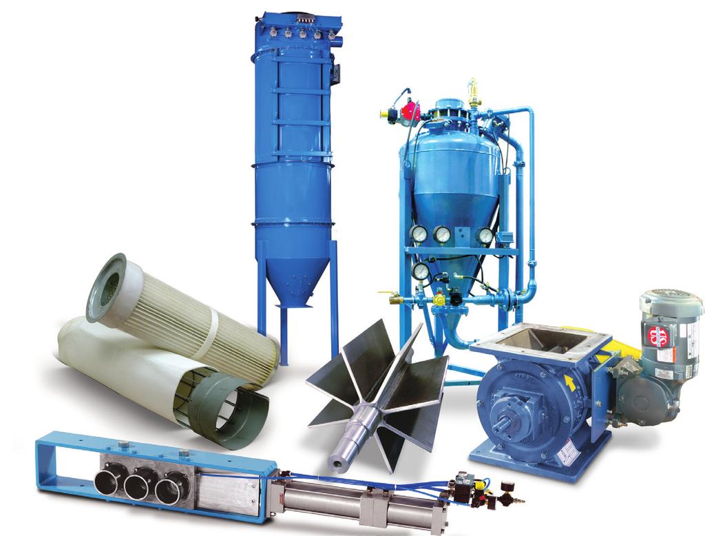
2 PNEUMATIC COMPONENTS AIRLOCKS, PARTS & ACCESSORIES Searching for the right solution? Magnum Systems offers a complete line of pneumatic conveying components and spare parts. Our customer service professionals have an average of 10 years in industry application experience, each with the knowledge and expertise necessary to bring top-flight service for an incredible range of products. Rotary Airlock Valves Available in various sizes and materials with replacement parts Bin Vents, Filter Receivers, Silos and Accessories Complete assemblies and parts Blowers and Fans Complete assemblies as well as replacement units Rail Car Accessories Airlift and manual discharge adapters Diverters Pneumatic or gravity applications Valves Knife gates, slide gates, ball valves and butterfly valves Engineering, Design & Manufacturing to Keep the Line Moving

3 SECTION 1 ROTARY VALVES TABLE OF CONTENTS SECTION 1 Rotary Valves ROTARY VALVES Type 1 Square flange S1-1 Round flange S1-3 Type 2 Square flange S1-5 Round flange S1-7 Type 3 Square flange S1-9 Round flange S1-11 Type 4 Square flange S1-13 Type 5 Square flange S1-15 Type 6 Square flange S1-17 DC Series Square/round flange S1-19 WFI 394 Square flange S1-21 Rotary Valve Accessories Vented Inlet Adapter S1-23 Rotary Valve Flat Plate Adapter S1-24 Non-adjustable Flow Pellet Valve S1-25 Discharge Adapter S1-26 Maintenance Flange (Gate) S1-27 Discharge Transitions S1-28 Rotary Valve Feeder Inlet Hopper S1-29 Shaft Air Purge S1-30 Low Pressure Cavity Air Purge S1-31 SECTION 1 ROTARY VALVES SAFETY NOTICE Design Engineers Technicians Installers SAFETY NOTICE The inlet and outlet of the rotary valve must have proper attachments to prevent anyone from being able to insert their hands, or foreign objects, into the valve when in operation. S1-0

4 SECTION 1 ROTARY VALVES Type 1, Square Flange PRODUCT DESCRIPTION The Smoot Type 1 is a basic, yet versatile rotary valve. With a wide range of options and accessories, the Type 1 will operate efficiently in your system. Constructed with cast iron housing and end plates Open end rotor constructed of A-36 carbon steel Outboard bearings with three molyurethane U-cup packing rings per side Chain and sprocket drive with guard Suitable for conveying most products OPTIONS Relieved tips and vane edge rotors High temperature modifications Shaft air purge Replaceable tips abrasion resistant carbon steel or urethane flex-tip Reduced capacity rotors Zero speed switches Sand blast preparation and custom paint Motor mounting brackets Telfon and chrome coatings available SAFETY NOTICE Design Engineers Technicians Installers SAFETY NOTICE The inlet and outlet of the rotary valve must have proper attachments to prevent anyone from being able to insert their hands, or foreign objects, into the valve when in operation. S1-1
5 SECTION 1 ROTARY VALVES Type 1, Square Flange L G 1.25 in ±0.50 in (31.75 mm ±12.70 mm) (FT7-FT22) 2.00 in ±0.50 in (50.80 mm ±12.70 mm) (FT30) FOR CHAIN ADJUSTMENT H (TYPICAL) V 1.0 in (25.4 mm) J (SQUARE) ROTOR ROTATION P Ø DD (OUTSIDE) CC AA E (SQUARE) A W K Q M OSHA GUARD N AIR INLET U (3) HOLES MOTOR SIDE ONLY Y BB STRAIGHT THROUGH DISCHARGE ADAPTER OSHA GUARD in (11.11 mm) DRILL (FT7-FT22) in (14.29 mm) DRILL (FT30) T HOLES EACH FLANGE AIR BLAST DISCHARGE ADAPTER TOP AND BOTTOM FLANGE THE SAME CC B (TYPICAL) EE I (TYPICAL) in (9.53 mm) 16 NC (FT9-FT22) in (12.70 mm) 13 NC (FT30) S TAPPED HOLES EACH FLANGE C F (SQUARE) C D D DRIVE END HAS R KEYWAY THIS END NOT KEYED NOTE: CENTER MOTOR MOUNTING HOLE IS NOT ALWAYS IN CENTER OF CYLINDER HOUSING (FT7, FT11, FT14, FT18) SEE DIMENSION Q FOR OFFSET DISTANCE Feeder Dimensions (Type 1) Feeder Dimensions (Type 1) FT7 FT9 FT11 FT12 FT14 FT16 FT18 FT22 A 4-1/4 4-3/4 5-7/8 6-1/2 7-3/ /4 B 1-3/4 1-3/ /4 2-1/4 2-1/2 3-1/4 3-3/4 C 4-3/4 5-1/4 5-3/4 6-1/2 5-1/4 5-1/2 6 5 D 3/4 3/4 3/4 1 5/8 3/4 1 1 E F G 18-3/4 21-3/8 24-9/ / / /4 39-5/8 39-7/8 H 9-3/ / /8 14-1/ /8 16-5/8 19-3/ /16 I /4 1-1/2 1-3/4 1-3/4 2-7/16 2-7/16 FT7 FT9 FT11 FT12 FT14 FT16 FT18 FT22 P 5-3/8 6-1/4 7-1/4 7-1/2 8-7/8 10-1/8 11-9/ /4 Q 1-1/ / /16 0 5/16 0 R 1/8x1/4 1/8x1/4 1/8x1/4 1/8x1/4 3/16x3/8 3/16x3/8 5/16x5/8 5/16x5/8 S T U 3/8-16 3/8-16 3/8-16 3/8-16 1/2-13 1/2-13 1/2-13 1/2-13 Y 3/8 9/16 9/16 9/16 3/4 3/4 3/4 3/4 Net Cubic Feet Dispersed Per Revolution FT7 FT9 FT11 FT12 FT14 FT16 FT18 FT22 J /4 1-1/4 1-1/4 1-1/2 1-1/2 1-1/2 K 2-1/4 2-1/ /8 5-3/8 6 6 L 4 4-1/4 6-1/4 6-1/ /8 10-1/8 M 9-7/8 12-1/2 14-5/8 15-3/4 17-5/8 19-5/8 21-3/4 25-7/8 N 9-7/8 4-15/16 7-5/16 7-7/8 8-13/ / / /16 Open End Rotor Shipping Weight With Motor (lbs.) FT7 FT9 FT11 FT12 FT14 FT16 FT18 FT For Electric Motor Dimensions, contact The Service Center. SAFETY NOTICE Design Engineers Technicians Installers SAFETY NOTICE The inlet and outlet of the rotary valve must have proper attachments to prevent anyone from being able to insert their hands, or foreign objects, into the valve when in operation. S1-2

6 SECTION 1 ROTARY VALVES Type 1, Round Flange PRODUCT DESCRIPTION The Smoot Type 1 is a basic, yet versatile rotary valve. With a wide range of options and accessories, and multiple sizes in stock, the Type 1 will operate efficiently in your system. Constructed with cast iron housing and end plates Open end rotor constructed of A-36 carbon steel Outboard bearings with three molyurethane U-cup packing rings per side Chain and sprocket drive with guard Suitable for conveying most products OPTIONS Relieved tips and vane edge rotors High temperature modifications Shaft air purge Replaceable tips abrasion resistant carbon steel or urethane Reduced capacity rotors Zero speed switches Sand blast preparation and custom paint Motor mounting brackets Telfon and chrome coatings available SAFETY NOTICE Design Engineers Technicians Installers SAFETY NOTICE The inlet and outlet of the rotary valve must have proper attachments to prevent anyone from being able to insert their hands, or foreign objects, into the valve when in operation. S1-3
7 SECTION 1 ROTARY VALVES Type 1, Round Flange L G 1.25 in ±0.50 in (31.75 mm ±12.70 mm) FOR CHAIN ADJUSTMENT W H (TYPICAL) 1.0 in (25.4 mm) J (SQUARE) ROTOR ROTATION P X Ø DD (OUTSIDE) CC AA A K Q M OSHA GUARD N U (3) HOLES MOTOR SIDE ONLY D AIR INLET BB OSHA GUARD Ø S T HOLES EACH FLANGE EQUALLY SPACED ON A C DBC TOP AND BOTTOM FLANGE THE SAME B (TYPICAL) I (TYPICAL) 0.50 in (12.70 mm) 13 TAP V TAPPED HOLES EACH FLANGE Ø E (INSIDE) Ø F (OUTSIDE) DRIVE END HAS R KEYWAY THIS END NOT KEYED Feeder Dimensions (Round Flange) Feeder Dimensions (Round Flange) FTP9 FTP12 FTP9 FTP12 A 5-3/4 7-3/4 B 1-3/4 2-1/4 C 11-3/4 14-1/4 D 5/8 5/8 E 8 10 F 13-1/2 16 G 21-3/8 28-1/8 H 10-11/ /16 P 6-1/4 7-1/2 Q 0 0 R 1/8x1/4 1/8x1/4 S 9/16 9/16 T 8 8 U 3/8-16 3/8-16 V 0 4 Net Cu. Ft. Dispersed Per Revolution I 1 1-1/2 FTP9 FTP12 J 1 1-1/4 K 2-1/2 4 Open End Rotor L 4-1/4 6-1/4 Shipping Weight With Motor (lbs.) M 12-7/8 15-7/8 FTP9 FTP12 N 6-7/ / For Electric Motor Dimensions, contact The Service Center. SAFETY NOTICE Design Engineers Technicians Installers SAFETY NOTICE The inlet and outlet of the rotary valve must have proper attachments to prevent anyone from being able to insert their hands, or foreign objects, into the valve when in operation. S1-4

8 SECTION 1 ROTARY VALVES Type 2, Square Flange PRODUCT DESCRIPTION The Smoot Type 2 rotary valve is designed to handle moderately abrasive materials. The Type 2 is constructed with a cast-iron housing with hard chrome plating on the interior machined surfaces to provide a long lasting, economical rotary valve. Abrasion-resistant Constructed of cast iron housing with hard chrome plated on interior machined surfaces Closed end carbon steel rotor with replaceable hardened steel tips Includes HiPres Shaft Air Purge assembly, including filter, regulator, pressure gauge, NEMA 4 solenoid, hose and fittings OPTIONS Relieved tips and rotor shrouds High temperature modifications Reduced capacity rotors Low pressure cavity air purge Zero speed switches Sand blast preparation and custom paint Motor mounting brackets Telfon coated rotors available SAFETY NOTICE Design Engineers Technicians Installers SAFETY NOTICE The inlet and outlet of the rotary valve must have proper attachments to prevent anyone from being able to insert their hands, or foreign objects, into the valve when in operation. S1-5
9 SECTION 1 ROTARY VALVES Type 2, Square Flange L G 1.25 in ±0.50 in (31.75 mm ±12.70 mm) (FT7-FT22) 2.00 in ±0.50 in (50.80 mm ±12.70 mm) (FT30) FOR CHAIN ADJUSTMENT H (TYPICAL) V 1.0 in (25.4 mm) J (SQUARE) ROTOR ROTATION P Ø DD (OUTSIDE) CC AA E (SQUARE) A W K Q M OSHA GUARD N AIR INLET U (3) HOLES MOTOR SIDE ONLY Y BB STRAIGHT THROUGH DISCHARGE ADAPTER OSHA GUARD in (11.11 mm) DRILL (FT7-FT22) in (14.29 mm) DRILL (FT30) T HOLES EACH FLANGE AIR BLAST DISCHARGE ADAPTER TOP AND BOTTOM FLANGE THE SAME CC B (TYPICAL) EE I (TYPICAL) in (9.53 mm) 16 NC (FT9-FT22) in (12.70 mm) 13 NC (FT30) S TAPPED HOLES EACH FLANGE C F (SQUARE) C D D DRIVE END HAS R KEYWAY THIS END NOT KEYED NOTE: CENTER MOTOR MOUNTING HOLE IS NOT ALWAYS IN CENTER OF CYLINDER HOUSING (FT7, FT11, FT14, FT18) SEE DIMENSION Q FOR OFFSET DISTANCE Feeder Dimensions (Type 2) Feeder Dimensions (Type 2) FT9 FT11 FT12 FT14 FT16 FT18 FT22 FT30 A 4-3/4 5-7/8 6-1/2 7-3/ /4 16-3/16 B 1-3/ /4 2-1/4 2-1/2 3-1/4 3-3/4 2-5/8 C 5-1/4 5-3/4 6-1/2 5-1/4 5-1/ D 3/4 3/4 1 5/8 3/ /2 E F G 21-3/8 24-9/ / / /4 39-5/8 39-7/8 50-3/4 H 10-11/ /8 14-1/ /8 16-5/8 19-3/ / /8 I 1 1-1/4 1-1/2 1-3/4 1-3/4 2-7/16 2-7/16 3-3/8 FT9 FT11 FT12 FT14 FT16 FT18 FT22 FT30 P 6-1/4 7-1/4 7-1/2 8-7/8 10-1/8 11-9/ /4 17-1/2 Q 0 1-3/ /16 0 5/ R 1/8x1/4 1/8x1/4 1/8x1/4 3/16x3/8 3/16x3/8 5/16x5/8 5/16x5/8 7/16x7/8 S T U 3/8-16 3/8-16 3/8-16 1/2-13 1/2-13 1/2-13 1/2-13 5/8-11 Y 9/16 9/16 9/16 3/4 3/4 3/4 3/4 1 Net Cubic Feet Dispersed Per Revolution FT9 FT11 FT12 FT14 FT16 FT18 FT22 FT30* J 1 1-1/4 1-1/4 1-1/4 1-1/2 1-1/2 1-1/2 1-3/4 K 2-1/ /8 5-3/ L 4-1/4 6-1/4 6-1/ /8 10-1/8 12-1/4 M 12-1/2 14-5/8 15-3/4 17-5/8 19-5/8 21-3/4 25-7/8 37 N 4-15/16 7-5/16 7-7/8 8-13/ / / / /2 Closed End Rotor Shipping Weight With Motor (lbs.) FT9 FT11 FT12 FT14 FT16 FT18 FT22 FT30* For Electric Motor Dimensions, contact The Service Center. SAFETY NOTICE Design Engineers Technicians Installers SAFETY NOTICE The inlet and outlet of the rotary valve must have proper attachments to prevent anyone from being able to insert their hands, or foreign objects, into the valve when in operation. S1-6

10 SECTION 1 ROTARY VALVES Type 2, Round Flange PRODUCT DESCRIPTION The Smoot Type 2 rotary valve is designed to handle moderately abrasive materials. The Type 2 is constructed with a cast iron housing with hard chrome plating on the interior machine surfaces to provide a long lasting, economical rotary valve. Abrasion-resistant Constructed of cast iron housing with hard chrome plated on interior machined surfaces Closed end carbon steel rotor with replaceable hardened steel tips Includes HiPres Shaft Air Purge assembly, including filter, regulator, pressure gauge, NEMA 4 solenoid, hose and fittings OPTIONS Relieved tips and rotor shrouds High temperature modifications Reduced capacity rotors Low pressure cavity air purge Zero speed switches Sand blast preparation and custom paint Motor mounting brackets Teflon rotors available SAFETY NOTICE Design Engineers Technicians Installers SAFETY NOTICE The inlet and outlet of the rotary valve must have proper attachments to prevent anyone from being able to insert their hands, or foreign objects, into the valve when in operation. S1-7
11 SECTION 1 ROTARY VALVES Type 2, Round Flange L G 1.25 in ±0.50 in (31.75 mm ±12.70 mm) FOR CHAIN ADJUSTMENT W H (TYPICAL) 1.0 in (25.4 mm) J (SQUARE) ROTOR ROTATION P X K Q M OSHA GUARD N U (3) HOLES MOTOR SIDE ONLY D AIR INLET BB Ø DD (OUTSIDE) CC OSHA GUARD Ø S T HOLES EACH FLANGE EQUALLY SPACED ON A C DBC AA TOP AND BOTTOM FLANGE THE SAME B (TYPICAL) I (TYPICAL) A 0.50 in (12.70 mm) 13 TAP V TAPPED HOLES EACH FLANGE Ø E (INSIDE) Ø F (OUTSIDE) DRIVE END HAS R KEYWAY THIS END NOT KEYED Feeder Dimensions (Round Flange) Feeder Dimensions (Round Flange) FTP9 FTP12 FTP9 FTP12 A 5-3/4 7-3/4 B 1-3/4 2-1/4 C 11-3/4 14-1/4 D 5/8 5/8 E 8 10 F 13-1/2 16 G 21-3/8 28-1/8 H 10-11/ /16 P 6-1/4 7-1/2 Q 0 0 R 1/8x1/4 1/8x1/4 S 9/16 9/16 T 8 8 U 3/8-16 3/8-16 V 0 4 Net Cu. Ft. Dispersed Per Revolution I 1 1-1/2 FTP9 FTP12 J 1 1-1/4 K 2-1/2 4 Closed End Rotor L 4-1/4 6-1/4 Shipping Weight With Motor (lbs.) M 12-7/8 15-7/8 FTP9 FTP12 N 6-7/ / For Electric Motor Dimensions, contact The Service Center. S A F E T Y N O T I C E Design Engineers Technicians Installers S A F E T Y N O T I C E The inlet and outlet of the rotary valve must have proper attachments to prevent anyone from being able to insert their hands, or foreign objects, into the valve when in operation. S1-8
12 SECTION 1 ROTARY VALVES Type 3, Square Flange PRODUCT DESCRIPTION The Smoot Type 3 rotary valve is built to handle your sticky or cakey materials and is ideal for semi-food grade applications. The Type 3 is constructed with an epoxy coating of the interior throat for maximum protection, a hard chrome bore, as well as a 304 stainless steel rotor to provide a durable and cost-effective alternative to complete stainless steel. Corrosion-resistant Constructed with cast iron housing Hard chrome plated interior machined surfaces Epoxy coated on interior throats Open end rotor constructed of 304 stainless steel Outboard bearings with 3 molyurethane U-cup packing rings per side Chain and sprocket drive with guard OPTIONS Relieved tips and vane edges Chrome throats available for Hi-Temp applications Replaceable stainless steel or urethane tips Teflon rotor coatings Reduced capacity rotors Zero speed switches Sand blast preparation and custom paint Motor mounting brackets Shaft air purge SAFETY NOTICE Design Engineers Technicians Installers SAFETY NOTICE The inlet and outlet of the rotary valve must have proper attachments to prevent anyone from being able to insert their hands, or foreign objects, into the valve when in operation. S1-9
13 SECTION 1 ROTARY VALVES Type 3, Square Flange L G 1.25 in ±0.50 in (31.75 mm ±12.70 mm) (FT7-FT22) 2.00 in ±0.50 in (50.80 mm ±12.70 mm) (FT30) FOR CHAIN ADJUSTMENT H (TYPICAL) V 1.0 in (25.4 mm) J (SQUARE) ROTOR ROTATION P Ø DD (OUTSIDE) CC AA E (SQUARE) A W K Q M OSHA GUARD N AIR INLET U (3) HOLES MOTOR SIDE ONLY Y BB STRAIGHT THROUGH DISCHARGE ADAPTER OSHA GUARD in (11.11 mm) DRILL (FT7-FT22) in (14.29 mm) DRILL (FT30) T HOLES EACH FLANGE AIR BLAST DISCHARGE ADAPTER TOP AND BOTTOM FLANGE THE SAME CC B (TYPICAL) EE I (TYPICAL) in (9.53 mm) 16 NC (FT9-FT22) in (12.70 mm) 13 NC (FT30) S TAPPED HOLES EACH FLANGE C F (SQUARE) C D D DRIVE END HAS R KEYWAY THIS END NOT KEYED NOTE: CENTER MOTOR MOUNTING HOLE IS NOT ALWAYS IN CENTER OF CYLINDER HOUSING (FT7, FT11, FT14, FT18) SEE DIMENSION Q FOR OFFSET DISTANCE Feeder Dimensions (Type 3) Feeder Dimensions (Type 3) FT7 FT9 FT11 FT12 FT14 FT16 FT18 FT22 A 4-1/4 4-3/4 5-7/8 6-1/2 7-3/ /4 B 1-3/4 1-3/ /4 2-1/4 2-1/2 3-1/4 3-3/4 C 4-3/4 5-1/4 5-3/4 6-1/2 5-1/4 5-1/2 6 5 D 3/4 3/4 3/4 1 5/8 3/4 1 1 E F G 18-3/4 21-3/8 24-9/ / / /4 39-5/8 39-7/8 H 9-3/ / /8 14-1/ /8 16-5/8 19-3/ /16 I /4 1-1/2 1-3/4 1-3/4 2-7/16 2-7/16 FT7 FT9 FT11 FT12 FT14 FT16 FT18 FT22 P 5-3/8 6-1/4 7-1/4 7-1/2 8-7/8 10-1/8 11-9/ /4 Q 1-1/ / /16 0 5/16 0 R 1/8x1/4 1/8x1/4 1/8x1/4 1/8x1/4 3/16x3/8 3/16x3/8 5/16x5/8 5/16x5/8 S T U 3/8-16 3/8-16 3/8-16 3/8-16 1/2-13 1/2-13 1/2-13 1/2-13 Y 3/8 9/16 9/16 9/16 3/4 3/4 3/4 3/4 Net Cubic Feet Dispersed Per Revolution FT7 FT9 FT11 FT12 FT14 FT16 FT18 FT22 J /4 1-1/4 1-1/4 1-1/2 1-1/2 1-1/2 K 2-1/4 2-1/ /8 5-3/8 6 6 L 4 4-1/4 6-1/4 6-1/ /8 10-1/8 M 9-7/8 12-1/2 14-5/8 15-3/4 17-5/8 19-5/8 21-3/4 25-7/8 N 9-7/8 4-15/16 7-5/16 7-7/8 8-13/ / / /16 Open End Rotor Shipping Weight With Motor (lbs.) FT7 FT9 FT11 FT12 FT14 FT16 FT18 FT For Electric Motor Dimensions, contact The Service Center. SAFETY NOTICE Design Engineers Technicians Installers SAFETY NOTICE The inlet and outlet of the rotary valve must have proper attachments to prevent anyone from being able to insert their hands, or foreign objects, into the valve when in operation. S1-10
14 SECTION 1 ROTARY VALVES Type 3, Round Flange PRODUCT DESCRIPTION The Smoot Type 3 rotary valve is built to handle your sticky or cakey materials and is ideal for semi-food grade applications. The Type 3 is constructed with an epoxy coating of the interior throat for maximum protection, a hard chrome bore, as well as a 304 stainless steel rotor to provide a durable and cost-effective alternative to complete stainless steel. Corrosion-resistant Constructed with cast iron housing Hard chrome plated interior machined surfaces Epoxy coated on interior throats Open end rotor constructed of 304 stainless steel Outboard bearings with 3 molyurethane u-cup packing rings per side Chain and sprocket drive with guard OPTIONS Relieved tips and vane edges Telfon and chrome coatings available Replaceable stainless steel or urethane tips Teflon rotor coatings Reduced capacity rotors Zero speed switches Sand blast preparation and custom paint Motor mounting brackets Shaft air purge SAFETY NOTICE Design Engineers Technicians Installers SAFETY NOTICE The inlet and outlet of the rotary valve must have proper attachments to prevent anyone from being able to insert their hands, or foreign objects, into the valve when in operation. S1-11
15 SECTION 1 ROTARY VALVES Type 3, Round Flange L G 1.25 in ±0.50 in (31.75 mm ±12.70 mm) FOR CHAIN ADJUSTMENT W H (TYPICAL) 1.0 in (25.4 mm) J (SQUARE) ROTOR ROTATION P X Ø DD (OUTSIDE) CC AA A K Q M OSHA GUARD N U (3) HOLES MOTOR SIDE ONLY D AIR INLET BB OSHA GUARD Ø S T HOLES EACH FLANGE EQUALLY SPACED ON A C DBC TOP AND BOTTOM FLANGE THE SAME B (TYPICAL) I (TYPICAL) 0.50 in (12.70 mm) 13 TAP V TAPPED HOLES EACH FLANGE Ø E (INSIDE) Ø F (OUTSIDE) DRIVE END HAS R KEYWAY THIS END NOT KEYED Feeder Dimensions (Round Flange) Feeder Dimensions (Round Flange) FTP9 FTP12 FTP9 FTP12 A 5-3/4 7-3/4 B 1-3/4 2-1/4 C 11-3/4 14-1/4 D 5/8 5/8 E 8 10 F 13-1/2 16 G 21-3/8 28-1/8 H 10-11/ /16 P 6-1/4 7-1/2 Q 0 0 R 1/8x1/4 1/8x1/4 S 9/16 9/16 T 8 8 U 3/8-16 3/8-16 V 0 4 Net Cu. Ft. Dispersed Per Revolution I 1 1-1/2 FTP9 FTP12 J 1 1-1/4 K 2-1/2 4 Open End Rotor L 4-1/4 6-1/4 Shipping Weight With Motor (lbs.) M 12-7/8 15-7/8 FTP9 FTP12 N 6-7/ / For Electric Motor Dimensions, contact The Service Center. SAFETY NOTICE Design Engineers Technicians Installers SAFETY NOTICE The inlet and outlet of the rotary valve must have proper attachments to prevent anyone from being able to insert their hands, or foreign objects, into the valve when in operation. S1-12
16 SECTION 1 ROTARY VALVES Type 4, Square Flange PRODUCT DESCRIPTION The Smoot Type 4 takes stainless steel to the next level with complete stainless steel construction. The Type 4 is designed for mildly corrosive materials while maintaining the legendary Smoot toughness. Corrosion-resistant Housing and end plates constructed of 316 stainless steel Open end rotor constructed of 304 stainless steel Outboard bearings with 3 molyurethane U-cup packing rings per side Chain and sprocket drive with guard OPTIONS Relieved tips and vane edges High temperature modifications Replaceable stainless steel or urethane tips Reduced capacity rotors Zero speed switches Motor mounting brackets Closed end rotors with or without replaceable tips Shaft air purge SAFETY NOTICE Design Engineers Technicians Installers SAFETY NOTICE The inlet and outlet of the rotary valve must have proper attachments to prevent anyone from being able to insert their hands, or foreign objects, into the valve when in operation. S1-13
17 SECTION 1 ROTARY VALVES Type 4, Square Flange L G 1.25 in ±0.50 in (31.75 mm ±12.70 mm) (FT7-FT22) 2.00 in ±0.50 in (50.80 mm ±12.70 mm) (FT30) FOR CHAIN ADJUSTMENT H (TYPICAL) V 1.0 in (25.4 mm) J (SQUARE) ROTOR ROTATION P Ø DD (OUTSIDE) CC AA E (SQUARE) W A K Q M OSHA GUARD N AIR INLET U (3) HOLES MOTOR SIDE ONLY Y BB STRAIGHT THROUGH DISCHARGE ADAPTER OSHA GUARD in (11.11 mm) DRILL (FT7-FT22) in (14.29 mm) DRILL (FT30) T HOLES EACH FLANGE AIR BLAST DISCHARGE ADAPTER TOP AND BOTTOM FLANGE THE SAME CC B (TYPICAL) EE I (TYPICAL) in (9.53 mm) 16 NC (FT9-FT22) in (12.70 mm) 13 NC (FT30) S TAPPED HOLES EACH FLANGE C F (SQUARE) C D D DRIVE END HAS R KEYWAY THIS END NOT KEYED NOTE: CENTER MOTOR MOUNTING HOLE IS NOT ALWAYS IN CENTER OF CYLINDER HOUSING (FT7, FT11, FT14, FT18) SEE DIMENSION Q FOR OFFSET DISTANCE Feeder Dimensions (Type 4) Feeder Dimensions (Type 4) FT9 FT12 FT9 FT12 A 4-3/4 6-1/2 B 1-3/4 2-1/4 C 5-1/4 6-1/2 D 3/4 1 E 8 10 F G 21-3/8 28-1/8 H 10-11/ /16 P 6-1/4 7-1/2 Q 0 0 R 1/8x1/4 1/8x1/4 S 2 2 T 6 6 U 3/8-16 3/8-16 Y 9/16 9/16 Net Cubic Feet Dispersed Per Revolution I 1 1-1/2 FT9 FT12 J 1 1-1/4 K 2-1/2 4 Open End Rotor L 4-1/4 6-1/4 Shipping Weight With Motor (lbs.) M 12-1/2 15-3/4 FT9 FT12 N 4-15/16 7-7/ *Not included in the Pneu-Service Center s Quick Ship program. For Electric Motor Dimensions, contact The Service Center. SAFETY NOTICE Design Engineers Technicians Installers SAFETY NOTICE The inlet and outlet of the rotary valve must have proper attachments to prevent anyone from being able to insert their hands, or foreign objects, into the valve when in operation. S1-14

18 SECTION 1 ROTARY VALVES Type 5, Square Flange PRODUCT DESCRIPTION The Smoot Type 5 is constructed with 316 stainless steel, and is designed to handle extremely corrosive and food grade materials with ease. Corrosion-resistant Housing and end plates constructed of 316 stainless steel Open end rotor constructed of 316 stainless steel Outboard bearings with 3 molyurethane U-cup packing rings per side Chain and sprocket drive with guard OPTIONS Relieved tips and vane edges High temperature modifications Replaceable stainless steel or urethane tips Reduced capacity rotors Zero speed switches Motor mounting brackets Closed end rotors with or without replaceable tips Shaft air purge SAFETY NOTICE Design Engineers Technicians Installers SAFETY NOTICE The inlet and outlet of the rotary valve must have proper attachments to prevent anyone from being able to insert their hands, or foreign objects, into the valve when in operation. S1-15
19 SECTION 1 ROTARY VALVES Type 5, Square Flange L G 1.25 in ±0.50 in (31.75 mm ±12.70 mm) (FT7-FT22) 2.00 in ±0.50 in (50.80 mm ±12.70 mm) (FT30) FOR CHAIN ADJUSTMENT H (TYPICAL) V 1.0 in (25.4 mm) J (SQUARE) ROTOR ROTATION P W K Q M OSHA GUARD N AIR INLET U (3) HOLES MOTOR SIDE ONLY Y BB Ø DD (OUTSIDE) CC STRAIGHT THROUGH DISCHARGE ADAPTER AA OSHA GUARD in (11.11 mm) DRILL (FT7-FT22) in (14.29 mm) DRILL (FT30) T HOLES EACH FLANGE AIR BLAST DISCHARGE ADAPTER TOP AND BOTTOM FLANGE THE SAME CC B (TYPICAL) EE I (TYPICAL) E (SQUARE) A in (9.53 mm) 16 NC (FT9-FT22) in (12.70 mm) 13 NC (FT30) S TAPPED HOLES EACH FLANGE C F (SQUARE) C D D DRIVE END HAS R KEYWAY THIS END NOT KEYED NOTE: CENTER MOTOR MOUNTING HOLE IS NOT ALWAYS IN CENTER OF CYLINDER HOUSING (FT7, FT11, FT14, FT18) SEE DIMENSION Q FOR OFFSET DISTANCE Feeder Dimensions (Type 5) Feeder Dimensions (Type 5) FT9 FT12 FT9 FT12 A 4-3/4 6-1/2 B 1-3/4 2-1/4 C 5-1/4 6-1/2 D 3/4 1 E 8 10 F G 21-3/8 28-1/8 H 10-11/ /16 P 6-1/4 7-1/2 Q 0 0 R 1/8x1/4 1/8x1/4 S 2 2 T 6 6 U 3/8-16 3/8-16 Y 9/16 9/16 Net Cubic Feet Dispersed Per Revolution I 1 1-1/2 FT9 FT12 J 1 1-1/4 K 2-1/2 4 Open End Rotor L 4-1/4 6-1/4 Shipping Weight With Motor (lbs.) M 12-1/2 15-3/4 FT9 FT12 N 4-15/16 7-7/ *Not included in the Pneu-Service Center s Quick Ship program. For Electric Motor Dimensions, contact The Service Center. SAFETY NOTICE Design Engineers Technicians Installers SAFETY NOTICE The inlet and outlet of the rotary valve must have proper attachments to prevent anyone from being able to insert their hands, or foreign objects, into the valve when in operation. S1-16

20 SECTION 1 ROTARY VALVES Type 6, Square Flange PRODUCT DESCRIPTION The Smoot Type 6 rotary valve is constructed to withstand the most abrasive of materials. The housing is constructed with rugged NiHard steel, a closed end rotor constructed of A36 carbon steel, and Stellite on wear surfaces. The Type 6 is designed to perform with the toughest of materials. Super abrasion-resistant design Cylinder constructed of cast NiHard Closed end rotor constructed of carbon steel with Stellite on wear surfaces Outboard bearings graphite rope packing Chain and sprocket drive with guard OPTIONS High temperature modifications Shaft air purge Teflon rotor coatings Reduced capacity rotors Zero speed switches Sand blast preparation and custom paint Motor mounting brackets Low pressure cavity air purge SAFETY NOTICE Design Engineers Technicians Installers SAFETY NOTICE The inlet and outlet of the rotary valve must have proper attachments to prevent anyone from being able to insert their hands, or foreign objects, into the valve when in operation. S1-17
21 SECTION 1 ROTARY VALVES Type 6, Square Flange G 1.25 in ±0.50 in (31.75 mm ±12.70 mm) FOR CHAIN ADJUSTMENT 1.0 in (25.4 mm) H 0.25 in (6.35 mm) THICK SPONGE RUBBER GASKET ROTOR ROTATION P V W OSHA GUARD N AIR INLET Y BB Ø DD (OUTSIDE) CC OSHA GUARD in (11.11 mm) DRILL T HOLES EACH FLANGE (EXCEPT FT22) STRAIGHT THROUGH DISCHARGE ADAPTER AA AIR BLAST DISCHARGE ADAPTER TOP AND BOTTOM FLANGE THE SAME CC E (SQUARE) A B (TYPICAL) I (TYPICAL) NOTES: EE in (9.53 mm) 16 NC S HOLES EACH FLANGE (EXCEPT FT22) F (SQUARE) C (TYP) D (TYP) D (TYP) DRIVE END HAS R KEYWAY THIS END NOT KEYED 1. FT22 TYPE 6 FEEDERS ARE SUPPLIED WITHOUT BOLT HOLES IN THE TOP AND BOTTOM FLANGES. (16) SMOOT MANUFACTURED CLAMPS ARE SUPPLIED WITH EACH FT22 TYPE 6 FEEDER AND ARE USED AT TIME OF INSTALLATION. 2. FT12 AND 16 TYPE 6 FEEDERS ARE SUPPLIED WITH CAST IRON ENDPLATES. FT22 TYPE 6 IS SUPPLIED WITH FABRICATED CARBON STEEL ENDPLATES. Feeder Dimensions (Type 6) Feeder Dimensions (Type 6) FT12 FT16 FT22 A 6-1/ /4 B 2-1/2 2-1/2 3-3/16 C 6-1/2 5-1/2 D 1 3/4 E F G 31-1/2 34-5/ /16 H 15-3/4 7-5/ /32 I 1-5/8 1-3/4 2-7/16 M 15-3/4 19-5/8 26 FT12 FT16 FT22 N 7-7/8 9-13/16 13 P 9-1/2 11-1/4 13-3/8 R 3/16 x 3/8 3/16 x 3/8 5/16 x 5/8 S 2 4 T 6 8 Y 5/8 3/4 1 Net Cubic Feet Dispersed Per Revolution Closed End Rotor Shipping Weight With Motor (pounds) Weight For Electric Motor Dimensions, contact The Service Center. SAFETY NOTICE Design Engineers Technicians Installers SAFETY NOTICE The inlet and outlet of the rotary valve must have proper attachments to prevent anyone from being able to insert their hands, or foreign objects, into the valve when in operation. S1-18

22 SECTION 1 ROTARY VALVES DC Series PRODUCT DESCRIPTION The new DC Series have been completely redesigned to provide more efficient and economical solutions for all dust collection applications. New seal with integrated bearings for easy replacement Direct drive Affordable solution for dust collection applications OPTIONS Relieved tips Urethane wipe tips SAFETY NOTICE Design Engineers Technicians Installers SAFETY NOTICE The inlet and outlet of the rotary valve must have proper attachments to prevent anyone from being able to insert their hands, or foreign objects, into the valve when in operation. S1-19
23 SECTION 1 ROTARY VALVES DC Series 9/16 in DIAMETER HOLES 12 HOLES EACH FLANGE TOP AND BOTTOM FLANGE ARE IDENTICAL (12) 9/16 in DIAMETER HOLES EQUALLY SPACED ON A 14-1/4-in DBC 1 in (TYPICAL) 4 in (TYPICAL) 10 in (SQUARE) 14 in (SQUARE) 7 in. 16 in (DIAMETER) 10 in (SQUARE) Z NOTE: AIRLOCK FLANGES ARE PROVIDED WITH BOTH SQUARE AND ROUND FLANGE PATTERN DRILLING in V in 4.25 in 15 in X W 1-in DIAMETER DRIVE END 2.5 in 7.5 in DRIVE SHAFT END HAS in x 0.25-in KEYWAY 9/16 in (TYPICAL) (3) 3/8-in 16-TAPPED HOLES (OTHER SIDE ONLY) 1-in (SQUARE) Motor Dimensions (DC Series) V W X Z TEFC 15-5/16 7-9/32 5-7/ /16 Expl. Proof 14-7/16 7-3/4 5-11/ /16 SAFETY NOTICE Design Engineers Technicians Installers SAFETY NOTICE The inlet and outlet of the rotary valve must have proper attachments to prevent anyone from being able to insert their hands, or foreign objects, into the valve when in operation. S1-20

24 SECTION 1 ROTARY VALVES WFI 394 PRODUCT DESCRIPTION The WFI 394 was originally designed to be used on the discharge of Wheelabrator bag houses. This success is now seen on the discharge of all brand bag houses. Valve is available in two temperature ratings: <250 F or <650 F Chain drive Economical solution for dust collection applications Breakaway rotor sprocket to prevent motor damage SAFETY NOTICE Design Engineers Technicians Installers SAFETY NOTICE The inlet and outlet of the rotary valve must have proper attachments to prevent anyone from being able to insert their hands, or foreign objects, into the valve when in operation. S1-21
25 SECTION 1 ROTARY VALVES WFI in (12) 7/16-in DIAMETER HOLES 3/4 in (TYP) 19-1/16 in 9 in (SQUARE) 3-3/4 in 5-1/8 in 5-5/8 in 4 in 13 in 4-13/16 in 7-1/2 in 3-3/4 in 6-1/2 in 3/4 in (TYP) 4-1/4 in 4-1/2 in 4-1/4 in 14-1/2 in 24-11/16 in 24-11/16 in 14-1/2 in 1/2 HP TEFC MOTOR /460V 9-7/16 in 6-3/4 in 1-1/4 in (±1/2 in) 12-15/16 in 11 in 14 in 5.5 in 7 in 9/16 in (TYP) 1/8-in THICK (UNCOMPRESSED) 1/16-in THICK (COMPRESSED) RED SILICONE RUBBER GASKET TYP. INLET & OUTLET For Electric Motor Dimensions, contact The Pneu-Service Center. SAFETY NOTICE Design Engineers Technicians Installers SAFETY NOTICE The inlet and outlet of the rotary valve must have proper attachments to prevent anyone from being able to insert their hands, or foreign objects, into the valve when in operation. S1-22
 K HOLES EACH FLANGE J FLANGE GASKET D NOTE: TOP AND BOTTOM FLANGES ARE IDENTICAL 0.25 in 45 AIRLOCKS FT14 FT30 ONLY C 0.")
26 SECTION 1 ROTARY VALVES Accessories Vented Inlet Adapter For venting rotary valve blow-by air Compact vertical design With internal baffle and wiper kit Robust, heavy-duty stainless steel or carbon steel construction A B H SPACES Oo G TYP in DIA ( in ON FT30) K HOLES EACH FLANGE J FLANGE GASKET D NOTE: TOP AND BOTTOM FLANGES ARE IDENTICAL 0.25 in 45 AIRLOCKS FT14 FT30 ONLY C in F 0.25 in E Vented Inlet Adapter (VIA) Dimensions (inches) ROTARY VALVE FEEDER SIZE A B C D E F G H J K FT /2 3 OD 1-15/16 4-1/8 4-3/4 2 3/4 8 FT /2 3 OD 2-1/4 4-3/8 5-1/4 2 3/4 8 FT /2 3 OD 2-1/2 4-1/4 5-3/4 2 3/4 8 FT /2 3 OD 2-5/8 5-1/16 6-1/ FT /2 3 OD 2-5/8 5-3/4 5-1/4 3 5/8 12 FT /2 3 OD 2-11/16 5-3/4 5-1/2 3 3/4 12 FT OD FT OD 2-13/16 7-1/ FT OD 5-1/8 9-1/ /2 16 SAFETY NOTICE Design Engineers Technicians Installers SAFETY NOTICE The inlet and outlet of the rotary valve must have proper attachments to prevent anyone from being able to insert their hands, or foreign objects, into the valve when in operation. S1-23
27 SECTION 1 ROTARY VALVES Accessories Rotary Valve Flat Plate Adapter F SQ C D NC STUDS EQUALLY SPACED ON AN E DBC PRODUCT DESCRIPTION The purpose of the Smoot Rotary Valve Flat Plate Adapter is to be able to mount a rotary valve to existing equipment with standard Class 150 pipe flange mounting dimensions. F SQ B DIAMETER OPENING HOLES MATCHING A AIRLOCK Enables the rotary valve to be mounted to existing equipment Available in Class 150 or 1/2-inch plate flange mounting dimensions Constructed of 304 stainless or carbon steel G 0.5 in PLATE Rotary Valve Flat Plate Adapter Dimensions (inches) ROTARY VALVE FEEDER SIZE FT7 FT9 FT11 FT12 FT14 FT16 FT18 FT22 CLASS 150 FLANGE B 1 C D E F G(1) for Class 150 Thick Flanges G(2) for 0.25-inch Thick Flanges 5-inch pipe 5-1/ x 3/4 8-1/ /4 1-3/4 6-inch pipe 6-1/ x 3/4 9-1/ /4 1-3/4 6-inch pipe 6-1/ x 3/4 9-1/ /4 1-3/4 8-inch pipe x 3/4 11-3/4 12-3/ /4 1-3/4 6-inch pipe 6-1/ x 3/4 9-1/ /4 1-3/4 8-inch pipe x 3/4 11-3/ /4 1-3/4 8-inch pipe x 3/4 11-3/ /4 1-3/4 10-inch pipe x 7/8 14-1/4 15-3/ / inch pipe x 7/8 14-1/ / inch pipe x 7/ / / inch pipe x 7/8 14-1/ / inch pipe x 7/ / / inch pipe x 7/ / inch pipe 13-1/ x /4 20-1/ / inch pipe 13-1/ x / / inch pipe 15-1/ x / /4 2 FT30 18-inch pipe 17-1/ x 1-1/8 22-3/ /4 2-1/4 20-inch pipe 19-1/ x 1-1/ /4 2-1/4 1 Opening is based on the I.D. of Sch40 pipe for 5-inch through 10-inch and of standard weight pipe on 12-inch through 20-inch. 2 These flanges are slightly larger than the rotary valve flange to accomodate a larger Class 150 flange. SAFETY NOTICE Design Engineers Technicians Installers SAFETY NOTICE The inlet and outlet of the rotary valve must have proper attachments to prevent anyone from being able to insert their hands, or foreign objects, into the valve when in operation. S1-24
 ROTARY VALVE FEEDER SIZE A B C D E F G FT7 11 3/4 4-3/4 5-1/2 2-3/4 8 7/16 FT9 12 3/4 5-1/4")
28 SECTION 1 ROTARY VALVES Accessories Non-Adjustable Flow Pellet Valve Prevents product shear (between rotor tip and housing) Constructed of 304 stainless or carbon steel C TYPICAL A SQUARE C TYPICAL B TYPICAL D G DIAMETER HOLES F PLACES E ROTOR ROTATION Non-Adjustable Flow Pellet Valve Dimensions (inches) ROTARY VALVE FEEDER SIZE A B C D E F G FT7 11 3/4 4-3/4 5-1/2 2-3/4 8 7/16 FT9 12 3/4 5-1/4 7-1/4 3-3/4 8 7/16 FT /4 5-3/ /4 8 7/16 FT / /4 8 7/16 FT /8 5-1/ /4 12 7/16 FT /4 5-1/2 11-3/4 7-3/4 12 7/16 FT /4 8-3/4 12 7/16 FT /4 9-3/4 16 7/16 FT / / /16 SAFETY NOTICE Design Engineers Technicians Installers SAFETY NOTICE The inlet and outlet of the rotary valve must have proper attachments to prevent anyone from being able to insert their hands, or foreign objects, into the valve when in operation. S1-25
29 SECTION 1 ROTARY VALVES Accessories Discharge Adapter (Straight Thru) Discharge Adapter (Straight Thru) Dimensions (inches) D FT7 FT9 FT11 (OD) A B C A B C A B C 1-1/2 pipe 19-7/8 4-1/4 13-3/4 2 tube 20-3/ /2 22-3/8 5-1/2 16-1/4 23-3/8 6-3/8 17-3/4 2-3/8 pipe 20-3/4 3-3/4 13-1/2 22-3/4 5-1/2 16-1/8 23-3/4 6-3/8 17-1/2 3 tube 21-3/8 3-5/8 14-1/8 23-3/8 4-1/2 15-3/4 24-3/8 5-3/8 17-1/4 3-1/2 pipe 21-7/8 4-1/8 14-7/8 23-7/8 4-1/2 15-3/4 24-7/8 5-3/ tube 22-3/8 4-1/ /8 4-1/4 16-1/4 25-3/8 4-3/8 16-3/4 4-1/2 pipe 22-7/8 4-1/2 15-5/8 24-7/8 4-3/8 16-5/8 25-7/8 4-3/8 17-1/4 5 tube 23-3/8 4-3/4 16-1/4 25-3/8 4-3/4 17-1/4 26-3/8 4-5/8 17-3/4 5-9/16 pipe 23-7/8 5-3/8 17-1/8 25-7/8 5-1/ /8 18-1/4 6 tube 24-3/8 5-3/4 17-3/4 26-3/8 5-3/8 18-3/8 27-3/8 5-1/8 18-3/4 6-5/8 pipe /8 18-5/ /2 19-3/8 8 tube 20-3/8 5-3/4 19-3/4 29-3/8 6-1/8 20-3/4 8-5/8 pipe /2 21-3/8 Constructed of aluminum, carbon steel, or stainless steel Straight Thru design effectively directs material away from rotor pocket B Discharge Adapter (Straight Thru) Dimensions (inches) D FT12 FT14 FT16 (OD) A B C A B C A B C 3 tube 25-3/8 6-1/2 18-5/8 27-3/ /8 3-1/2 pipe 25-7/8 6-1/4 18-3/8 27-7/ /8 4 tube 26-3/8 5-1/2 18-1/8 28-3/ /8 29-3/8 7-7/8 22-1/8 4-1/2 pipe 26-7/8 5-1/4 17-7/8 28-7/ /8 29-7/8 7-7/8 21-7/8 5 tube 27-3/8 4-5/8 18-1/4 29-3/ /8 30-3/8 6-7/8 21-5/8 5-9/16 pipe /8 18-3/ /8 6-7/8 21-1/4 6 tube 28-3/8 5-1/4 19-1/4 30-3/8 5-1/8 20-1/4 31-3/8 5-7/8 21-1/8 6-5/8 pipe /2 19-7/ /2 20-3/ /8 21-3/8 8 tube 30-3/8 6-1/8 21-1/4 32-3/8 6-1/8 22-1/4 33-3/8 6-3/8 22-3/4 8-5/8 pipe /2 21-7/ /2 22-7/ /8 23-3/8 10 tube 34-3/8 7-1/8 24-1/4 35-3/8 7-1/4 24-3/4 10-3/4 pipe 35-1/8 7-1/ /8 25-1/2 12 tube 37-3/8 8-7/8 27-1/4 12-3/4 pipe /4 27 AIR INLET B A C D OD Discharge Adapter (Straight Thru) Dimensions (inches) D FT18 FT22 FT30 (OD) A B C A B C A B C 4-1/2 pipe / / / /16 5 tube 32-1/2 8-3/4 24-1/2 33-3/8 9-1/2 25-3/ /16 pipe 33-1/4 8-9/ /4 33-7/8 9-7/ /8 6 tube 33-1/2 7-3/ /8 8-1/2 25-1/ / /8 pipe 33-5/8 7-9/ / / / / tube 33-5/ /4 36-3/8 6-5/8 24-1/ /4 32-7/16 8-5/8 pipe 36-3/16 6-3/8 24-7/ / / /2 32-7/16 10 tube 37-1/ /4 39-3/8 7-3/8 26-3/ /4 31-1/8 10-3/4 pipe 38-1/4 7-3/8 26-1/ /4 27-1/ /2 31-1/8 12 tube 39-1/ /4 40-3/8 8-3/8 28-1/ / / /4 pipe 40-1/4 8-3/8 28-1/ /2 28-7/ / /16 SAFETY NOTICE Design Engineers Technicians Installers SAFETY NOTICE The inlet and outlet of the rotary valve must have proper attachments to prevent anyone from being able to insert their hands, or foreign objects, into the valve when in operation. S1-26
30 SECTION 1 ROTARY VALVES Accessories Maintenance Flange (Gate) Enables the stopping of material flow so downstream equipment can be removed Constructed of aluminum, carbon steel, or 304 stainless steel DIMENSIONS BELOW APPLY TO B9 (WF394) FEEDER ONLY DIMENSIONS FOR B1 THROUGH B8 MAINTENANCE FLANGES (DIM E THRU J ALSO APPLY TO B9) in DIA HOLES 4.0 in 3.75 in 3.75 in C B 1.0 in TYP A J SLIDE OPENING C B 4.25 in F DIA F SQ E 15 in 4.50 in ROTOR 4.25 in in DIA G NO. HOLES 0.75 in A 13 in D SLIDE OPENING CLOSURE BAR in C 1.50 in 0.5 in SLIDE OPENING Maintenance Flange (Gate) Dimensions (inches) ROTARY VALVE FEEDER SIZE A B C D E F G H J FT /4 1-1/4 13-1/ FT /4 1-1/4 14-1/ FT /4 1-1/4 15-1/ FT /2 1-1/2 17-1/ FT /4 1-1/8 19-1/ FT /2 1-1/4 20-1/ FT /2 22-1/ FT /2 24-1/ FT /2 32-1/ /2 SAFETY NOTICE Design Engineers Technicians Installers SAFETY NOTICE The inlet and outlet of the rotary valve must have proper attachments to prevent anyone from being able to insert their hands, or foreign objects, into the valve when in operation. S1-27
31 6.0 in A SECTION 1 ROTARY VALVES Accessories Discharge Transitions Available in round ANSI Class 150 pipe flange dimensions with 9/16-inch bolting or standard ANSI hole diameter Available in rotary valve square flange dimensions Constructed of carbon steel, stainless steel or aluminum Available in customer specified lengths B SQ. F SQ in DIA N HOLES EQUALLY SPACED ON A K DBC. L OD H SPACES D TYP J ID E TYP in DIA C HOLES 0.25 in STK ( in ON FT30 AIRLOCK) 0.50 in STK 2.0 in 2.0 in G OD M OD Rotary Valve Flange SIZE A B C D E F G H FT /4 3/4 6 6,5,4 2 FT9 7-3/ /4 3/4 8 8,6,5 2 FT11 8-1/ /4 3/4 9 10,8,6 2 FT12 9-1/ / ,8,6 2 FT /4 5/ ,10,8 3 FT16 9-1/ /2 3/ ,12,10 3 FT ,14,12 3 FT / ,14,12 4 FT / / ,20,18 4 Round Flange SIZE J K L M N 6-in ASA 6 9-1/2 11 5,4 8 8-in ASA /4 13-1/2 6, in ASA /4 16 8, in ASA , in ASA / , in ASA /4 23-1/2 14, in ASA / , in ASA /2 18, in ASA / ,18 20 SAFETY NOTICE Design Engineers Technicians Installers SAFETY NOTICE The inlet and outlet of the rotary valve must have proper attachments to prevent anyone from being able to insert their hands, or foreign objects, into the valve when in operation. S1-28
32 SECTION 1 ROTARY VALVES Accessories Rotary Valve Feeder Inlet Hopper Constructed of aluminum, carbon steel or 304 stainless steel Isolated chamber vents rotary feeder blow-by air away from product feed, and prevents material bridging Dust laden blow-by air can be evacuated by existing dust collection systems, sock type filter, or stand alone reverse pulse jet unit May be used with one (1) or two (2) rotary valevs TOP VIEW WITH SMOOT A/L FLANGE [C1] & FILTER TRANSITION 2.0 in TYP PARTIAL TOP VIEW WITH INLET PIPE FLANGE [C2] R B SQ K S C OD B ID in HOLES ON STANDARD CLASS 150 PATTERN STRADDLING MAJOR CENTERLINES in Q C SQ TOP VIEW WITH SMOOT A/L FLANGE [C1] & VENT B SQ I 3.0 in VENT TEE SEE NOTE 3 K INLET PIPE FLANGE [C2] OR A/L FLANGE [C1] A OPTIONAL BAFFLE & WIPER KIT G 30 J SINGLE BAG FILTER [D1.1 D1.12] MULTI-BAG FILTER [D2.1 D9.4] P CLOTH AREA AT N BAG LENGTH C SQ 60 H D E OPTIONAL LEVEL CONTROL MOUNTING 3.0 in OD HOPPER in Q 30 AIRLOCK FEEDER w/ DISCHARGE ADAPTER (SOLD SEPARATELY) HOPPER FLANGE OR COMPRESSION CPLG M ROTATION I J F AIRLOCK HOPPER SECTION 3.0 in VENT STUB (BRANCH TEE) H AIRLOCK HOPPER SECTION SINGLE BAG/CARTRIDGE FILTER WITH FLANGED ATTACHMENT (SHOWN) in DIA DRILL HOLE TYP L ROTARY VALVE FEEDER SIZE NUMBER OF BAGS Rotary Valve Feeder Inlet Hopper Dimensions (inches) INLET FLANGES G Pipe Flange Smoot A/L Flange D E F A/L Pipe SIZE A B C A B C Flange Flange H I J K L M FT / /2 6-1/4 11-1/4 24-1/2 16-1/ /4 8-1/4 11-1/ /16 8-1/4 34-5/8 9-7/8 FT / /4 12-1/ / /4 7-1/4 7-5/ /4 40-3/8 12-1/2 FT / / /4 13-1/4 38-7/ /4 13-1/4 18-1/2 8-1/4 7-5/ /4 44-1/4 14-5/ /2 7-5/16 FT / /2 2-1/2 10-1/4 15-1/4 38-1/ /4 13-1/4 17-9/16 7-1/4 7-1/ /4 44-3/4 15-3/ /2 13-1/ /8 5-1/2 FT / /2 12-1/4 17-1/4 42-5/ /8 31-7/8 15-3/ / /4 6-15/ / /4 46-3/4 17-5/ /8 4-3/4 FT / /2 13-1/4 18-1/ / /2 12-3/8 14-3/ /16 6-1/4 10-3/4 16-1/4 53-5/8 19-5/ /4 6-1/ /4 9-5/16 FT / /2 15-1/4 20-1/4 45-1/4 26-3/ / /8 14-5/8 17-7/ / /4 57-1/4 21-3/ / /16 FT / / /4 22-1/4 46-1/2 26-7/ / /8 14-1/4 18-1/ / / /4 59-1/2 25-7/8 FT / /4 31-1/ / /8 65-1/ /2 23-5/ / /4 76-1/4 37 SAFETY NOTICE Design Engineers Technicians Installers SAFETY NOTICE The inlet and outlet of the rotary valve must have proper attachments to prevent anyone from being able to insert their hands, or foreign objects, into the valve when in operation. S1-29

33 SECTION 1 ROTARY VALVES Accessories Shaft Air Purge PRODUCT DESCRIPTION Shaft Air Purge uses high pressure plant air to prevent the material from coming in contact with the shaft seals, which extends the life of the rotary valve. Considered to be beneficial in almost all applications. TWO (2) AIR LINES RUN TO EACH END PLATE ON SIZE FT18 AND LARGER AIRLOCKS FT7 through FT16 MOTOR MOUNTING PLATE HEX NUT PUSH-ON HOSE (2) PLACES AIR FILTER SUPPLY PSI PLANT AIR TO 1/4 FNPT FOR FEEDERS UP THROUGH FT12, 1/2 FNPT FOR FT14 THROUGH FT22 AND 3/4 FNPT FOR FT30 AIR PURGE KIT 2-WAY SOLENOID PRESSURE REGULATOR WITH GAUGE AIR PURGE TEE FT18 through FT30 REGULATOR MOTOR MOUNTING PLATE HEX NUT SOLENOID PUSH-ON HOSE (4) PLACES FILTER NPT ELBOWS (4) AIR FILTER 2-WAY SOLENOID PRESSURE REGULATOR WITH GAUGE NPT PIPE TEES (2) NPT PIPE CROSS MOTOR MOUNTING PLATE SAFETY NOTICE Design Engineers Technicians Installers SAFETY NOTICE The inlet and outlet of the rotary valve must have proper attachments to prevent anyone from being able to insert their hands, or foreign objects, into the valve when in operation. S1-30
34 SECTION 1 ROTARY VALVES Accessories Low Pressure Cavity Air Purge PRODUCT DESCRIPTION This Smoot Patented design uses low pressure air from the convey blower, and purges the material from the cavity between the closed end shroud and housing end plates. This process dramatically reduces abrasion on the rotor, cylinder, and endplates. AIR PURGE FITTINGS DIFFERENTIAL PRESSURE GAUGE FILTER AIR PURGE MANIFOLD PIPING (BY CUSTOMER) C Ø A (OUTSIDE) D B DIFFERENTIAL PRESSURE GAUGE FEEDER SIZE Low Pressure Cavity Air Purge (dimensions in inches) A AIR PURGE LINE SIZE B C D FT9 2-in tube 8-3/8 14-3/4 13-3/8 FT11 2-in tube 10-1/ /4 DIFFERENTIAL PRESSURE GAUGE FILTER AIR PURGE MANIFOLD PIPING (BY CUSTOMER) Ø A (OUTSIDE) 1/4 in HIGH PRESSURE-SIDE GAUGE LINE ROTARY AIRLOCK FEEDER CONVEY LINE TEE ORIFICE PLATE GEAR MOTOR DIFFERENTIAL PRESSURE GAUGE FT12 3-in tube 10-3/8 22-3/4 18-7/8 FT14 3-in tube 11-1/8 23-1/4 21-3/8 FT16 3-in tube 11-1/8 25-3/4 21-7/8 FT18 3-in tube 18-3/ / /16 FT22 4-in tube 20-9/ /8 27-3/4 AIR SUPPLY FROM PRESSURE BLOWER ORIFICE PLATE MUST BE ON AIRLOCK SIDE OF TEE 100 FT MAXIMUM* (KEEP AS SHORT AS POSSIBLE) FEEDER DISCHARGE ADAPTER (OPTIONAL) 1/4 in LOW PRESSURE-SIDE GAUGE LINE *CONSULT SMOOT IF DIMENSION REQUIREMENTS ARE GREATER HAN 100 FEET SAFETY NOTICE Design Engineers Technicians Installers SAFETY NOTICE The inlet and outlet of the rotary valve must have proper attachments to prevent anyone from being able to insert their hands, or foreign objects, into the valve when in operation. S1-31


35 SECTION 2 VALVES TABLE OF CONTENTS SECTION 2 Valves VALVES Gravity Flow Diverter Valves S2-1 Hopper-Top Diverter Valves Series II S2-2 Two-Position Slide Diverter Valves S2-3 Three-Position Slide Diverter Valves S2-4 Butterfly Valves S2-5 Knife Gate Valves S2-6 SECTION 2 VALVES S2-0


36 SECTION 2 VALVES Gravity Diverter Valve PRODUCT DESCRIPTION The Gravity Diverter Valve is designed to divert material to one of two destinations while in a gravity fall. The valve has a rectangular fabricated design and is rated for only 20-inch WC differential pressure. Internal edges have been eliminated 4-inch to 30-inch sizes in carbon steel or stainless steel Available with double acting air cylinder or manual lever Clean-in-place panel Polymer shaft seal Comes in two-way or three-way valves Removable access door for replacing vane or seal without removal of valve Tool-less knob option available Square-to-round transitions available S2-1
37 SECTION 2 VALVES Hopper-Top Diverter Valves Series II PRODUCT DESCRIPTION The Hopper-Top Diverter Valve Series II is used to divert material from the convey line into a scale hopper or bin, while simultaneously allowing the conveying air to continue to be vented down the convey line. The unique transition design makes use of an 8-inch, resilient seated butterfly valve for diverting or bypassing the selected bin without leakage from the convey line while maintaining a minimal stack up height. Carbon steel or stainless steel housing contruction NEMA 4, 4X, or 7/9 Disk available in nickel-plated ductile iron, aluminum/bronze disk with stainless-steel shaft, or 316 stainless steel disk and shaft Valve body available in cast iron, aluminum/bronze, or 304 stainless steel Seat construction available in EPDM food-grade, white buna-n food-grade, or viton GF Most types of limit switches are available Valve alignment holes conform to # ASA pipe flange Minimum 80 PSI plant air required D J REF. E A DISK DIA. B F G C H K 150# FLANGE DRILLING PLAN VIEW ELEVATION VIEW Hopper-Top Diverter Valve Series II Dimensions (inches) CONVEY LINE SIZE A B C D E F G H J K 2T / / /8 10-5/8 8-1/4 3-7/8 23-5/8 8 2P 8 2-3/ / / /8 10-5/8 8-1/8 3-7/8 23-5/8 8 3T / / /8 10-5/8 7-3/4 3-7/8 23-5/8 8 3P 8 3-1/ / / /8 10-5/8 7-9/16 3-7/8 23-5/8 8 4T / / /8 10-5/8 7-1/4 3-7/8 23-5/8 8 4P 8 4-1/ / / /8 10-5/ /8 23-5/8 8 5T /2 38-7/ / /4 7-7/8 3-7/ / P / /2 38-7/ / /4 7-3/4 3-7/ / T / / / /16 9-5/8 7-1/8 28-1/2 12 6P /8 9-5/ / / /16 9-3/16 7-1/8 28-1/2 12 S2-2

38 SECTION 2 VALVES Two-Position Slide Diverter Valves PRODUCT DESCRIPTION The Smoot valves are bi-directional and will divert or converge product in both pressure and vacuum systems. The valve is built to handle pellets, powders, granules and any product that can be conveyed pneumatically. Smoot patent # diversion angle for minimal pressure loss Air energized sealing rings Available in carbon steel or stainless steel product contact Dilute phase, standard or high temperature High pressure dense phase up to 100 psi Black or white FDA rubber and metal hose NEMA 1, NEMA 4, NEMA 7 or NEMA 9 limit switches and solenoids METAL HOSE G CUSTOMER CONVEY LINE SHOWN, SMOOT ALSO OFFERS PIPE STUBS K = J + P (PIPE CONVEY LINE) = J + T (TUBE CONVEY LINE) G MAGNETIC REED SWITCHES RUBBER HOSE, SEVERAL OPTIONS AVAILABLE J D A 0.5 in in. 4 in. 0.5 in. C 3.25 in. E C B FOUR HOLES, TWO PER SIDE 7/16-INCH DIAMETER Two-Position Slide Diverter Valve (SDV) CUSTOMER CONVEY LINE SIZE Dimensions (inches) A B C D E F* G H* J* P* T* A/C BORE WEIGHT (pounds) 2-inch line /4 11-3/8 10-5/16 3-1/ /4 9-1/ inch line / / /32 4-3/ /4 9-1/ / inch line / / /32 4-3/ /4 9-1/ / inch line / / /8 5-23/32 4-1/2 3-3/4 10-5/ inch line / / /8 6-23/32 4-1/2 3-3/4 11-5/ inch line /2 30-3/ /32 7-3/4 5-1/2 4-3/4 14-5/ inch line /4 38-3/ /32 9-3/4 6-3/4 5-3/4 19-3/ inch line 14-1/2 73-1/ / / / / inch line 16-1/2 82-1/ / / / /4 20-1/ S2-3

39 SECTION 2 VALVES Three-Position Slide Diverter Valves PRODUCT DESCRIPTION This patented Smoot valve is legendary for its reliability. It features a unique sealing method using regulated compressed air applied to the sealing rings which results in an airtight seal between the inlet and outlet ports. A E F F B REF in NPT AIR CONNECTION Unique model design features minimal line deflection and full port flow for low pressure drop Pipe or tube sizes 2 in. through 6 in. available Bi-directional (Divert or Converge) Air tight / dust tight Pressure or Vacuum Applications Carbon steel (standard) or stainless steel product contact points CUSTOMER CONVEY LINE HOSE G (APPROX.) C MAXIMUM D CUSTOMER CONVEY LINE SIZE Three-Position Slide Diverter Valve (SDV) Dimensions (inches) A B C D E F RUBBER HOSE G METAL HOSE (PIPE) METAL HOSE (TUBE) 2-inch line / /16 3-1/ inch line / /8 4-5/ inch line / /2 5-23/ inch line / / inch line / /8 7-3/ S2-4
40 SECTION 2 VALVES Butterfly Valves PRODUCT DESCRIPTION Butterfly Valves are designed to control a material or airflow in pneumatic or gravity flow convey lines. The casting is spherically machined to provide a bubble-tight shut off with minimum torque thus increasing seat life. Cast Ductile Iron and Stainless Steel bodies are manufactured for most applications. They are available in both wafer and lug style designs. Standard design allows most butterfly valves to sandwich mount between two ANSI 150lb flange patterns of their respective size. Stems are heavy duty, two-piece design for easy maintenance. Pins retain stem in body at all times allowing removal of handle or actuator while under full line pressure. Elastomer reinforced with phenolic backing ring enables valve to be used on pressure or vacuum service. Seat can be field replaced. This special double seal design eliminates the need for flange gaskets. The primary stem seal is backed up by three stem-seal O-rings molded into seat liner. Disc is streamlined for maximum flow and minimum seat wear. The elimination of bolts, pins, etc., as stem connectors results in ease of assembly and less maintenance. Two bronze or Teflon bushings are standard on 2 to 12. Sizes above 12 have full length bushing on upper and lower stems. Rectangular drive ensures proper stem-to-disc assembly; no pins or bolts are exposed to flow. A unique patented lip integral to the body prevents the liner from moving down stream, eliminating seat and flange leakage. This allows the lug valve to be used in dead-end service applications at full rated pressure without the use of downstream flange. High-temperature and rough-duty valves also are available upon request. ACTUATOR AND ACCESSORIES AVAILABLE Manual Valves available with 10-Position locking lever handle or hand wheel operation. Automated valves available with pneumatic, electric or hydraulic actuators. Limit Switches and Solenoid Valves Beacon/Position indicator standard on most pneumatic actuated models All electrical components meet or exceed NEMA and IP Specifications as requested. Fail safe models Positioner models can include infinite variable style and/or vacuum modulation controls. Speed Controls available Manual Over Ride can be installed on automated valves. Compact designs assist in new application installations Smoot offers a wide variety of manufacturers and sizes to meet most application requirements. Smoot offers Butterfly Valves in a wide variety of sizes and brands. Call for pricing and availability. S2-5

41 SECTION 2 VALVES Knife Gate Valves PRODUCT DESCRIPTION The knife gate is designed to control a material flow in pneumatic, hydraulic, and gravity flow convey lines. Their robust design was originally designed for slurry system control in the pulp and paper industries. The shearing action of these gates will cut through most solids and columns of material when handling bulk solids, while cleaning the seat as it closes. When 100% open the knife will recess allowing product to flow freely. Gates are available in sizes from 2 inches to 48 inches in diameter. CF8 (304SS), CF8M (316SS) and cast-iron body valves available. Designed for mounting between ANSI 150-lb flange pattern. Gate knife material is available in stainless steel AISI 304 and 316. Metal, EPDM, Viton and PTFE seats are available to handle most process requirements. Standard valves are supplied with a hand-wheel for manual operation. Optional manual operators include lever, bevel gear and chain wheels. Controlled automation actuators include pneumatic, electric and hydraulic. Control solenoid and limit switches available when required. Pre-plumbed and wired to a central terminal box ready for installation upon request. Special valve construction and configurations are available upon request. Smoot offers Knife Gate Valves in a wide variety of sizes and brands. Call for pricing and availability. S2-6


42 SECTION 3 FILTER & BAG HOUSE COMPONENTS TABLE OF CONTENTS SECTION 3 Filter & Bag House Components FILTERS Square Filters S3-1 Round Filters S3-3 Bags & Cages S3-5 Replacement Parts S3-6 Cyclones S3-7 SECTION 3 FILTER & BAG HOUSE COMPONENTS S3-0

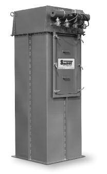
43 SECTION 3 FILTER & BAG HOUSE COMPONENTS Square Filters PRODUCT DESCRIPTION The standard configuration is for a Style II high-pressure pulsejet filter using 16 oz/yd 2 felted Dacron Polyester filter bags designed to be removed from the bottom of the tube sheet. The unit will have: Compressed air header Rated for 17-inch W.C. Mineral reinforced nylon bag cups and venturiis Stainless steel bag clamps Diaphragm valves pre-plumbed to solenoids Smart timer board with built-in LED readout, switch & 4-20 ma output capability of differential pressure readings NEMA 4 solenoid valves standard Timer and solenoids mounted in a NEMA 4 enclosures 1 ea. hinged side access door Filter bag catch grate Materials of construction: carbon steel (standard) When using Filter Elements instead of bags, elements are 8 oz/yd 2 spun bound polyester. The standard element is 45-pleat construction, with wide pleat speacing available. PRODUCT OPTIONS Stainless steel construction available upon request 60 and 70 hopper (Style III) available PTFE coating to bags High temperature (375 F)* NEMA 7/9 enclosure 304 stainless steel product contact Top load bags and cages *High temperature includes: Paint changed to high temp paint, bags changed to 14 oz/yd 2 Nomex, Diaphragm valves changed to Viton, Poly-flo tubing from diaphragm to solenoids changed to copper tubing, door gasket changed to red silicone. S3-1
44 SECTION 3 FILTER & BAG HOUSE COMPONENTS Square Filters SOLENOID ENCLOSURE EXHAUST FAN FLANGE ADAPTER LIFT LUGS (4) TYP. 1-INCH FNPT HIGH-PRESSURE CONNECTION (BOTH SIDES) USE ONLY ONE D 14 INCHES G TYP. 1 INCH TYP. C J J E NUMBER OF 4-INCH CENTERS TYP. F TYP. 13-INCH MAXIMUM H NUMBER OF 0.5-INCH Ø BAG CATCH GRID Dimensions & Ordering Information NUMBER OF BAGS CAGE/BAG LENGTH (INCHES) FILTER MODEL NUMBER BAG FILTER AREA 45-PLEAT CARTRIDGE WEIGHT (POUNDS) HEIGHT C (INCHES) 36 36BV BV * BV * BV * BV BV * BV * BV * BV BV * BV * BV * BV BV * BV * BV * D (INCHES) E (QUANTITY) FLANGE SPECIFICATIONS F (INCHES) G (INCHES) H (QUANTITY) J (INCHES) *Sizes of longer cartridges that may be available. Consult Smoot with your specific application information. S3-2
45 SECTION 3 FILTER & BAG HOUSE COMPONENTS Round Filters PRODUCT DESCRIPTION The standard configuration is for a Style III high-pressure pulsejet filter using 16 oz/yd 2 felted Dacron Polyester filter bags designed to be removed from the bottom of the tube sheet. The unit will have: Compressed air header Rated for 8.5 PSIG Positive; 17-inch Hg Gauge negative Mineral reinforced nylon bag cups and venturiis Stainless steel bag clamps diaphragm valves pre-plumbed to solenoids Smart timer board with built-in LED readout, switch & 4-20 ma output capability of differential pressure readings Timer and solenoids mounted in a NEMA 4 enclosure 1 ea. hinged food grade side access door 60 hopper Materials of construction: carbon steel (standard) When using Filter Elements instead of bags, elements are 8 oz/yd 2 spun bound polyester. The standard element is 45-pleat construction, with wide pleat speacing available. PRODUCT OPTIONS Stainless steel construction available upon request 70 hopper available Support structure (Up to 54 inches clear) PTFE coating to bags High temperature (375 F)* NEMA 7/9 enclosure 304 Stainless Steel gas contact Top load bags and cages *High temperature includes: Paint changed to high temp paint, bags changed to 14 oz/yd 2 Nomex, Diaphragm valves changed to Viton, Poly-flo tubing from diaphragm to solenoids changed to copper tubing, door gasket changed to red silicone. S3-3
46 SECTION 3 FILTER & BAG HOUSE COMPONENTS Round Filters CLEANING 180 SOLENOID ENCLOSURE DØ 1-INCH FNPT HIGH-PRESSURE CONNECTION (BOTH SIDES) USE ONLY ONE CLEAN AIR OUTLET E REF INCH FPT CONNECTION FOR GA & SW (GA & SW MUST BE PURCHASED SEPARATELY) TANGENTIAL 0 SHOWN HALF D + 6 INCHES F FILTER ACCESS 180 DOOR OPENING SIZES: 16 IN x 32 IN : 36-INCH LARGE FILTER 16 IN x 46 IN : 48-INCH TO 96-INCH LARGE FILTER 6 INCHES HALF D HALF INLET Ø SAFETY GRID 90 HALF Ø + 2 INCHES 1 INCH HALF D + 13 INCHES CLEAN AIR 90 SHOWN 60 U 1.25-INCH NPT HALF 90 HOPPER ACCESS INCHES APPLICATION REQUIRED DISTANCE 0.5 INCH Dimensions & Ordering Information NUMBER OF BAGS CAGE/BAG LENGTH FILTER MODEL NUMBER BAG FILTER AREA 45-PLEAT CARTRIDGE WEIGHT (POUNDS) HEIGHT F (INCHES) 36 36FR FR FR FR FR FR FR FR FR FR FR FR FR FR N/A FR FR FR FR BV N/A FLANGE DIMENSIONS (INCHES) D E G H I /4 8-3/8 14-1/ /4 11-3/ / /8 26-3/4 13-3/8 23-3/ /4 15-7/8 27-1/2 S3-4


47 SECTION 3 FILTER & BAG HOUSE COMPONENTS Bags & Cages PRODUCT DESCRIPTION Smoot offers virtually all types of replacement filter bags and support cages for dust collectors and filtration equipment for any type, size, style or manufacturer. Filter medias offered include Cotton, Polyester, Polypropylene, P-84 Laminates, PTFE Membrane and Ryton to name a few. Pleated filter bags and cartridges offer an alternative to optimizing your current dust collector or pneumatic receiver. They will also provide better filtration efficiencies over bags in most applications providing 3 to 5 times the filtration surface area. Additionally, pleated bags and cartridges are easier to clean than conventional filter bags because they are surface loaded, meaning the dust particles do not penetrate the media surface. Surface loading also reduces the pressure drop making pulse cleaning more efficient and economical to operate. Replacement filter bags, cages and cartridge filters for horizontal and vertical dust collectors and pneumatic receivers for other OEM units can be purchased through Smoot. Manufacturer units we service outside of Smoot include American Air Filter, Donaldson, Farr, Flex-Kleen, MAC, Pneumafil, Scientific Dust Collectors, Torit, Wheelabrator and most domestic and foreign OEM equipment. All filter bags and cartridge filters meet or exceed government requirements and industry standards. S3-5


48 SECTION 3 FILTER & BAG HOUSE COMPONENTS Replacement Parts PRODUCT DESCRIPTION Smoot offers a full line of replacement parts and components for filters, bin vents, bag houses and most filtration equipment. Diaphragm Valve with Solenoid Flanged Style Magnehelic Gauge Diaphragm Valve Compression Style Vacuum Gauge Diaphragm valves Solenoid valves Diaphragm and solenoid valve repair kits Compressed air header tanks Bulkhead fittings Pressure gauges Compressed air pressure controllers Compressed air water separation and drying Pulse timing controller boards Complete timer box assemblies available with NEMA 4, NEMA 4X and NEMA 7/9 classified and rated enclosures Magnehelic gauges Photohelic gauges Bag cups and venturis Level indicators and other ancillary products Contact your Smoot Service Center representative for assurance with part identification and troubleshooting when required. Pressure Gauge Pulse Jet Filter Timer Assembly with Integral Photohelic Switch & Gauge S3-6
49 SECTION 3 FILTER & BAG HOUSE COMPONENTS Cyclones PRODUCT DESCRIPTION Cyclones are most commonly used for the separation of product and materials from a gas/air stream. Once completed, the material is discharged through the bottom of the cyclone and the gas/air exhausts through the top. L M FØ 4.5 INCHES High efficiency design for maximum material/air separation Constructed of aluminum, carbon steel or 304 stainless steel Bottom flange fabricated to mate Smoot rotary valves, ANSI flange pattern drilling or existing equipment P AØ CØ 7/16-INCH Ø HOLES (4) J N B 1-INCH REF. H Cyclone Dimensions AØ B CØ FØ H J L M N P / / / /8 3-1/ / /2 20-3/4 18-3/4 2-3/8 11-3/ / / /2 4-1/ / / / / / / /8 5-9/ /2 6-5/ / /2 16-1/ / /2 29-1/2 27-1/2 3-3/4 17-1/4 6-5/ / /2 30-1/2 28-1/2 4-1/4 18-1/2 S3-7


50 SECTION 4 BLOWER PACKAGES & BLOWER COMPONENTS TABLE OF CONTENTS SECTION 4 Blower Packages and Blower Components BLOWER PACKAGES Pressure Blower Packages S4-1 Vacuum Blower Packages S4-2 REPLACEMENT PARTS Positive Displacement Blowers S4-3 Filter Elements for Inlet & Inline Filters S4-3 Pressure and Vacuum Relief Valves S4-3 Pressure and Vacuum Gauges S4-4 Temperature Switches and Gauges S4-4 Sound Enclosures S4-4 SECTION 4 BLOWER PACKAGES & BLOWER COMPONENTS S4-0

51 SECTION 4 BLOWER PACKAGES & BLOWER COMPONENTS Pressure Blower Packages PACKAGE DESCRIPTION The workhorse of the pneumatic conveying industry today, the Positive Displacement Blower Package offers a cost effective reliable means of generating consistent airflows from 60 to 8,000 ICFM with pressures up to 25 PSIG. With nearly 50 years of industry experience, Smoot s package design provides a package with easy maintenance access and reduced noise generation to meet even the most strident customer s needs. PACKAGE FEATURES Premium grade inlet and discharge silencers Intake air filter. Pleated polyester element with pre filter and rain hood Spring loaded pressure relief valve for mechanical safety relief Check valve to prevent material from backing up into the blower in shut down Tubular carbon steel base construction, painted V-Belt drive package with guard Built around positive displacement pressure blowers Combination pressure gauge and NEMA 4 pressure switch Includes a TEFC motor on an easily adjustable base PACKAGE OPTIONS PD blower manufacturers utilized include MD-Tuthill, Roots, Gardner-Denver, Aerzen, Kaeser and others Temperature gauges and sensors Pressure transmitters to send a continuous 4-20mA indication of the current pressure level to a remote location Sound enclosures to dampen noise to even lower levels if needed Variable speed drive packages for easy adjustment of airflows INTAKE FILTER SIDE VIEW TOP VIEW INTAKE SILENCER MOTOR TOTALLY ENCLOSED BELT GUARD V-BELT DRIVE BLOWER BASE PRESSURE RELIEF VALVE HIGH-PRESSURE GAUGE & SWITCH POSITIVE DISPLACEMENT BLOWER DISCHARGE CONNECTION DISCHARGE SILENCER S4-1

52 SECTION 4 BLOWER PACKAGES & BLOWER COMPONENTS Vacuum Blower Packages PACKAGE FEATURES Premium grade discharge silencer Inline air filter. Pleated polyester element with pre filter and vacuum rated canister Spring loaded vacuum relief valve for mechanical safety relief Vacuum breaker valve for efficient operation of system Tubular carbon steel base construction, painted V-Belt drive package with cover Built around positive displacement blowers Combination vacuum gauge and NEMA 4 vacuum switch Includes a TEFC motor on an easily adjustable base PACKAGE DESCRIPTION The workhorse of the pneumatic conveying industry today, the Positive Displacement Blower Package offers a cost effective reliable means of generating consistent airflows from 60 to 8,000 ICFM with vacuum levels up to 17 inches Hg. With nearly 50 years of industry experience, Smoot s package design provides a package with easy maintenance access and reduced noise generation to meet even the most strident customer s needs. PACKAGE OPTIONS PD blower manufacturers utilized include MD-Tuthill, Roots, Gardner-Denver, Aerzen, Kaeser and others Temperature gauges and sensors Vacuum transmitters to send a continuous 4-20mA indication of the current vacuum level to a remote location Sound enclosures to dampen noise to even lower levels if needed Variable speed drive packages for easy adjustment of airflows SIDE VIEW TOP VIEW INLINE FILTER (OPTIONAL) INLET SILENCER VACUUM RELIEF VALVE VACUUM GAUGE HIGH VACUUM SWITCH MOTOR TOTALLY ENCLOSED BELT GUARD V-BELT DRIVE ISOLATION JOINT HOSE CLAMP BLOWER BASE POSITIVE DISPLACEMENT BLOWER OUTLET SILENCER S4-2
. Standard, medium and heavy-duty models available.")


53 SECTION 4 BLOWER PACKAGES & BLOWER COMPONENTS Replacement Parts POSITIVE DISPLACEMENT BLOWERS All major makes and models are available (Duroflow, MD Pneumatics, ROOTS, Sutorbilt ). Standard, medium and heavy-duty models available. For operation in nonstandard conditions, contact the Smoot Service Center. A blower replacement for your application. Cutaway View INLINE FILTER HOUSINGS AND REPLACEMENT ELEMENTS Durable heavy gauge base with low pressure drop yoke and pipe design. Larger units reinforced with gussets for machine with extreme vibration. Interchangeable elements. Low entry velocity air gap between base and cover. Several element sizes available at a given connection size providing a choice according to the severity of application. Stainless steel, hot dip galvanized and epoxy coated housings available. Replacement filters elements available for all manufacturers. Custom filters quoted upon request. PRESSURE AND VACUUM RELIEF VALVES Cast iron with bronze nozzle, disc and guide. Large seat area/guide area ratio. Disc pivot design insures top valve performance. Reversible lift lever. Flat bronze valve seats are lapped for optimum performance. Every valve tested for vacuum/pressure settings and leakage. All adjustments are factory sealed to prevent tampering. S4-3

54 SECTION 4 BLOWER PACKAGES & BLOWER COMPONENTS Replacement Parts PRESSURE AND VACUUM GAUGES Broad line of gauges for demanding pressure and vacuum applications. Standard liquid fill is glycerin. Silicon and mineral oils available. Specify dial size and mounting configuration when ordering. TEMPERATURE SWITCHES AND GAUGES Complete line of point level switches and continuous transmitters Gauge face and LED readouts available -40 F to +500 F range availability Specify required range and mounting when ordering SOUND ENCLOSURES Designed to reduce noise levels of positive displacement blowers, industrial fans and other rotating equipment Noise reduction designs to meet or exceed OSHA, MSHA or specific plant maximum noise levels accepted Painted and/or Galvanized carbon steel materials of construction Stainless steel or aluminum construction available upon request Indoor and outdoor enclosures designs available Exhaust fans and heaters provided when required Contact Smoot and we ll assist with a solution to any noise reduction challenges you may encounter S4-4


55 SECTION 5 CONVEY LINE & CONVEY LINE ACCESSORIES TABLE OF CONTENTS SECTION 5 Convey Line & Convey Line Accessories COUPLINGS Compression-Style Coupling S5-1 Compression-Style Coupling with Side Bands S5-1 High-Pressure Couplings for Plain-End Pipe S5-2 High-Pressure Couplings for Grooved-End Pipe S5-2 Quick-Connect, Cam-and-Groove Couplings S5-3 TUBING AND PIPE Tubing & Pipe Straight Lengths S5-9 Internal-Spiral-Grooved Pipe and Tube S5-10 Directional, Shot-Peened Pipe S5-10 Standard Short- and Long-Radius Elbows S5-11 Convey Line Sight Glasses S Wearback Elbows S Wearback Elbows with Replaceable Channel S5-14 Wear-Resistant, Ceramic-Wrapped Elbows S5-15 Standard and Special Welded Fabrications S5-16 Flexible Hose, Rubber 688 SB Bulk Commodity S5-17 Flexible Hose, Rubber 690 SB Bulk Commodity S5-17 Flexible Hose, PVC S5-18 Flexible Hose Accessories S5-18 Flexible Hose Assemblies S5-18 Hose Stations S5-19 Vacuum Breaker Valves S5-20 Vacuum Modulating Valves S5-20 SECTION 5 CONVEY LINE & CONVEY LINE ACCESSORIES S5-0


56 SECTION 5 CONVEY LINE & CONVEY LINE ACCESSORIES Compression-Style Couplings COMPRESSION-STYLE COUPLING Compression Couplings provide a positive seal for dilute phase pressure and vacuum pneumatic convey lines when joining plain end tubing, pipe, elbows and other line components. These couplings are available in different bolt count arrangements, with a wide variety of gaskets for use in a vast range of applications. Whether your application is low pressure conveying Aggregates, Food Products or Chemicals we can assist you in the identification of the right compression coupling arrangement for your needs. Remember when ordering these couplings for a Vacuum system to include the Gasket Protector to extend the coupling life. This style of compression coupling is generally used in systems with pressures of 15 PSI or less. The assembly and disassembly of these couplings is fast and easy. Provides equalized pressure seal Provided ready to install Available in galvanized steel, aluminum or stainless steel Includes inner sleeve for positive seal and extra rigidity Available with black neoprene, white neoprene, high temperature as well as other gasket material Available from 0.75-inch to 24-inch, tubing and pipe COMPRESSION-STYLE COUPLING Dual-locking side bands grip the pipe and allow higher operating pressures than standard compression couplings usually allow. These are especially effective in resisting line end pull and providing a superior connection when excessive vibration may be present. They have also proved to be extremely useful when repairing sections of convey lines, while also providing a positive seal. As found in the standard compression coupling assembly and disassembly is fast and easy. Provide vastly improved axial force holding power to connect or repair pipe and tube Allows higher operating pressure then normally suggested for compression type coupling Especially effective where line vibration is a problem Available from 2-inch O.D through 24-inch O.D. nominal pipe or tubing sizes Complete coupling, or conversion kits available for existing couplings S5-1
.")
57 SECTION 5 CONVEY LINE & CONVEY LINE ACCESSORIES High-Pressure Couplings HIGH-PRESSURE COUPLING FOR PLAIN-END PIPE Specially designed for plain-end steel and stainless-steel pipe. Gripping teeth provide a strong component for joining plain and beveled end (including Schedule 80 steel pipe). Not to be used on plastic pipe, pipe with brittle linings, cast or ductile iron pipe, nor any pipe with a surface hardness greater than 150 Brinell. Encased in a durable ductile iron housing Curved, case-hardened steel jaws grip into pipe when nuts are tightened to full torque specification and it requires no pipe end preparation Available in pipe sizes 1-inch through 4-inch HIGH-PRESSURE COUPLING FOR GROOVED-END PIPES The Style 177 couplings are easily installed without the need to disassemble the bolts, nuts, gasket and housings making installation faster, easier and safer than any other welded, flanged or standard grooved couplings. Crews can assemble a grooved joint by inserting the new installation-ready coupling onto the ends of a pipe, fitting, valve or accessory and tightening the nuts using standard hand tools or an impact gun. No loose components means a safer, cleaner and more efficient jobsite, where installers do not need to disassemble the coupling in order to install. Encased in a durable ductile iron housing Designed with cross-ribbed construction to provide a strong component for pressure piping systems Sizes 3/4-inch to 12-inch (20 mm to 300 mm) are two-piece housings Sizes 14-inch to 22-inch (350 mm to 550 mm) are cast in four identical segments, with larger sizes cast in six segments S5-2
58 SECTION 5 CONVEY LINE & CONVEY LINE ACCESSORIES Quick-Connect, Cam-and-Groove Couplings QUICK-CONNECT, CAM-AND-GROOVE COUPLINGS Smoot Company distributes high quality quick connect/disconnect style couplings, sometimes referred to as QD Couplings, and their respective replacement parts. We present proven solutions at competitive pricing for most all QD Coupling applications available on the market today. If you need assistance when specifying or ordering QD Couplings our knowledgeable sales staff will assist you through the selection process. Sizes available from 1/2-inch through 12-inch for many types Constructed of cast brass, aluminum, stainless steel, malleable iron or forged brass. Operating temperatures up to 450 F Operating pressures up to 350 psig STANDARD CONSTRUCTION MATERIALS Cast Brass Aluminum 316 Stainless Steel Malleable Iron Polypropylene Forged Brass OPTIONAL CONSTRUCTION MATERIALS CONTACT THE SERVICE CENTER FOR PRICING Hard-Coat Aluminum Hastalloy C Anodized Alumimum Carpenter 20 Monel MATERIAL ALUMINUM (not for use above 300 F) FORGED BRASS CAST BRASS MALLEABLE IRON STAINLESS STEEL MONEL POLYPROPYLENE Recommended Operating Conditions by Materials and Conveyance Diameter GASKET Standard gasket +225 F Viton gasket +350 F* (Teflon gaskets also available) Standard gasket +225 F Viton gasket +350 F** Teflon gasket +450 F** Standard gasket +225 F Viton gasket +350 F* (Teflon gaskets also available) Standard gasket +225 F; Viton gasket +350 F* (Teflon gaskets also available) Standard gasket +225 F Viton gasket +350 F** Teflon gasket +450 F** Standard gasket +225 F Viton gasket +350 F** Teflon gasket +450 F** Standard gasket +70 F Standard gasket +200 F * For temperatures in excess of +225 F consult the Service Center for pressure ratings. ** For temperatures in excess of +300 F consult the Service Center for pressure ratings. MAXIMUM WORKING PRESSURE 1/2 to 3/4 SIZE IN INCHES 1 1-1/4 1-1/ / psi X X X X X 150 psi X 125 psi X 100 psi X 75 psi X X 350 psi X X X X X 250 psi X X 100 psi X 200 psi X X X X X 150 psi X 125 psi X 100 psi X 75 psi X X 125 psi X X 100 psi X X X 250 psi X X X X X 200 psi X 100 psi X 250 psi X X X X X 200 psi X 150 psi X 100 psi X 100 psi X X X X X 50 psi X X X X X S5-3
59 SECTION 5 CONVEY LINE & CONVEY LINE ACCESSORIES Quick-Connect, Cam-and-Groove Couplings D C F A B G J L E M K H PART A PART E PART F DUST PLUG N S V T Z O W X AA P U Y R Couplers Typical dimensions in inches for aluminum* SIZE A B C D E F G H J K L M 1/2 2-11/16 1-1/2 1-15/ /16 9/16 1-3/16 3-7/16 5/ /32 23/32 1-1/4 7/16 3/4 4-1/2 2-7/8 1-3/8 2-1/16 3/4 1-5/16 3-3/4 1/2 2-1/16 59/64 1-1/4 5/ /8 2-3/16 1-9/16 2-7/ /16 4-1/16 3/4 2-15/32 1-5/ /16 9/16 1-1/4 7-3/16 3-3/16 2-3/16 2-3/16 1-1/4 1-13/16 4-1/ /32 1-1/4 2-1/16 5/8 1-1/2 7-1/2 3-1/2 1-7/8 2-3/4 1-3/8 1-13/16 4-9/ /16 2-3/4 1-5/8 2 3/ /8 3-7/8 1-3/16 3-1/ /8 4-15/ / / /4 2-1/2 8-7/16 4-7/16 2-1/4 3-1/2 2-3/8 2-5/8 5-7/16 2-3/16 3-3/8 2-3/8 3-1/16 3/ /16 5-5/8 2-3/8 3-9/16 2-7/8 2-5/16 6-7/8 2-5/8 3-1/2 2-7/8 3-1/4 3/ /16 6-3/4 2-7/ /16 2-7/8 7-3/16 3-9/ /16 2-5/8 3/ /16 7-3/4 2-1/ /4 2-7/16 7-5/16 4-5/8 4-1/16 4-3/4 2-11/16 7/ / /8 2-11/16 4-3/4 5-15/16 2-5/8 8-5/16 5-9/16 4-1/4 5-11/ /16 1-1/ /4 12-7/ / /16 7-7/8 3-15/ /16 7-1/2 6-1/16 7-3/4 4-3/8 1-5/8 Adapters Typical dimensions in inches for aluminum* SIZE N O P R S T U V W X Y Z AA 1/ /16 9/16 1-3/16 5/16 3-3/8 1-5/ /8 1-9/32 9/16 19/32 1-1/32 3/4 1-3/8 1-17/32 3/4 1-7/8 5/16 4-3/16 1-3/4 1-3/8 2-3/16 1-3/8 3/4 7/16 1-1/ /16 2-1/8 1-1/8 1-3/4 3/4 4-7/ /16 2-9/ /16 31/32 9/16 1-1/4 1-1/4 2-15/16 2-1/8 1-1/ /4 2-3/8 1-15/ /8 1-1/8 5/8 1-3/8 1-1/2 2-9/32 2-3/16 1-3/8 2-7/32 1-1/4 4-5/8 2-1/4 2-1/4 3-3/32 2-3/16 1-3/8 11/16 1-3/ /16 2-7/ /32 5-5/8 1-11/16 5-3/8 2-3/8 2-11/16 3-3/8 2-7/16 1-3/4 3/4 2-1/16 2-1/2 3-5/ /16 2-5/32 3-5/16 2-5/ /8 3-1/16 3-7/8 2-11/16 2-5/32 11/16 1-7/ /16 2-3/4 2-7/ /8 6-11/ / / /16 2-3/4 2-7/8 7/8 2-1/ /16 3-7/8 5-3/16 3-5/8 5-1/2 2-3/4 4-7/8 4-1/2 3-1/ /32 7/8 2-3/ /16 4-7/ /8 7-7/16 3-1/ / / / / /32 7-5/32 5-9/16 8-7/8 3-1/ / / /16 1-1/4 2-5/ /2 5-1/2 7-9/ /16 7-3/4 11-7/8 3-7/8 9-1/2 6-1/4 4-1/2 7-3/4 1-5/8 4-1/16 * For the dimensions associated with other available materials, please contact the Service Center. S5-4


60 SECTION 5 CONVEY LINE & CONVEY LINE ACCESSORIES Quick-Connect, Cam-and-Groove Couplings MALE ADAPTERS / FEMALE THREAD BSP and BST threads available on request Also available in 8-inch and 10-inch sizes SIZE INCHES CB CAST BRASS ORDER NUMBER BY METAL SELECTION AL ALUMINUM* SS 316 STAINLESS MI MALLEABLE IRON PP POLYPROPYLENE BR FORGED BRASS 1/2 5ACB 5AAL 5ASS 5AMI N/A 5ABR 3/4 7ACB 7AAL 7ASS 7AMI 7APP 7ABR 1 10ACB 10AAL 10ASS 10AMI 10APP 10ABR 1-1/4 12ACB 12AAL 12ASS 12AMI 12APP 12ABR 1-1/2 15ACB 15AAL 15ASS 15AMI 15APP 15ABR 2 20ACB 20AAL 20ASS 20AMI 20APP 20ABR 2-1/2 25ACB 25AAL 25ASS 25AMI N/A 25ABR 3 30ACB 30AAL 30ASS 30AMI 30APP 30ABR 4 40ACB 40AAL 40ASS 40AMI N/A 40ABR 5 50ACB 50AAL 50ASS 50AMI N/A N/A 6 60ACB 60AAL 60ASS 60AMI N/A N/A FEMALE COUPLERS / MALE THREAD BSP and BST threads available on request Also available in 8-inch and 10-inch sizes Aluminum couplers are standard with stainless-steel handles; brass handles available on request SIZE INCHES CB CAST BRASS ORDER NUMBER BY METAL SELECTION AL ALUMINUM* SS 316 STAINLESS MI MALLEABLE IRON PP POLYPROPYLENE BR FORGED BRASS 1/2 5BCB 5BAL 5BSS 5BMI N/A 5BBR 3/4 7BCB 7BAL 7BSS 7BMI 7BPP 7BBR 1 10BCB 10BAL 10BSS 10BMI 10BPP 10BBR 1-1/4 12BCB 12BAL 12BSS 12BMI 12BPP 12BBR 1-1/2 15BCB 15BAL 15BSS 15BMI 15BPP 15BBR 2 20BCB 20BAL 20BSS 20BMI 20BPP 20BBR 2-1/2 25BCB 25BAL 25BSS 25BMI N/A 25BBR 3 30BCB 30BAL 30BSS 30BMI 30BPP 30BBR 4 40BCB 40BAL 40BSS 40BMI N/A 40BBR 5 50BCB 50BAL 50BSS 50BMI N/A N/A 6 60BCB 60BAL 60BSS 60BMI N/A N/A FEMALE COUPLERS / HOSE SHANK Also available in 8-inch and 10-inch sizes Aluminum couplers are standard with stainless-steel handles; brass handles available on request SIZE INCHES CB CAST BRASS ORDER NUMBER BY METAL SELECTION AL ALUMINUM* SS 316 STAINLESS MI MALLEABLE IRON PP POLYPROPYLENE BR FORGED BRASS 1/2 5CCB 5CAL 5CSS 5CMI N/A 5CBR 3/4 7CCB 7CAL 7CSS 7CMI 7CPP 7CBR 1 10CCB 10CAL 10CSS 10CMI 10CPP 10CBR 1-1/4 12CCB 12CAL 12CSS 12CMI 12CPP 12CBR 1-1/2 15CCB 15CAL 15CSS 15CMI 15CPP 15CBR 2 20CCB 20CAL 20CSS 20CMI 20CPP 20CBR 2-1/2 25CCB 25CAL 25CSS 25CMI N/A 25CBR 3 30CCB 30CAL 30CSS 30CMI 30CPP 30CBR 4 40CCB 40CAL 40CSS 40CMI N/A 40CBR 5 50CCB 50CAL 50CSS 50CMI N/A N/A 6 60CCB 60CAL 60CSS 60CMI N/A N/A 3-inch and 4-inch aluminum are provided with machined shanks FEMALE COUPLERS / FEMALE THREAD BSP and BST threads available on request Also available in 8-inch and 10-inch sizes Aluminum couplers are standard with stainless-steel handles; brass handles available on request SIZE INCHES CB CAST BRASS ORDER NUMBER BY METAL SELECTION AL ALUMINUM* SS 316 STAINLESS MI MALLEABLE IRON PP POLYPROPYLENE BR FORGED BRASS 1/2 5DCB 5DAL 5DSS 5DMI N/A 5DBR 3/4 7DCB 7DAL 7DSS 7DMI 7DPP 7DBR 1 10DCB 10DAL 10DSS 10DMI 10DPP 10DBR 1-1/4 12DCB 12DAL 12DSS 12DMI 12DPP 12DBR 1-1/2 15DCB 15DAL 15DSS 15DMI 15DPP 15DBR 2 20DCB 20DAL 20DSS 20DMI 20DPP 20DBR 2-1/2 25DCB 25DAL 25DSS 25DMI N/A 25DBR 3 30DCB 30DAL 30DSS 30DMI 30DPP 30DBR 4 40DCB 40DAL 40DSS 40DMI N/A 40DBR 5 50DCB 50DAL 50DSS 50DMI N/A N/A 6 60DCB 60DAL 60DSS 60DMI N/A N/A S5-5


61 SECTION 5 CONVEY LINE & CONVEY LINE ACCESSORIES Quick-Connect, Cam-and-Groove Couplings SIZE INCHES CB CAST BRASS ORDER NUMBER BY METAL SELECTION AL ALUMINUM* SS 316 STAINLESS MI MALLEABLE IRON PP POLYPROPYLENE BR FORGED BRASS 1/2 5ECB 5EAL 5ESS 5EMI N/A 5EBR 3/4 7ECB 7EAL 7ESS 7EMI 7EPP 7EBR 1 10ECB 10EAL 10ESS 10EMI 10EPP 10EBR 1-1/4 12ECB 12EAL 12ESS 12EMI 12EPP 12EBR 1-1/2 15ECB 15EAL 15ESS 15EMI 15EPP 15EBR 2 20ECB 20EAL 20ESS 20EMI 20EPP 20EBR 2-1/2 25ECB 25EAL 25ESS 25EMI N/A 25EBR 3 30ECB 30EAL 30ESS 30EMI 30EPP 30EBR 4 40ECB 40EAL 40ESS 40EMI N/A 40EBR 5 50ECB 50EAL 50ESS 50EMI N/A N/A 6 60ECB 60EAL 60ESS 60EMI N/A N/A 3-inch and 4-inch aluminum are provided with machined shanks MALE ADAPTERS / HOSE SHANK Also available in 8-inch and 10-inch sizes SIZE INCHES CB CAST BRASS ORDER NUMBER BY METAL SELECTION AL ALUMINUM* SS 316 STAINLESS MI MALLEABLE IRON PP POLYPROPYLENE BR FORGED BRASS 1/2 5FCB 5FAL 5FSS 5FMI N/A 5FBR 3/4 7FCB 7FAL 7FSS 7FMI 7FPP 7FBR 1 10FCB 10FAL 10FSS 10FMI 10FPP 10FBR 1-1/4 12FCB 12FAL 12FSS 12FMI 12FPP 12FBR 1-1/2 15FCB 15FAL 15FSS 15FMI 15FPP 15FBR 2 20FCB 20FAL 20FSS 20FMI 20FPP 20FBR 2-1/2 25FCB 25FAL 25FSS 25FMI N/A 25FBR 3 30FCB 30FAL 30FSS 30FMI 30FPP 30FBR 4 40FCB 40FAL 40FSS 40FMI N/A 40FBR 5 50FCB 50FAL 50FSS 50FMI N/A N/A 6 60FCB 60FAL 60FSS 60FMI N/A N/A MALE ADAPTERS / MALE THREAD BSP and BST threads available on request Also available in 8-inch and 10-inch sizes SIZE INCHES CB CAST BRASS ORDER NUMBER BY METAL SELECTION AL ALUMINUM* SS 316 STAINLESS MI MALLEABLE IRON PP POLYPROPYLENE BR FORGED BRASS 1/2 5DPCB 5DPAL 5DPSS 5DPMI N/A 5DPBR 3/4 7DPCB 7DPAL 7DPSS 7DPMI 7DPPP 7DPBR 1 10DPCB 10DPAL 10DPSS 10DPMI 10DPPP 10DPBR 1-1/4 12DPCB 12DPAL 12DPSS 12DPMI 12DPPP 12DPBR 1-1/2 15DPCB 15DPAL 15DPSS 15DPMI 15DPPP 15DPBR 2 20DPCB 20DPAL 20DPSS 20DPMI 20DPPP 20DPBR 2-1/2 25DPCB 25DPAL 25DPSS 25DPMI N/A 25DPBR 3 30DPCB 30DPAL 30DPSS 30DPMI 30DPPP 30DPBR 4 40DPCB 40DPAL 40DPSS 40DPMI N/A 40DPBR 5 50DPCB 50DPAL 50DPSS 50DPMI N/A N/A 6 60DPCB 60DPAL 60DPSS 60DPMI N/A N/A DUST PLUG For use with couplers Not for use in pressure applications Also available in 8-inch and 10-inch sizes SIZE INCHES CB CAST BRASS ORDER NUMBER BY METAL SELECTION AL ALUMINUM* SS 316 STAINLESS MI MALLEABLE IRON PP POLYPROPYLENE BR FORGED BRASS 1/2 5DCCB 5DCAL 5DCSS 5DCMI N/A 5DCBR 3/4 7DCCB 7DCAL 7DCSS 7DCMI 7DCPP 7DCBR 1 10DCCB 10DCAL 10DCSS 10DCMI 10DCPP 10DCBR 1-1/4 12DCCB 12DCAL 12DCSS 12DCMI 12DCPP 12DCBR 1-1/2 15DCCB 15DCAL 15DCSS 15DCMI 15DCPP 15DCBR 2 20DCCB 20DCAL 20DCSS 20DCMI 20DPCP 20DCBR 2-1/2 25DCCB 25DCAL 25DCSS 25DCMI N/A 25DCBR 3 30DCCB 30DCAL 30DCSS 30DCMI 30DCPP 30DCBR 4 40DCCB 40DCAL 40DCSS 40DCMI N/A 40DCBR 5 50DCCB 50DCAL 50DCSS 50DCMI N/A N/A 6 60DCCB 60DCAL 60DCSS 60DCMI N/A N/A DUST CAP For use with adapters Not for use in pressure applications Also available in 8-inch and 10-inch sizes Aluminum couplers are standard with stainless-steel handles; brass handles available on request For Electric Motor Dimensions, contact The Service Center. S5-6
62 SECTION 5 CONVEY LINE & CONVEY LINE ACCESSORIES Quick-Connect, Cam-and-Groove Couplings COUPLINGS FOR BUTT WELD (BW) OR SOCKET WELD (SW) ADAPTERS Specify tube size or pipe size schedule Also available in 8-inch and 10-inch sizes SIZE INCHES BUTT WELD ADAPTER BR FORGED BRASS AL ALUMINUM SS 316 STAINLESS SOCKET WELD ADAPTER BR FORGED BRASS AL ALUMINUM SS 316 STAINLESS 1 10ABWBR 10ABWAL 10ABWSS 10ASWBR 10ASWAL 10ASWSS 1-1/2 15ABWBR 15ABWAL 15ABWSS 15ASWBR 15ASWAL 15ASWSS 2 20ABWBR 20ABWAL 20ABWSS 20ASWBR 20ASWAL 20ASWSS 2-1/2 25ABWBR 25ABWAL 25ABWSS 25ASWBR 25ASWAL 25ASWSS 3 30ABWBR 30ABWAL 30ABWSS 30ASWBR 30ASWAL 30ASWSS 4 40ABWBR 40ABWAL 40ABWSS 40ASWBR 40ASWAL 40ASWSS 5 50ABWBR 50ABWAL 50ABWSS 50ASWBR 50ASWAL 50ASWSS 6 60ABWBR 60ABWAL 60ABWSS 60ASWBR 60ASWAL 60ASWSS COUPLINGS FOR BUTT WELD (BW) OR SOCKET WELD (SW) COUPLERS Specify tube size or pipe size schedule Also available in 8-inch and 10-inch sizes SIZE INCHES BUTT WELD COUPLER BR FORGED BRASS AL ALUMINUM SS 316 STAINLESS SOCKET WELD COUPLER BR FORGED BRASS AL ALUMINUM SS 316 STAINLESS 1 10DBWBR 10DBWAL 10DBWSS 10DSWBR 10DSWAL 10DSWSS 1-1/2 15DBWBR 15DBWAL 15DBWSS 15DSWBR 15DSWAL 15DSWSS 2 20DBWBR 20DBWAL 20DBWSS 20DSWBR 20DSWAL 20DSWSS 2-1/2 25DBWBR 25DBWAL 25DBWSS 25DSWBR 25DSWAL 25DSWSS 3 30DBWBR 30DBWAL 30DBWSS 30DSWBR 30DSWAL 30DSWSS 4 40DBWBR 40DBWAL 40DBWSS 40DSWBR 40DSWAL 40DSWSS 5 50DBWBR 50DBWAL 50DBWSS 50DSWBR 50DSWAL 50DSWSS 6 60DBWBR 60DBWAL 60DBWSS 60DSWBR 60DSWAL 60DSWSS COUPLINGS FOR DRY PRODUCTS ADAPTERS (STRAIGHT THREAD) SIZE INCHES ADAPTERS (STRAIGHT THREAD) BR FORGED BRASS AL ALUMINUM SS 316 STAINLESS 1 10ASBR 10ASAL 10ASSS 1-1/2 15ASBR 15ASAL 15ASSS 2 20ASBR 20ASAL 20ASSS 2-1/2 25ASBR 25ASAL 25ASSS 3 30ASBR 30ASAL 30ASSS 4 40ASBR 40ASAL 40ASSS 5 50ASBR 50ASAL 50ASSS 6 60ASBR 60ASAL 60ASSS 3 x ASBR N/A N/A 4 x ASBR 4030ASAL N/A COUPLINGS FOR DRY PRODUCTS COUPLERS (STRAIGHT THREAD) SIZE INCHES COUPLERS (STRAIGHT THREAD) BR FORGED BRASS AL ALUMINUM SS 316 STAINLESS 2 20DSBR 20DSAL 20DSSS 3 30DSBR 30DSAL 30DSSS 4 40DSBR 40DSAL 40DSSS 5 50DSBR 50DSAL 50DSSS 6 60DSBR 60DSAL 60DSSS S5-7
63 SECTION 5 CONVEY LINE & CONVEY LINE ACCESSORIES Quick-Connect, Cam-and-Groove Couplings SIZE INCHES BR FORGED BRASS FLA ADAPTERS AL ALUMINUM SS 316 STAINLESS 1 10FLABR 10FLAAL 10FLASS 1-1/2 15FLABR 15FLAAL 15FLASS 2 20FLABR 20FLAAL 20FLASS 2-1/2 25FLABR 25FLAAL 25FLASS 3 30FLABR 30FLAAL 30FLASS 4 40FLABR 40FLAAL 40FLASS 6 60FLABR 60FLAAL 60FLASS 8 80FLABR 80FLAAL 80FLASS ASA FLANGE COUPLINGS FLA ADAPTERS Standard with 150-lb, flat-face flange and bolt hole patterns for FLA parts Other flange configurations available on request SIZE INCHES BR FORGED BRASS FLB COUPLERS AL ALUMINUM SS 316 STAINLESS 1 10FLBBR 10FLBAL 10FLBSS 1-1/2 15FLBBR 15FLBAL 15FLBSS 2 20FLBBR 20FLBAL 20FLBSS 2-1/2 25FLBBR 25FLBAL 25FLBSS 3 30FLBBR 30FLBAL 30FLBSS 4 40FLBBR 40FLBAL 40FLBSS 6 60FLBBR 60FLBAL 60FLBSS 8 80FLBBR 80FLBAL 80FLBSS ASA FLANGE COUPLINGS FLB COUPLERS Standard with 150-lb, flat-face flange and bolt hole patterns for FLB parts Other flange configurations available on request SIZE INCHES LAT ADAPTERS AL ALUMINUM 2 20LATAL 3 30LATAL 4 40LATAL 6 60LATAL TANK TRUCK FLANGE COUPLINGS LAT ADAPTERS Available in aluminum only Bolt hole patterns for LAT parts available on request SIZE INCHES LBT COUPLERS AL ALUMINUM 2 20LBTAL 3 30LBTAL 4 40LBTAL 6 60LBTAL TANK TRUCK FLANGE COUPLINGS LBT COUPLERS Available in aluminum only Bolt hole patterns for LBT parts available on request SIZE INCHES PART A MALE HEAVY-DUTY BRASS COUPLINGS PART D DUST DUST FEMALE CAP PLUG GASKET 1/2 5AXB 5DXB 5DCXB 5DPXB 5GSKBUHD 3/4 7AXB 7DXB 7DCXB 7DPXB 7GSKBUHD 1 10AXB 10DXB 10DCXB 10DPXB 10GSKBUHD 1-1/4 12AXB 12DXB 12DCXB 12DPXB 12GSKBUHD 1-1/2 15AXB 15DXB 15DCXB 15DPXB 15GSKBUHD 2 20AXB 20DXB 20DCXB 20DPXB 20GSKBUHD 2-1/2 25AXB 25DXB 25DCXB 25DPXB 25GSKBUHD 3 30AXB 30DXB 30DCXB 30DPXB 30GSKBUHD 4 40AXB 40DXB 40DCXB 40DPXB 40GSKBUHD HEAVY-DUTY BRASS COUPLINGS SPECIAL DESIGN Not interchangable with standard cam-and-groove couplings S5-8
64 SECTION 5 CONVEY LINE & CONVEY LINE ACCESSORIES Tubing and Pipe TUBING AND PIPE STRAIGHT LENGTHS Available in cut-to-length; 20-ft to 40-ft random lengths Available in: aluminum carbon steel galvanized steel stainless steel MATERIAL FORM ITEM NUMBER DESCRIPTION ALLOY 6063 ASTM B-221 PIPE AND TUBING MATERIAL SPECIFICATIONS ALUMINUM CARBON STEEL STAINLESS STEEL GALVANIZED STEEL STRAIGHTS ASTM T-6 BENDS ASTM T-1 PIPE ASTM A-53 Seamless, welded black and galvanized steel pipe TUBE ASTM A-513 Electric resistance welded carbon and alloy steel for use as mechanical tubing PIPE ASTM A-312 Seamless and welded stainless steel pipe intended for high-temperature and general corrosive service. Twenty-four grades available, including 304, 316, 304L and 316L TUBE ASTM A-249 Stainless steel tubing for general corrosion resisting and low- or high-temperature service COATED PIPE ASTM A-53 Galvanized coated pipe COATED TUBE ASTM A-513 Galvanized coated tube TUBE ASTM Galvanized tube S5-9


65 SECTION 5 CONVEY LINE & CONVEY LINE ACCESSORIES Tubing and Pipe INTERNAL-SPIRAL-GROOVED PIPE AND TUBE Grooved internal surfaces disrupt boundry layer of flow, encouraging product tumble rather than sliding flow and reducing angel hair in plastic pellets. Available in aluminum or stainless steel tube and pipe Available 2-inch O.D. through 8-inch I.P.S. Sandblast and shot peened treatment also available Maximum length available is 20 feet DIRECTIONAL SHOT-PEENED PIPE Directional Shot-Peening the interior of a pipe or tube is performed to help reduce fines and streamers when conveying plastic pellets or resins in a Dilute Phase conveying process. After the interior of a pipe receives a shot-peening treatment the interior would have a dimpled roughness, this causes the air used in the convey process to create a turbulence in the line, specifically along the inner wall. This turbulence will reduce the product being conveyed from sliding down the wall of the convey line thus reducing Fines, Snake Skins and Streamers. Note: Shot-Peen treated pipe should only be used in Dilute Phase conveying systems, and is not recommended for Dense Phase convey systems. S5-10
66 SECTION 5 CONVEY LINE & CONVEY LINE ACCESSORIES Elbows Long and Short Radius STANDARD SHORT AND LONG RADIUS ELBOWS Pipe and tube bends up to 180 degrees, at a wide variety of bend radii Ceramic lined for abrasive applications Available in: aluminum carbon steel galvanized steel stainless steel Special construction available upon request The Service Center has an extensive inventory of tube bends available for three-day shipment. Most popular bend sizes are stocked in carbon-steel, aluminim and stainless-steel materials. OD Outside Diameter ST Tangent D Bend Angle in Degrees Face to End Centerline to End Setback CLR Centerline Radius Inside Radius Outside Radius ST Tangent OD TUBE SIZE PIPE SIZE OUTSIDE DIAMETER ELBOW BEND AVAILABILITY (MEASUREMENTS IN INCHES) STANDARD TANGENT (ST) COMMON CENTERLINE RADII (CLR) / / / / / / / / / / / / / / / / / tube, 6 pipe / / / tube, 7 pipe / / / tube, 8 pipe / / / FOR 90 BENDS Face-to-End = CLR + Tangent + (1/2) OD Centerline-to-End = CLR + Tangent Setback = CLR (Centerline Radius) FOR OTHER BENDS Setback = CLR x (Tangent) 1/2 bend angle Centerline-to-End = Setback + Tangent NOTES Order Bends Stat: by outside diameter, wall thickness, alloy, degree of bend, centerline radius and tangent Wall Thickness: 16-ga. (0.063), 14-ga. (0.083) and 11-ga. (0.120) tubing. Schedules 5, 10 and 40 pipe. Other wall thicknesses available on request. MATERIAL ALUMINUM STAINLESS STEEL CARBON STEEL GALVANIZED STEEL METAL SPECIFICATION PIPE 6063-T1 Extruded T304 ASTM A312 ASTM A53 Galv. A53 TUBING 6063-T1 Extruded T304 ASTM A249 ASTM A513 Galv. A513 S5-11

67 SECTION 5 CONVEY LINE & CONVEY LINE ACCESSORIES Convey Line Sight Glasses CONVEY LINE SIGHT GLASSES Allows viewing of material flow Smooth, straight-through interior Air-tight seal Viewing area available in: acrylic Pyrex Pipe or tube available in: aluminum carbon steel stainless steel Permanently attached grounding strip eliminates build up of static electricity TUBE OR PIPE INSERTED IN CLEAR ACRYLIC CLEAR ACRYLIC INSERTED IN PIPE PART NUMBER TUBE WITH ALUMINUM ENDS SIZE IN INCHES OVERALL O.D. OUTSIDE DIAMETER A TUBE O.D. OUTSIDE DIAMETER B TUBE I.D. INSIDE DIAMETER C 1-1/2-OD OD OD /4-OD /2-OD /2-OD OD OD /2-OD /2-OD OD OD /2-OD /2-OD OD OD OD PART NUMBER PIPE WITH STEEL ENDS SIZE IN INCHES OVERALL O.D. OUTSIDE DIAMETER A TUBE O.D. OUTSIDE DIAMETER B TUBE I.D. INSIDE DIAMETER C SG-2-IPS SG-2-1/2-IPS PART NUMBER PIPE WITH ALUMINUM ENDS SIZE IN INCHES OVERALL O.D. OUTSIDE DIAMETER A TUBE O.D. OUTSIDE DIAMETER B TUBE I.D. INSIDE DIAMETER C SG-2-AP SG-2-1/2-AP PART NUMBER MATERIAL SPECIFICATION ALUMINUM TUBING 6063-T1 and 6063-T6 SIGHT GLASS Cast acrylic resin STEEL PIPE Schedule 40 ALUMINUM PIPE PIPE WITH STEEL ENDS SIZE IN INCHES OVERALL O.D. OUTSIDE DIAMETER A GLASS O.D. OUTSIDE DIAMETER B Schedule 40 (Schedules 5 and 10 also available) TUBE I.D. INSIDE DIAMETER C SG-3-IPS SG-3-1/2-IPS SG-4-IPS SG-5-IPS SG-6-IPS PART NUMBER PIPE WITH ALUMINUM ENDS SIZE IN INCHES OVERALL O.D. OUTSIDE DIAMETER A GLASS O.D. OUTSIDE DIAMETER B TUBE I.D. INSIDE DIAMETER C SG-3-AP SG-3-1/2-AP SG-4-AP SG-5-AP SG-6-AP ALL CONVEY LINE SIGHT GLASSES S5-12
68 SECTION 5 CONVEY LINE & CONVEY LINE ACCESSORIES Wearback Elbows 90 WEARBACK ELBOWS Designed for abrasive applications. 1/4-inch Long-radius design for minimal pressure loss with granular product Wear-through capable design retains product in hollow channel Available in Schedules 40 and 80 Available in standard or induction-hardened construction A Note: Wearback Elbows will provide improved life expectancy over standard elbows without wearbacks. However, Smoot cannot make any specific guarantees regarding the wear life. C HRC / HRA Outside Radius B Centerline Radius Pipe Tangent Bend Angle in Degrees (90 or 45 Standard) F G G OD E H E 3 inches Typical profile for sizes 1-1/2 to 8 Typical profile for sizes 10 and 12 PART NUMBER A PIPE SIZE FORMED 90 ELBOW WEARBACK PARTS DIMENSIONS PIPE TANGENT C B HRC / HRA 90 OUTSIDE PIPE CLR OUTSIDE HRF E F G H DIAMETER CHANNEL PIPE RADIUS WIDTH / / / not required 1-1/2 4-3/4 1-1/2 3/ /4 10-1/ not required 1-13/16 5-1/ / not required 2-1/2 5-1/ / not required 2-13/16 6-3/ / /8 18-5/ not required 3-11/16 7-1/ / /4 20-1/ not required 4-1/8 6-3/ / /4 25-1/ not required 4-13/16 7-3/ / /2 33-1/ /8 11-3/ /2 38-1/ / S5-13
69 SECTION 5 CONVEY LINE & CONVEY LINE ACCESSORIES Wearback Elbows 3 MAX F A 90 WEARBACK ELBOWS WITH REPLACEABLE-CHANNEL Designed for abrasive applications. Replace the wearback plate and not the entire elbow. C HRC / HRA Outside Radius B Centerline Radius Long-radius design for minimal pressure loss with granular product Available with hollow, ceramic or cement-filled channels for maximum wear capability Available in Schedules 40 and 80 Available in standard or induction-hardened construction Note: Wearback Elbows will provide improved life expectancy over standard elbows without wearbacks. However, Smoot cannot make any specific guarantees regarding the wear life. B D Pipe Tangent Bend Angle in Degrees (90 or 45 Standard) G I H OD E F CERAMIC FILL ASSEMBLY PART NUMBERS FORMED 90 ELBOW DIMENSIONS QUANTITY CEMENT A B PIPE OD TANGENT AIR FILL CHANNEL C H I FILL PIPE OUTSIDE C D E F G SIDE END ASSEMBLY TANGENT CLR ASSEMBLY SIZE (2 X OD) DIAMETER ANGLE PIPE BOLTS BOLTS A B C 1-1/ / / /2 7/16 3-5/ A B C /4 10-1/ /16 5-1/ A B C / /8 5/ A B C A B C /8 18-5/ /4 1-1/ A B C /4 20-1/ /16 7/ A B C /4 25-1/ /8 15/ / A B C /2 33-1/ /16 7/ A B C /2 38-1/ /4 1-5/ J TOTAL BOLTS S5-14

70 SECTION 5 CONVEY LINE & CONVEY LINE ACCESSORIES Wear-Resistant, Ceramic-Wrapper Elbows CERAM-BACK WEAR-RESISTANT, CERAMIC-WRAPPED ELBOWS Designed to eliminate unwanted costs such as maintenance, loss of material and downtime. These elbows replace a conventional elbow and are manufactured to remain on a system much longer, thus reducing costs and raising production. The Ceram-Back Elbow has a jacket across the back of the core elbow which is approximately 1/2-inch of ceramic compound. This extremelyhard, ceramic jacket and core elbow is then wrapped with an exterior material to maintain the hoop strength. Once the core elbow has worn through, the abrasion is transferred to the ceramic outer jacket. The core also acts as a static conductor. Plain ends, flanges, and custom ends are available. Elbow has a 1/4-inch ceramic compound jacket across the core elbow Ceramic compound has a Mohs hardness of 9+, second only to diamond (10 on the Mohs scale) Ceramic jacket and core elbow is wrapped with an exterior material to maintain hoop strength Easily replaces existing elbows Available in any degree and standard CLRs Pipe or tube available in: aluminum carbon steel stainless steel galvanized steel Various ends available upon request CERAMIC COMPOUND CERAM-BACK CROSS SECTION OUTSIDE RADIUS OF ELBOW REINFORCEMENT TO MAINTAIN EXTERIOR HOOP STRENGTH INTERIOR SUBSTRATE S5-15
71 SECTION 5 CONVEY LINE & CONVEY LINE ACCESSORIES Standard and Special Welded Fabrications STANDARD AND SPECIAL WELDED FABRICATIONS Pipe or tube available in: carbon steel stainless steel galvanized steel aluminum A O.D. OUTSIDE DIAMETER T-JOINT DIMENSIONS IN INCHES A B B / D E C O.D. OUTSIDE DIAMETER Y-JOINT DIMENSIONS IN INCHES E = 30 E = 45 C D C D / LATERAL JOINT DIMENSIONS IN INCHES G O.D. OUTSIDE DIAMETER F = 30 F = 45 G H G H F H / S5-16
72 SECTION 5 CONVEY LINE & CONVEY LINE ACCESSORIES Flexibles Hoses & Accessories FLEXIBLE RUBBER HOSE 688 SB BULK COMMODITY Designed for the transfer of bulk food product via vacuum, gravity of pneumatic systems where abrasion resistance is required. Type D 3 natural rubber tube (black) Standard thickness is 3/16 inch, with 3/8-inch available on request Available 2-inch to 6-inch outside diameter Synthetic, high-tensile textile reinforcment with wire helix Available with straight ends, enlarged ends available on request FLEXIBLE RUBBER HOSE 690 SB BULK COMMODITY Designed for the transfer of bulk food product via vacuum, gravity of pneumatic systems where FDA sanitary tubing is required. Type D 3 food-grade, natural rubber tube, white with grey exterior Standard thickness is 3/16 inch, with 3/8-inch available on request Available 2-inch to 6-inch outside diameter Synthetic, high-tensile textile reinforcment with wire helix Available with straight ends, enlarged ends available on request Note: Not recommended for vinegar, mustard or other compounds containing acetic acid. S5-17


73 SECTION 5 CONVEY LINE & CONVEY LINE ACCESSORIES Flexibles Hoses & Accessories FLEXIBLE PVC HOSE Designed to handle most bulk conveying system requirements. Suitable for vacuum or pressure service Ideal for conveying pellet, granular or powder materials Available in clear or high-density PVC Static dissipation ground wire also available FLEXIBLE HOSE ACCESSORIES Hose clamps designed for a wide variety of flexible hose applications, engineered for excellent grip and hold capacities. Made of galvanized steel saddle, nuts and washers with electroplated spiral-thread bolts Double-spiral bolt clamps for 1-1/2-inch to 10-inch hose sizes Optional stainless-steel construction available FLEXIBLE HOSE ASSEMBLIES Custom-designed assemblies built to the customer s specifications. Rubber hose assembly available with thin-wallstyle Quick Connectors or integral-hose-shankstyle hose connectors Lengths up to 50 feet S5-18
74 SECTION 5 CONVEY LINE & CONVEY LINE ACCESSORIES Flexibles Hoses & Accessories HOSE STATIONS Comes standard with activating limit switch Modified dust cap for coverage without limit switch activations Product contact materials available: carbon steel stainless steel aluminum DUST CAP SIDE ELEVATION N J O.D. FRONT ELEVATION M L K K L 1-1/2 IN K K K 1-1/2 IN LIMIT SWITCH SLOTS MILLED INTO DUST CAP TO SHUT OFF LIMIT SWITCH HOSE QUICK COUPLING OPERATES LIMIT SWITCH HOSE STATION MODEL NUMBER NOMENCLATURE SERIES NUMBER NO. OF POSITIONS DIMENSIONS PIPE OR TUBE STYLE ASSEMBLY MATERIAL QUICK CONNECT LIMIT SWITCHES HOSE STYLE A62 B C D E F G H MODEL NUMBER DASH B B0 B1 B2 B3 B4 B5 B6 B7 B8 B9 B10 B11 B SPECIFICATIONS NUMBER OF UNIT POSITIONS REQUIRED 1 position no mounting bracket 2 positions 3 positions 4 positions 5 positions 6 positions 7 positions 8 positions 9 positions 10 positions 11 positions 12 positions E SPECIFICATIONS MODEL MATERIAL FOR NUMBER UNIT ASSEMBLY DASH E CONTRUCTION E1 304 stainless steel E2 carbon steel E3 aluminum MODEL NUMBER DASH D D1 D2 D3 D4 D5 D6 D SPECIFICATIONS MATERIAL OF PIPE OR TUBE 14-ga (0.083) wall or less tube 11-ga (0.120) wall tube Schedule 80 pipe Schedule 40 pipe Schedule 10 pipe Schedule 5 pipe F SPECIFICATIONS MODEL MATERIAL FOR NUMBER QUICK CONNECT DASH F CONSTRUCTION F1 aluminum F2 brass F3 stainless steel MODEL NUMBER DASH G G1 G2 G3 G4 G5 MODEL NUMBER DASH H H1 H2 H3 H4 H5 H6 G SPECIFICATIONS LIMIT SWITCH CONFIGURATION Without limit switches Limit switches, each with one set of N.O. contacts and N.C. contacts Limit switches, each with two sets of N.O. contacts and N.C. contacts Same as G2 with additional explosion-proof enclosure Same as G3 with additional explosion-proof enclosure H SPECIFICATIONS MATERIAL FOR HOSE CONSTRUCTION No hose supplied with hose station Metal hose with abrasion-resistant steel interior, galvanized exterior Metal hose with stainless-steel interior, galvanized exterior Metal hose with stainless-steel interior and exterior Rubber hose with black neoprene Rubber hose with white neoprene C SPECIFICATIONS MODEL J K L B = NUMBER OF HOSE UNIT STATIONS HOSE NUMBER OUTSIDE UNIT END LENGTH DASH C DIAMETER SPACING MOUNTS M N M N M N M N M N M N M N M N M N M N M N C /2 5-1/ / / / / / / / / / / /2 4 C2 2-3/8 6-1/2 5-1/ / / / / / /2 4 C /4 6-7/ / / / / / / / / / / /8 4 C4 3-1/2 8-1/4 6-11/ / / / / / / / / / / /8 4 C /4 7-7/ / / / / / / / / / / /8 6 C6 4-1/2 9-1/4 7-11/ / / / / / / / / / / /8 6 C /4 8-9/ / / / / / / / / / / /8 6 C8 5-9/ /4 8-27/ / / / / / / / / / / /2 6 C / / / / / / / / / /8 6 C10 6-5/ / / / / / / / / / /4 6 C / / / / / / / /8 6 C12 8-5/ / / / / / / / /4 6 HOSE STATION MODEL NUMBER SAMPLE: A62-B2-C5-D2-E2-F1-G2-H2 The above sample model number would describe a Series 62, three-position Hose Station assembly for a 4-inch outside-diameter line with 11-gauge wall tube, carbon-steel product area, aluminum quick connect, water-tight limit switches each with one set of N.O. contacts and one set of N.C. contacts. This assembly would include a 10-foot metal hose with a stainless-steel interior and a galvanized exterior. S5-19
75 SECTION 5 CONVEY LINE & CONVEY LINE ACCESSORIES Vacuum Valves Style 1 vacuum breaker 1/4-inch NPT compressed air connection customer to supply PSI clean, dry and lubricated plant air PROCESS V Solenoid Valve 0.5-inch conduit connection PROCESS VACUUM BREAKER VALVES Used in Vacuum Dilute Phase Conveying Systems for controlling vacuum while allowing the vacuum pump to remain running. Aluminum and stainless steel construction, Style 1 vacuum breaker Carbon steel, aluminum and stainless steel construction available for Style 2 vacuum breaker Pneumatic actuated Available with NEMA 4X, 7 and 9 electrical components 2-, 3- and 4-inch valves will be fitted with a Style 1 vacuum breaker 5-, 6- and 8-inch valves will be fitted with a Style 2 vacuum breaker Custom configurations available on request VENT Style 2 vacuum breaker and modulating valve VACUUM MODULATING VALVES Used in Vacuum Dilute Phase Conveying Systems to control and maintain a consistent vacuum within the onvey line. Carbon steel, aluminum and stainless steel construction available Inlet filter to keep fugitive dust from entering the line Pneumatic actuated with infinite variable positioner Available with NEMA 4X, 7 and 9 electrical components 2-inch to 8-inch line connections; specify tube or pipe size when placing order Custom configurations available on request Note: Customer to supply PSI clean, dry and lubricated plant air. Customer will need to provide vacuum transmitter and controls for modulating valve operation. S5-20


76 SECTION 6 MATERIAL UNLOADING TABLE OF CONTENTS SECTION 6 Material Unloading BAG DUMP HOPPER Bag Dump Hopper S6-1 BULK BAG DISCHARGE IBC2000 Bulk Bag Unloader S6-2 RAIL CAR UNLOADERS Inlet Hatch Filter S6-3 Dry-Flo Rail Car Discharge Adapter S6-3 Center Flow Rail Car Discharge Adapter S6-4 Airlift Rail Car Discharge Adapter S6-4 13x24 Rail Car Discharge Adapter S6-5 24x30 Center Flow Rail Car Discharge Adapter S6-5 MATERIAL FLOW DEVICES Air Pad Flow Aid Assembly S6-6 Air Jet Flow Aid Assembly S6-6 SECTION 5 CONVEY LINE & CONVEY LINE ACCESSORIES S6-0
77 SECTION 6 MATERIAL UNLOADING Bag Dump Hopper BAG DUMP HOPPER Available with vent stub to connect to your existing dust collection system Available with self-contained bin vent with exhaust fan for locally induced dust collection Stainless steel construction Epoxy-coated carbon steel and food-grade construction available upon request Standard discharge flange configured for installation of Smoot rotary valve; alternative discharge flange connections are available NEMA 4 classified electrical components standard; NEMA 7/9 components also are available Available with or without working platform EXHAUST FAN CONNECTS TO CUSTOMER DUST COLLECTION DUST COLLECTOR HINGED DOOR HANDLE BAG SHELF (OPTIONAL) PLATFORM WITH CORREGATE FLOOR PLATE (OPTIONAL) SIDE VIEW SHOWING VENT LINE STUB FRONT VIEW SHOWING OPTIONAL PULSE JET FILTER S6-1
78 SECTION 6 MATERIAL UNLOADING Bulk Bag Discharge IBC2000 BULK BAG UNLOADER Constructed of heavy duty tubular steel with a compact footprint, the wide range of options means it can easily be modified to handle your specific requirements. Adaptable to nearly any discharge or deweigh application Constructed of heavy duty tubular steel Compact footprint of 60 in. by 60 in. 100 lb. to 4,000 lb. capacity PRODUCT OPTIONS Stainless steel contact points Bag thumpers Bag massagers Vibrators Agitators Gravity flow spouts Hoist and trolle in ( mm) in ( mm) 60.0 in ( mm) 60.0 in ( mm) SIDE VIEW FRONT VIEW TOP VIEW S6-2
79 SECTION 6 MATERIAL UNLOADING Rail Car Unloaders INLET HATCH FILTER In most cases you will need to open one hatch when unloading a railcar to avoid implosion or collapse when unloading. The Smoot Inlet Hatch Filter was designed to restrict foreign objects or airborne particles from entering the railcar while the hatch is open in. 13 in. R 7/8 in. Aluminum construction Rated capacity: 1,100 CFM RAIN CAP STANDARD FILTER ELEMENT MATERIAL: POLYESTER WITH POLYURETHANE FILLER 21-1/4 in. Ø AIR FLOW AIR FLOW 12-1/8 in. 2 in. 7-1/2 in. Ø 11-3/4 in. Ø 16 in. Ø BLACK SPONGE RUBBER GASKET 22-1/2 in. Ø DRY-FLO RAIL CAR DISCHARGE ADAPTER This adapter was designed for the General America Transportation Corporation s Dry-Flo railcar, but it will work on other cars as well. If your railcar is of a different manufacturer, consult that manufacturer s instruction manual for the proper unloading procedure. 6-5/8 in. Ø PRODUCT FLOW D SIZE MALE CAMLOCK HOSE COUPLING ADAPTER Aluminum construction MODEL NUMBER D (INCHES) L (INCHES) SHIPPING WEIGHT (POUNDS) 34A / A / A / A A /4 20 DRY-FLOW CAR UNLOADING NOZZLE L Note: Dimension L may vary slightly depending on the type of Quick Coupler Adapter used in manufacture. S6-3
80 SECTION 6 MATERIAL UNLOADING Rail Car Unloaders AIR INLET PRODUCT FLOW D SIZE MALE CAMLOCK HOSE COUPLING ADAPTER CENTER FLOW RAIL CAR DISCHARGE ADAPTER This adapter was designed for the ACF Center Flow Pneumatic outlet, but it will work on other cars as well. If your railcar is of a different manufacturer, consult that manufacturer s instruction manual for the proper unloading procedure. Aluminum construction 6-5/8 in. Ø MODEL NUMBER D (INCHES) L (INCHES) SHIPPING WEIGHT (POUNDS) DRY-FLOW CAR UNLOADING NOZZLE L 34A / A / A / A / A Note: Dimension L may vary slightly depending on the type of Quick Coupler Adapter used in manufacture. AIRLIFT RAIL CAR DISCHARGE ADAPTER When manual adapters take to much time and manpower to connect for railcar unloading, the Smoot Airlift Adapter can be the solution to overcoming these problems. Airlift Adapters provide you versatility for movement not found in Bootlift style fixed pit unloaders which also require tedious railcar spotting prior to use. 100 PSI ±25 PLANT AIR (SUPPLIED BY CUSTOMER) 1/4 SCFM, AVERAGE USAGE PNEUMATIC LIFE CONTROLS ADJUSTABLE AIR INLET CENTERLINE OF RAIL AND RAILCARS DISCHARGE ADAPTER WILL RISE WITH RAILCAR, KEEPING PRESSURE ON THE FLANGE DURING UNLOADING BECAUSE OF THE CONSTANT AIR PRESSURE FROM THE CYLINDER Carbon Steel standard construction Stainless steel product contact areas available NEMA 4 electrical component classification NEMA 4X, 7 & 9 classified components available upon request Many standard sizes for all applications available, contact your Smoot Representative for details PRODUCT FLOW ADJUSTIBLE PAN HEIGHT ALUMINUM QUICK COUPLINGS RANGE IN SIZE FROM 4 in. to 8 in. HEIGHT OF EACH WHEEL CAN BE ADJUSTED INDEPENDENTLY FOR USE ON UNEVEN SURFACES S6-4
81 SECTION 6 MATERIAL UNLOADING Rail Car Unloaders 24X30 CENTER FLOW RAIL CAR DISCHARGE ADAPTER These discharge adapters fit 24x30 center flow enterprise gate equipped rail cars. Carbon steel construction (standard) Recommended two adapters per installation Four vise grip C-clamps supplied per adapter MODEL NUMBER D LINE SIZE E VENT SIZE Dimensions (inches) F K L M B / B / B / B / /2 27 in. E 24 in. K 1/8 in. 30 in. 33 in. F 1-1/2 in. THE RAILCAR DISCHARGE ADAPTER PAN IS USED WITH THIS CAP ATTACHED IN MOST CASES. OPENING THE CAP PERMITS AIR TO ENTER HERE RATHER THAN THROUGH THE CAR, WHICH IS DESIRABLE TO CLEAN OUT THE PAN WHEN THE CAR IS EMPTY. ANOTHER ALTERNATIVE IS TO REMOVE THE CAP AND INSERT A SHORT TUBE SO AS TO BE ABLE TO CONTROL THE AMOUNT OF AIR PICKING UP THE PRODUCT. D SIZE, QUICK-CONNECT HOSE ADAPTER D F SIZE BLAST GATE L M PRODUCT OUTLET CENTERLINE IS PERPENDICULAR TO CENTERLINE OF TRACK 13X24 RAIL CAR DISCHARGE ADAPTER Carbon steel construction (standard) Recommended two adapters per installation. Four vise grip C-clamps supplied per adapter. 27 in. 24 in. PARALLEL TO TRACKS MODEL NUMBER A LINE SIZE (INCHES) SHIPPING WEIGHT (POUNDS) 34E-1A E-1A E-1A E-1A INLET AIR CONTROL ADJUSTMENT 1/4 in. 13 in. 16 in. 1-1/2 in. A-SIZE MALE KAMLOCK HOSE ADAPTER 6-1/2 in. AIR INLET AIR INLET TUBE SLIDE IN AND OUT TO ADJUST PRODUCT FLOW 35 in. S6-5
82 SECTION 6 MATERIAL UNLOADING Material Flow Devices MODELS B3-B6 (for use with 8 to 20 air pads) 7/8 in. Ø HOLE IN HOPPER WALL REQUIRED TO MOUNT AIR PAD PRESSURE REGULATOR WITH GAUGE AIR PAD AIR FLOW CUSTOMER BIN OR HOPPER AIR PAD FLOW AID ASSEMBLY The Air Pad Discharge works on the principal of using aeration along the bin wall in addition to a gentle vibration to fluidize a pulverulent type product. This causes the product to flow by gravity in a semi fluid state out the discharge outlet of a bin hopper. FLOW TO AIR PADS Available in 3 to 20 air pad assemblies On/Off timer for interval and duration adjustments NEMA 4 enclosure standard, NEMA 7/9 available Air usage is psig per air pad SOLENOID & DIAPHRAGM VALVE DRAIN PORT AIR FILTER / MOISTURE SEPARATOR MODELS B1-B2 (for use with 3 or 4 air pads) PRESSURE REGULATOR WITH GAUGE SOLENOID VALVE 1/2 in. FPT STANDARD AIR LINE CONNECTION CUSTOMER TO SUPPLY 60 TO 130 PSI OF CLEAN AND DRY COMPRESSED AIR AIR FILTER / MOISTURE SEPARATOR FLOW TO AIR PADS V SOLENOID VALVE 1/2 CONDUIT CONNECTION Model 10 shown. Model 30 is the same, with twice as many Air Jets and their respective components. AIRJET SOLENOID 5/8 in. Ø HOLE IN HOPPER WALL REQUIRED FOR EACH AIRJET AIR FLOW CUSTOMER BIN OR HOPPER AIR JET FLOW AID ASSEMBLY The Air Jet Discharge works on the principal of using quick pulses of air along the hopper wall to separate and fluidize products. This promotes the product to flow by gravity in a semi fluid state towards the discharge outlet of the hopper. Works off plant air supply 60 to 120 PSI Available in 10 or 20 air jets units NEMA 4 enclosure standard, NEMA 7/9 available On/Off timer for interval and duration adjustments NEUTRAL 120 VAC POWER MODEL 20 ONLY Customer must relocate Recycle Timer Controller Assembly, and perform electircal wiring as shown. Customer to supply 110V / 1 Phase / 60 Hz power. CUSTOMER SUPPLY 60 to 120 PSI PLANT AIR. APPROXIMATELY 7-1/2 SCFM REQUIRED WHILE RUNNING FOR EACH 10 AIR JET NOZZLES S6-6

83 PNEUMATIC CONVEYING COMPONENTS & SPARE PARTS Smoot, a brand of Magnum Systems, has been a leading provider of pneumatic conveying systems and components for more than 47 years. This includes dense and dilute phase pneumatic conveying systems, railcar and truck unloading, and the ability to handle some of the most abrasive materials in the world. Our engineering and service staff have the application experience and knowledge that have lead to successful design and installations across the world. MARKETSSERVED Chemical Food Pharmaceutical Aggregates Industrial Minerals Power Plastics Agriculture TECHNICAL SERVICES Smoot s engineering and technical staff s experience encompasses all phases of dry material pneumatic system design, modification, expansion, control and operation: Feasibility studies Project scheduling Capital requirements Mechanical and electrical engineering Component modifications Ancillary equipment procurement Control systems and data interface Project/site management Installation services Training programs MAJOR PRODUCTS Dilute phase pneumatic conveying systems Dense phase pneumatic conveying systems Railcar unloading pneumatic conveying systems Rotary airlocks Pneumatic blowers Slide diverter valves Butterfly valves Hopper-top diverter valves Diverter valves Slide gate valves Air filtration A leader in the design and manufacture of pneumatic conveying systems and equipment. Established S6-7


84 PNEUMATIC COMPONENTS PARTS AVAILABLE Rotary Airlock Valves Blowers and Fans Diverters Valves Bin Vents, Filter Receivers Rail Car Accessories Pipe, Tubing and Elbows Filters, Bags and Cages Hose and Hose Assemblies Couplings Filter Elements Flex Sleeves Cyclones Level Indicators Flow Aid Devices Bag Dump Stations Replacement Motors Hose Switch Stations Available in ten standard models, with a variety of adapters, valves, flanges, feeders, hoppers and replacement parts. Complete assemblies as well as replacement units for regenerative and positive replacement blowers with a variety of customized choices. For pneumatic or gravity applications. Available in stainless steel, carbon steel or aluminum. Knife gates, slide gates, ball valves and butterfly valves in standard or custom materials and sizes. Complete assemblies and parts in a variety of standard or custom materials and sizes. Airlift and manual discharge adapters, as well as pneumatic hopper car vibrators. A wide selection of sizes and styles available in stainless steel, carbon steel or aluminum. Parts in a variety of standard or custom materials and sizes. Parts in a variety of standard or custom materials and sizes. Parts in a variety of standard or custom materials and sizes. Parts in a variety of standard or custom materials and sizes. Parts in a variety of standard or custom materials and sizes. Parts in a variety of standard or custom materials and sizes. Cylone and cyclonette separator assemblies and parts in stainless steel, carbon steel or aluminum. Complete systems and parts in a variety of standard or custom materials and sizes. Assemblies and parts in a variety of standard or custom materials and sizes. Complete systems and parts in a variety of standard or custom materials and sizes. Assemblies and parts in a variety of standard or custom materials and sizes. Assemblies and parts in a variety of standard or custom materials and sizes. We accept the following Credit Cards: All information in this catalog is subject to change without notice Jothi Avenue, Parsons, KS Toll Free Fax info@magnumsystems.com 1250 Seminary Street, Kansas City, KS Toll Free Fax Website


85 ENGINEERING, DESIGN AND MANUFACTURING TO KEEP THE LINE MOVING. At Magnum Systems, we take a total system approach, which allows us to look at your complete process and develop the most efficient engineered solution for your production line. Depending your material type, application environment, business objectives and financial goals, Magnum Systems designs a material handling solution that best fits your needs Magnum Systems, Inc. All rights reserved. Catalog number MS Jothi Avenue, Parsons, KS Toll Free Fax info@magnumsystems.com 1250 Seminary Street, Kansas City, KS Toll Free Fax Website
BULK SOLIDS FEEDING. Distributor of. Rotary Valve RV RVR RVR
 BULK SOLIDS FEEDING Distributor of Rotary Valve RV RVR RV RVR Rotary Valve RV RVR High filling efficiency and precise metering in gravity feeding and pneumatic conveying of products in powder and granules.
Bulk Solids Feeding. Distributor for. Blow-Through Rotary Valves RVS Drop-Through Rotary Valves RVC
 Bulk Solids Feeding Distributor for Blow-Through Rotary Valves RVS Drop-Through Rotary Valves RVC Blow-Through Rotary Valves RVS Drop-Through Rotary Valves RVC High filling efficiency and precise metering
Plastics & Packaging ONE STOP SHOPPING. Canada USA
 T H E C O N V E Y I N G P R O D U C T S P E O P L E Plastics & Packaging C O N V E Y I N G P R O D U C T S G U I D E Canada 1-800-263-1942 USA 1-800-263-7782 sales@lorenz.ca www.lorenzproducts.com ISO
Bulk Solids Feeding. Blow-Through Rotary Valves RVS Drop-Through Rotary Valves RVC
 Bulk Solids Feeding Available from: FILQUIP Pty Limited 5/6 Compton Rd, Underwood, Qld 49 Australia Ph: +6 7 308 3499 Fx: +6 7 308 3449 Email: sales@filquip.com.au www.filquip.com.au Blow-Through Rotary
AUTOMATED DUST DISPOSAL FROM START TO FINISH PUTTING DUST IN ITS PLACE DONALDSON TORIT ROTARY VALVES FEATURE:
 PUTTING DUST IN ITS PLCE high performance Donaldson Torit dust collector is only the first step in getting rid of dust efficiently and effectively. Integrate a Donaldson Torit rotary valve with the collector
Valve Solutions for the Bulk Material Industry
 Valve Solutions for the Bulk Material Industry SUCCESS STORY Plant name & location: Tronox, llc. Hamilton, Ms Application: Ore Silo Inlet Media: Titanium Rutile Ore Tronox, llc., formerly Kerr McGee Chemical
BLOWING SEAL VALVES. everything under control...
 ROTOLOK UK 1 Millennium Place Tiverton Business Park Tiverton Devon EX16 6SB United Kingdom Tel: +44 (0) 1884 232232 Fax: +44 (0) 1884 232200 www.rotolok.co.uk sales@rotolok.co.uk BLOWING SEAL VALVES everything
RESILIENT SEATED BUTTERFLY VALVES. Howell Valve & Automation. Toll Free: Howellvalve.com
 RESILIENT SEATED BUTTERFLY VALVES Howell Valve & Automation Toll Free: 1-888-469-3557 Howellvalve.com TABLE OF CONTENTS Description Page Index 2 Resilient Standard Features 3 ST Boot Series with BUNA-N
everything under control... FABRICATED DIVERTER VALVES
 everything under control... FABRICATED DIVERTER VALVES INTRODUCTION Gravity Feed Diverter Valves are used in the bulk handling field to re-route powders, pellets or granular materials from one discharge
Index. Butterfly Valves
 Dry Bulk - Chemical - Petroleum Dry Bulk - Chemical - Petroleum Nozzles Nozzles & Valves & Index Index Part No. Description Page Nozzles P- 202 Overwing Aircraft Refueling, Bronze 1 P- 2022 Overwing Aircraft
Engineered Gate Technologies SLIDE GATES PLUG VALVES DIVERTER VALVES
 Engineered Gate Technologies SLIDE GATES PLUG VALVES DIVERTER VALVES Meyer Slide Gates, Plug Valves & Diverter Valves are the ideal solution for your powder and bulk solids applications Typical Materials
GRAVITY FLOW. DILUTE PHASE PNEUMATIC CONVEYING (Pressure or Vacuum) DENSE PHASE PNEUMATIC CONVEYING SEAL TITE DIVERTER
 DENSE PHASE PNEUMATIC CONVEYING SEAL TITE DIVERTER") The Vortex Seal Tite Diverter is designed for use in gravity flow applications where material can be diverted from one source to either two or three destinations. The Seal Tite Diverter offers a removable
The Vortex Seal Tite Diverter is designed for use in gravity flow applications where material can be diverted from one source to either two or three destinations. The Seal Tite Diverter offers a removable
UNIVERSAL PRODUCT LINE: STEEL EXTERNALS JACKETED PUMPS TABLE OF CONTENTS SERIES DESCRIPTION RELATED PRODUCTS OPERATING RANGE
 SERIES 4223, 4323 (API 682 Seal) Section 304 Page 304. TABLE OF CONTENTS Features & Benefits...2 Revolvable Pump Casings...2 Materials of Construction...2 Cutaway View & Pump Features...3 Key...4 Specifications...4
UNIVERSAL PRODUCT LINE: DUCTILE IRON JACKETED PUMPS TABLE OF CONTENTS SERIES DESCRIPTION RELATED PRODUCTS OPERATING RANGE
 Page 1602.1 TABLE OF CONTENTS Features & Benefits...2 Porting & Sealing...2 Jacketing...2 Revolvable Pump Casings...2 Cutaway View & Pump Features...3 Model Number Key...4 Standard Materials of Construction...4
Brown University Revised August 3, 2012 Facilities Design & Construction Standards SECTION HVAC&R VALVES
 SECTION 23 05 23 HVAC&R VALVES PART 1 - GENERAL 1.1 SUMMARY: A. Section includes valves for building services piping. 1.2 GENERAL VALVE APPLICATION REQUIREMENTS: A. Provide valve handle extensions that
Transportation Products
 Transportation Products Butterfly Valves Hopper Tees Actuators Accessories A Name You ve Trusted for Years... Resilient Seated Butterfly Valves 400 & 480 Series 1 Piece Body Design This economical, resilient
Silo Description. From 1200cf to 4800cf Featured Options. Specifications Storage in Cubic Ft
 Silo Description Portable Silos specially designed portable vertical storage system for bulk powder products. From 1200cf to 4800cf Featured Options Dual Feed Positive Drive 7, 10 or 12 Diameter Auger
HOPPER SHAPE KNIFE GATE VALVE
 HOPPER SHAPE KNIFE GATE VALVE The C model knife gate is a uni-directional wafer valve designed for industrial bulk handling service applications (powdered and granular products). makes it ideal for use
ROTOLOK SLIMSLIDES. everything under control...
 RTLK USA Industrial Ventures II 2711 Gray Fox Road Monroe North arolina 28110 United States of America Tel: +1 (704) 282 4444 Fax: +1 (704) 282 4242 www.rotolok.us sales@rotolok.us RTLK SLIMSLIES everything
Red Valve. The World Leader In Pinch Valve Technology MANUAL PINCH VALVES
 Red Valve The World Leader In Pinch Valve Technology MANUAL PINCH VALVES Manual Red Valve Pinch Valves Same Face-to-Face As Gate, Plug, Or Ball Valves To 12" 100% Full Port Bi-Directional Droptight Shutoff
Dimensions: 48 Wide x 96 Long x 88 Tall (with exhaust stack), 1,445 pounds
, 1,445 pounds") Enviro-Equipment Inc. 10120 Industrial Drive Pineville NC 28134 Stock#: EEI-1313 Status: In Stock, Tested Dimensions: 48 Wide x 96 Long x 88 Tall (with exhaust stack), 1,445 pounds Description: Soil Vapor
Enviro-Equipment Inc. 10120 Industrial Drive Pineville NC 28134 Stock#: EEI-1313 Status: In Stock, Tested Dimensions: 48 Wide x 96 Long x 88 Tall (with exhaust stack), 1,445 pounds Description: Soil Vapor
SWING CHECK VALVES SERIES 52-SC SERIES 600
 SWING CHECK VALVES SERIES 52-SC SERIES 600 FEATURES/BENEFITS/SPECIFICATIONS AMERICAN Flow Control Series 52-SC Swing Check Valves incorporate design features to help increase service life for water and
SERIES. The Ultraflo Transport Line Resilient Seated Butterfly Valves: Specifically Designed for use in the Bulk Trailer Industry.
 The Ultraflo Transport Line Resilient Seated Butterfly Valves: 2-12 Specifically Designed for use in the Bulk Trailer Industry 390 SERIES 400 SuperioR Performance STRONGER Construction Ultraflo proudly
Plumbing. Controls, Drains, Piping, Flanges, Couplings, Caps and Plugs
 Plumbing Hale offers a wide variety of plumbing components to make the pump installation and operation easier for the OEM and End User. Hale controls allow for a clean and compact pump panel. Controls
Valve Selection. 1. Function and service considerations
 1. Function and service considerations Valve Selection Selection Valves serve the purpose of controlling the fluids in building services piping. Valves are produced in a variety of design types and materials.
Family of Products 1100 SERIES 1500 SERIES. 3 Piece Full Port Fire Safe Ball Valve ANSI Class WOG
 Family of Products 3210 S. Susan St, Santa Ana, CA 92704 Tel (714) 427-0877 Fax (714) 427-6392 www.avcovalve.com 1100 SERIES 3 Piece Full Port Fire Safe, PCTFE, PEEK, 1500 SERIES 3 Piece Full Port Fire
Fabricated Bevel Gear Operator Bi-Directional Metal Seat 150 PSI Bi-Directional Resilient Seat 150 PSI
 Knife Gate Valves Uni-Directional (Metal Seated) Manual Handwheel Style KGV...2 Carbon Steel Technical Data 150 PSI 2 24...3 304 Stainless Steel Technical Data 150 PSI 2 24...3 316 Stainless Steel Technical
PARTS MANUAL THIS PAGE INTENTIONALLY LEFT BLANK. Ag-Bag International, Ltd. G7000 June Appendix A
 The parts manual is organized into groups, it is designed to make the locating of parts easier. The exploded drawings also show assembly paths. All parts listed are available from your authorized Ag-Bag
HOPPER SHAPE KNIFE GATE VALVE
 HOPPER SHAPE KNIFE GATE VALVE The model knife gate is a uni-directional wafer valve designed for industrial bulk handling service applications (powdered and granular products). The special design of the
DELUGE VALVE MODEL: SD-DVA TECHNICAL DATA : VALVE OPERATION TRIM DESCRIPTION DESCRIPTION PRESSURE THREADED OPENING
 DELUGE VALVE MODEL: SD-DVA TECHNICAL DATA : NOMINAL SIZE MATERIAL MAXIMUM SERVICE PRESSURE 200, 150, 100, 80 & 50NB Cast Iron 12 Bar (175 PSI) THREADED OPENING MOUNTING FACTORY HYDROSTATIC TEST PRESSURE
AURORA 3500 SERIES MODEL 3550 ASME/ANSI B73.1 INDUSTRIAL PROCESS PUMPS
 AURORA 3500 SERIES MODEL 3550 ASME/ANSI B73.1 INDUSTRIAL PROCESS PUMPS WWW.AURORAPUMP.COM INDUSTRIAL PROCESS PUMPS AURORA 3500 SERIES Model 3550 ASME/ANSI B73.1 Industrial Process Pumps Capacities to GPM
POWTEK. Top Quality in Pneumatic Vibrators
 POWTEK Top Quality in Pneumatic Vibrators MAIN ADVANTAGES Excellent power to weight ratio High quality aluminum housings, elaborate surface tooling Corrosion resistant and easy to clean Low air consumption,
Factors to consider when selecting a diverter valve
 Factors to consider when selecting a diverter valve Selecting a diverter valve for your pneumatic conveying system can be a tough job, especially when you consider how many diverter valves are on the market.
HP250II AND HP250 BUTTERFLY VALVES Engineering Creative Solutions for Fluid Systems Since 1901
 H250II AND H250 BUTTERFLY VALVES Engineering Creative Solutions for Fluid Systems Since 1901 TABLE OF CONTENTS RATT H250II Scope of Line... 1 Design and Construction Details... 1 ipe Mating Chart... 1
COS BEN. Product Catalogue. E Q U I P M E N T S
 COS BEN Product Catalogue www.cosben.in COMPANY PROFILE Our name & logo COSBEN aptly signifies higher BENEFITS at lower Costs. In other words, we are committed to offer Global quality at local price. Cosben
Suction Diffuser - Iron Body Style PSD 125# Flanged 2 x 1-1/2 thru 20 x Technical Data...3
 Special Purpose Suction Diffuser - Iron Body Style PSD 125# Flanged 2 x 1-1/2 thru 20 x 20...2 Technical Data...3 Triple Duty Valve - Iron Body Style TDV 125# Flanged 2-20...4 Technical Data...5 Pressure
Easier, Healthier, Safer
 F E A T U R E S & B E N E F I T S Easier, Healthier, Safer THE ONLY SYSTEM YOU LL EVER NEED. GIVES ONE PERSON TOTAL GRAIN-HANDLING CAPABILITY! Do it all with the Walinga Agri-Vac. Fill or empty storage
516509_tabs 11/16/10 4:55 AM Page 1 FIRE HYDRANTS
 Date Printed: November 2010 FIRE HYDRANTS or Tyton (6"),6, or 8" A EDDY FIRE HYDRANTS PARTS LIST WORKING PRESSURE: 150 PSI Note: Discontinued For Reference Only 350 PSI Working Pressure
Material Specifications
 5.2012.12.b 6200 Series Specifications The Flomore 6200 Series Pump line consists of a series of basic pump options all developed from a modular power unit. All units are pneumatically driven positive
PRODUCT CATALOG E. Wooley Rd. Ph # Oxnard CA, Fax #
 PRODUCT CATALOG POSITIVE FEED SILOS Silo Description Portable Silos specially designed portable vertical storage system for bulk powder products. From 1200cf to 4800cf Featured Options Dual Feed Positive
Series 800 AWWA Butterfly Valves
 Series 800 AWWA Butterfly Valves Valve and Gate Group A Century of Experience GA valves are known for long term reliability in the most demanding water and wastewater applications. Whether a simple check
Transportation Valves
 Transportation Valves A Name You ve Trusted for Years... 780 Series Butterfly Valves Features: Available in sizes 3 thru 6 One handle fits sizes 3 thru 6 Integrated 180º notch plate eliminates mounting
FA SERIES KNIFE GATE PNEUMATIC CYLINDERS... 8
 FA SERIES KNIFE GATE PNEUMATIC CYLINDERS......... 8 section 8 154 ORDERING INFORMATION For Rod End Dimensions see back cover foldout... Dimensional Information FA SERIES DIMENSIONS BASIC DIMENSIONS PLUS
Basic Hydraulic Features. Basic Mechanical Features
 APRIL 2006 1.0 Overview The ETA is designed for flow rates that fall beyond the range of most end suction pumps. Performance extends to 9,500 GPM, 440 feet of head, and 88% efficiency. This range is covered
UNIVERSAL PRODUCT LINE: STEEL EXTERNALS JACKETED PUMPS TABLE OF CONTENTS SERIES DESCRIPTION RELATED PRODUCTS OPERATING RANGE
 SERIES 223A, 4223A, 323A, 4323A Page 1302.1 Issue B TABLE OF CONTENTS Features & Benefits...2 Jacketing...2 Relief Valve Configurations...3 Porting & Sealing...3 Revolvable Pump Casings...3 Cutaway View
ITT. Goulds Pumps. G&L Series SSH S & M-Group 316 Stainless Steel End Suction Pumps. Engineered for life. Commercial Water.
 ITT Goulds Pumps G&L Series SSH S & M-Group 316 Stainless Steel End Suction Pumps www.goulds.com Engineered for life A Full Range of Product Features Superior Materials of Construction: AISI Type 316L
HD150/HD300 Heavy Duty Knife Gate Valve
 Fabri-Valve HD150/HD300 Heavy Duty Knife Gate Valve HEAVY DUTY VALVES FOR THE OIL SANDS INDUSTRY Heavy Duty Knife Gate Valve The HD150 and HD300 Heavy Duty Knife Gate Valve The Fabri-Valve HD line of Heavy
Centrifugal Discharge Elevator. Product Catalog
 Product Catalog Centrifugal Discharge Bucket Elevator Bucket Elevators are ideal for elevating a variety of bulk materials economically, efficiently and reliably. The two main type of Bucket Elevators
Founded in 1941 The World s Largest Manufacturer and Supplier of Piping Components for the Pneumatic Conveying Industry.
 Founded in 1941 The World s Largest Manufacturer and Supplier of Piping Components for the Pneumatic Conveying Industry. COUPLING PRODUCTS Compression Couplings Side-Band Couplings Quickon II Couplers
Acrison Volumetric Feeders
 Equipment Specifications 1-200-0011 Acrison Volumetric Feeders and Dissolving Systems Model W-105 Series For Dry Solid Materials Industrial and municipal chemical feed equipment. Acrison Volumetric Feeders
SERIES TECHNICAL SPECIFICATIONS MIDWEST COMPACULOADER I INTERNALLY VENTED TOP FEED DRY BULK LOADING MODULE MCL I
 **MCL I * SERIES TECHNICAL SPECIFICATIONS MIDWEST COMPACULOADER I INTERNALLY VENTED TOP FEED DRY BULK LOADING MODULE MCL I TECHNICAL SPECIFICATIONS MIDWEST COMPACULOADER I Internally Vented Filter Module
WAFER STYLE KNIFE GATE VALVE
 11 WAFER STYLE KNIFE GATE VALVE The model knife gate is an uni-directional wafer valve designed for general industrial service applications. The design of the body and seat assures non-clogging shut off
FLOMAX SELF PRIMING CENTRIFUGAL PUMP FEATURES. 3 MP PUMPS, INC. PHONE: (800) FAX: (586) FLOMAX 5 FLOMAX 8
 FAX: (586) FLOMAX 5 FLOMAX 8") FLOMAX 5 8 10 SELF PRIMING CENTRIFUGAL PUMP FEATURES CLOSED COUPLED TO ELECTRIC MOTOR PUMPAK ONLY TO MOUNT TO STANDARD NEMA C FACE MOTOR FLOWS - 100-750 GPM PRESSURES - 100-230 FEET HEAD AVAILABLE IN:
FLOMAX 5 8 10 SELF PRIMING CENTRIFUGAL PUMP FEATURES CLOSED COUPLED TO ELECTRIC MOTOR PUMPAK ONLY TO MOUNT TO STANDARD NEMA C FACE MOTOR FLOWS - 100-750 GPM PRESSURES - 100-230 FEET HEAD AVAILABLE IN:
AURORA Series MODEL 3560 ASME/ANSI B73.1M INDUSTRIAL PROCESS PUMPS
 AURORA 3500 Series MODEL 3560 ASME/ANSI B73.M INDUSTRIAL PROCESS PUMPS WWW.AURORAPUMP.COM AURORA 3500 Series Model 3560 ASME/ANSI B73.M Industrial Process Pumps Capacities to 7000 GPM (590 m 3 /hr) Heads
SPUR GEAR PRODUCT LINE: CAST IRON PUMPS TABLE OF CONTENTS SERIES DESCRIPTION RELATED PRODUCTS OPERATING RANGE. Section 1451 Page 1451.
 Page 1451.1 TABLE OF CONTENTS Features & Benefits...2 Typical Applications...2 Port Location Options...2 Model Number Key...3 Standard Materials of Construction...3 Cutaway View & Pump Features...4 Component
Unique Design & Engineering Approaches for Dust Collection and Pneumatic Conveying
 Unique Design & Engineering Approaches for Dust Collection and Pneumatic Conveying Air Pollution Control Systems CAMCORP s dust collection systems are engineered to your application. When it comes to selecting
PWA ANSI / ASME B73.1 PROCESS PUMP
 PWA ANSI / ASME B73.1 PROCESS PUMP COMPETITIVE ADVANTAGES Carbon Steel vs. Ductile Iron n High strength, impact resistant Carbon Steel liquid ends for improved durability and pressure containment at no
Series 105 Simplex Strainer Cast Iron Swing Bolt O-Ring Closure, Flanged Connection Class 125 ANSI Flat Face Flange Rating VENT 'A' FLOW
 Series 105 Simplex Strainer Cast Iron Swing Bolt O-Ring Closure, Flanged Connection Class 125 ANSI Flat Face Flange Rating 1/4" NPT VENT 'A' 1/4" NPT 2 - REQ'D 'D' REQ D FOR BASKET REMOVAL 'B' FLOW 'C'
UNIVERSAL PRODUCT LINE: STAINLESS STEEL JACKETED PUMPS TABLE OF CONTENTS SERIES DESCRIPTION RELATED PRODUCTS OPERATING RANGE
 UNIVERSAL PRODUCT LINE: SERIES 227A, 4227A, 327A, 4327A Section 1702 Page 1702.1 Issue B TABLE OF CONTENTS Features & Benefits...2 Jacketing...2 Relief Valve Configurations...3 Porting & Sealing...3 Revolvable
Grease and Oil Injectors
 Grease and Oil Injectors LIT099 AL-32 Grease Injector OVERVIEW The AL-32 Grease Injectors are designed for single line, high-pressure centralized lubrication systems. These injectors are available in
Model T25 Triplex Power Pump
 weatherford Model t25 triplex power pump Model T25 Triplex Power Pump Pump and Fluid Systems Weatherford s Model T25 is a single-acting, triplex plunger pump rated at 23 HP in continuous duty service and
PRODUCT CATALOG E. Wooley Rd. Ph # Oxnard CA, Fax #
 PRODUCT CATALOG POSITIVE FEED SILOS Silo Description Portable Silos specially designed portable vertical storage system for bulk powder products. From 1200cf to 4800cf Featured Options Dual Feed Positive
CLOSED COUPLED CENTRIFUGAL PUMPS
 SECTION B PAGE 0 ISSUED /0 REPLACES /0 www.pumpagents.com PumpAgents.com - Click here for Pricing/Ordering SERIES: G6--/ thru G9-F 0 Third Street Piqua, Ohio 6-060 CLOSED COUPLED CENTRIFUGAL PUMPS 00RPM
Direct contact, metal-to-metal seating, make the gate valve ideal for most shutoff applications. Class 800 ANSI.
 Direct contact, metal-to-metal seating, make the gate valve ideal for most shutoff applications. Class 800 ANSI. Features Two inch and smaller valves are available with threaded or socket weld ends as
Screw Lift Conveyor for Efficient Elevation When Your Handling Problem Calls for Elevating Bulk Materials
 Catalog No. 289B Screw Lift Conveyor for Efficient Elevation When Your Handling Problem Calls for Elevating Bulk Materials ...elevate, convey, Application Versatility and Engineering Capabilities The Screw-Lift
Welker Sampler. Installation, Operation, & Maintenance Manual. Model GSS-4HP
 Installation, Operation, & Maintenance Manual Welker Sampler Model GSS-4HP The information in this manual has been carefully checked for accuracy and is intended to be used as a guide to operations. Correct
A Modular Product Line for Dust Free Loading
 A Modular Product Line for Dust Free Loading Enclosed Truck Loading Loading dusty bulk cargo into enclosed trucks and railcars can be made safely, economically and dust free using pre-engineered interchangeable
FRP Fans: CLUB Series Performance and Technical Information
 FRP Fans: CLUB Series 1500-7300 Performance and Technical Information Verantis Environmental Solutions Group provides solutions for most common and complex situations including repair, rebuilding, field
Hole-cutting. cutting a hole. After the hole has been cut all rough edges must be removed and the area within 5/8 (16mm) of the hole
 of the hole") Mechanical Tees Hole-cutting Shurjoint mechanical tees provide a fast and easy mid-point branch outlet, eliminating the need for welding or the use of multiple fittings. The Model M21 features a female
Mechanical Tees Hole-cutting Shurjoint mechanical tees provide a fast and easy mid-point branch outlet, eliminating the need for welding or the use of multiple fittings. The Model M21 features a female
Ultra-Matic Air Valve System
 Ultra-Matic Air Valve System Efficient Pumps, Competitive Upgrades and Accessories U2 Plastic Pumps Metallic Pumps Specialty Pumps Upgrade Kits Accessories Diaphragms Ultra-Matic Air Valve Technology Simple.
WAFER STYLE KNIFE GATE VALVE
 WAFER STYLE KNIFE GATE VALVE The EX(SER.10) model knife gate is an uni-directional wafer valve designed for general industrial service applications. The design of the body and seat assures non-clogging
Model 3550 ASME/ANSI B73.1M Industrial Process Pumps
 3500 Series Model 3550 ASME/ANSI B73.1M Industrial Process Pumps The Aurora Model 3550 was designed to perform in the toughest industrial applications whether in the chemical, petro-chemical, mining, pulp
BULLETIN August 2009 PERMASEAL PLUG VALVE. ISO 9001:2008 Certified QMS. SMG Valves A Unit of Southern Manufacturing Group, Inc.
 BULLETIN 13.01-01 August 2009 PERMASEAL ISO 9001:2008 Certified QMS SMG Valves A Unit of Southern Manufacturing Group, Inc. Design and Construction Permaseal Plug Valves are designed for on-off and diverting
EFQT/EFQU. EBARA Self Priming Trash Pump. Contents Project: Model: Chk d: Date:
 Contents Section Page Model Designation 2 Features 3 Standard Specifications 5 Specifications 6 Selection Chart 7 Suction Speed Flow Chart 9 Performance Curves 10 Dimension Drawings 20 Model Designation
FEATURES & BENEFITS. Easier, Healthier, Safer
 FEATURES & BENEFITS Easier, Healthier, Safer THE ONLY SYSTEM YOU LL EVER NEED. GIVES ONE PERSON TOTAL GRAIN- HANDLING CAPABILITY! Do it all with the Walinga Agri-Vac. Fill or empty storage facility being
FloCheck is a precision engineered, twin plate check valve suitable for product or service lines, wherever non-return protection is required.
 FloCheck is a precision engineered, twin plate check valve suitable for product or service lines, wherever non-return protection is required. Features Twin plate, flat seat design for enhanced sealing.
Size: 1/4 to 3. Material: 316 Stainless Steel, Carbon Steel,
 Size: 1/4 to 4 Material: 316 Stainless Steel, Carbon Steel, Alloy 20, Hastelloy C, Monel, Brass, SW, BW, BSPT, 150#, 300#, 600#, Flanged Pressure: Vacuum to 3000 PSI* -50 to 600 F* ASME B16.34 Design Bottom
EBARA Self Priming Trash Pump. Type EFQT-EFQU
 Type EFQT-EFQU Contents Section Page Model Designation 2 Features 3 Selection Chart 7 Dimension Drawings 20 Technical Data 24 Sectional View 25 1 Model Designation EFQ T 2 A MODEL TYPE EFQ self priming
TRUNNION MOUNTED METAL SEATED BALL VALVES
 TRUNNION MOUNTED METAL SEATED BALL VALVES HIGH PERFORMANCE BALL VALVES FOR SEVERE SERVICES PROCESS VALVES STANDARD FEATURES FOR SIDE ENTRY & BOTTOM ENTRY DESIGN 1. Trunnion Mounted The ball is trunnion
Classic Clemco Tough, Reliable, Quality Blast Machines
 Classic Clemco Tough, Reliable, Quality Blast Machines Semi-elliptical head for larger storage of abrasive. Urethane-coated pop-up valve with external sleeve for long life and fast pressurization. Large
5000 CFM TECHNICAL SPECIFICATIONS MIDWEST VACUPAC SERIES DUST COLLECTOR SERIES MDC 37 C MDC 43 C MDC 54 C MDC
 5000 CFM *MDC MDC 37 C MDC 43 C MDC 54 C TECHNICAL SPECIFICATIONS MIDWEST VACUPAC SERIES SERIES MDC TECHNICAL SPECIFICATIONS VACUPAC SERIES DESIGN CRITERIA: The equipment described in this technical specification
Fisher 1061 Pneumatic Piston Rotary Actuator with Style H & J Mounting Adaptations
 Instruction Manual 1061 H & J Actuator Fisher 1061 Pneumatic Piston Rotary Actuator with Style H & J Mounting Adaptations Contents Introduction... 1 Scope of Manual... 1 Description... 2 Specifications...
COMBINATION PRESSURE REDUCING AND SOLENOID SHUTOFF CONTROL VALVES 2.01 COMBINATION RESSURE REDUCING AND SOLENOID SHUTOFF CONTROL VALVE
 PROJECT NAME LOCATION COMBINATION PRESSURE REDUCING AND SOLENOID SHUTOFF CONTROL VALVES INTRODUCTION This specification covers the design, manufacture, and testing of 1 in. (25 mm) through 36 in. (900
V-Notch Ball Valve. VFlo
 V-Notch Ball Valve VFlo Spring Cylinder Actuators VFlo Control Valves Compact, field reversible actuator Bi-directional seal ANSI Class IV shutoff - metal seal ANSI Class VI shutoff - soft seal Lightweight,
PRESSURE RELIEF / SUSTAINING CONTROL VALVES
 PROJECT NAME LOCATION PRESSURE RELIEF / SUSTAINING CONTROL VALVES INTRODUCTION This specification covers the design, manufacture, and testing of 1 in. (25 mm) through 36 in. (900 mm) Control Valves PART
THROUGH CONDUIT KNIFE GATE VALVE. OBX 09/11 2nd EDITION Revision 1 Reserves the right to change specifications without notice
 THROUGH CONDUIT KNIFE GATE VALVE The model knife gate is a bi-directional wafer valve designed for media with high consistency. The double seat design assures a non-clogging shut off on either normal or
WAFER STYLE KNIFE GATE VALVE
 MODEL WAFER STYLE KNIFE GATE VALVE The model knife gate is an uni-directional wafer valve designed for general industrial service applications. The design of the body and seat assures non-clogging shut
UNIDIRECTIONAL Knife Gate Valve
 12/04/2016 UNIDIRECTIONAL Knife Gate Valve Unidirectional knife gate valve. Mechanically welded body. Various seat and packing materials available. Face to face dimension in accordance with standard, it
Product Brochure/Flyer
 Product Brochure/Flyer Copyright 2016 Burwell Technologies For more information: 1300 287 935 / mail@burwell.com.au / www.burwell.com.au Classic Clemco Tough, Reliable, Quality Blast Machines Semi-elliptical
NEECO INDUSTRIES INC. INSTRUCTION MANUAL 7 1/16 10K SLAB GATE BODY
 INSTRUCTION MANUAL 7 1/16 10K SLAB GATE BODY INTRODUCTION The NF-700 type gate valves provided by Neeco Industries are full-bore through conduit non-rising stem manually (w/ball screw) operated valves.
SECTION VALVES
 PART 1 GENERAL 1.1 RELATED DOCUMENTS A. Drawings and general provisions of the Contract, including General and Supplementary Conditions Specification Sections, apply to this Section. B. Related Sections:
HEAVY DUTY KNIFE GATE VALVE. ANSI B16.5 (class 150) and DIN PN 10
 and DIN PN 10") HEAVY DUTY KNIFE GATE VALVE The SERIES knife gate is a uni-directional lug type valve designed according to the MSS-SP-1 and TAPPI TIS 405- standard for industrial service applications. The design of the
HEAVY DUTY KNIFE GATE VALVE The SERIES knife gate is a uni-directional lug type valve designed according to the MSS-SP-1 and TAPPI TIS 405- standard for industrial service applications. The design of the
Fabri-Valve. CF37 Heavy Duty Knife Gate Valve
 Fabri-Valve CF37 Heavy Duty Knife Gate Valve CF37 Heavy Duty Knife Gate Valve Fabri-Valve Figures C37 and F37 are some of the most popular knife gate valve configurations. Figure C37 knife gate valves
SOLENOID CONTROL VALVE
 PROJECT NAME LOCATION SOLENOID CONTROL VALVE INTRODUCTION This specification covers the design, manufacture, and testing of 4 in. (100 mm) through 36 in. (900 mm) Control Valves PART 1 - GENERAL 1. Standard
SQUARE PORT KNIFE GATE VALVE
 SQUARE PORT KNIFE GATE VALVE The model knife gate is a square port low-pressure valve for highly solid loaded fluids or solids, mainly used in bulk handling and silo outlet applications in industries such
50H Z VERSION. WindJet Air Knife Packages. Deliver superior blowing and drying performance in a complete, customizable package.
 5H Z VERSION Experts in Spray Technology Spray Nozzles Spray Control Spray Analysis Spray Fabrication WindJet Air Knife Packages Deliver superior blowing and drying performance in a complete, customizable
Shearseal Knife Gate Valves. Manufactured by TSE
 Shearseal Knife Gate Valves Manufactured by TSE Shearseal Design Most knife gate valve manufacturers describe their valve as rugged and dependable. In the Shearseal Valve, these qualities are not idle
Bimba Extruded Linear Thrusters 2X FF X EE DP 2X DD 2X Ø DD X EE DP U V W X Y Z R S Dimensions - ET T B 4X TAP AA THRU Ø BB C BORE X CC DP (OPP.SIDE)
") Bimba Extruded Linear Thrusters Engineering Specifications Maximum Operating Pressure 140 psi (10 bar) Temperature Range 15 to 160 degrees F (-10 to 70 degrees C) Expected Service Life 1,500 miles (with
Bimba Extruded Linear Thrusters Engineering Specifications Maximum Operating Pressure 140 psi (10 bar) Temperature Range 15 to 160 degrees F (-10 to 70 degrees C) Expected Service Life 1,500 miles (with
Section J Air Control Nozzles
 Section J Overview Our extensive line of air control nozzles, used in drying and blowing applications, includes products that use regenerative blowers and products that require compressed air. WindJet
Technical changes kept in reserve THROUGH CONDUIT KNIFE GATE VALVE
 Technical changes kept in reserve THROUGH CONDUIT KNIFE GATE VALVE The B model knife gate is a bi-directional wafer valve designed for media with high consistency. The double seat design assures a non-clogging