Каталог продукции Buhler
|
|
|
- Miles Walters
- 5 years ago
- Views:
Transcription
1 По вопросам продаж и поддержки обращайтесь: Архангельск (818) Астана (717)77 1 Белгород (7)0 6 Брянск (8) Владивосток ()9 8 1 Волгоград (8) Вологда (817) Воронеж (7) Екатеринбург () Иваново (9)77 06 Ижевск (1) Казань (8) Калининград (01) Калуга (8)9 67 Кемерово (8) Киров (8) Краснодар (861) Красноярск (91) Курск (71) Липецк (7) Магнитогорск (519) Москва (95) Мурманск (815) Набережные Челны (855)0 5 1 Нижний Новгород (81) Новокузнецк (8) Новосибирск (8) Орел (86) 5 Оренбург (5) Пенза (81) 1 16 Пермь () Ростов на Дону (86) Рязань (91) Самара (86) Санкт Петербург (81) Саратов (85) Смоленск (81)9 1 5 Сочи (86)5 7 1 Ставрополь (865) Тверь (8)6 1 5 Томск (8) Тула (87)7 0 9 Тюмень (5) Ульяновск (8) 59 Уфа (7)9 8 1 Челябинск (51) Череповец (80)9 0 6 Ярославль (85) Единый адрес: beh@nt rt.ru Веб сайт: rt.ru Каталог продукции Buhler
2
3
4
5
6
7
8
9
10
11
12
13
14
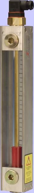
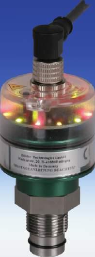
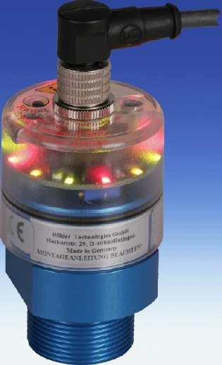
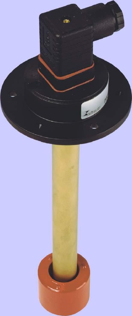
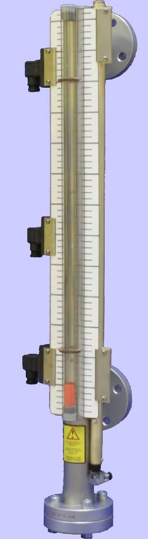
15 Nivotemp NT 61 Level and temperature switch with display NT 61D Highly visible LED display indicates the switching outputs, able to rotate 70 Up to programmable temperature switching outputs Continuous temperature signal (adjustable current or voltage) plus one programmable output Switching output adjustable as window or hysteresis Two switching outputs adjustable as frequency output (1 to 100 Hz) Menu structure based on the VDMA guidelines Min/Max memory, logbook function Level and temperature switch NT 61 Flange according to DIN 557 / Part Various connector options Up to level outputs or switching level outputs plus RTD or analog output for temperature Reliable dynamic float system Stainless steel option for temperatures up to 150 C Probe length up to 1.5 m (longer on request) Voltage up to 0 V applicable DE /01 Page 1/9
16 Technical data Nivotemp NT Basic unit max. operating pressure 1 bar operating temperature -0 C to +80 C min. spec. density of fluid 0,80 kg/dm³ with float SK 610 0,85 kg/dm³ with float SK 1 length 80, 70, 500 (standard) variable up to max weight at L=80 mm MS approx. 00 g VA approx. 00 g plus per 100 mm approx. 0 g approx. 50 g Material / design MS VA float hard PU (SK 610) SS (SK 1) immersion tube brass SS flange (DIN 557) PA PA stilling tube (option) brass stainless steel Level contacts K10 W11 function NO / NC* change over max. voltage 0 V 8 V max. current 0,5 A 0,5 A max. contact load 10 VA 0 VA min. distance of contact 0 mm 0 mm *NO= normally open / NC = normally closed at empty reservoir 65 L=80 / 70 / 500 max.1500 GI-corkgasket L= min 70 L1= min 0 first contact NT 61-MS F000009D stilling tube optional 8 with stilling tube of VA Included in delivery mounting bolts M5 (6 pieces) and GI cork-gasket last contact ø50 (MS) ø60, (VA) Temperature contact TK TM # of temp. contacts 1 max. voltage 0 V 0 V max. current,5 A A max. contact load 100 VA 100 VA O min. 0* * min. 80 with Temperature Function NC NC switching point C 50 / 60 / 70 / / 60 / 70 / 80 switching point tolerance ± K ± 5 K max. hysteresis 10 K±K 18K±5K Function NO NO switching point C 50 / 60 / 70 / / 60 / 70 / 80 switching point tolerance ± K ± 5 K max. hysteresis 10 K±K 6/5/0/5 K±5K NC = open / NO = closed at increasing temperature Other temperatures and designs with x TK contacts on request Temperature sensor RTD (Pt 100) class B, DIN EN tolerance ±0,8 C P T I O,5 min. 55* last contact * min. 80 with Temperature NT 61-VA ø Temperature transmitter KT probe element RTD (Pt 100) class B, DIN EN measuring range 0 C to +100 C operating voltage (U B ) 10-0 V DC output - 0 ma load max. ( UB - 7,5 V) / 0,0 A other measuring range on request Options stilling pipe (SSR) material same as immersion tube N A L Ø51 clearance min. Ø60 min. Ø61 with stilling pipe 60, xØ6 according to DIN 557 part DE /01 Page /9 we reserve the right to amend specifications
17 Product code for Nivotemp NT NT A B - C - Series Nivotemp NT 61 Design MS VA Connector M S6 M1 M1 C6F brass float and immersion tube stainless steel SSR = stilling tube only for double temp. contact C T (nd Temperature contact) NC NO TM50NC TM50NO =50 C TM60NC TM60NO =60 C TM70NC TM70NO =70 C TM80NC TM80NO =80 C B T1 (1st Temperature contact) NC NO TM50NC TM50NO =50 C TM60NC TM60NO =60 C TM70NC TM70NO =70 C TM80NC TM80NO =80 C O P T I Length (max mm) Variable (please specify length ) # level contacts 1- Level contact K = NC/NO W = change over A Temperature * Pt 100 = Temperature sensor (RTD) KT = Temperature transmitter TK = Temperature contact TK50NC = 50 C NC TK60NC = 60 C NC TK70NC = 70 C NC TK80NC = 80 C NC TK50NO = 50 C NO TK60NO = 60 C NO TK70NO = 70 C NO TK80NO = 80 C NO Accessories *cannot be combined with temperature contact TM Part-No. -pole Description Connecting cable M1x1, 1,5 m, elbow connector (female) and straight connector (male) Connecting cable M1x1,,0 m, elbow connector (female) and straight connector (male) Connecting cable M1x1, 5,0 m, elbow connector (female) and wire Example for order O N A L You need: You order: Level switch design MS, connector S6, length L= 550 mm, level contacts (NO/NC) and temperature contact 80 C as NC, 1st contact 100 mm NC, nd contact 70 mm NO NT 61-MS-S K-T80NC, L1=100 NC, L = 70 NO Connection M S6 M1 (base) x M1 (base) C6F pol. + PE 6 pol. + PE pol. x pol. 6 pol. + PE DIN EN DIN EN DIN EN DIN EN DIN EN max. voltage 0 V AC/DC* 0 V AC/DC* 0 V DC 0 V DC 0 V AC/DC* protection class IP 65 IP 65 IP 67** IP 67** IP 65 cable connection PG 11 M0 x 1,5 PG M1x1 58 M1x1 A B M1x F00006X F00007X F00008X F0006X F00009X Max. # of contacts Level/ Temp. contact 1xK10/1xTK xk10/1xtk 1xK10/1xTK xk10/1xtk xk10/1xtk -/- xk10/xtm -/- xk10/xtm xk10/xtm -/- 1xW11/1xTK -/- 1xW11/1xTK 1xW11/1xTK 1xW11/xTM 1xW11/xTM 1xW11/xTM Only level or x K10 x K10 x K10 x K10 x K10 1xW11 xw11 1xW11 xw11 xw11 * max. 8 V at switch contacts / **with casted connector head / other connectors on request DE /01 Page /9 we reserve the right to amend specifications
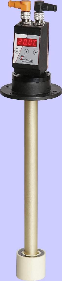
18 Technical data Nivotemp NT 61D-... Basic unit max. operating pressure 1 bar operating temperature -0 C to +80 C min. density of fluid 0.80 kg/dm³ with float SK kg/dm³ with float SK 1 standard length mm 80, 70, 500 variable up to max. 1.5 m weight MS VA at L=80 mm., approx. 00 g 00 g plus per 100 mm., approx. 0 g 50 g Material MS VA display housing PA PA float hard PU (SK 610) SS (SK 1) immersion tube brass SS flange (DIN 557) PA PA stilling tube (option) brass stainless steel Level contacts K10 max. # function NO/NC* max. voltage 0 V max. current 0.5 A max. contact load 10 VA min. distance of contact 0 mm *NO= normally open / NC = normally closed at empty reservoir Display Temperature display range -0 C to +10 C alarm range 0 C to 100 C accuracy 1% resolution 0.5 C protection class IP65 display digit 7 segment LED display operation button keypad current consumption at power up approx. 100 ma for 100 ms operating current consumption approx. 50 ma supply voltage (U B ) 10-0 V DC (nominal voltage V DC) ambient temperature -0 C to 70 C Temperature sensor RTD ( Pt 100) class B, DIN EN Included in delivery mounting bolts M5 (6 pieces) and GI cork-gasket Following temperature outputs are available: -T connector (base) x M1 -pol max. contact load 1 A PNP transistor output, x free programmable max. current PNP output 0.5 A per output short-circuit proof -1T-KT connector (base) x M1 -pol max. contact load. 1 A PNP transistor output, 1 x free programmable max. current PNP output max. 0.5 A per output short-circuit proof analog output 1x-0mA,-10 V, 0-10 V or 0-5 V load analog output max. 500 connector (base) max. contact load PNP transistor output, max. current PNP output short-circuit proof Options stilling tube DE /01 Page /9 -T 1 x M1 - pole 1 x M1-8 pole 1 A x free programmable 0.5 A per output / 1 A overall SSR Material same as immersion tube O P T I O N A L 116 L=80 / 70 / 500 max.1500 ø90 L= min 70 min.80 min. 80 L1= min 0 first contact ø7,5 ø6 1 GI corkgasket second contact top view ø second contact NT 61D-MS NT 61D-VA A M1x Ø51 Clearance min. Ø60 min. Ø61 with stilling tube B housing about 70 turnable, with stilling tube VA we reserve the right to amend specifications
19 Product code for Nivotemp NT 61D-... NT 61D- -M Series Nivotemp 61D Design MS brass VA float and immersion tube stainless steel Connector M1 Length (max mm) Variable (please specify length) SSR = stilling tube -T LED Temperature display x Temperature output -T LED Temperature display x Temperature output -1T-KT LED Temperature display 1 x Temperature output 1 x Analogue output Switch function nd contact NO = normally open NC = normally closed O P T I O N A L # level contacts 1K or K K=NO/NC Position L1=...mm 1st level contact Position L=...mm nd level contact Switch function 1st contact NO = normally open NC = normally closed Accessories Part-No. -pole Part-No. 8-pole Description Connecting cable M1x1, 1,5 m, elbow connector (female) and straight connector (male) Connecting cable M1x1,,0 m, elbow connector (female) and straight connector (male) Connecting cable M1x1, 5,0 m, elbow connector (female) and wire Example for order You need: You order: Level switch Design VA, length L= 550 mm, level contacts: 1st contact 100 mm NC, nd contact 70 mm NO, 1 temperature output, 1 analogue output, stilling tube NT 61D-VA-M1-550-K-100-NC-70-NO-1T-KT-SSR Connector x M1 (base) x pol. DIN EN max. voltage 0 V DC protection class IP 67** M1x1 housing able to rotate 70 degrees DE /01 Page 5/9 we reserve the right to amend specifications
20 Technical data Nivotemp NT 61-HT Basic unit max. operating pressure 1 bar operating temperature -0 C to 150 C (only with HT contacts) min. density of fluid 0.85 kg/dm³ with float SK 1 standard length mm 80, 70, 500 variable up to max. 1.5 m weight at L=80 mm VA approx. 950 g plus per 100 mm approx. 50 g Material float SS immersion tube SS flange SS Level contacts K10 W11 K10HT* W11HT* NO/NC change over NO/NC change over max. voltage 0 V 8 V 0 V 8 V max. current 0.5 A 0.5 A 0.5 A 0.5 A max. contact load 10 VA 0 VA 10 VA 0 VA min. distance of contact 0 mm 0 mm 0 mm 0 mm max. operating temperature 105 C 105 C 150 C 150 C *NO= normally open / NC = normally closed at empty reservoir *HT = not adjustable Included in delivery mounting bolts M5 (6 pieces) and GI cork-gasket Temperature contact TK TM # of temp. contacts 1 max. voltage 0 V 0 V max. current.5 A A max. contact load 100 VA 100 VA Function NC NC switching point in C 50 / 60 / 70 / / 60 / 70 / 80 switching point tolerance ± K ± 5 K max. hysteresis 10 K±K 18K±5K Function NO NO switching point in C 50 / 60 / 70 / / 60 / 70 / 80 switching point tolerance ± K ± 5 K max. hysteresis 10 K±K 18K±5K NO= normally open / NC = normally closed at increasing temperature) other temperatures and designs with x TK contacts on request Temperature sensor RTD (Pt 100) class B, DIN EN tolerance ±0,8 C Temperature transmitter KT probe element Pt 100 class B, DIN EN alarm range 0 C to +100 C operating voltage (U B ) 10-0 V DC output - 0 ma load max. = ( U B -75V)/0.0. A other measuring ranges on request Options stilling pipe SSR Material same as immersion tube O P T I O N S 55 L=80 / 70 / 500 max.1500 min. 55* L= min 70 GI corkgasket 90 L1= min 0 first contact last contact * min. 80 mit Temperature 7 F000090D Ø51 60,5 clearance min. Ø60 min. Ø61 with stilling pipe 8 with stilling pipe of VA 6xØ6 according to DIN 557 part DE /01 Page 6/9 we reserve the right to amend specifications
21 M1x1 Product code for Nivotemp NT NT 61-HT A B - C - Series Nivotemp NT 61 Design -HT Connector M S6 M1 M1 C6F # level contacts 1- stainless steel Length (max. 1500mm) Variable (please specify length) SSR = stilling tube Only for double temp. contact C T (nd Temperature contact) NC NO TM50NC TM50NO =50 C TM60NC TM60NO =60 C TM70NC TM70NO =70 C TM80NC TM80NO =80 C B T1 (1st Temperature contact) NC NO TM50NC TM50NO =50 C TM60NC TM60NO =60 C TM70NC TM70NO =70 C TM80NC TM80NO =80 C A Temperature * Pt 100 = Temperature sensor (RTD) KT = Temperature transmitter TK = Temperature contact TK50NC = 50 C NC TK60NC = 60 C NC TK70NC = 70 C NC TK80NC = 80 C NC O P T I O N A Level contact K =NO/NC K-HT =NO/NC W = change over W-HT = change over TK50NO = 50 C NO TK60NO = 60 C NO TK70NO = 70 C NO TK80NO = 80 C NO *cannot be combined with temperature contact TM L Accessories Part-No. -pole Description Connecting cable M1x1, 1.5 m, elbow connector (female) and straight connector (male) Connecting cable M1x1,. 0m, elbow connector (female) and straight connector (male) Connecting cable M1x1, 5.0 m, elbow connector (female) and wire Example for order You need: Level switch, connector M, length L= 550 mm, level contacts (NO/NC) 1st contact 100 mm NC, nd contact 70 mm NO, temperature sensor, stilling tube You order: NT 61HT-M-550--K-HT-Pt 100-SSR, L1=100 NC, L = 70 NO Connector M S6 M1 (base) x M1 (base) C6F pol. + PE 6 pol. + PE pol. x pol. 6 pol. + PE DIN EN DIN EN DIN EN DIN EN DIN EN max. voltage 0 V AC/DC* 0 V AC/DC* 0 V DC 0 V DC 0 V AC/DC* protection class IP 65 IP 65 IP 67** IP 67** IP 65 cable connection PG 11 M0 x 1,5 PG M1x1 M1x F000091X F000095X F00009X F000X F00009X max. # of contacts level/ temp. contact 1xK10/1xTK xk10/1xtk 1xK10/1xTK xk10/1xtk xk10/1xtk -/- xk10/xtm -/- xk10/xtm xk10/xtm -/- 1xW11/1xTK -/- 1xW11/1xTK 1xW11/1xTK 1xW11/xTM 1xW11/xTM 1xW11/xTM only level or x K10 x K10 x K10 x K10 x K10 1xW11 xw11 1xW11 xw11 xw11 * max. 8 V at change over contacts / **with casted connector head / other connectors on request DE /01 Page 7/9 we reserve the right to amend specifications
22 Standard pin assignment NT 61 and NT 61-HT Connector M S6/C6 M1 x M1 (base) (base) A B 1 only level contact(s) Type K10 only level contact(s) Type W11 level contact(s) Type K10 and temperature level contact(s) Type K10 and Pt 100 (RTD) level contact(s) Type W11 and temperature level contact(s) Type W11 and Pt 100 (RTD) level contact(s) Type K10 and Temp. contacts level contact Type W11 and Temp. contacts L1 L1 L L L L L PE L 5 6 PE 1 L1 PE 1 L1 L1 L L L TK/KT PE 5 6 TK / KT/ PE L 5 PE L1 1 L L 5 6 PT PE 1 L1 5 5 TK/KT PT L1 1 L TM 1 TM 5 6 PE 1 L1 TM 1 TM 5 6 PE 6 6 PE 1 L1 6 PE 1 L1 L1 TK/KT L1 1 A L L 1 B L 1 L1 A 1 L B L1 1 A L L 1 B TK / KT L1 1 A L 1 B PT 1 L1 A 1 B TK / KT 1 L1 A 1 B PT L1 1 A L TM 1 B TM 1 1 L1 A TM 1 TM 1 B TK/TM = Thermo contact KT = Temperature transmitter PT = Temperature sensor Pt 100 (RTD) other assignment on request DE /01 Page 8/9 we reserve the right to amend specifications
23 Standard pin assignment NT 61D A B Type NT 61D-T level contact(s) x Temperature output Type NT 61D-1T-KT level contact(s) 1 x Temperature output 1 x Analogue output Type NT 61D-T level contact(s) x Temperature output Connector A = Level 1 L1 1 L L1 1 L L1 1 L Connector B = Temperature 1 Pt 100 (RTD) Display unit 1 +VDC GND Pt 100 (RTD) Display unit 1 +VDC GND Display unit 1+VDC GND OUT OUT 1 5 OUT T1 (PNP) T1 (PNP) 6 OUT T (PNP) Analog out Pt 100 (RTD) Note: If the switching output is measured with high-impedance measuring equipment or if the frequency output is used, connect a 10 k resistor between output and ground to avoid faulty measurements. DE /01 Page 9/9 we reserve the right to amend specifications
24 Nivotemp 61-0-WW The entrance of water into fluid power or lubrication systems significantly reduces the life of oil and causes damage to other components used in the systems. The most reliable method of detecting water in oil is to measure the interface level between water and oil when the water is separated. This Nivotemp version is equipped with an additional float which rises in water but sinks in oil. The reservoir has to be equipped with a small cavity in the bottom and the contact tube of the Nivotemp reaches down to the lowest point of the cavity. When a volume of approx. 0 ml of free water accumulates in the cavity the float will rise and actuate a contact. The signal can either be used to open a drain valve, drain the water off, or just to set an alarm. An easily installed prefabricated sump is available as an accessory. With water alarm function Reliable physical measuring system Easy installation Independent of oil chemistry Up to four adjustable level contacts Cable connector standard DE /01
25 Technical Data Operating pressure max. 1 bar Operating temperature max. 80 C Density of fluid min. 0,8 kg/dm³ Density of oil max kg/dm³ Material: Float SK 610 for level control hard PU Float WW for water alarm PPH Switch tube brass Flange PA 6 Weight L=500 mm 750 g Level contacts / K10 W water alarm contacts - - K6 W7 Function *NC / NO change over *NC / NO change over Distance of contact, min. 0 mm 0 mm fixed fixed Max. voltage 0 V 8 V 0 V 0 V Max. current 0,5 A 0,5 A 1 A 1 A Contact load 10 VA 0 VA 50 VA 0 VA 6,5 L=max.150 Dimensions (mm) GI-cork sealing L=min.70 min.0 0 L1=min.0 First contact Last contact Water alarmcontact F00000D Float SK 610 for level control 6 Float WW for water alarm *NC=normally closed / NO=normally open, all figures at empty reservoir Connectors S6 xm1 (socket) C6F (Other connectors 6 pol. + PE pol / pol. 6 pol. + PE upon request) DIN 651 DIN ,5 90 Protection class IP 65 IP 67** IP 65 Cable gland M0x1,5 PG7** PG11 **with plug fixed 7 9 ø55 Clearance=min.ø60 M1x1 M1x A B 100 ø90 ø7 F00007X F0006X Max. no of contacts xk10 + 1xK6 xk10 + 1xK6 xk10 + 1xK6 or xw11 + 1xK6 1xW11 + 1xK6 xw11 + 1xK6 or xk10 + 1xW7 xk10 + 1xW7 xk10 + 1xW7 or 1xW11 + 1xW7 1xW11 + 1xW7 1xW11 + 1xW7 Max. voltage 0 V AC/DC V DC 0 V AC/DC 8 V with change 8 V with change over contacts over contacts Installation example Asmall collecting basin is welded to the floor of the reservoir at the deepest appropriate point (see also installation principle). We recommend to use the prefab sump but you are free to provide a solution yourself. To make the unit effective the volume of the collecting basin should be as small as possible. Therefore please use the recommended dimensions. Water F00009X Installation Principle Oil F00001D 6xø6 according to DIN557 part 6x bolts M5x16 Welded collecting basin with connection G/. Drain cock (not supplied with collecting sump) min.ø65 (inside diameter of collecting basin) Ordering information Basic version (without level- and water alarm contacts) Part-no. Description Connector Length Nivotemp 61-0-WW-S6-level contacts-water alarm contacts S6 L (max. 150 mm) Nivotemp 61-0-WW-xM1-level contacts-water alarm contacts xm1 L (max. 150 mm) Nivotemp 61-0-WW-C6F-level contacts-water alarm contacts C6F L (max. 150 mm) Part-no. Description Number of contacts Type Length Level contact K10 see table connectors NC / NO L1 (, L, L, L) Level contact W11 see table connectors change over L1 (, L, L, L) Water alarm contact K6 1 NC / NO fixed Water alarm contact W7 1 change over fixed Acessories: collecting sump (with connection G/, include plug), dimensions: ø70/,6 x height=1mm Example: You need: Nivotemp (Basic): Connector: type S6; length L= 580 mm, st 1 contact 100 mm NC, Level contacts: nd contact 500 mm NO, Water alarm contact: 1, normally closed (NC) min.10 You order: Nivotemp 61-0-WW-S6-xK10-1xK6, L= x level contacts K10, L1=100 NC, L = 500 NO x water alarm contact K6, NC We reserve the right to amend specifications.
26
27

28
29 Nivotemp NT 6 Level and temperature switch with display NT6D Highly visible LED display indicates the switching outputs, able to rotate 70 Menu structure based on the VDMA guidelines Two wireless, adjustable level contacts Up to four programmable temperature switching outputs Continuous temperature signal (adjustable current or voltage) plus one programmable output Switching output adjustable as window or hysteresis Two switching outputs adjustable as frequency output (1 to 100 Hz) Min/Max memory, logbook function Level and temperature switch NT 6 Wireless, adjustable level contacts Flange according to DIN 557 part Multiple connector options Up to four level contacts or two outputs for level plus RTD or analogue output for temperature Reliable dynamic float system Stainless steel option for temperatures up to 150 C Probe length up to 1.5 m (longer on request) V standard, 0 V on request DE /015 Page 1/6
30 Technical data NT 6 Basic unit max. operating pressure 1 bar operating temperature -0 C to +80 C min. density of fluid 0.80 kg/dm³ with float SK kg/dm³ with float SK 1 length mm 80, 70, 500 Material / Design MS VA float hard PU (SK 610) (SK 1) immersion tube brass flange (DIN 557) PA PA 65 GI-corkgasket L1= min 0 first contact F000009D 8 with VA with stilling tube Level contacts K W function NO/NC* change over max. # max. voltage 0 V 0 V max. current 0.5 A 0.5 A max. contact load 10 VA 0 VA min. distance of contact 0 mm 0 mm *NO = normally open / NC = normally closed included in delivery mounting bolts M5 (6 pieces) and GI cork-gasket L=80 / 70 / 500 L= min 70 min. 60 last contact stilling tube optional ø50 (MS) ø60. (VA) Temperature contact max. voltage max. current max. contact load TK 0 V.5 A 100 VA.5 last contact ø Function NC NO switching point in C 50 / 60 / 70 / / 60 / 70 / 80 switching point tolerance ± K ± 5 K max. hysteresis 10 K±K 10K±K NO = normally open / NC = normally closed (figures at increasing temperature) O P min. 55* *min. 80 with Temperature Ø51,5 57 Temperature sensor Pt 100 (RTD), class B, DIN EN tolerance ± 0.8 C Temperature transmitter KT probe element Pt 100 (RTD), class B, DIN EN measuring range 0 C to +100 C operating voltage ( UB) 10-0 V DC output - 0 ma load max. = ( U B V) / 0.0 A other measurement ranges on request Option SSR - stilling tube material same as immersion tube T I O N S 90 7 Installation dimension min. Ø60 min. Ø61 with stilling tube 60 6xØ6 according to DIN 557 / Part Connector M S6 M1 (base) x M1 (base) pol. + PE 6 pol. + PE pol. x pol. DIN EN DIN EN max. voltage 0 V AC/DC 0 V AC/DC 0 V DC 0 V DC protection class IP 65 IP 65 IP 67** IP 67** cable connection PG 11 M0 x M1x1 M1x1 M1x A B F00006X max. # of contacts - level / temp. contact 1xK/1xTK xk/1xtk 1xK/1xTK xk/1xtk -/- 1xW/1xTK -/- 1xW/1xTK F00007X - level only x K x K x K 1xW xw 1xW **with casted connector head / other connectors on request F00008X F0006X DE /015 Page /6 we reserve the right to amend specifications
31 Series Nivotemp NT 6 Product code for NT 6 NT 6- Design MS VA Connector M S6 M1 M1 Length (mm) brass float and immersion tube stainless steel # of level contacts 1- Level contact K = NO/NC W = change over Accessories SSR = stilling tube Temperature Pt 100 = Temperature sensor (RTD) KT = Temperature transmitter TK = Temperature contact T50NO = 50 C T60NO = 60 C T70NO = 70 C T80NO = 80 C T50NC = 50 C T60NC = 60 C T70NC = 70 C T80NC = 80 C Example for order You need: Level switch with flange, brass, connector S6, length L= 500 mm, x level contacts and temperature contact TK80 as NC, 1st contact 100 mm) NC, nd contact 0 mm NO You order: NT 6-MS-S6/ K -T80NC, L1=100 NC, L = 0 NO Standard pin assignment NT 6 Connector M S6 M1 (base) x M1 (base) A B 1 only level contact(s) Type K L1 1 L PE L1 1 L L L 5 L1 1 L 6 PE only level contact(s) Type W Level contact(s) Type K and temperature Level contact(s) Type W and temperature 1 L1 PE 1 L1 L1 L L L TK/KT PE 5 6 TK/KT/PT PE L 5 PE 1 L1 5 6 TK/KT/PT PE 6 1 L1 L1 TK / KT L1 1 A L 1 B TK / KT / PT 1 L1 A 1 B TK/KT/PT TK = Thermo contact KT = Temperature transmitter PT = Temperature sensor Pt 100 (RTD) other assignments on request DE /015 Page /6 we reserve the right to amend specifications
32 Technical data NT 6D Basic unit max. operating pressure 1 bar operating temperature -0 C to +80 C min. density of fluid 0.80 kg/dm³, float SK kg/dm³, float SK 1 lengths mm 80, 70, M1x1 Housing able to rotate 70 degrees Material / Design MS VA display housing PA PA float hard PU (SK 610) (SK 1) immersion tube brass flange (DIN 557) PA PA SSR (option) brass stainless steel Level contacts K max. # function NO / NC* max. voltage 0 V max. current 0.5 A max. contact load 10 VA min. distance of contact 0 mm *NO = normally open / NC = normally closed included in the delivery mounting bolts M5 (6 pieces) and GI cork-gasket Display temperature display range -0 C to +10 C alarm indicator range 0 C to 100 C accuracy 1% resolution 0.5 C protection class IP65 display digit 7 segment LED display operation button keypad current consumption at power up approx. 100 ma for 100 ms operating current consumption approx. 50 ma supply voltage (U B ) 10-0 V DC (nominal voltage V DC) ambient temperature -0 C to +70 C L L min.60 L1=min.0.5 distance of contacts = min. 0 5 F SK610 Ø51 (MS) Ø60. (VA) GI-cork gasket SSR stilling tube with support ring Temperature sensor: Pt 100 (RTD) class B, DIN EN The following temperature outputs are available: -T connector (base) x M1 -pol max. contact load 1 A PNP transistor output, x free programmable max. current PNP output 0.5 A per output 1T-KT connector (base) x M1 -pol max. contact load 1 A PNP transistor output, 1 x free programmable max. current PNP output 0.5 A per output analog output 1 x -0 ma, -10 V, 0-10 V or 0-5 V load analog output max. 500 O P T I min. 60* top view: last contact *min. 80 with Temperature Ø51,5 57 Clearance min. Ø60 min. Ø61 with stilling tube connector (base) max. contact load PNP transistor output, max. current PNP output -T 1 x M1 - pole 1 x M1-8 pole 1A x free programmable 0.5 A per output / 1 A overall O N S Ø90 Ø7 6xØ6 Option stilling tube SSR Material same as immersion tube 60 DE /015 Page /6 we reserve the right to amend specificationsn
33 1 5 6 Series Nivotemp Design MS VA Connector x M1 Length brass float / immersion tube stainless steel # of level contacts 1K or K K = NO/NC Position L1=...mm 1st level contact NT 6D Product code for NT 6D NT 6D- -M1 -T LED Temperature display x Temperature output -T LED Temperature display x Temperature output -1T-KT LED Temperature display 1xTemperature output 1 x Analogue output Switch function nd contact NO/NC Position L=...mm nd level contact Switch function 1st contact NO/NC Accessories: Part No. Description Connecting cable M1x1, -pol., 1.5 m, elbow connector (female) and straight connector (male) Connecting cable M1x1, -pol.,. 0m, elbow connector (female) and straight connector (male) Connecting cable M1x1, -pol., 5.0 m, elbow connector (female) and wire Connecting cable M1x1, 8-pol., 1.5 m, elbow connector (female) and straight connector (male) Connecting cable M1x1, 8 -pol.,. 0m, elbow connector (female) and straight connector (male) Connecting cable M1x1, 8-pol., 5.0 m, elbow connector (female) and wire Example for order You need: Level switch with flange, design MS, connector S6, length L= 500 mm, x level contacts; 1st contact 100 mm NC, nd contact 0 mm NO, with temperature display and x programmable temperature output You order: NT 6D-MS-M1/500-K-100NC-0NO-T Standard pin assignment NT 6D A B Type NT 6D-T Level contact(s) x Temperature output Type NT 6D-1T-KT Level contact(s) 1 x Temperature output 1 x Analogue output Type NT 6D-T Level contact(s) x Temperature output Connector A = level 1 L1 1 L L1 1 L L1 1 L Connector B = temperature 1 Pt 100 (RTD) Display unit 1 +VDC GND Pt 100 (RTD) Display unit 1 +VDC GND Display unit 1 +VDC GND OUT OUT 1 5 OUT T1 (PNP) T1 (PNP) 6 OUT T (PNP) Analog out Pt 100 (RTD) Note: If the switching output is measured with high-impedance measuring equipment or if the frequency output is used, connect a 10 k resistor between output and ground to avoid faulty measurements DE /015 Page 5/6 we reserve the right to amend specifications
34 The EasyJust System 10 (adjustability) contact strip with cm scale Thermo element TK/PT/KT changing contact function NC/NO by turning the contacts 180 wireless (bistable) level contacts function: NC or NO Using adjustable level contacts allows the application of standardized immersion tubes in oil tanks of different sizes and geometrical shapes. The switching points are changeable to the requirement of the individual application at any time without purchasing a specific level switch. This facilitates design and logistics for the users and OEMs. The Easy Just System is based on a wireless structure of the contacts. The contacts are designed of closed and color coded housings. They are positioned on a printed circuit board with gold plated contacts. The colors are used for the coding of the different contacts and assure the allocation of the connector s assignments. The contacts function (NC or NO) is determined by the 180 rotation on the printed circuit board. An adjusted temperature switch (bi-metal, NO or NC), a Pt 100 (RTD) or a -0 ma transmitter is fixed at the lower end of the printed circuit board, depending on the chosen option for the temperature monitoring. DE /015 Page 6/6 we reserve the right to amend specifications
35
36
37
38
39
40

41
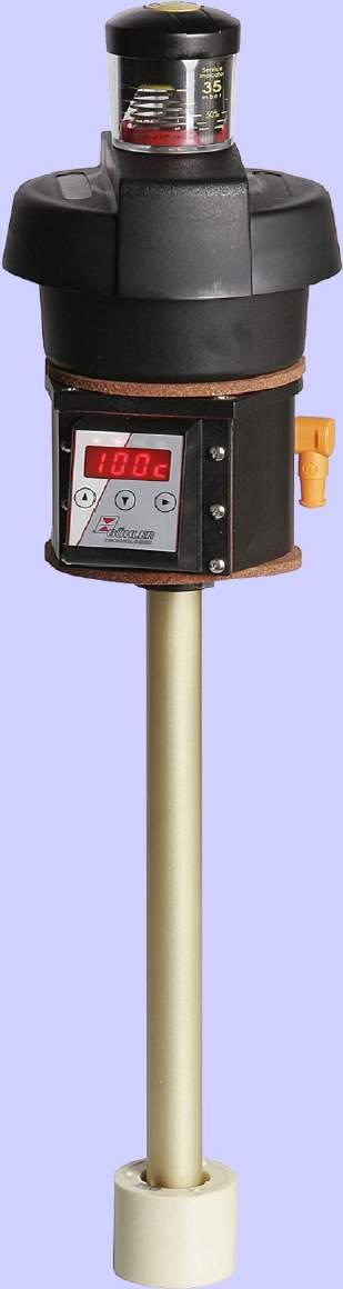
42 Nivovent NV 71 Level and temperature switch with display NV 71D Highly visible LED display indicates the switching outputs High performance air breather with replaceable element Optional air breather clogging indicator Up to programmable temperature switching outputs Continuous temperature signal (adjustable current or voltage) plus one programmable switching output Switching output adjustable as window or hysteresis Two switching outputs adjustable as frequency output (1 to 100 Hz) Menu structure based on the VDMA guidelines Min/Max memory, logbook function Level and temperature switch NV 71 Flange according to DIN 557 Part High performance air breather with replaceable element Optional air breather clogging indicator Multiple connector options Up to level contacts or switching outputs for level plus RTD or analogue output for temperature Reliable dynamic float system Probe length up to 1.5 m (longer on request) Up to 0 V applicable DE /01 Page 1/6
43 X Technical data NV 71 Basic units max. operating pressure 1 bar operating temperature -0 C to +80 C min. density of fluid 0.80 kg/dm³ / SK kg/dm³ / SK 1 lengths mm 80, 70, 500 (standard) variable up to max MS VA weight at L=80 mm approx. 790 g 870 g add. per 100 mm 0 g 50 g Air breather filter HY Type Hydac BF 7 grade of filtration µm accessories filling protection cover - not applicable for filling adapter - Material / Design MS VA* float hard PU SK 610 SK 1 immersion tube brass flange/ filter housing PA PA SSR (option) brass stainless steel Level contacts K10 W11 function NO / NC change over max. voltage 0 V 8 V max. current 0.5 A 0.5 A max. contact load 10 VA 0 VA min. contact distance 0 mm 0 mm NO = normally open / NC = normally closed at empty reservoir Temperature contact TK TM # of temp. contacts 1 max. voltage 0 V 0 V max. current.5 A A max. contact load 100 VA 100 VA Function NC NO switching point C 50/60/70/80 50/60/70/80 tolerance ± K ±5 K max. hysteresis 10 K ± K 6/5/0/5 K ±5 K NC= normally open / NO = normally closed (at low temperature) other temperatures & designs with x TK contacst on request Temperature sensor Pt 100 class B, DIN EN tolerance ± 0.8 C Temperature transmitter KT sensor element Pt 100 class B, DIN EN measurement range 0 C to +100 C operating voltage (U B) 10-0 V DC output - 0 ma load max. (UB V) / 0.0 A other measurement ranges on request Options/ Accessories (see details on page 6) VS visual clogging indicator for the air breather BFA** filling adapter incl. ribbed flange with sieve insert: SSR** stilling tube with support ring and filling adapter MT for Multiterminal MTS for Multiterminal including stilling tube FCT Fluidcontrolterminal * not available in combination with option FCT ** not available in combination with option FCT, MT and MTS O P T I O N A L Flange picture according to DIN 557/part Design with options 6xØ6 Basic version 50 VS clogging indicator NBR gasket NBR gasket x = min. 55* x = min. 0* Float SK 610 for NV 71-MS L=L-x ma 90 SK610 Float SK 1 for NV 71-VA last contact 65 L = max L = min L1 = min. 0 first contact last contact,5 SK610 6 GI-corkgasket GI-corkgasket L 1 65 L=min.90 L1=min.50 X 5 first contact last contact,5 90 SK610 5 BFA filling adapter SSR stilling tube with support ring and filling adapter DE /01 Page /6 Ø51 * min. 80 with temperature
44 Series Nivovent NV 71-HY Design MS VA* Connector M S6 M1 M1 Lengths (max mm) other lengths (please specify) # level contacts 1- brass float and immersion tube stainless steel Product code for NV 71 NV 71-HY- A B C 50% Service Indicator 50 mbar Options / Accessories VS = clogging indicator BFA** SSR** MT MTS FCT = filling adapter = stilling tube with filling adapter = for Multiterminal = for Multiterminal incl. stilling tube = Fluidcontrolterminal Only for double temp. contact C T (nd Temperature contact) Opener Closer TM50NC TM50NO =50 C TM60NC TM60NO =60 C TM70NC TM70NO =70 C TM80NC TM80NO =80 C B T1 (1st Temperature contact) NC NO TM50NC TM50NO =50 C TM60NC TM60NO =60 C TM70NC TM70NO =70 C TM80NC TM80NO =80 C A Temperature *** Level contact Pt 100 (RTD) = Temperature sensor K = NC/NO KT = Temperature transmitter W = change over TK = Temperature contact TK50NC = 50 C (NC) TK60 NC = 60 C (NC) * not available in combination with option FCT TK70 NC = 70 C (NC) ** not available in combination with option FCT, MT and MTS TK80 NC = 80 C (NC) ***not for combination with temperature contact TM TK50 NO = 50 C (NO) TK60 NO = 60 C (NO) TK70 NO = 70 C (NO) TK80 NO = 80 C (NO) Accessories Part-No. -pole Description Connecting cable M1x1, 1,5 m, elbow connector (female) and straight connector (male) Connecting cable M1x1,,0 m, elbow connector (female) and straight connector (male) Connecting cable M1x1, 5,0 m, elbow connector (female) and wire Example for order You need: Level switch brass with air breather and clogging indicator, length L=500 mm, level contacts and temperature contact TK 80 C as opener, 1st contact: 100 mm NC, nd contact: 0 mm NO O P T I O N A L You order: NV 71-HY-MS-S6-500-K -TK80NC-VA, L1=100 NC, L = 0 NO Connector M (DIN650) S6 (DIN651) M1 (base) x M1 (base) pol. + PE 6 pol. + PE pol. pol./ pol. max. voltage 0 VAC/DC* 0 VAC/DC* 0 V DC 0 V DC protection class IP 65 IP 65 IP67** IP67** cable connection PG 11 M0x1, M1x max. # of contacts Level / Temp. contact 1 x K10 / 1xTK xk10/ 1xTK 1xK10/ 1xTK xk10/ 1xTK -/- xk10/xtm -/- xk10/xtm -/- 1xW11/1xTK -/- 1xW11/1xTK 1xW11/xTM 1xW11/xTM M1x1 F0006X 51 M1x1 level only x K10 x K10 x K10 x K10 or 1xW11 xw11 1xW11 xw11 * max. 8V for change over contact / **with casted connector head / other connectors on request DE /01 Page /6 we reserve the right to amend specifications
45 Technical Data NV 71D Basic units max. operating pressure 1 bar operating temperature -0 C to +80 C min. density of fluid 0.80 kg/dm³ / SK kg/dm³ / SK 1 lengths mm 80, 70, 500 (standard) variable to max MS VA weight at 80 mm app. 85 g 910 g add. per 100 mm app. 0 g 50 g Air breather filter HY Typ Hydac BF 7 grade of filtration µm accessories filling protective cover - not applicable for filling adapter - Material / Design MS VA* display housing PA PA float hard PU SK 610 SK 1 immersion tube brass flange/ filter housing PA PA Level contacts K10 max. quantity function NC / NO max. voltage 0 V max. current 0.5 A max. contact load 10 VA min. contact distance 0 mm * NC= normally open / NO = normally closed at empty reservoir Display Temperature display range -0 C to +10 C Alarm range 0 C to 100 C accuracy 1% resolution 0.5 C protection class IP 65 display digit, 7 segment LED operation button keypad current consumption at power up approx. 100 ma for 100 ms operating current consumption approx. 50 ma supply voltage (U B ) 10 V to 0 V DC (nominal V DC) ambient temperature -0 C to +70 C Temperature sensor Pt 100 class B, DIN EN Flange picture according to DIN 557/part Basic version The following temperature outputs are available: -T connector (base) x M1 -pol max. contact load 1 A PNP transistor output, x free programmable max. current PNP output 0.5 A per output sustained short-circuit proof -1T-KT connector (base) x M1 -pol max. contact load 1 A PNP transistor output, 1 x free programmable max. Current PNP output 0.5 A per output analogue output 1x-0mA,-10 V, 0-10 V or 0-5 V max. load analogue output 500 -T connector (base) 1 x M1 - pol. 1 x M1-8 pol. max. contact load 1 A PNP transistor output, x free programmable max. current PNP output** sustained short-circuit proof 0.5 A per output Options/ Accessories (see details on page 6) VS visual clogging indicator for the air breather BFA** filling adapter incl. ribbed flange with sieve insert SSR** stilling tube with support ring and filling adapter MT for Multiterminal MTS for Multiterminal including stilling tube FCT Fluidcontrolterminal * not available in combination with option FCT ** not available in combination with option FCT, MT and MTS 50 Design with options VS clogging indicator O P T I O N A L min. 80 L ,5 6xø6 Float for NV 71D-VA L = max mm NBR gasket L=min L1=min. 0 first contact last contact SK610 6 display and control unit GI-corkgasket GI-corkgasket NBR gasket L 1 65 L=min. 90 L1=min first contact last contact SK BFA filling adapter SSR stilling tube with centered disc and filling adapter Ø51 min.80,5 min. 80,5 5 DE /01 Page /6 we reserve the right to amend specifications
46 1 5 6 Product code for NV 71D NV 71D-HY- -M1 Series Nivovent NV 71D-HY Design MS brass VA* float and immersion tube stainless steel Connector x M1 S6 50% Service Indicator 50 mbar Options / Accessories VS = clogging indicator BFA** SSR** MT MTS FCT = filling adapter = stilling tube with filling adapter = for Multiterminal = for Multiterminal incl. stilling tube = Fluidcontrolterminal O P Length (max mm) Variable (please quote) -T LED temperature indicator x temperature outputs T # level contacts 1K or K K = NO/NC -T LED temperature indicator x temperature outputs I Position L1=...mm 1st level contact Switch function 1st contact NO = normally open NC = normally closed -1T-KT LED temperature indicator 1 x temperature output 1 x analogue output -0 ma Switch function nd contact NO = normally open NC = normally closed O N * not available in combination with option FCT ** not available in combination with option FCT, MT and MTS Position L=...mm nd level contact Accessories Part-No. -pole Part-No. 8-pole Description Connecting cable M1x1, 1.5 m, elbow connector (female) and straight connector (male) Connecting cable M1x1,. 0m, elbow connector (female) and straight connector (male) Connecting cable M1x1, 5.0 m, elbow connector (female) and wire Example for order You need: Level switch stainless steel with air breather and clogging indicator, length L= 500 mm, level contacts, 1st contact: 100 mm NC, nd contact: 0 mm NO, temperature outputs You order: Connector xm1 A Connector A: Level Connector B: Temperature NV 71D-HY-VA-M1-500-K-100 NC-0 NO-T-VA B 1 L1 1 L 1 +VDC GND L1 1 L L1 1 L Display Display 1 1 OUT 1 unit unit 5 OUT 5 7 Pt 100 (RTD) Standard pin assignment NV 71D Type NV 71D-T Level contact(s) x Temperature outputs T1 (PNP) T (PNP) Type NV 71D-1T-KT Level contact(s) 1 x Temperature output 1 x Analogue output Pt 100 (RTD) 1 +VDC GND T1 (PNP) Analog out Type NV 71D-T Level contact(s) x Temperature output Display unit 1 +VDC GND OUT 6 OUT Pt100 (RTD) 6 8 Connector S6 Display unit 1 +VDC GND T1 (PNP) T (PNP) 5 L1 6 (L) Display unit 1 +VDC GND T1 (PNP) Temp. -0 ma 5 L1 6 (L) Pt 100 (RTD) Pt 100 (RTD) DE /01 Page 5/6 Note: If the switching output is measured with high-impedance measuring equipment or if the frequency output is used, connect a 10 k resistor between output and ground to avoid faulty measurements. we reserve the right to amend specifications
47 Standard pin assignment NV 71 Connector M (DIN EN ) S6 (DIN EN ) M1 (base) x M1 (base) 1 A B only level contact(s) Type K10 L1 1 L PE L1 1 L L L 5 6 PE L1 1 L L1 1 A L L 1 B L only level contact(s) Type W11 level contact(s) Type K10 and temperature level contact(s) Type K10 and Pt 100 (RTD) level contact(s) Type W11 and temperature level contact(s) Type W11 and Pt100 (RTD) level contact(s) Type K10 and temp. contacts level contact Type W11 and temp. contacts 1 L1 PE 1 L1 L1 L L L TK/KT PE 5 6 TK/KT PE L 5 PE L1 1 L L 5 6 PT PE 1 L1 5 5 TK/KT PT L1 1 L TM 1 TM 5 6 PE 1 L1 TM 1 TM 5 6 PE 6 6 PE 1 L1 6 PE 1 L1 L1 TK/KT 1 L1 A 1 L B L1 1 A L L 1 B TK/KT L1 1 A L 1 B PT 1 L1 A 1 B TK / KT 1 L1 A 1 B PT L1 1 A L TM 1 B TM 1 1 L1 A TM 1 B TM 1 TK/TM = Thermo switch KT = temperature transmitter PT = temperature sensor Pt 100 (RTD) other configurations on request Options / Accessories VS visual clogging indicator for the air breather: analog underpressure indicator, display range 0.5 bar. BFA* filling adapter incl. ribbed flange with sieve insert: this option allows that small oil quantities can be filled via the air breather housing. Therefore the corresponding housing is equipped with that version. SSR* stilling tube with support ring and filling adapter: This includes the option stilling tube as well as the option for filling as the BFA. The stilling tube is made of the same material as the requested immersion tube (MS/VA). MT for integration into Multiterminal: The basic unit will be mounted to the Multiterminal. For specification we refer to data sheet DA MTS for integration into Multiterminal including stilling tube: in addition to the basic unit, a stilling tube with support ring is mounted to the Multiterminal. FCT Fluidcontrolterminal: The Fluidcontrolterminal ( FCT) will be mounted to the basic product. For specification we refer to data sheet DA * not available in combination with option FCT, MT and MTS DE /01 Page 6/6 we reserve the right to amend specifications
48
49
50

51
52 Nivovent NV 7 Level and temperature switch with display NV 7D Highly visible LED display indicates the switching outputs High performance air breather with replaceable filter element Optional air breather clogging indicator Two wireless, variable level switches Up to programmable temperature switching outputs Continuous temperature signal, (adjustable current or voltage ) plus one programmable output Switching output adjustable as window or hysteresis Two switching outputs adjustable as frequency output (1 to 100 Hz) Menu structure based on VDMA guidelines Min/Max memory, logbook function Level and temperature switch NV 7 Wireless, variable level switches Flange according to DIN 557 Part High performance air breather with replaceable filter element Optional air breather clogging indicator Multiple connector options Up to level contacts or switching outputs for level plus bimetal, RTD or analog output for temperature Reliable dynamic float system V standard, 0 V on request DE /015 Page 1/6
53 Technical data NV 7 Basic unit max. operating pressure 1 bar operating temperature -0 C to +80 C min. density of fluid 0,80 kg/dm³ float SK 610 0,85 kg/dm³ float SK 1 standard length (in mm) 80, 70, 500 (standard) weight MS VA* at L=80 mm ca. 800 g ca. 900 g additional per 100 mm ca. 0 g ca. 50 g Air breather filter HY Type Hydac BF 7 grade of filter µm Accessories filling protective cover (not applicable for filling adapter) Material /Design MS VA* float hard PU SK 610 SK 1 immersion tube brass flange / filter housing PA PA Level contacts K W max. quantity function NO / NC change over max. voltage 0 V 0 V max. current 0,5 A 0,5 A max. contact load 10 VA 0 VA min. distance of contact 0 mm 0 mm NO=<normally open / NC=normally closed, all figures at empty reservoir Temperature contact max. voltage max. current max. contact load Flange picture according to DIN 557/part TK 0 V,5 A 100 VA 6x 6 81 NBR gasket O P T. Basic version Function NC NO switching point C 50/60/70/80 50/60/70/80 switching point tolerance ± K ± K max. hysteresis 10 K ± K 10 K ± K NC = normally open / NO = normally closed (all figures at increasing temperature) Temperature sensor RTD Pt100 class B, DIN EN tolerance ±0,8 C Temperature transmitter KT sensor element RTD Pt100 class B, DIN EN measurement range 0 C to +100 C operating voltage (U B) 10-0 V DC output - 0 ma load max. = (UB -7,5 V) / 0,0A other measurement ranges on request Options/ Accessories (see details on page 6) VS visual clogging indicator for the breather BFA** filling adapter incl. ribbed flange with sieve insert: SSR** stilling tube with support ring and filling adapter MT for Multiterminal MTS for Multiterminal including stilling tube FCT Fluidcontrolterminal * not available in combination with the option FCT ** not available in combination with the option FCT, MT and MTS 50 NBR gasket Design with options VS clogging indicator BFA filling adapter O P T I O N A L min NV 7-VA last contact 65 L = 80 / 70 / 500 mm L=min L1=min.0 first contact last contact SK610 6 GI-corkgasket GI-corkgasket L 1 65 L=min.90 L1=min.50 5 SK SSR stilling tube with support ring and filling adapter Ø51,5 min.60,5 min.60 5 Connector M (DIN EN ) S6 (DIN EN ) M1 (base) x M1 (base)*** pol. + PE 6 pol. + PE pol. pol./ pol. max. voltage 0 VAC/DC 0 VAC/DC 0 V DC 0 V DC protection class IP 65 IP 65 IP67** IP67** cable connection PG 11 M0x1,5 M1x M1x1 max. quantity of contacts level/ temp.-contact 1xK/ 1xTK xk/ 1xTK 1xK/ 1xTK xk/ 1xTK -/- 1xW/1xTK -/- 1xW/1xTK level only x K x K x K or 1xW xw 1xW ** with casted connector head *** Connectors electrically isolated / on request other connectors DE /015 Page /6 we reserve the right to amend specifications M1x1 F0006X 51
54 Series Nivotemp NV 7-HY Connector M S6 M1 M1 Quantity of level contacts 1- Level contact K = NC / NO W = change over NV 7-HY- Design MS brass VA* float and immersion tube stainless steel Length (mm) Product code for NV 7 * not available in combination with option FCT Accessories ** not available in combination with the option FCT, MT and MTS Part-No. -pole Description Connecting cable M1x1, 1,5 m, elbow connector (female) and straight connector (male) Connecting cable M1x1,,0 m, elbow connector (female) and straight connector (male) Connecting cable M1x1, 5,0 m, elbow connector (female) and wire Example for order You need: Level switch with breather, clogging indicator, length L= 500 mm, level contacts, temperature contact TK, 80 C as NC, 1st contact 100 mm NC, nd contact 0 mm NO You order: NV 7-HY-MS-S K-TK80NC-VS 100 NC, 0 NO 50% Service Indicator 50 mbar Accessories VS = clogging indicator Optionen BFA** = filling adapter SSR** = stilling tube with filling adapter MT = for Multiterminal MTS = for Multiterminal incl. stilling tube FCT = Fluidcontrolterminal Temperature Pt 100 = Temperature sensor (RTD) KT = Temperature transmitter TK = Temperature contact T50NO = 50 C NO T60NO = 60 C NO T70NO = 70 C NO T80NO = 80 C NO T50NC = 50 C NC T60NC = 60 C NC T70NC = 70 C NC T80NC = 80 C NC O P T I O N A L only level contact(s) Type K L1 1 L PE Standard pin assignment NV 7 Connector M S6 M1 ( base ) x M1 ( base ) L1 1 L L L 5 6 PE L1 1 L only level contact(s) Type W level contact(s) Type K and temperature 1 L1 PE 1 L1 L1 L L L TK/KT PE 5 6 TK/KT/PT PE L 5 6 PE 1 L1 L1 TK / KT L1 1 A L 1 B TK/KT/PT level contact(s) Type W and temperature 1 L1 5 6 TK/KT/PT PE 1 L1 A 1 B TK/KTPT TK = Thermo contact KT = Temperature transmitter PT = Temperature sensor Pt 100 (RTD) other assignments on request DE /015 Page /6 we reserve the right to amend specifications
55 Technical data x 6 NV 7D Basic unit max. operating pressure 1 bar operating temperature -0 C to +80 C min. density of fluid 0,80 kg/dm³ float SK 610 0,85 kg/dm³ float SK 1 standard length (mm) 80, 70, 500 weight at L=80 mm approx. MS 850 g VA* 950 g add. per 100 mm approx. 0 g 50 g Air breather filter HY Typ Hydac BF 7 grade of filtration µm Accessories filling protective cover ( not applicable for filling adapter) Material / Design MS VA* display housing PA PA float hard PU SK 610 SK 1 immersion tube brass flange / filter housing PA PA SSR (option) brass stainless steel Level contacts K max. quantity function NO / NC max. voltage 0 V max. current 0,5 A max. contact load 10 VA min. distance of contact 0 mm NO= normally open / NC = normally closed, all figures at empty reservoir Display temperature display range -0 C to +10 C ( F to 8 F) alarm range setting 0 C to 100 C ( F to 178 F) accuracy 1% resolution 0,5 C (1 F) protection class IP65 display digit 7 segment LED operation button keypad last contact min. 60 Flange picture according to 557/part NV 7-VA L = 80 / 70 / 500 mm Basic version NBR gasket L=min L1=min.0 first contact last contact SK610 6 current consumption at power up operating current consumption approx. 100 ma for 100 ms approx. 50 ma supply voltage (U B ) 10-0 V DC (nominal voltage V DC) ambient temperature -0 C to +70 C temperature sensor RTD class B; DIN EN Following temperature outputs are available: -T connector (base) x M1 -pol max. contact load 1A PNP transistor output, x free programmable max. current PNP output 0,5 A per output short-circuit proof -1T-KT connector (base) x M1 -pol max. contact load 1 A PNP transistor output, 1 x free programmable max. current PNP output 0,5 A per output O short-circuit proof analogue output 1x-0mA,-10 V, 0-10 V or 0-5 V P max. load analogue output 500 -T T connector (base) 1 x M1 - pol. 1 x M1-8 pol. max. contact load 1 A I PNP transistor output, x free programmable max. current PNP output max. 0,5 A per output short-circuit proof O Options/ Accessories (see details on page 6) VS visual clogging indicator for the air breather BFA** filling adapter incl. ribbed flange with filter insert: SSR** stilling tube with support ring and filling adapter MT for Multiterminal MTS for Multiterminal including stilling tube FCT Fluidcontrolterminal * not available in combination with option FCT * not available in combination with option FCT and MT/MTS display and control unit GI-corkgasket GI-corkgasket 50 L 1 65 Design with options NBR gasket L=min.90 L1=min SK610 VS clogging indicator BFA filling adapter SSR stilling tube with support ring and filling adapter N Ø51,5 min.60,5 min.60,5 5 DE /015 Page /6 we reserve the right to amend specifications
56 1 5 6 Series Nivovent NV 7D-HY NV 7D-HY- Design MS brass VA* float and immersion tube VA Connector M1 S6 Length (mm, max. 1500) Quantity level contacts 1K or K K=NO/NC Position L1=...mm 1st level contact Switch function 1. contact NO = normally open NC = normally closed * not available in combination with option FCT ** not available in combination with the option FCT, MT and MTS Product code for NV 7D 50% Service Indicator 50 mbar Options BFA** SSR** MT MTS FCT Accessories VS = clogging indicator = filling adapter = stilling tube with filling adapter = for Multiterminal = for Multiterminal incl. stilling tube = fluidcontrolterminal -T LED temperature display x temperature output -T LED temperature display x temperature output -1T-KT LED temperature display 1 x temperature output 1 x analogue output -0 ma Switch function. contact NO = normally open NC = normally closed O P T I O N A L Position L=...mm Accessories nd level contact Part-No. -pole Part-No. 8-pole Description Connecting cable M1x1, 1,5 m, elbow connector (female) and straight connector (male) Connecting cable M1x1,,0 m, elbow connector (female) and straight connector (male) Connecting cable M1x1, 5,0 m, elbow connector (female) and wire Example for order You need: Level switch and breather, clogging indicator, length L= 500 mm, level contacts, temperature contact TK 80 C as NC, 1st contact 100 mm NC, nd contact 0 mm NO You order: NV 7-HY-MS-S6 500-K -TK80NC-VS-100-NC-0 NO Connector xm1 A Connector A Level B 1 Standard pin assingment NV 7D Type NV 7D-T Level contact(s) x Temperature output L1 1 L Type NV 7D-1T-KT Level contact(s) 1 x Temperature output 1 x Analogue output L1 1 L Type NV 7D-T Level contact(s) x Temperature output L1 1 L Connector B Temperature 1 Pt 100 (RTD) Display unit 1 +VDC GND T1 (PNP) T (PNP) PT100 (RTD) Display unit 1 +VDC GND T1 (PNP) Analog out Display unit Pt 100 (RTD) 1 +VDC GND OUT OUT 1 5 OUT 6 OUT Connector S6 Display unit 1 +VDC GND T1 (PNP) T (PNP) 5 L1 6 (L) Display unit 1 +VDC GND T1 (PNP) Temp. -0 ma 5 L1 6 (L) Pt 100 (RTD) Pt 100 (RTD) DE /015 Page 5/6 we reserve the right to amend specifications
57 Details about options and accessories: VS visual clogging indicator for the air breather: analog underpressure indicator, display range 0.5 bar. BFA* filling adapter incl. ribbed flange with sieve insert: this option allows that small oil quantities can be filled via the air breather housing. Therefore the corresponding housing is equipped with that version. SSR* stilling tube with support ring and filling adapter: This includes the option stilling tube as well as the option for filling as the BFA. The stilling tube is made of the same material as the requested immersion tube (MS/VA). MT for integration into Multiterminal: The basic unit will be mounted to the Multiterminal. For specification we refer to data sheet DE MTS for integration into Multiterminal including stilling tube: in addition to the basic unit, a stilling tube with support ring is mounted to the Multiterminal. FCT Fluidcontrolterminal: The Fluidcontrolterminal ( FCT) will be mounted to the basic product. For specification we refer to data sheet DE * not available in combination with option FCT and MT/MTS The EasyJust System 10 (adjustability) contact strip with cm-scale thermo element TK/PT/KT changing of contact function NO / NC due to turning the contacts at 180 wireless (bistable) level contacts function: closer (NC) or opener (NO) Using adjustable level contacts allows the application of standardized immersion tubes in oil tanks of different sizes and geometrical shapes. The switching points are changeable to the requirement of the individual application at any time without purchasing a specific level switch. This facilitates design and logistics for the users and OEMs. The Easy Just System is based on a wireless structure of the contacts. The contacts are designed of closed and color coded housings. They are positioned on a printed circuit board with gold plated contacts. The colors are used for the coding of the different contacts and assure the allocation of the connector s assignments. The contacts function (NO or NC) is determined by the 180 rotation on the printed circuit board. An adjusted temperature switch (bi-metal, NO or NC), a Pt 100 (RTD) or a -0 ma transmitter is fixed at the lower end of the printed circuit board, depending on the chosen option for the temperature monitoring. DE /015 Page 6/6
58
59

60
61
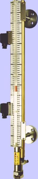
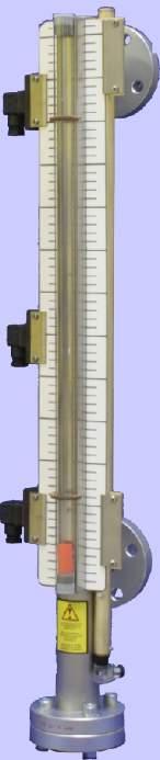
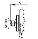
62 HD NS 50-AM-G1-V / HD NS 60-AM-G1-V Level switch HD NS for external installation Visual and electric monitoring of liquid level Pressure range up to 60 bar TÜV approved Lengths up to 5000 mm (longer on request) Adjustable level contacts Optional analog output -0 ma Visual indicator with scale Robust design meets industrial standards Float with dynamic buoyancy Specials upon request DE /01 Page 1/
63 Type Betriebsüberdruck bar Betriebstemp. C Kunden-Nr. D-00 RATINGEN WEST-GERMANY TEL.(010)980-0 Nr. Inhalt L. Baujahr Technical data HD NS 50-AM-G1-V Basic data max. operating pressure 50 bar max. operating temperature 50 C min. density of fluid 0.80 kg/dm³ L1 max mm weight at L1=500 mm approx. 15 kg weight L mm approx kg on request longer lengths Material float SK597 compact plastic standpipe upper end piece steel bottom end piece steel check valve vent valve sight glass PC vent valve upper check valve lower check valve 0 G1 F00010D 0 85 port air L=L1+58 optional frame with mounting bracket Connector upper check valve lower check valve G1 G1 appropriate level contacts see on page Option transducer tube -K continuous level measurement principle reed contact resolution 5 or 10 mm operating voltage (U B ) 10-0 V DC (nominal voltage V DC) output - 0 ma load max. = (U V) / 0.0 A Note: This level switch includes TÜV approval. Tested according to Pressure Equipment Directive 97//EC (Module G) Accessories Part No. Description mounting bracket heavy series SPAL frame for ground mounting of the level switch with mounting bracket SPAL bolts x DIN59-M1x00 with nuts B O P T I O N min. 600 x ø16 min. 1 L port fluid x00 50x50 Bühler 100 G1 90 stub for removal of the float leave 50 mm of installation space optional mounting bracket O P T. Option -K5 -K10 Product code for HD NS 50-AM-G1-V HD NS 50-AM-G1-V- transducer tube continuous, resolution 5 mm continuous, resolution 10 mm -SK597 / Length L1 =...mm Example for order You need: Level switch for external mounting, operating pressure 50 bar, measuring length L1 = 00 mm, with continuous level output, resolution 10 mm and change over contacts (see page ) You order: HD NS 50-AM-G1-V-K5-SK597 / L1 = 00 x part no contact MKS 1/W DE /01 Page /
64 Type Bühler Betriebsüberdruck bar Betriebstemp. C Kunden-Nr. D-00 RATINGEN WEST-GERMANY TEL.(010)980-0 Nr. Inhalt L. Baujahr Technical data HD NS 60-AM-G1-V Basic data max. operating pressure 60 bar max. operating temperature 50 C min. spec. density of fluid 0.80 kg/dm³ L1 max mm weight at L1=500 mm approx. 0 kg weight L mm approx. 1.0 kg on request longer lengths vent valve upper check valve 0 G port air Material float SK 597 compact plastic standpipe topmost end piece steel bottom end piece steel check valve vent valve sight glass PC lower check valve F00010D L=L1+58 optional frame with mounting bracket Connector upper check valve lower check valve G1 G1 appropriate level contacts see page Option transducer tube -K continuous level measurement principle reed contact resolution 5 or 10 mm operating voltage (U B ) 10-0 V DC (nominal voltage V DC) output - 0 ma load max.. (U V) / 0.0 A HD NS 60-AM-G1-V- B Note: These level switches are delivered with TÜV approval. Tested according to Pressure Equipment Directive 97//EC (Module G) Accessories Part No. Description mounting bracket heavy series SPAL 606, frame for ground mounting of the level switch with mounting bracket SPAL 606, bolts x DIN59-M1x00 with nuts O P T. Option -K5 -K10 -SK597 / min. 600 x ø16 min. 1 L Product code for HD NS 60-AM-G1-V transducer tube continuous, resolution 5 mm continuous, resolution 10 mm O P T I O N port fluid 50 Length L1 =...mm 0 00x00 50x G1 90 stub for removal of the float leave 50 mm of installation space optional mounting bracket Example for order You need: Level switch for external mounting, operating pressure max. 60 bar, measuring length L1 = 00 mm, with change over contacts (see page ) You order: HD NS 60-AM-G1-V-SK597 / L1=00; x part no contact MKS 1/W DE /01 Page /
65 Contacts for NS..-AM Type function MKS-1/K NC / NO max. voltage 0 V AC/DC max. current 1 A max. contact load 50 VA connector M (DIN EN ) pol.+pe protection class IP 65 Part No Pin assignment (contact position at empty reservoir) mounting left mounting right 1 PE 1 PE Type function MKS-/K x NC / NO max. voltage 0 V AC/DC max. current 1 A max. contact load 50 VA connector S6 (DIN EN ) 6pol.+PE protection class Part No. IP PE PE Type function MKS-1/W change over max. voltage 0 V AC/DC max. current 1 A max. contact load 50 VA connector M (DIN EN ) pol.+pe protection class Part No. IP PE 1 PE Type function MKS-1/W-L V change over with LED max. voltage V DC max. current 1 A max. contact load 5 VA connector S6 (DIN EN ) 6pol.+PE protection class Part No. IP LED red 1 +V GND 5 6 PE LED red 1 +V GND 5 6 PE other contacts on request For operations in areas with strong vibrations we suggest to use contacts MKS-1/K and MKS-K. When mounting a transducer tube with continuous output signals you have to keep in mind that the mounting of contacts is possible only on the left side. Pin assignment for AM-K with connector S -0 ma 1 +V DC level out MKS 1/K MKS 1/W MKS /K MKS 1/W-LV DE /01 Page / we reserve the right to amend specifications
66 Pressure transmitter Pressotronik 70 Characteristics Pressure ratings up to 600 bar Compact and robust design Stainless steel measuring cell Pressure measuring cell with pressure sensor, welded seal-free, no elastomer seal High bursting safety plug connection options DE /01 Page 1/
67 Technical Data Pressure transmitter Pressotronik 70 Pressure ranges 0-10 bar 0-5 bar bar 0-50 bar 0-00 bar bar other pressure ranges available upon request Medium Pressure connection with FPM profile gasket Overload higher values upon request Burst pressure Liquids, gasses and refrigerants, incl. ammonia G ¼ external thread, DIN 85 form E x terminal value at 10 to 600 bar (but max bar) 6 x terminal value (max. 500 bar) Material Housing Connector holder Materials in contact with media Pressure connection Measuring element Stainless steel 1.0 / AISI 16L Polyarylamide 50 % GF VO Stainless steel 1.0 / AISI 16L Stainless steel Temperature Medium C Ambient temperature C Storage C Response time Load cycle Supply voltage (U b) Power input Output signal Burden Ω Reverse polarity safety <= ms / typical 1 ms <= 100 Hz 7 - V DC <= ma - 0 ma, wire = (Ub-7 V) / 0,0 A Short circuit and reverse polarity safety (each connection to each with max. voltage) Electrical connection M (IP 65) M1 (IP 67) / Delivered without connector head Accuracy (test conditions: 5 C, 5 % rf, supply VDC) Characteristic (*1) Resolution Thermal behaviour (*) % FS % FS % FS/10K ± 0, 0,1 ± 0, Long-term stability according to IEC EN % FS ± 0,5 *1: Typical max. 0,5 % FS *: C Mounting position Weight any approx. 90 g Tests / approvals Electromagnetic compatibility CE compliant per EN and shock per IEC g, 11 ms, Half-sine curve, all 6 directions, free fall from 1 m onto concrete (6x) Bump per IEC g over 6 ms, 1000x all directions Vibration per IEC g, Hz, Hz with amplitude ± 15 mm, 1 octave/minute all directions, 50 continuous loads DE /01 Page /
68 Product code for Pressotronik 70 PT 70 Series Pressure range 0-10 bar 0-5 bar bar 0-50 bar 0-00 bar bar Plug connection M M1 M (DIN EN A) pol.+pe IP 65 M1 (base) pol. IP 67 Plug connection 1 Pin assignment -wire 1 +VDC -0 ma out PE* 1 +VDC -0 ma out Ø 18,8 ± 0,1 1 58,5 6 ~88 Ø 18,8 ± 0, ,7 Scale drawing G 1/ Ø G 1/ Ø,1 * not connected to the transmitter housing. Accessory: Part-no. Description Connecting cable M1x1, 1,5 m, angular coupling and straight plug Connecting cable M1x1,,0 m, angular coupling and straight plug Connecting cable M1x1, 5,0 m, angular coupling and strands DE /01 Page / we reserve the right to amend specifications
, broken wire detection, respective 5 LEDs for status indication on")
69 Switch Amplifier for Level- / Temperature Switch - Atex A variation of switch amplifiers is available for the control of level and temperature in hydraulic applications. Single channel switch amplifier types KFD/KFA for intrinsically safe circuits with one or two alarm relays (change over contact), broken wire detection, respective 5 LEDs for status indication on power, alarm and broken wire. The devices must be installed outside the hazardous area! Rail mounting according to EN Intrinsically safe inputs Approved by ATEX, FM, UL, CSA DE /01
70 Technical Data Controller for use with trigger contact ; output one or two change over contacts Power supply: Model, 1-channel: part no: Model, -channel: part no: 0-0 V DC 10,5-16 V AC 07-5 V AC 5-65Hz 5-65Hz KFD -SR-Ex 1.W KFA 5-SR-Ex 1.W KFA 6-SR-Ex 1.W KFD -SR-Ex.W KFA 5-SR-Ex.W KFA 6-SR-Ex.W General Data Instrinsically safe acc. to EN broken wire detection approved by UL CSA yes II(1) GD [Ex ia] IIC Class I, Groups A, B, C, D Class II, Groups E, F, G Class I, Div. 1, Groups A, B, C, D Class II, Div. 1, Groups E, F, G Output Switch power output change over (non fail-safe) 0 V AC, A cos > V cc, A resistive load Ambient temperature C Protection class IP 0 Dimensions WxHxD (in mm) 0 x 118 x 115 we reserve the right to amend specification


71 Circular pumps BFP Low noise emission High vol. efficiency Good suction performance Built-in bell housing Gerotor principle Not susceptible to contamination DE /015 page 1 / 7


72 Circular pumps BFP Introduction and description Why gerotor? Numerous applications in hydraulic and lubrication systems just require the circulation of the fluid. In such cases low noise emissions and low pressure ripples are more important than highly efficient transmission of energy. The gerotor is the ideal principle for such applications. The displacement mechanism consists of the inner and the outer rotor. The number of teeth of the inner rotor is always one less than the outer rotor. The rotation of the gerotor generates chambers of changing volumes between the inner and outer rotor. The variation follow a sinus curve, resulting in a very steady surge. Due to the inevitable displacement, the flow rate generated is proportional to the rotation speed. Inlet Outlet When we designed the BFP series we specifically selected the number of teeth and the width of the gerotors so the pumps have the smallest possible physical dimensions, low weight and minimal loss in efficiency. The low relative speed between the internal and external gear make the pumps extremely durable and smooth. The internal design of the pumps further reduces the flow paths and ensures good suction performance. Why complete pump units? Every additional component increases the overall installed size of the systems, inevitably increasing the space requirement and typically also the costs. One requirement in developing the BFP series was therefore to keep them as short and compact as possible. On the BFP 8 to 0 models the gerotor is driven directly by the motor shaft. On the larger BFP 60 and 90 pumps the motor shaft is built into a special coupling. The coupling runs in oil and is therefore optimally lubricated and cooled. Planning information Installation site requirements Ensure adequate ventilation. The pumps are mounted in the installation site using four screws Electrical connection The electrical connection must be made by an appropriately trained electrician! Observe the voltage and mains frequency! Fusing must comply with applicable standards! Please note the direction of rotation of the motor when connecting. Hydraulic connection Full utilisation of the high capacity of the pumps requires care when configuring the intake line. This is a very important factor with use in lubricating systems. These are typically filled with higher viscosity oils and must operate reliably in a large temperature range. Although the tremendous increase in viscosity in low temperatures are frequently overlooked. For applications where the parameters are within critical ranges, we recommend calculating the precise expected pressure loss in the suction pipe or using an adequate size (never smaller than the existing pump suction port!). The suction and pressure pipe must be installed free from tension and vibration. When using hoses, pay particular attention to the appropriate reinforcement on the suction side so the hose cannot collapse due to the negative pressure. We reserve the right to amend specification. DE /015
73 Circular pumps BFP If the pump unit is not already intended for an off-line filter, the oil should have an average purity class of 15/11 per ISO 06 or better. This is essential in significantly extending the service life of all components. Do not continuously exceed the recommended suction pressure of the pumps. Some situations may require priming the suction pipe prior to first start-up. Avoid possible leaks in the circuit to prevent environmental damages. If necessary, use e.g. an oil pan. Technical data Technical data Pump housing: Gerotor: anodised and impregnated cast aluminium sintered steel Operating fluids: mineral oils per DIN 515 Operating oil temperature: Seal: max. 80 C (higher temperatures on request) Perbunan (NBR) Viton (FPM) available on request Ambient temperature: -15 C to +0 C Electric motors Voltage / frequency: 0 / 00 V - 50 Hz ± 5 % 76 / 80 V - 60 Hz ± 5 % Thermal stability: Class of insulation F, utilisation per class B Design: Protection class: on request: The motors comply with standards IEC 600, IEC 6007, IEC three-phase asynchronous squirrel-cage induction motor totally enclosed, fan cooled IP55 other voltages higher motor powers for higher viscosities UL- or CSA-approved motors higher protection type Please also observe the operating manual for the motor! All pumps are supplied with cable gland inside the motor terminal box. The total length and height of the pump may vary by motor make. Pump selection information: When selecting the pump model, choose the motor output according to the oil viscosity to be used. Motor output information refers to the maximum oil viscosity at maximum operating pressure. The BFP 5 to BFP 0 are also available as a special version with a 6 bar internal bypass valve for protection. This does not change the dimensions. Installation information: The pump head of all pumps can be mounted turned in 90 increments to align with the line routing. Please note the offset from the centre of the motor. The connection threads are manufactured to ISO 8. The screw-in surfaces are finished and suitable for the use of soft seals. We recommend using screwed plugs per ISO Please note: Especially note the dimension of the suction pipe. The cross-sections should not be smaller than specified. In most cases, loud noise indicates the cross-section was reduced too much. Please refer to the notices in the operating instructions. DE /015 We reserve the right to amend specification.
74 Circular pumps BFP BFP 5 / BFP 8 / BFP 15 BFP kW BFP kW BFP kW BFP kW BFP kW Item number IE IE IE IE Motor power 0.55 kw 0.75 kw 0.75 kw 1.1 kw 1.5 kw Max. oil viscosity 1500 cst 1500 cst 00 cst 1500 cst 000 cst At max. working pressure 10 bar 10 bar 10 bar 10 bar 10 bar Number of poles 6 Max. current consumption (00V / 50Hz)* approx. 1.8 A approx..1 A approx..1 A approx..7 A approx..5 A Nominal delivery volume* 5.8 cm ³ /U 5.8 cm ³ /U 11.7 cm ³ /U 11.7 cm ³ /U 11.7 cm ³ /U 5.5 l/min 8 l/min 16 l/min 16 l/min 16 l/min Suction side connection G1/-DN16 G//DN0 G1 1/-DN G1 1/-DN G1 1/-DN Pressure side connection G/8-DN1 G1/-DN16 G1-DN5 G1-DN5 G1-DN5 Suction pressure for all models temporarily up to Acoustic power per ISO 7* -0. bar -0. bar -0. bar -0. bar -0. bar -0.6 bar 5 db(a) 56 db(a) 59 db(a) 59 db(a) 59 db(a) Weight 10.8 kg 10.8 kg 10.9 kg 1. kg 16. kg Dimensions A B C D E * For 60 Hz versions please multiply the delivery volume by a factor of 1.. The acoustic emission increases by approx. db. D E Inlet Outlet A B 100 C ø Flow rate We reserve the right to amend specification. DE /015
75 Circular pumps BFP BFP 0 / BFP 0 BFP kW BFP kW BFP0--1.5kW BFP0--1.1kW BFP0--1.5kW Item number 70075IE 70110IE 70150IE 70110IE 70150IE Motor power 0.75 kw 1.1 kw 1.5 kw 1.1 kw 1.5 kw Max. oil viscosity 100 cst 00 cst 1000 cst 100 cst 700 cst At max. working pressure 6 bar 8 bar 10 bar 6 bar 8 bar Number of poles Max. current consumption (00V / 50Hz)* approx..1 A approx..7 A approx..5 A approx..7 A approx..5 A Nominal delivery volume* 0. cm ³ /U 0. cm ³ /U 0. cm ³ /U 0.6 cm ³ /U 0.6 cm ³ /U 9 l/min 9 l/min 9 l/min l/min l/min Suction side connection G1 1/-DN G1 1/-DN G1 1/-DN G1 1/-DN G1 1/-DN Pressure side connection G1-DN5 G1-DN5 G1-DN5 G1-DN5 G1-DN5 Suction pressure for all models temporarily up to Acoustic power per ISO 7* -0. bar -0. bar -0. bar -0. bar -0. bar -0.6 bar 61 db(a) 61 db(a) 61 db(a) 6 db(a) 6 db(a) Weight 11 kg 1. kg 16. kg 1.7 kg 16.7 kg Dimensions A B C * For 60 Hz versions please multiply the delivery volume by a factor of 1.. The acoustic emission increases by approx. db Inlet Outlet A 100 C B ø Flow rate DE /015 We reserve the right to amend specification. 5
76 Circular pumps BFP BFP 60 BFP kw BFP 60--.kW BFP 60--kW BFP 60--kW Item number IE 7600IE 76000IE 76000IE Motor power 1.5 kw. kw kw kw Max. oil viscosity 100 cst 00 cst 800 cst 1500 cst At max. working pressure 6 bar 8 bar 10 bar 8 bar Number of poles Max. current consumption (00 V / 50 Hz)* approx..6 A approx..9 A approx. 6. A approx. 8. A Nominal delivery volume* 0.8 cm ³ /U 0.8 cm ³ /U 0.8 cm ³ /U 0.8 cm ³ /U 58 l/min 58 l/min 58 l/min 58 l/min Suction side connection G1 1/-DN0 G1 1/-DN0 G1 1/-DN0 G1 1/-DN0 Pressure side connection G1 1/-DN G1 1/-DN G1 1/-DN G1 1/-DN Suction pressure for all models temporarily up to -0. bar -0. bar -0. bar -0. bar -0.6 bar Acoustic power per ISO 7* 6 db(a) 6 db(a) 6 db(a) 6 db(a) Weight 17. kg. kg. kg.6 kg Dimensions A B C D E F G H J K * For 60 Hz versions please multiply the delivery volume by a factor of 1.. The acoustic emission increases by approx. db. B 7 6 Inlet Outlet E F A D C øk G H Flow rate 6 We reserve the right to amend specification. DE /015
77 Circular pumps BFP BFP 90 BFP kW BFP kw BFP 90--kW BFP 90--kW Item number IE 7900IE 79000IE 79000IE Motor power 1.5 kw. kw kw kw Max. oil viscosity 6 cst 100 cst 00 cst 1000 cst At max. working pressure 6 bar 8 bar 8 bar 8 bar Number of poles Max. current consumption (00 V / 50 Hz)* approx..6 A approx..9 A approx. 6. A approx. 8. A Nominal delivery volume* 61. cm ³ /U 61. cm ³ /U 61. cm ³ /U 61. cm ³ /U 88 l/min 88 l/min 88 l/min 88 l/min Suction side connection G1 1/-DN0 G1 1/-DN0 G1 1/-DN0 G1 1/-DN0 Pressure side connection G1 1/-DN G1 1/-DN G1 1/-DN G1 1/-DN Suction pressure for all models temporarily up to -0. bar -0. bar -0. bar -0. bar -0.6 bar Acoustic power per ISO 7* 65 db(a) 65 db(a) 65 db(a) 65 db(a) Weight 19 kg.8 kg.8 kg. kg Dimensions A B C D E F G H J K * For 60 Hz versions please multiply the delivery volume by a factor of 1.. The acoustic emission increases by approx. db. B Inlet 7 6 Outlet E F A D C øk G H Flow rate DE /015 We reserve the right to amend specification. 7


78 Off-line filter / cooler unit BKF Compact, space-saving design DIN filter elements Easy installation Easy element replacement Efficient plate heat exchanger DE /015 page 1 / 8
79 Off-line filter / cooler unit BKF Introduction and description Why off-line aggregates? Depending on the system configuration there are operating conditions (variable capacity pumps, back-flow peaks, etc.), which significantly limit the effectiveness of full flow filtration or even render it completely ineffective. In addition, quite practical considerations such as installing a cooler with is required anyway or the option of system-independent operation may argue for an off-line aggregate. Why Bühler? When we developed the BKF series, we incorporated our years of experience in designing and selling water coolers and filters. Special attention was paid to a compact design. By using standard filter elements in this respect we are not bound to a specific filter supplier. Together with a well-known manufacturer, Bühler implemented these findings in a comprehensive product line customised for the requirements in fluid control. Use the data in this leaflet to determine a suitable cooler for your application. If our standard range of products does not includes the right system for your application, we will gladly develop a custom solution for you. BKF 18/0 A low-noise gerotor pump resistant to dirt is integrated into the very compact baseplate. The drive motor and filter housing are arranged vertically and parallel to save space. The suction and pressure line are positioned so they can be routed straight down into the reservoir. This minimises the installation work. Since the baseplate is also equipped with front connections, the aggregate can be cased next to the reservoir. The aggregate has a built-in pressure limiting valve. NG 50 DIN elements are used as filter elements. BKF 60/90 A compact, space-saving design was also realised in this series. Motor, pump and filter housing are combined into one unit and mounted to a frame for side mounting. The DIN filter element with NG 00 removes to the top for changing. Planning information Installation site requirements Ensure adequate ventilation. The aggregates are mounted in the installation site using four screws Electrical connection The electrical connection must be made by an appropriately trained electrician! Observe the voltage and mains frequency! Fusing must comply with applicable standards! Please note the direction of rotation of the motor when connecting. Hydraulic connection Full utilisation of the high capacity of the aggregates requires care when configuring the intake line. This is a very important factor with use in lubricating systems. These are typically filled with higher viscosity oils and must operate reliably in a large temperature range. Although the tremendous increase in viscosity in low temperatures are frequently overlooked. For applications where the parameters are within critical ranges, we recommend calculating the precise expected pressure loss in the suction pipe or using an adequate size (never smaller than the existing pump suction port!). The suction and pressure pipe must be installed free from tension and vibration. When using hoses, pay particular attention to the appropriate reinforcement on the suction side so the hose cannot collapse due to the negative pressure. Do not continuously exceed the recommended suction pressure of the pumps. Some situations may require priming the suction pipe prior to first start-up. Avoid possible leaks in the circuit to prevent environmental damages. If necessary, use e.g. an oil pan. We reserve the right to amend specification. DE /015
80 Off-line filter / cooler unit BKF Technical data Technical data Pump housing: Gerotor: Hydraulic screw joint: Anodised and impregnated cast aluminium Sintered steel Galvanised steel Operating fluids: Mineral oils per DIN 515 Operating oil temperature: Seal: max. 80 C (higher temperatures on request) Perbunan (NBR) or Viton (FPM) on request Ambient temperature: -0 C to +0 C Electric motors Voltage / frequency: 0 / 00 V - 50 Hz ± 5 % 76 / 80 V - 60 Hz ± 5 % Thermal stability: Class of insulation F, utilisation per Class B Design: Protection class: on request: The motors comply with standards IEC 600, IEC 6007, IEC three-phase asynchronous squirrel-cage induction motor totally enclosed, fan cooled IP55 other voltages higher motor power for higher viscosities UL- or CSA-approved motors higher protection class Please also observe the operating manual for the motor! All motors are supplied with cable gland inside the terminal box. The total height of the aggregate may vary by motor make. Installation information: The connection threads are manufactured to ISO 8. The screw-in surfaces are finished and suitable for the use of soft seals. We recommend using screwed plugs per ISO Please note: Especially note the dimension of the suction pipe. The cross-sections should not be smaller than specified. In most cases, loud noise indicates the cross-section was reduced too much. Please refer to the notices in the operating instructions. Wiring diagrams Accessories Wiring diagram BKF 18/0 Wiring diagram BKF 60/90 Accessories Optional: manometer or pressure gauge Optional: manometer or pressure gauge Water IN / OUT Inlet Output Inlet Output DE /015 We reserve the right to amend specification.
81 Off-line filter / cooler unit BKF BKF 18 / BKF 0 Heat exchanger mount View A Oil OUT Water IN Screw-in connection Water OUT Contamination indicator (optional) Plate heat exchanger Aggregate mounting diagram Note: When installing next to the oil reservoir please not the intake! When determining the bores on the reservoir be sure the contamination indicators remains visible! Type: BKF BKF Motor power: 0.55 kw 0.75 kw Number of poles: 6 Power input (00 V 50 Hz): ~ 1.7 A ~ A Suction lift: m m Filter element pressure limit: 6 bar 6 bar Display pressure contamination indicator:. bar. bar Suction side connection: G/ / G1 G/ / G1 Suction side hose: DN 0 / DN 5 DN 0 / DN 5 Pressure side connection: G/ G/ Pressure side hose: DN 0 DN 0 Suction pressure: For all aggregates briefly: -0. bar -0. bar -0.6 bar Connection "Water IN": G1/ G1/ Connection Water OUT : G1/ G1/ Flow rate: 18 L/min 8 L/min Max. feed pressure: 6 bar 6 bar Weight: approx. 0 kg approx. 0 kg We reserve the right to amend specification. DE /015
82 Off-line filter / cooler unit BKF BKF 60 / BKF 90 Oil OUT Water IN G1 E-Motor.kW IE -pole / assy. 100 Filter housing NG00 Plate heat exchanger Water OUT Oil IN Mounting bores x Ø10 Plug for drain bore Filter housing Note: When installing next to the oil reservoir please not the intake! When determining the bores on the reservoir be sure the contamination indicators remains visible! Contamination indicator (optional) Type: BKF BKF Motor power:. kw.8 kw Number of poles: Power input (00 V 50 Hz): ~.6 A ~.6 A Suction lift: m m Filter element pressure limit:.5 bar.5 bar Display pressure contamination indicator:. bar. bar Suction side connection: G1 1/ G1 1/ Suction side hose: DN 0 DN 0 Pressure side connection: G1 1/ G1 1/ Pressure side hose: DN DN Suction pressure: For all aggregates briefly: -0. bar -0. bar -0.6 bar Connection "Water IN": G1 G1 Connection Water OUT : G1 G1 Flow rate: 57 L/min 86 L/min max. oil viscosity: 00 cst 100 cst at max. operating pressure 8 bar 8 bar Weight: approx. 8 kg approx. 8 kg DE /015 We reserve the right to amend specification. 5

83 Off-line filter / cooler unit BKF Cooling capacity curves BKF 18 BKF 0 BKF 60 BKF 90 6 We reserve the right to amend specification. DE /015
84 Off-line filter / cooler unit BKF Selecting the filter fineness Determining the contamination class per ISO 06 > µm >6 µm >1 µm System type Highly reliable control systems susceptible to sludge accumulations; laboratory or aerospace High performance servo systems and high pressure systems with a long life; e.g. aviation, machine tool, etc High-quality, reliable systems: general machinery construction General machinery construction and vehicles; moderate pressure, moderate capacity 19 1 General machinery construction and vehicles; low-pressure systems in heavy machinery construction Recommend filter retention rate Recommended element 1- Sm-N -5 Sm-x Sm-x Sm-x Sm-x Sm-x5 / Mic 10 DE /015 We reserve the right to amend specification. 7
85 Off-line filter / cooler unit BKF Ordering instructions Off-line filters Item no. Type Description BKF 18 without contamination indicator NBR BKF 18 mechanical contamination indicator NBR 9010 BKF 18 electric contamination indicator NBR 9000 BKF 0 without contamination indicator NBR 9010 BKF 0 mechanical contamination indicator NBR 900 BKF 0 electric contamination indicator NBR BKF 60 without contamination indicator NBR BKF 60 mechanical contamination indicator NBR 9060 BKF 60 electric contamination indicator NBR BKF 90 without contamination indicator NBR BKF 90 mechanical contamination indicator NBR 9090 BKF 90 electric contamination indicator NBR Filter elements For type Item no. Description Filter fineness Purity class ** BKF 18 / BKF N 050 DN µm 1/ N 050 DN 6 6 µm 1/ N 050 DN µm 15/11 BKF 60 / BKF N 000 DN µm 1/ N 000 DN 6 6 µm 1/ N 000 DN µm 15/11 ** Purity classes achievable per ISO 06 for BKF 18/0 at V = 00 L and h Circulation time (approx. numbers) 8 We reserve the right to amend specification. DE /015


86 Oil/air coolers BLK Easy to maintain design Compact installation dimensions Low noise emission Broad performance range Rugged cooling matrix Extensive accessories DE /015 page 1 / 8
87 Oil/air coolers BLK Introduction and description Why coolers? There are basically two main concepts in the development of fluid power systems. One is to design systems without using a cooler, and if operational conditions show that the system needs a cooler, install it later at additional costs. This understandably then often calls for compromises, making the system more expensive. The other concept recognizes that a system originally designed with an integrated cooler needs less installation space and is a better choice with respect to construction and system costs. Why Bühler? If an oil/air cooler is planned for cooling it needs to have a simple and compact design, noise emission be low, and be easy and quick to maintain. When we developed the BLK series, we incorporated our years of experience in designing and selling oil/air coolers. Especially the fatigue life of the cooling matrix was a focus during development, since in some cases the matrix has to withstand considerable pressure peaks in the return line. The cooling matrix can easily be removed from the fan case for maintenance without uninstalling the fan or motor. If our comprehensive standard range of products does not include the right solution for your application, we will gladly develop a custom solution for you. Use the data in this leaflet to determine a suitable cooler for your application. Construction and application Planning information The BLK series consist of the following components: Cooling matrix Fan case with mounting rails Blower, consisting of AC motor, fan and protective/mounting grate The cooling matrix and fan can be removed from the fan case individually without having to uninstall other components The BLK series cooling matrix are made from aluminum. The coolers are designed for use in hydraulic circuits - including return lines. They are not suitable for pure water. We also offer cooling matrixes with bypass (see type code). Depending on the application or system requirements, off line filtration is often required. In these cases we recommend combining them with an off line circuit. You will find suitable units in our BNK series. These units are also suitable for upgrading existing systems. Set-up The cooler must be set up so as not to interfere with air supply and exhaust. The distance to air obstacles behind the cooler should be at least half the cooler height (Dimension B). Ensure adequate ventilation. During set-up, avoid exiting hot air or noise emission causing problems. If the ambient air is dirty, excess deposit on the cooling matrix must be expected. This will reduce the cooling capacity. In this case, particularly in the case of air loaded with oil mist, the air ducts must be cleaned regularly. When set up outdoors, adequately protect the motor from the weather. Ensure easy access for inspection and maintenance. Mount The coolers are secured to the mounting rails with four screws. Be sure the support structure is sized adequately. Install in any position. Connecting the oil circuit The connection between the system and the cooling matrix should be connected stress and vibration free, which can be achieved by using conduit. Follow the pertinent safety regulations to prevent environmental damage due to possible oil leaks (e.g. collection pans). We reserve the right to amend specification. DE /015
88 Oil/air coolers BLK Model key BLK.6- IBx - T50 Number of motor contacts Frame size BLK.6- IBx - T50 To also have a bypass and/or thermal contact, the specification will be added to the type designation: Bypass version AB IB ITB ATB x (BLK -10) (BLK -9) (BLK -9) (BLK -9) external bypass internal bypass internal temperature-dependent bypass bar / 5 C external temperature-dependent bypass bar / 5 C bypass value bar, 5 bar, 8 bar Temperature switch T50, T60 T70, T80 Temperature in C, specification see separate data sheet Technical data Technical data Materials / Surface protection Cooling matrix: fan case, safety guard and motor brackets: Aluminium, painted Plastic-coated steel Colour: RAL 7001 Fluids: Mineral oils per DIN 515 oil-/water emulsions HFA and HFB per CETOP RP 77 H Water glycol HFC per CETOP RF 77 H Phosphoric ester HFD-R per CETOP RP 77 H Operating pressure static BLK 1.: BLK. BLK 10.8: dynamic BLK 1.: BLK. BLK 10.8: Operating oil temperature: max. 16 bar max. 1 bar Ambient temperature: -15 to 0 C 11 bar (at 5 M load cycle, Hz) 15 bar (at 5 M load cycle, Hz) max. 80 C (higher upon request) Electric motors (others available upon request) Voltage / frequency: BLK 1.: BLK. BLK 10.8: 0 V - 50 Hz 0 / 00 V - 50 Hz ± 5 % 76 / 80 V - 60 Hz ± 5 % Thermal stability: Class of insulation F, utilisation per Class B Protection class: BLK 1.: BLK. BLK 10.8: The motors comply with standards IEC 600, IEC 6007, IEC IP IP55 DE /015 We reserve the right to amend specification.
89 Oil/air coolers BLK Basic data (at 50 Hz frequency) Item no. Calculation example and nomenclature Cooler type Motor power Number of poles Rated current at 00 V Weight (kg) Capacity (L) BLK 1. 0,05 kw / / 0, A (0 V) BLK. 0,55 kw / / 1, A BLK. 0,18 kw / / 0,6 A IE BLK. 1,1 kw / /,6 A BLK. 0,5 kw / / 0,9 A BLK. 0,7 kw / / 1,1 A BLK.6 0,18 kw / 6 / 0,6 A IE BLK 5. 0,75 kw / / 1,9 A BLK 5.6 0,5 kw / 6 / 0,9 A IE BLK 6., kw / /,9 A BLK 6.6 0,55 kw / 6 / 1,9 A IE BLK 7., kw / /,9 A BLK 7.6 0,55 kw / 6 / 1,9 A IE BLK 8.6 1,5 kw / 6 /,8 A BLK 8.8 0,55 kw / 8 / 1,9 A IE BLK 9.6, kw / 6 / 5, A BLK 9.8 1,1 kw / 8 /, A IE BLK ,5 kw / 6 / 1,1 A BLK 10.8, kw / 8 / 6 A Noise level db(a)* The item numbers for BLK.-5.6 are 50/60 Hz versions, for BLK only the 50 Hz version, please contact us for the 60 Hz version. *DIN EN ISO 7, Class Determination An oil/air cooler is determined in two steps: 1. Determining or selecting the cooler size. Determining the actual pressure loss t ÖE [ C] t LE [ C] ETD [K] P spez [kw / K] P [kw] Q [l/min] C Öl [kj/kgk] Inlet oil temperature Inlet air temperature Temperature differential: ETD = t ÖE - t LE specific cooling performance (see performance curves): P spez = P / ETD Cooling performance in kw Oil flow rate Specific heat capacity of the oil (approx..0 kj / kgk) ς [kg/dm ³ ] Gravity of oil 0.9 kg/dm ³ Calculation example Assumptions: Tank capacity (V) approx. 00 L Start up temperature of oil (T 1 ) 15 C ( 88 K) Oil heats up in approx. t = 5 min. (1500 s) to (T ) 5 C ( 18 K) Required oil temperature (t ÖE ) 60 C Inlet air temperature (t LE ) 0 C We reserve the right to amend specification. DE /015
90 Oil/air coolers BLK Calculation 1. Calculating P from the tank warming P V. ς. c Oil. 00 l. kg 0.9. kj. (T - T 1) l kg. (18 K - 88 K) K = t = = 7. kw 1500 s. ETD = t ÖE - t LE = 60 C - 0 C = 0 K. Determining the cooler size: P spez = P / ETD = 7. kw / 0 K = 0. kw/k. In the graph, select a cooler at 80 l/min with P spez 0. kw/k. There are two options: BLK. or the larger but quieter BLK. Pressure loss curves determined with an average viscosity of 0 cst Attention: If the coolers are used in open air or the oil has even higher viscosity the installation of by-pass valves may be necessary. Please check the section functions schemes. Temperature/viscosity table Type of oil at 50 C at 60 C at 70 C VG cst VG cst VG cst VG cst VG cst VG cst VG cst VG cst Correction k(visk) Viscosity (cst) K(visk) Viscosity (cst) K(visk) Determining the actual pressure loss 1. Determine Δp from the pressure loss graph for oil flow rate Q and the selected cooler size.. Determine the viscosity from the type of oil and temperature.. Determine the correction factor k(visk) and multiply by Δp from step 1. DE /015 We reserve the right to amend specification. 5
91 Oil/air coolers BLK Performance curves frame size 1-6 Performance curves frame size We reserve the right to amend specification. DE /015
92 Oil/air coolers BLK Dimensions Air MB on some models the motors are mounted with a bracket * on BLK 9 and 10 = 150 mm ** Connection fitting on BLK 9 and 10 only Model A B C D E F G H J K L M N O MB BLK , x G1/ BLK , x G BLK , x G BLK , x G BLK , x G BLK , x G BLK , x G BLK ,5 x G BLK ,5 x G BLK ,5 x G1 1/ x BLK ,5 x G1 1/ x BLK ,5 x G1 1/ x BLK ,5 x G1 1/ x BLK x G1 1/ ,5 67 x BLK x G1 1/ ,5 67 x BLK x G1 1/ x BLK x G1 1/ x BLK , x SAE 1/ x BLK , x SAE 1/ x BLK 1 Air internal motor DE /015 We reserve the right to amend specification. 7
93 Oil/air coolers BLK Functional diagram Standard version BLK Standard version BLK 1, to BLK 10 Direction of flow left to right or vice versa. Direction of flow top left to bottom right or the exact opposite. The oil outlet is always on the opposite side. The second connection must be closed. Internal bypass IB/ ITB (BLK -9) External bypass AB (BLK -10) / ATB (BLK -9) The oil inlet and outlet are always on the same side. Connections on the opposite side must be closed. Oil inlet always at the bottom. Other connections must be closed. Oil outlet always on the opposite side. With bypass valve With temperature-dependent bypass valve With temperature switch attached 8 We reserve the right to amend specification. DE /015


94 Off-Line Filter BNF Compact, space-saving design DIN filter elements Very easy to install Easy replacement of filter element Low-noise gerotor pump DE /015 page 1 / 7
95 Off-Line Filter BNF Introduction and description Why off-line aggregates? Depending on the system configuration there are operating conditions (variable capacity pumps, back-flow peaks, etc.), which significantly limit the effectiveness of full flow filtration or even render it completely ineffective. In addition, quite practical considerations such as installing a cooler with is required anyway or the option of system-independent operation may argue for an off-line aggregate. Why Bühler? When we developed the BNF series, we incorporated our years of experience in designing and selling water coolers and filters. Special attention was paid to a compact design. By using standard filter elements in this respect we are not bound to a specific filter supplier. Together with a well-known manufacturer, Bühler implemented these findings in a comprehensive product line customised for the requirements in fluid control. Use the data in this leaflet to determine a suitable cooler for your application. If our standard range of products does not includes the right system for your application, we will gladly develop a custom solution for you. BNF 18/0 In a filter station it's important to offer a compact design with ample capacity to quickly and permanently clean any given amount of oil. This aspect has been implemented in to a special degree in the BNF series. A low-noise gerotor pump resistant to dirt is integrated into the very compact baseplate. The drive motor and filter housing are arranged vertically and parallel. The suction and pressure line are positioned so they can be routed straight down into the reservoir. This minimises the installation work. Since the baseplate is further equipped with front connections, the aggregate can be cased next to the reservoir, if so desired. The aggregate has a built-in pressure limiting valve. DIN elements with NG 50 are used as filter elements. BNF 60/90 A compact, space-saving design was also realised in this series. Motor, pump and filter housing are combined into one unit and mounted to a frame for side mounting. The DIN filter element with NG 00 removes to the top for changing. Planning information Installation site requirements Ensure adequate ventilation. The aggregates are mounted in the installation site using four screws Electrical connection The electrical connection must be made by an appropriately trained electrician! Observe the voltage and mains frequency! Fusing must comply with applicable standards! Please note the direction of rotation of the motor when connecting. Hydraulic connection Full utilisation of the high capacity of the aggregates requires care when configuring the intake line. This is a very important factor with use in lubricating systems. These are typically filled with higher viscosity oils and must operate reliably in a large temperature range. Although the tremendous increase in viscosity in low temperatures are frequently overlooked. For applications where the parameters are within critical ranges, we recommend calculating the precise expected pressure loss in the suction pipe or using an adequate size (never smaller than the existing pump suction port!). The suction and pressure pipe must be installed free from tension and vibration. When using hoses, pay particular attention to the appropriate reinforcement on the suction side so the hose cannot collapse due to the negative pressure. Do not continuously exceed the recommended suction pressure of the pumps. Some situations may require priming the suction pipe prior to first start-up. Avoid possible leaks in the circuit to prevent environmental damages. If necessary, use e.g. an oil pan. We reserve the right to amend specification. DE /015
96 Off-Line Filter BNF Technical data Technical data Pump housing: Gerotor: Hydraulic screw joint: Anodised and impregnated cast aluminium Sintered steel Galvanised steel Operating fluids: Mineral oils per DIN 515 Operating oil temperature: Seal: max. 80 C (higher temperatures on request) Perbunan (NBR) or Viton (FPM) on request Ambient temperature: -0 C to +0 C Electric motors Voltage / frequency: 0 / 00 V - 50 Hz ± 5 % 76 / 80 V - 60 Hz ± 5 % Thermal stability: Class of insulation F, utilisation per Class B Design: Protection class: on request: The motors comply with standards IEC 600, IEC 6007, IEC three-phase asynchronous squirrel-cage induction motor totally enclosed, fan cooled IP55 other voltages higher motor power for higher viscosities UL- or CSA-approved motors higher protection class Please also observe the operating manual for the motor! All motors are supplied with cable gland inside the terminal box. The total height of the aggregate may vary by motor make. Installation information: The connection threads are manufactured to ISO 8. The screw-in surfaces are finished and suitable for the use of soft seals. We recommend using screwed plugs per ISO Please note: Especially note the dimension of the suction pipe. The cross-sections should not be smaller than specified. In most cases, loud noise indicates the cross-section was reduced too much. Please refer to the notices in the operating instructions. Wiring diagrams Accessories Wiring diagram BNF 18/0 Wiring diagram BNF 60/90 Accessories Optional: manometer or pressure gauge Optional: manometer or pressure gauge Inlet Output Inlet Output DE /015 We reserve the right to amend specification.
97 Off-Line Filter BNF BNF 18 / BNF 0 Contamination indicator (optional) Aggregate mounting diagram Note: When installing next to the oil reservoir please not the intake! When determining the bores on the reservoir be sure the contamination indicators remains visible! Type: BNF BNF Motor power: 0.55 kw 0.75 kw Number of poles: 6 Power input (00 V 50 Hz): ~ 1.7 A ~ A Suction lift: m m Filter element pressure limit: 6 bar 6 bar Display pressure contamination indicator:. bar. bar Suction side connection: G/ / G1 G/ / G1 Suction side hose: DN 0 / DN 5 DN 0 / DN 5 Pressure side connection: G/ G/ Pressure side hose: DN 0 DN 0 Suction pressure: For all aggregates briefly: -0. bar -0. bar -0.6 bar Flow rate: 18 L/min 8 L/min Feed pressure max.: 6 bar 6 bar Weight: approx. 18 kg approx. 18 kg We reserve the right to amend specification. DE /015
98 Off-Line Filter BNF BNF 60 / BNF 90 E-Motor.kW IE -pole / assy. 100 Filter housing NG00 Oil IN Oil OUT Mounting bores x Ø10 Plug for drain bore Filter housing Note: When installing next to the oil reservoir please not the intake! When determining the bores on the reservoir be sure the contamination indicators remains visible! Contamination indicator (optional) Type: BNF BNF Motor power:. kw.8 kw Number of poles: Power input (00 V 50 Hz): ~.6 A ~.6 A Suction lift: m m Filter element pressure limit:.5 bar.5 bar Display pressure contamination indicator:. bar. bar Suction side connection: G1 1/ G1 1/ Suction side hose: DN 0 DN 0 Pressure side connection: G1 1/ G1 1/ Pressure side hose: DN DN Suction pressure: For all aggregates briefly: -0. bar -0. bar -0.6 bar Flow rate: 57 L/min 86 L/min max. oil viscosity: 00 cst 100 cst at max. operating pressure 8 bar 8 bar Weight: approx. kg approx. kg DE /015 We reserve the right to amend specification. 5

99 Off-Line Filter BNF Selecting the filter fineness Determining the contamination class per ISO 06 > µm >6 µm >1 µm System type Highly reliable control systems susceptible to sludge accumulations; laboratory or aerospace High performance servo systems and high pressure systems with a long life; e.g. aviation, machine tool, etc High-quality, reliable systems: general machinery construction General machinery construction and vehicles; moderate pressure, moderate capacity 19 1 General machinery construction and vehicles; low-pressure systems in heavy machinery construction Recommend filter retention rate Recommended element 1- Sm-N -5 Sm-x Sm-x Sm-x Sm-x Sm-x5 / Mic 10 6 We reserve the right to amend specification. DE /015
100 Off-Line Filter BNF Ordering instructions Off-line filters Item no. Type Description BNF 18 without contamination indicator NBR BNF 18 mechanical contamination indicator (optional) 8010 BNF 18 electric contamination indicator NBR 8000 BNF 0 without contamination indicator NBR 8010 BNF 0 mechanical contamination indicator (optional) 800 BNF 0 electric contamination indicator NBR BNF 60 without contamination indicator NBR BNF 60 mechanical contamination indicator (optional) 8060 BNF 60 electric contamination indicator NBR BNF 90 without contamination indicator NBR BNF 90 mechanical contamination indicator (optional) 8090 BNF 90 electric contamination indicator NBR Filter elements For type Item no. Description BNF 18 / BNF N 050 DN N 050 DN N 050 DN 10 BNF 60 / BNF N 000 DN N 000 DN N 000 DN 10 DE /015 We reserve the right to amend specification. 7


101 Oil/air coolers BNK Easy to maintain design Compact installation dimensions System-compatible cooling matrix / flow rate ratio Low noise emission Rugged cooling matrix Extensive accessories High suction pump DE /015 page 1 / 7
102 Oil/air coolers BNK Introduction and description Why coolers? In many cases, installing an off-line cooler is not only an emergency solution, but also the best solution with respect to mechanics and economics. Oftentimes off-line filtration can also be incorporated quite effectively. Since a bypass also always requires installation of a separate circulation pump, it s reasonable to combine it with the motor already installed for the fan. The BNK series is a tiered line of oil/air coolers with circulation pump directly flange-mounted. The cooler size and pump flow rate are coordinated for performance grades compatible with the system. The gerotor pump ensures low noise emission for the entire aggregate. Why Bühler? When we developed the BNK series, we incorporated our years of experience in designing and selling oil/air coolers. Especially the fatigue life of the cooling matrix was a focus during development. The cooling matrix can easily be removed from the fan case for maintenance without uninstalling the fan or motor. If our comprehensive standard range of products does not include the right solution for your application, we will gladly develop a custom solution for you. Use the data in this leaflet to determine a suitable cooler for your application. Construction and application Planning information The BNK consists of the following components: Cooling matrix Fan case with mounting rails Blower and pump unit consisting of AC motor, pump, fan, protective/mounting grate and motor bracket The cooling matrix and fan/pump unit can be removed from the fan case individually without having to uninstall other components The BNK series cooling matrix are made from aluminum. The coolers are designed for use in hydraulic circuits. We also offer cooling matrix bypass versions (see type code). Set-up The cooler must be set up so as not to interfere with air supply and exhaust. The distance to air obstacles behind the cooler should be at least half the cooler height (Dimension B). Ensure adequate ventilation. During set-up, avoid exiting hot air or noise emission causing problems. If the ambient air is dirty, excess deposit on the cooling matrix must be expected. This will reduce the cooling capacity. In this case, particularly in the case of air loaded with oil mist, the air ducts must be cleaned regularly. When set up outdoors, adequately protect the motor from the weather. Ensure easy access for inspection and maintenance. Mount The coolers are secured to the mounting rails with four screws. Be sure the support structure is sized adequately. Install in any position. Connecting the oil circuit The connection between the system and the cooling matrix should be connected stress and vibration free, which can be achieved by using conduit. Follow the pertinent safety regulations to prevent environmental damage due to possible oil leaks (e.g. collection pans). We reserve the right to amend specification. DE /015
103 Oil/air coolers BNK Model key BNK kW- IBx - T50 BNK kW- IBx - T50 Motor power Pump output per litre Number of motor contacts Frame size To also have a bypass and/or thermal contact, the specification will be added to the type designation: Bypass version AB IB ITB ATB x (BNK -8) (BNK -8) (BNK -8) (BNK -8) external bypass internal bypass internal temperature-dependent bypass bar / 5 C external temperature-dependent bypass bar / 5 C bypass value bar, 5 bar, 8 bar Temperature switch T50, T60 T70, T80 Temperature in C, specification see separate data sheet Technical data Technical data Materials / surface protection Cooling battery: Ventilation box, safety guard and motor brackets: Pump: Aluminium, painted Colour: RAL 7001 Plastic-coated steel hard anodised aluminium, sintered steel Operating fluids: Mineral oils per DIN 515 Gear oil per DIN Operating pressure, static: Suction pressure: Operating oil temperature: max. viscosity: 15/8/ L/min max. 6 bar 58/86 L/min max. 8 bar max. -0. bar Ambient temperature: -15 to 0 C max. 80 C (higher upon request) 100 cst medium viscosity (higher upon request) Electric motors (others available upon request) Voltage / frequency: 0 / 00 V - 50 Hz ± 5 % 76 / 80 V - 60 Hz ± 5 % Thermal stability: Class of insulation F, utilisation per class B Protection class: The motors comply with standards IEC 600, IEC 6007, IEC IP55 DE /015 We reserve the right to amend specification.
104 Oil/air coolers BNK Basic data (at 50 Hz frequency) Item no. Cooler model spec. cooling power kw/k Cooling power at ETD = 0 K (kw) max. circulation rate (l/min) Motor power Number of poles Rated current at 00 V Weight (kg) Capacity (l) 60106IE BNK kW kw / / 1.9 A IE BNK kW kw / / 1.9 A IE BNK kW kw / / 1.9 A IE BNK kW kw / / 1.9A IE BNK kW kw / /.7 A IE BNK kW kw / / 1.9 A IE BNK kW kw / / 1.9 A IE BNK kW kw / /.7 A IE BNK kW kw / / 1.9 A IE BNK kW kw / /.7 A IE BNK kW kw / /. A IE BNK.-90-.kW kw / /.59 A IE BNK kW kw / 6 /.5 A IE BNK kW kw / 6 /.5 A IE BNK kW kw / /.59 A IE BNK kW kw / /.59 A IE BNK kW kw / 6 /.1 A IE BNK kW kw / 6 /.1 A IE BNK kW kw / / 6. A IE BNK kW kw / / 6. A IE BNK kW kw / 6 /.85 A IE BNK kW kw / / 6. A IE BNK kW kw / / 6. A IE BNK kW kw / 6 /.85 A IE BNK kW kw / 6 / 6.6 A *DIN EN ISO 7, Class Noise db(a)* We reserve the right to amend specification. DE /015
105 Oil/air coolers BNK Calculation example and nomenclature t ÖE [ C] Inlet oil temperature t LE [ C] Inlet air temperature ETD [K] Temperature differential: ETD = t ÖE - t LE P spez [kw / K] specific cooling performance (see performance curves): P spez = P / ETD P [kw] Cooling performance in kw Q [l/min] Oil flow rate C Öl [kj/kgk] Specific heat capacity of the oil (approx..0 kj / kgk) ς [kg/dm ³ ] Gravity of oil 0.9 kg/dm ³ Calculation example Assumptions: Tank capacity (V) approx. 00 L Start up temperature of oil (T 1 ) 15 C ( 88 K) Oil heats up in approx. t = 5 min. (1500 s) to (T ) 5 C ( 18 K) Required oil temperature (t ÖE ) 60 C Inlet air temperature (t LE ) 0 C Calculation: 1. Calculating P from the tank warming P V. ς. c Oil. 00 l. kg 0.9. kj. (T - T 1) l kg. (18 K - 88 K) K = t = = 7. kw 1500 s. ETD = t ÖE - t LE = 60 C - 0 C = 0 K. Determining the cooler size: P spez = P / ETD = 7. kw / 0 K = 0. kw/k. Select a cooler from the basic data with P spez 0. kw/k. There is one option: BNK. with 0 L pump DE /015 We reserve the right to amend specification. 5
106 Oil/air coolers BNK Dimensions Air *Connection for G ½ temperature switch Model A B C D E F G H J K L M N O P Q R S T BNK kW x G ½ G1 G ¾ BNK kW x G ½ G1 G1 ¼ BNK kW x G G1 G1 ¼ BNK kW x G G1 G1 ¼ BNK kW x G G1 G1 ¼ BNK kW x G G1 G1 ¼ BNK kW x G G1 G1 ¼ BNK kW x G G1 G1 ¼ BNK kW x G G1 G1 ¼ BNK kW x G G1 G1 ¼ BNK kW x G G1 ¼ G1 ½ BNK.-90-.kW x G G1 ¼ G1 ½ BNK kW x G G1 ¼ G1 ½ BNK kW x G G1 ¼ G1 ½ BNK kW x G G1 ¼ G1 ½ BNK kW x G G1 ¼ G1 ½ BNK kW x G G1 ¼ G1 ½ BNK kW x G G1 ¼ G1 ½ BNK kW x G1 ¼ G1 ¼ G1 ½ BNK kW x G1 ¼ G1 ¼ G1 ½ BNK kW x G1 ¼ G1 ¼ G1 ½ BNK kW x G1 ¼ G1 ¼ G1 ½ BNK kW x G1 ¼ G1 ¼ G1 ½ BNK kW x G1 ¼ G1 ¼ G1 ½ BNK kW x G1 ¼ G1 ¼ G1 ½ We reserve the right to amend specification. DE /015
107 Oil/air coolers BNK Functional diagram Standard version BNK Standard version BNK 1, to BNK 8 * recommended position of additional oil filter The oil inlet is on the left of the cooling battery. The oil outlet is always on the opposite side. The oil inlet is on the bottom left of the cooling battery. The second connection at the top must be closed. The oil outlet is always on the opposite side. Internal bypass IB/ ITB (BNK -8) External bypass AB/ATB (BNK -8) The oil inlet and outlet is always on the same side of the cooling battery. The connection on the opposite side must be closed. The oil inlet is always at the bottom left of the cooling battery. The second connection must be closed. The oil outlet is always on the opposite side. With bypass valve With temperature-dependent bypass valve With temperature switch attached DE /015 We reserve the right to amend specification. 7


108 Heat exchangers BWT High exchange efficiency Equally distributed turbulent flow Little installation space required High pressure resistance Low water consumption Maintenance free Broad temperature range Easy installation DE /015 page 1 / 8

109 Heat exchangers BWT Introduction and description Why coolers? There are basically two main concepts in the development of fluid power systems. One is to design systems without using a cooler, and if operational conditions show that the system needs a cooler, install it later at additional costs. This understandably then often calls for compromises, making the system more expensive. The other concept recognizes that a system originally designed with an integrated cooler needs less installation space and is a better choice with respect to construction and system costs. Why Bühler? Using an oil/water cooler nowadays requires paying great attention to low water consumption. The tube bundle heat exchangers Bühler had been selling for decades could not meet this requirements, resulting in our search for a new exchanger concept for hydraulics. Soldered plate heat exchangers meet these requirements outstandingly and further offer other advantages such as requiring little installation space and the high pressure resistance. Together with a well-known manufacturer, Bühler implemented these findings in a comprehensive product line customised for the requirements in fluid control. If our standard range of products does not includes the right solution for your application, we will gladly develop a custom solution for you. Use the data in this leaflet to determine a suitable cooler for your application. However, we do recommend using our calculator to configure your cooler. This will allow you to optimise it whilst incorporating various parameters. Construction and application BWT plate heat exchangers are made from patterned stainless steel plates. The direction of the pattern varies from plate to plate, yielding a large number of contacts on the back of the pattern. When the plates are soldered the contacts also connect, forming an extremely compact, pressure-resistant set of plates. And yet virtually the entire material are available for heat exchange. Function Compared to other systems the interior geometry of the BWT ensures a turbulent flow, yielding high heat transfer coefficients when using the limits for low flow rates, thus flow speeds, in the configuration. This excludes Zones with a low speed, maintaining an extremely equally distributed flow across the entire exchanger surface. The materials used result in dense, smooth exchanger plate surfaces, significantly reducing the risk of possible corrosion. These design features of the BWT plate heat exchangers virtually eliminate the risk of deposits within the exchanger. Planning information Set-up The coolers should be installed providing easy accessible and visibility. Any installation position is permitted and may be adapted to the installation conditions. However, the cooler should not be installed on its back. Secure the plate heat exchanger with the bracket sold as an accessory. The connection lines must be installed free from tension and vibration. We recommend installing tubes or compensators. Prevent freezing when installed outdoors. We reserve the right to amend specification. DE /015
 is available on request.")
110 Heat exchangers BWT Cooling capacity comparison for the various BWT lines Cooling perfomance in kw Oil flow rate in l/min The diagram above shoes the applications of the various base types. A configuration program for custom specifications (optimising the water consumption or optimising the dimensions) is available on request. Approvals BWT plate coolers are approved by the following authorities: Sweden Statens Anläggningsprovning (SA) Norway Kjelkontrollen Canada Canadian Standard Association (CSA) Germany Technischer Überwachungsverein (TÜV) USA Underwriters Laboratories (UL) Finland Teknillinen Tarkastuskeskus (TK) Switzerland Schweizerischer Verein des Gas- und Wasserfaches (SVGW) EU TRB801 No. 5 Bühler is ISO 9001 certified Technical data BWT Technical Data Material Operating pressure static: dynamic: Operating oil temperature max C Stainless steel 1.01, Cu 99.9% and Cu-free soldering material. Also use Cu-free soldering material in for special models B5 - B8, see data sheet Flange B57 + B60 and up in Swedish standard SS 17, DIN max. 0 bar 0 bar at 5 MM load cycle, Hz DE /015 We reserve the right to amend specification.
111 Heat exchangers BWT B05 / B08 / B15 Type Item no. F (mm) Cooling capacity (kw) Oil connection F, F1 Water connection F, F Weight (kg net) BWT B05x G ¾ 6 mm G ½ 7 mm BWT B05x G ¾ 6 mm G ½ 7 mm BWT B08x G ¾ 6 mm G ½ 7 mm BWT B08x G ¾ 6 mm G ½ 7 mm BWT B08x G ¾ 6 mm G ½ 7 mm BWT B15x G ¾ 6 mm G ½ 7 mm.0.0 Volume (Litre) We reserve the right to amend specification. DE /015
112 Heat exchangers BWT B10 / B1 / B5 Type Item no. F (mm) Cooling capacity (kw) Oil connection F, F1 Water connection F, F Weight (kg net) BWT B10x G 1 1 mm G ¾ 6 mm BWT B10x G 1 1 mm G ¾ 6 mm BWT B10x G 1 1 mm G ¾ 6 mm BWT B10x G 1 ¼ 50 mm G 1 1 mm BWT B10x G 1 ¼ 50 mm G 1 1 mm BWT B10x G 1 ¼ 50 mm G 1 1 mm BWT B1Hx G 1 ¼ 50 mm G 1 1 mm 1.5. BWT B5x G 1 ¼ 50 mm G 1 1 mm BWT B5x G 1 ¼ 50 mm G 1 1 mm BWT B5x G 1 ¼ 50 mm G 1 1 mm BWT B5x G 1 ¼ 50 mm G 1 1 mm Volume (Litre) DE /015 We reserve the right to amend specification. 5
113 Heat exchangers BWT B5 / B10 Type Item no. F (mm) Cooling capacity (kw) Oil connection F, F1 Water connection F, F Weight (kg net) BWT B5x G 1 ½ 60 mm G 1 ¼ 50 mm BWT B5x G 1 ½ 60 mm G 1 ¼ 50 mm BWT B5x G 1 ½ 60 mm G 1 ¼ 50 mm BWT B5x G 1 ½ 60 mm G 1 ¼ 50 mm BWT B10x G 1 ½ 60 mm G 1 ¼ 50 mm BWT B10x G 1 ½ 60 mm G 1 ¼ 50 mm BWT B10x G 1 ½ 60 mm G 1 ¼ 50 mm BWT B10x G 1 ½ 60 mm G 1 ¼ 50 mm Volume (Litre) 6 We reserve the right to amend specification. DE /015
114 Heat exchangers BWT B57 / B60 Type Item no. F (mm) Cooling capacity (kw) Oil connection F, F1 Water connection F, F Weight (kg net) BWT B57x SAE ½ * SAE ½ 9 1 BWT B57x SAE ½ * SAE ½ 50 0 BWT B57x SAE ½ * SAE ½ 61 6 BWT B57x SAE ½ * SAE ½ 7 BWT B57x SAE ½ * SAE ½ 8 0 BWT B57x SAE ½ * SAE ½ 95 6 BWT B60x SAE ½ * SAE 9 BWT B60x SAE ½ * SAE 1 BWT B60x SAE ½ * SAE 5 17 BWT B60x SAE ½ * SAE 61 BWT B60x SAE ½ * SAE 70 6 BWT B60x SAE ½ * SAE 80 1 * SAE connections at pressure range 000 PSI Volume (Litre) DE /015 We reserve the right to amend specification. 7
115 Heat exchangers BWT Mounting brackets Type Part no. A B for BWT type BB05 BB05 10 BB08 BB B08 x 010 BB080 BB B08 x 00 x 00 BB15 BB BB10 BB BB5 BB BB5 BB5 7 6 BB 5 BB NOTICE! We recommend using two brackets for the types B5-090 and B up to B We reserve the right to amend specification. DE /015
116 Level Control Level Control -VWSpecification - Technical Data NS1-9-D9 NS1-9-D9 SW Operating pressure max. 1 bar Operating temperature max. 80 C Spec. gravity of float min. 0.8 kg/dm³ ø65 ø5 Material Float SK 60 Switch tube Flange PPH brass PP xø.5 with countersink ø Connector M ( pol.+pe, DIN 650) Protection class IP 65 5 min.ø ø0 Clearance NS 1-9-D9 Level contact K8 ( NO ) Max. voltage 0 V DC/AC Max. Current 0.5 A Contact load max. 10 VA / 10 W SK 60 ø Contact NS 1-9-D9 SW Level contact W9 ( change over ) Max. voltage 8 V DC/AC Max. Current 0.5 A Contact load max. 0 VA F0005D ø0 Wiring Diagramm NS1-9-D9 NS1-9-D9-SW 1 1 F006X PE F006X PE all figures at empty reservoir Order Information Part No. Model L L NS1-9-D NO* NS1-9-D9-SW change over * NO = normally open we reserve the right to amend specifications DE /008
117 Level Control NS 1-9 D 9 - VW Specification - Technical Data ø90 Operating pressure max. 1 bar Operating temperature max. 80 C Spec. gravity of float min. 0.8 kg/dm³ 15 Connector DIN 650 Material: Float SK 610 Switch tube Flange Level contacts Function Max. voltage Max. Current Contact load hard PU brass PP K6 NO* 0 V DC/AC 1 A 50 VA L 10 5 Clearance min.ø6 ø65 xø6,5 F0000D ø0 1. Contact.Contact L1 L Connector NS 1-9 D9 M, pol.+pe, DIN SK 610 Protection class IP 65 ø * NO = normally open,5 Wiring Diagram NS 1-9D9 max. 0 V 1 1.Contact out.contact out PE All figures at empty reservoir Order information Type Part No.. L L1 L NS 1-9 D NO 55 NO we reserve the right to amend specifications DE /01
118 Nivovent 75 DC with Thermotronic 71 - Daimler specification - The Nivovent 75 DC featuring the Bühler easyjust technology is a compact economic combination of level switch and precise temperature control with LED display. The unit can provide two temperature alarm/switch outputs in addition to two level contacts. The easyjust system simplifies the adjustment of the level contacts. The system consists of level contact cartridges that clip onto a gold plated contact board which incorporates the Pt100 temperature sensor. Both the level contacts and the temperature controls clip directly onto the contact board thus eliminating wiring. The unit has a DIN 557 flange for ease of installation and a variety of electrical terminations. The connection between the terminal blocks and the contact board is also a quick change type making this unit very adaptable for a wide variety of applications. The Nivovent 75DC in the configuration shown overleaf complies with the Daimler requirements. It provides two M1 connector sockets, a temperature display and preset level contacts. Combination of breather/filter, level and temperature control Adjustable alarm outputs for temperature Cordless, adjustable level contacts High float sensitivity Easy installation Maintenance free (except filter element) High visibility LED display Standard length 50, 70 and 50 mm Clogging indicator Please note that our programme contains more Daimler specific versions of the Nivotemp and Nivovent series. DE /01
119 Technical Data Operating pressure max. 1 bar Operating temperature max. 80 C Spec. gravity of fluid min. 0.8 kg/dm³ Material Float SK 610 hard PU Switch tube brass Flange PA Breather PA Retention rate SM-L ( µm ) Level contact K101 and K10 Function NC / NO* Min. distance between contacts 0 mm Max. voltage V Max. current 0.5 A Max. contact load 10 VA * NC = normally closed / NO = normally open (all figures at empty reservoir) Thermotronic 71 Range of temperature display -0 to +10 C / to 8 F Range of alarm indication 0 to +99 C or to 178 F Programmable set points Material housing PA, IP65 Display four digit seven segment- LED-display, light emitting diodes for status display Current consumption at power up about 10 ma for 100 ms Operating current consumption approx ma Supply voltage VDC ±10 % Output PNP Ambient temperature 0-70 C Accuracy 1 % of full range Resolution 1 C / F Programming via three touch keys Temperature sensor PT L 0 L=min.80 min.60 L1=min.0 plan view,5 Temperatur first contact last contact plan view 50% 117 F0000D ø 75% 100% AIRFILTER SERVICE 8 6 GI-cork gasket LEDs visable on top view A Thermotronic 71 view A Thermotronic 71 THERMOTRONIK 71 Bühler Technologies GmbH Bühler Technologies GmbH MADE IN GERMANY MADE IN GERMANY MODE breather with clogging indicator General description of Thermotronic 71 The Thermotronic 71 is a combined microprocessor controlled digital display and control unit for monitoring and stabilizing the operating temperature in fluid power systems. The actual temperature is displayed on a high visibility LED display. The status of the entire unit (output, sensor, broken wire) is indicated by separate LED s. The temperature unit can be set to Celsius or Fahrenheit. Programming is by touch keys. The settings are protected against unauthorized operation by key lock. ø90 ø7 mounting hole ø60 6x ø6 connector xm1 M1x M1x1 F00007X Wiring Diagram Normal position: float on top = filled reservoir 1- + V DC - GND - T1 warning - T deactivation rt - L1 warning - L deactivation 1- + V DC - GND F0001D B = Temperature out L (NO) ge gr A = Level out Order Information Nivovent 75 DC L1 (NC) Part-no Connector Display L = L1= L= Temperature- Temperaturecontact T1 contact T xm1 yes 50mm 150mm NC * 190mm NO * 50 C / NC * 60 C / NC * xm1 yes 70mm 150mm NC * 00mm NO * 50 C / NC * 60 C / NC * xm1 yes 70mm 00mm NC * 00mm NO * 50 C / NC * 60 C / NC * xm1 yes 50mm 00mm NC * 00mm NO * 50 C / NC * 60 C / NC * *NC=normally closed / NO=normally open Accessories Part No Connecting cable M1x1 with 1 x 5 pole M1 plug cable length:,0m we reserve the right to amend specifications
120 Nivotemp 61-W11-LED-M1 - Daimler specification - By researching existing standards for fluid power packs including DIN 6 regarding liquid level control, it was found that measuring to 00 mm depth was sufficient to control the level. Therefore the Bühler standard length of 70 mm is sufficient and covers most applications. Flange mounting is almost universal for breather/filler units so it is also suitable for mounting level controls. The Nivotemp 61-W11-LED-M1 in this configuration complies with the Daimler requirements. The LED s into the transparent socket with an M1 connector indicate the working condition for the level. Adjustable level contacts Bistable level contacts = only one float High float sensitivity International standard flange dimensions Easy installation Please note that our programme contains more Daimler specific versions of the Nivotemp and Nivovent series. DE /01
121 Technical Data Dimensions (mm) Operating pressure max. 1 bar Operating temperature max. 80 C Spec. gravity of float min. 0.8 kg/dm³ transparent LED-socket Material Float SK 610 hard PU Switch tube brass Flange PA 6 6 Connector M1x1 Level contacts K10 Function NC / NO* Min. distance of contact 0 mm Max. Voltage V Max. Current 0.5 A Contact load 10 VA * NC = normally closed / NO = normally open All figures at empty reservoir Male plug M1 x 1 ( pol. ) Protection class IP67 with female plug fixed L L L1 F0008D Clearance ø60 Wiring Diagram normal position = at filled reservoir min. 0 SK 610 1,5 Level contact always delivered including connector! 60 L L F0009D 6xø6 Ordering Information Type Part No. L1 L Length L Nivotemp 61-W11-LED-M variable NC variable NO variable * NC = normally closed / NO = normally open Accessories Part No Connecting cable M1x1 with 1 x 5 pole M1 plug cable length:.0 m we reserve the right to amend specifications
122 Filling Adapter G1/-DC Filling Adapter G 1-DC - Daimler Specification - The reduction of maintenance costs is of very high importance to operators of fluid power and lubrication systems. Therefore systematic oil care is considered a high priority. Only if the oil is kept in good condition can the lifetime of both oil and system components be optimized cost effectively. Systematic oil care also requires changes to current filling and topping up practices. The use of filter carts makes this task more efficient. In order to reduce installation costs and space the combination of a breather filter with filling and sample port has been designed. Both ports are equipped with quick disconnects for fast and clean operation. The filling channel is completely separated from the breathing function. The breather filter element is disposable and available in different retention rates and materials. A contamination indicator for the filter is available either as a visual or electrical unit. The filling adapter in the configuration shown overleaf complies with the Daimler requirements. Please note that our programme contains more Daimler specific versions of the Nivotemp and Nivovent series. Easy installation Compact design Clean operation Visual filter indicater 50%, 75% and 100% DIN flange fits on existing reservoirs DE /008
 Visual filter indicater 50%, 75% and 100% Material 56 ø117 78 G1 or G1/* Breather housing material Flange Tube Polyamid galvanised steel brass 180 Low / Differential")
123 Technical Data Dimensions (mm) Operating temperature max. 80 C Retantion rate SM-L ( µm ) Visual filter indicater 50%, 75% and 100% Material 56 ø G1 or G1/* Breather housing material Flange Tube Polyamid galvanised steel brass 180 Low / Differential Ressure Diagram L = 50 mm *For connecting G1/ flange use adapter Clearance ø7 ø60 50% 75% 100% 6xØ6 Order Information Filling adapter G1/-DC with breather SM-L Part No. Length L mm Filling adapter G1-DC with breather SM-L Part No. Length L mm
124 Nivotemp 6--C6F-T-0V001-ej - Daimler specification - The Nivotemp 6--C6F-T-0V001-ej featuring the Bühler easyjust technology is a compact economic combination of level switch and precise temperature indication with LED display. The unit provides two temperature alarm/switch outputs in addition to two level switching points. The easyjust system simplifies the adjustment of the level contacts. The system consists of level contact cartridges that clip onto a gold plated contact board which incorporates the PT100 temperature sensor. Both, the level contacts and the temperature controls clip directly onto the contact board thus eliminating wiring. The unit has a DIN 557 flange for easy installation. The Nivotemp 6--C6F-T-0V001-ej in this configuration complies with the Daimler requirements. It provides two M1 connector sockets, a temperature display, and preset level contacts. Please note that our programme contains more Daimler specific versions of the Nivotemp and Nivovent series. Combined level and temperature control Adjustable alarm outputs for temperature clip on adjustable level contacts High float sensitivity Easy installation Maintenance free High visibility LED display DE /01
125 Bühler Technologies GMBH MADE IN GERMANY Technical Data Dimensions (mm) Operating pressure max. 1 bar Operating temperature max. 80 C Spec. gravity of fluid min. 0.8 kg/dm³ Temperature alarm/switch output A B Level alarm/switch output THERMOTRONIK 61 Material Float SK 610 Switch tube Flange hard PU brass PA M F MODE additional PE-connector Level contact K101 and K10 Function NO / NC* Min. distance between contacts 0 mm Max. voltage V Max. current 0.5 A Max. contact load 10 VA * NC = normally closed / NO = normally open (all figures at empty reservoir) Holder L1 F000D 6 x ø6 Thermotronik 61 Range of temperature display from -0 to +10 C / to 8 F Range of alarm indication 0 to +99 C or to 178 F Programmable set points x Connector socket x M1 Housing ABS-plastic Depth of housing 55 mm Protection class IP 65 Display three digit seven segment-led-display light emitting diodes for status display Current consuption at power up about 10 ma for 100 ms Operating current consumption about 0-70 ma Supply voltage VDC ±10 % Output switches x with max. V / 1A Ambient temperature 0-70 C Accuracy 1 % of end indication value Resolution 1 C / F Programming via three touch keys L min. 60 L,5 ø7 ø90 SK610 Clearance min. ø60 Wiring Diagram normal position = at filled reservoir A 1 + VDC T deactivation GND T1 warning PE L1 L F0005D B 1 + VDC L deactivation GND L1 warning Temperature out Level out Order Information Nivotemp 6--C6F-T-0V001-ej with float SK610 Part No. Connector Display L = L1= L= Temperature- Temperaturesocket contact T1 contact T xm1 yes 50 mm 100 mm NO* 190 mm NC* 50 C / NC* 60 C / NC* xm1 yes 50 mm 150 mm NO* 190 mm NC* 50 C / NC* 60 C / NC* xm1 yes 70 mm 150 mm NO* 00 mm NC* 50 C / NC* 60 C / NC* xm1 yes 70 mm 00 mm NO* 00 mm NC* 50 C / NC* 60 C / NC* xm1 yes 50 mm 00 mm NO* 00 mm NC* 50 C / NC* 60 C / NC* * NC=normally closed / NO=normally open Accessories Part No Connecting cable M1x1 with 1 x 5 pole M1 plug cable length:.0 m we reserve the right to amend specifications
126 Nivotemp 6 RE - RENAULT specification- - RENAULT Spezifikation- - RENAULT Spezifikation- - RENAULT Spezifikation- - RENAULT Spezifikation- The new Bühler easyjust system simplifies the adjustment of level contacts. The system consists of level contact cartridges that clip onto a gold plated contact board. This board can accomodate up to four contact cartridges plus the temperature control. The temperature control is a bimetal switch. Both the level contacts and the temperature control clip directly onto the contact board thus eliminating wiring. By researching existing standards for fluid power packs including DIN 6 regarding liquid level control, it was found that measuring to 00 mm depth was sufficient to control both level and temperature. Therefore the Bühler standard length of 70 mm is sufficient and covers most applications. Flange mounting is almost universal for breather/filler units so it is also suitable for mounting temperature and level controls. The connection between the electrical connectors and the contact board is a quick change type making the stocking of spare parts and the adaption to specific applications very convenient. Combined level and temperature control Cordless adjustable level contacts Bistable level contacts = only one float High float sensitivity International standard flange dimensions Easy installation Maintenance free Standard length 70 mm The Nivotemp 6RE in the configuration shown overleaf complies with the Renault requirements. It provides an M1 connector socket, preset level contacts and a stilling tube. Please note that our programme contains more Renault specific versions of the Nivotemp and Nivovent series. DE /01
127 Technical Data Max. operating pressure 1 bar Max. operating temperature 80 C Min. density of fluid 0.8 kg/dm³ Material Float SK 610 hard PU Switch tube brass Flange PA 6 Level contacts single contact NC/NO* Min. distance btw. contacts 0 mm Max. voltage V Max. current 0.5 A Max. contact load 10 VA * NC = normally closed / NO = normally open, all figures at empty reservoir Temperature contacts TK Max. voltage V Max. current 1 A Max. contact load VA Hysteresis 10 K ± K Switch points 70 C normally closed (NC) at rising temperature 5 L = 70 min.60 L= min.80 GI-cork gasket L1=min.0 first contact last contact,5 F00089D ø ø60 Stilling tube 5 other settings upon request ø90 ø7 Connector M1 pol. Protection class IP67** Cable gland PG 7** **with plug fixed M1x1 5 6xØ6 F00008X Order Information Nivotemp 6 RE Part-no Connector L = L1= L= Temperature- Temperature- Stilling contact TK 1 contact TK tube M NO no T1 = 70 C NC no yes M NO no T1 = 70 C NC no yes M NO no T1 = 70 C NC no yes we reserve the right to amend specifications
128 Nivovent 75 RE with Thermotronic 71 The Nivovent 75 RE featuring the Bühler easyjust technology is a compact economic combination of level switch and precise temperature control with LED display. The unit can provide two temperature alarm/switch outputs in addition to two level contacts. The easyjust system simplifies the adjustment of the level contacts. The system consists of level contact cartridges that clip onto a gold plated contact board which incorporates the Pt100 temperature sensor. Both the level contacts and the temperature controls clip directly onto the contact board thus eliminating wiring. The unit has a DIN 557 flange for ease of installation and a variety of electrical terminations. The connection between the terminal blocks and the contact board is also a quick change type making this unit very adaptable for a wide variety of applications. The Nivovent 75RE in this configuration complies with the Renault requirements. It provides two M1 connector sockets, a temperature display, preset level contacts and a stilling tube. Please note that our programme contains more Renault specific versions of the Nivotemp and Nivovent series. Combination of breather/filter, level and temperature control Adjustable alarm outputs for temperature Cordless adjustable level contacts High float sensitivity Easy installation Maintenance free (except filter element) High visibility LED display Standard length 50 and 70 mm Visual clogging indicator and antifilling device DE /01
129 Technical Data Max. operating pressure 1 bar Max. operating temperature 80 C Min. density of fluid 0.8 kg/dm³ Material: Float SK 610 hard PU Switch tube brass Flange PA Breather PA Retention rate SM-L = µm Level contact Min. distance between contacts Max. voltage Max. current Contact load single contact* 0 mm V 0.5 A 10 VA * NC=normally closed / NO=normally open, all figures at empty reservoir Thermotronic 71 Range of temperature display from -0 to +10 C / to 8 F Alarm indicator range 0 to +99 C or to 178 F Programmable set points max. Material housing Display PA, IP65 four digit seven segment- LED-display, light emitting diodes for status display Current consumption at power up about 10 ma for 100 ms Operating current consumption approx 0-50 ma Supply voltage VDC ±10 % Output PNP Ambient temperature 0-70 C Accuracy 1 % of full range Resolution 1 C / F Programming button key pad Temperature sensor Pt 100 General Description of Thermotronic 71 The Thermotronic 71 is a combined microprocessor controlled digital display and control unit for monitoring and stabilizing the operating temperature in fluid power systems. The actual temperature is displayed on a high visibility LED display. The status of the entire unit (output, sensor, broken wire) is indicated by separate LED s. The value can be set to Celsius or Fahrenheit. Programming is by touch keys. The settings are protected against unauthorized operation by key lock. 16 L = 50 or 70 0 min.60 L=min.80 ø90 L1=min.0 ø7 Plan view First contact Last contact,5 Plan view Breather with clogging indicator ø60 50% 117 F00091D ø 75% 100% AIRFILTER SERVICE Mounting hole 8 Stilling tube 6 6x ø6 View A Thermotronic 71 8 GI-cork gasket View A Thermotronic 71 THERMOTRONIK 71 Bühler Technologies GmbH MADE IN GERMANY MODE Connector xm1 51 M1x1 70 M1x1 F00007X Order Information Nivovent 75 RE Part-no Connector Disp- L = L1= L= Temperature- Temperature- Stilling CI* Antifilling play contact T1 contact T tube device xm1 yes NO no T1 = 70 PNP no yes yes yes xm1 yes NO no T1 = 70 PNP no yes yes yes xm1 yes NO 90 NO T1 = 70 PNP no yes yes yes xm1 yes NO 190 NO T1 = 0 PNP T = 70 PNP yes yes yes *CI = clogging indicator we reserve the right to amend specifications
130 Nivovent 85 RE with Thermotronic 71 - RENAULT specification- The Nivotemp 85 RE featuring the Bühler easyjust technology is a compact economic combination of level switch and precise temperature control with LED display. The unit provides two temperature alarm/switch outputs in addition to two level contacts. The easyjust system simplifies the adjustment of the level contacts. The system consists of level contact cartridges that clip onto a gold plated contact board which incorporates the Pt100 temperature sensor. Both the level contacts and temperature controls clip directly onto the contact board thus eliminating wiring. The unit has a DIN 557 flange for easy installation and a variety of electrical terminations. The device can be easily be replaced or adopted to a variety of applications due to the solderless connection between terminal block and contact board. The breather/filter type is a Hydac BF 7 / -CNOMO, released by Renault The Nivovent 85RE in this configuration complies with the Renault requirements. It provides two M1 connector sockets, a temperature display, preset level contacts and a stilling tube. The unit must be completed with an breather filter according to Renaults specs. Please note that our programme contains more Renault specific versions of the Nivotemp and Nivovent series. Combination of breather/filter, level and temperature control Adjustable alarm outputs for temperature Cordless adjustable level contacts High float sensitivity Standard connectors Easy installation Breather/filter = Hydac, Cnomo-norm High visibility LED display Standard length 50, 70 mm DE /01
131 Technical Data Max. operating pressure 1 bar Max. operating temperature 80 C Min. density of fluid 0.8 kg/dm³ approx. 50 Dimensions (mm) ø10 Material: Float SK 610 Switch tube Flange Level contact min. distance between contacts max. voltage max. current contact load hard PU brass PA single contact* 0 mm V 0.5 A 10 VA * NC=normally closed / NO=normally open, all figures at empty reservoir Breather Hydac BF 7 / -Cnomo Display optic analog vacuum switch (reset by hand) Indication range 0.5bar=100% Breather retention rate µm Mounting hole according to DIN557/part Accessories refilling protective cap Thermotronic 71 Range of temperature display from -0 to +10 C / to 8 F Range of alarm indication 0 to +99 C or to 178 F Programmable set points max. Material housing Display PA, IP65 four digit seven segment- LED-display, light emitting diodes for status display Current consumption at power up about 10 ma for 100 ms Operating current consumption approx 0-50 ma Supply voltage VDC ±10 % Output PNP Ambient temperature 0-70 C Accuracy 1 % of full range Resolution 1 C / F Programming button key pad Temperature sensor Pt 100 General Description of Thermotronic 71 The Thermotronic 71 is a combined microprocessor controlled digital display and control unit for monitoring and stabilizing the operating temperature in fluid power systems. The actual temperature is displayed on a high visibility LED display. The status of the entire unit (output, sensor, broken wire) is indicated by separate LED s. The value can be set to Celsius or Fahrenheit. Programming is by touch keys. The settings are protected against unauthorized operation by key lock. approx L = 50 or 70 0 L=min.80 min.60 ø90 L1=min.0 ø7 First contact Last contact,5 ø60 F00006D ø Mounting hole 6 stilling tube Connector x M1 51 M1x1 Service Indicator 50 mbar 50% 70 M1x1 8 6x ø6 F00007X 8 View A Thermotronic 71 GI-cork gasket View A Thermotronic 71 THERMOTRONIK 71 Bühler Technologies GmbH MADE IN GERMANY MODE Order Information Nivovent 85 RE Part-no. Connector Display L = L1= L= Temperature- Temperature- Stilling contact T1 contact T tube xm1 yes NO no no no yes xm1 yes NO no T1 = 70 PNP no yes xm1 yes NO no no no yes xm1 yes NO no T1 = 70 PNP no yes we reserve the right to amend specifications
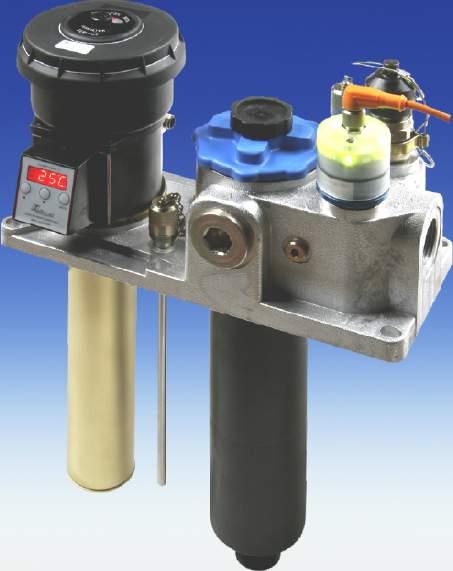
132
133
134
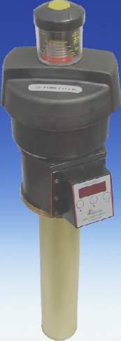
135
136 Level Control NS 61-9 D 9 - VW Specification - Technical Data Ø90 Ø7 M1x1 Operating pressure max. 1 bar Operating temperature max. 80 C Spec. gravity of fluid min. 0.8 kg/dm³ 6xø6 Material: Float SK 610 hard PU Switch tube brass Flange PA 6 L1=min 0 F00050D Clearence min.ø60 Level contacts Function Min. distance of contact Max. voltage Max. current Contact load K10 NO 0 mm V 0.5 A 10 VA L=max.10 L=min.70 Connector socket M1 (with female plug fixed ) Protection class IP 67 LED-female plug not included in delivery Min. 0 SK 610 5,5 ø Wiring diagram 1 L1 L gn rd ye 5 All figures at empty reservoir Order Information Type Part No. L L1 L NS 61-9 D Variable Variable NO* Variable NO* NO = normally open we reserve the right to amend specifications DE /01
137 Fluidcontrolterminal FC-T G1/-75-BMW - BMW specification - Systematic oil care is of great importance to operators of fluid power and lubrication systems who wish to minimize maintenance costs and optimize the durability of both the oil and system components. Checking both cleanliness and chemical composition is made easier by having a dedicated sampling port. Topping off the system through a dedicated G1/ port fitted with a quick release coupling ensures cleanliness and facilitates the use of filter carts. By incorporating the above features with a level control, temperature control and breather filter with condition indicator, BÜHLER has designed an integrated solution giving cost savings on installation. It should be noted that the filler port is totally isolated from the float tube in order to prevent incorrect level readings while filling/topping off. The fluidcontrol terminal FC-T G1/-75-DC 75BMW in the configuration shown complies with BMW requirements. It provides two M1 connector sockets, a temperature display and preset level contacts. Please note that our product line contains many more options. Level controls Temperature controls DIN - flange Filling port G1/ µm breather filter including fill prevention insert Clogging indicator Compact dimensions Easy installation DE /01
138 Technical Data Operating pressure max. 1 bar Operating temperature max. 80 C Density of fluid min. 0.8 kg/dm³ (0.09 lb/in³) Material: Float SK 610 hard PU Switch tube brass Stilling tube brass Flange Breather galvanised steel PA Retention rate SM-L = µm Level contact Min. distance between contacts Max. voltage Max. current Max. contact load K101 and K10 0 mm V 0.5 A 10 VA Thermotronic 71 Range of temperature display from -0 to +10 C / to 8 F Range of alarm indication 0 to +99 C or to 10 F Programmable set points Material housing Display PA, IP65 four digit seven segment-led-display and three light emitting diodes for level status display Current consumption at power up about 10 ma for 100 ms Operating current consumption approx 0-50 ma Supply voltage VDC ±10 % Output PNP Ambient temperature 0-70 C Accuracy 1 % of full range Resolution 1 C / F Programming via three touch keys Temperature sensor PT 100 General description of Thermotronic 71 The Thermotronic 71 is a combined microprocessor controlled digital display and control unit for monitoring and stabilizing the operating temperature in fluid power systems L = 0 L min.60 min.0 L1 Clearance Ø60,5 View A 6 Ø View B Ø View A View B F00061X F00059D 6xØ6 180 Ø7 Ø90 G1/ View C Thermotronic 71 View C Thermotronic 71 THERMOTRONIK 71 Bühler Technologies GmbH MADE IN GERMANY MODE Connector xm1 M1x1 70 The actual temperature is displayed on a high-visibility LED display. The status of the entire unit (output, sensor, broken wire) is indicated by separate LED s. The value can be set to Celsius or Fahrenheit. Programming is by touch keys. The settings are protected against unauthorized operation by key lock. 50% 75% 100% AIRFILTER SERVICE 51 M1x1 F00007X Wiring Diagram Normal position: float on top = filled reservoir 1- + V DC - GND - T1 Warning - T Deactivation rt - L1 Warning - L Deactivation 1- + V DC - GND F0001D B = Temperature out L ge gr A = Level out L1 Order Information FC-Terminal G1/-75BMW Part-no Connector Display L = L1= L= Temperature- Temperaturecontact T1 contact T xm1 yes 50mm 150 NO * 190 NC * 50 C / NC * 60 C / NC * xm1 yes 70mm 150 NO * 00 NC * 50 C / NC * 60 C / NC * xm1 yes 50mm 00 NO * 00 NC * 50 C / NC * 60 C / NC * *NC=normally closed / NO=normally open Accessories Part No Connecting cable M1x1 with 1 x 5 pole M1 plug cable length:,0m we reserve the right to amend specifications
139 Fluidcontrolterminal FC-T G1/-75-DC - Daimler specification - Systematic oil care is of great importance to operators of fluid power and lubrication systems who wish to minimize maintenance costs and optimize the durability of both the oil and system components. Checking both cleanliness and chemical composition is made easier by having a dedicated sampling port. Topping up the system through a dedicated G1/ port fitted with a quick release coupling ensures cleanliness and facilitates the use of filter carts. By incorporating the above features with a level control, temperature control and breather filter with condition indicator, BÜHLER has designed an intergrated solution giving cost savings on installation and tank apertures. It should be noted that the filler port is totally isolated from the float tube in order to prevent incorrect level readings whilst filling/topping up. The fluidcontrolterminal FC-T G1/-75-DC 75DC in this configuration complies with the Daimler requirements. It provides two M1 connector sockets, a temperature display and preset level contacts. Please note that our programme contains more Daimler specific versions of the Nivotemp and Nivovent series. Level controls Temperature controls DIN - flange Filling port G1/ µm breather filter including fill prevention insert Clogging indicator Compact dimensions Easy installation DE /01
140 Technical Data Operating pressure max. 1 bar Operating temperature max. 80 C Spec. gravity of fluid min. 0.8 kg/dm³ Dimensions (mm) View A Ø117 Material Float SK 610 Switch tube Stilling tube Flange Breather Filter element (retention rate) hard PU brass brass galvanised steel PA SM-L ( µm) View C Thermotronic 71 Level contact K101 and K10 Function NC / NO* Min. distance between contacts 0 mm Max. voltage V Max. current 0.5 A Contact load 10 VA * NC = normally closed / NO = normally open, all figures at empty reservoir 56 L1 F00059D 180 G1/ Thermotronic 71 Range of temperature display from -0 to +10 C / to 8 F Range of alarm indication 0 to +99 C or to 178 F Programmable set points Material housing Display PA, IP65 four digit seven segment- LED-display, light emitting diodes for status display Current consumption at power up about 10 ma for 100 ms Operating current consumption approx 0-50 ma Supply voltage VDC ±10 % Output PNP Ambient temperature 0-70 C Accuracy 1 % of full range Resolution 1 C / F Programming button key pad Temperature sensor PT 100 General description of Thermotronic 71 The Thermotronic 71 is a combined microprocessor controlled digital display and control unit for monitoring and stabilizing the operating temperature in fluid power systems. The actual temperature is displayed on a high visibility LED display. The status of the entire unit (output, sensor, broken wire) is indicated by separate LED s. The value can be set to Celsius or Fahrenheit. Programming is by touch keys. The settings are protected against unauthorized operation by key lock. L = L Min.60 Min.0 Clearance Ø60,5 6 Ø View B 50% F00061X View A 75% 100% AIRFILTER SERVICE View B 6xØ6 Ø7 Ø90 View C Thermotronic M1x1 THERMOTRONIK 71 Bühler Technologies GmbH MADE IN GERMANY MODE Connector xm1 M1x1 70 F00007X Wiring Diagram Normal position: float on top = filled reservoir 1- + V DC - GND - T1 warning - T deactivation rt - L1 warning - L deactivation 1- + V DC - GND F0001D B = Temperature out L ge gr A = Level out Order Information FC-T G1/-75DC L1 Part-no Connector Display L = L1= L= Temperature- Temperaturecontact T1 contact T xm1 yes 50 mm 150 mm NC * 190 mm NO * 50 C / NC * 60 C / NC * xm1 yes 70 mm 150 mm NC * 00 mm NO * 50 C / NC * 60 C / NC * xm1 yes 70 mm 00 mm NC * 00 mm NO * 50 C / NC * 60 C / NC * xm1 yes 50 mm 00 mm NC * 00 mm NO * 50 C / NC * 60 C / NC * *NC=normally closed / NO=normally open Accessories Part No Connecting cable M1x1 with 1 x 5 pole M1 plug cable length:,0m we reserve the right to amend specifications
141 Fluidcontrolterminal G/ tedrive - tedrive Germany - Specification - Technical Data Max. operating pressure 1 bar Max. operating temperature 80 C Min. density of fluid 0. 8 kg/dm³ Material Float SK 610 hard PU Switch tube brass Stilling tube brass Housing material PA 1 Flange galvanised steel Breather retention rate SM-L ( µm) Plan view 69 Ø View C Level contacts K101 and K10 Function L1 = NO / L = NO* Max. voltage V DC Max. current 0.5 A Max. contact load 10 VA * NO = normally open, NC = normally closed Temperature sensor Thermotronik 71 Range of temperature display from -0 to +10 C / to 8 F Alarm indicator range 0 to +99 C or to 178 F Display four digit seven segment- LED-Display Operating current consumption about 0-50 ma Supply voltage VDC ±10 % Output switches x PNP T1 = 65 C NC T = 75 C NC Ambient temperature 0-70 C Accuracy 1 % of full scale Resolution 1 C / F Programming button key pad Connector x M1 Protection class IP 65 Wiring Diagram All figures at empty reservoir Connector A Connector B F0006X 1 + V DC 1 GND K101 K10 Thermotronik TT-71 Temp. T1 Temp. T Ø90 L+59,5 Ø7 L L L1 Sample tube Tank side Sample tube Suction pipe Thermotronik View B Sample point outlet G1/8 View C Thermotronik 71 57, Min.60 Ø59 Clearance 6xØ6 View B Connectors x M1 1. Contact K101 NO 6. Contact K10 NO,5 Suction pipe = long sample tube G/ Tank side=short sample tube Filling port Walther Typ: LP-019 Plan view 50% 75% 100% AIRFILTER SERVICE 180 Order Information 60 F0006D We reserve the right to amend specification Type Part No. L L1 L T1 T FC-T G/-75 GETRAG mm 0 mm NO 190 mm NO 65 C NC 75 C NC FC-T G/-75 GETRAG mm 0 mm NO 10 mm NO 65 C NC 75 C NC Accessories Part No Connecting cable M1x1 with 1 x 5 pole M1 plug cable length:,0m DE /01
142 Fluidcontrolterminal G1/-75-VST - tedrive Germany - specification - Technical Data Ø10 Max. operating pressure 1 bar Max. operating temperature 80 C Min. density of fluid 0.8 kg/dm³ Material Float SK 610 hard PU Switch tube brass Stilling tube brass Flange galvanised steel Breather PA Breather type Hydac BF P 7 F UBM Temperatur 8 View C ca.18 Level contact K101 and K10 Function NC / NO* Min. distance between contacts 0 mm Max. voltage V Max. current 0.5 A Max. contact load 10 VA * NC = normally closed / NO = normally open, all figures at empty reservoir 56 L1 180 Thermotronic 71 Range of temperature display from -0 to +10 C / to 8 F Alarm indicator range 0 to +99 C or to 178 F Programmable set points Material housing Display PA, IP65 four digit seven segment- LED-display, light emitting diodes for status display Current consumption at power up about 10 ma for 100 ms Operating current consumption approx 0-50 ma Supply voltage VDC ±10 % Output PNP Ambient temperature 0-70 C Accuracy 1 % of full range Resolution 1 C / F Programming button key pad Temperature sensor PT 100 L Ø 90 min. 60 L Ø 7 Clearance,5 6 Ø 59 Ø 0 View B View B 6xØ6 View C Thermotronik 71 THERMOTRONIK 71 Bühler Technologies GmbH MADE IN GERMANY Filling port Stäubli G1/ (NW11) MODE Wiring Diagram Normal position: float on top = filled reservoir 1- + V DC - GND - T1 warning - T deactivation rt - L1 warning - L deactivation 1- + V DC - GND F0001D B = Temperature out L ge gr A = Level out Order Information FC-T G1/-75 VST L1 We reserve the right to amend specification Part-no Connector Display L = L1= L= T1 T xm1 yes 50mm 10mm NC * 160mm NO * 50 C / NC * 55 C / NC NC=normally closed / NO=normally open Accessories Part No Connecting cable M1x1 with 1 x 5 pole M1 plug cable length:,0m DE /01
143 Fluidcontrolterminal GM-GL - Opel / GM Specification - Technical Data Max. operating pressure 1 bar Max. operating temperature 80 C Min. density of fluid 0.8 kg/dm³ Material Float SK 610 hard PU Switch tube brass Stilling tube brass Housing material PA 1 Flange galvanised steel Breather retention rate SM-L ( µm) Perbunan gasket (x) ø117 F00096X Drains on circumference Male plug Protection class M1 (-pol.) IP 67 with female plug fixed Cork gasket L1=10 Level contacts Function Max. voltage Max. current Max. contact load x K10 NO V AC/DC 0.5 A 10 VA L=0 Scope of delivery Sample point outlet hose coupling Rico-Mini DN 5 Breather filter PI 015-S:M-L Head screws 6 x M5x80 Gaskets GI-cork-gasket x Perbunan gasket 50 ø ø5 L=7 6 Wiring diagram Normal position = at filled reservoir Clearance ø60 1 +VDC ø90 ø7 L1 Warning L Deactivation F00095X 6 x ø6 F00096X Order Information Type Part No. L L1 L Fluidcontrolterminal GM-GL mm 10 mm NO* 0mm NO* NO=normally open we reserved the right to amend specification Accessories Part No Connecting cable M1x1 with 1 x 5 pole M1 plug cable length:,0 m DE /01
144 Fluidcontrolterminal GM-D - Opel / GM Specification - Technical Data Operating pressure 1 bar Operating temperature max. 80 C Lowest specific gravitymin. 0.8 kg/dm³ Material Float SK 610 hard PU Switch tube brass Stilling tube brass Housing material PA 1 Flange galvanised steel Breather retention rate SM-L ( µm) Male plug Protection class Level contacts Function Max. voltage. Max. current Max. contact load M1 (-pol.) IP 67 with female plug fixed x K10 L1 = NC / L = NO 0 V AC/DC 0.5 A 10 VA Perbunan gasket(x) Cork gasket ø117 ø F0009X 5 L1=10 L=0 Drains on circumference L=7 Scope of delivery Sample point outlet Minimess 160 Breather filter PI 015-SM-L Visual filter indicater TB 76/1 Head screws 6 x M5x80 Gaskets GI-cork-gasket x Perbunan gasket 50 ø5 Clearance ø60 6 Wiring Diagram Normal position = at filled reservoir 1 +VDC L1 warning ø90 ø7 L deactivation F0009X F0009X 6 x ø6 Order Information Type Part No. L L1 L Fluidcontrolterminal GM-D mm 10mm NC 0mm NO *NC=normally closed / NO=normally open we reserved the right to amend specification Accessories Part No Connecting cable M1x1 with 1 x 5 pole M1 plug cable length:,0 m DE /01
145 Nivotemp 6-ej-LED-M1 - Daimler specification - By researching existing standards for fluid power packs including DIN 6 regarding liquid level control, it was found that measuring to 00 mm depth was sufficient to control the level. Therefore the Bühler standard length of 70mm is sufficient and covers most applications. Flange mounting is almost universal for breather/filler units so it is also suitable for mounting level controls. The Nivotemp 6-ej-LED-M1 in this configuration complies with the Daimler requirements. The LED s into the transparent socket with an M1 connector indicate the working condition for the level. Adjustable level contacts Bistable level contacts = only one float High float sensitivity International standard flange dimensions Easy installation Please note that our product range contains more Daimler specific versions of the Nivotemp and Nivovent series. DE /01
146 Technical data Dimensions (mm) Operating pressure max. 1 bar Operating temperature max. 80 C Spec. gravity of float min. 0.8 kg/dm³ Material: Float SK 610 hard PU Switch tube brass Flange PA 6 6 Connector M1x1 transparent LED-socket Level contacts Function NC / NO* Min. distance of contact 0 mm Max. voltage V Max. current 0.5 A Max. contact load 10 VA * NC = normally closed / NO = normally open All figures at empty reservoir L L1 F0008D Male plug M1 x 1 ( pol. ) Protection class IP67 with female plug fixed Clearance ø60 Wiring Diagramm Normal position = at filled reservoir,5 L min. 0 SK L L F0009D 6xø6 Ordering Information Type Part No. L1 L Length L Nivotemp 6-ej-LED-M mm NC * 00 mm NO * 70 mm Nivotemp 6-ej-LED-M mm NC * 00 mm NO * 50 mm * NC = normally closed / NO = normally open Accessories Part No Connecting cable M1x1 with 1 x 5 pole M1 plug cable length:,0 m we reserve the right to amend specifications
147 Nivotemp 61-1-TKÖ-..RD-M1 - Renault Specification - Technical Data Ø 90 Ø 7 Operating pressure max. 1 bar Operating temperature max. 80 C Spec. gravity of float min. 0.8 kg/dm³ M1 6 x Ø6 Material Float SK 610 Switch tube Flange Stilling tube hard PU brass PA brass Level contacts Function Min. distance of contact Max. voltage Max. current Max. contact load K10 NO 0 mm V 1.0 A 10 VA F00050X Clearance min.ø60 Temperature contacts Max. voltage Max. current Contact load Hysteresis Switch point V.5 A 100 VA 10 K ± K TKÖ-60 = 60 C NC TKÖ-70 = 70 C NC L1 (NO) Connector Protection class male plug M1 ( pol.) female plug not in scope of delivery IP67 ( with female plug fixed) L=70 Wiring diagram All figures at empty reservoir 1 Level contact (NO) 6 SK 610 F00050X Temperature contact (NC),5 Ø Ø 51 Order Information Type Part No. L L1 Temperature 61-1-TKÖ-70RD-M1-V mm 00 mm NO * 70 C NC * 61-1-TKÖ-70RD-M1-V mm 00 mm NO * 70 C NC * 61-1-TKÖ-60RD-M1-V mm 00 mm NO * 60 C NC * * NO = normally open, NC = normally closed Accessories Part No Connecting cable M1x1 with 1 x 5 pole M1 plug cable length:.0 m we reserve the right to amend specifications DE /01
148 Nivotemp 61-1-TKÖ-..RD-M1-VA - Renault specification - Technical Data Ø90 Ø7 Operating pressure max. 1 bar Operating temperature max. 80 C Spec. gravity of float min. 0.8 kg/dm³ Material Float SK Switch tube Flange PA Stilling tube Level contacts Function Min. distance of contact Max. Voltage Max. current Contact load Temperature contacts Max. voltage Max. current Contact load Hysteresis Switch point K10 NO 0 mm V 1.0 A 10 VA V.5 A 100 VA 10K ± K TKÖ-70 = 70 C NC Connector male plug M1 x1(pol. ) female plug not in scope of delivery Protection class IP67 (with female plug fixed) L=70 L1 (NO) 7 F00050X M1 6xØ6 Clearance min.ø61 Wiring diagram All figures at empty reservoir 55 1 Level contact (NO) SK 1 Temperature contact (NC) Ø51 F00050X Ø 60, Order Information Type Part No. L L1 Temperature 61-1-TKÖ-70RD-M1-VA mm 00 mm NO 70 C NC 61-1-TKÖ-70RD-M1-VA mm 00 mm NO 70 C NC Accessories Part No Connecting cable M1x1 with 1 x 5 pole M1 plug cable length:.0 m we reserve the right to amend specifications DE /008
149 Nivotemp 61-1-TKÖ-..RD-M - Renault specification - Technical Data Max. operating pressure 1 bar Max. operating temperature 80 C Min. density of fluid 0.8 kg/dm³ Ø 90 Ø 7 Material Float SK 610 Switch tube Flange Stilling tube hard PU brass PA brass 65 6 x Ø6 Level contacts Function Min. distance of contact Max. Voltage Max. current Max. contact load K10 NO 0 mm 0 V 1.0 A 10 VA F000505X Clearance min.ø 60 Temperature Contacts Max. voltage 0 V Max. current.5 A Contact load 100 VA Hysteresis 10 K ± K Switch point TKÖ-70 = 70 C L1 (NO) Connector Protection class M (-pol. + PE) IP 65 L Wiring diagram All figures at empty reservoir Level contact (NO) 1 6 SK 610 Temperature contact (NC),5 Ø PE F000506X Ø 56 Order Information Type Part No. L L1 Temperature 61-1-TKÖ-70RD-M-V mm 00 mm NO * 70 C NC * 61-1-TKÖ-70RD-M-V mm 00 mm NO * 70 C NC * 61-1-TKÖ-70RDM-V mm 80 mm NO * 60 C NC * 61-1-TKÖ-70RD-M-V mm 10 mm NO * 70 C NC * 61-1-TKÖ-70RD-M-V mm 170 mm NO * 60 C NC * * NO = normally open, NC = normally closed we reserve the right to amend specifications DE /01
150 Nivotemp 61-1-TKÖ-..RD-M-VA - Renault Specification - Technical Data Operating pressure max. 1 bar Operating temperature max. 80 C Spec. gravity of float min. 0.8 kg/dm³ Ø90 Ø7 Material Float SK Switch tube Flange PA Stilling tube xØ6 Level contacts Function Min. distance of contact Max. Voltage Max. current Contact load K10 NO 0 mm 0 V 1.0 A 10 VA F000507X Clearance min.ø61 Temperature contacts Max. voltage Max. current Contact load Hysteresis Switch point Connector Protection class 0 V.5 A 100 VA 10 K±K TKÖ-70 = 70 C NC M (-pol. + PE) IP 65 L=70 L1 (NO) Wiring diagram All figures at empty reservoir Level contact (NO) 55 1 SK 1 Temperature contact (NC) Ø51 Ø 60, PE F000506X Order Information Type Part No. L L1 Temperature 61-1-TKÖ-70RD-M-VA mm 00 mm NO 70 C NC 61-1-TKÖ-70RD-M-VA mm 00 mm NO 70 C NC we reserve the right to amend specifications DE /008
151 Nivotemp 61-1-TKÖ-..RD-M1 - PSA Peugeot Specification - Technical Data Max. operating pressure 1 bar Max. operating temperature 80 C Min. density of fluid 0.8 kg/dm³ Ø 90 Ø 7 M1 6 x Ø6 Material Float SK 610 Switch tube Flange Stilling tube hard PU brass PA brass Level contacts Function Min. distance of contact Max. Voltage Max. current Max. contact load K10 NO 0 mm V 1.0 A 10 VA F00050X Clearance min.ø60 Temperature contacts Max. voltage Max. current Contact load Hysteresis Switch point V.5 A 100 VA 10 K ± K TKÖ-60 = 60 C NC TKÖ-70 = 70 C NC L1 (NO) Connector Protection class male plug M1 ( pol.) female plug not in scope of delivery IP67 ( with female plug fixed) L=70 Wiring diagram All figures at empty reservoir 1 Level contact (NO) 6 SK 610 F00050X Temperature contact (NC),5 Ø Ø 51 Order information Type Part No. L L1 Temperature 61-1-TKÖ-70RD-M1-V mm 00 mm NO * 70 C NC * 61-1-TKÖ-70RD-M1-V mm 00 mm NO * 70 C NC * 61-1-TKÖ-60RD-M1-V mm 00 mm NO * 60 C NC * * NO = normally open, NC = normally closed Accessories Part No Connecting cable M1x1 with 1 x 5 pole M1 plug cable length:.0 m we reserve the right to amend specifications DE /01
152 Nivotemp 61-1-TKÖ-..RD-M1-VA - PSA Peugeot Specification - Technical Data Ø90 Ø7 Operating pressure max. 1 bar Operating temperature max. 80 C Spec. gravity of float min. 0.8 kg/dm³ Material Float SK Switch tube Flange PA Stilling tube Level contacts Function Min. distance of contact Max. Voltage Max. current Contact load Temperature contacts Max. voltage Max. current Contact load Hysteresis Switch point K10 NO 0 mm V 1.0 A 10 VA V.5 A 100 VA 10 K ± K TKÖ-70 = 70 C NC Connector male plug M1 x1(pol. ) female plug not in scope of delivery Protection class IP67 (with female plug fixed) L=70 L1 (NO) 7 F00050X M1 6xØ6 Clearance min.ø61 Wiring diagram All figures at empty reservoir 55 1 Level contact (NO) SK 1 Temperature contact (NC) Ø51 F00050X Ø 60, Order Information Type Part No. L L1 Temperature 61-1-TKÖ-70RD-M1-VA mm 00 mm NO 70 C NC 61-1-TKÖ-70RD-M1-VA mm 00 mm NO 70 C NC Accessories Part No Connecting cable M1x1 with 1 x 5 pole M1 plug cable length:.0 m we reserve the right to amend specifications DE /008
153 Nivotemp 61-1-TKÖ-..RD-M - PSA Peugeot Specification - Technical Data Max. operating pressure 1 bar Max. operating temperature 80 C Min. density of fluid 0.8 kg/dm³ Ø 90 Ø 7 Material Float SK 610 Switch tube Flange Stilling tube hard PU brass PA brass 65 6 x Ø6 Level contacts Function Min. distance of contact Max. Voltage Max. current Max. contact load K10 NO 0 mm 0 V 1.0 A 10 VA F000505X Clearance min.ø 60 Temperature contacts Max. voltage 0 V Max. current.5 A Contact load 100 VA Hysteresis 10 K ± K Switch point TKÖ-70 = 70 C L1 (NO) Connector Protection class M (-pol. + PE) IP 65 L Wiring diagram All figures at empty reservoir 1 Level contact (NO) 6 SK 610 Temperature contact (NC),5 Ø PE F000506X Ø 56 Order Information Type Part No. L L1 Temperature 61-1-TKÖ-70RD-M-V mm 00 mm NO * 70 C NC * 61-1-TKÖ-70RD-M-V mm 00 mm NO * 70 C NC * 61-1-TKÖ-70RD-M-V mm 80 mm NO * 60 C NC * 61-1-TKÖ-70RD-M-V mm 10 mm NO * 70 C NC * 61-1-TKÖ-70RD-M-V mm 170 mm NO * 60 C NC * * NO = normally open, NC = normally closed we reserve the right to amend specifications DE /01
154 Nivotemp 61-1-TKÖ-..RD-M-VA - PSA Peugeot Specification - Technical Data Operating pressure max. 1 bar Operating temperature max. 80 C Spec. gravity of float min. 0.8 kg/dm³ Ø90 Ø7 Material Float SK Switch tube Flange PA Stilling tube xØ6 Level contacts Function Min. distance of contact Max. Voltage Max. current Contact load K10 NO 0 mm 0 V 1.0 A 10 VA F000507X Clearance min.ø61 Temperature contacts Max. voltage Max. current Contact load Hysteresis Switch point Connector Protection class 0 V.5 A 100 VA 10 K ± K TKÖ-70 = 70 C NC M ( -pol. + PE) IP 65 L=70 L1 (NO) Wiring diagram All figures at empty reservoir 55 1 Level contact (NO) SK 1 Temperature contact (NC) Ø51 Ø 60, PE F000506X Order Information Type Part No. L L1 Temperature 61-1-TKÖ-70RD-M-VA mm 00 mm NO 70 C NC 61-1-TKÖ-70RD-M-VA mm 00 mm NO 70 C NC we reserve the right to amend specifications DE /008
155 Thermotronic 61-AAG Thermotronic 61-AAG - Audi Specification Since the viscosity of oil changes with temperature precise control of the actual temperature is most important in fluid power and lubrication systems. Depending on the application, continuous and precise control is essential. The Thermotronic 61 series offers modern solid state electronics with an LED display for excellent visibility. This product was developed for applications in the fluid power industry. The unit is based on a microprocessor and features up to six individually programmable alarm outputs, can be set in C or F and has a maximum and minimum memory. The Thermotronik allows almost all important control functions in hydraulic and lube systems such as minimum temperature, heater on/off, cooler on/off, alert, emergency off. Operation and settings are done via three keys on the front panel. The unit can be installed as a remote display or directly attached to the sensor on the tank top. Freely programmable set points Digital LED display Maximum / minimum memory Data storage in case of power supply failure Display in C or F Various cable connectors Easy installation Versatile combinations The Thermotronic 61 AAG + in the configuration shown overleaf complies with the AUDI requirements. DE /008
156 Technical Data TF M-PT 100 Material probe brass Max. operating pressure 5 bar Length of probe 80 mm Temperature sensor PT 100 class B DIN / IEC 751 / W Connector Male plug M1 ( pol. ) Protection class IP67 Thermotrmotronik 61 Range of temperature display from -0 to +10 C / to 8 F Range of alarm indication 0 to +99 C or to 178 F Programmable set points AAG = x AAG=x Housing ABS-plastic Depth of housing 55 mm Protection class IP 65 Display three digit seven segment-and LED-display light emitting diodes for status display Current consumption at power up about 10 ma for 100 ms Operating current consumption about 0-70 ma Supply voltage VDC ±10 % Output switches max. V / 1A Ambient temperature 0-70 C Accuracy 1 % of full scale Resolution 1 C / F Programming via three touch keys Connector in M1 ( -pol.) Connector out AAG = 1xM1(5-pol.) AAG=xM1(5-pol.) Thermotronik 61-AAG 8 70 A F000D THERMOTRONIK MF MODE MESS-UND REGELTECHNIK GMBH MADE IN GERMANY C Thermotronik 61-AAG 8 70 B 0 A THERMOTRONIK MF MODE MESS-UND REGELTECHNIK GMBH MADE IN GERMANY C TF M-PT 100 G1/ Scope of delivery connection cable x M1 length 1.5 m 80 Wiring diagram Thermotronik 61-AAG TT61 1+VDC -OUT -GND -OUT1 5-PE Source-1 OUT- OUT- PE-5 Thermotronik 61-AAG TT61 1+VDC -OUT -GND -OUT1 5-PE A B A C C 1 Pt100 F000X 1 Pt100 Order Information Thermotronik 61-AAG Thermotronik 61-AAG Part-no. Length L Part-no. Length L mm mm Accessories Part No Connecting cable M1 x 1 with 5 pole M1 plug cable length: m material: PUR
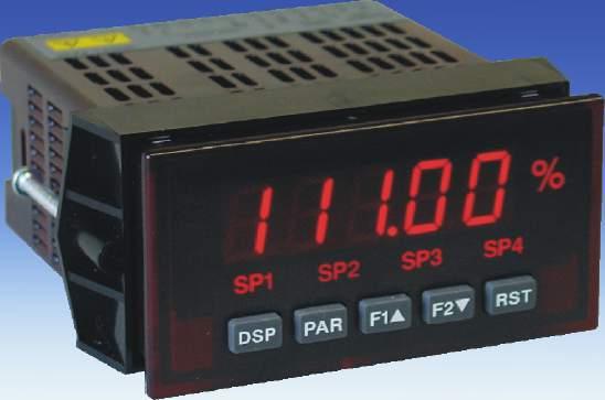
157
158
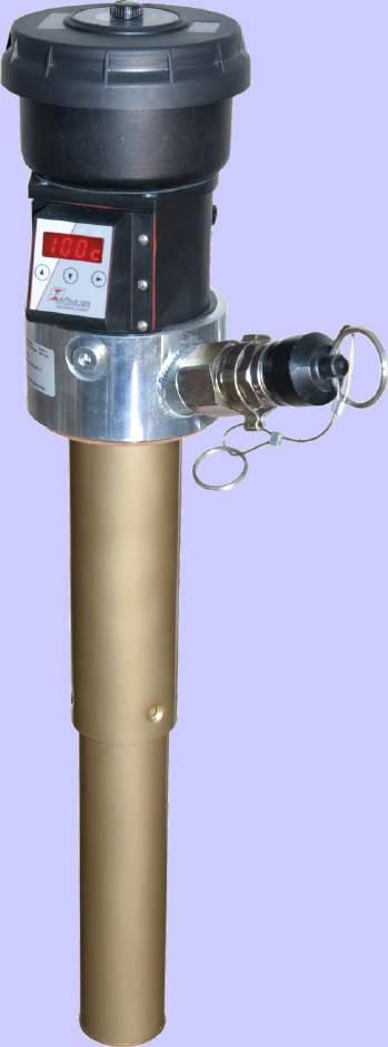
159
160
161

162 Off-line filter unit FGM 0 (60) / Pi This mobile off-line filter unit can be used for in-house applications, as a service unit on installation sites, or for after- sales service applications. Due to its compact and light-weight design, it can be transported easily in service vans. The gerotor pump with either 0 or 60 l/m flow rate emits low noise and contributes to the low weight of the unit. The unit incorporates a drip pan with drain cock and safe storage for suction and pressure hose. The suction hose has a coarse inlet filter to protect the pump from debris. Also a wand is integrated at the outlet. Two fixed and two swivel castor wheels together with a hinged handle provide good maneuverability. The compact and lightweight Mahle Pi 70 filter provides two cartridges with large filtration area at long lifetime, resulting in low maintenance costs. Depending on the application, retention rates between, 6, 10, or 5 can be selected according to the required cleanliness. The Sm-x filter material combines a large spectrum of retention rates with high dirt-holding capacity. DE /01
163 Technical Data Pump Controls Filter Dirt-repellent gerotor pump, directly attached to the shaft of the electric motor. Suction hose with coarse strainer. Motor safeguard, 5 m oil resistant cable CEE plug. Mahle PI 78-57, with optical contamination indicator Bypass Cracking pressure p.5 bar Contamination indicator Cracking pressure p. bar Accessories (included) 0 l/min. 60 l/min. Length Suction hose DN 5 DN m Pressure hose DN 0 DN 0 m Filter cartridge µm, 6µm, 10µm, 5µm (not included) Motor / Pump unit Flow Power Voltage V Rotational speed Max. pressure Max. viscosity l/min. kw rpm bar mm²/s FGM /00 V, 50 Hz ± 5% /80 V, 60 Hz ± 5% FGM /00 V, 50 Hz ± 5% /80 V, 60 Hz ± 5% Dimensions (mm) 810 F00017X Order Information Part-No. Model 70000IE FGM 0 / Pi IE FGM 60 / Pi Filter cartridges (not part of delivery) Part-no. Model Retention rate PX7-1- µm PX µm PX µm PX µm We reserve the right to amend specifications

164 Off-line filter / cooler unit FGSL 15 / FGSL 0 The Reliability and the life time of hydraulic oil and components primarily depend on the cleanliness of the fluid and the limitation of the operating temperature. For systems with varying flow rates off-line filter/cooler units are the most appropriate solution. The unit is based on a Bühler BNK off-line air blast cooler with integrated circulation pump. Its low noise emission and easy maintenance are further advantages. A qualified low pressure filter with broad retention spectrum ensures the required cleanliness class. Due to its compact design, the Bühler FGSL range of off-line units fit well into that segment of applications. Easy integration even allows upgrading of existing systems. DE /01
165 FGSL 15 P Q* S H R E M 67 N J T Q* = Suction side FGSL 0 E P Q* S 67 B G N B øk(x) 100 L O D C A 0 0 F000005D F 0 M H R 100 J T øk(x) L 0 General Data Part No. Model Spec. cooling Cooling Max. flow Power output Noise performance performance rate Poles Weight Volume emission (kw/k) ETD=0K (kw) (l/min) Full load at 00V (kg) (l) db(a)* *DIN EN ISO 7, Class Dimensions (mm) Model O D Accessories: Filter elements and electrical contamination indicators are not included. Please ask for assistance. Q* = Suction side 7001IE FGSL 15/PI008-57/BNK.-15 0,09,6 15 0,75 kw / / 1,9 A, IE FGSL 0/PI008-57/BNK.-0 0,1 5,0 8 0,75 kw / / 1,9 A 5, IE FGSL 0/PI015-57/BNK.-0 0, 9,6 8 0,75 kw / / 1,9 A 0, IE FGSL 0/PI015-57/BNK.-0 0, 1,8 8 0,75 kw / / 1,9 A 5, 7 A B C D E F G H J K L M N O P Q R S T FGSL 15/PI008-57/BNK , xg G1 G1 ¼ FGSL 0/PI008-57/BNK , C A 0 F 0 F000006D xg G1 G1 ¼ FGSL 0/PI015-57/BNK , xg G1 G1 ¼ FGSL 0/PI015-57/BNK , xg G1 G1 ¼ We reserve the right to amend specification
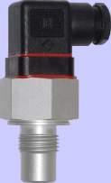
166
167
168
169
170

171
172
173
174
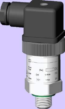
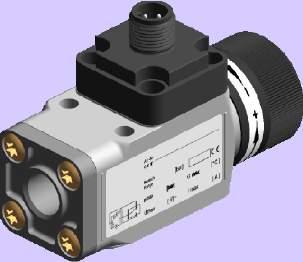
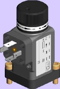
175
176
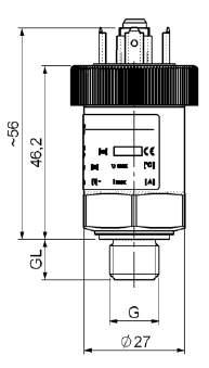
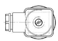
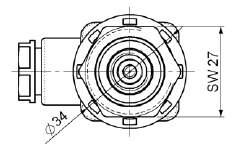
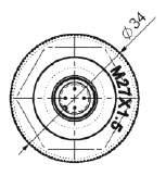
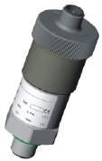
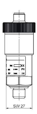
177
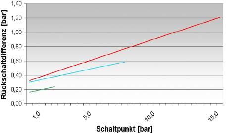
178
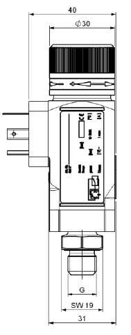
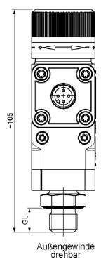
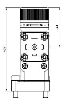
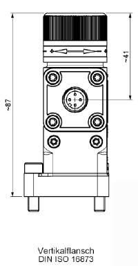
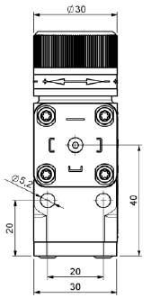
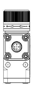
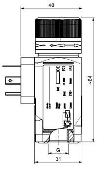
179
180
181 Temperature sensors TF-M-G1/ TF-M/E-G1/ Pt 100 (RTD) temperature probe Continuous temperature acquisition Probe length up to 1 m Housing material brass or stainless steel MK-G1/ MK-G1/ / EK-G1/ Analog output -0 ma Continuous temperature acquisition Most lengths of cable connections between sensor and control unit Probe length up to 1 m Housing material brass or stainless steel Temperature probe Pt 100 with spring TF-M-VAL Temperature probe Pt 100 (RTD) with spring Pt 100 (RTD) temperature probe Continuous temperature acquisition Integrated spring for a variable probe length DE /015 Page 1/
182 Technical data Temperature probe TF with Pt Type TF-M-G1/ TF-E-G1/ design MS VA material probe brass max. operating pressure 5 bar 10 bar connector G1/ G1/ operating temperature -0 C to +100 C lengths 80, 70, 500 (standard) variable up to max mm Temperarture sensor sessor element Pt 100 class, B DIN EN tolerance ±0,8 C sensor wiring, or lead Basic values of the measuring resistors Pt 100 C Ohm 0 100, , , , , ,0 60 1, 70 17, , , ,50 ø11 Connector* M GS M1 (base) pol. + PE (DIN EN ) pol pol. protection class IP 65 IP 65 IP 67** cable connection PG 11 PG 7 *other connectors on request Standard pin assignment 6 1 F0000X 7 PE 59 F00001X 8 6 L= max.1000 SW 6 1 G 1/ mounting depth min F000118D **with casted connector head M1x1 F00000X Eolastic gasket NBR 1 - lead Pt 100 Pt PE 1 - lead Pt 100 Pt lead TF-M TF-E Design MS VA for design MS for design VA Connector M M1 GS only for -lead-wiring Pt 100 Product code for Temperature probe TF G1/ PT100 Example for order You need: Temperature probe brass design, with connector M, length L= 50 mm, PT 100 in -lead circuit, operating pressure bar You order: Temperature probe TF-M-G1/-MS-M-PT100-L / 50 Pt 100 Length (max mm) Variable (please note) Switch form L = - lead L = - lead L = - lead DE /015 Page / we reserve the right to amend specifications
183 Technical data MK/ EK with temperature transmitter 7 Type MK-G1/ EK-G1/ design MS VA material probe brass max. operating pressure 5 bar 10 bar connector G1/ G1/ operating temperature -0 C to +100 C lengths 80, 70, 500 (standard) variable up to max mm Temperature transmitter operating voltage (U B) 10-0 V DC measuring range* 0 C to +100 C tolerance ± 0,8 C ± 1%FS** Analogue output output - 0 ma load Ω max. ( UB - 7,5 V) / 0,0 A tolerance ± 1%FS*** Sensor element sensor element Pt 100 class B DIN EN output Pt 100 ± 0,8 C 6 L= max.1000 SW 6 1 G 1/ immersion depth min. 50 F000118D Eolastic gasket NBR * other measuring ranges and outputs on request ** Consisting of sensor element and analog output *** measuring range (Max - Min) ø11 Example for actual medium temperature 50 C: Deviation Pt100 ±0,8 C which means tolerance 9, C - 50,8 C; Deviation analog output ± 1%FS which means ± 1K; Total tolerance: 8, C - 51,8 C Connector* M M1 (base) pol. + PE (DIN EN ) pol. max. voltage 0 V DC 0 V DC protection class IP 65 IP 67** cable connection PG 11 *other connectors on request 7 **with casted connector head M1x Standard pin assignment F0000X Pt 100 F00000X Pt 100 +V DC 1 out -0mA ma +V DC 1 ma out -0mA PE Type MK Ek Design MS VA for design MS for design VA Product code for temperature transmitter MK / EK G1/ Length (max. 1000mm) Variable (please quote) Connector M M1 Example for order You need: Temperature transmitter brass design, with connector M, output C = -0 ma length L= 50 mm, operating pressure bar You order: Temperature transmitter MK-G1/-MS-M / 50 DE /015 Page / we reserve the right to amend specifications
184 Technical data Temperature probe Pt 100 with spring TF-M-VAL-G1/ Design with external spring Design with internal spring length 8-60 mm material probe aluminium anodized / spring steel gasket NBR max. operating pressure 1 bar fitting G1/ fastening torque 5 Nm operating temperature -0 C to +100 C 6 lengths L spring deflection mm 0 5- mm material probe brass gasket NBR max. operating pressure 1 bar fitting G1/ operating temperature -0 C to +100 C 6 68 wrench size 6 Eolastic gasket NBR 68 wrench size 6 Eolasticgasket NBR with external spring 8 hasta 60 1 G1/ with internal spring L 1 G 1/ ø0 Temperature sensor sensor element Pt 100 class B, DIN EN tolerance ± 0,8 C switching form - lead basic values see chart on page Connector* M pol. + PE ( DIN EN ) protection class IP 65 cable connector PG 11 *on request other connectors Standard pin assignment 1 PE Pt 100 Order information Temperature probe TF-M-VAL with Pt 100 and spring Part No. Length Type mm TF-M-PT100-VAL-M/ mm TF-M-PT100-VAL-M/ mm TF-M-PT100-VAL-M/0 Example for order: You need: Temperature probe with Pt 100 with spring, length 8-60 mm You order: Part No temperature probe TF-M-PT100-VAL-M/60 DE /015 Page / We reserve the right to amend specifications.

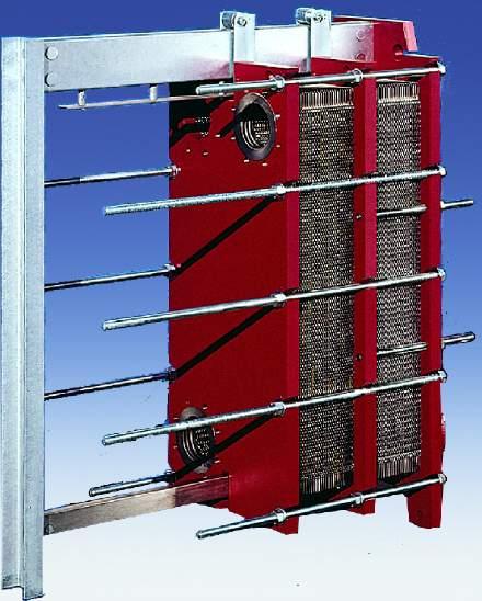
185
186
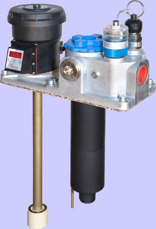
187
188
189
190
191
192
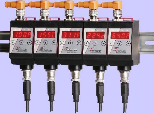
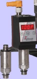
193
194
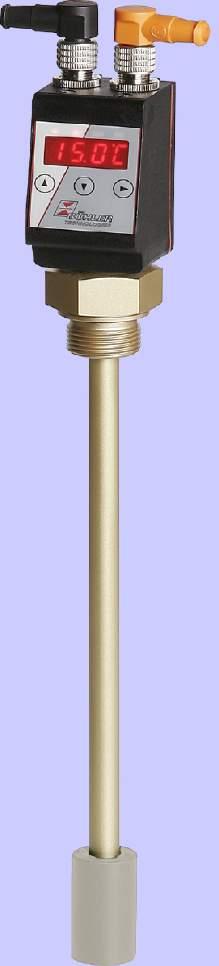
195
196
197
198
199 Level switch NS-OM NS-OM-61/6 NS-OM-61/6 Visual and electrical liquid level monitoring Max. voltage 0 V Variable lengths Version NS-OM-6 with analog output -0 ma for continuous liquid level control NS-OM-6-EasyJust NS-OM-6 Visual and electrical liquid level monitoring Easy Just System: user-optimized adjustability of cordless level contacts Fixed length 80, 70, 500 mm NS-OM-VA NS-OM-VA Visual and electrical liquid level monitoring Max. supply voltage 0 V Stainless steel option for harsh environment Level contact mounted and adjustable outside DE /01 Page 1/
200 Technical data NS OM-61, 6, 6 Basic unit max. operating pressure 1 bar operating temperature -0 C to +80 C min. spec. gravity 0.80 kg/dm³ Material float guide bar switching tube flange (DIN 557) stilling tube (option) hard PU aluminium brass PA brass Type 61 lengths L = 80, 70, 500 (standard) variable up to max 1000 Level contacts K10 W11 function NO / NC* change over max. voltage 0 V 8 V max. current 0.5 A 0.5 A max. contact load 10 VA 0 VA min. distance of contact 0 mm 0mm *NO = normally open / NC = normally closed, all figures at empty reservoir 65 =L L=min. 90 (170) 1 min. 70 (50) L1=min.50 (0) 50 min. 0 F00056D ø60 highest indication point first contact (or 0 ma) last contact (or ma) lowest indication point xø6 NBR gasket Installation dimension=ø60 pitch circle=ø7 Type 6 lengths L = 80, 70, 500 Level contacts function K =NO / NC* or W = change over max. voltage 0 V max. current 0.5 A max. contact load 10 VA min. distance of contact 0 mm *NO = normally open / NC = normally closed, all figures at empty reservoir L=see technical datas 80 ø90 in brackets written values apply to the continuous level output -0 ma Type 6 (continuous level) lengths L = 80, 70, 500, 670, 80 and 970* measuring resistor reed-contact resolution 5 mm operating voltage (U B ) 10-0 V DC output - 0 ma load max. = U B -7. 5V/(00A). *other lengths on request ø9 The Easy System 10 (adjustable) contact board with cm scale Option SSR - stilling tube Included in the delivery mounting bolts M5 (6 pieces) and GI cork-gasket changing of contact function NO/NC by turning the contacts about 180 wireless (bi-stable) level contacts function: NO or NC Connector M (DIN EN ) S6 (DIN EN ) M1 ( base ) x M1 ( base ) pol. + PE 6 pol. + PE pol. x pol. max. voltage 0 V AC/DC* 0 V AC/DC* 0 V DC 0 V DC protection class IP 65 IP 65 IP 67** IP 67**IP 65 cable connection PG 11 M0 x 1,5 (only NS OM-61) 7 7 M1x1 M1x1 M1x A B F00006X F00007X F00008X F0006X level contact(s) NO/NC L1 1 L PE L1 1 L L L 5 6 PE L1 1 L L1 1 A L L 1 B L level contact(s) Wechsler 1 L1 PE 1 L1 L 5 6 PE 1 L1 1 L1 A 1 L B NS OM-6-KN (continuous level) 1 +V DC -0 ma level 1-0 level ma +V DC PE DE /01 Page / * max. 8 V for change over contact / max. 0 V for NS-OM 6 / **with casted connector head / other connectors on request
201 Series NS OM- Product code for NS OM-61, 6 NS OM- Typ 61 6 Easy Just Connector M S6 M1 x M1 (type 61 only) Length (mm) variable (max mm only for type 61) # level contacts 1- Level contact K =NO/NC W = change over Option SSR stilling tube Series NS OM- Product code for NS OM-6 NS OM- Typ 6 (continuous level) Resolution 5mm Connector M M1 Length Option SSR stilling tube Example for order You need: Visual and electrical monitoring of level length 600 mm with contacts K10, 1st contact 100 mm NC, nd contact 0 mm NOr You order: NS OM 61-S6-/ K L1=100 NC, L = 0 NO DE /01 Page /
202 Ø90 Ø7 Technical data mounted left 1 PE mounted right -0 ma NS OM-VA Basic unit max. operating pressure 1 bar operating temperature -0 C to +80 C min. density of fluid 0.80 kg/dm³ Material float SK 90 PU/Al/PP immersion tube flange stilling tube (included in delivery) sight glass PC Type MKS lengths mm 80, 70, 500 variable up to max 80 Contacts type function MKS-1/K NC/ NO* MKS-1/W change over max. voltage 0 V AC/DC 0 V AC/DC max. current 1 A 1 A max. contact load 50 VA 0 VA connector pol. + PE pol. + PE M (DIN EN ) M (DIN EN ) protection class IP65 IP65 part no other contacts on request *NO = normally open / NC = normally closed, all figures at empty reservoir MKS-1/K MKS-1/W 1 PE mounted left 1 PE contact position at empty reservoir Type K (continuous level measurement) lengths mm 80, 70, 500, 670, 80* inch 11, 1.6, 19.7, 6.,.* measuring resistor reed-contact resolution 5 or 10 mm (0. or 0.") operating voltage (U B ) 10-0 V DC output - 0 ma load max. =(UB V) / 0.0 A *other lengths on request 1+VDC Level out mounted right 1 PE L1 = max. 80 L=L1 55 minimum distance highest switch-point minimum distance lowest switch-point lowest switch-point= immersion depth of float x mounting holes ø6 continuous level dispenser (-K) 5 85 MKS - contact GI cork gasket 6 F000096D ø9 ø highest indication point clearance 5 stilling tube Product code for NS OM-VA Type Length (max. 80 mm) Variable (please specify) NS OM-VA-MKS Type 5 10 continuous resolution 5 mm continuous resolution 10 mm Length (mm) NS OM-VA-K Example for order You need: Visual and electrical level monitoring in stainless steel design (VA), length L= 600 mm and x contact MKS 1/W You order: NS OM-VA-MKS / x contact MKS-1W (Part No: ) DE /01 Page / We reserve the right to amend specifications
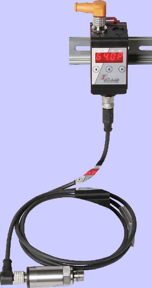
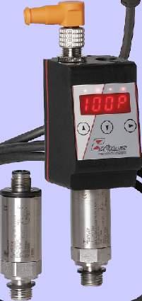
203
204
205
206
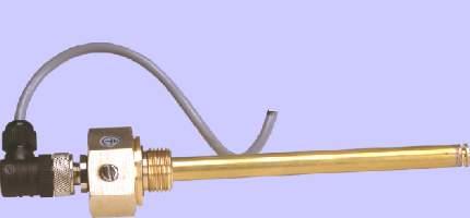
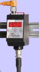
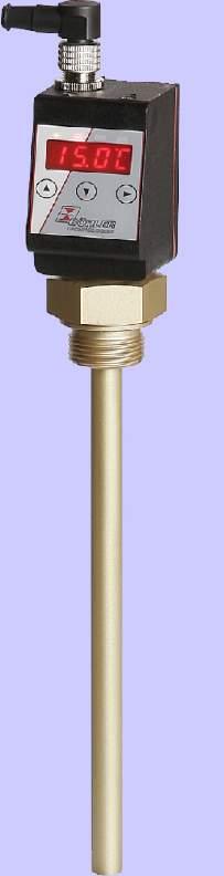
207
208
209
210
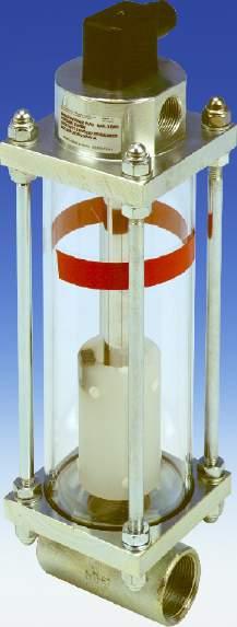
211
212
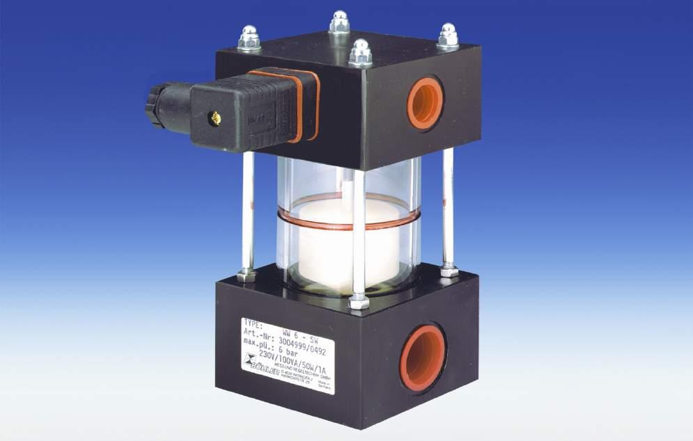
213
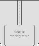
214
VarioDrive C, technical information. VarioDrive C, size 084. VarioDrive C, size 112. VarioDrive C, size 150
 Antriebstechnik_211_5_27_Finale_EN_:Vorlage 27.5.211 1:12 Seite 55 VarioDrive C 56 58 VarioDrive C, size 112 62 VarioDrive C, size 15 67 VarioDrive C VarioDrive C, technical information По вопросам продаж
Двойной электромагнитный клапан DMV/12, DMV-D/12, DMV-DLE/12 DUNGS
 По вопросам продаж и поддержки обращайтесь: Архангельск (8182)63 90 72 Астана (7172)727 132 Белгород (4722)40 23 64 Брянск (4832)59 03 52 Владивосток (423)249 28 31 Волгоград (844)278 03 48 Вологда (8172)26
Servotronic Digital 615 Series
 Servotronic Digital 615 Series Proportional Technology Архангельск (818)6-90-7 Астана (717)77-1 Астрахань (851)99-46-04 Барнаул (85)7-04-60 Белгород (47)40--64 Брянск (48)59-0-5 Владивосток (4)49-8-1 Волгоград
Электромагнитные клапаны для пара Burkert
 По вопросам продаж и поддержки обращайтесь: Архангельск (8182)63 90 72 Астана (7172)727 132 Белгород (4722)40 23 64 Брянск (4832)59 03 52 Владивосток (423)249 28 31 Волгоград (844)278 03 48 Вологда (8172)26
501 series. Aluminium, E-coating treatment
 501 series FEATURES High flow rate up to 400 l/min Wide electrical connection selection : G3 or 580 Fieldbus Electronics, 25 or 37 Pin Sub-D connector, 19 Pin Round connector, 26 Pin Round connector or
TOPAS PMW-basic Hot water meter
 TOPAS PMW-basic Hot water meter Swiss Made Applications The TOPAS PMW-basic product line covers a wide range of applications in hot water measurement. This innovative system offers all types of water measurement
SHORT STROKE CYLINDERS Ø 8 to 100 mm - single and double acting with single/double rod, antirotation device
 SHOT STOKE CYINES 8 to 100 mm - single and double acting with single/double rod, antirotation device Series 441 GENEA etection luid Operating pressure Ambient temperature CONSTUCTION ody Piston rod od
Описание на системы датчиков воздушного зазора. Модель 4000
 По вопросам продаж и поддержки обращайтесь: btn@nt-rt.ru www.bently.nt-rt.ru Архангельск (8182)63-9-72, Астана+7(7172)727-132, Белгород(4722)4-23-64, Брянск(4832)59-3-52, Владивосток(423)249-28-31, Волгоград(844)278-3-48,
503 series. Level C to +50 C spool & sleeve metal-to-metal sealing. Aluminium, E-coating treatment
 FEATURES rate up to 00 l/min Spool & Sleeve or rubber packed technology in the same dimension body Wide electrical connection selection : G3 or 580 Fieldbus Electronics, 25 or 37 Pin Sub-D connector, 19
Пневмоострова Burkert
 По вопросам продаж и поддержки обращайтесь: Архангельск (8182)63 90 72 Астана (7172)727 132 Белгород (4722)40 23 64 Брянск (4832)59 03 52 Владивосток (423)249 28 31 Волгоград (844)278 03 48 Вологда (8172)26
Valve Manifolds. Series сайт: эл. почта:
 Valve Manifolds Series 0 Архангельск (88)6-90-7 Астана (77)77- Астрахань (8)99-6-0 Барнаул (8)7-0-60 Белгород (7)0--6 Брянск (8)9-0- Владивосток ()9-8- Волгоград (8)78-0-8 Вологда (87)6--9 Воронеж (7)0--7
PST-100. Instruction Manual English Version. Please read carefully before use
 PST-100 Instruction Manual English Version Please read carefully before use http://leister.nt-rt.ru По вопросам продаж и поддержки обращайтесь: Архангельск (8182)63-90-72 Астана +7(7172)727-132 Белгород
сайт: почта:
 Архангельск (8182)63-90-72 Астана +7(7172)727-132 Белгород (4722)40-23-64 Брянск (4832)59-03-52 Владивосток (423)249-28-31 Волгоград (844)278-03-48 Вологда (8172)26-41-59 Воронеж (473)204-51-73 Екатеринбург
Kolmeks. Инструкция по эксплуатации (eng)
") Kolmeks Инструкция по эксплуатации (eng) Насосы с преобразованием частоты SC По вопросам продаж и поддержки обращайтесь: Архангельск (8182)63-90-72 Астана +7(7172)727-132 Белгород (4722)40-23-64 Брянск
Kolmeks Инструкция по эксплуатации (eng) Насосы с преобразованием частоты SC По вопросам продаж и поддержки обращайтесь: Архангельск (8182)63-90-72 Астана +7(7172)727-132 Белгород (4722)40-23-64 Брянск
Pressure transmitterses. По вопросам продаж и поддержки обращайтесь: Единый адрес для всех регионов:
 По вопросам продаж и поддержки обращайтесь: Архангельск (8182)63-90-72 Астана +7(7172)727-132 Белгород (4722)40-23-64 Брянск (4832)59-03-52 Владивосток (423)249-28-31 Волгоград (844)278-03-48 Вологда (8172)26-41-59
Электромагнитные клапаны для агрессивных и чистых сред Burkert
 По вопросам продаж и поддержки обращайтесь: Архангельск (8182)63 90 72 Астана (7172)727 132 Белгород (4722)40 23 64 Брянск (4832)59 03 52 Владивосток (423)249 28 31 Волгоград (844)278 03 48 Вологда (8172)26
2012 Series Solenoid Pilot Actuated Valves
 Series Solenoid Pilot Actuated Valves Архангельск (882)63-90-72 Астана (772)727-32 Астрахань (852)99-46-04 Барнаул (3852)73-04-60 Белгород (4722)40-23-64 Брянск (4832)59-03-52 Владивосток (423)249-28-3
Модульные клапаны Burkert
 По вопросам продаж и поддержки обращайтесь: Архангельск (818)63 90 7 Астана (717)77 13 Белгород (47)40 3 64 Брянск (483)59 03 5 Владивосток (43)49 8 31 Волгоград (844)78 03 48 Вологда (817)6 41 59 Воронеж
Каталог продукции DUNGS
 По вопросам продаж и поддержки обращайтесь: Архангельск (818)63 90 7 Астана (717)77 13 Белгород (47)40 3 64 Брянск (483)59 03 5 Владивосток (43)49 8 31 Волгоград (844)78 03 48 Вологда (817)6 41 59 Воронеж
Регулирующие клапаны с электроприводом Burkert
 По вопросам продаж и поддержки обращайтесь: Архангельск (8182)63 90 72 Астана (7172)727 132 Белгород (4722)40 23 64 Брянск (4832)59 03 52 Владивосток (423)249 28 31 Волгоград (844)278 03 48 Вологда (8172)26
FESTO. Документация. Линейные приводы DGC-K (eng) По вопросам продаж и поддержки обращайтесь:
 По вопросам продаж и поддержки обращайтесь:") FESTO Документация Линейные приводы DGC-K (eng) По вопросам продаж и поддержки обращайтесь: Архангельск (8182)63-9-72 Астана +7(7172)727-132 Белгород (4722)4-23-64 Брянск (4832)59-3-52 Владивосток (423)249-28-31
FESTO Документация Линейные приводы DGC-K (eng) По вопросам продаж и поддержки обращайтесь: Архангельск (8182)63-9-72 Астана +7(7172)727-132 Белгород (4722)4-23-64 Брянск (4832)59-3-52 Владивосток (423)249-28-31
DL1000 Electrode Mountings
 DL1 Electrode Mountings (Durafet II ph Electrodes & Mountings for DL421 with and without Vario Pin Durafet Connectors) Pipeline Electrode Mounting (7758 Type) ph ORP Insertion Removal (7774 Type) Sanitary
Kolmeks. Инструкция по эксплуатации (eng)
") Kolmeks Инструкция по эксплуатации (eng) Насосы с преобразованием частоты NC По вопросам продаж и поддержки обращайтесь: Архангельск (8182)63-90-72 Астана +7(7172)727-132 Белгород (4722)40-23-64 Брянск
Kolmeks Инструкция по эксплуатации (eng) Насосы с преобразованием частоты NC По вопросам продаж и поддержки обращайтесь: Архангельск (8182)63-90-72 Астана +7(7172)727-132 Белгород (4722)40-23-64 Брянск
MT4-024/MT4-230 MT8-024/MT8-230
 Smart-T MT4-024/MT4-230 MT8-024/MT8-230 SMLL LINER THERMOELECTRIC CTUTORS PRODUCT DT FETURES No mounting tools required (easily mounted using valve adapter) Water-protected housing design in all mounting
FESTO Документация Поворотные приводы DRRD
 FESTO Документация Поворотные приводы DRRD По вопросам продаж и поддержки обращайтесь: Архангельск (8182)63-90-72 Астана +7(7172)727-132 Белгород (4722)40-23-64 Брянск (4832)59-03-52 Владивосток (423)249-28-31
VersaFlow Mag 3000 Electromagnetic Flow Sensor Technical Datasheet. Specification
 VersaFlow Mag 3000 Electromagnetic Flow Sensor Technical Datasheet Sanitary and hygienic solution The VersaFlow Mag 3000 is the electromagnetic flow sensor for the food and beverage industry. The 3000
Sartolab P The new way for reliable sterile filtration of cell culture media
 Sartolab P The new way for reliable sterile filtration of cell culture media По вопросам продаж и поддержки обращайтесь: Астана+7(7172)727-132, Волгоград(844)278-03-48, Воронеж(473)204-51-73, Екатеринбург(343)384-55-89,
сайт: эл. почта:
 Архангельск (8182)63-90-72 Астана (7172)727-132 Астрахань (8512)99-46-04 Барнаул (3852)73-04-60 Белгород (4722)40-23-64 Брянск (4832)59-03-52 Владивосток (423)249-28-31 Волгоград (844)278-03-48 Вологда
По вопросам продаж и поддержки обращайтесь:
 FESTO Документация Датчики положения SMT/SME-8 По вопросам продаж и поддержки обращайтесь: Архангельск (8182)6-90-72 Астана +7(7172)727-12 Белгород (4722)40-2-64 Брянск (482)59-0-52 Владивосток (42)249-28-1
TEMPERATURE CONTROL AND MONITORING HYDRAULIC COMPONENTS
 Electronic level and temperature control Gasket (NBR) Operating pressure: max. 1 bar Operating temperature: -20 C up to +80 C Ambient temperature: -20 C up to +70 C Weight: approx. 400g Sealing fl uid:
AS-I
 Digital Positioner 8049 Compact digital positioner for pneumatic control valves. Positioner can be integrated into valve actuator (no external moving parts for stroke feedback) Wide range of strokes 3-8
Hydraulic Flanges SAE J 518 С & ISO 6164
 Hydraulic Flanges SAE J 518 С & ISO 6164 Архангельск (8182)63-90-72 Астана +7(7172)727-132 Белгород (4722)40-23-64 Брянск (4832)59-03-52 Владивосток (423)249-28-31 Волгоград (844)278-03-48 Вологда (8172)26-41-59
HONDA. Инструкция по эксплуатации (eng.)
") HONDA Инструкция по эксплуатации (eng.) Лодочные моторы BF 30 DK2 SHGU, BF 30 DK2 SRTU По вопросам продаж и поддержки обращайтесь: Архангельск (8182)63-90-72 Астана +7(7172)727-132 Белгород (4722)40-23-64
HONDA Инструкция по эксплуатации (eng.) Лодочные моторы BF 30 DK2 SHGU, BF 30 DK2 SRTU По вопросам продаж и поддержки обращайтесь: Архангельск (8182)63-90-72 Астана +7(7172)727-132 Белгород (4722)40-23-64
Каталог продукции. Гидравлические борты и подъемники. Единый адрес для всех регионов:
 Архангельск (8182)63-90-72 Астана +7(7172)727-132 Белгород (4722)40-23-64 Брянск (4832)59-03-52 Владивосток (423)249-28-31 Волгоград (844)278-03-48 Вологда (8172)26-41-59 Воронеж (473)204-51-73 Екатеринбург
english Technology in the future SL800 Series
 english Technology in the future http://multione.nt-rt.ru/ SL800 Series По вопросам продаж и поддержки обращайтесь: Архангельск (8182)63-90-72 Астана +7(7172)727-132 Белгород (4722)40-23-64 Брянск (4832)59-03-52
TankConditioner TC. TC visual/ electrical 1.5 GENERAL TECHNICAL SPECIFICATIONS. (10 deep) seals. For further information, please see Point 3.
 seals. For further information, please see Point 3.") ankconditioner C with Breather Filter, Float Switch and emperature Monitoring System C electrical C visual/ electrical 1. ECHNICA SPECIFICAIONS 1.1 UNI CONSRUCION he ankconditioner C is a multi-functional
ankconditioner C with Breather Filter, Float Switch and emperature Monitoring System C electrical C visual/ electrical 1. ECHNICA SPECIFICAIONS 1.1 UNI CONSRUCION he ankconditioner C is a multi-functional
Combics Weighing Platforms CAAPP...
 Combics Weighing Platforms CAAPP... Weighing platforms Large selection of combination options for standard components High weight bearing construction with simultaneous display accuracy High IP protection
Temperature switch. Switching output 2 transistors PNP Logger Ring buffer: 3518 data points Sampling time: s, Off (0)
") Temperature switch Swiss based Trafag is a leading international supplier of high quality sensors and monitoring instruments for measurement of pressure and temperature. Applications Machine tools Hydraulic
Temperature switch Swiss based Trafag is a leading international supplier of high quality sensors and monitoring instruments for measurement of pressure and temperature. Applications Machine tools Hydraulic
Electronic Temperature Sensor ETS 300
 Description: The ETS 300 is a compact electronic temperature sensor with digital display. Two different models are available for optimum adaptation to particular applications. The ETS 300 with built-in
FESTO. Документация. Стандартные распределители VSVA с индивидуальным подключением. По вопросам продаж и поддержки обращайтесь:
 FESTO Документация Стандартные распределители VSVA с индивидуальным подключением По вопросам продаж и поддержки обращайтесь: Архангельск (8182)63-90-72 Астана +7(7172)727-132 Белгород (4722)40-23-64 Брянск
Каталог продукции SULZER
 По вопросам продаж и поддержки обращайтесь: Архангельск (8182)63-90-72 Астана (7172)727-132 Астрахань (8512)99-46-04 Барнаул (3852)73-04-60 Белгород (4722)40-23-64 Брянск (4832)59-03-52 Владивосток (423)249-28-31
3/2-Way Valve DN 15 up to DN 40. Technical Information. normal function, normally closed. distributing, mixing function and shut - off function
 3/2-Way Valve 78 DN 1 up to DN 4 Pneumatically operated 3/2-way valve for the control of neutral and slightly aggressive media. (Stainless steel version, Data sheet Type 781) Compact design Unaffected
По вопросам продаж и поддержки обращайтесь:
 По вопросам продаж и поддержки обращайтесь: Архангельск (8182)63-90-72 Астана (7172)727-132 Астрахань (8512)99-46-04 Барнаул (3852)73-04-60 Белгород (4722)40-23-64 Брянск (4832)59-03-52 Владивосток (423)249-28-31
Float switch with switching contacts and temperature contact, with resistance measuring chain / resistance thermometer, with display and control unit
 Float switch with switching contacts and temperature contact, with resistance measuring chain / resistance thermometer, with display and control unit RE 50/05.0 Replaces: 50 /8 Type ABZMS- Component series
Plastic tube variable area flowmeter for liquids and gases
 Plastic tube variable area flowmeter for liquids and gases Low cost, excellent readability and light weight Simple installation (flanged, threaded or socket ends for solvent or fusion welding connections)
Adjustment range. Seal material. Pressure connection
 0520 Order matrix for electronic pressure switches.3 Type Adjustment range Pressure connection Seal material lectrical connection Type lectronic pressure switch 0520 Adjustment range 1) for NO 0 145 psi
Temperature sensors. Fluidcontrol
 Temperature sensors Changes in the viscosity of hydraulic oil and lubricants due to the temperature requires precisely monitoring and stabilising the operating temperature. Carefully monitoring the temperature
Shipbuilding solutions
 Shipbuilding solutions Level Flow Pressure Worldwide solutions Hundreds of thousands of Trimod Besta level switches ensure the safe voyage of vessels on our oceans Since 1967 the Shipbuilding industry
Electronic Pressure Switch EDS 3000
 Description: The EDS 3000 is a compact, electronic pressure switch with integral digital display. The unit can have one or two switching outputs, and there is the option of an additional analogue output
Red/green-LED for switching state indication (dyn.) Yellow LED for dirt accumulation indication
 Yellow LED for dirt accumulation indication") FLB Series FLB-F2-...-HS (High Speed) - High switching frequency (10kHz) - Integrated electronics - High sensitivity (adjustable via 5-step switch) - Pulse length adjustable via 5-step switch - Dynamic
FLB Series FLB-F2-...-HS (High Speed) - High switching frequency (10kHz) - Integrated electronics - High sensitivity (adjustable via 5-step switch) - Pulse length adjustable via 5-step switch - Dynamic
Electronic Pressure Switches
 96 Pressure Switches Electronic Pressure Switches Electronic E.5 switching output Electronic pressure switches, High-Performance series with one switching output Outstanding overpressure protection (up
Flanged Motor Valve compact DN 15 up to DN
 Flanged Motor Valve compact DN 15 up to DN 50 7232 Motor valve for on/off and modulating operation for neutral and aggressive media. Compact design Self adaption Unaffected by lightly contaminated media
Operating Instructions for Pressure Transmitter with Digital Display. Model: PDA
 Operating Instructions for Pressure Transmitter with Digital Display Model: PDA 1. Contents 1. Contents... 2 2. Note... 3 3. Instrument Inspection... 3 4. Operating Principle... 3 5. Regulation Use...
Pressure Switches. Pressure switches, pneumatic. Pressure switches, electronic
 Contents Description Page Pressure switches, pneumatic, with plug 50 Pressure switches, pneumatic, with flat pins 51 Pressure switches, pneumatic 52 55 with internal thread with flange connection Pressure
OPTISWITCH 4000/5000. Vibration level switches for liquids
 OPTISWITCH 4000/5000 Technical Datasheet Vibration level switches for liquids Operates up to 250 C / 480 F and 64 bar / 925 psi Pump dry-run detection High reliability due to permanent fault monitoring
Axial Turbine Flow Sensor Series Turbotron VTH 25 / VTI 25 / VTM 25
 Installation Instruction Axial Turbine Flow Sensor Series Turbotron VTH 25 / VTI 25 / VTM 25 Table of contents Page 1 Function of Turbotron 1 2 Safety instructions 2 3 Important notes and requirements
Electronic Pressure Switches
 96 Pressure Switches Electronic Pressure Switches Electronic E.6 2 switching outputs Electronic pressure switches, High-Performance series with two switching outputs Outstanding overpressure protection
Sentronic PLUS 614 Series
 Sentronic PLUS 64 Series Proportional Technology www.asco.com PRESSURE CONTROL: 64 SERIES SENTRONIC PLUS Sentronic PLUS Sentronic PLUS is a digitally operated pressure regulator valve. This valve accurately
Solid State Electronic Pressure Switch with Integral LED Display Model PSD-10
 Solid State Electronic Pressure Switch with Integral LED Display Model PSD-10 Electronic Pressure Measurement WIKA Datasheet PSD-10 Applications Hydraulics and pneumatics Filter monitoring Pump control
Sentronic D 608 Series and 609 Series
 Sentronic D 608 Series and 609 Series Proportional Technology www.asco.com PRESSURE CONTROL: 608/609 SERIES SENTRONIC D Sentronic D Sentronic D is a digitally operated pressure regulator valve. Sentronic
Electronic Pressure Switches
 96 Pressure Switches Electronic Pressure Switches Electronic Electronic pressure switches, series, Very attractively priced electronic pressure switches, particularly for high volume deployment High overpressure
INSTRUMENTATION & CONTROL
 Irrigation Controller.................... 172 Window Controller.................... 174 Water Meter Controller.................. 176 Digital Level Switch.................... 177 Filtration Controller Set..................
Turbotron // VTH15, VTM15, VTP15, VTI15
 1 Flow Measuring Turbine flow sensors Turbotron // VTH15, VTM15, VTP15, VTI15 VTH15 BEST SELLER VTM15 Your advantages Series VTH15 VTM15 Cost optimized version For medium temperature up to 120 C Type VTH15
LFT RADAR MICROONDE GUIDATE CONTROLLI DI LIVELLO. LFT level sensor the all-round talent with TDR technology. Dimensional drawing.
 LFT RADAR MICROONDE GUIDATE CONTROLLI DI LIVELLO LFT level sensor the all-round talent with TDR technology Latest technology: TDR sensor with coaxial probe for continual level measurements with analog
Hydraulic Components Oil tanks accessories Industrial controllers
 Temperature control, indication and control of cooling and heating circles Excess temperature safety device of units Level control Used in hydraulic, lubrication and tempering units Up to 7 functions in
Directional Seat Valve Series D4S (Denison)
") Characteristics Seat valves series D4S are designed for directional control functions. A large variety of poppets, springs and covers - including shuttle valves, stroke limiters, solenoid valves (VV01)
Characteristics Seat valves series D4S are designed for directional control functions. A large variety of poppets, springs and covers - including shuttle valves, stroke limiters, solenoid valves (VV01)
Motor Valve GS 3 series DN 15 up to DN 200 with safety spring return
 y% 100 75 50 25 0 Motor Valve GS 3 series Version NR2 8035 DN 15 up to DN 200 TÜV-approval according DIN 32730 for the pressure ratings PN40, ANSI150 and ANSI 300 Technical Information Design Flangeless
fluid technology temperature sensors 1600 intelligent temperature sensor membrane keyboard, USB opto interface
 fluid technology temperature sensors 1600 1 dimensions Ø38 x 118mm temperature operating range -40 to +300 C temperature measuring range from -40 to +300 C M12 socket for PT100 resistance thermometer analog
CONTROLLERS & SPECIAL VALVES
 CONTROLLERS & SPECIAL VALVES G75-C 1, 2 & 4 Valve Controllers.... 70 G75-C-1W & 1W+ Window Controller... 72 G75-DP Differential Pressure Switch.....................................................................
Electromagnetic flowmeters Series FLOMAT Insertion electromagnetic flowmeter for conductive liquids
 Electromagnetic flowmeters Series FLOMAT Insertion electromagnetic flowmeter for conductive liquids For use in large diameter pipes as an economical solution for flow measurement Flow rate measurement
Electrically operated valves Series BM-01, 3/2-way and 2 x 3/2-way G1/8 550 to 660 Nl/min (0.559 to Cv)
") Electrically operated valves Series BM-01, 3/2-way and 2 x 3/2-way G1/8 550 to 660 Nl/min (0.559 to 0.671 Cv) Order code BM-01-310-HNR-462 Series and function BM = Standard Manual override HNT = non-detented
Electrically operated valves Series BM-01, 3/2-way and 2 x 3/2-way G1/8 550 to 660 Nl/min (0.559 to 0.671 Cv) Order code BM-01-310-HNR-462 Series and function BM = Standard Manual override HNT = non-detented
RTD Temperature Sensor omnigrad T -TR 470
 Technical Information TI 272T/02/en 60021665 RTD Temperature Sensor omnigrad T -TR 470 RTD sensor with Pt 100, class A Process connection threaded or with compression fitting Application The Omnigrad T
Miniature Float Switches
 Miniature Float Switches types 200, 201, 203, 204, 207, 209, 274 + low-priced float switches in miniature construction + long life thanks to a non-contact measuring technique with wear-free Reed contacts
Chapter 6: Check Valves
 Contents Chapter : Check Valves Series Description Size Mounting Page Parker Standard DIN / ISO 1/8 1/4 3/8 1/2 3/4 1 0 10 1 25 32 Subplate Screw-in Slip-in SSR RK / RB CS SPZBE SPV / SPZ C4V CPS C4V D4S
English copy version 2010/REV04 PISTON PRESSURE SWITCH DS-117 / DS-112
 English copy version 2010/REV04 PISTON PRESSURE SWITCH DS-117 / DS-112 INTRODUCTION We are known throughout Europe as a leading specialist for piston pressure switches and provide our customers with a
Direct Automation Trade Price List Process Controls Sensors 1
 Direct Automation Trade Price List Process Controls Sensors 1 Sensor & Input Devices Process Controls & Sensors Process/Temperature Controllers & Assessories DPM2-AT-2R-HL ProSense digital panel meter,
Turbine Flow Meters for Liquids
 Turbine Flow Meters for Liquids founded Series Turbotron VT... Turbine Flow Sensors for Liquids DN 15... disturbance insensitive and durable! VT 15 with pulse output The turbine fl ow sensors of the product
Electronic Pressure Switches
 96 Pressure Switches Electronic Pressure Switches Electronic E. Electronic pressure switches, series, Very competitively priced electronic pressure switches High overpressure protection (up to x) Small,
Servotronic Digital 615 Series
 Servotronic Digital 615 Series Proportional Technology www.asco.com PRESSURE CONTROL: 615 SERIES SERVOTRONIC Digital Servotronic Digital Greater versatility in automated production processes: Due to electronics,
Pilot-Operated Directional Control Valves Series D3 - D11
 Catalogue HY11-500/UK Characteristics The D31, D41, D81, D91 and D111 are electrical controlled 4/3 or 4/ way directional control valves. The valves are pilot-operated by an NG6 valve. Pressure and flow
FPT Applications. Features
 FPT 85 Flush Membrane Transmitter Swiss based Trafag is a leading international supplier of high quality sensors and monitoring instruments for measurement of and temperature. The Flush Membrane Transmitter
VP23. 3-way proportional pressure control valve Directly-controlled seat valve with μp-driven pressure control G 1/4 to G 3/4 Nominal diameter 8/16
 VP ll-digital control electronics Variable pressure control, external pressure control upon request Optional: serial interfacing with VP-Tool program Optional actuation via fieldbus (separate data sheet
Compact cylinders series NYD Double acting with magnetic piston, ISO M5 to G1/8 Piston Ø 20 to 100 mm
 Compact cylinders series NYD Double acting with magnetic piston, ISO 21287 M5 to G1/8 Piston Ø 20 to 100 mm 200, 210 220 600, 610 620 Order code NYD-032-125-210 High force cylinder series NYDK and multiple
Octave Water Meter Installation Manual
 Octave Water Meter Installation Manual 1.0 Notes For proper flow measurements, the OCTAVE s measuring tube should be completely full at all times. Non-wetted sensors show loss of signal. Though this will
The Controller Family
 The Controller Family PressureController SCPSD TempController SCLTSD With its compact integration of pressure switch, pressure sensor and display, the PressureController offers a perfect solution for monitoring
XMLR400M1N75 Pressure sensors XMLR 400bar - G 1/4-24VDC V - NPN - M12
 Characteristics Pressure sensors XMLR 400bar - G 1/4-24VDC - 0..10 V - NPN - M12 Main Range of product Product or component type Pressure sensor type Pressure switch type of operation Device short name
3/2-way Solenoid Valve for pneumatics
 656 3/-way Solenoid Valve for pneumatics Compact design Single and manifold mounting Low power consumption Rocker pilot in DC Type 656 can be combined with... Fast response times Type 506 Type 510/511
Chapter 6: Check Valves
 Contents Chapter : Check Valves Series Description Size Mounting Page Parker Standard DIN / ISO 1/8 1/4 3/8 1/2 3/4 1 0 10 1 25 32 Subplate Screw-in Slip-in Shuttle valves SSR -2 Check valves, direct operated
Buchholz Relay MBP Gas and Oil Actuated Relay
 Buchholz Relay MBP Gas and Oil Actuated Relay Reed switches for detection of gas formation and dropping oil level Flap valve to protect in case of excessive high oil flow rate Separated oil and switching
SP/SF Series Flow Switches
 ISO-9001:2000 certified SP/SF Series Flow Switches More than just another level measurement company. Aplus Finetek Sensor, Inc. PRODUCT INTRODUCTION SP SERIES OPERATING PRINCIPLE SP SERIES The SP Series
VHS... Screw Flow Meter
 Member of the Group VHS... Screw Flow Meter The normal transmitter with block plug already has a push pull output to serve all NPN or PNP Inputs. It supplies a square wave signal. Those transducers are
XMLRM01G1P25 Pressure sensors XMLR -1 bar - G 1/4-24VDC ma - PNP - M12
 Characteristics Pressure sensors XMLR -1 bar - G 1/4-24VDC - 4..20 ma - PNP - M12 Complementary Current consumption Electrical connection Type of output signal Analogue output function Discrete output
Operating Instruction for Electronic Pressure Switch. Model: PDD
 Operating Instruction for Electronic Pressure Switch Model: PDD 1. Contents 1. Contents... 2 2. Note... 3 3. Instrument Inspection... 3 4. Regulation Use... 3 5. Operating Principle... 4 6. Mechanical
I23 RD P 16N 00
 Sandwich Pressure Regulators ISO 1; ISO 2 and ISO 3 Series Overview How to Order: (example) I23 RD 1 00 0 P 16N 00 Regulator Port Series Size I12 = ISO 1 1/4 I23 = ISO 2 3/8 I34 = ISO 3 1/2 Regulator Type
Digital ph transmitter
 Digital ph transmitter Compact, remote versions for DN 15 to 200 Fully programmable ph transmitter functions for all kinds of ph-measurement tasks Large range of process connections with various fittings
Remote Process Actuation Control System AirLINE - Rockwell 1734 Point I/O System
 Remote Process Actuation Control System AirLINE - Rockwell 1734 Type 8644 can be combined with... Fully compatible with Rockwell 1734 Point I/O System Combination of Fieldbus, pilot valves and I/O modules
BFS-10-O G1/4: BFS-10-O G1/2: BFS-10-O G1: Contact rating: BFS-10-O G1/4
 Flow Switches Index: B / 923-1838 BFS-10-N / BFS-10-O for monitoring liquids, with or without optical display Features set point continuously adjustable rugged, low hysteresis, any mounting position, high
Accurate measurement of compressed air consumption and detection of leaks. Measuring the individual consumption per customer / cost centre
 Inline Flowmeter for compressed air and gases DN15 - DN50 / 16 bar The flow meter of the series, based on the measurement principle of thermal mass flow, is ideally suited for the measurement of flow of
Accessories STRA Room Controller
 Accessories STRA Room Controller External temperature sensor, STRZ-5-b Technical data room sensor: STRZ-5-5 C PT, DIN class B IP Technical data external sensor: STRZ-5-2 - +7 C PT, DIN class B Technical
up to size 381 up to PN 0.5 bar up to T = 80 C Fluid Level Gauge Fluid Level Sensor Temperature Switch FSA / FSK / TSE
 up to size 381 up to PN 0.5 bar up to T = 80 C Fluid Level Gauge Fluid Level Sensor Temperature Switch FSA / FSK / TSE 1. DESCRIPTION 1.1. GENERAL HYDAC fluid level gauges FSA, fluid level sensors FSK