I-150-SP PARTS MANUAL
|
|
|
- Sharon Fleming
- 5 years ago
- Views:
Transcription


1 Quality Equipment since 1953 I-150-SP PARTS MANUAL Revised 9/22/00 Ashland Industries Inc. Hwy. 13 South P.O. Box 717 Ashland, WI Toll Free - phone phone fax 1

2 HOW TO ORDER PARTS: IMPORTANT Parts must be ordered through your local authorized Ashland Industries dealer. Be sure to state Model and Serial Number of your machine, part number, description and quantity needed. Unless this is done, we cannot provide prompt service or assure shipment of correct parts. INDEX Page 3. Operators and Maintenance Instructions Page 4. Illustration and Parts List - Swivel Hitch Page 5. Illustration and Parts List - Apron Assembly Page 6. Illustration and Parts List - Front End Assembly Page 7. Illustration - Bowl and Frame Page 8. Parts List - Bowl and Frame Page 9. Illustration and Parts List - Push Off Gate Assembly Page 10. Illustration and Parts List - Rear Wheel and Hub Assembly Page 11. Illustration and Parts List - Apron Cylinder 4 X 13 Page 12. Illustration and Parts List - Lift Cylinder 5 X 20 Page 13. Illustration - Push Off Cylinder 5 x 60 Page 14. Parts List - Push Off Cylinder 5 x 60 Page Service Manual Appendix Page Troubleshooting Page 23. Warranty Statement 2
3 OPERATORS AND MAINTENANCE INSTRUCTIONS The scraper is a durable piece of equipment and with proper care will yield many years of trouble free operation. The scraper requires a power source with TWO 4 way (double acting) hydraulic control valves. The scraper should be greased at all points where grease fittings are provided. Connect hydraulic hoses to the tractor and retract lift cylinders to remove transport lock pins, then extend and retract all cylinders several times to force out any air from the hydraulic cylinders and lines. Check the oil levels in the tractor hydraulic system and add to maintain the proper level. Care should be used when adding oil or when disconnecting any oil line to keep all dirt out of the oil as dirt is a major factor in the failure of hydraulic components. When the scraper is placed into operation, the operator will have to feel out the amount of depth of cut to obtain maximum loading efficiency. This is usually accomplished by taking a lesser and more uniform cut. However, some soil conditions such as loose sand may require a pumping action obtained by taking successive deep cuts and lifting out of cut as the tractor begins to lose power or traction. 1. After 10 hours work, all bolts should be checked and tightened if necessary. 2. Every 10 hours all grease fittings should be lubricated. 3. After 50 hours work, all bolts should be rechecked and tightened if necessary. Check wheel bearings and adjust if necessary. 4. After 300 hours work, clean and repack wheel bearings and replace, if necessary, cutting edges, worn pins, etc.. 5. Tighten all wheel bolts after first two hours use. Check daily for two weeks. Keep torqued to 750 ft. lbs.. 6. Maintain tire pressure at 45 to 50 psi. 3
4 SWIVEL HITCH ASSEMBLY I-150 SP KEY NO. PART NO. DESCRIPTION 1. A Pin: Four Ear Drawbar To Hitch A Pin: Two Ear Drawbar To Hitch AFN Nut: 1-1/2 NC Slotted 2. A Pin: Sq. Tab Head 2 X 18-1/2 AFN Nut: 1-1/2 NF Top Lock 3. A R A-Frame Hitch 4. A C-Frame Hitch: Offset 5. A Pin: Sq. Tab Head 1-1/2 X 12-1/2 AFN Nut: 1-1/2 NF Top Lock 6. A Vertical Mounting Tube: 7 Hole 7. A Wear Pad With Locking Legs 8. ABS Bushing: 2-3/8 OD x 2 ID 9. A Bushing: 2 OD x 1-1/2 ID x 1-1/2 (2 req d) 10. A Bushing: 2-3/8 OD x 2 ID x 1-1/2 (2 req d) 11. A Washer 4
5 MODEL I-150 SP APRON ASSEMBLY KEY NO. PART NO. DESCRIPTION 1. A16025A Apron Model I A16027 Bushing: 2 OD x 1-1/2 ID x 2 Long 3. A Pin: 1-1/2 x 5-3/ Nut: 3/8 NC 5. AFB Bolt: 3/8 NC x 3 6. A10167 Pin: Claw Head w/grease Fitting 1 x 3-1/16 7. A10155 Bushing: 1-1/2 OD x 1 ID x 1 Long 8. Cotter Pin: 3/16 X 3 5
6 MODEL I-150 SP FRONT END KEY NO. PART NO. DESCRIPTION 1. A Front End Assembly 2. A14039 Bushing: OD X ID X 2 Long 3. A17513 Transport Lock Pin: 1-1/8 X 5 4. A10152A Pin, Frame Attachment, 2 OD x 8-1/6 Long 6
7 7
8 MODEL I-150 SP BOWL & FRAME ASSEMBLY KEY NO. PART NO. DESCRIPTION 1. A16026C Bowl and Frame, Model I AFB Bolt: 3/8 NC X 1 3. A10157 Cylinder Guard - Left Hand 4. A10158 Cylinder Guard - Right Hand Nut: 3/8 NC Lockwasher: 3/8 7. A10011A Left Cutting Edge 10. PB8P-NC Plow Bolt: 5/8 NC X 2 -> 6 Required Nut: 5/8 NC -> 6 Required 8. A14029C Center Cutting Edge 11. PB8P-NC Plow Bolt: 5/8 NC X 2-1/2 -> 12 Required Nut: 5/8 NC -> 12 Required 9. A10010A Right Cutting Edge 10. PB8P-NC Plow Bolt: 5/8 NC X 2 -> 6 Required Nut: 5/8 NC -> 6 Required 12. A14031A Left Shaver Bit 11. PB8P-NC Plow Bolt: 5/8 NC X 2-1/2 -> 7 Required Nut: 5/8 NC -> 7 Required 15. A14032A Right Shaver Bit 11. PB8P-NC Plow Bolt: 5/8 NC X 2-1/2 -> 7 Required Nut: 5/8 NC -> 7 Required 8
9 PUSH OFF GATE ASSEMBLY KEY NO. PART NO. DESCRIPTION 1. A14022 Brace 2. AFN Nut: 3/4 NC Bolt: 3/4 NC x 1-1/2 Lg. 4. AFW Lockwasher: 3/ Lockwasher: 3/ Nut: 3/8 NC 7. A14023 Dirt Shield 8. AFB Bolt: 3/8 NC x 1 Lg. 9. A16024 Pushoff Gate: Model I AFN Jam Nut: 1-1/4 NF 11. A Roller: Rear Gate 12. A Bushing 2 OD x 1-5/8 ID 13. A10008 Pin: Shoulder 1-5/8 to 1-1/4 Zerk in Thread Grease Fitting: 1/8 NPT 15. A10163 Bushing: 1-3/4 OD x 1-1/4 ID 16. A10164 Roller: 3-1/2 OD X 1-3/4 ID 17. A6007A Pin: 1-1/4 x 4-1/8 Lg. 18. AHF Grease Fitting: 1/8 NPT -90 degree 19. A Pin: 1-1/4 X 3-1/4 Tab Head 20. A10163 Bushing: 1-3/4 OD x 1-1/4 ID Bolt: 1/2 NC X A10164 Roller: 3-1/2 OD X 1-3/4 ID 23. A Pin: 1-1/4 X 2-3/ Lockwasher: 1/2 25. AFB Bolt: 1/2 NC X 2-1/2 26. AFP Cotter Pin: 1/4 X 3-1/2 9
10 PARTS LIST REAR WHEEL and HUB ASSEMBLY MODEL I-150 SP KEY NO. PART NO. DESCRIPTION 1. AFB Bolt 5/16 NC X 5/8 Lg. 2. A14004 Hub Cap 3. A12036 Wheel Ass y. 25 x A12041 Side Ring 5. A12042 Lock Ring 6. A12047 O-Ring 7. A10048 Spindle Nut 8. A10049A Lock Collar 9. A10172 Nut with Lock Pin 10. AFB Bolt 1 NF X 6-1/2 Lg. 11. A12044 Spindle 12. A14015 Bearing Cone (Timken# 644) 13. A14014 Bearing Cup (Timken# 632) 14. A12049 Lug Nut 15. AFN Lock Nut: 1 NF 16. A12035 Hub 17. A12048 Lug (E-5749R) 18. A12037 Grease Seal (National# ) 19. A12038 Bearing Cone (Timken# 854) 20. A12039 Bearing Cup (Timken#861) 21. A14016 Valve Stem 10
11 KEY NO. PART NO. DESCRIPTION MODEL I-150 SP LEFT & RIGHT SIDE APRON CYLINDER 4 X 13 PART NO. A413H1 1. A175H013 Cylinder Barrel 2. A300H06 O-Ring: 4 OD x 3/16 3. A300H11 Head Gland 4. A300H12 Retainer Ring 5. A22H15 O-Ring: 1-1/2 ID x 1/8 6. A22H15A Backup Washer: 1-1/2 7. A300H13 Gland Cap 8. A22H18 Capscrew: 1/4 NC x 1 9. A22H17 Wiper Seal: 1-1/2 ID 10. A12H03 Clevis End Cotter Pin: 3/16 x 1-1/2 12. A10167 Pin: Claw Head w/grease Fitting 1 x 3-1/ A175H02 Shaft: 1-1/2 Dia. 14. A45H05 Piston Gasket: A300H07 Piston: 4 Dia. 16. A300H05 Backup Washer: 4 OD 17. A300H04 Cast Iron Ring: 4 OD 18. A300H03 Piston Nut, 1 NF 19. A1217 Pin: 1 x 3-1/2 A300H14B Packing Kit, Containing: (1) A300H04 (2) A22H15 (2) A300H05 (1) A22H15A (2) A300H06 (1) A22H17 (1) A45H05 11
12 MODEL I-150 SP LIFT CYLINDER 5 X 20 PART NO. A520H275 (s.n & above) 3/4 hyd ports PART NO. A520H200 (s.n & below) 1/2 hyd ports serial number break occured on 6/8/00 KEY NO. PART NO. DESCRIPTION 1. A400H17 Lock Nut: 1-1/4 NF 2. A400H04 Cast Ring: 5 OD 3. A400H05 Back-up Washer: 5 OD x 1/4 4. A400H06 O-Ring: 5 OD x 1/4 5. A80H01 Piston: 5 O.D. 6. A60H52 O-Ring: 1-1/4 OD x 1/16 7. A80H32 Shaft: 2 Dia., with 2 ID Pin Hole 8. A14041 Pin: 2 OD x 9-7/16 Lg. w/tab Head 9. A14042 Pin: 2 OD x 5-1/4 Lg. w/tab Head 10. AFP Cotter Pin: 1/4 X 3-1/2 11. s.n. rq d A80H35 Barrel: 5 ID x 20, w/2 Ear & 2 ID Hole, #12 SAE ORB (O-Ring ports) Serial Number and above. (6/8/00) 11. s.n. rq d A80H40 Barrel: 5 ID x 20, w/2 Ear & 2 ID Hole, 1/2 pipe thread ports for Serial Number and below (6/8/00) 12.* A80H03 Head Gland: 5 OD 13. A80H04 Seal: 2 ID 14.* A80H05 Head Cap 15. A80H06 Wiper Seal 2 ID *16. A80H05A One Piece Gland & Cap A80H07 Packing Kit, Containing: (1) A400H04 (1) A60H52 (3) A400H05 (1) A80H04 (2) A400H06 (1) A80H06 12
13 MODEL I-150 SP PUSHOFF CYLINDER 5 X 60 PART NO. A560H114A 13
14 MODEL I-150 SP PUSHOFF CYLINDER 5 X 60 PART NO. A560H114A KEY NO. PART NO. DESCRIPTION 1. A140H20 Barrel Assembly: 5 Bore 2. A400H06 O-Ring: 5 OD X 4-1/2 ID 3. A400H05 Back Up Washer: 5 OD X 4-1/2 ID 4. A140H21 Head Gland: Set Screw: 3/8 NC 6. A140H19 Collar 7. A140H07 Shaft Seal: 2-1/2 ID X 3 OD OU-Cup 8. A140H08 Wiper Seal: 2-1/2 ID X 2-15/16 OD Cotter Pin: 1/4 X A14033 Pin: 1-1/4 Dia. X 5 Lg. 11. A140H27 Shaft: 2-1/2 Dia. 12. A175H06 Spacer 13. A22H15 O-Ring: 1-1/2 x 1-3/4 OD 14. A140H22 Piston: A140H24 Piston Seal: 5 OD X 4-1/4 ID 16. A140H25 Wear Ring: 5 OD 17. AFN Lock Nut: 1-1/2 NF A140H28 Packing Kit: Containing: (1) A140H25 (1) A400H06 (1) A140H07 (1) A140H08 (1) A22H15 (1) A400H05 (1) A140H A9024 Pin: 1-1/4 X 4-3/4 14
15 MAINTENANCE CHECKLIST 1. Grease all zerks. a) Every 8 hours of operation. b) See Lubrication Points section on page Greasing the hubs. a) Re-pack wheel bearings after 600 hrs of operation. b) Completely clean grease out of hub and bearings every 1200 hours of opera tion. 3. Check tire pressure. a) , 28-ply tire requires a tire pressure of psi. If pressure drops, first secure valve stem, and if pressure continues to drop, contact Ashland Industries. 4. Check all pins for signs of wear. a) Daily 5. Check wheel lug nut torque. a) After first 2 hours of operation. b) Recheck daily for next 2 weeks. c) Tighten wheel lug nuts in a star pattern. d) Torque wheel lug nuts to 750 ft-lbs. 6. Check and retighten all bolts. a) After initial 10 hours of use. b) Again after 50 hours of use. c) See Torque Specifications on page Inspect cutting edges. a) Daily b) Replace cutting edges when center blade has been worn to approximately 6 and side edges worn to approximately 4. CAUTION! Failure to replace worn cutting edges may result in unnecessary wear to the earthmover sides and floor. Note: Please specify left or right L shaped cutting edges when ordering replacements. 15
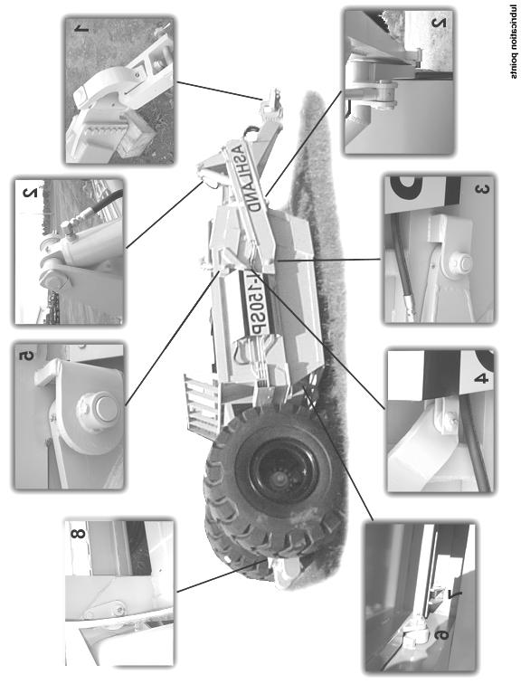
16 TORQUE SPECIFICATIONS LUBRICATION 1. Grease all zerks every 8 hrs of operation with high quality, general-purpose grease. a) Grease until grease flows from around pin. Lubrication Points (see Ill. on next page) 1. Hitch Horizontal and vertical pins. 2. Lift Cylinders Rod end & base end; Both left & right sides. 3. Front Arm Pivot Joint Both left & right sides. 4. Apron Cylinders Rod clevis pin; Both left & right sides. 5. Apron Pivot Pin Both left & right sides. 6. Hold-down Rollers Both left & right sides. 7. Floor Rollers Both left & right sides. 8. Tapered Rollers Both left & right sides. 16
17 17
18 HYDRAULIC SYSTEM Standard Two-Circuit Hydraulic Plumbing The apron cylinders and the push-off cylinder are controlled on the same circuit with the sequence of the operation controlled by a sequence valve. The other hydraulic circuit controls the lift cylinders on the earthmover. *To adjust the sequence valve, see Troubleshooting section. Optional Three-Circuit Hydraulic Plumbing The apron cylinders, push-off cylinder, and lift cylinders are all on separate hydraulic circuits. Push-off Cylinder Hydraulic System A pressure relief valve, in both two-circuit and three-circuit hydraulic plumbing, protects the pushoff cylinder hydraulic system. This pressure relief valve is designed to limit the hydraulic oil pressure delivered to the push-off cylinder. This valve is preset from the factory at 2000 psi. *To adjust the pressure relief valve, see Troubleshooting section. CAUTION! Relieve all hydraulic pressure before working on the hydraulic system. WARNING! High Pressure Fluid Hazard To prevent serious injury or death from high pressure fluid: a) Relieve pressure on hydraulic system before repairing, adjusting, or disconnecting. b) Wear proper hand and eye protection when searching for leaks. c) Keep all components in good repair. 18

19 PUSHING THE EARTHMOVER The I-150SP was designed to be pushed when equipped with the optional push-bar. However, Ashland Industries, Inc. STRONGLY recommends using extreme caution when pushing the I-150SP earthmover to prevent any unnecessary damage. CAUTION! The I-150SP earthmover must be pushed in a straight line with a maximum of a 150 hp dozer. Do not ram or jar the earthmover while push ing and push at a constant speed. 19
20 TROUBLESHOOTING Introduction With proper care and maintenance, the I-150SP will give many years of reliable service. When a situation arises where the earthmover performance is not satisfactory, this section will give some pointers on finding and correcting the problem. Grease zerk will not take grease. 1. Grease zerk plugged. a) Remove and replace grease zerk. 2. Pin is frozen. a) Remove, clean, and inspect pin. b) Replace pin if necessary. 3. Bushing grease passage is not aligned with grease zerk. a) Remove, clean, inspect, and realign bushing. b) Replace bushing if necessary and realign. Push-off rollers do not roll. 1. The rollers need lubrication. a) Check zerk hole and grease. b) Remove pin, clean, inspect, and replace if necessary. 2. The roller bushing is worn out. a) Remove roller assembly and replace bushing. b) See parts manual. Cylinders will not hold in preset position, i.e. the cylinder creeps. 1. Seals leaking internally. a) Remove and replace seal kit. 20
 Remove the acorn nut from the end of the pressure relief valve with a ½ wrench to expose the adjustment screw.")
21 Machine cuts unevenly. 1. Cutting edges worn unevenly. a) Replace cutting edges. 2. Improperly inflated tires. a) Check air pressure in tires. Push-off cylinder stalls during ejection process. 1. Adjust pressure relief valve bypass pressure. a) Remove the acorn nut from the end of the pressure relief valve with a ½ wrench to expose the adjustment screw. Turn the adjustment screw, using a 4mm hex wrench, clockwise to increase pressure and counter-clockwise to decrease pressure. Use a pressure gauge in the hydraulic line as shown, to set the pressure. 21

22 Apron closes slowly or Apron and push-off are not working well together. 1. Sequence valve needs adjusting. a) Remove acorn nut from end of sequence valve with a ½ wrench. Turn adjustment screw, using a 4mm hex wrench, clockwise until front apron rises before the push-off advances while the earthmover is empty. Turn the adjustment screw an additional ¼ turn clockwise, then replace the acorn nut and tighten. b) Torque check valve assembly and int. pilot plug to 25 ft-lbs maximum. CAUTION! Overtightening check valve assembly and int. pilot plug will cause internal damage to the sequence valve. * Note: Check valve assembly may leak slightly when torqued to 25 ft-lbs. 22
23 Limited Warranty Statement Ashland Industries Inc. warrants each new product to be free from defects in material and workmanship. This warranty is applicable only for the normal service life expectancy of the product or components, not to exceed six consecutive months from the date of delivery of the new Ashland Industries product to the original purchaser, or the date the product is first put into service via a rental agreement or other means, whichever occurs first. Genuine Ashland Industries Inc. replacement parts and components will be warranted for 30 days from date of purchase, or the remainder of the original equipment warranty period, whichever is longer. Under no circumstances will it cover any merchandise or components thereof, which in the opinion of the company, has been subjected to misuse, unauthorized modification, alterations, an accident or if repairs have been made with parts other than those obtained through Ashland Industries Inc. Ashland Industries Inc. in no way warrants Tires since these items are warranted separately by their respective manufacturer. Please call Ashland Industries Inc. to receive phone numbers of tire suppliers. Ashland Industries Inc. in no way warrants wearable items such as cutting edges, front dolly wheel balls, socket halves. Our obligation under this warranty shall be limited to repairing or replacing, free of charge to the original purchaser, any part that, in our judgement, shall show evidence of such defect, provided further that such part shall be returned within 30 days from the date of failure to Ashland Industries Inc. routed through the dealer and distributor from whom the purchase was made, transportation charges prepaid. Upon warranty approval proper credits will be reimbursed for transportation. This warranty shall not be interpreted to render Ashland Industries Inc. liable for injury or damages of any kind or nature to person or property. This warranty does not extend to the loss revenue, extra labor cost associated with downtime, substitute machinery, rental or for any other reason. Except as set forth above, Ashland Industries Inc. shall have no obligation or liability of any kind on account of any of its equipment and shall not be liable for special or consequential damages. Ashland Industries Inc. make no other warranty, expressed or implied, and, specifically, Ashland Industries Inc. disclaims any implied warrant or merchantability or fitness for a particular purpose. Some states or provinces do not permit limitations or exclusions of implied warranties or incidental or consequential damages, so the limitations or exclusion in this warranty may not apply. This warranty is subject to any existing conditions of supply which may direct affect our ability to obtain materials or manufacture replacement parts. Ashland Industries Inc. reserves the right to make improvements in design or changes in specifications at any time, without incurring any obligation to owners of units previously sold No one is authorized to alter, Modify or enlarge this warranty nor the exclusion, limitations and reservations. 23 Ashland Industries Inc. Warranty Department
I-130 XL PARTS MANUAL Introduced 4/01/01
 I-130 XL PARTS MANUAL Introduced 4/01/01 Ashland Industries Inc. Hwy. 13 South P.O. Box 717 Ashland, WI. 54806 877-634-4622 Toll Free - phone 715-682-4622 phone 715-682-9717 fax www.ashlandind.com MODEL
MODEL I-900 SCRAPER INDEX
 I-900 PARTS MANUAL Ashland Industries Inc. Hwy. 13 South P.O. Box 717 Ashland, WI. 54806 877-634-4622 Toll Free - phone 715-682-4622 phone 715-682-9717 fax www.ashlandind.com MODEL I-900 SCRAPER HOW TO
I-150SP PARTS MANUAL
 I-150SP PARTS MANUAL Version 6-04 Ashland Industries Inc. 1115 Rail Drive P.O. Box 717 Ashland, WI. 54806 Ph: 877-634-4622 Toll Free Ph: 715-682-4622 Fx: 715-682-9717 www.ashlandind.com HOW TO ORDER PARTS:
I-110 PARTS MANUAL Updated 3/21/01
 I-110 PARTS MANUAL Updated 3/21/01 Ashland Industries Inc. Hwy. 13 South P.O. Box 717 Ashland, WI. 54806 877-634-4622 Toll Free - phone 715-682-4622 phone 715-682-9717 fax www.ashlandind.com MODEL I-100,
I-130TS PARTS MANUAL
 I-130TS PARTS MANUAL Version 3-03 Ashland Industries Inc. 1115 Rail Drive P.O. Box 717 Ashland, WI. 54806 Ph: 877-634-4622 Toll Free Ph: 715-682-4622 Fx: 715-682-9717 www.ashlandind.com Model I-130TS Scraper
I-175 PARTS MANUAL Version 4-04
 I-175 PARTS MANUAL Version 4-04 Ashland Industries Inc. 1115 Rail Drive P.O. Box 717 Ashland, WI. 54806 Ph: 877-634-4622 Toll Free Ph: 715-682-4622 Fx: 715-682-9717 www.ashlandind.com Model I-175 Scraper
Model 35 PARTS MANUAL
 Model 35 PARTS MANUAL Version 3-2007 Ashland Industries Inc. 1115 Rail Drive P.O. Box 717 Ashland, WI. 54806 Ph: 877-634-4622 Toll Free Ph: 715-682-4622 Fx: 715-682-9717 www.ashlandind.com Model 35 Scraper
HOW TO ORDER PARTS: Unless this is done, we cannot provide prompt service or assure shipment of the correct parts.
 HOW TO ORDER PARTS: IMPORTANT Parts must be ordered through your local authorized ASHLAND dealer. Be sure to state MODEL and SERIAL NUMBER of your machine, PART NUMBER, DESCRIPTION and QUANTITY needed.
HOW TO ORDER PARTS: Unless this is done, we cannot provide prompt service or assure shipment of the correct parts.
 How to Order Parts HOW TO ORDER PARTS: IMPORTANT Parts must be ordered through your local authorized ASHLAND dealer. Be sure to state MODEL and SERIAL NUMBER of your machine, PART NUMBER, DESCRIPTION and
I-130XL2 PARTS MANUAL
 EARTHMOVERS I-130XL2 PARTS MANUAL ver 0309-22128 Inc. 1115 Rail Drive P.O. Box 717 Ashland, WI. 54806 Ph: 877-634-4622 Toll Free Ph: 715-682-4622 Fx: 715-682-9717 www.ashlandind.com How to Order Parts
I-175XL2 PARTS MANUAL
 I-175XL2 PARTS MANUAL I-175XL2 ver 5-06 Ashland Industries Inc. 1115 Rail Drive P.O. Box 717 Ashland, WI. 54806 Ph: 877-634-4622 Toll Free Ph: 715-682-4622 Fx: 715-682-9717 www.ashlandind.com HOW TO ORDER
EARTHMOVERS I-110XL2 PARTS MANUAL. ver
 EARTHMOVERS I-110XL2 PARTS MANUAL ver 1108-22103 Inc. 1115 Rail Drive P.O. Box 717 Ashland, WI. 54806 Ph: 877-634-4622 Toll Free Ph: 715-682-4622 Fx: 715-682-9717 www.ashlandind.com How to Order Parts
EARTHMOVERS I-110XL2 PARTS MANUAL. ver
 EARTHMOVERS I-110XL2 PARTS MANUAL ver 0109-22128 Inc. 1115 Rail Drive P.O. Box 717 Ashland, WI. 54806 Ph: 877-634-4622 Toll Free Ph: 715-682-4622 Fx: 715-682-9717 www.ashlandind.com How to Order Parts
I-950 PARTS MANUAL. Ver. 1010
 I-950 PARTS MANUAL Ver. 1010 Ashland Industries Inc. ive Ashland, WI. 54806 Ph: 877-634-4622 Toll Free Ph: 715-682-4622 Fx: 715-682-9717 www.ashlandind.com Serial Number WELCOME TO OUR NEW CUSTOMERS! Thank
I-950 PARTS MANUAL. Ver. 0610
 I-950 PARTS MANUAL Ver. 0610 Ashland Industries Inc. ive Ashland, WI. 54806 Ph: 877-634-4622 Toll Free Ph: 715-682-4622 Fx: 715-682-9717 www.ashlandind.com WELCOME TO OUR NEW CUSTOMERS! Thank you for your
MODEL 45 SCRAPER INDEX
 MODEL 45 SCRAPER HOW TO ORDER PARTS: Be sure to state MODEL and SERIAL NO. of machine, PARTS NO., DESCRIPTION, and QUANTITY wanted. Unless this is done, we cannot provide prompt service or assure shipment
Ashland I-200TS4. Earthmovers. Parts Manual. Ashland Industries. Crafting Quality since 1953! ver. 0612
 Ashland Earthmovers I-200TS4 Parts Manual ver. 0612 Ashland Industries Crafting Quality since 1953! 1115 Rail Drive P.O. Box 717 Ashland, WI U.S.A. Toll Free: (877) 634-4622 Business: (715) 682-4622 Fax:
Table of Contents Categorized Listing
 ASHLAND SCRAPERS 1 Welcome and Serial Number 2500SS 1 Safety Guidelines 2 Assembly - 2500SS-002 3 Actuating Frame - 2500SS 4 Apron - 2500SS 5 Apron - 2500SS - (breakout) 6 Beam & Hub - 2500SS 7 Bowl -
Operation and Parts Manual
 Operation and Parts Manual 3-Point PTO and Hydraulic Stump Grinders Models: SC-25 and SC-25H SC-50 and SC-50H Safety Operation Maintenance Repair Troubleshooting Parts Parts SC-50 and SC-50-H Stumpbuster
MODEL 25 SCRAPER INDEX
 MODEL 25 SCRAPER HOW TO ORDER PARTS Be sure to state MODEL and SERIAL NO. of machine, PARTS NO., DESCRIPTION, and QUANTITY wanted. Unless this is done, we cannot give you prompt service or send the correct
Table of Contents Alphabetized Listing
 A Apron Assembly (130-1020) 8 Apron Cylinder (#A125050) 4" X 13" 17 ASHLAND SCRAPERS 1-35 Assembly - Push Off (110-130) 11 Assembly - Wheel Front (130) 14 Assembly - Wheel Rear (130X) Optional 16 B Bowl
MODEL L-9, L-10 LAND LEVELER INDEX
 HOW TO ORDER PARTS: MODEL L-9, L-10 LAND LEVELER Be sure to state MODEL and SERIAL NO. of machine, PARTS NO., DESCRIPTION, and QUANTITY wanted. Unless this is done, we cannot provide prompt service or
Table of Contents Categorized Listing
 1 Introduction 1 Operation and Maintenance 2 Safety Guidelines 5 Assembly - Main - WG-25-2-002 6 Actuating Frame - 600988 7 Apron & Bucket-25CS 8 Bowl - 25CS 9 Frame - 601086 10 Wheel Assembly - 25 11
Table of Contents Categorized Listing
 1 Serial Number 1 How to Order Parts 2 Parts - Transport Locks (18HD) 3 Instruction: Operation and Maintenance 4 Instruction: Operation and Maintenance 5 Safety Guidelines 7 CS18HD Assembly 8 Front Frame
SHEYENNE TELE-BOOM OWNERS MANUAL OPERATOR INSTRUCTIONS PARTS BOOK
 SHEYENNE TELE-BOOM OWNERS MANUAL OPERATOR INSTRUCTIONS PARTS BOOK 701 Lenham Ave. SW PO Box 647 Cooperstown ND 58425 1-800-797-1883 701-797-2700 * 701-797-2584 Fax www.sheyennemfg.com TABLE OF CONTENTS
Parts Manual 25CS WG-25CS PH:
 Parts Manual 25CS WG-25CS-002 10-18 1 Table of Contents Introduction 3 Scraper Specifications 4 Assembly 5 Frame 6 Frame Expanded 7 Wheel Assembly 8 Apron 9 Apron Expanded 10 Bowl 11 Actuating Frame 12
OPERATION AND MAINTENANCE MANUAL WASP, Inc. United Airlines Shock Mount Cargo Cart Model No. A03439D
 OPERATION AND MAINTENANCE MANUAL WASP, Inc. United Airlines Shock Mount Cargo Cart Model No. A03439D WASP RECORD OF REVISIONS REV. ISSUE DATE BY REV. ISSUE DATE BY NO. DATE INSERTED NO. DATE INSERTED Original
Parts Manual 2500SS WG-GH PH:
 Parts Manual 2500SS WG-GH2500-004 11-18 1 Table of Contents Introduction 3 Scraper Specifications 4 Assembly 5 Frame 6 Frame Expanded 7 Oscillating Beam 8 Wheel Assembly 9 Apron 10 Apron Expanded 11 Actuating
Parts Manual HDW WG-HDW /18 S.N PH:
 Parts Manual HDW-3217-18 WG-HDW3217-18 10/18 S.N. 24715+ 1 Table of Contents Introduction 3 Disc Harrow Specifications 4 Frame 5 Lift Cylinder 8 Disc Gang 9 Jack 10 Oil Bath Bearing 11 Wheel Carriage Assembly
Parts Manual 2500SS WG-GH PH:
 Parts Manual 2500SS WG-GH2500-002 5-18 1 Table of Contents Introduction 3 Scraper Specifications 4 Assembly 5 Frame 6 Frame Expanded 7 Oscillating Beam 8 Wheel Assembly 9 Apron 10 Apron Expanded 11 Actuating
SCHMEISER TILL AN PAK HYDRAULIC TRANSPORT KITS ASSEMBLY & PARTS MANUAL
 SCHMEISER TILL AN PAK HYDRAULIC TRANSPORT KITS ASSEMBLY & PARTS MANUAL T.G. SCHMEISER CO., INC. P.O. BOX 07 FRESNO, CA. 97 (559) - FAX (559) -79 www.tgschmeiser.com VERSION.a 0-0 COPYRIGHT 0 T.G.SCHMEISER
Parts Manual 155XL2 WG-155X /18 PH:
 Parts Manual 155XL2 WG-155X-001 10/18 1 Table of Contents Introduction 3 Scraper Specifications 4 Assembly 5 Bowl 6 Rear Wheel Assembly 8 Pushoff 9 Apron 11 Front Section 12 Ball/Socket Assembly 13 Pole
Parts Manual 155TS2 WG-155T-R /18 PH:
 Parts Manual 155TS2 WG-155T-R-002 10/18 1 Table of Contents Introduction 3 Scraper Specifications 4 Assembly 5 Ashland Hitch 6 Bowl 7 Wheel Assembly 9 Pushoff 10 Apron 12 Front Section 13 Lift Cylinder
MODEL HD-BTC. Installation, Operation & Repair Parts Information REV041416
 MODEL HD-BTC Installation, Operation & Repair Parts Information REV041416 TABLE OF CONTENTS SAFETY INSTRUCTIONS 1 DEFINITIONS 1 SPECIFICATIONS 2 INSTALLATION INSTRUCTIONS 2 OPERATING INSTRUCTIONS 2 MAINTENANCE
SCHMEISER BANTAM LEVELER ASSEMBLY & PARTS MANUAL T. G. SCHMEISER CO., INC.
 SCHMEISER BANTAM LEVELER ASSEMBLY & PARTS MANUAL T. G. SCHMEISER CO., INC. P.O. BOX 07 FRESNO, CA 937-07 (559) 68-88 FAX (559) 68-379 www.tgschmeiser.com VERSION.3 OCTOBER 03 COPY RIGHT 03 T.G.SCHMEISER
SHEYENNE TELE-SAW MODEL 21 OWNERS MANUAL OPERATOR INSTRUCTIONS PARTS BOOK
 SHEYENNE TELE-SAW MODEL 21 OWNERS MANUAL OPERATOR INSTRUCTIONS PARTS BOOK 701 Lenham Ave. - P.O. Box 647 Cooperstown, ND 58425 Office (701) 797-2700 Fax (701) 797-2584 Toll Free (800) 797-1883 www.sheyennemfg.com
4200 & 6200 Owner s Manual & Parts Book
 00 & 00 Owner s Manual & Parts Book Purchase Date Serial Number Model Number Tractor Model PN: - Dealer Date --0 Description Page To The Owner & Maintenance Safety Precautions & Torque Specifications Skid
OPERATION AND MAINTENANCE MANUAL WASP, Inc. 757 Towbar Model No. A01568D
 OPERATION AND MAINTENANCE MANUAL WASP, Inc. 757 Towbar Model No. A01568D WASP RECORD OF REVISIONS REV. ISSUE DATE BY REV. ISSUE DATE BY NO. DATE INSERTED NO. DATE INSERTED Original May 19/97 001 June 10/03
Warranty Information Operators Manual Installation Instructions. Sudenga
 Warranty Information Operators Manual Installation Instructions Sudenga Rust Sales, Inc. 2964 164 th Ave SE Harwood, ND 58042 (800) 478-7801 (701) 282-9194 www.hopperwalker.com Limited Warranty Statement
Parts Manual 220TS4 WG-220T PH:
 Parts Manual 220TS4 WG-220T-4-005 5-18 1 Table of Contents Introduction 3 Scraper Specifications 4 Assembly 5 Ashland Hitch 6 Bowl 7 Wheel Assembly 10 Pushoff 12 Apron 14 Front Section 15 Apron Cylinder
Parts Manual 215TS2 WG-215T PH:
 Parts Manual 215TS2 WG-215T-004 10-18 1 Table of Contents Introduction 3 Scraper Specifications 4 Assembly 5 Ashland Hitch 6 Bowl 7 Wheel Assembly 10 Pushoff 12 Apron 14 Front Section 15 Apron Cylinder
GRADER BLADE ASSEMBLY & PARTS MANUAL
 SCHMEISER GRADER BLADE ASSEMBLY & PARTS MANUAL UP TO 0 FT. WIDE T. G. SCHMEISER CO., INC. P.O. BOX 07 FRESNO, CA 937-07 (9) - FAX (9) -379 VERSION. 0 03 COPYRIGHT 03 T.G.SCHMEISER CO., INC INTRODUCTION
MODEL EF Full Circle Tire Spreader
 MODEL EF Full Circle Tire Spreader Installation, Operation & Repair Parts Information Branick Industries, Inc. 4245 Main Avenue P.O. Box 1937 Fargo, North Dakota 58103 REV. 062917 P/N: 81-0050C CAUTION
450 & Slant Top Owner s Manual & Parts Book
 0 & 0 - Slant Top Owner s Manual & Parts Book Purchase Date Serial Number Model Number Tractor Model PN: - Dealer Date -- Contents Description Page To The Owner & Maintenance Safety Precautions & Torque
Parts Manual 2012CS WG-2012-CS-4-001
 Parts Manual 2012CS WG-2012-CS-4-001 4-18 Table of Contents Introduction 3 Scraper Specifications 4 Assembly 5 Ashland Hitch 6 Bowl 7 Apron 8 Front Section 10 Optional - Laser Mast 12 Rear Section 13 Wheel
MODEL 5120 Tire Repair Station
 MODEL 5120 Tire Repair Station 00-0049 Installation, Operation & Repair Parts Information Branick Industries, Inc. 4245 Main Avenue P.O. Box 1937 Fargo, North Dakota 58103 REV01182017 P/N: 81-0058G CAUTION
LIMITED WARRANTY DISCLAIMER OF IMPLIED WARRANTIES & CONSEQUENTIAL DAMAGES
 Published 08/15 LIMITED WARRANTY Bush Hog warrants to the original purchaser of any new Bush Hog equipment, purchased from an authorized Bush Hog dealer, that the equipment be free from defects in material
Parts Manual 2014CS WG-2014-CS PH:
 Parts Manual 2014CS WG-2014-CS-6-003 11-18 24591+ 1 Table of Contents Introduction 3 Scraper Specifications 4 Assembly 5 Ashland Hitch 6 Bowl 7 Apron 8 Front Section 10 Optional Laser Mast 12 Rear Section
SCHMEISER VARITRAK LAND LEVELER ASSEMBLY & PARTS MANUAL
 SCHMEISER VARITRAK LAND LEVELER ASSEMBLY & PARTS MANUAL, 0, & FT. WIDE T. G. SCHMEISER CO., INC. P.O. BOX 07 FRESNO, CA 937-07 (559) - FAX (559) -379 www.tgschmeiser.com VERSION. 00 COPYRIGHT 00 T.G.SCHMEISER
TABLE OF CONTENTS. Warranty Disclaimers Delivery Checklist After Sale Checklist Safety Set Up... 8
 TABLE OF CONTENTS Pickett Equipment Warranty... 2 Warranty Disclaimers... 3 Delivery Checklist... 4 After Sale Checklist... 4 Safety... 5-7 Set Up... 8 Machine Adjustments and Operation... 9 Maintenance
MODELS CX10 and CX20 INDUSTRIAL PUMPS INSTRUCTIONS AND SERVICE MANUAL
 MODELS CX0 and CX20 INDUSTRIAL PUMPS INSTRUCTIONS AND SERVICE MANUAL NOTE! To the installer: Please make sure you provide this manual to the owner of the equip ment or to the responsible party who maintains
REPAIR PARTS LIST ASSEMBLY AND OPERATING INSTRUCTIONS ROME. BH Series. Hinge-Wheel Combination Harrows
 REPAIR PARTS LIST ASSEMBLY AND OPERATING INSTRUCTIONS ROME BH Series FORM NO. 00B HingeWheel Combination Harrows BH0 BH0 BH0 BH00 BH0 BH0 Effective Serial BH000 and Up. Effective Serial BH000 and Up. Effective
Parts Book 612N, 812N, 642N, 842N, 862N 714NT, 814NT, 742NT, 842NT, 862NT
 Parts Book 612N, 812N, 642N, 842N, 862N 714NT, 814NT, 742NT, 842NT, 862NT Wishek Mfg. LLC 112 South 2nd Street PO Box 185 Wishek, ND 58495 (701) 452-2449 www.wishekmfg.com WARRANTY/ PARTS RETURN POLICY
Westfield, Mayrath, Hutchinson, Wheatheart
 Warranty Information Operators Manual Installation Instructions Westfield, Mayrath, Hutchinson, Wheatheart Rust Sales, Inc. 2964 164 th Ave SE Harwood, ND 58042 (800) 478-7801 (701) 282-9194 www.hopperwalker.com
OPERATORS MANUAL SAFETY & WARRANTY SECTION
 OPERATORS MANUAL SAFETY & WARRANTY SECTION KMW Ltd. 198 N. Hwy 281 Great Bend, Kansas 67530 800 445-7388 Fax 620 793-6737 ïïïkâãïäç~çéêëkåçã SAFETY FIRST This symbol, the industry s Safety Alert Symbol,
WARRANTY REGISTRATION AND POLICY
 WARRANTY REGISTRATION AND POLICY Buhler Manufacturing products are warranted for a period of twelve (12) months from original date of purchase, by original purchaser, to be free from defects in material
Operator s Manual & Repair Parts Manual. Do Not Use or Operate This Equipment Until You Have Read and Understand This Manual
 Operator s Manual & Repair Parts Manual Do Not Use or Operate This Equipment Until You Have Read and Understand This Manual The purpose of this manual is to explain maintenance requirements and adjustments
Lubricator Gun: 10,000 psi (700 bar) Maximum Delivery Pressure when disconnected from Dispenser
 Maximum Delivery Pressure when disconnected from Dispenser") INSTRUCTIONS-PARTS LIST 30 455 INSTRUCTIONS This manual contains important warnings and information. READ AND KEEP FOR REFERENCE. Rev. C Supercedes B Hand-Operated Portable Grease Dispenser Buckshot Luber
INSTRUCTIONS-PARTS LIST 30 455 INSTRUCTIONS This manual contains important warnings and information. READ AND KEEP FOR REFERENCE. Rev. C Supercedes B Hand-Operated Portable Grease Dispenser Buckshot Luber
4750 Drill. Repair Parts
 4750 Drill Repair Parts #615997-2016 Identification Your CrustBuster drill is identified by a Serial Number and Model Number. Record these numbers in the spaces provided in this manual and refer to them
LUBRICATOR GUN INSTRUCTIONS-PARTS LIST. 10,000 psi (700 bar) Maximum Delivery Pressure. Detachable-type
 Maximum Delivery Pressure. Detachable-type") INSTRUCTIONS-PARTS LIST 306 460 INSTRUCTIONS This manual contains important warnings and information. READ AND KEEP FOR REFERENCE. Rev. E Supercedes D Detachable-type LUBRICATOR GUN 10,000 psi (700 bar)
INSTRUCTIONS-PARTS LIST 306 460 INSTRUCTIONS This manual contains important warnings and information. READ AND KEEP FOR REFERENCE. Rev. E Supercedes D Detachable-type LUBRICATOR GUN 10,000 psi (700 bar)
DISC HARROW PART'S MANUAL DHP8/10/12. RHINO 1020 S. Sangamon Ave. Gibson City, IL
 DISC HARROW DHP8/10/12 Published 03/16 PART'S MANUAL P/N 00789085P An Operator's Manual was shipped with the equipment in the Manual Canister. This Operator's Manual is an integral part of the safe operation
Instruction Manual and Parts List
 Instruction Manual and Parts List KW Products Inc. Copyright 2003, All Rights Reserved Equipment, specifications, options and accessories subject to change without notice Part #108-3050-32 521 WARRANTY
Thatching Reel Reelmaster 450 D, 4500 D, 335 D & 3500 D
 Form No. 3350 8 Thatching Reel Reelmaster 450 D, 4500 D, 335 D & 3500 D Model No. 0373 Serial No. 5000000 and Up Model No. 03730 Serial No. 5000000 and Up Operator s Manual English (EN) Introduction Read
MODEL 5500 Tire Repair Station
 MODEL 5500 Tire Repair Station Installation, Operation and Repair Parts Information Branick Industries, Inc. 4245 Main Ave P.O. Box 1937 Fargo, North Dakota 58103 P/N: 81-0047C TABLE OF CONTENTS SAFETY
HSIV PLOW OPERATOR S MANUAL
 PLOW RWF INDUSTRIES 873 Devonshire Ave., Woodstock, Ontario N4S 8Z4 Tel: (519) 421-0036 Toll Free: 1-800-263-1060 Fax: (519) 421-0028 Email: parts@rwfbron.com JANUARY 2015 THE INFORMATION CONTAINED IN
Operator s/parts Manual
 1--1 4/8/04 Operator s/parts Manual 30 3-Section Flat Fold Marker Manufacturing, Inc. P.O. Box 5060 Salina, Kansas 67402-5060! Read the Operator s manual entirely. When you see this symbol, the subsequent
John Deere Tractors MANUAL
 John Deere 800-820 Tractors MANUAL 202 John Deere 800-820 Tractors Blade, pivot frame Cylinders & Hydraulics Main Frame, Brackets, Mounting Safety, Operation, Maintenance 9 Attachments Warranty 2 22 Industrial
MODEL L/R/EF Sectional Tire Spreader
 MODEL L/R/EF Sectional Tire Spreader Installation, Operation & Repair Parts Information Branick Industries, Inc. 4245 Main Avenue P.O. Box 1937 Fargo, North Dakota 58103 REV08032016 P/N: 81-0195E TABLE
PARTS CATALOG FOR. Mud Hog Rear Wheel Drive FOR. MF 9540/9550/9560, CAT 540C/550C/560C, Gleaner A540/A560, Fendt 6450R/9480R COMBINES
 PARTS CATALOG FOR Mud Hog Rear Wheel Drive FOR MF 9540/9550/9560, CAT 540C/550C/560C, Gleaner A540/A560, Fendt 6450R/9480R COMBINES Mud Hog Model Number: AG9896 A Product of Tuthill Drive Systems P.O.
Operation & Service Manual
 Operation & Service Manual Model: 02-1248-0112 12 Ton Single Stage Jack 11/2004 Rev. 02 Includes Illustrated Parts Lists 1740 Eber Rd Tronair, Inc. Phone: (419) 866-6301 Holland, OH 43528-9794 www.tronair.com
OWNER/OPERATOR MANUAL. Airmotor effective dia. in. 2.5
 MODELS 282050, 282716 & 283513 AIR OPERATED CHASSIS PUMP SERIES A OWNER/OPERATOR MANUAL SPECIFICATIONS Airmotor effective dia. in. 2.5 Airinlet Material outlet 1/4 NPTF 1/4 NPTF Liquid to Air Pressure
4745 Drill OWNER'S MANUAL (06-08) #
 #") 4745 Drill OWNER'S MANUAL (06-08) # 605865 Identification Your CrustBuster drill is identified by a Serial Number and Model Number. Record these numbers in the spaces provided in this manual and refer
4745 Drill OWNER'S MANUAL (06-08) # 605865 Identification Your CrustBuster drill is identified by a Serial Number and Model Number. Record these numbers in the spaces provided in this manual and refer
Planting Components. Operator s/parts Manual
 Operator s/parts Manual Unit Mount Conservation Coulter and Spring Package Attachment for JD 7000, JD 7200, White 6100, Kinze Planters and Great Plains Row Units Planting Components! Read the operator
TABLE OF CONTENTS DESCRIPTION. Safety Instructions & Safety Sign Locations Operating Instructions Assembly Instructions...
 TABLE OF CONTENTS DESCRIPTION PAGE Warranty... 1 Safety Instructions & Safety Sign Locations... 2 Operating Instructions... 3 Assembly Instructions... 5 500 & 600 Snowblower Drawings... 8 500 & 600 Snowblower
Multi-Ject Aerator Model no.: BA-400 Operation & Parts Manual
 Multi-Ject Aerator Model no.: BA-400 Operation & Parts Manual P a g e 2 Table of Contents Cover Page 1 Table of Contents 2 Welcome to Bannerman 3 Warranty 4 Work Safety 5 Three Point Hitch Attachment Procedure
Planting Components. Operator s/parts Manual Heavy Duty Fertilizer Coulter
 Operator s/parts Manual Heavy Duty Fertilizer Coulter Planting Components Read the operator manual entirely. When you see this symbol, the subsequent instructions and warnings are serious - follow without
WARRANTY REGISTRATION AND POLICY
 WARRANTY REGISTRATION AND POLICY Buhler Manufacturing products are warranted for a period of twelve (12) months from original date of purchase, by original purchaser, to be free from defects in material
GrabTec. Farm Grapple OWNER S MANUAL. GF and GFD Models
 Farm Grapple OWNER S MANUAL GF and GFD Models Grabtec Inc May 2014 Install Center/Shipping/Receiving: 1242 Arizona Ave Larchwood, IA 1241 (888) 87-892 (712) 477-267 PREFACE This manual describes the installation,
Operating Instructions and Parts Manual Long Chassis Service Jacks
 Operating Instructions and Parts Manual Long Chassis Service Jacks Models JSJ-3T/JSJ-5T/JSJ-10T WMH TOOL GROUP 2420 Vantage Drive Elgin, Illinois 60123 Part No. M-454430 Ph.: 800-274-6848 Revision A 8/05
RMH1000M-HD ROUND MODULE HANDLER
 RMH000M-HD ROUND MODULE HANDLER CAT90 9th EDITION Beginning Serial No: 0000 Owner's Name Dealer's Name Serial Number Date Purchased Model No. TABLE OF CONTENTS CAT90 9th Edition January, 08 RMH000M-HD
AEROTHATCH 83/SEEDER 93
 FORM NO. 01-505-0110 Rev. B MODEL NO. 44830-20101 & UP MODEL NO. 44831-20101 & UP MODEL NO. 44835-40162 & UP PARTS CATALOG AEROTHATCH 83/SEEDER 93 AEROTHATCH 83 - MODEL NO. 44830 & 44831 MAIN FRAME ASSEMBLY
OPERATING, SERVICE AND MAINTENANCE MANUAL MODEL SCH 2900 MODEL SCH 3600 MODEL SCH 4900 PLANETARY WINCHES
 OPERATING, SERVICE AND MAINTENANCE MANUAL MODEL SCH 2900 MODEL SCH 3600 MODEL SCH 4900 PLANETARY WINCHES CAUTION: READ AND UNDERSTAND THIS MANUAL BEFORE INSTALLATION AND OPERATION OF WINCH. SEE WARNINGS!
Planting Components. Operator s/parts Manual Vantage II
 Operator s/parts Manual Vantage II Planting Components! Read the operator s manual entirely. When you see this symbol, the subsequent instructions and warnings are serious - follow without exception. Your
New Holland TG S.S.
 Mid-Mount New Holland TG210-285 S.S. Tractors MANUAL Mid-Mount New Holland TG210-285 S.S. Tractors Blade, pivot frame 1 Cylinders & Hydraulics 3 Main Frame, Brackets, Mounting 5 Safety, Operation, Maintenance
Mulching and Finishing Mowers MP and FP
 Mulching and Finishing Mowers MP and FP Parts Manual Locke Turf 0 Highway E, Opp, Alabama, () -00 Transport Wheel, Tire & Spindle MP and FP ALPHABETICAL INDEX CONTENTS PAGE 00 Hydraulic Cylinder (Rear)
POST HOLE DIGGER. Operation, Service & Parts Manual For Models D20 & D40. FORM: D20_40DigRev.QXD
 POST HOLE DIGGER Operation, Service & Parts Manual For Models D20 & D40 FORM: D20_40DigRev.QXD September 2006 Revised August 2009 TABLE OF CONTENTS Introduction.............................1 Preparation..............................2
DIAMOND CONCRETE SAW PARTS LIST MODEL CC8000 P R O D U C T S. (Revised )
") DIAMOND P R O D U C T S CONCRETE SAW PARTS LIST MODEL CC8000 (Revised 10-15-2002) Table of Contents Page Saw Controls Legend. 3 Drawing 1. Frame Group. 4-5 Drawing 2. Arm Assembly... 6-7 Drawing 3. Hydraulics
DIAMOND P R O D U C T S CONCRETE SAW PARTS LIST MODEL CC8000 (Revised 10-15-2002) Table of Contents Page Saw Controls Legend. 3 Drawing 1. Frame Group. 4-5 Drawing 2. Arm Assembly... 6-7 Drawing 3. Hydraulics
OWNER S GUIDE 8A DURALIFT II 13,200 LB. CAPACITY. Link Mfg. Ltd th St. N.E. Sioux Center, IA USA
 OWNER S GUIDE 8A000715 DURALIFT II 13,200 LB. CAPACITY Link Mfg. Ltd. 223 15th St. N.E. Sioux Center, IA USA 51250-2120 www.linkmfg.com QUESTIONS? CALL CUSTOMER SERVICE 1-800-222-6283 DEALER / INSTALLER:
Product Parts Information
 Product s Information Second Generation Liftchain Industrial Air Hoist Models LC2A015S and LC2A030D (Dwg. MHP2659) Save These Instructions Form MHD56297 Edition 1 October 2004 71441307 2004 Ingersoll-Rand
CRD610 Automatic Fitting Inserter
 CRD610 Automatic Fitting Inserter OPERATIONS MANUAL VERSION 1.2 LAST EDITED 12.12.2018 cleanroomdevices.com 1 Table of Contents Title Page. 1 Table of Contents...2 1.0 General Product & Safety Information....3
RIGID WHEEL OFFSET DISC HARROW MODEL TRCW-12 & TRCW-16
 S MANUAL RIGID WHEEL OFFSET DISC HARROW MODEL TRCW & TRCW FORM : 00 PUBLISHED DATE: 0//0 TABLE OF CONTENTS PRODUCT IDENTIFICATION. RH0 DRAWBAR ASSEMBLY COMPLETE TRCW... YH00 DRAWBAR ASSEMBLY COMPLETE TRCW
CDS-JOHN BLUE COMPANY
 HYDRAULIC DRIVE KIT FOR VARIABLE RATE OR MANUAL CONTROL SYSTEMS PARTS AND INSTALLATION MANUAL CDS-JOHN BLUE COMPANY DIVISION OF ADVANCED SYSTEMS TECHNOLOGY, INC. 290 Pinehurst Drive - Huntsville, Alabama
Part Number: MODEL NUMBER: Rev. 7
 609 & 6 POWER BACKHOES PARTS MANUAL SERIAL NUMBER: Manual Number: PM557 Part Number: 75457 MODEL NUMBER: Rev. 7 800-922-298 I www.paladinbrands.com P.O. Box 266, Delhi, IA 5222-0266, United States of America
Pro Shot Grease Dispense Valve
 Instructions Parts List Pro Shot Grease Dispense Valve 309032J For high pressure grease dispense. 8000 psi (55 MPa, 552 bar) Maximum Working Pressure Model No. 242055, Series B, 1/4 npt Fluid Inlet Model
WISHEK WARRANTY PROGRAM
 TABLE OF CONTENTS WARRANTY (All Models)..3 SPECIFICATIONS (All Models).4 SAFETY RULES (All Models).5-7 BREAK-IN PERIOD (All Models)......8 DEPTH CONTROL (All Models)....8 TRANSPORTING (All Models)......8
OWNER'S MANUAL L A W N R O L L E R PRT-481S BH. Safety Assembly Operation Repair Parts Maintenance. Visit us on the web!
 OWNER'S MANUAL L A W N R O L L E R ROLLER MODEL: PRC- BH PRT- BH PRT-S BH PRT-S BH Safety Assembly Operation Repair Parts Maintenance Recommended for use with Riding Mowers, Lawn or Garden Tractors, and
BUSH HOG LAND MAINTENANCE REPAIR PARTS MANUAL MODEL: TD-1100 SECTION: 66
 BUSH HOG LAND MAINTENANCE REPAIR S MANUAL MODEL: TD-00 SECTION: 0 Griffin Ave. Selma, AL 0 () - () -00 Parts Ordering -00-0- Fax -00-- www.bushhog.com BUSH HOG/ LAND MAINTENANCE REPAIR S MANUAL JUNE, 00
Revised Part No. 4928WP PART'S MANUAL
 DYNA-MASTER Revised 09-14-01 Part No. 4928WP PART'S MANUAL An Operator's Manual was shipped with the equipment in the Manual Canister. This Operator's Manual is an integral part of the safe operation of
2720/12720 PARTS MANUAL 72A SECTION FLEX WING ROTARY MOWER
 0/0 This Manual applies to models 0 and 0 that use a blade pan which measures. blade hole center to blade hole center. Also blades measure 8. from hole center to blade tip. See Section if these dimensions
CDS-JOHN BLUE COMPANY
 HYDRAULIC DRIVE KIT FOR VARIABLE RATE OR MANUAL CONTROL SYSTEMS PARTS AND INSTALLATION MANUAL BarMount Bracket DirectDrive Bracket CDSJOHN BLUE COMPANY DIVISION OF ADVANCED SYSTEMS TECHNOLOGY, INC. 290