2012 NISSAN 370Z / NISMO INTERCOOLED SUPERCHARGER INSTALLATION INSTRUCTIONS
|
|
|
- Howard Sparks
- 5 years ago
- Views:
Transcription

1 2012 NISSAN 370Z / NISMO INTERCOOLED SUPERCHARGER INSTALLATION INSTRUCTIONS STEVE MILLEN SPORTPARTS, INC. All rights reserved. No part of this publication may be reproduced, transcribed, transmitted, or translated into another language in any form, by any means without written permission of STEVE MILLEN SPORTPARTS, INC. REV. E
2 Congratulations on your purchasing the STILLEN supercharger system for your 370Z For the smoothest installation and best performance and reliability from your supercharger, please follow these simple points. Read all the instructions to familiarize yourself with various parts and operations. A list of supplied parts is located on the back pages of these instructions. Check the oil in your supercharger every 2,500 miles. The initial fluid change should be done 2,500 miles after install and then every 7,500 miles Some parts on the list are already assembled, torqued and sealed, DO NOT DISASSEMBLE UNLESS INSTRUCTED TO DO SO. If any parts are missing or damaged, please call us immediately. Gather all required tools and supplies before starting installation. Use 91 octane or higher fuel. Fuel quality will vary depending on manufacturer, always use quality fuel. This kit is designed for stock engines. If the engine is modified in any way, contact STILLEN to discuss any conflicts or issues that could affect the superchargers performance. Aftermarket re-calibration devices that modify the fuel or spark curve are not recommended and may cause engine damage or failure. This STILLEN supercharger system is intended to be installed on a well maintained, healthy engine. We do not recommend installing this system on a sick or damaged engine, this can result in premature engine failure and possible supercharger failure. Stillen is not responsible for damages due to improper installation or damages due to installation on worn or damaged engines. Do not alter, modify, or adjust the STILLEN supercharger system in any way, shape or form. Unauthorized changes to boost levels, electronics or any other system will void warranties and can cause catastrophic damage. If this system is being installed on a new vehicle it is very important that factory break-in procedures are followed to prevent any adverse affect on the vehicle. EXTREMELY IMPORTANT: To insure maximum performance and safety, boost pressure MUST be checked immediately after install. We recommend using a quality (Snap-0n,AEM, HKS etc) calibrated boost/pressure gauge that reads 10-15psi (1 BAR) maximum if analog or a digital gauge. The gauge must be T eed into the small front vacuum line that leads to the supercharger bypass valve. Maximum boost reading will be obtained at WOT in 3 rd 7000 rpm. We suggest you avoid hitting the RPM limiter or an incorrect reading will result. A dynamometer can be used if traffic conditions or an off road location is not available for proper testing. The boost reading should be from psi. Pressure can vary due to atmospheric conditions and dyno types. For example a Dynojet dyno boost reading will be.3-.4 low as compared to actual road testing. Make sure to do 2-3 tests and write down your results to confirm an accurate reading. If outside the recommended pressure readings please contact Stillen technical support immediately for further assistance Page 2 of 38
3 WARNING: WE STRONGLY URGE THAT YOU REFER THIS INSTALLATION TO AN ASE CERTIFIED MECHANIC WITH EXPERIENCE IN THIS TYPE OF INSTALLATION. FAILURE TO DO SO COULD LIMIT YOUR TECH SUPPORT AND AFFECT YOUR WARRANTY. YOU NEED TO MAKE SURE YOU HAVE THE TUNE FOR YOUR VEHICLE BEFORE INSTALLING THE SUPERCHARGER!!READ THE PROVIDED ECU PROGRAMMING INSTRUCTIONS ON HOW TO CHECK THIS!! Page 3 of 38

4 IF YOU HAVE NOT DONE SO ALREADY, REMOVE THE TWO RECTANGULAR SHIPPING BRACES FROM THE LOWER PORTION OF THE BLOWER ASSEMBLY. THE SUPERCHARGER WILL NOT FIT ON THE VEHICLE WITH THEM IN PLACE. Page 4 of 38


 4.")
5 FUEL PUMP INSTALL Caution: Never work on an open fuel system in an enclosed area. Always have adequate ventilation and be in an area with no open flames or sparks, and NO SMOKING. The fuel system is under pressure, use appropriate safety precautions when disconnecting the fuel system! 1. Disconnect the battery. 2. The fuel pump is accessed from behind the passenger seat. Remove the carpet covered panel. (photo 1) 3. Remove the nuts on the cover plate and lift out of the way. (photo 2) 4. Unplug the connector and fuel line. Remove the screws securing the assembly to the tank. (photo 3) REV. E


 Remove the spring and spacer and set aside.")
6 5. Carefully lift out the fuel pump housing assembly. Disconnect the saddle tank crossover tube. Be careful not to bend the float arm. (photo 4) 6. On a clean work bench, unplug the fuel pump. Unclip the sending unit and slide it out of its mount. Unclip the fuel temp probe. Remove the retainer clip in the metal shaft that has the spring and separate the upper and lower assemblies. (photo 5) Remove the spring and spacer and set aside. 7. Unclip and remove the lower bucket. Page 6 of 38


7 8. Remove the fuel line that runs from the pump to the housing. Remove the pump by turning it and pulling it out from the bottom. Remove the pickup screen from the pump. The screen will be reused. 9. In the bore that the fuel pump sits in, you will see a thin, plastic ring that the pump locks into. Using a rotary tool or die grinder, grind the 2 tabs flush with the ring. (photo 7) 10. On the supplied fuel pump, make sure the 4 tabs on the bottom have been filed off. If not, file them flush 11. Insert the new pump into the assembly. It may be necessary to file the ring a little more to allow the top of the pump to slide into the ring. Page 7 of 38

 14.")
 drill bit, carefully drill the opening in the tip (on the bottom of the regulator) larger.")
8 12. On the bottom of the lower bucket, you will see a small swirl jet. Using a screwdriver, CAREFULLY pry this valve up. It only needs to come up enough to be able to drill the hole in the tip. It is important to note that it is thin plastic and can break easily. NO REPLACEMENT PARTS ARE AVAILABLE FOR THE FUEL PUMP ASSEMBLY. 13. Using the supplied #50 drill (smallest), carefully drill the jet larger. DO NOT DRILL THROUGH THE OTHER SIDE! Clean out the jet and push it back down into the lower bucket. (photo 10) 14. On the side of the main assembly is the silver pressure regulator. It can not be removed from the housing and must be drilled in place. (photo 11) 15. Using the 7/16 (larger) drill bit, carefully drill the opening in the tip (on the bottom of the regulator) larger. DO NOT DRILL TOO DEEP OR YOU WILL RUIN THE REGULATOR! YOU ARE JUST DRILLING THE TIP. Clean out any metal shavings. (photo 12 shows the regulator removed to show it more clearly) Page 8 of 38
 17. Reinstall the lower bucket making sure that both clips are in securely. 18.")

9 16. On the pickup screen, you will need to file the tube that fits over the pump inlet port flush with the 2 support ribs. Clean out any plastic shavings and install it onto the bottom of the new pump. (photo 13) 17. Reinstall the lower bucket making sure that both clips are in securely. 18. Install the new fuel hose and secure with hose clamps. ONLY USE THE 12" SECTION OF SUBMERSIBLE FUEL LINE THAT WAS SUPPLIED WITH THE PUMP. You will need to cut it a little shorter. Make sure it does not kink. 19. Reassemble the upper and lower halves of the assembly. Make sure the spring spacer and spring are installed on the same rod that they came off of. Install the retainer clip. 20. Reinstall level sensor and clip the temp sensor back in place. 21. Cut off the pump connectors and install the new connector using the supplied crimp connectors.(photo 14) 22. Reinstall the pump assembly into the car. Be sure the large seal is in place and the tube for the saddle tank is attached. Install the locking ring. 23. Attach the fuel line and connector. Install the cover and install the panel. 24. Reconnect the battery and start the vehicle to make sure everything is working. Shut off the vehicle. Page 9 of 38
 The strut tower bar will be reused.(photo 15) 2. Unplug the Mass Airflow Sensors (MAS) and unclip the wire from the air boxes.(photo 16) 3.")


10 REMOVING STRUT TOWER BAR, AIR BOXES & FASCIA 1. Disconnect the negative battery cable. Remove the strut tower bar and engine cover and set aside. (The rear STB bolts are under the center cowl cover) The strut tower bar will be reused.(photo 15) 2. Unplug the Mass Airflow Sensors (MAS) and unclip the wire from the air boxes.(photo 16) 3. Loosen the clamp on the intake tube where it attaches at the throttle body and remove the bolt that holds the air box in using a 10mm socket. Remove the small hose clamp connecting the breather tube to the intake tube. Remove complete intake as 1 piece. It will require a firm tug to release it from the rubber grommets on the bottom. 4. Remove numerous plastic clips and bolts on the forward radiator cover. Set the cover out of the way. 5. Remove Fascia. This will require removing the bolts from the lower engine cover. You will also have to remove the plastic clips from the front wheel well liners to reach the bolts under very end of the fascia. After removing all the hardware, firmly pull the fascia out of the clips around the headlights and pull the fascia away from the vehicle. Set out of the way. 6. Remove foam fascia support piece by pulling it straight forward. Set out of the way. 7. Unbolt the brace in photo 17 and allow it to hang on the front bumper brace. Page 10 of 38


11 8. NISMO ONLY: You will need to remove the air deflectors on the front bumper. See photo 18. Do this by drilling out the rivets. These will not be reused. 9. Next you will need to make a clearance notch on the driver side upper corner of the strut tower bar. This is needed to clear the heat exchanger overflow tank. See photo 19 It is recommended to do this when reinstalling the STB to make sure the clearances are correct. 10. You will also need to remove the front stabilizer bar and set aside. This will not be reused. This is needed in order to clear the heat exchanger. See photo 20 Page 11 of 38


12 ENGINE DISASSEMBLY 1. Unplug the throttle bodies, purge valve and map sensors. Disconnect the vacuum and water lines that run to the plenum. Leave the metal vacuum tree attached to the plenum. Remove the bolts and nuts holding the plenum to the lower intake manifold and lift the plenum out of the car. 2. Remove the 2 studs in the lower manifold 3. Cover the tower manifold with a towel to keep items from falling down into the runners. 4. Remove the 3 sheet metal brackets on the top of the timing cover. 5. Remove the radiator overflow bottle and hoses. 6. Cut off the 2 plastic overflow bottle mounting tabs flush with the core support. Page 12 of 38


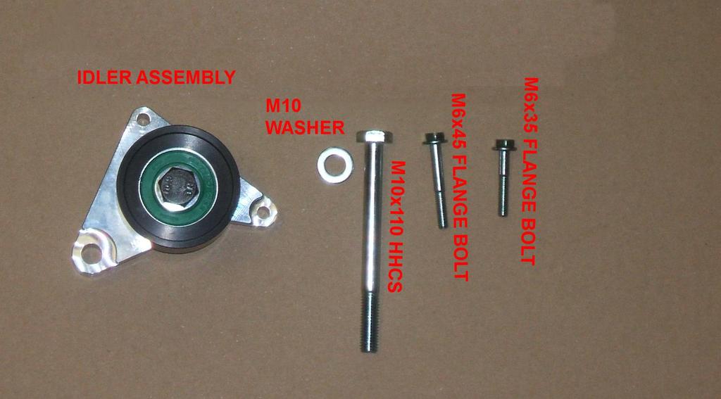
13 7. Using a pair of pliers, bend the lower water line back until it is clear of the belt line. You will need to cut the rubber line a little shorter. Note: Not all vehicles have this tube. 8. Using a 3/8 drive ratchet, release the tension from the drive belt and insert an Allen wrench or bolt into the locking holes to lock it in place. Remove the belt. 9. Remove the 7 rib idler in photo 25. Keep it as it will be installed onto the supercharger assembly later. 10. Unclip the wires that are attached to the dipstick tube. Unbolt the dipstick tube and pull out the dipstick tube. Push the wires back and reinstall the tube with the wires behind it. Page 13 of 38


14 INJECTOR REPLACEMENT 1. Remove the 4 bolts on the fuel feed tube as well as the 1 holding it to the timing case. Pull the tube out. 2. Remove the 4 bolts holding the fuel rails to the lower intake manifold. Unplug the connector on the rear of the drivers side fuel rail and lift the rails out. 3. Unplug the fuel injectors, remove the retainers and pull out the injectors. 4. Using the grease supplied with the injectors, grease the o-rings and install the new injectors in place of the stock ones and plug them in. You will not be reusing the retainer clips. 5. Reinstall the injector rails and reconnect the plug on the back. Install the 2 bolts on the passenger side but do not install the drivers side bolts until after the manifold is installed. 6. On the fuel feed tube, you will drill a new mounting hole as in photo 29. The hole will be centered on the bracket and 1.25" from the end. Lightly grease the o- rings and reinstall the tube and bolts. Gently bend the fuel tube until you can reinstall the mounting bolt through the new hole. Page 14 of 38


15 PLENUM INSTALLATION 1. Transfer the large gasket from the lower flange on the stock plenum to the grove in the new plenum. 2. Transfer the MAP sensor from the top of the stock plenum to the back of the new plenum. Transfer the purge valve to the new manifold. 3. Install 3 of the supplied flange bolts into the passenger side of the lower intake manifold. These bolts will need to stay above the mounting surface by about 1/2". This will allow you to install the new plenum by slipping it under the bolts and over the top of the drivers side fuel rail. 4. Unclip the wire harness on both valve cover. Using a pair of side cutters, cut off the 4 tabs that held the wire harness. Page 15 of 38


 You will need to gently bend the fuel line in order to clear the connector.")

16 5. After you have slipped the manifold under the 3 bolts, start the rest of the bolts around the manifold but DO NOT TIGHTEN THEM YET. Using the supplied 12mm long wrench, snug down the 3 bolts under the manifold. You will have to put a small bend in the end of the wrench to reach over the fuel rails. Photo35 6. Tighten down the rest of the bolts to ft-lbs then tighten the 3 bolts under the plenum to approx. the same torque. 7. Reinstall the 2 bolts on the drivers side fuel rail. Plug in the MAP sensor and purge valve. You will have to remove some tape from the harness and pull out some extra wire. 8. Install the supplied, square cut o-rings into the grooves in the throttle body mounting faces. Transfer the throttle bodies from the stock plenum to the new plenum reusing the stock mounting bolts. You will need to twist the 90º fitting down using a pair of pliers in order to attach the water lines. (photo 37) You will need to gently bend the fuel line in order to clear the connector. Plug in the connector for the rear throttle body. 9. You will now install the throttle body extension harness. It measures approximately 17 in length. Connect to the engine harness on the driver s side and route along the front of the engine to the relocated throttle body. Ensure the connectors are fully engaged and locked together. Secure to the wire loom located at the front of the engine 10. Attach the stock water line from the back of the engine to the straight tube on the rear throttle body. Using a new section of 3/8 hose, connect the 90º 11. fitting on the rear throttle body to the 90º fitting on the front throttle body. Then run a long piece of 3/8 line from the straight fitting on the front throttle body, around the back of the engine to the supply line mounting point on the drivers Page 16 of 38

 IDLER MOUNTING 1.")


17 side. Secure all lines with hose clamps. 12. You will be running the supplied ½ hose from the driver side hard pipe to the lower fitting on the overflow tank you will be installing later. You will need to route this hose beneath the Supercharger (Photo 38a) IDLER MOUNTING 1. Remove the 3 bolts in photo. They will not be reused. 2. Install the Idler assembly using the supplied bolts. The long 6mm bolt will go in the hole under the coolant inlet neck. Make sure the idler plate is sitting flat before tightening bolts. 3. Tighten the center bolt holding on the idler. 4. Using a pair of pliers, bend the upper harness clip mounting tab, on the dipstick tube, back to clear the belt. Page 17 of 38


18 SUPERCHARGER MOUNTING 1. Remove the 2 air ducts by squeezing the 2 plastic clips and push the ducts back. It may take some finagling to get the ducts out of the car. These will not be reused. 2. Start by rounding out and enlarging the air box inlet hole on the drivers side. 3. Remove the 5 bolts on the timing cover and the 2 bolts holding the grounding wires on the top of the timing cover. 4. Remove the relay box and hang it up out of the way. Unbolt the bracket. 5. You will need to elongate the holes by about 1/4" in the direction of the arrows. This will allow you to slide the relay box over slightly when reinstalled to provide some more clearance for the blower when it is reinstalled. Do not reinstall the bracket yet. Page 18 of 38


 Don't forget the ground wires on the top 2 bolts.")
19 6. Install the inlet boot into the hole from the engine compartment. Just leave it loose in there for now. (photo 45) 7. Lower the blower assembly into the car. Make sure you are clear of all the lines and hoses. Using a screwdriver, mount the inlet tube onto the inlet of the blower. You will have to adjust the inlet tube to allow the blower plate to meet up with the timing cover and keep the inlet boot from kinking. Route the drain line on the bottom of the blower down to the lower pan so it is easy to access for changing the oil. 8. Using the supplied bolts, mount the blower plate to the timing cover. You will have to remove the lower idler to insert the mounting bolts. Make sure you are not pinching any of the wire harness and make sure it sits flush and tighten the bolts. 9. Install the upper support plate by mounting it to the supercharger plate and to the top of the timing case. (photo 46) Don't forget the ground wires on the top 2 bolts. Tighten the belt on the back of the supercharger. 10. Install the #56 hose clamp to hold the inlet boot to the supercharger. 11. Install the 7 rib idler removed earlier onto the blower plate using the supplied spacer and hardware. Reinstall the lower idler. (photo 46) 12. Reinstall the relay box with the modified bracket and slide it away from the supercharger. (photo 47) 13. You can now install the new belt per the Page 19 of 38
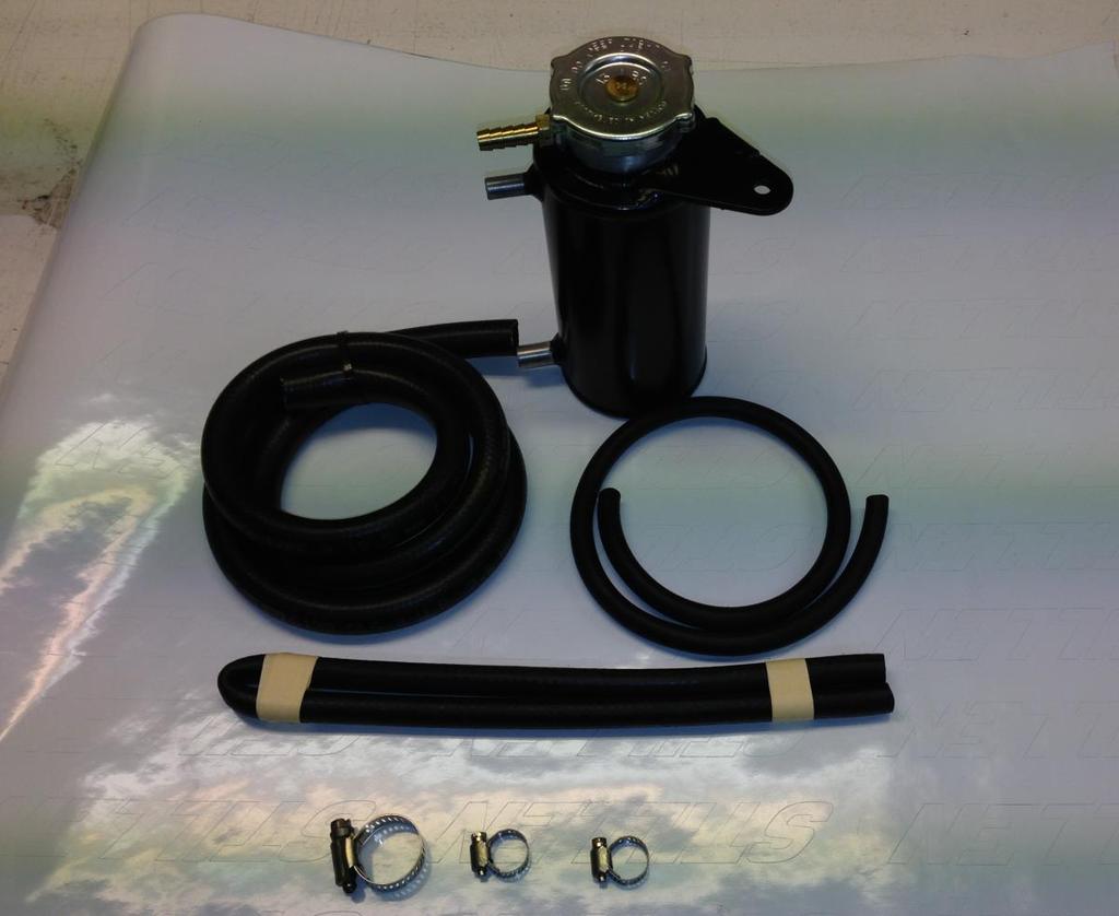
 to make sure it is clear of the belt. OVERFLOW BOTTLE MOUNTING. 1. Mount the bracket to the air box bracket on the passenger side reusing the stock bolt.")


20 new routing diagram. Release the tensioned and remove the Allen wrench or bolt you had holding the tensioned locked. 14. Check the tube you bent earlier (pg. 12 step 7) to make sure it is clear of the belt. OVERFLOW BOTTLE MOUNTING. 1. Mount the bracket to the air box bracket on the passenger side reusing the stock bolt. 2. Using a pair of pliers, gently bend the overflow nipple down and pointed in the same general direction of the upper radiator hose. 3. Install the supplied piece of hose from the overflow nipple on the head to the middle nipple on the overflow bottle. You will need to run the ½ hose along the core support from the driver side hard pipe you started earlier to the lower nipple on the overflow bottle. Run a hose from the top nipple down below for excess drainage. You can reuse the stock hose clamps. Page 20 of 38


21 INTERCOOLER INSTALLATION 1. First you will be mounting the pump. The pump is mounted to the bracket using 2 Adel clamps. In front of the drivers wheel well there is an open area. Remove the lower air box baffle and bracket. You may have to temporarily remove the horn to have more room to work. 2. Hold the pump bracket up to the sheet metal and mark the mounting holes. Using a drill, drill 2 pilot holes. Hold the pump bracket up and install using the supplied self-drilling screws. Reinstall the horn if removed. 3. Next is the tank. Install one of the 5/8" to 3/4" dual ID hoses to the fitting on the bottom of the tank and secure it with a hose clamp. Feed the 3/4" end under the blower to the top of the pump and secure that end with a clamp. Mount the tank to the 2 holes in the sheet metal surrounding the master cylinder compartment. 4. Install the second dual-id hose with the 3/4" end onto the outlet side of the pump and secure with a clamp. Route this line around the core support and in front of the radiator. Leave it there for now. 5. Using one of the 5/8" hoses with the 90º ends, attach the 90º end to the end of the intercooler tank and attach the other end to the intercooler that is mounted inside the plenum. You will have to route it and cut it to length and secure it with clamps. 6. Install one of the other 90º hoses to the other side of the intercooler and secure with a clamp. Route it down under the new radiator overflow tank, through the air box inlet hole, and out in front of the radiator. Leave it there for now. Page 21 of 38

22 7. Mount the heat exchanger to the passengers side in front of the radiator. Use the self drilling screws to mount it. 8. Attach the hoses to the heat exchanger and secure with hose clamps. your routing should be like the diagram. Page 22 of 38


23 9. Mount the relay inside the master cylinder compartment. Wire the relay per the wire diagram. Route the main power supply wire and the switched wire under the cowl and to the battery compartment. 10. Remove the passengers side of the cowl, unclip the fuse box, and lift it out. Remove the cover. 11. You will attach the switched power wire to the wire in photo. 12. Reassemble the fuse box, reinstall it and reinstall the cowl. Page 23 of 38


24 BYPASS VALVE / VACUUM LINES 1. Cut approx. 2 1/2" off of the straight end of the 1" hose. You will be using both pieces. NOTE: This is already assembled for you. 2. Assemble the bypass valve and hose parts per picture and secure with hose clamps. 3. Attach the 90º end to the inlet boot and secure with a clamp. Route the supplied vacuum line from the bottom of the bypass valve through the opening in the timing case, to the vacuum fitting on the front runner. (See vacuum diagram on the next page) Leave the valve hanging there for now. 4. Using 2 5/8" hoses with the 90º ends, the 5/8" T fitting, and hose clamps, route the crankcase vent line from the passenger side, around the back of the engine, to the T fitting. Use a small cut off piece from the T to the drivers side valve cover and use the other 90º hose from the T fitting, under the blower to the fitting on the inlet boot. You will have to trim the hoses to the proper length. 5. Using pieces of the 3/8" Page 24 of 38

25 hose and clamps, route these lines from the PCV valves to the 90º fittings in the back of the manifold. (photo 60) 6. Using the 3/8" coupler, and provided 3/8 hose, extend and connect the brake booster line to the 90 elbow on the back of the manifold. You will be connecting the purge valve to the straight fitting in between the throttle bodies using the ¼ id hose. Page 25 of 38


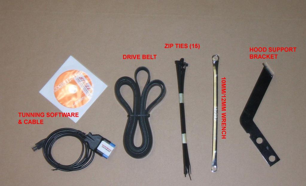
26 INLET INSTALLATION 1. Remove the hood latch support and replace with the supplied one. You will need to drill out the rivet in. You will need to move it around in order to line up the hole on the hood latch. (Photo 61) 2. Install the filters onto the Y with the angles as in photo Transfer the MAF sensors from the stock intakes into the new Y. Check to make sure the seals that are on the base of the MAFs stay in place. 4. Install the step boot onto the Y. Insert the short end of the elbow into the boot and secure with clamps. Do not tighten the clamps very tight yet, as you will need to move the parts around to get them in place. 5. Slip a #40 clamp through the hole that was widened at the beginning of the install, and over the inlet boot. You will want the screw on the clamp pointing up on the drivers side so you can reach it through the holes in the core support. (photo 64) Page 26 of 38


.")
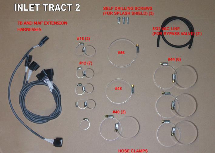
27 6. Slide the loosely assembled Y into the inlet boot. 7. Adjust the Y until it is behind the bumper and tighten all the clamps. IMPORTANT: When attaching the reducer, make sure the Y and elbow are not inserted too far. If the tubes are inserted past the flat sections on the reducer, the step may create turbulence. (photo 65) Make sure the Y is in a straight line with the elbow. 8. Install the MAF extension harnesses. They are approximately 43 in length. Beginning on the driver s side, connect to the factory MAF connection, ensuring the connector is fully seated and locked into position. Route through the radiator support (it is recommended to follow the intercooler hose routing). Secure the harness so that it will not contact any sharp metal edges, the heat exchanger or radiator. Repeat procedure for passenger side MAF.. 9. Plug in the MAF sensors. 10. Install the splash shield using the 3 self drilling screws. NOTE: The air deflector/splash shield is designed to prevent inconsistent MAF readings and A/F ratios. It MUST be installed or drivability issues will result. Page 27 of 38


28 CHARGE PIPE INSTALLATION 1. Slide the 2 short boots onto the throttle body ends of the tube, the longer one onto the supercharger end, and slide them down 2. Attach the bypass valve to the fitting on the bottom of the inlet pipe and secure with a clamp. 3. Install the pipe and slide the 3 boots onto the throttle bodies and blower. Secure with the clamps. 4. Reinstall your strut tower bar placing the provided spacers under the ends of the bar. ECU REFLASH Follow the instructions provided with the ECU tuning cable and software. Page 28 of 38
29 FINAL CHECK 1. Attached to the supercharger is an instruction tag and brass vent fitting. Follow these instructions for installing this vent plug in place of the shipping plug on the blower. 2. Check the oil level of the supercharger. It is shipped pre-oiled, however it is best to check the level before running. 3. Check for any unplugged vacuum lines or connectors. 4. Look around the belts to check for any wires or vacuum lines that may touch the belts. Secure everything clear of the belts and pulleys using zip ties. If zip tying vacuum lines, be sure not to pull the ties too tight and pinch off the lines. 5. Top off any coolant lost from the cooling system and fill the radiator overflow tank to the fill line. 6. Fill the intercooler system. NOTE: If you live in a climate that sees freezing temperatures, you should fill the system with a 50/50 antifreeze/water mixture for winter. If you do not have freezing temperatures or for summer use, mix 1 cup Water Wetter with water in the system. 7. Reconnect the battery. Turn on the ignition, but do not start the car. The intercooler pump should start up. Fill the system as the air bleeds out. Do not let the pump suck in air as it may create an airlock. If this happens, disconnect the water line from the end of the tank, hold a finger over the fitting, and blow into the tank. This will force the water down into the pump and will release the airlock. The water level in the tank should be up to the base of the filler neck. Check the system for leaks. 8. Reinstall the fascia, battery and brake master cylinder cover. EXTREMELY IMPORTANT: To insure maximum performance and safety, boost pressure MUST be checked immediately after install. We recommend using a quality (Snap-0n,AEM, HKS etc) calibrated boost/pressure gauge that reads 10-15psi (1 BAR) maximum if analog or a digital gauge. The gauge must be T eed into the small front vacuum line that leads to the supercharger bypass valve. Maximum boost reading will be obtained at WOT in 3 rd 7000 rpm. We suggest you avoid hitting the RPM limiter or an incorrect reading will result. A dynamometer can be used if traffic conditions or an off road location is not available for proper testing. The boost reading should be from psi. Pressure can vary due to atmospheric conditions and dyno types. For example a Dynojet dyno boost reading will be.3-.4 low as compared to actual road testing. Make sure to do 2-3 tests and write down your results to confirm an accurate reading. If outside the recommended pressure readings please contact Stillen technical support immediately for further assistance Notice to Installer: It is important to give the section of these instructions titled Care and Maintenance to the owner of the vehicle. Page 29 of 38
30 CARE & MAINTENANCE The STILLEN supercharger is designed to provide power AND reliability. All bearings used are lubricated and sealed. However there are some basic care items that should be checked regularly. Always use the best fuel available for your vehicle. MINIMUM OF 91 OCTANE. Check the oil in your supercharger every 2,500 miles. The initial fluid change should be done 2,500 miles after install and then every 7,500 miles IF FOR WHATEVER REASON THE VEHICLE STARTS TO PING OR DETONATE UNDER LOAD OR HIGH RPM GET OFF THE THROTTLE! Changing climate, altitude or atmospheric conditions will affect your vehicle. Various types of fuel (e.g. oxygenated, ethanol, etc) will also affect the performance of your vehicle. Check the supercharger drive belts regularly. Replace any that show signs of cracking/tearing. Check coolant level in intercooler often. It should be changed annually to maintain peak performance. Remember to use antifreeze if you live in an area that sees freezing conditions. Check your air filter regularly. A clogged air filter can drastically affect your vehicle. Clean and oil your air filter when it becomes dirty. DO NOT OVER OIL. High quality synthetic oil is recommended and oil changes should be done every 3,000 miles. This improves engine durability and longevity in a forced induction application. Do not alter, modify or adjust the Stillen supercharger system in any way. Unauthorized changes to boost levels, electronics, tuning or any other system will void warranties and can cause catastrophic engine damage. Page 30 of 38

31 Page 31 of 38

32 Page 32 of 38

33 Page 33 of 38

34 Page 34 of 38

35 Page 35 of 38

36 Page 36 of 38
 The taller one will go on the rear fuel rail bolt and the shorter one will be installed on the front 2 bolts")

37 Engine Cover Supplement Instructions 1. You will be installing the engine cover brackets where shown in (Fig.1) The taller one will go on the rear fuel rail bolt and the shorter one will be installed on the front 2 bolts which are holding on the support brace. See (Fig.2) You will be reusing the existing bolts already in place. For the front bracket it is recommended to loosen the bolts which secure the grounds onto the drive plate support. Page 37 of 38

38 2. Once installed you will install the engine cover using the supplied BHCS bolts and nuts. See (Fig.3) Page 38 of 38
NISSAN 350Z 300HP ENGINE INTERCOOLED SUPERCHARGER INSTALLATION INSTRUCTIONS
 NISSAN 350Z 300HP ENGINE INTERCOOLED SUPERCHARGER INSTALLATION INSTRUCTIONS 2005 STEVE MILLEN SPORTPARTS, INC. All rights reserved. No part of this publication may be reproduced, transcribed, transmitted,
INSTALLATION INSTRUCTIONS STILLEN SUPERCHARGER KIT Nissan 350Z P/N &
 Equipment needed: 1. Assorted sockets and wrenches 2. +,- Screwdrivers 3. Assorted pliers/ Clamps 4. Wire cutting/crimping tools 5. Thread locking compound (blue) 6. Solder gun/ shrink wrap (optional)
Procharger Stage II Intercooled Supercharger System (11-14 GT)
") Procharger Stage II Intercooled Supercharger System (11-14 GT) Installation Time: Approximately one day. Installed on 2012 Mustang GT 5.0/Manual Required Tools 3/8 Socket Set (Standard and Metric) 1/2
Procharger Stage II Intercooled Supercharger System (11-14 GT) Installation Time: Approximately one day. Installed on 2012 Mustang GT 5.0/Manual Required Tools 3/8 Socket Set (Standard and Metric) 1/2
WARNING: IF YOU ARE NOT EXPERIENCED IN THE AREA OF AUTOMOTIVE MECHANICS WE STRONGLY URGE THAT YOU REFER THIS INSTALLATION TO YOUR MECHANIC.
 INSTALLATION INSTRUCTIONS STILLEN SUPERCHARGER KIT 2003+ Infiniti G35 Materials supplied: See attached list Equipment needed: 1. Assorted sockets and wrenches 2. +,- Screwdrivers 3. Assorted pliers/ Clamps
INFINITI G35 298HP ENGINE INTERCOOLED SUPERCHARGER INSTALLATION INSTRUCTIONS
 INFINITI G35 298HP ENGINE INTERCOOLED SUPERCHARGER INSTALLATION INSTRUCTIONS 2005 STEVE MILLEN SPORTPARTS, INC. All rights reserved. No part of this publication may be reproduced, transcribed, transmitted,
TITAN SUPERCHARGER INSTALLATION INSTRUCTIONS
 2007-2012 TITAN SUPERCHARGER INSTALLATION INSTRUCTIONS Rev. 01-07-2013 2013 STEVE MILLEN SPORTPARTS, INC. All rights reserved. No part of this publication may be reproduced, transcribed, transmitted, or
4. Remove (4) 10mm and (1) 7mm bolt that holds fascia at front corners, on each side
 10mm and (1) 7mm bolt that holds fascia at front corners, on each side") 2010 Camaro LS3 1. Disconnect battery ground 2. Remove front wheels 3. Remove (5) push pins and (5) #20 torx screws on inner front wheel well liners and remove liners on each side 4. Remove (4) 10mm and
2010 Camaro LS3 1. Disconnect battery ground 2. Remove front wheels 3. Remove (5) push pins and (5) #20 torx screws on inner front wheel well liners and remove liners on each side 4. Remove (4) 10mm and
IAG Street Series Air / Oil Separator (AOS) For 2017 WRX
 For 2017 WRX") P IAG Street Series Air / Oil Separator (AOS) For 2017 WRX Part# IAG-ENG-7152 Tools Required: Ratchet, torque wrench, extensions, needle nose pliers, hose cutter, snips/scissors, flathead screwdriver,
P IAG Street Series Air / Oil Separator (AOS) For 2017 WRX Part# IAG-ENG-7152 Tools Required: Ratchet, torque wrench, extensions, needle nose pliers, hose cutter, snips/scissors, flathead screwdriver,
SLP Camaro ZL1 STAGE 3 (650 HP)
") SLP - 2012 Camaro ZL1 STAGE 3 (650 HP) PART #26002 PACKING LIST Before installation, use this check list to make sure all necessary parts have been included. ITEM QTY CHECK PART NUMBER DESCRIPTION 1. 1
SLP - 2012 Camaro ZL1 STAGE 3 (650 HP) PART #26002 PACKING LIST Before installation, use this check list to make sure all necessary parts have been included. ITEM QTY CHECK PART NUMBER DESCRIPTION 1. 1
Installation manual BMW E TS1/TS2
 Installation manual BMW E46 330 TS1/TS2 Technical support Europe: +4741558555 Technical support USA: (858)314-2954 Email support: support@esstuning Installation manual BMW E46 330 TS1/TS2 Remove and send
05-08 GT. Hellion Power Systems Mustang Kit Instructions
 Hellion Power Systems 05-08 Mustang Kit Instructions 1. Disconnect Battery 2. Drain Radiator, keep fluid for re-installation. 3. Remove air box and inlethoses. 6. Next, underneath, punch oil pan for turbo
IAG Street Series Air / Oil Separator (AOS) For WRX
 For WRX") P IAG Street Series Air / Oil Separator (AOS) For 2015-16 WRX Part# IAG-ENG-7152 Tools Required: Ratchet, torque wrench, extensions, needle nose pliers, hose cutter, snips/scissors, flat head screw driver,
P IAG Street Series Air / Oil Separator (AOS) For 2015-16 WRX Part# IAG-ENG-7152 Tools Required: Ratchet, torque wrench, extensions, needle nose pliers, hose cutter, snips/scissors, flat head screw driver,
2015+ SUBARU STI FRONT-MOUNT INTERCOOLER PARTS LIST AND INSTALLATION GUIDE INSTALL DIFFICULTY DISCLAIMER CAUTION INSTALL PROCEDURE TOOLS NEEDED
 PARTS LIST AND PARTS INCLUDED 1PC ALUMINUM INTAKE PIPE 1PC BAR-AND-PLATE INTERCOOLER 1PC STEEL CRASH BAR W/ MOUNTING HARDWARE 2PC HOT-SIDE INTERCOOLER PIPES 2PC COLD-SIDE INTERCOOLER PIPES 1PC BPV FLANGE
IAG Competition Series Air / Oil Separator (AOS) For WRX
 For WRX") P IAG Competition Series Air / Oil Separator (AOS) For 2015-16 WRX Part# IAG-ENG-7252 Tools Required: Ratchet, torque wrench, extensions, needle nose pliers, hose cutter, snips/scissors, flat head screw
P IAG Competition Series Air / Oil Separator (AOS) For 2015-16 WRX Part# IAG-ENG-7252 Tools Required: Ratchet, torque wrench, extensions, needle nose pliers, hose cutter, snips/scissors, flat head screw
BBK Intake Manifold Kit ( L) - Installation Instructions
 - Installation Instructions") BBK Intake Manifold Kit (86-93 5.0L) - Installation Instructions The below installation instructions work for the following products: BBK Intake Manifold Kit (86-93 5.0L) Please read through the instructions
BBK Intake Manifold Kit (86-93 5.0L) - Installation Instructions The below installation instructions work for the following products: BBK Intake Manifold Kit (86-93 5.0L) Please read through the instructions
8 Zip Tie Zip Tie 1 Union Fitting 1 ½ ½ Union Reducer Fitting Union 1 5/8 ½ (For Plastic Intake Manifold Vehicles)
") P IAG Street Series Air / Oil Separator (AOS) For 2017 STI Part# IAG-ENG-7151 Tools Required: Ratchet, torque wrench, extensions, needle nose pliers, hose cutter, snips/scissors, flat head screw driver,
P IAG Street Series Air / Oil Separator (AOS) For 2017 STI Part# IAG-ENG-7151 Tools Required: Ratchet, torque wrench, extensions, needle nose pliers, hose cutter, snips/scissors, flat head screw driver,
Always wear safety glasses when working on your vehicle.
 90-93 MAZDA MIATA SUPERCHARGER KIT The KraftWerks 90-93 Mazda Miata Supercharger Kit was designed for easy installation. Competent mechanics with the appropriate tools will find the process to be relatively
IAG Competition Series Air / Oil Separator (AOS) For 2017 STI
 For 2017 STI") P IAG Competition Series Air / Oil Separator (AOS) For 2017 STI Part# IAG-ENG-7251 Tools Required: Ratchet, torque wrench, extensions, needle nose pliers, hose cutter, snips/scissors, flat head screw driver,
P IAG Competition Series Air / Oil Separator (AOS) For 2017 STI Part# IAG-ENG-7251 Tools Required: Ratchet, torque wrench, extensions, needle nose pliers, hose cutter, snips/scissors, flat head screw driver,
IAG Street Series Air / Oil Separator (AOS) For WRX & WRX STI
 For WRX & WRX STI") IAG Street Series Air / Oil Separator (AOS) For 2006-07 WRX & 2004-07 WRX STI Part# IAG-ENG-7100 Tools Required: Ratchet, torque wrench, extensions, needle nose pliers, hose cutter, snips/scissors, flat
IAG Street Series Air / Oil Separator (AOS) For 2006-07 WRX & 2004-07 WRX STI Part# IAG-ENG-7100 Tools Required: Ratchet, torque wrench, extensions, needle nose pliers, hose cutter, snips/scissors, flat
99-04 GT. Hellion Power Systems Mustang GT Kit Instructions
 Hellion Power Systems 99-04 Mustang GT Kit Instructions Part 1 Hellion recommends that the front suspension system be installed either by trained professionals or by 5.Remove rack bolts K-Member Installation
2006 Honda Civic SI Supercharger Kit Installation Instruction Kit #
 2006 Honda Civic SI Supercharger Kit Installation Instruction Kit #350-091 3239 MONIER CIRCLE, STE.5 RANCHO CORDOVA, CA 95742 916.635.4550 FAX 916.635.4632 www.ct-engineering.com INS-157 VERSION: 3.25.2009
INSTALLATION INSTRUCTIONS
 HIGH FLOW AIRFLOW METER INSTALLATION INSTRUCTIONS PART NUMBER D763-1600A APPLICATION: 2001-06 E46 M3 Parts List: Hose clamp 64Z (7) Plastic Rivets Air Filter Temp Sensor & Harness (2) Button Head Screws
Subaru Front Mount Intercooler Kit STI Subaru Front Mount Intercooler Kit STI
 Subaru Front Mount Intercooler Kit STI 2008-2014 715500 Subaru Front Mount Intercooler Kit STI 2008-2014 Congratulations on your purchase of the Subaru Front Mount Intercooler Kit STI 2008-2014. The following
L Intake Manifold Part #
 86-93 5.0L Intake Manifold Part #5001-5002 I N S T A L L A T I O N I N S T R U C T I O N S Supplied Materials Bottom cover, Upper manifold, Lower manifold, Plenum cover plate, 1501 Throttle body (comes
INSTALLATION INSTRUCTIONS AIR/OIL SEPARATOR KIT
 INSTALLATION INSTRUCTIONS AIR/OIL SEPARATOR KIT 2015+ SUBARU WRX (LHD ONLY) Document: 19-0136 Support: info@radiumauto.com This document covers the installation of the Radium brake master cylinder brace
03-04 Mach 1. Hellion Power Systems Mach 1 Kit Instructions
 Hellion Power Systems 03-04 Mach 1 Kit Instructions Part 1 Hellion recommends that the front suspension system be installed either by trained professionals or by 5.Remove rack bolts K-Member Installation
2015 Corvette Supercharger System Instructions
 2015 Corvette Supercharger System Instructions These instructions are meant to serve as a guide to the installation of the ECS 2015 Corvette Supercharging system. Please be sure to use all safety equipment
Wrenches: ⅞, 8mm, 10mm, 13mm, 19mm P. allen, Other: Electrical Tape
 IAG Street Series Air / Oil Separator (AOS) For 2008-14 STI Part# IAG-ENG-7100 Tools Required: Ratchet, torque wrench, extensions, needle nose pliers, hose cutter, snips/scissors, flat head screw driver,
IAG Air / Oil Separator (AOS) For STi
 For STi") IAG Air / Oil Separator (AOS) For 2008-14 STi Part# IAG-ENG-7000 Tools Required: Ratchet, torque wrench, extensions, needle nose pliers, hose cutter, snips/scissors Sockets: 10mm, 12mm 13mm Wrenches: 10mm,
IAG Air / Oil Separator (AOS) For 2008-14 STi Part# IAG-ENG-7000 Tools Required: Ratchet, torque wrench, extensions, needle nose pliers, hose cutter, snips/scissors Sockets: 10mm, 12mm 13mm Wrenches: 10mm,
Huron Speed Products Twin Turbo Install Gen 2 CTS-V (09-15)
") Huron Speed Products Twin Turbo Install Gen 2 CTS-V (09-15) The following install guide is simply that, a guide to help you with installation. It is by no means the exact method to perform installation,
Huron Speed Products Twin Turbo Install Gen 2 CTS-V (09-15) The following install guide is simply that, a guide to help you with installation. It is by no means the exact method to perform installation,
MAZDASPEED3 Intercooler Instructions
 MAZDASPEED3 Intercooler Instructions Congratulations on your purchase of the COBB Tuning Front Mount Intercooler System for your 2007-2009 Mazdaspeed3. The following instructions should assist you through
SL63 Weistec M156 Supercharger System Installation Guide Stage 1 / Stage 2
 SL63 Weistec M156 Supercharger System Installation Guide Stage 1 / Stage 2 WARNING! DO NOT HAVE YOUR ECU REPROGRAMMED ANYWHERE BUT AT WEISTEC FOR THIS SUPERCHARGER. THE AMG 63 USES AN ELECTRONIC THROTTLE
Edelbrock 5.0L Mustang GT Supercharger Part #1588 & 1589
 Edelbrock 5.0L Mustang GT Supercharger Part #1588 & 1589 INTRODUCTION Edelbrock 5.0L Ford Supercharger System Thank you for purchasing the Edelbrock 5.0L Ford Supercharger System for the Mustang GT. The
Slingshot Rotrex Supercharger Kit
 Slingshot Rotrex Supercharger Kit This supercharger kit improves on the Slingshot by forcing more dense air into the engine and creating more power. Installation time of the supercharger depends on you
IAG Street Series Air / Oil Separator (AOS) For WRX & WRX STI
 For WRX & WRX STI") IAG Street Series Air / Oil Separator (AOS) For 2006-07 WRX & 2004-07 WRX STI Part# IAG-ENG-7150 Tools Required: Ratchet, torque wrench, extensions, needle nose pliers, hose cutter, snips/scissors, flat
IAG Street Series Air / Oil Separator (AOS) For 2006-07 WRX & 2004-07 WRX STI Part# IAG-ENG-7150 Tools Required: Ratchet, torque wrench, extensions, needle nose pliers, hose cutter, snips/scissors, flat
Instant Chat off the main page of Or simply call our tech team at
 FRONT MOUNT INTERCOOLER 2008-13 STI 2014-04- 08 Thank you for purchasing this PERRIN product for your car! Installation of this product should only be performed by persons experienced with installation
IAG Street Series Air / Oil Separator (AOS) For WRX & WRX STI
 For WRX & WRX STI") IAG Street Series Air / Oil Separator (AOS) For 2006-07 WRX & 2004-07 WRX STI Part# IAG-ENG-7150 Tools Required: Ratchet, torque wrench, extensions, needle nose pliers, hose cutter, snips/scissors, flat
IAG Street Series Air / Oil Separator (AOS) For 2006-07 WRX & 2004-07 WRX STI Part# IAG-ENG-7150 Tools Required: Ratchet, torque wrench, extensions, needle nose pliers, hose cutter, snips/scissors, flat
#TL T EA888 GEN 3 FUELING SYSTEM/ INSTALLATION INSTRUCTIONS
 #TL100069 2.0T EA888 GEN 3 FUELING SYSTEM/ INSTALLATION INSTRUCTIONS Notes: These instructions were written for a North American specification MkVII GTI. Other models, like the Golf R, are similar. When
Huron Speed Products Twin Turbo Install Gen 2 CTS-V (09-15)
") Huron Speed Products Twin Turbo Install Gen 2 CTS-V (09-15) 1 2 Remove two bolts in trunk cover with 8mm socket. Pull up on cover to remove. Unscrew net tie down on side cover where battery is located
Huron Speed Products Twin Turbo Install Gen 2 CTS-V (09-15) 1 2 Remove two bolts in trunk cover with 8mm socket. Pull up on cover to remove. Unscrew net tie down on side cover where battery is located
Weistec M113K Supercharger System Installation Guide
 Weistec M113K Supercharger System Installation Guide WARNING! DO NOT HAVE YOUR ECU REPROGRAMMED ANYWHERE BUT AT WEISTEC FOR THIS SUPERCHARGER. THE AMG 55 USES AN ELECTRONIC THROTTLE CONTROL (ETC), WHICH
2017+ L5P Duramax 3 ½ Down Pipe & EGR Fix Kit
 2017+ L5P Duramax 3 ½ Down Pipe & EGR Fix Kit Covers installation of PN s: WCF100630, WCF100829 Note: This Kit is for off road competition use only! Off Road Competition Use Tuning & Exhaust System is
INSTALLATION INSTRUCTIONS CATCH CAN KIT
 INSTALLATION INSTRUCTIONS CATCH CAN KIT FORD FOCUS Document: 19-0150 Support: info@radiumauto.com STEPS 1-19 COVER THE PCV SIDE CATCH CAN KIT (P/N: 20-0315) STEPS 20-32 COVER THE CRANKCASE CATCH CAN KIT
3.4L V6 SUPERCHARGER 7 TH INJECTOR KIT
 Part Number: 00602-17620-260 00602-17620-261 00602-17620-263 00602-17620-264 00602-17620-274 00602-17620-275 00602-17620-276 Section I Installation Preparation Kit Contents Item # Quantity Reqd. Description
CHALLENGER TWIN TURBO SYSTEM INSTALLATION INSTRUCTIONS
 CHALLENGER TWIN TURBO SYSTEM INSTALLATION INSTRUCTIONS 1 Verify contents of kits with supplied packing list 1) Unhook the battery. 2) Remove wheel wells & front fascia of vehicle. 3) Remove the catalytic
CLS63 Weistec M156 Supercharger System Installation Guide Stage 1 / Stage 2
 CLS63 Weistec M156 Supercharger System Installation Guide Stage 1 / Stage 2 WARNING! DO NOT HAVE YOUR ECU REPROGRAMMED ANYWHERE BUT AT WEISTEC FOR THIS SUPERCHARGER. THE AMG 63 USES AN ELECTRONIC THROTTLE
Deuce/Ace Installation Instructions
 HARDWARE KIT: Upper Mounting Plate: 2-7/16" (11mm) X 3.5" bolts 2-7/16" flange nuts 2-2" spacers 2-7/16" trim cap mounting washers 2 - plastic trim caps TOOLS NEEDED: safety glasses wrenches 16mm or 5/8"
03-04 Cobra. Hellion Power Systems Mustang Cobra Kit Instructions
 Hellion Power Systems 03-04 Mustang Cobra Kit Instructions NECESSARY PARTS REQUIRED FOR INSTALLATION Necessary: 03-04 Cobra hellion Kit ONLY 99-01 Alternator #YR3210346AA Alternator Bracket #XR3Z-10153-AB
ENGINE DEVELOPMENT INC.
 2003 Ford Expedition 4.6L& 5.4L We encourage you to read this manual thoroughly before you begin work, and perform the following: 1. A quick parts check to make certain your kit is complete. If you discover
IAG Street Series Air / Oil Separator (AOS) For WRX
 For WRX") IAG Street Series Air / Oil Separator (AOS) For 2008-14 WRX Part# IAG-ENG-7100 Tools Required: Ratchet, extensions, needle nose pliers, hose cutter, snips/scissors, flat head screw driver, hose clamping
IAG Street Series Air / Oil Separator (AOS) For 2008-14 WRX Part# IAG-ENG-7100 Tools Required: Ratchet, extensions, needle nose pliers, hose cutter, snips/scissors, flat head screw driver, hose clamping
97-02 JEEP TJ BODY LIFT KIT INSTRUCTIONS
 92RC60500 97-02 JEEP TJ BODY LIFT KIT INSTRUCTIONS Congratulations on your purchase of a new Rough Country 2 /3 Body Lift. We are committed to providing you with the best product available for the best
Instant Chat off the main page of Or simply call our tech team at
 FRONT MOUNT INTERCOOLER 2015+ WRX 2017-07-07 Thank you for purchasing this PERRIN product for your car! Installation of this product should only be performed by persons experienced with installation of
PRODUCT USE INFORMATION
 9RC61000 Jeep YJ Body Lift Thank you for choosing Rough Country for all your suspension needs. This body lift fits both manual and Automatic equipped vehicles!!! Refer to last page of this Instruction
Installation Instructions for: TOYOTA 3.4L SUPERCHARGER SYSTEM
 Installation Instructions for: TOYOTA 3.4L SUPERCHARGER SYSTEM 1996-2002 4Runner 1997-1998 T100 1997-2004 Tacoma 2000-2003 Tundra * PREMIUM FUEL REQUIRED * Magnuson Products LLC 1990 Knoll Drive, Bldg
Installation Instructions
 2011-2013 LML DURAMAX COMPOUND-ADD 2011-2015 LML A Duramax TURBO KIT Add INSTALL A Turbo INSTRUCTIONS Compound Kit Installation Instructions 1-800-955-0476 - www.industrialinjection.com - info@industrialinjection.com
96-04 tt. Hellion Power Systems Mustang Twin Turbo Kit Instructions
 96-04 tt Hellion Power Systems 1996-2004 Mustang Twin Turbo Kit Instructions 1. Disconnect battery and elevate front end of car on either Jack stands or a lift if available 2.Lock steering wheel and remove
Installation Instructions for: TOYOTA 4.5L SUPERCHARGER SYSTEM
 Installation Instructions for: TOYOTA 4.5L SUPERCHARGER SYSTEM 1995-1997 Land Cruiser * PREMIUM FUEL REQUIRED * Magnuson Products LLC 1990 Knoll Drive, Bldg A, Ventura, CA 93003 (805) 642-8833 phone *
INSTALLATION INSTRUCTIONS CATCH CAN KIT
 INSTALLATION INSTRUCTIONS CATCH CAN KIT FORD FOCUS Document: 19-0150 Support: info@radiumauto.com STEPS 1 TO 19 COVER THE PCV SIDE CATCH CAN KIT (P/N: 20-0315) STEPS 20-32 COVER THE CRANKCASE CATCH CAN
Performance Inlet Manifold
 Performance Inlet Manifold Tools needed (some tools not required on some models): 13mm Combination Wrench Flat Blade Screwdriver T30 Torx Driver T25 Torx Driver 10mm Combination Wrench and/or Socket with
INSTRUCTIONS E36 SUPERCHARGER WITH C38 BLOWER.
 INSTRUCTIONS 1996-1999 E36 SUPERCHARGER WITH C38 BLOWER. 1 Introduction Congratulations on your purchase of an Active Autowerke Supercharger, and welcome to the AA Tuning family. Your supercharger kit
These instructions were written for reference only and the use of a factory service manual is recommended.
 Introducing the CorkSport High Pressure Fuel Line designed for the MZR DISI. This fuel line is designed to replace the OEM fuel line which are prone to failure at the brazed connection at the rail. The
Special Note About The JDM High Performance Water Pump:
 Page 1 of 30 JDM Engineering, Inc. home Call Us! 732-780- 0770 back to Installation Instructions Electric Fan Upgrade Kit Electric Fan Wiring Diagram Thank you for your purchase of the JDM Engineering
Ford Racing Performance Improvement Intake Manifold (96-04 GT) Time Necessary: Approximately 4 hours
 Time Necessary: Approximately 4 hours") Ford Racing Performance Improvement Intake Manifold (96-04 GT) Time Necessary: Approximately 4 hours Tools Required: Ratchet and socket set Torque wrench Large adjustable wrench Needle nose pliers A dozen
Ford Racing Performance Improvement Intake Manifold (96-04 GT) Time Necessary: Approximately 4 hours Tools Required: Ratchet and socket set Torque wrench Large adjustable wrench Needle nose pliers A dozen
Edelbrock E-Force Supercharger Complete Competition Ford Mustang 5.0L Part # s: 15896
 Edelbrock E-Force Supercharger Complete Competition Part # s: 15896 Introduction Thank you for purchasing the Edelbrock Complete Competition Supercharger System for the 2011-2013 5.0L Ford Mustang GT.
FREE $15 Gift Card for every $100 spent on Ship To Home orders. Find Out How
 1 of 29 10/12/2011 5:05 PM FREE $15 Gift Card for every $100 spent on Ship To Home orders. Find Out How Ford Ranger/Explorer/Mountaineer 1991-1999 Intake Manifold REMOVAL & INSTALLATION Print The engines
SHELBY GT500
 2007-2009 SHELBY GT500 Removal of Factory Unit WARNING: 1. Radiator fluid must be handled properly. Please observe local ordinances with regards to handling and disposal. 2. Allow vehicle and components
Low Range HD 2 Inch Body Lift Kit (Sidekick, GV, Vitara, Tracker, X90) SKU# KSP-BL2
 SKU# KSP-BL2") Low Range HD 2 Inch Body Lift Kit (Sidekick, GV, Vitara, Tracker, X90) SKU# KSP-BL2 Installation Instructions Background: These instructions are designed for installing the 2 body lift. They can also be
Low Range HD 2 Inch Body Lift Kit (Sidekick, GV, Vitara, Tracker, X90) SKU# KSP-BL2 Installation Instructions Background: These instructions are designed for installing the 2 body lift. They can also be
WARNING: ALWAYS relieve fuel pressure before disconnecting any fuel related component. DO NOT allow fuel to contact engine or electrical components.
 4.0L V8 - VINS [K,U] Selected Block 1990 Lexus LS 400 For Lextreme Powertrain 2020 S. Hacienda Blvd. # D Hacienda Heights California 91745 Copyright 1998 Mitchell Repair Information Company, LLC Friday,
INSTALLATION INSTRUCTIONS PORT INJECTION KIT (PIK)
") INSTALLATION INSTRUCTIONS PORT INJECTION KIT (PIK) FORD FOCUS 2.3L ECOBOOST Document: 19-0155 Support: info@radiumauto.com IMPORTANT NOTES: 1. This installation requires minor metal cutting. Air tools
INSTALLATION INSTRUCTIONS PORT INJECTION KIT (PIK) FORD FOCUS 2.3L ECOBOOST Document: 19-0155 Support: info@radiumauto.com IMPORTANT NOTES: 1. This installation requires minor metal cutting. Air tools
Installation Manual v1.0: Aurora Plus Turbo Kit ( ) 5.9L Dodge. Please read all instructions before installation.
 5.9L Dodge. Please read all instructions before installation.") Installation Manual v1.0: Aurora Plus - 4000 Turbo Kit (2003-2007) 5.9L Dodge Please read all instructions before installation. Figure 1: Aurora Plus - 4000 Kit Contents 1 Figure 2: Aurora Plus Hardware
Installation Manual v1.0: Aurora Plus - 4000 Turbo Kit (2003-2007) 5.9L Dodge Please read all instructions before installation. Figure 1: Aurora Plus - 4000 Kit Contents 1 Figure 2: Aurora Plus Hardware
Tork Tech Inc. Customer Service , Sales
 Tork Tech Inc. Customer Service 971.226.9006, Sales 513.697.0060 Email: Info@TorkTech.com www.torktech.com * PREMIUM FUEL MANDATORY * Make sure vehicle has 91+ octane gas in it prior to beginning installation.
INSTALLATION INSTRUCTIONS
 COLD AIR INTAKE INSTALLATION INSTRUCTIONS PART NUMBER D760-0390C APPLICATION: 1999-2003 E39 M5 PARTS LIST 1 Left Aluminum Intake Tube 1 Air Pump Bracket (A) 1 Right Aluminum Intake Tube 1 Air Pump Bracket
INSTALLATION INSTRUCTIONS BILLET FUEL RAIL KIT
 INSTALLATION INSTRUCTIONS BILLET FUEL RAIL KIT MITSUBISHI LANCER EVOLUTION X Document# 19-0067 Support: info@radiumauto.com WARNING: DON'T SMOKE OR WORK WITH OPEN SPARKS WHILE WORKING ON THE FUEL SYSTEM
INSTRUCTIONS. E46 325, 330 with C38 blower MS45 & MS43
 INSTRUCTIONS E46 325, 330 with C38 blower MS45 & MS43 1 Introduction Congratulations on your purchase of an Active Autowerke Supercharger, and welcome to the AA Tuning family. Your supercharger kit was
These instructions were written for reference only and the use of a factory service manual is recommended.
 Introducing the CorkSport High Pressure Fuel Line designed for the MZR DISI. This fuel line is designed to replace the OEM fuel line which are prone to failure at the brazed connection at the rail. The
Edelbrock E-Force Supercharger Part #1538: Dodge 1500 Truck 5.7L V8 HEMI
 Edelbrock E-Force Supercharger Part #1538: 2009-2014 Dodge 1500 Truck 5.7L V8 HEMI 2009-14 Dodge 5.7L Hemi 1500 Truck INTRODUCTION Thank you for purchasing the Edelbrock Supercharger System for the 2009-15
Mercedes E63/CLS AMG Carbon Turbo Intake System Instructions
 Mercedes E63/CLS AMG Carbon Turbo Intake System Instructions The goal of Alpha Performance is to provide the highest quality, best performing products available. By utilizing research and development,
VR6 Supercharger System Golf III and Jetta III VR6 Installation Manual Model Year
 VR6 Supercharger System Golf III and Jetta III VR6 Installation Manual Model Year 1994-1999.5 Date 10/28/00 Page 1 Index 1.0 Parts List 1.1 Required Tools 1.2 Required Standard Parts 1.3 Required Misc.
Phone Fax
 Directions for Installation of ECS Paxton Supercharger Kit Disconnect battery Remove stock serpentine belt Remove stock belt tensioner, save the 2 bolts for later use on supercharger bracket Remove alternator
INSTALLATION INSTRUCTIONS AOS-R (Air Oil Separator-Return) Turbo Subaru and STi Document# Support:
 Turbo Subaru and STi Document# Support:") INSTALLATION INSTRUCTIONS AOS-R (Air Oil Separator-Return) 02-14 Turbo Subaru and 2015+ STi Document# 19-0102 Support: info@radiumauto.com These instructions are based on a vehicle with an OEM turbocharger
INSTALLATION INSTRUCTIONS AOS-R (Air Oil Separator-Return) 02-14 Turbo Subaru and 2015+ STi Document# 19-0102 Support: info@radiumauto.com These instructions are based on a vehicle with an OEM turbocharger
ITEM QTY CHECK PART NUMBER DESCRIPTION
 PART #21128 2010 Camaro Cold Air Induction Stage II PACKING LIST Before installation, use this check list to make sure all necessary parts have been included. ITEM QTY CHECK PART NUMBER DESCRIPTION 1.
FULL LENGTH HEADERS/ CATTED HEAD PIPES
 INSTALLATION INSTRUCTIONS INS232 2016-2018 CAMARO 6.2L V8 FULL LENGTH HEADERS/ CATTED HEAD PIPES Part #4044 and 40440 Special Tools required: 10mm, 12mm, 13mm, 15mm Socket and Wrenches, Pliers, Saw, Welder
Shotgun Single Barrel HPFP install guide
 Shotgun Single Barrel HPFP install guide Thank you for your purchase of the VTT Shotgun Single Barrel HPFP upgrade! First thing to do when you open your box is to make sure all parts are in their respective
Revised 10/22/2014 Page 2 of?
 1.Remove side panels, hood, seat, fuel tank, and 2.Remove stock air box, remove fuel line muffler. Save exhaust springs and rubber muffler mounts for turbo bracket. Sand back surface flat for mounting.
Nissan GTR Alpha Fuel System
 Nissan GTR Alpha Fuel System Instructions V5 The goal of AMS is to provide the highest quality, best performing products available. By utilizing research and development, and rigorous testing programs
INSTALLATION INSTRUCTIONS AOS-R (Air Oil Separator-Return) Turbo Subaru and STi Document# Support:
 Turbo Subaru and STi Document# Support:") INSTALLATION INSTRUCTIONS AOS-R (Air Oil Separator-Return) 02-14 Turbo Subaru and 2015+ STi Document# 19-0102 Support: info@radiumauto.com These instructions are based on a vehicle with an OEM turbocharger
INSTALLATION INSTRUCTIONS AOS-R (Air Oil Separator-Return) 02-14 Turbo Subaru and 2015+ STi Document# 19-0102 Support: info@radiumauto.com These instructions are based on a vehicle with an OEM turbocharger
Installation Instructions for: RAM 5.7 Liter HEMI INTERCOOLED SUPERCHARGER SYSTEM
 Installation Instructions for: 2014-2015 RAM 5.7 Liter HEMI INTERCOOLED SUPERCHARGER SYSTEM Step-by-step instructions for installing the best in supercharger systems. * PREMIUM GASOLINE FUEL REQUIRED *
Charger, Magnum, 300C 5.7L & 6.1L Supercharger Installation Manual
 Charger, Magnum, 300C 5.7L & 6.1L Supercharger Installation Manual Arizona Speed and Marine, Inc. 6313 W. Commonwealth Ave, Chandler, AZ 85226 Phone: 480-753-0208 --- Fax: 480-753-0216 1. Table of Contents
BLACKBIRD INSTALLATION SUPPLEMENT
 BLACKBIRD INSTALLATION SUPPLEMENT FOR 2003-7 FORD 6.0 LITER DIESEL F-SERIES DUAL ALTERNATOR VERSION 10/07 Blackbird Installation Supplement for Ford 6.0. Liter Dual Alternator Parts included in the 6.0
COLD AIR INTAKE INSTALLATION INSTRUCTIONS. # D Fits: i (4.8L)
") COLD AIR INTAKE INSTALLATION INSTRUCTIONS # D760-0012 Fits: 2006-10 550i (4.8L) PARTS LIST Air Box Assembly Left tube Center tube Right tube Outer Tube AFM housing AFM/TB tube Hardware Kit Congratulations
COLD AIR INTAKE INSTALLATION INSTRUCTIONS # D760-0012 Fits: 2006-10 550i (4.8L) PARTS LIST Air Box Assembly Left tube Center tube Right tube Outer Tube AFM housing AFM/TB tube Hardware Kit Congratulations
COLD AIR INTAKE INSTALLATION INSTRUCTIONS
 COLD AIR INTAKE INSTALLATION INSTRUCTIONS # D760-0033 Fits: 2013-15 F01 B7, 750i & xdrive (N63TU engine) 2013-15 F02 B7L, 750Li & xdrive (N63TU engine) PARTS LIST Left and right carbon fiber air box lids
All cores due 30 days after invoice date - no credit after 60 days.
 NO WARRANTY STATEMENT High performance parts & products no warranty policy: The purchaser understands and recognizes that high performance diesel products and services sold by INDUSTRIAL INJECTION SERVICE.
STEALTH BIG AIR KIT - Yamaha Roadliner/Stratoliner and Raider
 Page: 1 If you question your abilities it may be best for an experienced service technician perform this installation. A Yamaha Service Manual would be helpful to have on hand for reference. Revision:
Equipped with AEM Dryflow Filter No Oil Required! INSTALLATION INSTRUCTIONS PART NUMBER C (GUN METAL GRAY FINISH) NISSAN SENTRA 1.
 NISSAN SENTRA 1.") Equipped with AEM Dryflow Filter No Oil Required! INSTALLATION INSTRUCTIONS PART NUMBER 21-799C (GUN METAL GRAY FINISH) 2014-16 NISSAN SENTRA 1.8L 1 ITEM NO. PART NUMBER DESCRIPTION QTY. 1 21-2157D AIR
Equipped with AEM Dryflow Filter No Oil Required! INSTALLATION INSTRUCTIONS PART NUMBER 21-799C (GUN METAL GRAY FINISH) 2014-16 NISSAN SENTRA 1.8L 1 ITEM NO. PART NUMBER DESCRIPTION QTY. 1 21-2157D AIR
Lingenfelter Pontiac GTO High Flow Air Intake Installation Instructions
 Lingenfelter 2005-2006 Pontiac GTO High Flow Air Intake Installation Instructions L650060505 1557 Winchester Road Decatur, IN 46733 260-724-2552 260-724-8761 FAX www.lingenfelter.com Parts List # Part
Z1 Motorsports 370Z/G37 Oil Cooler Kit Installation Manual
 Z1 Motorsports 2877 Carrollton Villa Rica Hwy Carrollton GA 30116 770.838.7777 Z1 Motorsports 370Z/G37 Oil Cooler Kit Installation Manual For 19, 25 and 34 Row Oil Cooler Kits Parts Included: 1 SETRAB
ENGINE ASSEMBLY STOCK TO 250 HP
 GM SPORT COMPACT Performance Build Book 25 ENGINE ASSEMBLY STOCK TO 250 HP Fig. 3 The stock ECOTEC engine has proven reliable to 250 hp.(fig. 3) Performance upgrades are available from GM Performance Parts
Single Barrel Shotgun HPFP Install Guide
 Single Barrel Shotgun HPFP Install Guide Thank you for purchasing the VTT Single Barrel Shotgun HPFP upgrade kit! PLEASE READ THE ENTIRE GUIDE BEFORE BEGINNING INSTALLATION! The first thing you should
SLS825 Weistec Supercharger System Installation Guide
 SLS825 Weistec Supercharger System Installation Guide 2010-Present SLS AMG (Gullwing and Roadster) 2014 SLS Black Series WARNING! DO NOT HAVE YOUR ECU REPROGRAMMED ANYWHERE BUT AT WEISTEC FOR THIS SUPERCHARGER.
Scion FR-S ZN6. GTX2867R Gen2 (Internal Wastegate) Installation Instructions GPP P/N #
 Installation Instructions GPP P/N #") TURBO KIT Scion FR-S ZN6 Subaru BRZ ZC6 GTX2867R Gen2 (Internal Wastegate) Installation Instructions GPP P/N # 11518000 Vehicle Type Chassis Code Engine Code Transmission Model Year Scion FR-S DBA-ZN6
TURBO KIT Scion FR-S ZN6 Subaru BRZ ZC6 GTX2867R Gen2 (Internal Wastegate) Installation Instructions GPP P/N # 11518000 Vehicle Type Chassis Code Engine Code Transmission Model Year Scion FR-S DBA-ZN6
OIL COOLER KIT INSTALLATION INSTRUCTIONS PART NUMBER D
 OIL COOLER KIT INSTALLATION INSTRUCTIONS PART NUMBER D570-0907 APPLICATION: 2011-12 E90 335i/xi (N55 engine) with BMW M-Technic bumper and without stock oil cooler Congratulations for being selective enough