Instruction in the text
|
|
|
- Kevin Sutton
- 5 years ago
- Views:
Transcription
1
2
3 Read and follow all instructions in this manual. Inform yourself regarding: Hazards which can be caused by the pump; Hazards which can be caused by your system. Hazards which can be caused by the media being pumped. Avoid exposing any part of the body to vacuum. Observe the safety and accident prevention regulations. Regularly check that all accident prevention measures are being complied with. Do not operate the turbopump with open high vacuum flange. Do not carry out any unauthorised conversions or alterations to the turbopump with TC 100. When returning the turbopump observe the shipping instructions. The turbopump must be anchored in accordance with the installation instructions. Do not disconnect the plug between the TC 100 and accessory components during operations. Disconnect the voltage supply for the TC 100 before opening the turbopump. When working on the turbopump, the high vacuum flange should only be opened once the rotor is at rest. When using sealing gas, the pressure in the hose connection should be limited to 2 bar via the overpressure valve. If a heater is in use temperatures of up to 120 C can be present in the area of the high vacuum flange. Take care to avoid burns! During operations, temperatures of up to 65 C can arise in the lower part of the turbopump. Take care to avoid burns! Keep leads and cables well away from hot surfaces ( > 70 C). Operate the turbopump with TC 100 only in conjunction with the relevant power unit (accessory). The unit has been accredited protection class IP 30. When the unit is operated in environments which require other protection classes, the necessary measures must be taken. Protection class IP54 is afforded for the Electronic Drive Unit TC 100 by using a suitable 15 pole D-Sub plug (accessory). The mains connection must be subject to a safe connection to the PE (protection class 1). The housing screws do not loosen, pull tight, remove or replace, since otherwise the guarantee for the security of the turbopump expires. Instruction in the text Working instruction: Abbreviations used DCU = Display and operating unit HPU = Display and operating unit TC = Electronic drive unit, turbopump TMP = Turbomolucular pump TPS = Power unit TCS = Connection Box WARNING WARNING here, you have to do something. Symbols used The following symbols are used throughout in all illustrations. High vacuum flange Fore vacuum flange Venting connection Cooling water connection Air cooling Electric connection Sealing gas connection Position numbers The same pump and accessory parts have the same position numbers in all illustrations. Warning! Danger of burns from touching hot parts. Warning! Danger of personal injury. Caution! Danger of damage to the pump or to the system. Modifications reserved. WARNING Warning! Danger of injury from rotating parts. PLEASE NOTE Please note! Attention to particularly important information on the product, handling the product or to a particular part of the documentation.

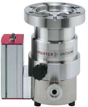
4 Turbopumps TMH 071 Y P/TMU 071 Y P with the TC 100 form a complete unit. Voltage is supplied by the power unit (see Accessories ). Turbomolecular Drag Pump TMU 071 Y P with TC High vacuum flange 2 Fore vacuum flange 4 Venting Valve 6 Rubber foot 8 Electronic Drive Unit TC 100 Ambient conditions The turbomolecular pump needs to be installed in compliance with the following ambient conditions: Installation location: protected against the weather (rooms within buildings) Temperature: +5 C to +40 C Relative humidity of the air: max. 80 % at T 31 C up to max. 50% at T 40 C Air pressure: 77 kpa kpa Installation altitude: 2000 m max. Pollution degree: 2 Overvoltage category: II Connection voltage: 24 VDC ±5% Cooling Enhanced convection cooling with cooling unit (accessory), air cooling (accessory) or water cooling (accessory). Integrated protective measures against excess temperatures: The Electronic Drive Unit TC 100 reduces the rotor rotation speed. Bearings High vacuum side: Wear free permanent magnetic bearing. Fore vacuum side: Oil circulatory lubricated ball bearing with ceramic balls.
5 The Turbomolecular Pumps TMH 071 Y P/TMU 071 Y P may only be used for the purpose of generating vacuum. The turbopumps may only be used to pump those media against which they are chemically resistant. For other media the operator is required to qualify the pumps for the processes involved. If the process produces dust, the maintenance intervals must be specified accordingly and sealing gas must be used. If the pump to be operated with more then 50% of the permissible gas load, sealing gas must be used. The turbopump must be connected to a backing pump in accordance with Section 3.3. Only Pfeiffer Vacuum power units may be used to operate. The use of other power units requires the prior agreement of the manufacturer and equalization with the valid specification. The pumps with TC 100 may only be operated providing the ambient conditions in compliance with Protection Type IP 30 are observed. Feature TMH 071 Y P TMU 071 Y P High vacuum flange ISO-KF / ISO-K CF-F High vacuum seal Elastomer Metal Attainable final < mbar < mbar pressure (without baking-out) (with baking-out) Abbreviations on the type of the pump Suffix Y : Turbopump for fitting in all positions. Suffix P : Purge gas connection for the prevention of the ingress of aggressive gases into the motor and bearing arena. Turbomolekular pump with: - Electronic Drive Unit TC 100, - protecting cover for high vacuum flange, - protecting cover for fore vacuum flange, - only DN 63 ISO-K: 2 bracket screws. The following is regarded, inter alia, as improper: The pumping of explosive or corrosive gases. Operating the pumps in areas where there is a danger of explosion. Operating the pumps in areas where there is a danger of radioactivity. The pumping of gases and vapours which attack the materials of the pumps. The pumping of corrosive gases without sealing gas. The pumping of condensating vapours. Operations involving impermissibly high levels of gas loads. Operations with improper gas modes. Operations involving too high levels of heat radiation power (see Section 9. Technical Data ). Operating the pump in environments which require a protection class superior to IP 30. Installation of the pumps in systems where the turbomolecular pumps are subjected to impact-like stress and vibrations or the effect of periodically occurring forces. Operations without the use of cooling equipment. The use of other power units or accessories which are not named in this manual or which have not been agreed by the manufacturer. Improper use will cause all claims for liability and guarantees to be forfeited.
6 WARNING WARNING Do not carry out any unauthorised conversions or alterations to the turbopump. The operator must ensure that the electronik is integrated into an emergency safety circuit. The supply voltage of the electronic must be interrupted when releasing the emergency safety condition. For special requirements please contact Pfeiffer Vacuum. In case the rotor blocks suddenly, torque levels up to 820 Nmcan occur which need to be absorbed by the system and the high vacuum flange. Connection Box TCS 010 fasten on the Electronic Drive Unit TC 100 The maximum permissible rotor temperature of the pump is 80 C. If the vacuum chamber or parts in the vacuum chamber are heated, the values stated in the technical data relating to the level of heat which may be radiated into the pump must not be exceeded. If necessary, suitable shielding must be fitted in the vacuum chamber before the turbopump (constructional suggestions available on request). The temperature of the high vacuum flange must not exceed 120 C. Only remove the blank flange from the high and fore vacuum side immediately before connection. On Turbopumps TMH/TMU 071 Y P the lubricant reservoir is already fitted and filled. Where magnetic fields of > 3 mt are involved suitable shielding must be provided (available on request). Either enhanced convection, air or water cooling is necessary for operating the pump (please see "Accessories"). If the pump is baked out, the heating sleeve and the body of the pump must be insulated to prevent burns from accidental contact. Floor mounting of the turbomolecular pump is only admissible after consulting the manufacturer. The option to connect two of accessory components is provided on the Connection Box TCS 010 (please see Section 11. Accessories) which is secured into the Electronic Drive Unit TC 100. PLEASE NOTE PLEASE NOTE The person responsible for commissioning must ensure that the installation is carried out in accordance with the legal regulations and the pertinent industrial standards. The utmost cleanliness must be observed when fitting all high vacuum parts. Unclean components prolong the pumping time. All installations units for the flange must be with installation grease-free, dust free and drying. Use a Pfeiffer Vacuum splinter shield or protective screen The use of a Pfeiffer Vacuum splinter shield or protective screen in the high vacuum flange protects the turbopump against foreign bodies coming from the vacuum chamber but does reduce the volume flow rate as followed: Reduced volume flow rate in % N 2 He H 2 Splinter shield DN Protective screen DN Splinter shield DN
7 Connecting via a Pfeiffer Vacuum vibration compensator The high vacuum side can be flanged onto the vacuum chamber either directly or via a Pfeiffer Vacuum vibration compensator (see Section 11. Accessories). When using a Pfeiffer vacuum vibration compensator, suitable securing needs to be introduced capable of absorbing the energy of the rotor should it suddenly block, since the vibration compensator itself alone cannot absorb the occurring forces. Please consult the manufacturer. Bracket screw (ISO-K with ISO-K) A B C D E The maximum permissible temperature at the vibration compensator is 100 C. Installing the high vacuum flange In case the rotor blocks suddenly, torque levels up to 820 Nmcan occur which need to be absorbed by the system and the high vacuum flange. For installing the turbomolecular pumps to the high vacuum flange, the components listed in the following must be used exclusively. Otherwise the turbomolecular pump may twist or tear off. The clamps, bolts, nuts and centering rings are special designs from Pfeiffer Vacuum The minimum strength of 170 N/mm 2 of the flange material needs to be observed. Installation is done as follows: ISO-K flange with ISO-K flange The components for installation are enclosed in the appropriate set of mounting material (see sec. 11. Accessories). ISO-K flange Bracket screw Centering ring, coated Splinter shield Protective screen ISO-K flange with ISO-F flange WARNING Claw grip (ISO-K with ISO-F) A B C D E ISO-K flansch Claw grip Centering ring, coated Splinter shield Protective screen See that the sealing surface is not damaged. Flange the turbopump according to the drawing and the component parts in your set of mounting material. Use 4 claw grips. Tighten the claw grips crosswise in three steps. Tightening torque: 16 ±1 Nm ISO-KF flange with ISO-KF flange For installing the following components are available. WARNING If the pumps are secured with an ISO-K flange on a vacuum chamber with an ISO-F flange it can come to twisting at the flange in case the rotor blocks suddenly. The components for installation are enclosed in the appropriate set of mounting material (see sec. 11. Accessories). If the pumps are secured with this attachment it can come to twisting the flange in case the rotor blocks suddenly. Connection nominal- Designation Order number diameter DN 40 ISO-KF Clamping ring for metal seal PF T Centering ring PF T Splitter shield PM X Clamping ring for metal seal See that the sealing surface is not damaged. Flange the turbopump according to the drawing and the component parts in your set of mounting material. Use 4 bracket screws. Tighten the bracket screws crosswise in three steps. Tightening torque: 25 ±2 Nm The screws on the clamping ring need to be tightened with a tightening torque of 3.7 Nm.
8 CF-F flange Applications for installing an CF-F to an CF-F flange are Stud screw with blind hole and Hexagon screw and clearance hole. The following items are needed: the particular set of mounting material and a copper seal. Using asplinter shield or protective screen is optional. PLEASE NOTE Stud screw with blind hole If used: Insert the splinter shield and protective screen in the high vacuum flange with the clamping lugs downward (towards the pump). Bring the seal centric into the correct position. Connect the flanges via 8 pieces of stud screws (M8) with washers and nuts. The stud screws need to be tightened revolving with a tightening torque of 22 ±2 Nm. Control the torque afterwards, because of the sealing material s flowing a retightening of the screws may be required. Stud screw with blind hole A B C CF-F flange Stud screw with washer and nut Copper seal Don t touch the copper seal with bare hands, this may affect the sealings efficiency. See that the sealing lip is not damaged. Hexagon screw and clearance hole If used: Insert the splinter shield and protective screen in the high vacuum flange with the clamping lugs downward (towards the pump). Bring the seal centric into the correct position. Connect the flanges via 8pieces of hexagon screws (M8) with washers and nuts. The hexagon screws need to be tightened revolving with a tightening torque of 22 ±2 Nm. Control the torque afterwards, because of the sealing material s flowing a retightening of the screws may be required. Hexagon screw and clearance hole A B C CF-F-flange Hexagon screw with washer and nut Copper seal The components for installing to an CF-F flange are to be ordered under the following numbers: Connection nominal- Designation Order-number diameter DN 63 CF-F Hexagon screw M8 with PF T washer and nut (25 pieces 1) ) Stud screw M8 with PF T washer and nut (18 pieces 1) ) Copper seal (10 pieces 1) ) PF T or copper seal silvered PF T (10 pieces 1) ) Splinter shield PM Protective screen PM ) supplied pieces
9 Directly flanging the pump The high vacuum flange of the turbopumps in Y version can be fitted in all positions. With horizontal pump installation and oil-sealed backing pumps (e.g. rotary vane pumps) the fore-vacuum flange of the turbopump should be aligned vertically downwards (maximum deviation ±20 ), otherwise the turbopump could become dirty due to backstreaming of rotary vane pump oil. Permissible installation positions for the turbopump 11 Vacuum chamber V Backing pump: Recommendation: Vacuum pressure 10 mbar; with enhanced convection cooling < 0,1 mbar. Oil-Free Diaphragm Pump or Rotary Vane Vacuum Pumps from the Pfeiffer Vacuum range (note installation position, turbopump, see Section 3.2.). Connecting the backing pump All connections of the fore vacuum line: with the usual small flange components or hose screw connections. Be sure to conduct away the exhaust gases from the backing pump. Do not reduce the free cross section of the fore vacuum flange with following components. H H H WARNING The exhausted process gases and vapours can represent a health hazard and can also be environmentally damaging. Comply with all the gas manufacture's safety instructions. V H The maximum loading capacity of the high vacuum flange is 200 N (equivalent to 20 kg). Assymetric loading on the high vacuum flange must be avoided. V V With rigid pipe connections: fit a bellows in the connecting line to reduce vibration. The fore vacuum pump is controlled via a relay box (accessory) and Connection Box TCS 010 (accessory) or in accordance with the connections diagram (please refer to Section 3.13). Please refer to Operating Instructions PT 0030 BN for details on the relay box, backing pump and its installation and to Operating Instructions PT 0045 BN for details on the Connection Box TCS 010. Installation position with oil-sealed backing pump 11 Vacuum chamber No forces from the piping system must be allowed to act on the pump where turbopumps are anchored. Suspend or support all pipes to the pump.
10 Turbopumps TMH 071 Y P/TMU 071 Y P can optionally be provided with enhanced convection cooling, air cooling or water cooling. The turbopumps must be operated with air or water cooling where the fore vacuum pressure is increased (> 0.1 mbar) and/or operations with gas loads. Air cooling may only be used where the ambient temperature is < 40 C. Use and installation For water cooling please refer to Operating Instructions PM 0546 BN. Permissible installation positions for the cooling unit where convection cooling is involved please see Section 9.1. Dimensions Diagram. For air cooling please refer to Operating Instructions PM 0543 BN. The electrical connection for the air cooling is effected via the control lead in the connection Out1 of the TCS 010 or in accordance with the connections diagram (please see Section 3.13.). In order to accelerate attainment of final pressures, turbopumps and vacuum chambers can be heated. Baking out is only practical on pumps with stainless steel casings (TMU pumps). On account of their aluminium casings, the temperatures attainable on TMH pumps are not high enough. Heating duration is dependent on the level of contamination and the required final pressure but should be at least four hours. PLEASE NOTE Where casing heating is involved the turbopump must be water cooled. The temperature of the high vacuum flange must not exceed 120 C (additional references please see Section 3.1.). The venting valve (accessory) provides automatic venting in the event of a power failure and switching off. Fitting the venting valve Unscrew the venting screw from the venting connection of the turbopump. Screw in venting valve with seal (USIT ring) on hexagonal SW 14. Electrical connection Plug control lead into the connection Out2 of the TCS 010 or in accordance with the connections diagram (please see Section 3.13.). For Details please refer to Operating Instructions for the Connection Box TCS 010, PT 0045 BN. The venting mode of the venting valve is selected via DCU, HPU or PC (using the Serial Interface RS 485). The maximum pressure at the venting valve is 1.5 bar absolute. WARNING High temperatures are generated when turbopumps are heated. There is a danger of injury from coming into contact with hot parts even after the casing heating has been switched off. Heating sleeve and the pump casing should be thermally insulated during the installation. During the heating phase be careful not to come into contact with the heating sleeve or the pump casing. Casing heating control is effected via the TCS 010 (please refer to Operating Instructions PT 0045 BN for the TCS 010) or in accordance with the connections diagram (please see Section 3.13.). For details regarding the casing heating and its installation please refer to Operating Instructions PM 0542 BN. Please refer to Operating Instructions PM 0507 BN for details on Venting Valve TVF 005.
11 It is necessary to operate the turbopump using sealing gas which affords protection for the turbopump, particularly where corrosive and dusty processes are involved. Even in non-corrosive processes, from 50% of the maximum gas load sealing gas should be used to ensure rotor cooling. Connection is made via a sealing gas valve 66 (please see Section 11. Accessories). Please refer to Operating Instructions PM 0229 BN for details on installing the sealing gas valve and adjusting the sealing gas flow. Connecting the sealing gas valve 9 Locking screw sealing gas connection 15 Seal 66 Sealing gas valve 66a Seal
12 PLEASE NOTE The turbopump and the Electronic Drive Unit TC 100 are connected and together form a single unit. Connecting cable 8a has to be ordered separately (for cable with bridge please see Accessories ). Voltage may only be supplied with the Pfeiffer Vacuum power units (please see Sectin 11. Accessories). The use of other power units requires the prior agreement of the manufacturer and equalization with the valid specification (power unit specifications available on request). Connecting without DCU Connect plug X3 on connecting cable 8a with connection X3 on the TC 100 and secure with screw 8b. Connect plug X2 on connecting cable 8a with Power Unit TPS 100 ( Accessories ) on connection X2 (please refer to Section Connection Diagram). For further details regarding Power Unit TPS 100 please refer to Operating Instructions PM 0521 BN. The mains connection must be freely accessible at all times. Once operations voltage has been supplied, the Electronic Drive Unit TC 100 performs a self test on the supply voltage. The supply voltage for Turbomolecular Pumps TMH/TMU 071 Y P is 24 VDC ±5% in accordance. (Connecting with DCU 001/DCU 100 please refer to Operating Instructions PM 0477 BN.) The Operating And Display Control Unit DCU 001, DCU 100 or HPU 001 can be connected via a TCS 010 (accessory) or a connecting cable TC 100/DCU - TPS (accessory). Please refer to the permissible operating instructions and Section Connection Diagram. Connecting the Electronic Drive Unit TC 100 with Power Unit TPS 100 X1 Mains connection X2 Connection, power unit X3 Connection TC 100 S1 ON/OFF switch 8 Electronic Drive Unit TC 100 8a Connecting cable, TC 100 TPS 100 8b Screw 105 Power Unit TPS 100
13 Remote control options for various functions are available via connection plug X3 (Pin 2 Pin 6) on the TC 100. Shielded cable must be used. The shielding on the plug side of the Electronic Drive Unit TC 100 should be connected to the metal cap on the plug. Inputs 2-6 are activated by supplying +24 VDC* from Pin 7 (active high) (please refer to Section Connections Diagram). Pin arrangement and functions of the 15 pole plug X3 (please refer to the following table) Pin Arrangement And Functions Of Plug X3 Pin nr. Function 1 Supply voltage +24 VDC ±5% (I dauer = 4,2 A; I max = 4,6 A) Inputs: Open (low) Closed (high) 2 Input remote/local 1) Remote: priority of Serial Interface RS 485 Local: priority of inputs (Pin 3-6) 3 Input accessory 1 4 Input accessory 2 not vent or heating OFF vent or heating ON 5 Input pumping station Pumping station OFF Pumping station ON: turbopump, backing pump and fan are switched ON 6 Input standby/reset Standby OFF Standby ON: Pump is accelerated to 66% of the nominal rotation speed. Reset: By supplying a pulse (T < 2 s) with an amplitude of 24 V a malfunction acknowledgement can be processed VDC* Outputs: low (0 V) high (24 V) 8 Switch output 1 Rotation speed switchpoint not attained Rotation speed switchpoint attained: Output can be loaded with 24V/50mA 9 Switch output 2 Collective error message trouble free operating: Output can be loaded with 24V/50mA 10 Accessory output 1 Accessory OFF Accessory ON Works setting: fan 11 Accessory output 2 Accessory OFF Accessory ON Works setting: automatic venting 12 Analog output 0-10 VDC = 0-100% *f end (optional current/power) 13 Serial Interface RS 485 D + (DO/RI) 14 Serial Interface RS 485 D - (DO/RI) 15 Mass (ground) 1) Only possible with activated parameter 028. No function on delivery.
14 The connection of the Display And Operating Unit DCU 001, DCU 100 or HPU001is possible via the Connection Box TCS 010 or cable TPS - TC 100/DCU or HPU (please see Section 11. Accessories), Please refer to the relevant Operating Instructions for the - TCS 010, PT 0045 BN, - DCU 001, PM 0477 BN or - HPU 001, PT 0101 BN. Connection to a fixed bus system Connect all units with D+ (Pin 13/X3) and D- (Pin 14/X3) on the bus. The bus must be closed at both ends. The connections must be made in accordance with the Serial Interface RS 485 specifications. Pin Arrangement 1 not connected V output (loadable with 210 ma) 3 not connected 4 not connected 5 RS 485: D+ (DO / RI) 6 Gnd 7 RS 485: D- (DO / RI) 8 not connected RS View from the TCS 010 plug side) All units connected to the bus must have differing serial interface addresses (parameter 797). An external computer can be connected directly to Serial Interface RS 485 via connection X3 (Pin 13, Pin 14). The group address of the Electronic Drive Unit TC 100 is 950. WARNING Only safety low voltage may be connected to the Serial Interface RS 485. Designation Value Pin 13: D+ Pin 14: D- Serial interface type: RS 485 Baud rate: 9600 Baud Data file word length: 8 bit Parity: no parity Start bits: 1 Stop bits: 1..2 All switched on remote control functions have priority over the serial interface functions. PLEASE NOTE For further details regarding the operation of the Serial Interface RS 485 and its electrical data please refer to separate Operating Instructions PM 0488 BN. PLEASE NOTE It is possible to connect an RS 232 (e.g. PC) via a level converter (please see Accessories ). Profibus DP Gateway TIC 250 is available (accessory) for connecting an Electronic Drive Unit TC 600 to a Profibus DP. Please refer to the respective Operating Instructions PM 0599 BN for detailed information on the operation of the TIC 250.
15 PM S

16 Sections 4.1. to 4.3. relate only to pump operations in the condition on delivery without display and operating unit. WARNING Turbopump rotors turn at great speed. When the high vacuum flange is open there is a danger of personal injury and of damage to the pump resulting from the falling in of objects. Therefore, never operate the pump with an open high vacuum flange. With water cooling: open cooling water supply and check flow. Plug connecting cable 8a ( Accessory ) into the TC 100 and connect with Power Unit TPS 100 (please see Section 3.7.). Please note: The following works settings are programmed: Start-up time: 8 min Rotation speed switchpoint 80% Automatic venting 50% For further works settings please refer to the parameter overview in the operating instructions for the Pumping Operations With the DCU, PM 0547 BN. These settings can only be altered via Serial Interface RS 485 (DCU or PC) (please refer to the respective operating instructions). WARNING Take care when pumping hazardous gases. Take note of all safety recommendations of the gas manufacturer. Switch on the power unit with S1. After successful completion of the self-test on the TC 100 (duration approximately 10 seconds), the turbopump is depending on the cable used (see sec. 11 Accessories) ready to operate or starts operating. The turbopump is operated via remote control (please refer to section 4.3.). (Please refer to the table in Section and connection diagram in Section 3.13.) Remote control options are possible via inputs Pin 2 Pin 6/X3 on the TC 100. Shielded cable must be used. The shielding on the plug side of the Electronic Drive Unit TC 100 should be connected to the metal cap on the plug. Inputs 2-6 are activated when they are connected to 24 VDC* on Pin 7/X3 (active high). (Pin 2/X3) This input is used to determine whether the control should be effected via remote control inputs or Serial Interface RS 485 (only works in conjunction with parameter 028, please refer to Operating Instructions for Pumping Operations with the DCU, PM 0547 BN). (Pin 3/X3 and Pin 4/X3) The components backing pump and air cooling (connectable to the accessory outputs) are switched automatically. The remote control inputs Pin 3 and Pin 4 are then ineffective. If the outputs are programmed to venting valve or the heating there is the option with the respective inputs venting release after the unit has been switched off and heating ON/OFF when the rotation speed switchpoint is exceeded. Works setting: Out1 (Pin 3) = air cooling Out2 (Pin 4) = venting valve The accessory inputs and outputs can be assigned several functions via a DCU or the Serial Interface RS 485. Rear Side, TPS 100 S1 ON/OFF switch X1 Mains connection X2 Connection TC 100 F1 Fuse F2 Fuse (Pin 5/X3) Connected pumping station components are started (backing pump, air cooling) and the turbopump is set in motion after successful completion of the self-test (duration approximately 10 seconds). (Pin 6/X3) With the use of "standby" the turbopump can be operated optionally at 66% of the nominal rotation speed (standby ON) or with the nominal rotation speed (standby OFF). By supplying a pulse (T < 2s) with an amplitude of 24 V a
17 (Pin 8/X3 And Pin 9/X3) The switch outputs 1 and 2 can be loaded with maximum 24V/50 ma per output. The following functions are assigned to the switch outputs: Switch output 1: Active high after attainment of the rotation speed switchpoint. The switchpoint for the turbopump is set at 80% of the nominal rotation speed. It can be used, for example, for a signal "Pumpe betriebsbereit" ("pump ready to operate"). Switch output 2: Active low on collective error signal. The connection of a relay is made between Pin 15 (mass) and the respective switch output Pin 8 or Pin 9 (please refer to Section Connections Diagram). The maximum power is dependent on the type of gas. Two characteristic lines are available for any type of gas in order to fully exploit the power potential of the pump: "Gas-Mode 0" for gases with molecular mass 40 as, for example, Argon; "Gas-Mode 1" for all lighter gases. Set the applicable gas mode on the TC 100 via the DCU 001, DCU 100 or HPU 001 (please refer to Operating Instructions Pumping operations with The DCU PM 0547 BN). Works setting: Gas mode 0 WARNING Pumping gases with molecular mass 40 with the incorrect gas mode can cause damage to the pump. When pumping noble gasas heavier then Argon it can come to the destruction of the pump. Please contact the manufacturer before using such gases. (10/X3 and Pin 11/X3) The accessory outputs can be loaded with a maximum of 24 V/200 ma. The works setting on the accessory outputs are: Accessory output 1: A connected air cooling system is started. Accessory output 2: A connected venting valve is started if venting release has been transmitted via accessory input 2. Additional components can also be connected by respective selection via the DCU or the RS 485. For the vertex of the power characteristic line please refer to Section 9. Technical Data. Maximum power is applied when the pump starts in order to limit the time required. Once the set rotation speed is attained, switching to the selected power characteristic line is automatic. If the gas dependent maximum power is exceeded, the rotation speed is reduced until equilibrium between the permissible power and gas friction is attained. The power limitation serves to protect the pump against thermal overloading. In order to avoid rotation speed fluctuations it is recommended to set, in rotation speed setting mode, the equilibrium frequency or a somewhat lower frequency. Gas type characteristic line (Pin 12/X3) A rotation speed proportional voltage (0-10 VDC correspond to 0-100%*f end ) can be tapped via the analog output (load 10 kω). Additional functions (power, current) can be assigned to the analog output via a DCU or Serial Interface RS 485. $ &' ( )* +,- $&%' ( )* +,- %!!.!" # / * Water cooling is required if the pumps are to be operated with gas load. Where high level gas loads and rotation speeds are involved, the resulting friction subjects the rotor to the effect of great heat. To avoid over-heating, a power rotation speed characteristic line is implemented in the TC 100; this ensures that where maximum gas loads are involved, the pump will operate at any rotation speed without the danger of damage
18 Before coming to rest after switching off, the turbopump must be vented in order to prevent contamination. Close the fore vacuum. Switch off the turbopump with switch S1 on the power unit. Venting There are three possibilities to vent turbopump: Manual venting Open the venting screw (on delivery, screwed in) on the venting connection about one turn. Venting with the Venting Valve TVF 005 (accessories) Venting release via the remote control (please see Section 4.3.) or via the serial interface which is selectable via DCU or interface (see Operating Instructions, "Pumping Operations With The DCU", PM 0547 BN). Venting in two stages when the vacuum chamber should be vented as quickly as possible. First stage: venting with a pressure increase rate of 15 mbar/s for 20 seconds. Second stage: venting with an optionally large venting valve. The valve cross-section for a venting rate of 15 mbar/s must be compatible with the size of the vacuum chamber. Where small vacuum chambers are involved, the Pfeiffer Vacuum Venting Valve TVF 005 can be used for first stage venting. Shut off water supply (if installed). WARNING If aggressive or hazardous gases are pumped there is a danger of personal injury resulting from coming into contact with process gases. Before removing a turbopump from the system, first: Vent the turbopump with a neutral gas or dry air. Ensure that there is no residual process gas in the system nor in the feeder lines. If the turbopump is to be shut down for more than a year: Remove turbopump from the system. Change the lubricant reservoir (see Section 7.1.) PLEASE NOTE Lubricant TL 011 should not be used when there have been no operations for 3 years. Close the high vacuum flange and evacuate the turbopump via the fore vacuum flange. Vent turbopump via the venting connection with nitrogen or dry air. Close fore vacuum and venting connection by blank flanging. Place the pump vertically on its rubber feet. The pump must be stored in buildings within a temperature range of -25 C to +55 C. In rooms with moist or aggressive atmospheres, the turbopump must be air-sealed in a plastic bag together with a bag of dessicant. PLEASE NOTE If the pump has been shut down for 3 years, the bearing must be changed (please contact Pfeiffer Vacuum Service). Operations with the DCU 001, DCU 100 or HPU 001 should be carried out in accordance with the relevant Operating Instructions: - PM 0477 BN (DCU description), - PM 0547 BN (operating the pump with the DCU), - PT 0101 BN (Display And Operating Unit HPU 001).
19 Certain operations modes of the turbopump and the TC 100 can be ascertained via the two integrated LEDs located on the front panel of the Electronic Drive Unit TC 100. The following operations modes are displayed: LED Cause Where impermissible motor temperatures are involved or the temperature of the casing is too high, the motor current is reduced. This can lead to dipping below the set rotation speed switchpoint and results in the turbomolecular pump being switched off. LED on the TC 100 glows red: Collective malfunction. green red Glows Power supply OK Function pumping station ON carried out Flashes Power supply OK Pumping station OFF Blinks Mains power supply failure Glows Blinks Collective malfunction (for example, run-up time error, over-temperature, turbopump or TC 100) Switching output 2 active (low) Warning (e.g. supply voltage short circuit to earth, mains power failure) PLEASE NOTE Differentiated malfunction and warning signals are only possible with the use of the DCU.
20 Problem Possible Causes Remedy Pump doesn't start; Power supply interrupted Check fuse in the power supply None of the integrated LEDs Check plug contacts on the mains glow on the TC 100 power supply Check power supply feeder line Check voltage on the power supply (24 VDC) at connection X2 Incorrect operations voltage supplied Supply correct operations voltage Pins 3,4,5 and 7 on the Plug X3 Connect pins 3,4,5 and 7 on the not connected plug X3 No supply of operations voltage Check plug contacts on the power supply Defect TC 100 Inform Pfeiffer Vacuum Service of need for repair Reduction in the voltage in the cable Use suitable cable Pump doesn't attain nominal Fore vacuum pressure too high Check backing pump function rotation speed within the set Leak or too much gas Check seals run-up time Seek leak and repair Pump cuts out during operations Reduce supply of process gas Rotor sluggish caused by Check bearing (noises?):inform defective bearing Pfeiffer Vacuum Service TC run-up time too short Set longer start-up time with the DCU, HPU or PC Thermal overloading caused by Water flow insufficient Ensure free flow Insufficient air supply Ensure adequate air supply Fore vacuum pressure too high Reduce fore vacuum pressure Ambient temperature too high Reduce ambient temperature Pump doesn't attain final pressure Pump dirty Bake out pump If seriously contaminated: Request Pfeiffer Vacuum Service to clean Leak in vacuum chamber, Seek leak starting with vacuum chamber lines or pump Repair leak Unusual operating noises Bearing damaged Inform Pfeiffer Vacuum Service of need for repair Rotor damaged Inform Pfeiffer Vacuum Service of need for repair Splinter shield (if fitted) Check seat of splinter shield not seated firmly (see Section 3.2.) Red LED on the TC 100 glows Collective malfunction Reset via mains OFF/ON when the TMP is at standstill or remote pin 6 Different malfunction display with the DCU/HPU possible 1) Red LED on the TC 100 flashes Warning through: Different warning message with the DCU/HPU possible 1) Mains power failure Check power supply voltage Check power supply mains connection Supply voltage short circuit to earth 1) Without a DCU/HPU inform Pfeiffer Vacuum Service to check the cause of trouble. Check power supply voltage for short circuit earth Wrong setting for set rotation speed Enter 1500 Hz for parameter 777 (Parameter 777) (see operating instruction PM 0547 BN Pumping Operations With DCU ). If there is no DCU/HPU available contact Pfeiffer Vacuum Service.
 from the turbopump. The bearing should be changed every three years (request Pfeiffer Vacuum Service to change).")

21 PLEASE NOTE No liability for personal injury nor material damage will be accepted for damages and operational interruptions which have been caused by improper maintenance; in addition, all guarantees become invalid. Remove the Electronic Drive Unit TC 100 (8) from the turbopump. The bearing should be changed every three years (request Pfeiffer Vacuum Service to change). Where extreme operating conditions or unclean processes are involved, the replacement interval should be checked with your Pfeiffer Vacuum Service Center. You can change the Electronic Drive Unit TC 100 and the lubricant reservoir yourself. Please contact your Pfeiffer Vacuum Service for all other maintenance and service work. Apply no mechanical stress to the Electronic Drive Unit TC 100. Assemble the new Electronic Drive Unit TC 100 (order number please see Section 10. Spare Parts) on the turbopump and connect again. The turbopump and the TC 600 must only be disconnected from each other when the turbopump is completely at rest and the TC 600 has been disconnected from the power supply. Please take into account that after replacement the standard operating parameters are always pre-set. If your application requires different parameters, please modify accordingly in addition to the ones stated above. Remove the Electronic Drive Unit TC 100 from the turbopump as follows: Switch off the turbopump, vent to atmospheric pressure (see Section 4.5.) and allow to cool as necessary. If necessary, remove the turbopump from the system. Unscrew allen head screws 8c (2 pieces) from the electronic drive unit 8.

.")


22 Remove the Porex rods 89 (eight pieces) with tweezers.. The lubricant reservoir should be replaced at least every three years. Where extreme operating conditions or unclean processes are involved, the replacement interval should be checked with your Pfeiffer Vacuum Service Center. Switch off the turbopump, vent to atmospheric pressure (see Section 4.3.) and allow to cool as necessary. If necessary, remove the turbopump from the system. Unscrew rubber feet 6 from the underside of the pump. Unscrew locking cover 90 on the underside of the pump with installation tool E (order number N ). Both the lubricant reservoir and the Porex rods WARNING can contain toxic substances from the media being pumped. Lubricant reservoirs and Porex rods must be disposed of in accordance with local regulations. Safety instructions data sheet for the lubricant on request. Clean off any dirt on the pump and locking cover with a clean, fluff-free cloth. Insert new Porex rods (eight pieces) with tweezers. Insert new lubricant reservoir 92 up to the O-ring 93in the pump. The lubricant reservoir comes pre-filled with Lubricant TL 011; do not add additional lubricant. Lever out the lubricant reservoir 92 with the help of two screwdrivers. Screw in locking cover 90. The lubricant reservoir is brought into the correct axial position with the locking cover. Screw the rubber feet 6 back in.
23 Do make use of our service facilities In the event that repairs are necessary a number of options are available to you to ensure any system down time is kept to a minimum: Have the pump repaired on the spot by our Pfeiffer Vacuum Service Engineers; Return the pump to the manufacturer for repairs; Replace the pump. Local Pfeiffer Vacuum representatives can provide full details. PLEASE NOTE Please take into account that where Pfeiffer Vacuum Service replacement service is involved the standard operating parameters are always pre-set. If your application requires different parameters, please modify accordingly. The turbopump and the Electronic Drive Unit TC 100 form a single unit and must therefore be returned complete for repair purposes. Before returning the unit it should be ensured that the power supply is not the cause of the malfunction (checking the power supply). WARNING Decontaminate units before returning or possible disposal. Do not return any units which are microbiologically, explosively or radioactively contaminated. Returning contaminated units If contaminated have to be returned for maintenance/repair, the following instructions concerning shipping must be followed: Neutralise the pump by flushing with nitrogen or dry air. Seal all openings to the air. Seal pump or unit in suitable protective foil. Return equipment only in suitable, rugged shipping containers and by complying with the currently valid shipping regulations. PLEASE NOTE Repair orders are carried out according to our general conditions of sale and supply. If repairs are necessary, please send the pump to your nearest Pfeiffer Vacuum Service Center. Before returning: Dismantle all accessories. If the unit is free of harmful substances, please attach a clearly visible notice "Free of harmful substances" (both on the unit and also on the delivery note and any accompanying letters). "Harmful substances" are substances and preparations as defined in the current, local, dangerous substances regulations; in the U.S.A. as "materials in accordance with the Code of Federal Regulations (CFR) 49 Part Definition and Preparation". We will carry out the decontamination and invoice this work to you if you have not attached this note. This also applies where the operator does not have the facilities to carry out the decontamination work. Units which are contaminated microbiologically, explosively or radioactively cannot be accepted as a matter of principle. Fill out the declaration of contamination In every case the "Declaration of Contamination" must be completed diligently and truthfully. A copy of the completed declaration must accompany the unit; any additional copies must be sent to your local Pfeiffer Vacuum Service Center. Please get in touch with your local Pfeiffer Vacuum representatives if there are any questions regarding contamination.
24 Feature Unit TMH 071 Y P TMH 071 Y P TMU 071 Y P Connection nominal diameter Inlet DN 40 ISO-KF DN 63 ISO-K DN 63 CF-F Outlet DN 16 ISO-KF/G 1/4 DN 16 ISO-KF/G 1/4 DN 16 ISO-KF/G 1/4 Venting connection G 1/8 G 1/8 G 1/8 Nominal rotation speed Hz (1/min) 1500 (90 000) 1500 (90 000) 1500 (90 000) Standby rotation speed Hz (1/min) 1000 (60 000) 1000 (60 000) 1000 (60 000) Start-up time min Max. noise level 1) db (A) Final pressure, backing pump mbar < 10 < 10 < 10 Integral leak rate (He) 2) mbar l/s < < < Maximum permissible rotor temperature C Permissible heat radiation power W Volume flow rate for Nitrogen N 2 l/s Helium He l/s Hydrogen H 2 l/s Compression ratio for N 2 > > > He H 2 > Maximum fore vacuum pressure for N 2 mbar He mbar H 2 mbar Maximum gas throughput 3) With water cooling N 2 mbar l/s He mbar l/s With air cooling 4) N 2 mbar l/s Maximum gas throughput at intake pressure of 0.1 mbar 5) With warer cooling N 2 mbar l/s He mbar l/s H 2 mbar l/s Vertex power characteristics line 6) A W / Hz 80 / / / 1500 B W / Hz 80 / / / 1500 C W / Hz 60/ / / 1500 D W / Hz 80 / / / 1300 Final pressure 7) With rotary vane pumps mbar < < < With diaphragm pumps mbar < < < Lubricant TL 011 TL 011 TL 011 Maximum cooling water consumption with water at 15 C 8) l/h Cooling water temperature ÞC Permissible ambient temperature with air cooling C Heating power consumption W Weight kg Permissible magnetic field mt Operating voltage VDC 24 ± 5% 24 ± 5% 24 ± 5% Duration 8) - / max. current consumption A 4.1 / / / 4.6 Duration 8) - / max. power W 100 / / / 110 Fuse, internal V T8A/250 T8A/250 T8A/250 Protection class 9) IP 30 IP 30 IP 30 Shipping and storage temperature C -25 to to to +55 Relative humidity % 5-85 non-condensing 5-85 non-condensing 5-85 non-condensing 1) Distance from the pump 1 m 2) Measured at a helium concentration of 100 %, 10 s measurement time 4) Until ambient temperature 30 C. 5) Rotation speed of pump may drop below the nominal rotation speed.
25 TMH 071 Y P / TMU 071 Y P ! ! 7 7). ) /23 9 0& 9 0:; &< 9 4:; &< :; &< ( =4>
26 Pos. Description Pieces Size Number Comments Ordering Quantity Spare Parts TMH/TMU 071 Y P 8 Electronic Drive Unit TC PM C A see section Locking cover 1 PM X 91 O-ring 1 68x3 P PP 92 Lubricant reservoir 1 PM T see section 7.2 (with O-ring 93) Spare Parts
27 Description Size Number Comments/ Order Quantity Operating Instructions Components for cooling Dirt trap R 3/8 P R Recycled Water Cooling Unit TZK V, 50 Hz PM Z PM 0369 BN Air cooling 24 VDC PM Z A PM 0543 BN Water cooling PM T PM 0546 BN Cooling unit (for enhanced convection cooling) PM T Components for venting Venting Valve TVF 005, without current closed 24 VDC PM Z PM 0507 BN Drying Unit TTV 001 PM Z PM 0022 BN (filled with zeolite) Venting flange DN 10 ISO-KF PM T Components for heating Casing heating Components for mounting Water cooling required/ 230 V, Schuko plug PM T PM 0542 BN 208 V, UL-plug PM T PM 0542 BN 115 V, UL-plug PM T PM 0542 BN Coated centering ring, bracket screws DN 63 ISO-K PM T for mounting ISO-K/ISO-K Coated centering ring with protective screen, DN 63 ISO-K PM T for mounting ISO-K/ISO-K bracket screws Coated centering ring with splinter shield, DN 63 ISO-K PM T for mounting ISO-K/ISO-K bracket screws Coated centering ring, claw grips DN 63 ISO-K PM T for mounting ISO-K/ISO-F Coated centering ring with protective screen, DN 63 ISO-K PM T for mounting ISO-K/ISO-F claw grips Coated centering ring with splinter shield, DN 63 ISO-K PM T for mounting ISO-K/ISO-F claw grips Other accessories Connecting cable TC 100 TPS (without bridge)1) 3m PM T Other lengths on request; the TMP starts after switching on via DCU/HPU. Connecting cable TC 100 TPS (with bridge)1) 3m PM T Other lengths on request; the TMP starts when the power supply is switched on. Connecting cable TC 100/DCU - TPS1) 3 m PM T Other lengths on request Power supply TPS 100; for fitting to walls or standard runners PM T PM 0521 BN TPS 100; 19 insert unit PM T PM 0521 BN DCU 100; 19 insert unit with Operating and Display Control Unit (DCU) PM C PM 0477 BN Mains cable Schuko plug 230 V P ZA UL plug 208 V P ZF UL plug 115 V P ZE 15 pole D-Sub plug P Protection class IP 54 for TC 100 Operating and Display Control Unit DCU 001 PM T PM 0477 BN Operating and Display Control Unit HPU 001 PM T PT 0101 BN Connection Box TCS 010 PM T PT 0045 BN Relay box, backing pump V (5 A) PM T PT 0030 BN V (20 A) PM T PT 0030 BN Level Converter RS 232/485 PM T PM 0549 BN Profibus DP gateway TIC 250 PM T PM 0599 BN Vibration compensator, TMH DN 63 ISO-K PM X TMH DN 40 ISO-KF PM X TMU DN 63 CF-F PM X Splinter shield DN 40 ISO-KF PM X DN 63 CF-F PM Protective screen DN 63 CF-F PM Sealing gas valve PM Z PM 0229 BN Hose nipple for the sealing gas valve DN 16 ISO-KF-10 PF ) For application please refer to Section Connections Diagram When ordering accessories and spare parts please be sure to state the full part number. When ordering spare parts please state additionally the unit type and unit number (see
28 The repair and/or service of vacuum components will only be carried out if a correctly completed declaration has been submitted. Non-completion will result in delay. The manufacturer could refuse to accept any equipment without a declaration. This declaration can only be completed and signed by authorised and qualified staff: 1. Description of component: - Equipment type/model: - Code No.: - Serial No.: - Invoice No.: - Delivery Date: 2. Reason for return: 3. Equipment condition - Has the equipment been used? yes no - What type of pump oil was used? - Is the equipment free from potentially harmful substances? yes (go to section 5) no (go to section 4) 4. Process related contamination of equipment - toxic yes no - corrosive yes no - microbiological hazard*) yes no - explosive*) yes no - radioactive*) yes no - other harmful substances yes no *) We will not accept delivery of any equipment that has been radioactively or microbiologically contaminated without written evidence of decontamination! Please list all substances, gases and by-products which may have come into contact with the equipment: Tradename Chemical name Danger class Precautions associated Action if spillage or human Product name (or Symbol) with substance contact Manufacturer Legally Binding Declaration I hereby declare that the information supplied on this form is complete and accurate. The despatch of equipment will be in accordance with the appropriate regulations covering Packaging, Transportation and Labelling of Dangerous Substances. Name of Organisation: Address: Post code: Tel.: Fax: Telex: Name: Job title: Date: Company stamp: Legally binding signature:
 We hereby declare that the product cited below satisfies all relevant provisions of EC directive \"Machinery\" 2006/ 42/ EC.")
29 Declaration of conformity according to the EC directive: M achinery 2006/ 42/ EC (Annex II, no. 1 A) We hereby declare that the product cited below satisfies all relevant provisions of EC directive "Machinery" 2006/ 42/ EC. In addition, the product cited below satisfies all relevant provisions of EC directive "Electromagnetic Compatibility" 2004/ 108/ EC. The agent responsible for compiling the technical documentation is Mr. Jörg Stanzel, Pfeiffer Vacuum GmbH, Berliner Straße 43, Aßlar. TMH 071 Y P / TMU 071 Y P Guidelines, harmonised standards and national standards and specifications w hich have been applied: DIN EN ISO : 2004 DIN EN ISO : 2004 DIN EN ISO : 2007 DIN EN : 1996 DIN EN : 2002 Signatures: Pfeiffer Vacuum GmbH Berliner Straße Asslar Germany (M.Bender) Managing Director (Dr. M. Wiemer) Managing Director CE/2010
Betriebsanleitung Operating Instructions. Oil Mist Filter
 Betriebsanleitung Operating Instructions Oil Mist Filter ONF 4-20 idealvac.com (505)872-0037 idealvac.com PK 0169 BE/E (0906) Contents 1. Safety Instructions... 2 1.1. For Your Orientation... 2 2. Understanding
Netzteil Power Supply TPS TPS
 Netzteil Power Supply TPS 100 600 TPS 101-601 PFEIFFER VACUUM 2.1. Main Features Mains voltage is supplied via a mains cable with the following optional plugs: Power supply rear panel, TPS 300/301 as an
Swing Piston Compressors and Vacuum Pumps
 Swing Piston Compressors and Vacuum Pumps NPK 018 AC Pressure NPK 018 DC Pressure NPK 018 AC Vacuum NPK 018 DC Vacuum Operating and Installation Instructions Read and observe these Operating and Installation
Operating Instructions
 Translation of the original instructions HiPace 10 Turbopump Operating Instructions PT 0207 BEN/G (1209) EN Table of contents Table of contents 1 About this manual...............................................
HiPace 80 with TC 110, DN 63 CF- F
 HiPace 80 with TC 110, DN 63 CF- F HiPace 80 with TC 110, DN 63 CF-F Small yet powerful turbopump with a pumping speed of up to 67 l/s for N 2 Integrated TC 110 drive electronics For installation in any
Operating Instructions
 Translation of the original instructions ONF 16 S / ONF 25 S Oil Mist Filter Operating Instructions PD 0057 BEN/C (1301) EN Table of contents Table of contents 1 About this manual...............................................
HiPace 80 with TC 110, DN 63 ISO-K
 HiPace 80 with TC 110, DN 63 ISO-K HiPace 80 with TC 110, DN 63 ISO-K Small yet powerful turbopump with a pumping speed of up to 67 l/s for N 2 Integrated TC 110 drive electronics For installation in any
HiPace 60 P with TC 110, DN 63 ISO-K
 HiPace 60 P with TC 110, DN 63 ISO-K HiPace 60 P with TC 110, DN 63 ISO-K Small yet powerful turbo molecular pump without Holweck-stage with a pumping speed of up to 64 l/s for N 2 Integrated TC 110 drive
HiPace 300 Plus with TC 110, DN 100 ISO-K
 HiPace 300 Plus with TC 110, DN 100 ISO-K HiPace 300 Plus with TC 110, DN 100 ISO-K Compact yet powerful turbopump with a pumping speed of up to 260 l/s for N 2 Integrated TC 110 drive electronics Low
HiPace 30 with TC 110, DN 40 ISO-KF
 HiPace 30 with TC 110, DN 40 ISO-KF HiPace 30 with TC 110, DN 40 ISO-KF Similar Image Small yet powerful turbopump with a pumping speed of up to 32 l/s for N 2 Highest compression in this pumping speed
Operating and Installation Instructions Diaphragm Vacuum Pumps and Compressors
 Operating and Installation Instructions Diaphragm Vacuum Pumps and Compressors Type range: UN813.3ANI UN813.4ANI UN813.3ANDCB UN813.4ANDCB UN813.5ANI Fig. 1: UN813.3ANI Fig. 2: UN813.4ANI You have selected
HiPace 80 for TCP 350, DN 63 ISO-K
 HiPace 80 for TCP 350, DN 63 ISO-K HiPace 80 for TCP 350, DN 63 ISO-K Small yet powerful turbopump with a pumping speed of up to 67 l/s for N 2 External TCP 350 drive electronics For installation in any
HiPace 80 with TC 110, DN 40 ISO-KF
 HiPace 80 with TC 110, DN 40 ISO-KF HiPace 80 with TC 110, DN 40 ISO-KF Small yet powerful turbopump with a pumping speed of up to 35 l/s for N 2 Integrated TC 110 drive electronics For installation in
HiPace 300 with TC 110, DN 100 ISO-K
 HiPace 300 with TC 110, DN 100 ISO-K HiPace 300 with TC 110, DN 100 ISO-K Rugged, powerful turbopump with a pumping speed of up to 260 l/s for N 2 Integrated TC 110 drive electronics Ideal for analytical
HiPace 300 with TC 110 and power supply OPS 100, DN 100 ISO-K
 HiPace 300 with TC 110 and power supply OPS 100, DN 100 ISO-K HiPace 300 with TC 110 and power supply OPS 100, DN 100 ISO-K Similar Image Rugged, powerful turbopump with a pumping speed of up to 260 l/s
HiPace 300 Plus with TC 110, DN 100 ISO-F
 HiPace 300 Plus with TC 110, DN 100 ISO-F HiPace 300 Plus with TC 110, DN 100 ISO-F Compact yet powerful turbopump with a pumping speed of up to 260 l/s for N 2 Integrated TC 110 drive electronics Low
HV Gate Valve with pneumatic actuator
 HV Gate Valve with pneumatic actuator This manual is valid for the valve ordering number(s): 09134-_E14/24/34/44 09136-_E14/24/34/44 09138-_E14/24/34/44 09140-_E14/24/34/44 09144-_E14/24/34/44 The fabrication
Diaphragm Vacuum Pumps and Compressors
 Operating Instructions Read and observe these Operating Instructions! Diaphragm Vacuum Pumps and Compressors N022 AN.18 N022 AT.18 N022 AV.18 N026.1.2 AN.18 N026.1.2 AT.18 N026.1.2 AV.18 N026.3 AN.18 N026.3
Operating Instructions
 Translation of the original instructions ONF/R 035/065, ONF/R 035/065 C Oil mist filter Operating Instructions PD 0053 BEN/A (1101) EN Table of contents Table of contents 1 About this manual...............................................
Diaphragm Vacuum Pumps and Compressors
 Operating Instructions Read and observe these Operating Instructions! Diaphragm Vacuum Pumps and Compressors N145 AN.18 N145 AT.18 N145 AV.18 N145.1.2 AN.18 N145.1.2 AT.18 N145.1.2 AV.18 KNF Neuberger
OPERATING INSTRUCTIONS
 OPERATING INSTRUCTIONS EN HIPACE 10 Turbopump Translation of the original instructions PT 0207 BEN/I (1603) Table of contents Table of contents 1 About this manual...............................................
Pressure chlorine changeover unit C 7520
 BW 2 24 04 / 1 Content 1. Scope of delivery 2. Device description 3. Installation 4. Operation 5. Shutdown 6. Maintenance 7. Troubleshooting 1 Scope of delivery The chlorine gas changeover unit C 7520
Swing Piston Compressors and Vacuum Pumps
 Swing Piston Compressors and Vacuum Pumps NPK 050 NPK 0100 Operating and Installation Instructions Read and observe these Operating and Installation Instructions! KNF Neuberger GmbH Alter Weg 3 D-79112
User Guide. Lubricus Lubrication System LUB-D1/LUB-D2/LUB-D3/LUB-D4 (24 VDC)
") User Guide Lubricus Lubrication System LUB-D1/LUB-D2/LUB-D3/LUB-D4 (24 VDC) version 04/2013 Content General Information 3 Warning 3 Scope of Supply 3 Overview 3 General safety details 4 Intended use 4
User Guide Lubricus Lubrication System LUB-D1/LUB-D2/LUB-D3/LUB-D4 (24 VDC) version 04/2013 Content General Information 3 Warning 3 Scope of Supply 3 Overview 3 General safety details 4 Intended use 4
Installation, Operating & Maintenance Instructions. HV gate valve with pneumatic actuator. Series 110 DN mm (I. D.
 Installation, Operating & Maintenance Instructions HV gate valve with pneumatic actuator Series 110 DN 250 320 mm (I. D. 10" 12") This manual is valid for the following product ordering numbers: 11048-.
Control Gate Valve with stepper motor actuator
 Control Gate Valve with stepper motor actuator This manual is valid for the valve ordering numbers: 64036-.E52 and 64040-.E52 The respective product identification is given on each valve in the following
Operating manual Separator
 Operating manual Separator Sheet no. AS/4.1.141.1.1 issue 20.08.2014 Contents Section Title Page 0 Introduction... 1 1 Intended use......1 2 Marking of the fitting... 1 3 Safety instructions... 2 4 Transport
ULTRASONIC FLOW SENSOR QALCOSONIC FLOW 2
 AB AXIS INDUSTRIES ULTRASONIC FLOW SENSOR QALCOSONIC FLOW 2 TECHNICAL DESCRIPTION, INSTALLATION AND USER INSTRUCTIONS PESF2V01 KAUNAS Contents Page SAFETY INFORMATION... 1. APPLICATION FIELD... 2. TECHNICAL
Installation, Operating & Maintenance Instructions. Series 081, DN (I.D. 2½" - 4") Hot surfaces; do not touch!
 Hot surfaces; do not touch!") Vacuum Gate Valve This manual is valid for the valve ordering number(s): 08136-FA14/24/34/44 08138-FA14/24/34/44 08140-FA14/24/34/44 The fabrication number is indicated on each product as per the label
Vacuum Gate Valve This manual is valid for the valve ordering number(s): 08136-FA14/24/34/44 08138-FA14/24/34/44 08140-FA14/24/34/44 The fabrication number is indicated on each product as per the label
FL 10 DIAPHRAGM PUMP INSTALLATION INSTRUCTIONS. Before operating the pump, please read the Installation Instructions and safety precautions.
 FL 10 INSTALLATION INSTRUCTIONS DIAPHRAGM PUMP FL 10 DC-P FL 10 AC Before operating the pump, please read the Installation Instructions and safety precautions. Installation Instructions FL 10 Table of
Installation, Operating & Maintenance Instructions. UHV gate valve with pneumatic actuator. Series 108 DN mm (I. D. 2½ 8 )
") Installation, Operating & Maintenance Instructions UHV gate valve with pneumatic actuator Series 108 DN 63 200 mm (I. D. 2½ 8 ) This manual is valid for the following product ordering numbers: 108.. -.
Installation, Operating & Maintenance Instructions UHV gate valve with pneumatic actuator Series 108 DN 63 200 mm (I. D. 2½ 8 ) This manual is valid for the following product ordering numbers: 108.. -.
Mini UHV gate valve with manual actuator with pneumatic actuator
 Mini UHV gate valve with manual actuator with pneumatic actuator This manual is valid for the valve ordering numbers: 004/8/3/34-. E0/08 004/8/3/34-. E//3/4 004/8/3/34-. E//3/4 004/8/3/34-. E4/4/34/44
Compact System NRGS 11-2 NRGS Original Installation Instructions English
 Compact System NRGS 11-2 NRGS 16-2 EN English Original Installation Instructions 810366-05 1 Contents Important Notes Page Usage for the intended purpose...4 Safety note...4 LV (Low Voltage) Directive
Diaphragm-Gas Sampling Pumps
 Diaphragm-Gas Sampling Pumps N 143 ANE N 143 ATE Operating and Installation Instructions Read and observe these Operating and Installation Instructions! N 186.1.2 ANE N 186.1.2 ATE KNF Neuberger GmbH Alter
Instruction Manual. Sewage lifting station compli 300
 Instruction Manual Sewage lifting station compli 300 Safety instructions Areas of application Electrical connection Installation Servicing Technical data Appendix JUNG PUMPEN GmbH Industriestr. 4-6 33803
Operating Instructions
 Operating Instructions BE2700 Brinkmann Immersions pumps of the series TA/STA/TAL/SAL901... 1303 Contents 1 General...1 2 Safety...2 3 Transport and storage...2 4 Description of product and accessories...2
Operating Instructions
 Translation of the original instructions MVP 015-2 Diaphragm Pumps Operating Instructions PU 0012 BEN/G (1302) EN Table of contents Table of contents 1 About this manual...............................................
ISP-500B. Oil-free Scroll Vacuum Pump. Instruction Manual. View our inventory. Record of Pump Information. Serial Number: Purchase date:
 ISP-500B Oil-free Scroll Vacuum Pump Instruction Manual View our inventory Serial Number: Record of Pump Information Purchase date: In Service date: Dealer information: IM-500B 1/3/07 Page 1 of 26 Important
FF 20 DIAPHRAGM PUMP INSTALLATION INSTRUCTIONS
 FF 20 INSTALLATION INSTRUCTIONS DIAPHRAGM PUMP FF 20 DCB-4 FF 20 DC-M Before operating the pump and the accessories, please read the Installation Instructions and safety precautions. Installation Instructions
Installation, Operation, and Maintenance Manual
 Industrial Process Installation, Operation, and Maintenance Manual Series PBV Plastic Lined Ball Valve Table of Contents Table of Contents Introduction and Safety...2 Safety message levels...2 User health
MVP DC / MVP DC
 OPERATING INSTRUCTIONS EN MVP 020-3 DC / MVP 030-3 DC Diaphragm Pumps Translation of the original instructions PU 0065 BEN/D (1607) Table of contents Table of contents 1 About this manual...............................................
Safety Guideline for Turbomolecular Pumps Turbomolecular pumps as described in the following operating manual contain a large amount of kinetic energy
 16 Instructions for Use Safety Guideline for Turbomolecular Pumps 226 General Information 227 Storage 229 Preparation for installation 230 Installation 232 Pump Fixing234 Use of TwisTorr 304 FS 235 Maintenance
HV-Angle Valve (Series 264) HV-InlineValve (Series 265) with electromagnetic actuator single acting with closing spring (NC)
 HV-InlineValve (Series 265) with electromagnetic actuator single acting with closing spring (NC)") HV-Angle Valve (Series 264) HV-InlineValve (Series 265) with electromagnetic actuator single acting with closing spring (NC) This manual is valid for the valve ordering number(s): 26... 26428 -K A 61 A..
HV-Angle Valve (Series 264) HV-InlineValve (Series 265) with electromagnetic actuator single acting with closing spring (NC) This manual is valid for the valve ordering number(s): 26... 26428 -K A 61 A..
INSTRUCTION MANUAL. I/P Converter DSG BXXY3Z DSG BXXY4Z
 INSTRUCTION MANUAL I/P Converter DSG BXXY3Z DSG BXXY4Z Revision 2.0 3.626 016136 en Page 1/15 Should you have any questions concerning the I/P converter, please contact the Service Department of the Product
Operating Instructions
 Translation of the original instructions DUO 3 / DUO 3 M Rotary Vane Pump Operating Instructions PD 0060 BEN/C (1308) EN Table of contents Table of contents 1 About this manual...............................................
Diaphragm Vacuum Pump
 Diaphragm Vacuum Pump with Diaphragm Stabilization System Operating Instructions Read and observe these Operating Instructions! N 920 AP.18 N 920 AP.29.18 N 920 KT.29.18 KNF Neuberger GmbH Alter Weg 3
Betriebsanleitung Operating Instructions. Diaphragm Pump
 Betriebsanleitung Operating Instructions Translation of the Original Operating Instructions Diaphragm Pump idealvac.com (505)872-0037 idealvac.com MVP 015-4 PK 0202 BE/E (1001) Index Page 1. Safety Precautions...
Micro Diaphragm Gas Sampling Pumps
 Operating and Installation Instructions Micro Diaphragm Gas Sampling Pumps Type range: NMP830K_DC-M HP NMP830.1.2K_DC-M HP NMP830K_DC-B HP NMP830.1.2K_DC-B HP NMP830K_DC-B4 HP NMP830.1.2K_DC-B4 HP You
Installation, Operating & Maintenance Instructions. HV angle valve with pneumatic actuator single acting with closing spring (NC)
") Installation, Operating & Maintenance Instructions HV angle valve with pneumatic actuator single acting with closing spring (NC) Series 264 DN 10 50 mm (I. D. ⅜" 2") HV inline valve with pneumatic actuator
Installation, Operating & Maintenance Instructions HV angle valve with pneumatic actuator single acting with closing spring (NC) Series 264 DN 10 50 mm (I. D. ⅜" 2") HV inline valve with pneumatic actuator
Diaphragm Vacuum Pumps and Compressors
 Diaphragm Vacuum Pumps and Compressors N 035 ANE N 035 AN.9 E N 035 ATE N 035 AVE N 035 AV.9 E N 035 SNE N 035 STE N 035 ST.9 E N 035 SVE Operating and Installation Instructions Read and observe these
Assembly and Maintenance Manual Type ASNU
 Assembly and Maintenance Manual Type ASNU Hatschekstr.36 69126 Heidelberg Germany Tel +49(0)6221 30470 Fax +49(0)6221 304731 info@stieber.de www.stieber.de Date of issue: 30.05.2018 GB Revision: 0 U:\EngUsers\!ProduktDoku\1AAA_Einbauerklaerung_Wartungsanleitung_Konformitaetserklaerung\1AAA_Wartungsanleitungen\Orginal_Worddatei\_ASNU.docx
Technical Documentation
 Technical Documentation Product manual Holding brake controller Document: 0198441113316 Edition: V1.00, 03.2006 Important information The drive systems described here are products for general use that
Betriebsanleitung Operating Instructions. Piston Vacuum Pump
 Betriebsanleitung Operating Instructions Translation of the Original Operating Instructions Piston Vacuum Pump PU 0044 BE/E (1005) XtraDry TM 150-2 XtraDry TM 250-1 Article no.: PO P01 150... 152 PO P01
Installation, Operation, and Maintenance Manual
 Industrial Process Installation, Operation, and Maintenance Manual Series PBFV Plastic Lined Butterfly Valve - Lug and Wafer Style Table of Contents Table of Contents Introduction and Safety...2 Safety
HV angle valve with single acting pneumatic actuator and closing spring (NC)
") Installation, Operating & Maintenance Instructions HV angle valve with single acting pneumatic actuator and closing spring (NC) Series 264 DN 100 160 mm (I. D. 4 6 ) This manual is valid for the following
Installation, Operating & Maintenance Instructions HV angle valve with single acting pneumatic actuator and closing spring (NC) Series 264 DN 100 160 mm (I. D. 4 6 ) This manual is valid for the following
Assembly and Maintenance Manual Type AS
 Assembly and Maintenance Manual Type AS Hatschekstr.36 69126 Heidelberg Germany Tel +49(0)6221 30470 Fax +49(0)6221 304731 info@stieber.de www.stieber.de Date of issue: 30.05.2018 GB Revision: 0 U:\EngUsers\!ProduktDoku\1AAA_Einbauerklaerung_Wartungsanleitung_Konformitaetserklaerung\1AAA_Wartungsanleitungen\Orginal_Worddatei\_AS.docx
1. SPECIFICATION. Altitude of motor installation. Information: Resistance and temperature specifications of the PTC thermistor / posistor/.
 1. SPECIFICATION 5 GENERAL INFORMATION Motors with parameters according to the data sheet comply with the requirements of the IEC 60034-1 standard, and IEC 60034-30 class efficiency IE2 Motor versions:
Operating and Installation Instructions Diaphragm Gas Sampling Pumps
 Operating and Installation Instructions Diaphragm Gas Sampling Pumps UN026FT.16I UN726FTI UN726FT.29I KNF Neuberger, Inc 2 Black Forest Rd Trenton, NJ 08691-1810 Phone: 609-890-8600 Fax: 609-890-8323 www.knf.com/usa.htm
Accessories for Wind Power Inverter WINDY BOY PROTECTION BOX 400 / 500 / 600
 Accessories for Wind Power Inverter WINDY BOY PROTECTION BOX 400 / 500 / 600 Installation Guide WBP-Box-IEN103320 IMEN-WBP-BOX Version 2.0 EN SMA Solar Technology AG Table of Contents Table of Contents
Angle seat valve with piston actuator VZXA-...-K
 Angle seat valve with piston actuator VZXA-...-K Festo AG & Co. KG Postfach 73726 Esslingen Germany +49 711 347-0 www.festo.com 3 Further information Accessories www.festo.com/catalogue Spare parts www.festo.com/spareparts
Installation, Operating & Maintenance Instructions. All-metal gate valve with compact or extended pneumatic actuator
 Installation, Operating & Maintenance Instructions All-metal gate valve with compact or extended pneumatic actuator Series 48 DN 16 320 mm (I.D. ⅝" 12") This manual is valid for the following product ordering
D58 Series Brake Instructions
 D58 Series Brake Instructions 4740 W. Electric Avenue Milwaukee, WI 53219 414/672-7830 FAX 414/672-5354 www. dingsbrakes.com Safety information 2 Safety information 2.1 Persons responsible for the safety
TURBOMOLECULAR PUMPS ATP SERIES
 TURBOMOLECULAR PUMPS ATP SERIES TURBOMOLECULAR PUMPS ATP SERIES Introduction The ATP conventional turbomolecular pumps have a proven track record of reliability. Rotors made exclusively from carefully
Sinewave Inverters. SWING 150VA and 300VA. User s manual
 Sinewave Inverters SWING 150VA and 300VA User s manual 1 Warranty RIPEnergy is not manufacturer of these units. All technical information s, data s and dimension s rely on information s given by the manufacturer.
Diaphragm Gas Sampling Pumps
 Diaphragm Gas Sampling Pumps Operating and Installation Instructions N 026 FT.16 E Read and observe these Operating and Installation Instructions! N 726 FTE N 726 FT.29 E KNF Neuberger GmbH Alter Weg 3
Operating Instructions
 A PASSION FOR PERFECTION IKR 261 Compact Cold Cathode Gauge, All-metal Operating Instructions BG 5153 BEN / B (2015-11) Product Identification In all communications with Pfeiffer Vacuum, please specify
Operating Instructions. Angle Seat Control Valve. Type 7020
 Operating Instructions Angle Seat Control Valve Type 7020 With: Digital Positioner Type 8048 Electro-pneumatic Positioner Type 8047 Pneumatic Positioner Type 8047 Version: 02/2006 Manual-7020e.doc Art.-No:
Type Operating Instructions. Bedienungsanleitung Manuel d utilisation. 2/2-Way Solenoid Valve 2/2-Wege-Magnetventil Électrovanne à 2/2 voies
 Type 5282 2/2-Way Solenoid Valve 2/2-Wege-Magnetventil Électrovanne à 2/2 voies Operating Instructions Bedienungsanleitung Manuel d utilisation 1 OPERATING INSTRUCTIONS The operating instructions contain
Type Operating Instructions. Bedienungsanleitung Manuel d utilisation. 2/2-Way Solenoid Valve 2/2-Wege-Magnetventil Électrovanne à 2/2 voies
 Type 5282 2/2-Way Solenoid Valve 2/2-Wege-Magnetventil Électrovanne à 2/2 voies Operating Instructions Bedienungsanleitung Manuel d utilisation Contents 1 Operating Instructions... 2 2 Authorized use...
Installation and Operating Instructions Electric Vibrators HV/VFL Series
 Installation and Operating Instructions Electric Vibrators HV/VFL Series Original Instruction Würges Vibrationstechnik GmbH Daimlerstraße 9 D-86356 Neusäß Telephone +49 821 463081 Telefax +49 821 463084
Operating and Installation Instructions Swing Piston Compressors and Vacuum Pumps
 Operating and Installation Instructions Swing Piston Compressors and Vacuum Pumps UNPK04DC Pressure UNPK04DCB Pressure UNPK04DC Vacuum UNPK04DCB Vacuum KNF Neuberger, Inc 2 Black Forest Rd Trenton, NJ
Angle seat valve with diaphragm actuator VZXA-...-M
 Angle seat valve with diaphragm actuator VZXA-...-M Instructions Operating (Translation of the original instructions) Festo AG & Co. KG Ruiter Straße 82 73734 Esslingen Germany +49 711 347-0 www.festo.com
Installation and Service Manual for RV33, RV332, RV75, RV752, RV100, RV1002
 Rotary Vane Compressors RV Series Installation and Service Manual for RV33, RV332, RV75, RV752, RV100, RV1002 Thank you for purchasing the Stratus RV series rotary vane compressor. This instruction manual
Storage, operating and maintenance instructions for AZ plug valves and Standard valves
 ARMATUREN Plug - Valves metallic with PTFE Sleeve 2-7 way Storage, operating and maintenance instructions for AZ plug valves and Standard valves Plug - Valves FEP/PFA - lined, 2-3 way Butterfly - Valves
Micro Diaphragm Gas Sampling Pumps
 Operating and Installation Instructions Micro Diaphragm Gas Sampling Pumps Type range: NMP 03 KP DC-B1 NMP 03 KP DC-S NMP 03 KP DC-B3 NMP 03 KP DC-M NMP 03 KP DC-L You have selected a high-quality KNF
Electronic Ballast EVG 2000-T
 Electronic Ballast EVG 2000-T Operating Manual Table of contents 1 Description 1.1 Advantages of this ballast... 3 1.2 Functional principle... 3 1.3 Energization... 4 1.4 Visualization... 5 1.5 Indications
2-PHASE STEPPING MOTOR DRIVER FE Z5 DISPENSE
 2-PHASE STEPPING MOTOR DRIVER FE Z5 DISPENSE For Diaphragm Dosing Pumps FEM 1.02_.55 / FEM 1.09_.55 Controller board package, without pump: ID 160536 Operating and Installation Manual It is important to
Betriebsanleitung Operating Instructions
 Betriebsanleitung Operating Instructions Translation of the Original Operating Instructions Rotary Vane Pumps PK 0203 BE/I (0901) DUO 20 M DUO 20 MC idealvac.com (505)872-0037 idealvac.com Table of contents
Bowl feeder WV401-1 / Translation of operating and installation instructions
 Bowl feeder WV401-1 / 402-1 Translation of operating and installation instructions Copyright by Afag GmbH This operation instruction applies to: Bowl feeder WV401-1 Bowl feeder WV402-1 Type 230 V / 50
Type 6213 EV, 6281 EV
 Type 6213 EV, 6281 EV 2/2-way solenoid valve 2/2-Wege-Magnetventil Électrovanne 2/2 voies Operating Instructions Bedienungsanleitung Manuel d utilisation 1 OPERATING INSTRUCTIONS The operating instructions
INSTALLATION, OPERATION AND MAINTENANCE INSTRUCTIONS
 INSTALLATION, OPERATION AND MAINTENANCE INSTRUCTIONS Contents Section 1. General Observations... 2 2. Operation... 4 3. Control During Operation... 5 4. Trouble Shooting... 6 5. Maintenance... 7 Please
Angle seat valve with piston actuator VZXA-...-K
 Angle seat valve with piston actuator VZXA-...-K Instructions Operating (Translation of the original instructions) Festo AG & Co. KG Ruiter Straße 82 73734 Esslingen Germany +49 711 347-0 www.festo.com
Operating manual Vacuum Breaker
 Operating manual Vacuum Breaker Sheet no. VV/4.1.141.1.1 issue 20.08.2014 Contents Section Title Page 0 Introduction... 1 1 Intended use......1 2 Marking of the fitting... 2 3 Safety instructions... 2-3
Operating Instructions. Pneumatic Control Valve Low Temperature. Type Series GS3
 Operating Instructions Pneumatic Control Valve Low Temperature Type 8026 Series GS3 With: Digital Positioner Type 8048 Electro-pneumatic Positioner Type 8047 Pneumatic Positioner Type 8047 Version: 03/2006
FLENDER ZAPEX couplings. Type ZWT. Operating instructions BA 3505 EN 10/2011. FLENDER couplings
 FLENDER ZAPEX couplings Type ZWT Operating instructions FLENDER couplings FLENDER ZAPEX couplings Type ZWT Operating instructions Translation of the original operating instructions Technical data Notes
Installation and Operation Manual
 Industrial Process Installation and Operation Manual Advantage Actuator 2.0 Table of Contents Table of Contents Introduction and Safety...2 Safety message levels...2 User health and safety...2 Transportation
Agilent Turbo-V 750 and Turbo-V 850 TwisTorr. The new molecular-drag Technology
 Agilent Turbo-V 75 and Turbo-V 85 TwisTorr The new molecular-drag Technology The new molecular-drag technology What is TwisTorr 2 Agilent Technologies, presents the new TwisTorr molecular drag technology
Vacuum Circuit-Breakers, Type HVX kv, of cassette design, cassette with motor drive
 Vacuum Circuit-Breakers, Type HVX 12 24 kv, of cassette design, cassette with motor drive Operating Instructions No. 531 321, Edition 09/00 Table of Contents 1 General 4 1.1 Operating Conditions 4 2 Design,
Betriebsanleitung Operating Instructions
 Betriebsanleitung Operating Instructions Translation of the Original Operating Instructions Rotary Vane Pump PK 0197 B /I (0901) DUO 5 M DUO 5 MC idealvac.com (505)872-0037 idealvac.com Table of contents
DC Master 24/ A
 USERS MANUAL DC Master 24/12 50-60A DC-DC converter MASTERVOLT Snijdersbergweg 93, 1105 AN Amsterdam The Netherlands Tel.: +31-20-3422100 Fax.: +31-20-6971006 www.mastervolt.com ENGLISH Copyright 2015
CO 3-WAY PNEUMATIC VALVE INSTRUCTION MANUAL 2080
 CO 3-WAY PNEUMATIC VALVE INSTRUCTION MANUAL 2080 STI S.r.l has taken every care in collecting and verifying the documentation contained in this Instruction Manual. The information herein contained are
These installation and maintenance instructions must be read in full and completely understood before the installation!
 These installation and maintenance instructions must be read in full and completely understood before the installation! 1. General information on the installation and maintenance instructions These instructions
DIAPHRAGM VACUUM PUMP
 KNF 305622-306522 10/17 OEM N 936 TRANSLATION OF ORIGINAL OPERATING AND INSTALLATION INSTRUCTIONS ENGLISH DIAPHRAGM VACUUM PUMP Note! Before operating the pump and the accessories, please read the operating
Installation manual. Intake system and ventilation. Industrial engines DC09, DC13, DC16 OC16. 01:02 Issue 10 en-gb. Scania CV AB 2018, Sweden
 Installation manual Intake system and ventilation Industrial engines DC09, DC13, DC16 OC16 01:02 Issue 10 en-gb Changes from the previous issue...3 Intake air...4 Intake air taken from outside engine room...
Operating Instructions
 Translation of the original instructions DUO 20 M, DUO 20 MC Rotary Vane Pump Operating Instructions PK 0203 BEN/L (1208) EN Table of contents Table of contents 1 About this manual...............................................
OPERATING INSTRUCTIONS DUO 3 / DUO 3 M. Rotary Vane Pump. Translation of the original instructions PD 0060 BEN/H (1607)
") OPERATING INSTRUCTIONS EN DUO 3 / DUO 3 M Rotary Vane Pump Translation of the original instructions PD 0060 BEN/H (1607) Table of contents Table of contents 1 About this manual...............................................
OPERATING INSTRUCTIONS EN DUO 3 / DUO 3 M Rotary Vane Pump Translation of the original instructions PD 0060 BEN/H (1607) Table of contents Table of contents 1 About this manual...............................................
EN Operating manual. Motorised zone valve. Three-way, 22 mm & 28 mm 3PV2, 3PV8 & VRMH3
 EN Operating manual Motorised zone valve Three-way, 22 mm & 28 mm 3PV2, 3PV8 & VRMH3 This manual ensures safe and efficient use of the 3PV2 or 3PV8 force-actuated three-way valve with spring-loaded return
UHV Angle valve (Series 284) with pneumatic actuator, single acting with closing spring (NC)
 with pneumatic actuator, single acting with closing spring (NC)") UHV Angle valve (Series 84) with pneumatic actuator, single acting with closing spring (NC) This manual is valid for the valve ordering number(s): 84 85 The fabrication number is indicated on each product
UHV Angle valve (Series 84) with pneumatic actuator, single acting with closing spring (NC) This manual is valid for the valve ordering number(s): 84 85 The fabrication number is indicated on each product
Module B Module C FOR THE WEATHER CONTROLLER MULTI-MIX INSTALLATION MANUAL REVISION: 1.0_EN
 Module B Module C FOR THE WEATHER CONTROLLER MULTI-MIX INSTALLATION MANUAL REVISION: 1.0_EN 05-2018 ELECTRIC DEVICE UNDER VOLTAGE! Before any action related to the power supply (cables connection, device
Swing Piston Compressors and Vacuum Pumps
 Swing Piston Compressors and Vacuum Pumps NPK 09 NPK 09 DC Operating and Installation Instructions Read and observe these Operating and Installation Instructions! NPK 09.1 NPK 09.2 NPK 09.1.2 KNF Neuberger