Fuller Mid-Range Transmissions TRSM0160 October 2007
|
|
|
- Linda King
- 5 years ago
- Views:
Transcription
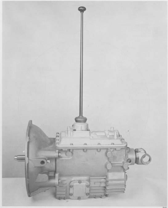
1 Service Manual Fuller Mid-Range Transmissions TRSM0160 October 2007 FS-5106A FS-6206A
2 Before starting a vehicle always be seated in the drivers seat, place the transmission in neutral, set the parking brakes and disengage the clutch. Before working on a vehicle place the transmission in neutral, set the parking brakes and block the wheels. Before towing the vehicle place the transmission in neutral, and lift the rear wheels off the ground or disconnect the driveline to avoid damage to the transmission during towing. cut 8007k1/ Eaton Corporation. All rights reserved.
3 TABLE OF CONTENTS FOREWORD MODEL DESIGNATIONS AND SPECIFICATIONS LUBRICATION OPERATION POWER FLOW TORQUE RECOMMENDATIONS PREVENTIVE MAINTENANCE PRECAUTIONS DISASSEMBLY INSPECTION REASSEMBLY DISASSEMBLY AND REASSEMBLY SHIFTING CONTROLS GEARSHIFT LEVER HOUSING ASSEMBLY SHIFT BAR HOUSING ASSEMBLY REMOVAL YOKE AN D CLUTCH HOUSING DISASSEMBLY TRANSMISSION REASSEMBLY TRANSMISSION INSTALLATION CLUTCH HOUSING AN D YOKE INSTALLATION SHIFTING CONTROLS SHIFT BAR HOUSING ASSEMBLY GEARSHIFT LEVER HOUSING ASSEMBLY
4 FOREWORD This manual is designed to provide detailed information necessary to service and repair the Transmission listed on the cover. As outlined in the Table of Contents, the manual is divided into 3 main sections: a. Technical information and reference b. Removal, disassembly, reassembly and installation c. Options The format of the manual is designed to be followed in its entirety if complete disassembly and reassembly of the transmission is necessary. But if only one component of the transmission needs to be repaired, refer to the Table of Contents for the page numbers showing that component. For example, if you need to work on the Shift Bar Housing, you will find instructions for removal, disassembly and reassembly on page 18. Instructions for installation are on page 53. Service Manuals, Illustrated Parts Lists, Drivers Instructions, and other forms of product service information for these and other Fuller Transmissions are available upon request. A Technical Literature Order Form may be found in the back of this manual. You may also obtain Service Bulletins, detailing information on product improvements, repair procedures and other service-related subjects by writing to the following address: EATON CORPORATION TRANSMISSION DIVISION Technical Service Department PO. Box 4013 Kalamazoo, Michigan (61 6) Every effort has been made to ensure the accuracy of all information in this brochure. However, Eaton Transmission Division makes no expressed or implied warranty or representation based on the enclosed information. Any errors or omissions may be reported to Training and Publications, Eaton Transmission Division, PO, Box 4013, Kalamazoo, Ml 49003,
5 MODEL DESIGNATIONS AND SPECIFICATIONS Specifications: IMPORTANT: All Fuller Transmissions are identified by model and serial number. This information is stamped on the transmission identification tag and affixed to the case. DO NOT REMOVE OR DESTROY THE TRANS- MISSION IDENTIFICATION TAG. Relative Speed Note 1 Note 2 Note 3 Gear Ratios PTO Gear to Length Weight 011 Capacity No Input R.P.M. In. Lbs. Pints Model Speeds 1st 2nd 3rd 4th 5th 6th Reverse Left Right (mm) (Kg ) (Liters) FS FS See Chart Notes (649) (162) (8.52) (649) (162) (8.52) CHART NOTES: 1. Lengths measured from face of clutch housing to center line of yoke. 2. Weights include shift bar housing and end yoke, less clutch housing, tower assembly and clutch release parts. For more information on available clutch housings, refer to publication FUL Clutch Housing Chart. All weights are approximate. 3. Oil capacities are approximate, depending on inclination of engine and transmission. Always fill transmission with proper grade and type of lubricant to level of filler opening. See LUBRICATION. /
6 LUBRICATION Proper Lubrication... the Key to long transmission life Proper lubrication procedures are the key to a good allaround maintenance program. If the oil is not doing its job, or if the oil level is ignored, all the maintenance procedures in the world are not going to keep the transmission running or assure long transmission life. Eaton Fuller Transmissions are designed so that the internal parts operate in a bath of oil circulated by the motion of gears and shafts. Thus, all parts will be amply lubricated if these procedures are closely followed: 1. Maintain oil level. Inspect regularly. 2. Change oil regularly. 3. Use the correct grade and type of oil. 4. Buy from a reputable dealer. Lubrication Change and Inspection I I I I Eaton Roadranger CD50 Transmission Fluid HIGHWAY USE Heavy Duty and Mid-Range First 3,000 to 5,000 miles Factory fill (4827 to 8045 Km) Initial drain, Every 10,000 miles Check fluid level. (16090 Km) Check for leaks. I Heavy Duty Highway Change Interval Every 250,000 miles Change transmission ( Km) fluid. Mid-Range Highway Change Interval Every 100,000 miles (160,000 Km) or every 3 years whichever occurs first. OFF-HIGHWAY USE Change transmission fluld. First 30 hours Factory fill initial drain, I Every 40 hours Inspect fluid level. Check for leaks. I Every 500 hours Change transmission fluld where severe dirt conditions exist. Every 1,000 hours Change transmission fluld (Normal off-highway use). Heavy Duty Engine Lubricant or Mineral Gear Lubricant HIGHWAY USE miles First 3,000 to 5,000 Factory fill (4827 to 8045 Km) initial drain. Every 10,000 miles Inspect lubricant level. (16090 Km) Check for leaks. I Every 50,000 miles Change transmission (80450 Km) lubricant. OFF-HIGHWAY USE First 30 hours Change transmission lubricant on new units. I Every 40 hours Inspect lubricant level. Check for leaks. I Every 500 hours Change transmission lubricant where severe dirt conditions exist. Every 1,000 hours Change transmission lubricant (Normal off-highway use). Change the oil filter when fluid or lubricant is changed. Recommended Lubricants Fahrenheit (Celsius) Grade Ambient Type (SAE) Temperature Eaton Roadranger CD50 Transmission Fluid 50 All Heavy Duty Engine 011 MIL-L-2104B, C or D or 50 Above 10 F(-12 C.) API-SF or API-CD 40 Above 10 F(-12 C.) (Previous API deslgnations 30 Below 10 F(-12 C) acceptable) Mineral Gear Oil with rust 90 Above 10 F(-12 C) and oxidation Inhibitor 80W Below 10 F(-12 C) API-GL-1 The use of mild EP gear oil or multi-purpose gear oil is not recommended, but if these gear oils are used, be sure to adhere to the following limitations: Do not use mild EP gear oil or multi-purpose gear oil when operating temperatures are above 230 F (110 C). Many of these gear oils, particularly 85W140, break down above 230 F and coat seals, bearings and gears with deposits that may cause premature failures. If these deposits are observed (especially a coating on seal areas causing oil leakage), change to Eaton Roadranger CD50 transmission fluid, heavy duty engine oil or mineral gear oil to assure maximum component life and to maintain your warranty with Eaton. (Also see Operating Temperatures.) Additives and friction modifiers are not recommended for use in Eaton Fuller transmissions. Proper Oil Level Make sure oil is level with filler opening. Because you can reach oil with your finger does not mean oil is at proper level. One inch of oil level is about one gallon of oil. Draining Oil Drain transmission while oil is warm. To drain oil remove the drain plug at bottom of case. Clean the drain plug before re-installing. Refilling Clean case around filler plug and remove plug from side of case. Fill transmission to the level of the filler opening. If transmission has two filler openings, fill to level of both openings. The exact amount of oil will depend on the transmission inclination and model. Do not over fill this will cause oil to be forced out of the transmission. When adding oil, types and brands of oil should not be mixed because of possible incompatibility.
7 LUBRICATION Operating Temperatures With Eaton Roadranger CD50 Transmission Fluid Heavy Duty Engine Oil and Mineral Oil The transmission should not be operated consistently at temperatures above 250 F (120 C). However, intermittent operating temperatures to 300 F (149 C) will not harm the transmission. Operating temperatures above 250 F increase the lubricant s rate of oxidation and shorten its effective life. When the average operating temperature is above 250 F, the transmission may require more frequent oil changes or external cooling. The following conditions in any combination can cause operating temperatures of over 250 F: (1) operating consistently at slow speeds, (2) high ambient temperatures, (3) restricted air flow around transmission, (4) exhaust system too close to transmission, (5) high horsepower, overdrive operation. External oil coolers are available to reduce operating temperatures when the above conditions are encountered. Transmission Oil Coolers are: Recommended With engines of 350 H.P. and above with overdrive transmissions Required With engines 399 H.P. and above with overdrive transmissions and GCW S over 90,000 lbs. With engines 399 H.P. and above and 1400 Lbs.-Ft. or greater torque With engines 450 H.P. and above Proper Lubrication Levels as Related to Transmission Installation Angles If the transmission operating angle is more than 12 degrees, improper lubrication can occur. The operating angle is the transmission mounting angle in the chassis plus the percent of upgrade (expressed in degrees). The chart below illustrates the safe percent of upgrade on which the transmission can be used with various chassis mounting angles. For example: if you have a 4 degree transmission mounting angle, then 8 degrees (or 14 percent of grade) is equal to the limit of 12 degrees. If you have a O degree mounting angle, the transmission can be operated on a 12 degree (21 percent) grade. Anytime the transmission operating angle of 12 degrees is exceeded for an extended period of time the transmission should be equipped with an oil pump or cooler kit to insure proper lubrication. Note on the chart the effect low oil levels can have on safe operating angles. Allowing the oil level to fall 1/2" below the filler plug hole reduces the degree of grade by approximately 3 degrees (5.5 percent). Proper Lubrication Levels are Essential! With EP or Multipurpose Gear Oil Mild EP gear oil and multipurpose gear oil are not recommended when lubricant operating temperatures are above 230 F (110 C). In addition, transmission oil coolers are not recommended with these gear oils since the oil cooler materials may be attacked by these gear oils. The lower temperature limit and oil cooler restriction with these gear oils generally limit their success to milder applications. Transmission Mounting Angle Dotted line showing 2 Quarts Low is for reference only. Not recommended. 5


8 OPERATION Gear Shift Lever Pattern and Shifting Instructions Follow the simple 6-speed shift pattern... General Information These transmissions have six forward speeds and one reverse, and are shifted as you would shift any synchronized manual transmission, following the simple 6-speed shift pattern. Driving Tips Ž Always use the clutch when making upshifts or downshifts. Premature synchronizer failure can result from not using the clutch. Always select a starting gear that will provide sufficient reduction for the load and terrain. Never downshift at too high of a road speed. Never slam or jerk the shift lever to complete gear engagement. Never coast with the transmission in neutral and the clutch dis-engaged.

9 POWER FLOW The transmission must efficiently transfer the engine's power, in terms of torque, to the vehicle's rear wheels. Knowledge of what takes place in the transmission during torque transfer is essential when trouble-shooting and making repairs becomes necessary. 1. Power (torque) from the engine is transferred to the input shaft and drive gear. 2. Torque is transferred to countershaft drive gear. 3. Torque is delivered along countershaft to all countershaft gears. 4. Torque is transferred to "engaged" mainshaft gear. The cross section illustrates 1st speed gear position. 5. Internal clutching teeth of engaged mainshaft gear transfers torque to mainshaft through synchronizer assembly. 6. Mainshaft transfers torque directly to driveshaft through rear yoke.
10 TORQUE RECOMMENDATIONS Correct torque application is important to assure long transmission life, Over or under tightening of fasteners can result in a loose installation and, in many instances, can eventually cause damage to the transmission. Use a torque wrench to obtain recommended torque ratings. Do not torque capscrews dry.
11 TORQUE RECOMMENDATIONS
12 PREVENTIVE MAINTENANCE
13 PREVENTIVE MAINTENANCE PREVENTIVE MAINTENANCE CHECK CHART CHECKS WITHOUT PARTIAL DISASSEMBLY OF CHASSIS OR CAB Clutch Housing Mounting a. Check all capscrews of clutch housing flange for looseness. Clutch Release Bearing (Not Shown) a. Remove hand hole cover and check radial and axial clearance in release bearing. b. Check relative position of thrust surface of release bearing with thrust sleeve on pushtype clutches. Clutch Pedal Shaft and Bores a. Pry upward on shafts to check wear. b. If excessive movement is found, remove clutch release mechanism and check bushings in bores and wear on shafts. 8. Gear Shift Lever Housing Assembly a. Remove the gear shift lever housing assembly from transmission. b. Check tension spring and washer for set and wear. c. Check bottom end of gear shift lever for wear of slots. Also check for wear of finger assembly. CHECKS WITH DRIVE LINE DROPPED 9. Universal Joint Companion Flange or Yoke Nut a. Check for tightness. Tighten to recommended torque. 10. Output Shaft (Not Shown) a. Pry upward against output shaft to check radial clearance in mainshaft rear bearing Lubricant a. Change at specified service intervals. b. Use only the types and grades as recommended. See LUBRICATION. Filler and Drain Plugs a. Remove filler plug and check level of lubricant at specified intervals. Tighten filler and drain plugs securely. Capscrews and Gaskets a. Check all capscrews, especially those on PTO covers and rear bearing covers for looseness which would cause oil leakage. See TORQUE RECOMMENDATIONS. b. Check PTO opening and rear bearing covers for oil leakage due to faulty gasket. Gear Shift Lever a. Check for looseness and free play in housing. If lever is loose in housing, proceed with Check No. 8. CHECKS WITH UNIVERSAL JOINT COMPANION FLANGE OR YOKE REMOVED NOTE: If necessary, use solvent and shop rag to clean sealing surface of companion flange or yoke. DO NOT USE CROCUS CLOTH, EMERY PAPER OR OTHER ABRASIVE MATERIALS THAT WILL MAR SURFACE FINISH Splines on Output Shaft (Not Shown) a. Check for wear from movement and chucking action of the universal joint companion flange or yoke. Mainshaft Rear Bearing Cover a. Check oil seal for wear.
14 PRECAUTIONS Disassembly It is assumed in the detailed assembly instructions that the lubricant has been drained from transmission, the necessary linkage disconnected and the transmission has been removed from vehicle chassis. Removal of the gear shift lever housing assembly is included in the detailed instructions (Disassembly and Reassembly Shifting Controls); however, this assembly must be detached from shift bar housing before transmission can be removed. FOLLOW CLOSELY EACH PROCEDURE IN THE DETAILED INSTRUCTIONS. / MAKING USE OF THE TEXT., ILLUSTRATIONS AND PHOTOGRAPHS PROVIDED. 1. BEARINGS Carefully wash and relubricate all reusable bearings as removed and protectively wrap until ready for use. Remove bearings planned to be reused with pullers designed for this purpose. 2. ASSEMBLIES When disassembling the various assemblies, such as the mainshaft, countershafts, and shift bar housing, lay all parts on a clean bench in the same sequence as removed. This procedure will simplify reassembly and reduce the possibility of losing parts. 3. SNAP RINGS Remove snap rings with pliers designed for this purpose. Snap rings removed in this manner can be reused, if they are not sprung or loose. 4. CLEANLINESS Provide a clean place to work. It is important that no dirt or foreign material enters the unit during repairs. Dirt is an abrasive and can damage bearings. It is always good practice to clean the outside of the unit before starting the planned disassembly. 5. WHEN USING TOOLS TO MOVE PARTS Always apply force to shafts, housings, etc, with restraint. Movement of some parts is restricted. Never apply force to the part being driven after it stops solidly. The use of soft hammers, bars and mauls for all disassembly work is recommended. Inspection Before reassembling the transmission, check each part carefully for abnormal or excessive wear and damage to determine reuse or replacement. When replacement is necessary, use only genuine Fuller Transmission parts to assure continued performance and extended life from your unit. Since the cost of a new part is generally a small fraction of the total cost of downtime and labor, avoid reusing a questionable part which could lead to additional repairs and expense soon after initial reassembly. To aid in determining the reuse or replacement of any transmission part, consideration should also be given to the unit s history, mileage, application, etc. Recommended inspection procedures are provided in the following checklist. A. BEARINGS B. GEARS 1. Wash all bearings in clean solvent. Check 1. balls, rollers and raceways for pitting, discoloration, and spalled areas. Replace bearings that are pitted, discolored, spalled, or damaged during disassembly. 2. Lubricate bearings that are not pitted, discolored, or spalled and check for axial and radial clearances. Replace bearings with excessive clearances Check bearing fits. Bearing inner races should be tight to shaft; outer races slightly tight to slightly loose in case bore. If bearing spins freely in bore, however, case should be replaced. Check gear teeth for frosting and pitting. Frosting of gear tooth faces present no threat of transmission failure. Often in continued operation of the unit, frosted gears will heal and not progress to the pitting stage. In most cases, gears with light to moderate pitted teeth have considerable gear life remaining and can be reused, but gears with advanced stage pitting should be replaced. Check for gears with clutching teeth abnormally worn, tapered, or reduced in length from clashing in shifting. Replace gears found in any of these conditions.
15 PRECAUTIONS Inspection (cont d.) c. D. E. F. G. H. 3. Check axial clearance of gears. Where excessive clearance is found, check gear snap ring, split washer, clutch hub, and gear hub for excessive wear. SPLINES 1. Check splines on all shafts for abnormal wear. If sliding clutch gears, companion flange, or clutch hub have worn into the sides of the splines, replace the specific shaft affected. SPLIT WASHERS 1. Check surfaces of all washers. Washers scored or reduced in thickness should be replaced. REVERSE IDLER GEAR ASSEMBLIES 1. Check for excessive wear from action of roller bearings. GRAY IRON PARTS 1. Check all gray iron parts for cracks and breaks. Replace or repair parts found to be damaged. Heavy castings may be welded or brazed provided the cracks do not extend into bearing bores or bolting surfaces. When welding, however, never place the ground so as to allow current to pass through the transmission. CLUTCH RELEASE PARTS 1. Check clutch release parts. Replace yokes worn at cam surfaces and bearing carrier worn at contact pads. 2. Check pedal shafts. Replace those worn at bushing surfaces. SHIFT BAR HOUSING ASSEMBLY 1. Check for wear on shift yokes and finger assembly at pads and lever slot. Replace excessively worn parts. 2. Check yokes for correct alignment. Replace sprung yokes. 3. Check Iockscrews in yoke assembly retainer plates. Tighten those found loose. 1. GEAR SHIFT LEVER HOUSING ASSEMBLY 1. Check spring tension on shift lever. Replace tension spring if lever moves too freely. 2. If housing is disassembled, check bottom end of gear shift lever and shift finger assembly for wear. Replace both parts if excessively worn. J. BEARING COVERS 1. Check covers for wear from thrust of adjacent bearing. Replace covers damaged from thrust of bearing outer race. 2. Check bores of covers for wear. Replace those worn oversize. K. OIL SEALS 1. Check oil seal in input shaft and rear bearing cover. If sealing action of lip has been destroyed, replace seai. L. CLUTCHING TEETH 1. Check all shift yokes and yoke slots in sliding clutches for extreme wear or discoloration from heat. 2. Check engaging teeth of sliding clutches for partial engagement pattern. M. SYNCHRONIZER ASSEMBLY 1. Check synchronizer for burrs, uneven and excessive wear at contact surface, and metal particles. 2. Check blocker pins for excessive wear or looseness. 3. Check synchronizer contact surfaces on the synchronizer cups for wear.
16 PRECAUTIONS Reassembly Make sure that interiors of case and housings are clean. It is important that dirt and other foreign materials be kept out of the transmission during reassembly. Dirt is an abrasive and can damage polished surfaces of bearings and washers. Use certain precautions, as listed below, during reassembly. 1. GASKETS Use new gaskets throughout the 5. INITIAL LUBRICATION Coat all thrust washers, transmission as it is being rebuilt. Make sure all gaskets are installed. An omission of any gasket can result in oil leakage or misalignment of synchronizers, and bearings with transmission lubricant during reassembly to prevent damage during initial start up. bearing covers. Install PTO and shift bar housing 6. END PLAY Maintain end play on countershaft and mainshaft assemblies. gaskets dry. 2. CAPSCREWS TO prevent oil leakage and loosening, use Loctite 262 thread sealant on all captacts the inner race of the bearing is recom- 7. BEARINGS Use of a sleeve type driver that conscrews. For torque ratings, see TORQUE mended to prevent damage to the rollers and RECOMMENDATIONS. cage. 3. SHIMS Apply a light coat of Loctite 510 to both 8. UNIVERSAL JOINT COMPANION FLANGE OR sides of shims before final installation to prevent YOKE Pull the companion flange or yoke into leakage. place with the output shaft nut, using ASSEMBLY Refer to the illustrations provided in the detailed disassembly instructions as a guide to reassembly. foot-pounds ( N.m) of torque. Make sure the speedometer drive gear or a replacement spacer has been installed. Failure to properly torque the nut can result in damage to the mainshaft rear bearing. IMPORTANT: REFER TO THE APPROPRIATE ILLUSTRATED PARTS LIST (SPECl- FIED BY MODEL SERIES) TO ENSURE THAT PROPER PARTS ARE USED DURING REASSEMBLY OF THE TRANSMISSION.


17 DISASSEMBLY AND REASSEMBLY SHIFTING CONTROLS GEARSHIFT LEVER HOUSING ASSEMBLY A. Removal and Disassembly 1. Turn out four capscrews and remove tower assembly and gasket from shift bar housing. 2. Remove shift lever grip and boot from shift lever, secure assembly in vise with bottom of housing up. Use a large screwdriver to twist between spring and housing, forcing spring from under lugs in housing. Do one coil at a time.
 3.")


18 DISASSEMBLY AND REASSEMBLY SHIFTING CONTROLS GEARSHIFT LEVER HOUSING ASSEMBLY (con't.) 3. Remove tension spring, washer and gearshift lever from housing. 4. Remove spade pins from bore in housing B. Reassembly of Gearshift Lever Housing Assembly Position gearshift lever in housing with spade pins in lever ball slot and install tension spring washer over ball, dished side up. 1. With gearshift lever housing secured in vise as during disassembly, install spade pins in bore of housing.
 3.")

19 DISASSEMBLY AND REASSEMBLY SHIFTING CONTROLS GEARSHIFT LEVER HOUSING ASSEMBLY (con't.) 3. Install tension spring under lugs in housing, seating one coil at a time. Use of a spring driving tool is recommended. 4. Remove assembly from vise and install rubber boot over gearshift lever and against housing. Install shift lever grip.
20 DISASSEMBLY AND REASSEMBLY SHIFTING CONTROLS SHIFT BAR HOUSING ASSEMBLY Cut / 86 Cut 6226A-586
 A. Removal and Disassembly 1.")


21 DISASSEMBLY AND REASSEMBLY SHIFTING CONTROLS SHIFT BAR HOUSING ASSEMBLY (con't.) A. Removal and Disassembly 1. Shift transmission into neutral position, turn out capscrews, and lift shift bar housing and gasket from case Remove reverse yoke assembly Lay shift bar housing on workbench as shown. Slide 4. 5th-6th yoke into 5th position and remove capscrews and retainers. Remove 1st-2nd yoke assembly and interlock pin
 5. Remove 3rd-4th yoke assembly and interlock pin. 7.")


22 DISASSEMBLY AND REASSEMBLY SHIFTING CONTROLS SHIFT BAR HOUSING ASSEMBLY (con't.) 5. Remove 3rd-4th yoke assembly and interlock pin. 7. Remove interlock balls, detent balls, and springs. 6. Remove 5th-6th yoke. NOTE: If yoke replacement is required, yoke can be removed by driving the roll pin through the yoke and rail. If the yoke pad inserts are to be replaced, remove worn pad from shift fork, install new pad, and bend tabs over top and bottom of fork.
 Cut 7226-8/86 I B.")


23 DISASSEMBLY AND REASSEMBLY SHIFTING CONTROLS SHIFT BAR HOUSING ASSEMBLY (con't.) Cut /86 I B. Disassembly of Reverse Plunger 1. Depress reverse plunger springs and retainer as shown. Remove snap ring and spring retainer. SNAP RING AND RETAINER ARE UNDER SPRING PRESSURE. 2. Remove reverse plunger springs. NOTE: Some assemblies may only use two springs. Remove washer and plunger (inset).


24 DISASSEMBLY AND REASSEMBLY SHIFTING CONTROLS SHIFT BAR HOUSING ASSEMBLY (coní t.) C. Reassembly of Reverse Plunger Assembly Depress reverse plunger retainer and springs and install snap ring in groove of shift block Install plunger and washer as shown and install reverse plunger springs (inset). D. Reassembly of Shift Bar Housing Cut 7226A-8/86 1. Install interlock balls, detent balls and springs in install 3rd and 4th detent spring and ball. Position the following sequence; position (3) balls in the re- (2) balls in adjacent cross bore and install 5th and verse light switch bore and install reverse detent 6th detent spring and ball. spring and ball. Position (2) balls in adjacent cross NOTE: Balls and springs can be used interchanbore and install 1st and 2nd detent spring and geably. ball. Position (2) balls in adjacent cross bore and


25 DISASSEMBLY AND REASSEMBLY SHIFTING CONTROLS SHIFT BAR HOUSING ASSEMBLY (conõt.) NOTE: All yoke assemblies must be installed in the neutral position Position reverse yoke in housing assembly as shown. 4. Install interlock pin in 3rd-4th yoke assembly and position as shown Install interlock pin in 1st-2nd yoke assembly and position as shown Position 5th-6th yoke assembly in housing as shown.
 NOTE: The shift yoke retainer capscrew holes are not tapped on new shift bar housing.")


26 DISASSEMBLY AND REASSEMBLY SHIFTING CONTROLS SHIFT BAR HOUSING ASSEMBLY (con't.) NOTE: The shift yoke retainer capscrew holes are not tapped on new shift bar housing. The capscrews that are used are "thread forming" and can be reused if the shift bar housing is replaced Position shift yokes as shown. Install front retainer over shift rails and install front (2) capscrews. NOTE: It may be necessary to support rails in proper position while installing rail supports Position rear retainer over shift rails and install capscrews Position shift yokes as shown and install center retainer and capscrews Slide 5th-6th shift yoke into 5th position (inset) and install remaining 2 capscrews. Return 5th-6th yoke to neutral position. Tighten all retainer capscrews to Ibs.-ft. (27-34 N.m).

.")

27 REMOVAL - YOKE AND CLUTCH HOUSING A. Removal of Yoke 1. Lock the transmission by engaging two mainshaft gears (inset). use a large breaker bar to turn the nut from the output shaft. 2. Remove yoke from output shaft


28 REMOVAL - YOKE AND CLUTCH HOUSING B. Removal of Clutch Housing 1. Remove four retaining bolts as shown Jar clutch housing with rubber mallet and pull from transmission case.


29 DISASSEMBLY - TRANSMISSION A. Removal & Disassembly of Input Shaft Assembly Cut / Remove input shaft assembly from transmission Turn out six capscrews, jar front bearing cover with a rubber mallet and remove. If necessary remove oil seal from cover (inset) Using a chisel, remove bearing cage and rollers. install bearing puller and remove bearing race from input shaft.


30 DISASSEMBLY - TRANSMISSION B. Removal & Disassembly of Mainshaft Turn out four retaining nuts and lockwashers. Us- 2. Remove shims and speedometer drive gear or roing screwdrivers in notches, remove rear bearing tor. cover. If necessary remove oil seal from cover (in- NOTE: Shims may come off with rear bearing set) cover.
.")


31 DISASSEMBLY - TRANSMISSION 3. Wrap sling around the 3rd-4th synchronizer (inset). Use hoist to remove mainshaft assembly from case Remove snap ring from front of mainshaft front bearing (inset). Using a puller mounted behind 5th-6th shift hub, remove hub and bearing. 4. Install mainshaft assembly in vise equipped with soft jaws or wood, front of shaft facing up. Remove 5th- 6th speed synchronizer and cups. 6. Remove 5th gear and bearings from mainshaft
,")


32 DISASSEMBLY - TRANSMISSION 7. Remove snap ring (inset), thrust washer, and locat- 9. Remove 4th speed synchronizer cup and 3rd-4th ing ball. speed synchronizer 8. Remove 4th gear and bearings.
 and")
,")


33 DISASSEMBLY - TRANSMISSION 10. Remove snap ring (inset) and 3rd-4th shift hub. 12. Remove snap ring (inset), thrust washer and locating ball. 11. Remove 3rd gear and bearings from mainshaft. 13. Remove 2nd gear and bearings from mainshaft.


34 DISASSEMBLY - TRANSMISSION 14. Remove 1st-2nd speed synchronizer. 16. Using a puller (inset), remove reverse gear, spacer, and rear bearing Reposition mainshaft in vise, rear of shaft facing up. Remove reverse sliding clutch gear bearings and reverse gear
 or press remove 1st")

35 DISASSEMBLY - TRANSMISSION 18. Using a puller (inset) or press remove 1st gear, 19. Remove first gear bearing and spacer. clutch hub, and reverse gear bearing race from mainshaft.


.")
36 DISASSEMBLY - TRANSMISSION C. Removal and Disassembly of Countershaft and Reverse Idler 1. Turn out four capscrews, remove countershaft rear bearing cover and gasket. 2. Turn out two set screws (inset). Remove bearing retainer, outer race, and shims (inset). NOTE: Countershaft may slide to the rear and out of bearing bore.


37 DISASSEMBLY - TRANSMISSION 3. Using a slide hammer remove reverse idler shaft. Remove locating ball once it is exposed (inset). 5. Move countershaft assembly to the rear and lift it from the case. 4. Remove reverse idler, bearings, spacer and thrust washers, 6. If countershaft front bearing race is to be replaced, drive bore plug through front of transmission and drive the race to the rear toward the inside of the case.


38 DISASSEMBLY - TRANSMISSION 7. Position puller jaws behind rear countershaft bearing and remove bearing. 9. Remove drive gear retaining snap ring from front of shaft. 8. Position countershaft in vise, front of shaft facing up. Position puller jaws into notches behind front countershaft bearing and remove bearing. 10. Use the rear face of the drive gear as a base, then press it from the countershaft as shown. Remove drive gear locating key from shaft (inset).


39 DISASSEMBLY - TRANSMISSION 11. Using the rear face of 5th speed gear as a base, press it from the countershaft. Remove 5th gear key from shaft (inset) Using the rear face of 3rd speed gear as a base, press it from the countershaft Using the rear face of 4th speed gear as a base, press it from the countershaft. NOTE: Be sure that 5th and 6th speed gear keys have been removed before removing 4th gear from countershaft.


40 REASSEMBLY - TRANSMISSION A. Reassembly and Installation of Countershaft and Reverse Idler 1. Press 3rd gear on countershaft as shown, splined 3. Install 5th and 6th speed gear keys on counend of gear hub to front of shaft. tershaft (inset). Align keyway of 5th speed gear to key on shaft. Press 5th gear on, long hub of gear to front of shaft. 2. Press 4th speed gear on countershaft, long hub of 4. Align keyway of drive gear to key on countershaft. gear to rear of shaft. Press drive gear on, long hub of gear to rear of shaft.


41 REASSEMBLY - TRANSMISSION 5. Install snap ring in groove at front of coun- 7. Install rear countershaft bearing as shown. tershaft. 8. If previously removed, install snap ring, countershaft front bearing race (from inside of case) and bore plug. Coat outer diameter of bore plug with Loctite #510 before installing. 6. Install front countershaft bearing as shown.


42 REASSEMBLY - TRANSMISSION 9. Carefully lower countershaft into case Use grease on reverse idler thrust washers to hold in place. Position tangs of washers in groove of housing. 10. Turn transmission tion countershaft race. case on end as shown. Posiassembly into front bearing
 and position")


.")
43 REASSEMBLY - TRANSMISSION 12. Install bearings and spacer in reverse idler gear (inset) and position gear in housing with long hub of gear toward the front. 14. Install countershaft rear bearing race into case as shown. 13. Insert idler shaft through case and idler gear bearings. Line up notch in shaft with notch in case, install lock ball, and drive shaft into position (inset). 14. Temporarily install new shims into bearing retainer (inset). Install retainer. Tighten set screws to 5-10 lbs. ft. (7-14 Nm). NOTE: Lube hole in retainer must line up with lub hole in case.


44 REASSEMBLY - TRANSMISSION B. Reassembly and Installation of Mainshaft 1. Install manshaft in vise equipped with wood or brass jaws, rear of mainshaft facing up. Lubricate and install first gear bearings with spacer between bearings as shown. 3. Install reverse gear clutch hub with notched teeth facing down. 2. Install mainshaft 1st gear, clutching teeth of gear facing down Using heat lamp or hot plate and oil, heat reverse gear bearing race and install on shaft with notched end facing down. Race can also be installed using a sleeve type driver. NOTE: Do not heat reverse bearing race over 320 o F (160 o C).


45 REASSEMBLY - TRANSMISSION 5. Install reverse gear sliding clutch with stepped shoulder down Install reverse gear with clutching teeth facing down Lubricate and install reverse gear bearings on race Install reverse gear washer. Washer can be installed either way.


46 REASSEMBLY - TRANSMISSION Using a sleeve type driver install rear mainshaft bearing as shown. 11. Lubricate and install 2nd gear bearings (inset). Install 2nd gear, clutching teeth facing down. 45-1o Reposition mainshaft in vise with front of mainshaft facing up. Lubricate friction surface with transmission lube and install 1st-2nd speed synchronizer E Install locating ball and washer. Washer can be installed either way. Install snap ring as shown (inset).
.")


. 16.")
47 REASSEMBLY - TRANSMISSION Lubricate and install 3rd gear bearings (inset). install 3rd gear, clutching teeth facing up Lubricate friction surface with transmission lube and install 3rd-4th speed synchronizer and 4th speed synchronizer cup. 14. Install 3rd-4th clutch hub with stepped face of hub facing up. Install snap ring in groove of mainshaft (inset). 16. Lubricate and install 4th gear bearings (inset). lnstall 4th gear, clutching teeth facing down.

. 19.")
.")
.")
48 REASSEMBLY - TRANSMISSION 17. Install locating ball and washer. Washer can be installed either way. Install snap ring as shown (inset). 19. Install 5th-6th clutch hub with flat surface facing up Lubricate and install 5th gear bearings (inset). install 5th gear, clutching teeth facing up. 20. Install 5th speed synchronizer cup (inset). Lubricate friction surface with transmission lube and install 5th-6th speed synchronizer assembly and 6th speed synchronizer cup.


49 REASSEMBLY - TRANSMISSION 23. Using a sling around the 3rd-4th synchronizer carefully lower mainshaft into case. 21. Using a sleeve type driver install front bearing. Install snap ring in groove shaft (inset). mainshaft on end of 22. Remove mainshaft assembly from vise and place on bench. Shift synchronizer into 4th gear Using a sleeve type driver install bearing on input shaft.


 49-28 28.")

50 REASSEMBLY - TRANSMISSION Install input shaft by aligning clutching teeth on main drive gear with teeth in 5th speed synchronizer cup. 27. Install input shaft bearing cover and gasket. Apply Loctite 262 to threads of capscrews and torque to lbs. ft. (20-27 Nm) Install speedometer drive gear or rotor on output shaft. 26. Coat outer diameter of input shaft bearing cover oil seal with Loctite 510. Install seal with flanged driver as shown. Install input shaft bearing race (inset).
. Add shims for more end play and remove shims for less end play.")

51 REASSEMBLY - TRANSMISSION 16. Rotate countershaft to seat bearings and races. Position dial indicator as shown, lift countershaft to measure end play. End play must be set at ( mm). Add shims for more end play and remove shims for less end play. NOTE: Once end play is correct remove retainer and apply a light coat of Loctite 510 to both sides of shims and face of retainer. Coat threads of set screws with Loctite 262 and retorque. 17. Install countershaft rear bearing cover and gasket. Coat threads of capscrews with Loctite 262 and torque to lbs. ft. (27-41 Nm). Tip transmission to horizontal position to install mainshaft.
.")


52 REASSEMBLY - TRANSMISSION 29. If necessary install rear bearing race (inset). Temporarily install shims and rear bearing cover. Tighten nuts to lbs. ft. (81-95 Nm). NOTE: Top of rear bearing cover is marked for proper installation. 31. Position dial indicator as shown. Pry up on output shaft to measure end play. End play must be set at ( mm rein). Add shims for more end play, remove shims for less end play. NOTE: Once end play is correct remove yoke and rear bearing cover and apply a light coat of Loctite 510 to both sides of shims. 30. Place transmission in a vertical position as shown. Install yoke and nut. Torque yoke nut to lbs. ft. ( Nm). Rotate input shaft and mainshaft to seat bearings and races. 32. Install rear seal using a flanged driver.
.")
53 REASSEMBLY - TRANSMISSION 33. Install rear bearing cover. Tighten nuts to lbs. ft. (81-95 Nm). Top of rear bearing cover is marked for proper installation.
. B.")
.")
54 INSTALLATION-CLUTCH HOUSING AND YOKE A. Installation of Clutch Housing 1. Position clutch housing on Install four retaining bolts lbs. ft. ( Nm). B. Installation of Yoke 52A-01 front of transmission. and torque to Lock the transmission by engaging two mainshaft gears (inset). Carefully install yoke and nut. Tighten nut to lbs. ft ( Nm).
 and install gasket on case.")


55 INSTALLATION-SHIFTING CONTROLS A. Shift Bar Housing Assembly 1. Place transmission in neutral (inset) and install gasket on case. Place shift bar housing in neutral and install on case making sure shift yokes align with corresponding synchronizers and sliding clutch Apply Loctite 262 to threads of capscrews. Install capscrews into housing and torque to lbs. ft (27-34 Nm). 2. Apply Loctite 262 to threads and install two shift bar housing capscrews in allignment holes as shown. Install front capscrew first then rear.


56 INSTALLATION-SHIFTING CONTROLS B. Gear Shift Lever Housing Assembly With the shift bar housing in the neutral position, install gasket and gear shift lever assembly on the shift bar housing. Fit gear shift lever in corresponding finger assembly in bar housing as lever is installed. 2. Coat threads of retaining capscrews with Loctite 262 and install. Torque capscrews to lbs. ft. (27-34 Nm).
57
58 Copyright Eaton Corporation, Eaton hereby grant their customers, vendors, or distributors permission to freely copy, reproduce and/or distribute this document in printed format. It may be copied only in its entirety without any changes or modifications. THIS INFORMATION IS NOT INTENDED FOR SALE OR RESALE, AND THIS NOTICE MUST REMAIN ON ALL COPIES. Note: Features and specifications listed in this document are subject to change without notice and represent the maximum capabilities of the software and products with all options installed. Although every attempt has been made to ensure the accuracy of information contained within, Eaton makes no representation about the completeness, correctness or accuracy and assumes no responsibility for any errors or omissions. Features and functionality may vary depending on selected options. For spec ing or service assistance, call HELP (4357) or visit In Mexico, call Roadranger: Eaton and trusted partners providing the best products and services in the industry, ensuring more time on the road. Eaton Corporation Vehicle Group P.O. Box 4013 Kalamazoo, MI USA HELP (4357) Printed in USA
Fuller Mid-Range Transmissions TRDR0100
 Driver Instructions Video Instruction Available Instructional videos are available for download at no charge at roadranger.com Videos are also available for purchase. To order, call 1-888-386-4636. Ask
For the most current information, visit the Roadranger web site at
 Eaton Fuller Heavy Duty Transmissions 8 - Speed Direct Drivers Instructions TRDR-0310 March 2004 For the most current information, visit the Roadranger web site at www.roadranger.com Warnings Warnings
Service Manual. Fuller Mechanical Transmissions TRSM0992 October 2007
 Service Manual Fuller Mechanical Transmissions TRSM0992 October 2007 Introduction Warnings and Precautions Before starting a vehicle always be seated in the driver s seat, place the transmission in neutral,
Service Manual. Fuller Heavy Duty Transmissions TRSM0250 October 2007
 Service Manual Fuller Heavy Duty Transmissions TRSM0250 October 2007 TABLE OF CONTENTS FOREWORD........................................ MODEL DESIGNATIONS AND SPECIFICATIONS.......... LUBRICATION......................................
Eaton Fuller Heavy Duty Transmissions
 Eaton Fuller Heavy Duty Transmissions 13 Speed Models Driver Instructions TRDR-0630 May 2004 For the most current information, visit the Roadranger web site at www.roadranger.com General Information Warnings
Eaton 9-Speed Synchronized Transmissions Single H Shift Control Configuration TRDR0072
 Driver Instructions Eaton 9-Speed Synchronized Transmissions Single H Shift Control Configuration TRDR0072 February 2008 FS(O) 6109 FS(O) 6209 FS(O) 6309 FS(O) 8209 FS(O) 8309 FS(O) 10209 FS(O) 10309 Warnings
Service Manual. Fuller Medium Heavy Transmissions TRSM0201 October 2007
 Service Manual Fuller Medium Heavy Transmissions TRSM0201 October 2007 Model Designations...2 Description...3 Specifications...4 Lubrication...5 Conversion to Overdrive...6 Clutch Shaft Replacement...6
Eaton Fuller Advantage Heavy-Duty Manual Transmissions TRDR0970 EN-US
 Driver Instructions Video Instruction Available Instructional videos are available for download at no charge at Roadranger.com Videos are also available for purchase. To order, call 1-888-386-4636. Ask
Service Manual. Fuller Heavy Duty Transmissions TRSM0515 October 2007
 Service Manual Fuller Heavy Duty Transmissions TRSM0515 October 2007 TABLE OF CONTENTS Timing Description Operations Lubrication Preventive Maintenance Torque Recommendations Air System Precautions Disassembly
Service Manual. Fuller Heavy Duty Transmissions. Fuller Heavy Duty Transmissions. October 2007 TRSM0300. More time on the road
 Fuller Heavy Duty Transmissions More time on the road Service Manual Fuller Heavy Duty Transmissions TRSM0300 October 2007 RTO-11607L RTO-11607L RTO-11607LL RTO-11607LL RTOF-11607L RTOF-11607LL TABLE
Service Manual. Fuller Heavy Duty Transmissions TRSM0880 October 2007
 Service Manual Fuller Heavy Duty Transmissions TRSM0880 October 2007 For parts or service call us Pro Gear & Transmission, Inc. 1 (877) 776-4600 (407) 872-1901 parts@eprogear.com 906 W. Gore St. Orlando,
Fuller Heavy Duty Transmissions TRSM0660 October 2007
 Service Manual Fuller Heavy Duty Transmissions TRSM0660 October 2007 RTLO-14613B RTLOF-14613B TABLE OF CONTENTS FOREWORD............. MODEL DESIGNATIONS AND LUBRICATION............ OPERATION.............
Fuller Heavy Duty Transmissions. Video Instruction Available. Fuller Heavy Duty Transmissions TRDR3349 September 2007
 Fuller Heavy Duty Transmissions More time on the road Video Instruction Available Instructional videos are available for download at no charge at roadranger.com Videos are also available in DVD format
Fuller Heavy Duty Transmissions TRSM0503 October 2007
 Service Manual Fuller Heavy Duty Transmissions TRSM0503 October 2007 RTX-12510 RTX-12515 RTXF-12510 RTXF-12515 Table of Contents Model Designations..............................3 Description....................................4
Eaton Fuller Heavy-Duty Transmissions TRDR0670 EN-US
 Driver Instructions Video Instruction Available Instructional videos are available for download at no charge at roadranger.com Videos are also available for purchase. To order, call 1-888-386-4636. Ask
MANUAL TRANS OVERHAUL - BORG-WARNER - T56 6-SPEED MANUAL TRANSMISSIONS Borg-Warner T56 (MM6) 6-Speed
 6-Speed") IDENTIFICATION MANUAL TRANS OVERHAUL - BORG-WARNER - T56 6-SPEED 1998 MANUAL TRANSMISSIONS Borg-Warner T56 (MM6) 6-Speed Transmission has 2 identification labels, located on lower left side of case. One
IDENTIFICATION MANUAL TRANS OVERHAUL - BORG-WARNER - T56 6-SPEED 1998 MANUAL TRANSMISSIONS Borg-Warner T56 (MM6) 6-Speed Transmission has 2 identification labels, located on lower left side of case. One
Service Manual. Fuller Heavy Duty Transmissions
 Fuller Heavy Duty Transmissions More time on the road Service Manual Fuller Heavy Duty Transmissions TRSM0430 July 2010 RT-8608L RTF-8608L RTO-11608LL RTO-14608LL RTOF-11608LL RTOF-14608LL RTX-11608LL
Transmission Overhaul Procedures-Bench Service
 How to Assemble the Lower Reverse Idler Gear Assembly Special Instructions In 1996 Eaton changed the reverse idler system design. In the nut design, the reverse idler bearing was lubricated through a hole
Service Manual. Fuller Mid Range Transmissions TRSM0195 October 2007
 Service Manual Fuller Mid Range Transmissions TRSM0195 October 2007 Caution - Before towing the vehicle, be sure to lift the rear wheels off the ground or disconnect the driveline to avoid damage to the
Fuller Automated Transmissions TRDR2500
 Driver Instructions Fuller Automated Transmissions TRDR2500 July 2007 RTO-10910B-DM2 RTO-12910B-DM2 RTO-14910B-DM2 RTO-16910B-DM2 Warnings & Cautions Warnings & Cautions WARNING Read the entire driver
Fuller Heavy-Duty Transmissions TRSM1500 EN-US May 2017
 Service Manual Fuller Heavy-Duty Transmissions TRSM1500 EN-US May 2017 RT-8908LL RTO-11707LL RTO-11708LL RTOF-11707LL RTOF-11708LL RTOF-14708LL RTX-11708LL RTX-14708LL RTXF-11708LL RTXF-14708LL RTO-11707DLL
Fuller Automated Transmissions TRSM0020 October 2007
 Service Manual Fuller Automated Transmissions TRSM000 October 007 RT-09A-AT RT-09A-ATR RT-09A-ATS RT-09A-AT RT-409A-ATS RTO-09A-AT RTO-09A-ATS RTO-09B-AT RTO-09B-ATE RTO-09B-ATR RTO-09B-ATS RTO-09A-AT
Fuller Automated Transmissions TRDR0082
 Driver Instructions Video Instruction Available Instructional videos are available for download at no charge at roadranger.com Videos are also available for purchase. To order, call 1-888-386-4636. Ask
Fuller Heavy Duty Transmissions. More time on the road. Service Manual. Fuller Heavy Duty Transmissions TRSM0917
 Fuller Heavy Duty Transmissions More time on the road Service Manual Fuller Heavy Duty Transmissions TRSM0917 October 2007 Table of Contents Applications Why Oil Cooling...................... 1 Why Operating
Eaton Fuller Advantage Heavy-Duty Manual Transmissions TRSM0970 EN-US
 Service Manual Eaton Fuller Advantage Heavy-Duty Manual Transmissions TRSM0970 EN-US January 2016 FA(F)-9810B FA(F)-11810B FA(F)-12810B FA(F)-13810B FA(F)-14810B FA(F)-15810B FAO(F)-11810C FAO(F)-12810C
Service Manual. Fuller Mid Range Transmissions TRSM0197 October 2007
 Service Manual Fuller Mid Range Transmissions TRSM0197 October 2007 Caution - Before towing the vehicle, be sure to lift the rear wheels off the ground or disconnect the driveline to avoid damage to the
Driver Instructions. Fuller Heavy Duty Transmissions. Video Instruction Available. Fuller Heavy Duty Transmissions TRDR0550 September 2007
 Fuller Heavy Duty Transmissions More time on the road Video Instruction Available Instructional videos are available for download at no charge at roadranger.com Videos are also available in DVD format
Transmission Overhaul Procedures-Bench Service
 How to Install the Auxiliary Countershaft Assembly Special Instructions To make auxiliary section assembly easier, you can make an auxiliary section fixture out of a 2" x 12" piece of wood. 3' 1' 3" 4.56"
TRANSMISSION AND TRANSFER CASE
 DR TRANSMISSION AND TRANSFER CASE 21-1 TRANSMISSION AND TRANSFER CASE TABLE OF CONTENTS page MANUAL TRANSMISSION- G56- SERVICE INFORMATION...1 MANUAL TRANSMISSION- GETRAG 238- SERVICEINFORMATION...69 MANUAL
TRANSMISSION AND TRANSFER CASE
 TJ TRANSMISSION AND TRANSFER CASE 21-1 TRANSMISSION AND TRANSFER CASE TABLE OF CONTENTS page MANUAL TRANSMISSION - NSG370...1 AUTOMATIC TRANSMISSION - 42RLE...37 page TRANSFER CASE - NV231...165 TRANSFER
SECTION 5B MANUAL TRANSMISSION TABLE OF CONTENTS
 SECTION 5B MANUAL TRANSMISSION TABLE OF CONTENTS General Description and Operation... 5B-2 Shift Lever... 5B-2 Transmission Assembly... 5B-2 Specifications... 5B-3 Diagnostic Information and Procedures...
More time on the road. Illustrated Parts List
 More time on the road Illustrated Parts List FS-005B November 2008 Contents How To Use The Illustrated Parts List... CASE... COUNTERSHAFT ASSY...6 INPUT SHAFT...7 KITS & ASSEMBLIES...8 LEVER ASSY...9 MAINSHAFT
2008 F-Super Duty Workshop Manual
 13. Remove the mainshaft rear bearing cover. Inspect the mainshaft rear bearing cup for wear and damage. Install a new one as needed. Remove and discard the mainshaft rear bearing cover oil seal. 14. Remove
Service Manual. Fuller Mid Range Transmissions TRSM0194 October 2007
 Service Manual Fuller Mid Range Transmissions TRSM0194 October 2007 Caution - Before towing the vehicle, be sure to lift the rear wheels off the ground or disconnect the driveline to avoid damage to the
SPECIAL TOOLS Dodge Pickup 5.9L Eng R3500. Fig 1: Identifying Remover C-3985-B (Special Tool) 9/6/13 Printer Friendly View
 9/6/13 Printer Friendly View") Procedures 2003 Dodge Pickup 5.9L Eng R3500 manual transmission SPECIAL TOOLS Fig 1: Identifying Remover C-3985-B (Special Tool) www2.prodemand.com/print/index?content=tabs&module=true&tab=true&terms=true&ymms=false&classname=
Procedures 2003 Dodge Pickup 5.9L Eng R3500 manual transmission SPECIAL TOOLS Fig 1: Identifying Remover C-3985-B (Special Tool) www2.prodemand.com/print/index?content=tabs&module=true&tab=true&terms=true&ymms=false&classname=
Telephone (925) Fax (925) Lawrence Drive,Livermore, California
 Fax (925) Lawrence Drive,Livermore, California") Telephone (925) 454-9500 Fax (925) 454-9501 151 Lawrence Drive,Livermore, California 94551 www.fabcoautomotive.com Fabco Automotive Corporation Transfer Case Service Manual Model TC-33 625 320 Copyright
Telephone (925) 454-9500 Fax (925) 454-9501 151 Lawrence Drive,Livermore, California 94551 www.fabcoautomotive.com Fabco Automotive Corporation Transfer Case Service Manual Model TC-33 625 320 Copyright
Driver Instructions. Fuller Heavy Duty Transmissions. Video Instruction Available
 Fuller Heavy Duty Transmissions More time on the road Video Instruction Available Instructional videos are available for download at no charge at roadranger.com Videos are also available in DVD format
MANUAL TRANSAXLE Return to Main Table of Contents
 MANUAL TRANSAXLE Return to Main Table of Contents GENERAL... 2 MANUAL TRANSAXLE CONTROL... 12 SHIFT LEVER ASSEMBLY... 14 MANUAL TRANSAXLE... 15 MANUAL TRANSAXLE ASSEMBLY... 17 FIFTH SPEED SYNCHRONIZER
DISASSEMBLY. Transmission. 2. Remove the 4 clutch housing bolts. Separate the clutch housing from the transmission.
 308-03A-1 DISASSEMBLY Transmission 308-03A-1 Special Tool(s) Puller, Bearing 205-D064 (D84L-1123-A) or equivalent Remover/Installer, Front Wheel Hub 204-069 (T81P-1104-C) 2. Remove the 4 clutch housing
TC20 Chain Driven Power Take-Off Overhaul Instructions
 TC20 Chain Driven Power Take-Off Overhaul Instructions Table of Contents Section Page Introduction 4 Ordering Repair Parts 4 General Information 5 Special Tools 6 Disassembly See Page 2 Reassembly See
TSM54/52 MANUAL TRANSMISSION
 3B-1 SECTION 00 3B TSM54/52 MANUAL TRANSMISSION Table of Contents GENERAL INFORMATION... 3B-3 Overview... 3B-3 Specifications... 3B-4 System components... 3B-5 Shifting mechanism... 3B-17 Diagnostic information
Eaton Fuller HD FR/FRO Transmissions TRSM2400 June 2011
 Service Manual Eaton Fuller HD FR/FRO Transmissions TRSM2400 June 2011 FR-11210B FR-12210B FR-13210B FR-14210B FR-15210B FR-9210B FRF-11210B FRF-12210B FRF-13210B FRF-14210B FRF-15210B FRF-9210B FRO-11210B
FSO Transmission. Service Manual. Eaton Fuller Light Duty Transmissions. 3rd Ed. 03/10
 FSO-4505 Service Manual Transmission Eaton Fuller Light Duty Transmissions 3rd Ed. 03/10 General Information 1 Input Shaft Bearing Cover 2 Gear Shift Lever Housing 3 Main Section 4 Shifting System 5 Rear
2001 F-650/750 Workshop Manual
 26. Pack the reverse idler gear bearings with lubricant. Use Moly number 2 lubricant or equivalent. 27. Install the following: 1. Assemble the reverse idler gear and bearings onto the idler shaft. 2. Position
Fuller Automated Transmissions TRDR0060
 Driver Instructions Video Instruction Available Instructional videos are available for download at no charge at roadranger.com Videos are also available for purchase. To order, call 1-888-386-4636. Ask
Maintenance Instructions
 General Note These instructions contain information common to more than one model of Bevel Gear Drive. To simplify reading, similar models have been grouped as follows: GROUP 1 Models 11, 0, 1,, (illustrated),,
TRANSMISSION 6.7 GENERAL HOME. See Figure The transmission is a five-speed constantmesh type housed in an extension of the crankcase.
 TRANSMISSION 6.7 GENERAL See Figure 6-45. The transmission is a five-speed constantmesh type housed in an extension of the crankcase. Mainshaft Neutral Mainshaft st Gear b06x6x Countershaft 4 Out 5 Countershaft
TRANSMISSION AND TRANSFER CASE
 XJ TRANSMISSION AND TRANSFER CASE 21-1 TRANSMISSION AND TRANSFER CASE TABLE OF CONTENTS page AX5 MANUAL TRANSMISSION... 1 NV3550 MANUAL TRANSMISSION... 42 AUTOMATIC TRANSMISSION 30RH... 88 page AW 4 AUTOMATIC
2001 Dodge RAM 3500 PICKUP
 1 of 76 9/14/2012 7:02 PM 2001 Dodge RAM 3500 PICKUP Submodel: Engine Type: L6 Liters: 5.9 Fuel Delivery: FI Fuel: DIESEL Subarticles MANUAL- NV3500 - DISASSEMBLY MANUAL- NV3500 - DISASSEMBLY MANUAL -
Service Manual. Fuller Medium Heavy Transmissions TRSM0226 October 2007
 Service Manual Fuller Medium Heavy Transmissions TRSM0226 October 2007 RT-906 SERIES Twin Countershaft ROADRANGER Transmissions 6 forward speeds - 2 reverse speeds Six forward speeds are obtained with
 Page 1 of 15 Transmission, Model S5-42 ZF Model S5-42 ZF Disassembly NOTE: For 4x4 and F-Super Duty vehicles, skip to Step 5. 1. Attach the transmission to the Bench Mounted Holding Fixture T57L-500-B
UltraShift PLUS Automated Transmissions TRSM0940 EN-US
 Service Manual UltraShift PLUS Automated Transmissions TRSM0940 EN-US April 2016 UltraShift PLUS Linehaul Active Shifting (LAS) UltraShift PLUS Vocational Active Shifting (VAS) UltraShift PLUS Multipurpose
Telephone (925) Fax (925) Lawrence Drive, Livermore, CA
 Fax (925) Lawrence Drive, Livermore, CA") Telephone (925) 454-9500 Fax (925) 454-9501 151 Lawrence Drive, Livermore, CA 94551 www.fabcoautomotive.com SERVICE MANUAL TC-140 TRANSFER CASE TWO SPEED, TC-141 SINGLE SPEED Table of Contents I. TC-140
Telephone (925) 454-9500 Fax (925) 454-9501 151 Lawrence Drive, Livermore, CA 94551 www.fabcoautomotive.com SERVICE MANUAL TC-140 TRANSFER CASE TWO SPEED, TC-141 SINGLE SPEED Table of Contents I. TC-140
1989 Jeep Cherokee. STEERING COLUMN' '1989 STEERING Jeep Steering Columns STEERING COLUMN STEERING Jeep Steering Columns
 STEERING COLUMN 1989 STEERING Jeep Steering Columns DESCRIPTION All models use collapsible steering columns. All columns have integral ignition switch and locking device. Optional tilt wheel is available
Installation Instructions for the Tera low range Dana 20 (LOW20)
") Installation Instructions for the Tera low range Dana 20 (LOW20) Tera Manufacturing, Inc. 5251 South Commerce Dr. Murray, Utah 84107 Phone/801.288.2585 Fax/801.288.2571 www.teraflex.biz Attention: Verify
Installation Instructions for the Tera low range Dana 20 (LOW20) Tera Manufacturing, Inc. 5251 South Commerce Dr. Murray, Utah 84107 Phone/801.288.2585 Fax/801.288.2571 www.teraflex.biz Attention: Verify
Installation Instructions
 Preparing your vehicle to install your brake system upgrade 1. Rack the vehicle. 2. If you don t have a rack, then you must take extra safety precautions. 3. Choose a firmly packed and level ground to
SUZUKI SQ 416/420/625 M.Y TRANSMISSION SERVICE MANUAL - MANUAL - AUTOMATIC - TRANSFER - DIFFERENTIALS
 SUZUKI SQ 416/420/625 M.Y 1998-2005 TRANSMISSION SERVICE MANUAL - MANUAL - AUTOMATIC - TRANSFER - DIFFERENTIALS WARNING/CAUTION/NOTE IMPORTANT Please read this manual and follow its instructions carefully.
Service Manual. #19 Gearmatic Winch
 Allis Chalmers Service Manual #19 Gearmatic Winch Service Manual THIS IS A MANUAL PRODUCED BY JENSALES INC. WITHOUT THE AUTHORIZATION OF ALLIS CHALMERS OR IT S SUCCESSORS. ALLIS CHALMERS AND IT S SUCCESSORS
MANUAL TRANSMISSION MUA 5C (4X2, 4X4) AND TREMEC T5R(4X2)
 AND TREMEC T5R(4X2)") MANUAL TRANSMISSION 7B 1 RODEO TRANSMISSION MANUAL TRANSMISSION MUA 5C (4X2, 4X4) AND TREMEC T5R(4X2) CONTENTS Service Precaution...................... 7B 2 General Description..................... 7B
MANUAL TRANSMISSION 7B 1 RODEO TRANSMISSION MANUAL TRANSMISSION MUA 5C (4X2, 4X4) AND TREMEC T5R(4X2) CONTENTS Service Precaution...................... 7B 2 General Description..................... 7B
TRANSMISSION 6.7 GENERAL HOME. See Figure The transmission is a five-speed constantmesh type housed in an extension of the crankcase.
 TRANSMISSION 6.7 GENERAL See Figure 6-46. The transmission is a five-speed constantmesh type housed in an extension of the crankcase. b06x6x Neutral st Gear Mainshaft Mainshaft 4 5 4 5 Countershaft Out
MANUAL TRANSMISSION SECTION MT CONTENTS TRANSMISSION/TRANSAXLE MT-1 SERVICE INFORMATION POSITION SWITCH...13 Checking...13
 TRANSMISSION/TRANSAXLE SECTION MT A B MANUAL TRANSMISSION MT D CONTENTS E SERVICE INFORMATION... 2 PRECAUTIONS... 2 Service Notice or Precaution...2 PREPARATION... 3 Special Service Tool...3 Commercial
4.2 WATER PUMP (GEAR CASE MOUNTED AND LATER) (GCM)
 (GCM)") SERIES 60 SERVICE MANUAL 4.2 WATER PUMP (GEAR CASE MOUNTED - 1991 AND LATER) (GCM) The centrifugal-type water pump circulates the engine coolant through the cooling system. The pump is mounted on the rear
SERIES 60 SERVICE MANUAL 4.2 WATER PUMP (GEAR CASE MOUNTED - 1991 AND LATER) (GCM) The centrifugal-type water pump circulates the engine coolant through the cooling system. The pump is mounted on the rear
CHAPTER 7 TRANSMISSION (MFO6S)
") 1 page INDEX1 Model SG1J (MF06S) TRANSMISSION 7-1 7-142E-07 CHAPTER 7 TRANSMISSION (MFO6S) Model SG1J 1 Models FE, FF and SG2J 1 Model FD 7 TROUBLESHOOTING...7-2 SPECIAL TOOLS...7-5 REMOVAL...7-7 GEAR
1 page INDEX1 Model SG1J (MF06S) TRANSMISSION 7-1 7-142E-07 CHAPTER 7 TRANSMISSION (MFO6S) Model SG1J 1 Models FE, FF and SG2J 1 Model FD 7 TROUBLESHOOTING...7-2 SPECIAL TOOLS...7-5 REMOVAL...7-7 GEAR
Eaton Fuller Heavy Duty Transmissions Illustrated Parts List FRO-16210C December 2002
 Eaton Fuller Heavy Duty Transmissions Illustrated Parts List FRO-110C December 00 For the most current information, visit the Roadranger web site at www.roadranger.com Contents How To Use The Illustrated
BRAKE SYSTEM Return To Main Table of Contents
 BRAKE SYSTEM Return To Main Table of Contents GENERAL... 2 BRAKE PEDAL... 10 MASTER CYLINDER... 13 BRAKE BOOSTER... 16 BRAKE LINE... 18 PROPORTIONING VALVE... 19 FRONT DISC BRAKE... 20 REAR DRUM BRAKE...
This file is available for free download at
 This file is available for free download at http://www.iluvmyrx7.com This file is fully text-searchable select Edit and Find and type in what you re looking for. This file is intended more for online viewing
Auto mo tive Cor po ra tion TC 237 TRANSFER CASE SERVICE MAN UAL. Fabco Automotive Corporation Livermore, CA
 Auto mo tive Cor po ra tion TC 237 TRANSFER CASE SERVICE MAN UAL Fabco Automotive Corporation Livermore, CA TABLE OF CONTENTS Introduction and Specifications 3 Front View 4 Rear View 5 Lubrication Types
1988 Chevrolet Pickup V SUSPENSION - FRONT (4WD)' 'Front Suspension - "V" Series 1988 SUSPENSION - FRONT (4WD) Front Suspension - "V" Series
' 'Front Suspension - V Series 1988 SUSPENSION - FRONT (4WD) Front Suspension - V Series") 1988 SUSPENSION - FRONT (4WD) Front Suspension - "V" Series DESCRIPTION NOTE: Vehicle serial numbers used in this article has been abbreviated for common reference to Chevrolet and GMC models. Chevrolet
1988 SUSPENSION - FRONT (4WD) Front Suspension - "V" Series DESCRIPTION NOTE: Vehicle serial numbers used in this article has been abbreviated for common reference to Chevrolet and GMC models. Chevrolet
Eaton Fuller Heavy Duty Transmissions Illustrated Parts List RTLO-18918B Feb 2006
 Eaton Fuller Heavy Duty Transmissions Illustrated Parts List RTLO-9B Feb 00 For the most current information, visit the Roadranger web site at www.roadranger.com Contents How To Use The Illustrated Parts
Amarillo PUMP DRIVES (250 HP THROUGH 350 HP) INSTRUCTIONS FOR REPAIRING MODELS 250, 300, and 350
 INSTRUCTIONS FOR REPAIRING MODELS 250, 300, and 350") Amarillo PUMP DRIVES (250 HP THROUGH 350 HP) INSTRUCTIONS FOR REPAIRING MODELS 250, 300, and 350 Amarillo Right Angle Pump Drives, if properly installed and maintained, should provide years of service
Amarillo PUMP DRIVES (250 HP THROUGH 350 HP) INSTRUCTIONS FOR REPAIRING MODELS 250, 300, and 350 Amarillo Right Angle Pump Drives, if properly installed and maintained, should provide years of service
SISU DP-330 DRIVE GEAR. Maintenance Manual
 SISU DP-330 DRIVE GEAR Maintenance Manual Sisu Axles, Inc. Autotehtaantie 1 PO Box 189 Fin-13101 Hameenlinna Finland Phone +358 204 55 2999 Fax +358 204 55 2900 DP330DG.PDF (3/2007) TABLE OF CONTENTS
DRIVE AXLE Volvo 960 DESCRIPTION & OPERATION AXLE IDENTIFICATION DRIVE AXLES Volvo Differentials & Axle Shafts
 DRIVE AXLE 1994 Volvo 960 1994 DRIVE AXLES Volvo Differentials & Axle Shafts 960 DESCRIPTION & OPERATION All 960 station wagon models use type 1041 rear axle assembly. All 960 4-door models use type 1045
DRIVE AXLE Nissan 240SX DESCRIPTION & OPERATION AXLE RATIO & IDENTIFICATION AXLE SHAFT & BEARING R & I DRIVE SHAFT R & I
 DRIVE AXLE 1990 Nissan 240SX 1990 DRIVE AXLES Rear Axle - R200 240SX, 300ZX DESCRIPTION & OPERATION The axle assembly is a hypoid type gear with integral carrier housing. The pinion bearing preload adjustment
1992 Clutch. Eclipse, Expo/Expo LRV, Galant, Mirage, Precis, 3000GT
 Article Text ARTICLE BEGINNING 1992 Clutch Eclipse, Expo/Expo LRV, Galant, Mirage, Precis, 3000GT DESCRIPTION All clutches are single disc type. Pressure plate assembly uses a diaphragm spring to engage
DIFFERENTIALS & AXLE SHAFTS
 DIFFERENTIALS & AXLE SHAFTS 2001 Chevrolet Camaro 2000-01 DRIVE AXLES General Motors Differentials & Axle Shafts Chevrolet; Camaro Pontiac; Firebird DESCRIPTION & OPERATION Drive axle is a semi-floating,
Service Manual. Spicer Drive Axle. AXSM-0400 September 2007
 Spicer Drive Axle Service Manual Spicer Drive Axle AXSM-0400 September 2007 This bulletin contains product improvement information. Dana Corporation is not commited or liable for canvassing existing product.
AUTOMATIC TRANSMISSIONS Mitsubishi F3A20 Series TRANSMISSION APPLICATION TABLE
 Article Text ARTICLE BEGINNING AUTOMATIC TRANSMISSIONS Mitsubishi F3A20 Series APPLICATION TRANSMISSION APPLICATION TABLE Vehicle Application Transmission Model Colt 3-Speed (1990-94)... F3A21 Colt Vista
DIAGNOSIS AND TESTING Procedure revision date: 05/18/2000. SYMPTOM CHART TRANSMISSION, MANUAL Condition Possible Source Action
 SYMPTOM CHART TRANSMISSION,... SYMPTOM CHART TRANSMISSION, MANUAL (TRANSMISSION, MANUAL, M5OD) Section 07 03: Transmission, Manual, M5OD 1996 Aerostar/Ranger/Explorer Workshop Manual DIAGNOSIS AND TESTING
REMOVAL & INSTALLATION
 REMOVAL & INSTALLATION AXLE SHAFTS & BEARINGS Removal CAUTION: Failure to turn off air suspension power before raising vehicle may result in unexpected inflation or deflation of air springs. DO NOT reconnect
Telephone (925) Fax (925) Lawrence Drive, Livermore, CA
 Fax (925) Lawrence Drive, Livermore, CA") Telephone (925) 454-9500 Fax (925) 454-9501 151 Lawrence Drive, Livermore, CA 94551 www.fabcoautomotive.com Fabco Automotive Corp. TC-35 TRANSFER CASE Service Manual TABLE OF CONTENTS Title Page with Index
Telephone (925) 454-9500 Fax (925) 454-9501 151 Lawrence Drive, Livermore, CA 94551 www.fabcoautomotive.com Fabco Automotive Corp. TC-35 TRANSFER CASE Service Manual TABLE OF CONTENTS Title Page with Index
Technical Bulletin. 5Remove Capscrews. cascade. corporation. Char-Lynn Drive Motor Seal Service Kit Installation Instruction
 c Technical Bulletin This sheet provides installation instructions for Char-Lynn Drive Motor Seal Service Kit (part number 060). Attachment and Drive Motor Removal Rotate attachment to position arms or
Maintenance Information
 80234313 Edition 1 June 2006 Air Grinder, Die Grinder, Sander and Belt Sander Series G1 (Angle) Maintenance Information Save These Instructions WARNING Always wear eye protection when operating or performing
More time on the road. Illustrated Parts List
 More time on the road Illustrated Parts List RTO-090B-AS November 008 Contents How To Use The Illustrated Parts List... AUXILIARY DRIVE GEAR... CASE (AUX)... CASE (FRONT)...7 CONTROLLER ECU & HARNESS...9
1994 Mitsubishi Eclipse GS
 APPLICATIONS CHRYSLER MOTORS MANUAL TRANS OVERHAUL - MITSUBISHI W5M & W6M SERIES MANUAL TRANSMISSIONS Mitsubishi W5M31, TRANSMISSION APPLICATIONS (CHRYSLER MOTORS) Vehicle Application Transmission Model
Driver Instructions. Hydraulic Launch Assist (HLA ) TRDR1200
 TRDR1200") Driver Instructions Hydraulic Launch Assist (HLA ) TRDR1200 September 2011 Table of Contents Warnings and Cautions Definitions... 1 Driver Display Module... 7 Operation... 9 Service and Maintenance...
Driver Instructions Hydraulic Launch Assist (HLA ) TRDR1200 September 2011 Table of Contents Warnings and Cautions Definitions... 1 Driver Display Module... 7 Operation... 9 Service and Maintenance...
DISASSEMBLY AND ASSEMBLY
 205-03-1 Front Drive Axle/Differential Ford 8.8-Inch Ring Gear 205-03-1 DISASSEMBLY AND ASSEMBLY Axle Front Drive Special Tool(s) 2-Jaw Puller 205-D072 (D97L-4221-A) Special Tool(s) Carrier Bearing Replacer
1. General Description
 1. General Description A: SPECIFICATIONS 1. Type Transmission gear ratio Front reduction gear Rear reduction gear 2. TRANSMISSION GEAR OIL Recommended oil Final Transfer 5-forward speeds with synchromesh
INSTRUCTIONS FOR OVERHAUL OF RAMEY RE SERIES WINCH
 INSTRUCTIONS FOR OVERHAUL OF RAMEY RE 12000 SERIES WINCH DISASSEMBLY 1. Drain oil from gear housing by removing plug # from bottom of gear housing. Remove relief fitting # and reducer # from top of gear
SECTION TF CONTENTS TRANSFER IDX
 TRANSFER SECTION TF GI MA EM LC PREPARATION...2 Special Service Tools...2 Commercial Service Tools...3 NOISE, VIBRATION AND HARSHNESS (NVH) TROUBLESHOOTING...4 NVH Troubleshooting Chart...4 Transfer...4
Parts List PL_TR-TO-10_0714
 Torque Transfer Solutions TR-TO-10 Series 10-Speed Twin Counter Shaft Manual Transmission Parts List PL_TR-TO-10_0714 14700 Helm Ct. Plymouth, MI 48170 U.S.A. (800) 401-9866 www.tremec.com Copyright 2014
PROPELLER SHAFT & DIFFERENTIAL CARRIER SECTIONPD CONTENTS
 PROPELLER SHAFT & DIFFERENTIAL CARRIER SECTIONPD CONTENTS PREPARATION...2 PROPELLER SHAFT...5 On-Vehicle Service...6 Removal and Installation...7 Inspection...7 Disassembly...7 Assembly...8 ON-VEHICLE
INSTRUCTION MANUAL AND PARTS LIST FOR SERIES 8L-630J AND 630M WARNING
 INSTRUCTION MANUAL AND PARTS LIST FOR SERIES 8L-630J AND 630M WARNING READ CA-l AND TIDS INSTRUCTION MANUAL PRIOR TO INSTALLATION, OPERATION OR MAINTENANCE WARNING This Instruction Manual and General Instructions
9 POWER TAKE-OFF 9.1 REAR ENGINE POWER TAKE-OFF (REPTO) ASSEMBLY FRONT MOUNTED POWER TAKE-OFF
 ASSEMBLY FRONT MOUNTED POWER TAKE-OFF") 9 POWER TAKE-OFF Section Page 9.1 REAR ENGINE POWER TAKE-OFF (REPTO) ASSEMBLY... 9-3 9.2 FRONT MOUNTED POWER TAKE-OFF... 9-25 9-2 From Bulletin 4-50-02 6SE50 0006 Copyright 2002 DETROIT DIESEL CORPORATION
9 POWER TAKE-OFF Section Page 9.1 REAR ENGINE POWER TAKE-OFF (REPTO) ASSEMBLY... 9-3 9.2 FRONT MOUNTED POWER TAKE-OFF... 9-25 9-2 From Bulletin 4-50-02 6SE50 0006 Copyright 2002 DETROIT DIESEL CORPORATION
Maintenance Information
 80234313 Edition 2 May 2014 Air Grinder, Die Grinder, Sander and Belt Sander Series G1 (Angle) Maintenance Information Save These Instructions Product Safety Information WARNING Failure to observe the
MANUAL TRANSMISSION SECTIONMT CONTENTS IDX FS5W71C. ASSEMBLY...24 Gear Components...24
 MANUAL TRANSMISSION SECTIONMT GI MA EM LC EC CONTENTS FE FS5W71C PREPARATION...3 Special Service Tools...3 Commercial Service Tools...5 NOISE, VIBRATION AND HARSHNESS (NVH) TROUBLESHOOTING...6 NVH Troubleshooting
EATON 751, 781 HYDROSATIC TRANSAXLE
 EATON 751, 781 HYDROSATIC TRANSAXLE Table Of Contents Page 1 of 1 751, 851, 771, AND 781 HYDROSTATIC TRANSAXLE TRANSAXLES 751, 851 TRANSAXLE WITH CHARGE PUMP 781 SERIES HYDROSTATIC TRANSAXLE AXLE HOUSING
CLUTCH CONTENTS SERVICE DIAGNOSIS. (a) Worn or damaged disc assembly. (b) Grease or oil on disc facings. (c) Improperly adjusted cover assembly.
 Worn or damaged disc assembly. (b) Grease or oil on disc facings. (c) Improperly adjusted cover assembly.") CLUTCH CONTENTS -GROUP 6 Page CLUTCH HOUSING ALIGNMENT... 6 CLUTCH PEDAL FREE PLAY 1 CLUTCH RELEASE BEARING 5 CLUTCH RELEASE FORK... 5 CLUTCH SERVICING 2 PILOT BUSHING CRANKSHAFT TO TRANSMISSION DRIVE
CLUTCH CONTENTS -GROUP 6 Page CLUTCH HOUSING ALIGNMENT... 6 CLUTCH PEDAL FREE PLAY 1 CLUTCH RELEASE BEARING 5 CLUTCH RELEASE FORK... 5 CLUTCH SERVICING 2 PILOT BUSHING CRANKSHAFT TO TRANSMISSION DRIVE
More time on the road. Illustrated Parts List
 More time on the road Illustrated Parts List RTX-0C November 008 Contents How To Use The Illustrated Parts List... AUXILIARY DRIVE GEAR... CASE (AUX)... CASE (FRONT)... COUNTERSHAFT & BRGS(AUX)...8 COUNTERSHAFT
MANUAL TRANSMISSION SECTIONMT CONTENTS IDX FS5W71C. Case Components...27
 MANUAL TRANSMISSION SECTIONMT GI MA EM LC EC CONTENTS FE FS5W71C PREPARATION...3 Special Service Tools...3 Commercial Service Tools...5 NOISE, VIBRATION AND HARSHNESS (NVH) TROUBLESHOOTING...6 NVH Troubleshooting
MODELS ES52-7B ES56-7B ES066-7B 7 SPEED TRANSMISSION. Technology in Motion. Service Manual Bulletin No Revised August 2002 TRANSMISSION
 MODELS ES52-7B ES56-7B ES066-7B 7 SPEED TRANSMISSION Service Manual Bulletin No. 2366 Revised August 2002 TRANSMISSION TECHNOLOGIES Corporation Technology in Motion TABLE OF CONTENTS SECTION I GENERAL