A CAB KIT (Shown with GLASS DOORS KIT A-11859)
|
|
|
- Todd Bates
- 5 years ago
- Views:
Transcription
 A-12000 FRONT WORK LIGHTS MOUNT KIT (LIGHTS")
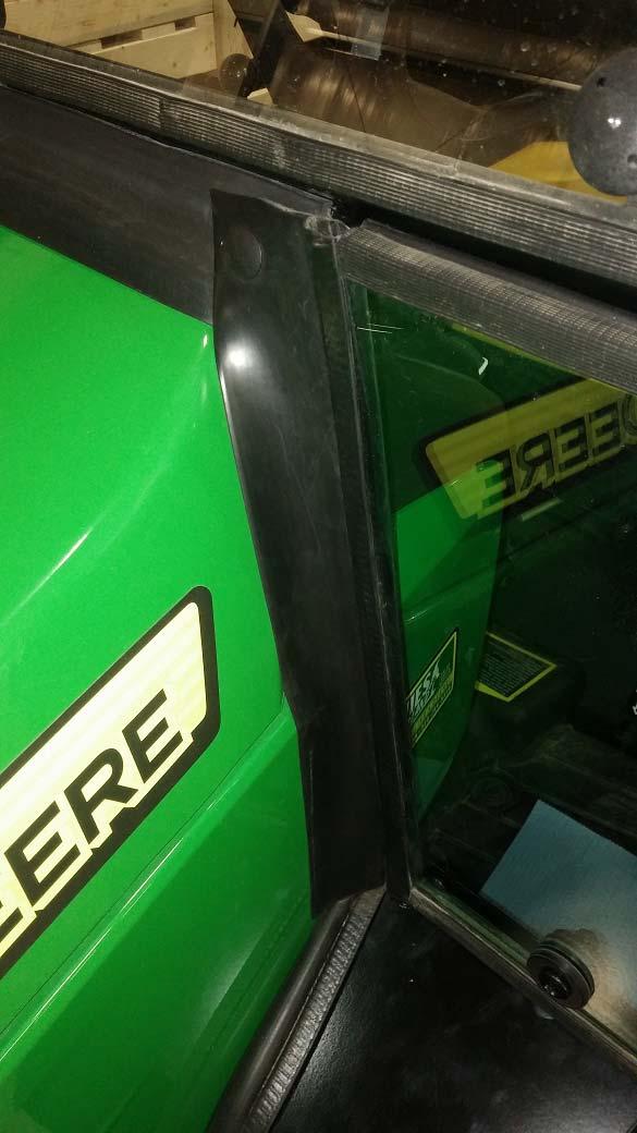
1 Cab Installation Instructions for John Deere One Series, 1023E, 1025R and 1026R Model Series A CAB KIT (Shown with GLASS DOORS KIT A-11859) FOR USE WITH OPTIONAL KITS; A GLASS DOORS WITH NON-OPENABLE WINDOWS A SOFT DOORS KIT A HEATER KIT A INTERIOR MIRROR KIT A REAR SLIDER WINDOW KIT (INSTALL EITHER TOP OR BOTTOM) A FRONT WORK LIGHTS MOUNT KIT (LIGHTS NOT INCLUDED) A REAR WORK LIGHT (ONE HELLA LIGHT INCLUDED) A AMBER BEACON STROBE KIT A EXTERIOR MIRRORS KIT A FAN KIT, 7 INCH RECIRCULATION AND DEFROST A HEATER QUICK DIS-CONNECT KIT A DOOR HOLD-OPEN KIT Page 1 of /30/2014
2 Cab Installation Instructions for John Deere One Series, 1023E, 1025R and 1026R Model Series Read these instructions and identify all components. Please retain these instructions for future reference and parts ordering information. Refer to kit components and figure 1 for general layout. Kit Components: ITEM QTY DESCRIPTION PART NO. 1 1 CAB SHELL REAR CORNER PANEL, LH MOUNT, FRONT LH MOUNT, FRONT RH PEDAL POCKET, LH PEDAL POCKET, RH REAR MOUNT REAR CORNER PANEL, RH REAR CORNER PANEL, LH TOP SEAL PANEL UNDER SEAT UNDER SEAT SEAL PAD FLASHER MOUNT, LH FLASHER MOUNT, RH POCKET FILLER, LH POCKET FILLER, RH DECK SEAL PAD, PEDALS WIRE EXTENSION, BLUE IGNITION ON WIRE HARNESS, EXTENSION FLASHERS, 30" DECK PLATE, LH DECK PLATE, RH FT WIRE DUCT WIRE HARNESS, MAIN FLAP SEAL, 11.52" LONG ANTI-SLIP PAD WITH PSA BACK SEAL PANEL FOR REAR VALVE Figure 1 Page 2 of /30/2014
3 Hardware Components; Cab Installation Instructions for John Deere One Series, 1023E, 1025R and 1026R Model Series ITEM QTY DESCRIPTION P/N A 6 BOLT, SOCKET HEAD, M16 x 80MM LG GR B 6 FLAT WASHER, M C 6 NUT, HEX M16 GR D 16 BOLT, BUTTON TRUSS, 1/4 x 1/2" LONG E 24 NUT, HEX FLANGED, 1/4" F 4 BOLT, HEX HEAD, 1/2 x 2.50" LONG G 4 WASHER, 1/2" TYPE N H 4 NUT, HEX CENTERLOCK, 1/2" J 3 BOLT, HEX HEAD, 3/8 x 3/4" LONG K 3 NUT, HEX FLANGED, 3/8" L 4 BOLT, 1/4" x 1.50" LONG M 6 SPACER, NON-LOADER MOUNT N 4 BOLT, BUTTON TRUSS, 5/16 x 3/4" LONG P 6 NUT, FLANGED, 5/16" Q 4 BOLT, BUTTON TRUSS, 1/4 x 1" LONG R 24 RACHET PLUG, 3/8" S 4 BOLT, BUTTON TRUSS, M8 x 25mm LONG T 4 LOCK WASHER, 5/16" U 12 NYLON TIE V 2 FT BUTYL TAPE W 10 ROSEBUD LOOM RETAINER.350" X 4 BOLT, ¼ x 1 LONG Y 4 BOLT, HEX HEAD, 3/4 x 3.50 LONG Z 4 NUT, HEX HEAD TOP-LOC, 3/ AA 2 P-CLAMP, ¾ BB 2 FLAT WASHER, 5/ CC 2 BOLT, HEX HEAD, 5/16 x 1.00 LONG Figure 2 Page 3 of /30/2014
4 Cab Installation Instructions for John Deere One Series, 1023E, 1025R and 1026R Model Series Machine Preparation; 1. If front loader is present, unhook loader from tractor. (Do not remove the loader mounts!) 2. Remove mower deck if attached. 3. Disconnect power from battery. 4. Tip seat forward. 5. On 1026R models, remove the lights mounted to the fenders. Note; To re-mount 1026R lights onto cab, order kit A-12000, Front Light Re-Mount Kit. 1023E models are not sold with fender lights, but can be bought separately. 6. Disconnect the rear flasher light wire harnesses. Remove the flasher lights and harnesses from the Roll bar and set aside. Front mounts installation for models without loader mounts, follow steps 7-8; 7. Secure front LH mount bracket (3) to the tractor s LH side frame rear loader mount location (Figure 3) using; (3) M16 x 80mm long, socket head bolt (A) (3) M16 flat washer (B) (3) M16 center lock nuts (C) (3) Non-Loader spacers (M) Hint; Slide at three bolts in first, place mount bracket over bolts and hand tighten nuts. Then use allen wrench and tighten all bolts. 8. Secure front RH mount bracket (4) to the tractor s RH side of frame using (Figure 3); (3) M16 x 80mm long, socket head bolt (A) (3) M16 flat washer (B) (3) M16 center lock nuts (C) (3) Non-Loader spacers (M) LH DECK Item 3 LH SIDE FRAME C B RH SIDE FRAME M A Figure 3 (Non-loader models) Item 4 Front mounts installation for models with loader mounts, follow steps 9-12; 9. Remove the (3) rear mounting bolts from the LH loader tower. 10. Secure front LH mount bracket (3) to the tractor s LH side of frame and rear loader mount location using (Figure 4); (3) M16 x 80mm long, socket head bolt (A) (3) M16 flat washer (B) (3) M16 center lock nuts (C) 11. Remove the (3) rear mounting bolts from the RH loader tower. Page 4 of /30/2014
 to the tractor s RH side of frame and rear loader mount location using; (3) M16 x 80mm long, socket head bolt (A) (3) M16 flat washer (B) (3) M16 center lock nuts")
 on top of bar and secure by re-using the two bolts from Step 13 (Figure 5). Item 7 Steps 13 & 14 Figure 5 Installing the cab; 15.")
5 Cab Installation Instructions for John Deere One Series, 1023E, 1025R and 1026R Model Series 12. Secure front RH mount bracket (4) to the tractor s RH side of frame and rear loader mount location using; (3) M16 x 80mm long, socket head bolt (A) (3) M16 flat washer (B) (3) M16 center lock nuts (C) LH LOADER ARM Item 4 A, B & C Only Figure 4 (With loader models) Rear mount installation; 13. Remove two rear bolts that secure the rear cross bar to the mount bracket (Figure 5). 14. Place rear mount (7) on top of bar and secure by re-using the two bolts from Step 13 (Figure 5). Item 7 Steps 13 & 14 Figure 5 Installing the cab; 15. Using a strap, spreader bar and overhead crane or forklift, carefully raise cab, remove crating and pallet. When lifting the cab onto the tractor, place strap so that the cab tilts forward. 16. Lower cab onto tractor and loosely secure front of cab using (Figure 7); (4) 1/2 x 2.50 long, hex head bolt (F) (4) 1/2" flat washer (G) (4) 1/2 center lock nut (H) 17. Align rear mount holes of cab with rear mount bracket holes. From inside of cab, place the under seat filler panel (Item 10) in front of the rear mount bracket, aligning the holes. Secure back of cab and under seat filler to rear mount bracket using (Figure 6); (3) 3/8 x 3/4 long hex head bolts (J) (3) 3/8 flange nuts (K) Note: If the end user plans to remove cab from tractor for summer use, keep the pallet to place the cab, once removed from tractor. Page 5 of /30/2014
 1/2")
 to LH cab frame tube using (Figure 7); (2) 1/4 x 1.")
6 Cab Installation Instructions for John Deere One Series, 1023E, 1025R and 1026R Model Series Torque bolts: Important! Using a torque wrench, torque all mounting hardware to the following torque specifications: 3/8 hardware to 30 FT-LB (41 N-M) 1/2 hardware to 70 FT-LB (95 N-M) M16x2x80mm bolts to 200 FT-LB (or 271 N-M) Step 17 Figure 6 Step 16 Step 18 Figure Secure LH deck plate (19) to LH cab frame tube using (Figure 7); (2) 1/4 x 1.5 long, bolts (L) (2) 1/4 flange nuts (E) Page 6 of /30/2014
 (2) 1/4 flange nuts (E) 20. Secure bottom of LH pedal pocket (5) to LH cab deck plate using (Figure 8); (2) 1/4 x 1 long, bolts (Q) (2) 1/4 flange nuts (E) 21.")
 to RH cab deck plate (Figure 9); (2) 1/4 x 1 long, bolts (Q) (2) 1/4 flange nuts (E) 25.")
 to back of cab using (2) 1/4 x 1/2 long, bolts (D) and (2) 1/4 flange nuts (E). 28.")
 and install the longer flap seal (23) to the bottom of corner panel.")
7 Cab Installation Instructions for John Deere One Series, 1023E, 1025R and 1026R Model Series 19. Secure RH deck plate (20) to LH cab frame tube using (2) 1/4 x 1.5 long, bolts (L) (2) 1/4 flange nuts (E) 20. Secure bottom of LH pedal pocket (5) to LH cab deck plate using (Figure 8); (2) 1/4 x 1 long, bolts (Q) (2) 1/4 flange nuts (E) 21. Remove both lower windows. 22. Secure top LH pedal pocket (5) to front lower angle of window mount (Figure 8); (2) 1/4 x 1/2 long, bolts (D) (2) 1/4 flange nuts (E) 23. Reinstall front lower LH window by reusing hardware. 24. Secure bottom of RH pedal pocket (6) to RH cab deck plate (Figure 9); (2) 1/4 x 1 long, bolts (Q) (2) 1/4 flange nuts (E) 25. Secure top RH pedal pocket (6) to front lower angle of window mount (Figure 9); (2) 1/4 x 1/2 long, bolts (D) (2) 1/4 flange nuts (E) 26. Reinstall front lower RH window by reusing hardware. Steps 21 & 26 Step 22 Item 5 Step 25 Step 25 Step 24 Item 6 Figure 8 Figure Secure LH rear corner panel (2) to back of cab using (2) 1/4 x 1/2 long, bolts (D) and (2) 1/4 flange nuts (E). 28. Secure LH rear corner panel top (9) to back of cab and corner panel (2) using (Figure 10) (2) 1/4 x 1/2 long, bolts (D) and (2) 1/4 flange nuts (E). Note: If installing cab on a 1023E tractor, remove the bubble rubble supplied with the corner panel (2) and install the longer flap seal (23) to the bottom of corner panel. Trim excess poly foam if present. (Figure 10, Note 28). 29. Secure RH rear corner panel (8) to back of cab using (Figure 11) (4) 1/4 x 1/2 long bolts (D) and (4) 1/4 flange nuts (E). Trim excess poly foam if present. Step 28 Item 2 Item 8 Note 28 Figure 10 Figure 11 Page 7 of /30/2014


 M8 x 15mm long, bolts (S) (2) 5/16 lock washers (T) 31.")
 (2) 5/16 flange nuts (P) 32.")
.")


 and secure to cab using rosebud clips (W) (Figures 14a and 14b) and ¼ holes")
8 Cab Installation Instructions for John Deere One Series, 1023E, 1025R and 1026R Model Series Note: For models 1023E and 1026R with a single flasher light, use the dual flasher remount bracket for remounting the light. The light will be centered on the bracket, leaving a gap on top and bottom. 30. Mount RH flasher light to RH flasher mount bracket (13) (Figure 12). Secure using; (2) M8 x 15mm long, bolts (S) (2) 5/16 lock washers (T) 31. Secure RH flasher light with bracket to RH rear side of cab (Figure 12) by using; (2) 5/16 x 3/4" long, bolts (N) (2) 5/16 flange nuts (P) 32. Route wires from flasher light thru universal grommet to the inside of cab (Figure 12). 33. Locate flasher wire extension harness (18). Tractors with dual flasher lights, match and reconnect all four wire colors from dual flasher lights to the original wire connections. Note; Tractors with single flasher lights, match wire colors, using three of the four wires, from single flasher lights to the original wire connections (One of the dark green wires will not be used). 34. Add loom (21) and secure to cab using rosebud clips (W) (Figures 14a and 14b) and ¼ holes already in the cab s rear panel. 35. Repeat steps 30 thru 34 using LH flasher mount bracket (12) onto LH side of cab (Figure 13). Item 13 Step 32 Item 14 Figure 12 (RH side shown) Figure 13 (LH side shown) Step 34 Figure 14a (RH side shown) Figure 14b (RH side shown) Page 8 of /30/2014
. 38.")

9 Cab Installation Instructions for John Deere One Series, 1023E, 1025R and 1026R Model Series Electrical Hook-Up: 36. Locate main relay-breaker wire harness. 37. Lift the tractor hood and remove both engine cover panels (Figure 15). 38. Route ends of main wire harness from battery area, along the inside driver side frame tube, to LH cab tube through a grommet located at the bottom of the battery panel (Figure 17). Hint; The easiest way to get the wire harness through the tube is to use a wire to pull the two main wires first, then pull the blue wire last. 39. Route the blue wire labeled, Ignition On from main wire harness to the tractor s electrical panel, located on RH side of cowl. Extend this blue wire by connecting a blue 36 wire extension (22), supplied with mount kit. 40. Use the blue T-tap connector to connect the blue wire to Ignition Run Power wire coming from the tractor s fuse block terminal F08 location (Figure 16). Removal of fuse panel may be required to get to the back side of panel. STEP 40 STEP 39 Locate F08 Wire behind panel Figure 15 Figure Remove the (2) 5/16 bolts that secure the switch panel to the cab frame header area. 42. Route remaining end of main wire harness up LH cab tube to fuse block. (Figures 18). Note: The LH front mount bolts may be removed to allow easier wire harness routing; Support cab before removing mount bolts. At the fuse block location, connect the red wire to the (+12V) post and the black wire to the (-12V) post. STEP 42 (-12V) STEP 47 STEP 37 STEP 42 (+12V) Figure 17 Page 9 of 28 Figure /30/2014
. 45.")

. 49. Check operation of dome light. On/Off. Dome light should go off if tractor key is turned off. 50.")
10 Cab Installation Instructions for John Deere One Series, 1023E, 1025R and 1026R Model Series 43. Reinstall switch panel. 44. Connect positive lead with the red wire from the main relay and breaker harness, to the +12VDC terminal of battery (Figure 17). 45. Connect negative lead with the black wire from the main relay and breaker harness, to the -12VDC terminal of battery (Figure 17). 46. Turn ignition key on and start tractor. 47. Check operation of front wiper; Hi, Lo and Off. When the switch on the wiper motor is turned off, wiper will run for a short period of time and then stop or park itself. Wiper should turn off when tractor key is turned off. 48. If switch panel has no power, check the breaker located on the red wire of the main relay and breaker harness. Reset breaker if needed (Figure 17). 49. Check operation of dome light. On/Off. Dome light should go off if tractor key is turned off. 50. Secure main loom to inside of driver side frame using (Figures 19 & 20); (2) P-clamps, ¾ (AA) (Inside of frame) (2) 5/16 x 1.00 long bolts (BB) (2) 5/16 Flat washers (CC) (2) 5/16 Flange nuts (P) 51. Coil excess wire harness and secure using nylon ties (U). Avoid any hot or moving parts. DO NOT SECURE WIRE HARNESS TO HIGH PRESSURE FUEL LINES! Inside of frame Figure 19 Figure 20 SEALING THE CAB: 52. Tip seat up and place under seat seal pad (11) textured side up, as shown in Figure Secure back to seal pad with 3 holes to rear cab panel using (6) 3/8 ratchet plugs (R) (Figure 21). 54. Overlap and secure LH/RH sides of seal pad to corner panels using (4) 3/8 ratchet plugs (R) (Figure 21). 55. Plug single hole in under seat pad (11) with (2) 3/8 ratchet plugs (R) (Figure 21). 56. Layout under seat seal pad around levers and seat. Tip seat down. STEP 53 STEP 55 STEP 54 Figure 21 Page 10 of /30/2014


 to LH")
 (2) 1/4 flange nuts (E) 60.")
 using (Figure 23); (2) 1/4 x 1/2")
 into small locations to")

11 Cab Installation Instructions for John Deere One Series, 1023E, 1025R and 1026R Model Series 57. Apply one deck seal (16) to deck, at LH pedal area shown in Figure Apply two deck seals (16) to deck, at RH pedal location as shown in Figure 23. STEP 59 STEP 60 STEP 57 STEP 58 Figure 22 Figure Secure LH lower front filler panel (14) to LH cab pedal pocket (5) using (Figure 22); (2) 1/4 x 1/2 long, bolts (D) (2) 1/4 flange nuts (E) 60. Secure RH lower front filler panel (15) to RH cab pedal pocket (6) using (Figure 23); (2) 1/4 x 1/2 long, bolts (D) (2) 1/4 flange nuts (E) 61. Cut to fit, butyl tape (V) into small locations to help seal cab (Figures 24-27). 62. Check operation of all levers and pedals to make sure of safe operation. V V V Figure 24 Figure 25 V V Figure 26 Figure 27 Page 11 of /30/2014

")
 and a ¾ top lock nut (BB) into")
 with retainer")
.")
12 Cab Installation Instructions for John Deere One Series, 1023E, 1025R and 1026R Model Series 63. Important! The ROPS is not allowed to fold-down once the cab is installed. To install Antifolding ROPS hardware, remove the folding pin (DD) with retainer clip (EE) and rotor clip (FF) (Figures 28-30) and install a ¾ x 3-1/2 long bolt (AA) and a ¾ top lock nut (BB) into each pin location on each side of ROPS. Note; If the cab is ever removed, folding pins (DD) with retainer clips (EE) and rotor clips (FF) should be re-installed, with the ROPS top hoop in the upright position (Figure 28). Y Z FF DD Figure 29 (LH Side) EE Z Y Figure 28 Figure 30 (RH Side) Page 12 of /30/2014

13 Cab Installation Instructions for John Deere One Series, 1023E, 1025R and 1026R Model Series 64. On 1023E models, under seat side closeout panels are not sold with the tractors and can be purchased from a John Deere dealer, if preferred. Refer to part numbers 1-8 of Figure 31 for items and part numbers. Figure 31 Revised ; Added flap seal (23) to mount kit for 1023E tractor models; Changed under seat seal panel for 3-point valve clearance. Revised ; Added notes for 1025R tractor models Revised ; Updated for 1025R requirements. Revised ; Added addendum sheet for machines with BLV10351 valves Cab installation is now complete. If you have any questions or comments, contact; Page 13 of /30/2014
14 Cab Installation Instructions for John Deere One Series, 1023E, 1025R and 1026R Model Series Addendum Sheet Tractor models with optional attachment and rear valve BLV10351 installed A. Remove RH corner seal rubber from RH corner panel by removing (8) ratchet plugs. B. Place RH corner seal with valve cutout slot on the inside of RH corner panel. C. Secure RH corner seal using (4) 3/8 ratchet plugs on the inside and (4) 3/8 ratchet plug on the outside of panel. STEP A STEP B STEP C Page 14 of /30/2014
15 Page 15 of 28
16 Page 16 of 28

17 Page 17 of 28
18 Page 18 of 28
19 Page 19 of 28
20 Page 20 of 28
21 Page 21 of 28
22 Page 22 of 28

23 Page 23 of 28
24 Page 24 of 28
25 Page 25 of 28
26 Page 26 of 28
27 Page 27 of 28
28 Page 28 of 28
A CAB FRAME WITH A KIOTI ROOF KIT ON KIOTI CK SERIES TRACTOR (SHOWN WITH OPTIONAL HARD DOORS) OPTIONAL ACCESSORIES SOLD SEPARATELY
 OPTIONAL ACCESSORIES SOLD SEPARATELY") A-11718 CAB FRAME WITH A-11682 KIOTI ROOF KIT ON KIOTI CK SERIES TRACTOR (SHOWN WITH OPTIONAL HARD DOORS) OPTIONAL ACCESSORIES SOLD SEPARATELY A-11636 VINYL SOFT DOORS KIT A-11637 HARD DOORS WITH NON-SLIDER
A-11718 CAB FRAME WITH A-11682 KIOTI ROOF KIT ON KIOTI CK SERIES TRACTOR (SHOWN WITH OPTIONAL HARD DOORS) OPTIONAL ACCESSORIES SOLD SEPARATELY A-11636 VINYL SOFT DOORS KIT A-11637 HARD DOORS WITH NON-SLIDER
JODALE PERRY. Parts List & Mounting Instructions. Jacobsen HR9016 JDP BUILT FOR LIFE
 JODALE PERRY Parts List & Mounting Instructions Jacobsen HR9016 JDP BUILT FOR LIFE Jacobsen HR9016 Mounting Instructions Standard Parts 1 - LH Rear Mounting Bracket 1 - RH Rear Mounting Bracket 1 - Front
~ Manufactured. '-ccz CR, ", MOUNTING INSTRUCTIONS. With Replacement Parts Listing For A OPTIONS
 '-ccz CR, ", '..." 5 ' '.", ;,...,...'.,!e./i,.,.',.' ',', MOUNTING INSTRUCTIONS With Replacement Parts Listing For TORO 355-D/455-D A-47 ROPS CAB I- OPTIONS 4-3069 Heater Kit Option 4-307 Flashing Light
JOHN DEERE GATOR SWITCH PANEL INSTRUCTIONS FITS 1GTRXUV2 AND 1GTRXUV4 CABS (p/n: 1XUVSP)
") P. 1 of 5 JOHN DEERE GATOR SWITCH PANEL INSTRUCTIONS FITS 1GTRXUV2 AND 1GTRXUV4 CABS (p/n: 1XUVSP) Note: Harness Extension Kit Required for 4 Passenger (p/n: 1XUV4WHEK) This manual is the property of the
P. 1 of 5 JOHN DEERE GATOR SWITCH PANEL INSTRUCTIONS FITS 1GTRXUV2 AND 1GTRXUV4 CABS (p/n: 1XUVSP) Note: Harness Extension Kit Required for 4 Passenger (p/n: 1XUV4WHEK) This manual is the property of the
Assembly Instructions
 Assembly Instructions Part Number Description Model Approx. Assembly Time 99994-049 Cab Enclosure MULE SX 3-4 Hours WARNING Improper installation of this accessory could result in an accident causing serious
INSTALLATION & OWNER S MANUAL
 Rev. A, p. of 0 INSTALLATION & OWNER S MANUAL MASSEY FERGUSON GC2400 cab kit p/n MFGC2400 Installation Instructions The contents of this envelope are the property of the owner. Be sure to leave with the
INSTALLATION & OWNER S MANUAL
 INSTALLATION & OWNER S MANUAL CAB INSTALLATION INSTRUCTIONS KUBOTA GRAND L 30 SERIES HARD SIDED CAB ENCLOSURE (p/n 1KU3AS) SOFT SIDED CAB ENCLOSURE (p/n 1KU3SS) This Curtis Cab is designed and manufactured
INSTALLATION & OWNER S MANUAL
 p. 1 of 15 INSTALLATION & OWNER S MANUAL YANMAR Sc2450 cab kit with hard doors and soft rear curtain Curtis p/n: 1CYSC2450AS The contents of this envelope are the property of the owner. Be sure to leave
INSTALLATION OF THE ENCLOSURE FOR THE MULE 3010 TRANS INSTALLATION GUIDE FOR THE MULE 3000 TRANS ENCLOSURE P. 1. Sept 07
 INSTALLATION GUIDE FOR THE MULE 3000 TRANS ENCLOSURE P. 1 INSTALLATION OF THE ENCLOSURE FOR THE MULE 3010 TRANS Sept 07 www.essexmfg.com PO Box 92864 Southlake, TX 76092 Ph:888-643-7739 INSTALLATION GUIDE
John Deere 4115 Boxer
 John Deere 4115 Boxer Parts List & Mounting Instructions Jodale Perry Printed: 2004/07 Standard Parts List Qty Description Photo L&R Rear Mounting Brackets L&R Front Mounting Brackets 2 Front Bracket Spacers
John Deere 4110 Boxer
 John Deere 4110 Boxer Parts List & Mounting Instructions Jodale Perry Printed: 2004/07 Standard Parts List Qty Description Photo L&R Rear Mounting Brackets L&R Front Mounting Brackets 2 Front Bracket Spacers
New Holland Workmaster 25s
 New Holland Workmaster 25s ROPS Cab ** Shown with optional equipment New Holland Workmaster 25s ROPS Cab This ROPS cab is designed and built to fit the New Holland Workmaster 25s tractor. Designed and
MOUNTING INSTRUCTIONS JOHN DEERE GATOR NON-ROPS CAB
 MOUNTING INSTRUCTIONS JOHN DEERE GATOR NON-ROPS CAB FITS 4X2 & 6X4 GATORS A-11112, A-11224, A-11225, A-11226 MANUFACTURED BY: BOX 70 LITCHFIELD, MINNESOTA 55355-0070 (320) 693-3221 Fax: (320) 693-7252
INSTALLATION & OWNER S MANUAL
 INSTALLATION & OWNER S MANUAL CAB INSTALLATION INSTRUCTIONS JOHN DEERE 4000 SERIES (4500/4600/4700) (4510/4610/4710) (4120/4320/4520/4720) HARD SIDED CAB ENCLOSURE (p/n 1JD4120AS) SOFT SIDED CAB ENCLOSURE
INSTALLATION & OWNER S MANUAL
 Rev. C p. 1 of 21 INSTALLATION & OWNER S MANUAL F5205 HARD SIDED CAB KIT INSTALLATION & OWNER S MANUAL The contents of this envelope are the property of the owner. Be sure to leave with the owner when
INSTALLATION INSTRUCTIONS
 INSTALLATION INSTRUCTIONS Accessory S Application 2011 ODYSSEY Publications No. AII 43917 Issue Date SEP 2010 PARTS LIST Fog Light Kit P/N 08V31-TK8-100 Left fog light 20A Fuse Relay Right fog light Light
DOOR KIT P/N , APPLICATION BEFORE YOU BEGIN KIT CONTENTS. Verify accessory fitment at Polaris.com.
 DOOR KIT P/N 2882561, 2882562 APPLICATION Verify accessory fitment at Polaris.com. BEFORE YOU BEGIN Read these instructions and check to be sure all parts and tools are accounted for. Please retain these
INSTALLATION & OWNER S MANUAL
 p. 1 of 13 INSTLLTION & OWNER S MNUL Kubota X 70 Series Cab (fits X2370, X2670, and X25D) (p/n: 1KX70S Steel Cab) (p/n: 1KX70SS Vinyl Cab) The contents of this envelope are the property of the owner. e
INSTALLATION & OWNER S MANUAL
 INSTALLATION & OWNER S MANUAL CAB INSTALLATION INSTRUCTIONS JOHN DEERE 3000 SERIES (4200/4300/4400) (4210/4310/4410) & (3120/3320/3520/3720) HARD SIDED CAB ENCLOSURE (p/n 1JD3520AS) SOFT SIDED CAB ENCLOSURE
Kubota B2910, B7800 Boxer
 Kubota B2910, B7800 Boxer Parts List & Mounting Instructions Jodale Perry Printed: 2004/12 Standard Parts List Qty Description Photo L&R Rear Brackets L&R Front Brackets 2 Front Bracket Spacers (No-Loader)
John Deere 4210, 4310, 4410 Soft Cab
 John Deere 4210, 4310, 4410 Soft Cab Parts List & Mounting Instructions Jodale Perry Printed: 2004/08 Standard Parts List Qty Description Photo L&R Rear Brackets L&R Front Brackets 4 Front Bracket Spacers
INSTALLATION & OWNER S MANUAL
 Rev. C, p. of 2 INSTALLATION & OWNER S MANUAL KUBOTA B2650/3350 Hard Sided Cab p/n KB33AS Soft Sided Cab p/n KB33SS Installation Instructions The contents of this envelope are the property of the owner.
Part Number: TAV-713 TOYOTA AVALON LED DRL
 Part Number: TAV-713 Kit Contents Item # Quantity Reqd. Description 1 2 DRL s bezels w/led DRL 2 1 Driver Box 3 1 Harness bag 4 1 User s card 5 1 Cushion pad 6 1 Switch 7 2 Drill Jigs Hardware Bag Contents
INSTALLATION MANUAL P2068. Level of Difficulty. Parts List. Product Image. Notes and Maintenance. Tools Required. Easy
 INSTALLATION MANUAL P2068 Parts List 1 Grille guard 1 Driver / left frame mounting bracket 1 Passenger / right frame mounting bracket 1 Driver / left top mounting bracket 1 Passenger / right top mounting
TOYOTA TACOMA EC REARVIEW MIRROR Preparation
 Preparation Part Number: PT374-35052 Kit Contents Item # Quantity Reqd. Description 1 1 AD Mirror Assembly 2 1 Hardware bag Hardware Bag Contents Item # Quantity Reqd. Description 1 1 T-tap Connectors,
INSTALLATION INSTRUCTIONS
 INSTALLATION INSTRUCTIONS Accessory Application Publications No. P/N 08E49-S2A-100 2004 S2000 AII 26325 Issue Date OCT 2003 PARTS LIST Hood switch harness TOOLS AND SUPPLIES REQUIRED #2 Phillips screwdriver
TOYOTA FJ CRUISER TVIP V5 Preparation
 Preparation Part Number: 08586-36822 Conflicts Do not be installed in vehicles with factory Anti-theft alarm, or Vehicle without Factory Keyless Entry Systems. Recommended Sequence of Application Item
John Deere 4510, 4610, 4710 Boxer
 John Deere 4510, 4610, 4710 Boxer Parts List & Mounting Instructions Jodale Perry Printed: 2004/02 Standard Parts List Qty Description Photo L&R Rear Mounting Brackets (Upper&Lower) L&R Front Mounting
TOYOTA TUNDRA TVIP V4 Preparation
 Preparation Part Number: PT398-00100 PT398-00100-AA Conflicts Do not install into vehicles without RKE system. Recommended Sequence of Application Item # Accessory 1 TVIP/RES Any TVIP or RES system 2 XM
New Holland TC 29DA, 33DA Boxer
 New Holland TC 29DA, 33DA Boxer Parts List & Mounting Instructions Jodale Perry Printed: 2004/10 Standard Parts List Qty Description Photo L&R Front Bracket Weldment L&R Rear Bracket Weldment 4 No-Loader
INSTALLATION INSTRUCTIONS
 Accessory Application Publication No. INSTALLATION INSTRUCTIONS HORN MOUNT P/N 08Z77-HL4-A00 SXS1000M3/M3P/M5D/M5P Honda Dealer: Please give a copy of these instructions to your customer. MII 15262 Issue
TOYOTA RAV TRAILER WIRE HARNESS Section I Installation Preparation
 Section I Installation Preparation Part Number: 08921-42900 Kit Contents Item # Quantity Reqd. Description 1 1 Converter 2 1 Wire harness 3 1 Sub wire harness No.1 4 2 Plastic Tie (300mm) 5 21 Plastic
POLY TIP-DOWN WINDSHIELD KIT
 POLY TIP-DOWN WINDSHIELD KIT P/N 2883261 APPLICATION Verify accessory fitment at Polaris.com. BEFORE YOU BEGIN Read these instructions and check to be sure all parts and tools are accounted for. Please
INSTALLATION INSTRUCTIONS
 INSTALLATION INSTRUCTIONS Accessory S Application 2014 ODYSSEY Publications No. AII 49550 Issue Date JUNE 2013 PARTS LIST Fog Light Kit P/N 08V31-TK8-100A 16 Wire ties (Some may not be used) Left fog light
TOYOTA im INTERIOR LIGHT KIT Preparation
 Preparation Part Number: PT922-12170 Kit Contents Item # Quantity Reqd. Description 1 1 Main Wire Harness 2 1 Switch 3 1 Switch Header 4 1 ECU 5 1 ECU Bracket 6 1 Hardware Kit 7 1 Instruction Card 8 1
TOYOTA FJ CRUISER AIR DAM/LIGHT BAR Preparation
 Preparation Part Number: PT278-35071 Kit Contents Item # Quantity Reqd. Description 1 1 Air Dam / Light Bar Hardware Bag 1 Contents Item # Quantity Reqd. Description 1 2 Screw, M6x33mm, Wafer Head 2 2
INSTALLATION & OWNER S MANUAL
 Rev. D, p. 1 of 14 INSTALLATION & OWNER S MANUAL Bobcat CT 230 and KIOTI CK30 cab kit with hard doors and soft rear curtain p/n 1BCT230 & 1KTCK30 The contents of this envelope are the property of the owner.
Instructions for 2-row monitoring only
 Installation Instructions for CaseIH cotton picker models: Instructions for 2-row monitoring only Ensure the model numbers shown above correspond to the machine model. If you receive the incorrect installation
JOHN DEERE Series Cab MOUNTING INSTRUCTIONS. Fits with 2 post folding ROPS mower, sweeper, snow blower or blade options A-11241
 JOHN DEERE 1400-1500 Series Cab MOUNTING INSTRUCTIONS Fits with 2 post folding ROPS mower, sweeper, snow blower or blade options Manufactured by: A-11241 BOX 70 LITCHFIELD, MINNESOTA 55355-0070 (320) 693-3221
TOYOTA SIENNA XM SATELLITE RADIO Preparation
 Preparation Part Number: Mounting Kit: PT546-08070 Tuner Assy: 86180-0W031 Tuner Assy Kit Contents (86180-0W031) Item # Quantity Reqd. Description 1 1 Tuner Assy, Stereo Component Mounting Kit Contents
INSTALLATION INSTRUCTIONS FORD F-150 2WD & 4WD RETAINS FACTORY TOW HOOKS PART #P3063
 INSTALLATION INSTRUCTIONS FORD F-150 2WD & 4WD RETAINS FACTORY TOW HOOKS PART #P3063 PARTS LIST: 1 Grille Guard 2 10-1.5mm Nylon Lock Nuts 1 Driver/Left Frame Mounting Bracket 4 12mm Plastic Washers 1
2015 Ford F150 Front Bumper w/ LED
 PARTS LIST: 2015 Ford F150 Bumper w/ LED 1 Bumper Assembly 4 8mm Lock Washers 1 Driver/left L Bracket (center LED light) 2 8mm Hex Nuts 1 Passenger/right L Bracket (center LED light) 2 6mm x 20mm Button
INSTALLATION & OWNER S MANUAL
 INSTALLATION & OWNER S MANUAL CAB INSTALLATION INSTRUCTIONS MASSEY FERGUSON TGX SERIES SOFT SIDED CAB ENCLOSURE (p/n MFTGXSS) This Curtis Cab is designed and manufactured for use only as reasonable weather
Installation Guide for Rough Country 30 in. Chrome Series LED Light Bar w/ Hood Mounting Brackets
 Installation Guide for Rough Country 30 in. Chrome Series LED Light Bar w/ Hood Mounting Brackets Installation Time: 1 Hour Tools Required Trim removal tool (plastic or wood to prevent scratches on the
INSTALLATION & OWNER S MANUAL
 INSTALLATION & OWNER S MANUAL CAB INSTALLATION INSTRUCTIONS JOHN DEERE GATOR HPX and/or XUV HARD SIDED CAB ENCLOSURE (p/n: 1GTR44AS) SOFT SIDED CAB ENCLOSURE (p/n: 1GTR44SS) 111 HIGGINS STREET, WORCESTER,
INSTALLATION INSTRUCTIONS
 INSTALLATION INSTRUCTIONS Accessory REMOTE CONTROL Application 2008 CR-V Publications No. AII 35843-38422 Issue Date DEC 2007 PARTS LIST Caution label Remote Engine Starter Kit P/N 08E91-E22-100B Transmitter
P/N Rev 01 04/14-1- NOTE: If you are ordering hinges for your rear doors, order and/or
 REAR CANVAS DOOR KIT 900 XP RANGER CREW P/N 2879899 Application RANGER 900 XP CREW Before you begin, read these instructions twice and check to be sure all parts and tools are accounted for. Please retain
GENUINE PARTS INSTALLATION INSTRUCTIONS
 GENUINE PARTS INSTALLATION INSTRUCTIONS DESCRIPTION: APPLICATION: PART NUMBER: Electronic Tailgate Lock Kit Nissan Titan 999M2-W3005 KIT CONTENTS: Item Qty. Part Description Service Part Number A 1 Electronic
INSTALLATION INSTRUCTIONS
 INSTALLATION INSTRUCTIONS Accessory P/N 08E10-TA0-100 Application 2008 ACCORD 2-AND 4-DOOR Publications No. AII 35358 Issue Date AUG 2007 PARTS LIST Ambient Light Kit 2 Ambient lights Fuse label Washer
AUDIO KIT P/N APPLICATION BEFORE YOU BEGIN KIT CONTENTS. Verify accessory fitment at Polaris.com.
 AUDIO KIT P/N 2882696 APPLICATION Verify accessory fitment at Polaris.com. BEFORE YOU BEGIN Read these instructions and check to be sure all parts and tools are accounted for. Please retain these installation
GENUINE PARTS INSTALLATION INSTRUCTIONS
 GENUINE PARTS INSTALLATION INSTRUCTIONS DESCRIPTION: APPLICATION: PART NUMBER: KIT CONTENTS: Illuminated Kick Plate Maxima (Applicable ONLY to U.S. Market Vehicles with Build Date June 2012 or later) 999G6
Illustrated Parts Manual
 Illustrated Parts Manual Models 522D LoPro 524D LoPro S/N 0900 P/N - 948-403 Revised July 6, 2007 INTRODUCTION Table of Contents SECTION INTRODUCTION Table of Contents... - thru -4 Alphabetical Index...
2-row and All-row systems included.
 Ag Leader Technology Cotton Picker Installation Installation Instructions for John Deere cotton picker models: 2-row and All-row systems included. IMPORTANT: Ensure the model numbers shown above correspond
INSTALLATION INSTRUCTIONS
 INSTALLATION INSTRUCTIONS Accessory Application Publications No. / All 33055 2007 PILOT (LX) Issue Date JULY 2006 Player Attachment Kit (sold separately) : P/N 08B06-S9V-100A Cassette Player (sold separately)
P3066 INSTALLATION MANUAL
 P3066 INSTALLATION MANUAL Parts List 1 Grille guard 1 Driver / left frame bracket Level of Difficulty Moderate Scan for helpful install tips 1 Passenger / right frame bracket 1 Driver / left top bracket
INSTALLATION INSTRUCTIONS
 INSTALLATION INSTRUCTIONS Accessory Application Publications No. BII 39889 HITCH 2009 MDX Issue Date JULY 2008 PARTS LIST Trailer Hitch Kit P/N 08L92-STX-200 Trailer Harness Kit P/N 08L91-STX-200 Trailer
INSTALLATION INSTRUCTIONS
 INSTALLATION INSTRUCTIONS Accessory Application Publications No. SYSTEM 2005 ACCORD All 27511 (DX, LX) 2-AND 4-DOOR Issue Date AUG 2004 PARTS LIST Security System Attachment (LX): P/N 08E55-SDA-100A Unit
INSTALLATION INSTRUCTIONS
 INSTALLATION INSTRUCTIONS Accessory REMOTE CONTROL ENGINE STARTER Application 2010 CR-V Publications No. AII 42612-42916 Issue Date OCT 2009 PARTS LIST Remote Engine Starter Unit Kit P/N 08E91-E22-101B
Instructions for 2-row monitoring only
 Installation Instructions for CaseIH cotton picker models: Instructions for 2-row monitoring only CAUTION: Ensure the model numbers shown above correspond to the machine model. If you receive the incorrect
INSTALLATION & OWNER S MANUAL
 Rev. G, p. 1 of 19 INSTALLATION & OWNER S MANUAL YANMAR Sc SERIES cab kit with hard doors and soft rear curtain Curtis p/n: 1CYSC1AS Yanmar p/n: 59A40056727 Optional Hard Rear Panel Curtis p/n: SC100-06A
Procedure. These guidelines can be found in the "Accessory Installation Practices" document.
 Toyota Tundra 207 LED Illumination Package Part Number: 0006-00069 (Interior and Exterior) Accessory Code: LL000 Conf licts V ehicles with Option Code BZ Color Applicability/Trim Level Kit Content 4 Puddle
New Holland TC30 Parts List & Mounting Instructions
 New Holland TC30 Parts List & Mounting Instructions Jodale Perry Printed: 2003/07 Standard Parts List Qty Description Photo Front Brackets 4 Front Bracket Spacers Rear Brackets Rear Bracket Axle Supports
2015 Mustang Lightbar (All Models) CDC#
 CDC#") 2015 Mustang Lightbar (All Models) CDC# 1511-7000-01 Components: 1 CDC Lightbar Note: READ instructions before starting installation!!! CDC Part# Driver side bracket 0511-6001-05 Passenger side bracket
2015 Mustang Lightbar (All Models) CDC# 1511-7000-01 Components: 1 CDC Lightbar Note: READ instructions before starting installation!!! CDC Part# Driver side bracket 0511-6001-05 Passenger side bracket
INSTALLATION INSTRUCTIONS
 INSTALLATION INSTRUCTIONS Accessory Application Publications No. BII 25830 2004 MDX Issue Date SEP 2003 PARTS LIST 2 Clips Trailer Hitch Kit: P/N 08L92-S3V-200A Receiver cover Trailer hitch Harness Kit:
INSTALLATION INSTRUCTIONS
 Accessory Application Publication No. INSTALLATION INSTRUCTIONS WINCH MOUNT KIT P/N 08L77-HL3-A00 SXS700M4/M2 Honda Dealer: Please give a copy of these instructions to your customer. MII 14607 Issue Date
INSTALLATION INSTRUCTIONS
 INSTALLATION INSTRUCTIONS Accessory Application Publications No. AII 30518 KIT 2006 PILOT Issue Date NOV 2005 NOTE: Accessory ATF and power steering coolers are required when installing the trailer hitch.
INSTALLATION & OWNER S MANUAL
 Rev. E p. of 3 INSTALLATION & OWNER S MANUAL V446 Front Cab Kit and V446 Rear Cab Kit for RTV 40 INSTALLATION & OWNER S MANUAL The contents of this envelope are the property of the owner. Be sure to leave
PRELIMINARY INSTALLATION INSTRUCTIONS PARTS LIST. Combination light switch Right fog light. 4 Self-tapping washer-screws.
 INSTALLATION INSTRUCTIONS Accessory S P/N 08V31-SCV-100D Application 2009 ELEMENT (SC) Publications No. AII 40515 Issue Date OCT 2008 PARTS LIST Combination light switch Right fog light Left fog light
INSTALLATION & OWNER S MANUAL
 Page 1 of 16 INSTALLATION & OWNER S MANUAL YAMAHA VIKING CAB KIT WITH HARD DOORS p/n: 1YAMVK fits model years 2014- (fits Yanmar Bull model years 2017-) NOTE: By design, the doors are made to not be removable!
 INSTALLATION INSTRUCTIONS Accessory Application Publications No. AII 38133-38406 HITCH 2008 ODYSSEY Issue Date NOV 2007 NOTE: A required heavy-duty power steering cooler, ATF cooler and air duct are required
INSTALLATION & OWNER S MANUAL
 Rev. A, p. 1 of 6 INSTALLATION & OWNER S MANUAL YANMAR SA-424 WINDSHIELD KIT P/N 1CYSA4WS FITS SA-424 TRACTORS WITH 4 POST ROPS The contents of this envelope are the property of the owner. Be sure to leave
TOYOTA tc HANDS FREE BLU LOGIC Preparation
 TOYOTA tc 2011- HANDS FREE BLU LOGIC Preparation Part #: PT923-00111 Conflicts: JBL Audio, Factory Navigation NOTE: Part number of this accessory may not be the same as the part number shown. Kit Contents:
Ref Qty Part Description Part Number -1- Kit ( ) Contents:
 Contents:") REAR CANVAS DOOR KIT 900 XP RANGER CREW P/N 2879899 Application RANGER 900 XP CREW Before you begin, read these instructions twice and check to be sure all parts and tools are accounted for. Please retain
REAR CANVAS DOOR KIT 900 XP RANGER CREW P/N 2879899 Application RANGER 900 XP CREW Before you begin, read these instructions twice and check to be sure all parts and tools are accounted for. Please retain
John Deere 1420, 1435, 1445 Soft Side
 John Deere 1420, 1435, 1445 Soft Side Parts List & Mounting Instructions Jodale Perry Printed: 2003/07 Standard Parts List Qty Description Photo L&R L&R Rear Cab Brackets Rear Cab Side Panels (Plastic)
INSTALLATION INSTRUCTIONS
 INSTALLATION INSTRUCTIONS PARTS LIST Accessory Application Publications No. TRX420 (All) MII 13032 WINCH KIT P/N 08L94-HP5-100 Accessory Weight 35 lbs (16 kg) Honda Dealer: Please give a copy of these
TOYOTA 4RUNNER COLD AIR INTAKE FJ CRUISER Preparation
 Preparation Part Number: PTR03-89100 Kit Contents Item # Quantity Reqd. Description 1 1 Air Filter (P/N: PTR43-00083) 2 1 Upper Air Box 3 1 Lower Air Box 4 1 Hump Coupler 5 1 Throttle Body Coupler 6 1
ASSEMBLY INSTRUCTIONS
 CONTENTS ASSEMBLY INSTRUCTIONS... 1 TO THE DEALER... 1 SAFETY... 1 UNPACKING AND CHECKING PARTS... 2 Unpacking Wooden Crate...2 Checking Parts...3 TRACTOR PREPARATION... 4 ASSEMBLY... 4 Boom Assembly...4
INSTALLATION INSTRUCTIONS
 INSTALLATION INSTRUCTIONS Accessory Application Publications No. All 12035 SYSTEM 2012 RIDGELINE Issue Date NOV 2011 PARTS LIST Security System Attachment Kit: P/N 08E55-SJC-101 Flange bolt Unit bracket
INSTALLATION INSTRUCTIONS
 Accessory Application Publication No. INSTALLATION INSTRUCTIONS WINCH MOUNT P/N 08L73-HL4-F01 After 16 SXS1000M3/M3P/M3LE SXS1000M5P/M5D/M5LE MII 16083 Issue Date February 2017 PARTS LIST No. Description
TOYOTA TACOMA TVIP V3 (RS3200) Section I - Installation Preparation
 Section I - Installation Preparation") Section I - Installation Preparation Part Number: 08586-04810 Section I - Installation Preparation Kit Contents Item # Quantity Reqd. Description 1 1 Wire Harness 2 1 Status Monitor 3 1 Piezo Buzzer 4
Section I - Installation Preparation Part Number: 08586-04810 Section I - Installation Preparation Kit Contents Item # Quantity Reqd. Description 1 1 Wire Harness 2 1 Status Monitor 3 1 Piezo Buzzer 4
Part Number: TAV-713. Kit Contents Item # Quantity Reqd. Description 1 2 DRL s bezels w/led DRL. Hardware Bag Contents.
 Date: 09.04.2013 TOYOTA AVALON 2013 - LED DRL Part Number: TAV-713 Kit Contents Item # Quantity Reqd. Description 1 2 DRL s bezels w/led DRL 2 1 Driver Box 3 1 Harness bag 4 1 User s card 5 1 Cushion pad
TOYOTA SIENNA TRAILER WIRE HARNESS Preparation
 Preparation Part Number: PT791-08150 (non-se) PT791-08102 (SE only) Kit Contents Item # Quantity Reqd. Description 1 1 Trailer Module Harness 2 1 4-Flat Harness 3 1 Battery Power Wire Harness 4 1 Mounting
INSTALLATION INSTRUCTIONS
 INSTALLATION INSTRUCTIONS Accessory Application Publications No. CIVIC All 30175-31616 2 AND 4-DOOR P/N 08E10-SNA-100 Issue Date DEC 2005 NOTE: The interior illumination lights cannot be installed on 2-door
INSTALLATION INSTRUCTIONS
 INSTALLATION INSTRUCTIONS Accessory TRAILER HITCH Application 2011 ODYSSEY Publications No. AII 43937 Issue Date SEP 2010 PARTS LIST Trailer Hitch Kit P/N 08L92-TK8-100 Trailer Hitch Harness Kit P/N 08L91-TK8-100
INSTALLATION INSTRUCTIONS
 INSTALLATION INSTRUCTIONS Accessory Application Publications No. 2003 ELEMENT AII 24318 Issue Date DEC 2002 PARTS LIST Trailer Hitch Kit P/N 08L92-SCV-100 4 Bolts, 12 x 35 mm Trailer hitch U-bolt 2 Nuts,
Please note that these instructions apply to the Toyota Towing Wire Harness. The part you re looking for is PT
 This download was hosted by LanderFan.com, your source of tips, tricks, hacks, how-to articles, and other newsy tidbits related to the new (2014+) Toyota Highlander.! Please note that these instructions
INSTALLATION INSTRUCTIONS
 INSTALLATION INSTRUCTIONS Accessory Accessory Hands Free Link Application 2008 ACCORD 2 AND 4-DOOR Publications No. AII 38281 Issue Date NOV 2007 PARTS LIST Attachment Kit P/N 08E02-TA0-100 trim retainer
Assembly Instructions
 Assembly Instructions Part Number Description Model Approx. Assembly Time 99994-0903 Windshield Wiper Kit Mule SX 1 Hour WARNING Improper installation of this accessory could result in an accident causing
INSTALLATION INSTRUCTIONS
 INSTALLATION INSTRUCTIONS Accessory Application Publications No. AII 26031 2004 ODYSSEY Issue Date AUG 2003 NOTE: You cannot install the subwoofer in a vehicle equipped with both an under seat Navigation
INSTALLATION INSTRUCTIONS
 INSTALLATION INSTRUCTIONS Accessory Application Publications No. AII 27367 HITCH 2005 ODYSSEY Issue Date DEC 2004 NOTE: An optional heavy-duty power steering cooler, ATF cooler and air duct are required
 INSTALLATION INSTRUCTIONS Accessory Application Publications No. 2010 CIVIC All 42479 2- AND 4-DOOR P/N 08E10-SNA-110 Issue Date AUG 2009 NOTE: The interior illumination lights cannot be installed on 2-door
INSTALLATION INSTRUCTIONS
 INSTALLATION INSTRUCTIONS Accessory ENGINE BLOCK (L4) P/N 08T44-TA0-100 Application 2008 ACCORD 2-AND 4-DOOR Publications No. AII 35355 Issue Date AUG 2007 PARTS LIST Engine block heater Coolant concentration
SCION xa AUTO-DIMMING MIRROR Preparation
 Preparation Part Number: PT374-52040 (Compass) PT374-21050 (Homelink) Kit Contents Item # Quantity Reqd. Description 1a 1 AD Mirror Assembly w/compass & Map Lights (P/N PT374-52040) 1b 1 AD Mirror Assembly
INSTALLATION & OWNER S MANUAL
 INSTALLATION & OWNER S MANUAL CAB INSTALLATION INSTRUCTIONS MASSEY FERGUSON THX FOR MASSEY FERGUSON 528, 53, AGCO ST28A, ST33A, CHALLENGER MT255B SOFT SIDED CAB ENCLOSURE (p/n MFTHXSS) This Curtis Cab
INSTALLATION INSTRUCTIONS
 INSTALLATION INSTRUCTIONS Accessory Application Publications No. SYSTEM P/N 08E60-SLN-100 2007 FIT AII 31719 Issue Date MAR 2006 PARTS LIST Fuse label B Keyless entry harness User s information Fuse label
INSTALLATION INSTRUCTIONS
 INSTALLATION INSTRUCTIONS Accessory Application Publications No. All 27176-28932 2005 CR-V Issue Date S P/N 08V31-S9A-115 FEB 2005 PARTS LIST 6 Washer-bolts Left fog light 6 Spring nuts Harness bracket
TOYOTA HIGHLANDER w/smart Key TVIP V4 REMOTE ENGINE STARTER (RES) Part Number: PT
 Part Number: PT") Preparation Part Number: PT398-48083 Conflicts Do not install into vehicles without RKE systems. Will not program with Techstream Lite. Recommended Sequence of Application Item # Accessory Kit Contents
Preparation Part Number: PT398-48083 Conflicts Do not install into vehicles without RKE systems. Will not program with Techstream Lite. Recommended Sequence of Application Item # Accessory Kit Contents
INSTALLATION INSTRUCTIONS
 INSTALLATION INSTRUCTIONS Accessory Application Publications No. S 1998 CIVIC 2/3/4-DOOR All 18767 Issue Date SEP 1997 PARTS LIST Fog Light Kit: P/N 08V31-S01-100 Right fog light (marked R ) Fuse label
INSTALLATION INSTRUCTIONS
 INSTALLATION INSTRUCTIONS Accessory HITCH Application 2009 CR-V Publications No. AII 40373 Issue Date AUG 2008 PARTS LIST Plain washer, 12 mm Trailer Hitch Kit P/N 08L92-SWA-100 Trailer hitch 6 Spring
INSTALLATION INSTRUCTIONS
 INSTALLATION INSTRUCTIONS Accessory TRAILER HITCH Application 2014 ODYSSEY Publications No. AII 49544 Issue Date JUNE 2013 PARTS LIST Bumper edge trim Trailer Hitch Kit P/N 08L92-TK8-100 Trailer hitch