CONTENTS DEVICES AND EQUIPMENT FOR RAILWAY EARTHING GENERAL INFORMATION SAFETY EQUIPMENT. DEVICES FOR CABLE INSTALLATIONS UP TO 1 kv
|
|
|
- Duane Norman
- 5 years ago
- Views:
Transcription
1
2 CONTENTS GENERAL INFORMATION PAGE Contents 1 Register of type numbers 2 Sales programme 3 General notes, delivery conditions 6 Technical explanations Earthing and Short Circuiting Devices* 7-15 DEVICES AND EQUIPMENT FOR RAILWAY EARTHING PAGE E. and s.-c.devices* and earthing rods for catenaries, feeder wires and traction supply lines 51, 52 Components for e. and s.-c.devices* of electric railways 53 Voltage testers and earthing rods for railway earthing 54 Short circuit device for third rail systems 55 DEVICES FOR CABLE INSTALLATIONS UP TO 1 kv Earthing and Short Circuiting Devices Current tapping devices 20 DEVICES FOR OVERHEAD LINES UP TO 1 kv Earthing and Short Circuiting Devices* 21, 22 Current tapping rods, accessories 23, 24 DEVICES FOR INSTALLATIONS ABOVE 1 kv Earthing and Short Circuiting Devices*, order information 25 3-phase e. and s.-c.devices*, earthing spikes and earthing cables for medium voltage overhead lines 26, 27 3-phase e. and s.-c.devices* for switchgear 28, 30 3-phase e. and s.-c.devices* with short-circ.bars for medium voltage indoor switchgear 31 Single phase e. and s.-c.device* for overhead lines with data transmission 32 Earthing rod with s.-c.cable* for high voltage overhead lines 33 Storage brackets for e. and s.-c.devices* and rods 34 SAFETY EQUIPMENT Devices for the diversion of electrostatic charging 56 Jumper connection devices for cables and pipelines 57 Safety hooks 58 Insulated gloves 59 EARTHING AND OPERATING RODS Technical explanation: earthing rods 60 Technical explanation: connection heads 61 Technical explanation: rod connections 62 Single section earthing rods 63 Telescopic earthing rods 64, 65 Multi-section plug-in earthing rods 66 Technical explanation: operating rods 67 Single and multi-section operating rods 68, 69 Switching rods 70 Tongs for HRC-fuses 71 Notes 72 COMPONENTS FOR E. AND S.- C.CABLES, FIXED POINTS Single phase e. and s.-c. cables* with cable lugs 35 Connection pieces Earthing clamps and earthing cable lugs Spherical tongs and universal phase clamps, ball point connectors Phase clamps for Al and Cu strap-type phase fixed points for overhead lines, tubes and busbars Phase clamps for flat conductors 50 * Earthing and short-circuiting devices abbreviated to E. and s.-c. devices 1
3 REGISTER OF TYPE NUMBERS Type No.: Page: Type No.: Page: Type No.: Page: Type No.: Page: Type No.: Page: Type No.: Page: , , , , , , , , , , , , , , , , D , , , , , , , , , , , , , , , , , , , , , , , , , , , , , , , , , , , , , , , ,
4 SALES PROGRAMME OUR PRODUCTS ARE DEVIDED INTO FOUR SEPARATE USER GROUPS: UNDERGROUND CABLE CONNECTORS Cable branch terminals and cable branch ring connectors Cable connectors Connection terminals for flat and V-shaped conductors Transformer and switchgear connection terminals Tools and accessories OVERHEAD LINE CONNECTORS Tap-off, termination and multi-purpose clamps Earth wire and earth strip clamps Surge arresters Tools and accessories COMPRESSION CONNECTORS For cables and overhead lines: Compression cable lugs, compression links Compression connections for h.v. cables Compression tools and accessories ELECTRICAL SAFETY EQUIPMENT Insulated tools, protection and safety equipment Current tapping devices High voltage live line testers, switching rods Fuse tongs Earthing and short-circuiting devices, earthing rods and lance earthing devices 3
5 GENERAL NOTES, DELIVERY CONDITIONS General notes: All rights are reserved, especially those of photomechanical reproduction or reprints, of translations, microfilm, storage and processing in electronic systems, even in excerpts. This catalogue supersedes all previously published catalogue sheets on earthing and safety equipment which now become invalid. All information and illustrations refer to the publishing date of this brochure. We reserve the right to modify designs in the course of technical developments. All weights and dimensions are approximate values. During our 70 year-long experience in the field of safety equipment numerous specific solutions have been manufactured, e.g. for type-tested switchgear, airports, electrical railways, etc., which are not contained in this brochure. Ask for our capability in this respect! For quantity orders, special manufacture to customer s requirements can be considered (e.g. phase clamps with specific surface treatment). This catalogue contains among others complete earthing and short-circuiting devices. Because of space limitation it is not always possible to give a detailed description of all parts. For this reason all parts are summarized in a separate chapter. From these elements devices and rods can be assembled according to your specific requirements. DELIVERY CONDITIONS For all orders the General Conditions for the Supply of Products and Services of the Electrical and Electronics Industry of the Zentralverband Elektrotechnik and Elektronikindustrie (ZVEI) e.v. valid at the time of supply are applied, unless otherwise expressedly agreed. 6
6 TECHNICAL INFORMATION Standards and regulations This catalogue Portable Earthing and Safety Equipment VDE standards: was edited in the reversion time of the following DIN VDE 0683: Portable apparatus for earthing and short-circuiting, Part 1: Freely guided devices for earthing and short-circuiting Part 2: Guided earth rods and short-circuiting devices into the new european standards: DIN EN VDE 0683 part 100: DIN EN VDE 0683 part 200: Live working / Portable equipment for earthing or earthing and short circuiting IEC 1230: 1993, modified German edition EN 61230: 1995 Live working / Earthing or earthing and short-circuiting equipment using lances as a short circuiting device - Lance earthing IEC 1219: 1993 German edition EN 61219: 1993 Our products comply with the respective national standard DIN VDE 0683 part 1 and part 2 / and will be adjusted to the European Standard under consideration of the specified reversion deadline: Material to EN part 100 until 01 July 2001 Material to EN part 200 until 01 October The subject of this brochure is limited to portable earthing and short-circuiting devices. For mobile lance earthing devices with restricted guidance please ask for our prospectus No.423/1997T1. Stationary lance earthing devices with restricted guidance are dimensioned according to the specific switchgear design. Please include the full data of the switchgear with your enquiry. 7
7 TECHNICAL INFORMATION Earthing and short circuiting, technical advice When working under the absence of voltage VDE 0105 part 100: requires the working place first of all to be clearly defined. Next the requirement to obtain and maintain a voltage-free state have to be fulfilled under the observance of the 5 safety rules: 1. Switch off, 2. Ensure supply cannot be re-energized, 3. Verify the absence of voltage, 4. Apply earthing and short-circuiting device, 5. Apply cover or partition against neighbouring live sections. Any deviation from these 5 rules must have a substantial cause. When using earthing and short-circuiting devices the following must be observed: The devices must be thoroughly examined for perfect condition before use. Damaged cable insulation or protruding bare wires will exclude further usage. The devices must only be used in switchgear where their short circuit rating is not exceeded. The maximum s.c.current is given on the short circuit and earth leads and on each short circuit bar. Any devices which have been subjected to a full short circuit must not be re-used. Short-circuit devices, cables and bus bars are dimensioned to be short circuit proof. Earthing cables such as the mutual earth cable of a 3-phase earthing and short-circuiting device do not need to be short circuit proof in 3-phase balanced systems since they only divert residual currents. In accordance with the information on page 37 and 38 the cross section of the earth cable may be smaller than the one of the main phase leads. Connections on earthing and short circuiting devices are either compressed or bolted. Welding or soldering is no longer applied due to the possibility of hardening of the conductor wires. Uninsulated leads for 3-phase earthing and short circuiting devices must not be used, due to the danger of sintering if the leads are contacting parts of the switchgear in the case of a short circuit, due to electro dynamic forces. Leads are insulated with PVC, which has been found is the best compromise for cost and durability. Leads with Hypalon insulation are more flexible at low temperatures but they tend to fracture when hitting parts of metal framework. Furthermore they do not allow visual inspection of the copper wires due to the colouring. The length of cable between two connections must not be less than 1.2 times the distance between the two connections. Excessively long short circuit cable will cause unnecessary movements and unadmissibly high voltages. The dynamic force generated in case of a short circuit is considerable and must be taken into account. When connecting short circuiting devices with cables in parallel the following conditions must be fulfilled: 1. Cables must be of identical length, 2. Identical lead type (cross-section, stranding, material) 3. Identical connection parts and pieces, 4. Any devices inserted must be close to each other, leads in parallel, 5. Loading capacity per lead must be reduced to 75% in the case of uncertainty as to current sharing. 8
8 TECHNICAL INFORMATION General notes, cur rent rating, calculation of cross-section Current rating and determination of cross-section (to DIN VDE 0683 part 1: ) The current rating of the short circuit cables and bars depends on the material, the cross-section A, and the short circuit time T k. Earthing and short circuiting devices must have a current rating according to the data in the following diagrams. Depending on the material, short circuiting bars must meet the current rating according to the diagrams in figs. 4 and 5. The formulae for calculation of minimum cross-sections A in sqmm are including each a numerical value (4.1/5.07/5.54/8.62), the maximum initial short circuit alternating current I k in ka and the short circuit time T k in seconds. The indicated rating allows for temperature reducing influences, and refers to lead end temperatures of 250 C or 400 C for devices for railway earthing. In all calculation formulae the reference short circuit current is the initial short circuit alternating current I k which equals the sustained short circuit current I k resp. the disconnection alternating current I a. This complies with the most critical case, when the short circuit is most remote from the generator. It is not permissible to reduce the minimum times T k for the thermical rating of the leads or busbars stated in the tables as the dynamic effect of the instantaneous short circuit current must be considered. For this reason the curved shape in the diagrams for lower values is limited by horizontal lines. The family of curves in the current load capacity diagrams is based on an initial short circuit alternating current I k in case of a short circuit most remote from the generator (κ =1.8). The highest peak value of the instantaneous current I s is calculated as follows: I s =κ 2 I k = 2,54 I k 9


9 TECHNICAL INFORMATION Admissible current rating to DIN VDE 0683: Fig. 1: Admissible current carrying capacity of short circuit cables made of Cu for use in installations with alternating and 3-phase current Initial cable temperature: 20 C Cable end temperature: 250 C A=5,07 I k for T k 0,5s T k Explanation: A : Cable cross section sqmm I k'' : Max.init.short circ.altern. current in ka (to DIN VDE 0102 part 1) T k : Short circuit time in seconds. Fig. 2: Admissible current carrying capacity of short circuit cables made of Cu for use in d.c.installations Fig. 3: Admissible current carrying capacity of short circuit cables made of Cu for use on overhead contact wires on electric railways Initial cable temperature: 20 C Cable end temperature: 250 C A=5,07 I k for T k 0,08s T k Explanation: A : Cable cross section sqmm I k'' : Max.short circuit current in d.c.installations in ka T k : Short circuit time in seconds. Initial cable temperature: 20 C Cable end temperature: 400 C A= 4,1 I k for T k 0,12 s T k Explanation: A : Cable cross section in sqmm I k'' : Max. initial short circuit a.c. current in ka (to DIN VDE 0102 part 1) T k : Short circuit time in seconds. 10


10 TECHNICAL INFORMATION Admissible cur rent rating to DIN VDE 0683: Fig. 4: Admissible current carrying capacity of short circuit bars made of pure aluminium E-Al F10 Pure Aluminium E-Al F10 Initial temperature: 20 C End temperature: 250 C A= 8,62 I k for T k 0,2s T k Cross section of Rated cur rent (A) and rated time to copper cable EN VDE 0683, part 100 sqmm 3s 2s 1s 0.5s Fig. 5: Admissible current carrying capacity of short circuit bars made of electrolytic copper E-Cu 57 F20 Electrolytic Copper E-Cu 57 F20 Initial temperature: 20 C End temperature: 250 C Explanation: A : I k : T k : A=5,54 I k T k Cable cross section in sqmm Max. initial short circuit a.c. current in (to DIN VDE 0102 part 1) Short circuit time in seconds. 11
11 TECHNICAL INFORMATION Conversion diagram for three-phase cur rent Fig. 6: Determination table short circuit current I k of the mains breaking capacity S a 12
12 TECHNICAL INFORMATION Marking of electrical values to DIN EN (VDE 0683 part 100): Rated cur rent I r and rated time t r Each part of an earthing and short circuiting device which has to withstand a short circuit current is marked with the respective values I r and t r. These values state the highest effective value of the current and the highest Joule-integral (I r2 t r ) The rated current I r corresponds to the current I k in case of short circuits remote from the generator under observance of the d.c. aperiodic component (n = 2.5 ). With total break times of 1s I k is approx. equal to I r whilst with very low break times, e.g. 0.1 s, the additional heating of the earthing and short circuiting device by the d.c.component contained in I k has to be considered. The rated times are standardized with 3s, 2s, 1s, 0.5s, 0.25s and 0.1s.*) The rated current is stated as effective value in ka for one of these standardized times (p.e.:14 ka/0.5s). Earthing and short circuiting devices must be loaded neither with higher currents than the rated current l r nor with higher Joule-integrals than I r2 t r. The conversion of the electrical values must only be executed equivalent to the Joule rating at higher total break times. European standard EN abandons the determination of temperature limits as per the cable end temperatures of 250 C or 400 C stated in the former DIN VDE 0683 part 1. Consequently, short circuit cables can be exposed to higher loads resulting from an increased Joule-integral I 2 t. Short circuit tests have confirmed this only within certain limits.an earthing and short circuiting device with a cable cross section of 70 sqmm according to its max. current carrying capacity to the old standard DIN VDE 0683 part 1, also in future will not be manufactured with a cross section of 50 sqmm. *) Conversion table on page 11 13
13 TECHNICAL INFORMATION Construction of earthing and short circuiting assemblies Waterproof kinking protection Cable lug for clamp connection to conductors (phase connection clamps) Construction All earthing and short circuiting devices are assembled from highly flexible copper leads with a transparent plastic insulation. Connection pieces are compressed and aditionally bolted. Joints from the connection piece or cable lug to the cable insulation are enclosed by a stabilized tenacious elastic and transparent sleeve. This mechanical kinking protection guarantees reliable sealing against moisture ingress. Transparent insulation of the copper cables allows permanent visual inspection. Any damaged strands are recognized immediately. highly flexible short circuit leads made of E-Cu with transparent plastic sheath Connection piece with waterproof kinking protection highly flexible earth lead made of E-Cu with transparent plastic cover Cable lug for clamp connection (earth connection clamp) In order to protect the cable lugs against torsion and to reduce the dynamic forces in case of a short circuit, each cable lug sleeve is equipped with a shear pin. Finally the light-weight construction of the connection piece (reduction of the accelerated mass during a short circuit) together with the soft kinking protection offers an improved protection for persons and installation. All leads are processed under observation of the required pulling strength values to DIN EN part 100: The devices are rated for a temperature range of -25 C up to +70 C. This corresponds to the usual usage to DIN EN part 100 as well as the category W. Fig. 1 Cable flexibility is slightly reduced at low temperatures. 14
14 TECHNICAL INFORMATION Construction of earthing and short circuiting cables Marking of the cables according to DIN VDE 0683 part 1: : Marking of the earthing and shor t circuiting device according to DIN EN part 100: : Fig.1 1 Name and code of the cable manufacturer 2 1) Cross section in sqmm 3 1) Conductor material 4 1) Double triangle 5 Name or trademark of the manufacturer of the device (see page 14, Fig. 1) 6 Year of production of the device (see page 14, Fig. 1) 7 Type of device (see page 14, Fig. 1) Fig.2 1) to DIN EN part 100: printing at intervals of approx. 1 m Copper leads to EN used in the assembly of earthing and short circuiting devices Type no. Cross section Cond.resist. Strands Cable diameter Insulationthickness Outer diameter 1) [sqmm] [Ω/km] [mm] [mm] [mm] , ,7 ± 0,2 1,3 8,4 ±0, , ,1± 0,2 1,3 9,8 ±0, , ,6 ± 0,2 1,4 11,4 ±0, , ,1± 0,3 1,8 13,8 ±0, , ,2 ± 0,3 1,8 15,8 ±0, , ,2 ± 0,3 2,0 18,2 ± 0, , ,0 ± 0,4 2,0 20,1 ± 0, , ,0 ± 0,4 2,0 22,0 ± 0,5 1) Please state required length, when sending cables for repair. 15
15 EARTHING AND SHORT CIRCUITING DEVICES for distribution boards with DIN-type fuse holders size 00 up to 0-3 Notes on application: The plug-in blades are fitted with leashes for connection to DIN fuse grips or in covers for DIN-fuse holders and sockets. The metal contact of the blade must only be short circuited with disconnected spring contacts of fuse holders which have been tested for the absence of voltage. Fig. 1 Fig. 2 Construction features: Plug-in blade type (red polyamide) with fixed cable connection. Plug-in blade with fixed swivel cable connection, one half made of plastic material. Short circuiting parts made of copper alloy tin -plated, T-shaped parts for handle made of galvanized steel, short circuiting cables graded to their lengths of 320, 520 and 720 mm, earth cable 1200 mm long, cables made of highly flexible copper cable with transparent insulation, connection piece compressed, bolted and equipped with a moulded, transparent and waterproof protection cover, with earth connection clamp type or as required *). Type no. fuse holder size Cable cross sect. Ir / tr Weight each HRC sqmm ka/s appr. kgs / / / / *) see page 39,42 16
16 UNIVERSAL EARTHING AND SHORT CIRCUITING DEVICE for distribution boards with DIN-type fuse holders size 00 up to 0-4a, insulated systems and cable conductor ends 3-phase earthing and short circuiting device Cables made of highly flexible copper leads, cross section 35sqmm, with PVC-insulation. Connection piece compressed, bolted and equipped with a moulded, transparent and waterproof protection cover. Fully insulated screw-in connection couplings to be fixed with the handle described on page 18. Short circuiting cables supplied in lengths: 320 / 520 / 720 mm Length of the earthing cable: 1000 mm. Rated current and time (I r / t r ): 10 ka / 0.5 s. Type no Fig. 1 Fully insulated connection coupling Fig. 2 Plug-in blades for DIN-fuse holders to DIN Plug-in blades made of red plastic material, metal part with threaded hole for torsion-safe connection to fullyinsulated connection coupling, fitted using the earthing handle (see page 18). Sizes of plug-in blades Type no. for HRC holder ) a 1) Also suitable for earthing and short circuiting device for service boxes, type Fig. 3 17
17 UNIVERSAL EARTHING AND SHORT CIRCUITING DEVICE for distribution boards with DIN-type fuse holders size 00 up to 0-4a, insulated systems and cable conductor ends Earthing and short circuiting device for service boxes Fig. 1 Type no.: Cables made of highly flexible copper lead cross section 25 sqmm, with transparent PVC insulation. Graded lengths of the cables 180 / 180 / 260 mm. With partially insulated couplings for connection to plug-in blades DIN 00 or threaded fuse-links E27 and E33 with earthing handle type The earth connection clamp type is suitable for flat conductors from 9 to 18 mm, round conductors up to 18 mm diameter, hexagon SW17 and SW19 (M10, M12). Rated current and time (I r / t r ): 7 ka / 0.5s. Earthing handle Fig. 2 Type no.: Earthing handle, one end is used to insert the plug-in blades and on the other end to fix the earthing and short circuiting devices types and Earth connection clamp for e. and s.-c. device type Fig. 3 Type no.: Insulated earth connection clamp with flexible handle for screwing onto flat bars (width 3-6 mm), to be clamped from below. The flexible handle allows connections to be made when depth is limited. Earth connection clamp for e. and s.-c. device type Fig. 4 Type no.: This earth connection clamp is similar to type The clamping head is suitable for clamping onto PENbars (width 3-8mm) from the top side. 18
18 UNIVERSAL EARTHING AND SHORT CIRCUITING DEVICE for distribution boards DIN and DIAZED fuse holders size 00 up to 0-4a, insulated systems and cable conductor ends Threaded fuse-links for DIAZED elements for e. and s.-c. devices types and fitted with earthing handle type Fig. 1 Cable end sleeve for e. and s.-c. device type with earthing handle Fig. 2 Connection element for KKV for e. and s.-c. device type with earthing handle type Fig. 3 Threaded fuse-link with Type no. Size Pin earth Ring earth E27 X E27 X E33 X E33 X Type no.: insulated, suitable for cable cores sect. stranded, -185 rd. str., sect.str.(rounded) rd.sol sect.sol., 4x185 sect.sol. Application e.g. to earth disconnected cable loops. Suitable T-box wrench SW6 (not shown). Type no.: Connection piece for plug-type cable distribution systems Jean Müller or equivalent. Earth insert for e. and s.-c. device type and earthing handle Fig. 4 Type no.: (400 A), (630 A) Earth inserts for connecting blocks brand Driescher, system 403 for 400 A and 630 A with threaded connection for fully insulated couplings. Earth connector with connection leash for additional stationar installation in cable distribution boxes Fig. 5 y Type no.: Earth connector tin plated, distorsion-safe, on galvanized steel connection grip with 2 mounting bolts M10. Other connectors available on request! Carrying & storage case Fig. 6 M a n u f a c t u red from steel plate, tough red varnish, with separations for earthing handle, e.and s.-c.device, p l u g - i n blades, etc. ( ) Type no. Dimensions W H D
. The fully insulated and protected housing accepts threaded fuses up to 63 A max.")
19 Current Tapping Clamps for distributions with DIN fuse holder Current tapping blades for DIN fuse holders size 00 to DIN Plug-in blade type (page 16) is equipped with rubber-sheathed cable (length appr.200 mm, cross-section = 16 sqmm). The fully insulated and protected housing accepts threaded fuses up to 63 A max. Conductor connection with separated clamping of the insulation, cross-section sqmm, 4 x 35 sqmm, one-polar. Weight: appr. 0.2 kgs Type no.: Fig. 1 Plug-in cartridge for DIN fuse holders size 0-3 to DIN The plug-in cartridge consists of a fully insulated housing for a threaded fuse up to max. 63 A and an angular expanding contact with external spring. The cartridge is inserted to an operating DIN fuse by means of a commercially available DIN handle. Conductor connection with separate clamping of the insulation, cross-section sqmm, 4 x 35 sqmm, single pole. Weight: appr. 0.3 kgs Type no.: for DIN connection blocks Fig. 2 20
20 Short Circuiting Devices with rods and spring-type clamps for low voltage overhead lines Application: Urban networks with neutral conductor at top or bottom. Suitable for Aluminium or Copper conductors, 3-14 mm dia., (6 sq.mm round solid to 120 sq.mm round stranded). Rated current and time (I r / t r ): 4.5 ka / 0.5 s. Construction features: Contact parts are totally insulated. Permanent and firm contact provided by the spring mechanism. Operating rods and covers made of impact-resistant plastic material. Short circuiting rod type , length 600 mm Short circuiting rod type , length 900 mm Fig. 1: Short circuiting rod with LED glow lamp type upon request. Short circuiting and earthing cables made of highly flexible copper lead 16 sqmm, with waterproof and transparent cover, length 600 mm. Connection piece and kinking proctection made of transparent and waterproof plastic material. Type no. Connection rod Weight per device appr. kgs x x x
21 Short Circuiting Devices with rods and spring-type clamps for low voltage overhead lines Fig. 1 Application: Urban networks with neutral conductor at top or bottom. Suitable for Aluminium or Copper conductors, 3-14 mm dia. (6 sq.mm round solid to 120 sq.mm round stranded). Earthing and short circuiting cables 25 sqmm *)length 600 mm, made of copper, highly flexible and with a transparent cover. Rated current and time (I r / t r ): 7 ka / 0.5 s. Construction features: Connection rods with screw-type clamps made of tinplated heavy duty copper alloy, type Clamping surfaces with transverse and longitudinal grooves for removal of foreign and oxide layers on the conductor. Connection rods made of impact-proof PVC. Devices are equipped with connection rods type (length 500 mm). For urban networks with neutral conductor on the top side a connection rod type with a length of 900 mm is available. Type no. No.of conn.rods Length of conn.rods Weight per device appr. kgs x x x x x x x x x *) Upon request also available with short circuiting cables 16, 35, 50 and 70 sqmm 22
22 CURRENT TAPPING RODS for various connections to low voltage overhead lines Notes on application: These rods can be installed on live lines to provide long-term power supply to building sites, etc. The outgoing cables are to be attached to the pole so as to reduce vertical stress. For this purpose we recommend the use of the strain-relief bracket type shown on page 24. Application: Aluminium and copper conductors 5-15 mm diameter (16 sq.mm round solid to 120 sq.mm round stranded). Single phase current-tapping connections for rubbersheathed cables H07RN-F (resp. AD7RN-F) to DIN VDE 0282 part 810 with cross-sections 10 to 25 sqmm, 4 x 35 sqmm. Types , and for: separately fused worksite distribution boards with max. 100 A and neutral conductor connections. Type for: worksite distribution boards without fuse protection for max. 63 ka threaded fuses. Fig. 1 Fig Construction features: Contact-proof construction with a 1m long insulated rod for safe attachment to lines. Clamp made of tin-plated aluminium alloy. Connection of the rubber-sheathed cables with separate clamping of conductor and insulation. Threaded fuse and cable conductor socket are situated in a threaded housing to protection type IP54. Type no. for use to colour marking max. current for threaded fuses Weight per rod (A) in kgs phase volt. black 63 up to 63 A phase volt. black neutral yellow/green neutral blue


23 STRAIN RELIEF SLEEVE for various connections to low voltage overhead lines Fig. 1 Fully insulated construction made of plastic material resistant to ultraviolet light, equipped with 2 clamps made of galvanized steel for cables up to 42 mm. The strain relief sleeve can be attached as illustrated or suspended from a hook. Fixing can be reinforced at the mast with a nylon cord. Tensile strength max N Weight appr kgs Type no Fig. 2 24
24 EARTHING AND SHORT CIRCUITING DEVICES WITH CABLES Ordering information Apart from the standard devices in the catalogue we supply devices for medium and high voltage installations made up to the customer s specification. L1 Components used in the Selection of parts Data required Example device assembly for order according to page Single phase e. and s.-c. devices mainly for high voltage installations L1 L1 Page 43, 46, 47 Phase clamp no.... L 1-3 = d E L1 d E L1 d Page 8-15 and 35 Cable cross section a = 70 sqmm Length 1) d = 5000 mm E Page Earth clamps no.... E = Three-phase e. and s.-c. devices with connection piece for indoor and outdoor medium voltage switchgear L1 Page 43, 46, 47 Phase clamp no.... L 1-3 = a b c Page 8-15 Cable cross section a,b,c = 70sqmm Length 1) a,b,c = 800mm L1 V E L1 Page Connection piece no. V = Page 8-15 Lead cross section d = 70sqmm Length 1) d = 2500mm page Earth clamp no.... E = Three-phase e. and s.-c. devices without connection piece mainly for indoor medium voltage switchgear L1 Page 43, 46, 47 Phase clamp no.... L 1-3 = Page 8-15 and 35 Cable cross section a,b = 120sqmm Length a b 1) a,b = 650mm Page 8-15 and 35 Cable cross section d = 120sqmm d Length 1) d = 3000mm E Page Earth clamp no.... E = ) The length of the lead must be determined according to the information on page 9. In the order please also state the rated cur rent I r (ka) and the rated time t r (s). Order example : 3 pieces of single phase e.and s.-c.device 1 piece of three-phase e.and s.-c. device with connection piece L 1-3 = L 1-3 = a = 70 sqmm a,b,c = 70 sqmm d = 5000 mm a,b,c = 800 mm E = V = d = 70 sqmm d = 2500 mm E = Apart from those devices assembled from single parts also the standard devices on pages 26,28,29 and 30 can be adapted to different requirements such as length of cable or clamps. 25
25 THREE-PHASE EARTHING AND SHORT-CIRCUITING DEVICES with phase clamps Application: Intended for outdoor medium voltage installations This device is equipped with the well-proven phase clamps made of tin-plated copper alloy with large contact surfaces, type The swivel bayonet spindle is a particular advantage when mounting the clamp from an angular position. Clamping range: Line sqmm round mm flat up to 20 mm, aluminium and copper conductors. The connection pieces are compressed, bolted and moulded with a transparent and waterproof protection cover. The earth connection is made by means of a strap-type earth clamp type made of high-quality copper alloy with a hand screw of galvanized steel. Fig. 1 Type no Cable cross section Ir /tr Cable lengths Weight per [mm] device [sqmm] ka/s a,b,c d kgs / / / / For further details please see Phase clamps: Page 46 Connection pieces: Page 37, 38 Earth clamps: Page 42 Earthing rods: Pages

26 EARTH CABLE EXTENSIONS, EARTHING SPIKES Earth cable extensions for three-phase earthing and short-circuiting devices (page 26) Fig. 1 Construction: Type no. Cross sect. Weight each appr. kgs Highly flexible copper lead with transparent insulation cover, at the earth side with compression cable lug for thread M12, on the phase side with counter-sunk cable lug which allows secure fastening to the hand screw of the earth clamp. Length of earth cable 10 m. Earth spikes Construction: The spikes of T-iron have a solid driving head piece, cross-handle and wing screw M12 for connection to the earth cable. All parts are hot-dip galvanized. Type no. Model Length Weight each m kgs without take-up device with take-up device for 10 m / 50 sqmm Fig. 2 27
27 THREE-PHASE EARTHING AND SHORT-CIRCUITING DEVICES with spherical tongs Application: for medium voltage switchgear Cable cross section [sqmm] Type no. Earth Short circ. Earth I r / t r Weight cable cable cable [ka/s] per device connection appr. [kgs] Short circuiting device with spherical tong type ( 20) A( 20) 1, B / 0,5 1, C(M12) 1, A( 20) 1, B / 0,5 1, C(M12) 1, A( 20) 2, B / 0,5 2, C(M12) 2, A( 20) 3, B ,5 / 0,5 3, C(M12) 3, A( 20) 5, B ,5 / 0,5 5, C(M12) 4,9 Short circuiting device with spherical tong type ( 25) A( 25) 5, B ,5 / 0,5 5, C(M16) 5, A( 25) 7, B ,5 / 0,5 7, C M16 6,9 For further details please see Spherical tong for phase connection: Page 43 Connection pieces: Page 37,38 Earth clamps: A= page 43, B = page 41, C = page 40 Ball point connectors: pages 44, 45 Earthing rods: Pages
28 THREE-PHASE EARTHING AND SHORT-CIRCUITING DEVICES with universal phase clamp Application: Use in medium and high voltage installations. Universal clamps are suitable for connection to flat and round conductors as well as T-bolts and ball point connectors. Type no. Earth Cable cross section Weight connection [sqmm] per device Short circ. Earth I r / t r appr. [kgs] cable cable ka/ s Device with universal clamp type (ball 20) A( 20) 2, B / 0,5 1, C(M12) 1, D 1, A( 20) 2, B / 0,5 2, C(M12) 2, D 2, A( 20) 2, B / 0,5 2, C(M12) 2, D 2, A( 20) 3, B ,5 / 0,5 3, C(M12) 3, D 3, A( 20) 4, B ,5 / 0,5 3, C(M12) 3, D 3,80 Device with universal clamp type (ball 25) A( 25) 1) 4, B ,5 / 0,5 4, c(m12) 2) 4, D 4, A( 25) 1) 5, B ,5 / 0,5 5, C(M12) 2) 5, D 5,40 1) also available for ball point conn. 25 mm ( ) 2) also available for fixed points with thread M16 ( ) Fig. 1 For further details please see Universal phase clamps: Pages 46, 47 Connection pieces: Page 37,38 Earth clamps: A= page 43/47, B = page 41, C = page 40, D = page 42 Earthing rods: Pages
29 THREE-PHASE EARTHING AND SHORT-CIRCUITING DEVICES with phase clamps for Top Hat contacts Fully shrouded Top Hat contact showing method of installation Fig. 1 Fig. 2 Type no. Top-hat I r / t r Remark 3-phase e.and s.-c. Phase connection [mm] [ka/s] device clamp / 1.0 Torque / and 3x and 1x / 1.0 = 20 Nm 2) ) ) 1) Reduction sleeve 2) Use earthing rod with cross pin, type ! Application : Medium voltage switchgear with top-hat contacts Primary test of current transformers Construction features: Concentric phase clamp with slotted conical clamp sleeve and screw spindle. Current carrying parts made of tin-plated copper alloy, mechanical parts made of galvanized steel. 3-phase device with short circuiting and earth cable cross section of 120 sqmm, short circuit cables 500 mm, earth cable 900 mm long. Connection piece type compressed, bolted and with transparent protection cover. The earthing and short circuiting cables are made of highly flexible copper leads with transparent insulation. The transitions to cable lugs and connection piece are enclosed by a stabilized tenacious elastic and transparent sleeve. For earth connection strap-type clamp type with hand screw M16 was selected. Earthing rod type consists of an epoxy resin tube, glasfibre reinforced, with safety bayonet head and cross pin. Length of the earthing rod = 1000 mm. For further details please see: E. and s.-c.device: Pages 7-15 Connection pieces: Page 37 Earth clamps: Page 42 Earthing rods: Pages 60, 61 30
30 THREE-PHASE EARTHING AND SHORT-CIRCUITING DEVICES with short circuiting bus bars and clamping pieces for indoor medium voltage installations Fig. 1 Fig. 2 In the case of extremely high short circuit currents rigid short circuiting bus bars are of advantage. They offer simple assembly, little floor space and high resistance to short circuit strength. The bus bar is laid on the clamping pieces type by means of an earthing rod (see page 63) and is tightened. Feeding bolt can be mounted horizontally or vertically and at any angle to the bus bar. The clamping pieces are securely tightened by fitting into a grooved slot on the bus bar. The clamping pieces are made of galvanized steel and are equipped with a bayonet screw spindle and pressure plates. Clamping piece Type no Weight appr kgs Type no. Cross sect. Length Material I r / t r Earth cable Weight each 1) 3) 2) [mm] [mm] [ka/ s] appr. kgs x 10 Copper 95 / 0.5 A = 50 sqmm x Aluminium 60 / 0.5 L = 2000 mm x 10 Aluminium 85 / ) the length refers to a distance between phases of 250 mm, please state other distances 2) other earth connections and cable lengths also available 3) the instantaneous short circuit current refers to Kappa κ = 1.3 (I s = 1.3 _ 2 = 1.84) For further details please see Earth clamps: Pages Earthing rods: Pages 60, 63 31
31 SINGLE PHASE EARTHING AND SHORT-CIRCUITING DEVICES for high voltage overhead lines with carrier frequency transmission appr cable lug with pin(torsion protection) for earth clamp surge arrester, exchangeable, in plastic housing short circuiting cable with ferrite rings and transparent protection cover cable lug with pin (torsion prot.) for phase clamp resp. extension cable Fig. 1 Type no.: Lead cross section: 70 sqmm Rated current and time (I r / t r ): 19.5 ka / 0.5 s Weight: appr. 7.3 kgs. Application: The device will earth and short circuit without interruption of the carrier frequency which is transmitted along the phase conductor. The carrier frequency range permitted is khz. Construction features: The ferrite rings on the short circuiting cable have the function of a frequency interruptor. They provide an inductance L of appr.1 mh. Above 100 khz the impedance is 600 Ohm. For the lower frequencies the effectiveness of the barrier should be checked since the impedance will be less. With 5 to 10 A the ferrite rings reach their saturation and are no longer effective. This must be taken into consideration especially with induced currents from neighbouring live systems. In the event of a short circuit peak voltages occur on the earthing and short circuiting cables which are limited to 150 V by a surge arrester which is connected in parallel to the cable. The length of the cable is determined by about 300 ferrite rings mounted on the earthing and short circuiting cable. If required an extension is possible by means of a cable of the same cross-section. For easy handling and in order to protect the ferrite rings against mechanical damage the short circuiting cable with carrier frequency barrier should be fixed to the earth end side. When extending and completing the carrier frequency device, the instruction for use no.22 which is enclosed with the equipment must be followed. For further details please see: E. and s.-c.devices: Pages 7-15 Phase clamps: Pages 46, 47 Earth clamps: Pages Earthing rods: Pages
32 SHORT-CIRCUITING DEVICE WITH EARTHING ROD with conductive mid-section for high voltage installations 220 kv General: Manual earthing and short circuiting of high voltage installations with high short circuit currents is hindered by increased conductor heights and large cable cross sections. In order to facilitate the installation, 2-section earthing rods are used. The conductive upper section is made of aluminium tubes and the lower section of epoxy-resin tubes glasfibre-reinforced. The cable is connected to the lower part of the aluminium tube by means of a bracket. The length of the earthing and short circuiting cable and the earth clamp must be ordered according to local requirements. The rod is equipped with an aluminium phase clamp similar to type (page 47) with an additional sliding strap made of stainless steel. The earthing rod is supplied with 2 leather straps to bind the two rod parts together, during transport. Clamping range: mm. Earthing rod with conductive mid-section Type no. max. cross sect. I r / t r Length max. Transp.length Rod weight of earth.cable [kgs] sqmm [ka/ s] [mm] [mm] D / For further details please see: Earth clamps: Pages D Fig. 1 33
33 STORAGE SYSTEMS for earthing and short circuiting devices and earthing rods View A Fig. 1 Type no. H W T Material with without [mm] [mm] [mm] grip roller for earthing rod X Plastic X Steel with X plastic covering X The storage brackets serve for the suitable storage of an earthing and short circuiting device and the earthing rod belonging to it. In order to protect the highly flexible cables the load bearing-surface areas are specially rounded. The brackets are available either in plastic or steel plate. In order to hold the earthing rod (tube mm) a brace of spring steel is used. 34
34 SINGLE PHASE EARTHING AND SHORT-CIRCUITING CABLES with cable lugs Construction Fig. 1 All earthing and short circuiting cables are assembled from highly flexible copper leads and transparent plastic insulation. The transitions from cable lug towards lead cover are enclosed by a stabilized tenacious elastic transparent sleeve. This mechanical kinking protection guarantees a reliable seal against the intrusion of moisture. Transparent insulation allows visual inspection of the lead right up to the copper sleeve. Consequently, damaged strands are easily recognised. In order to protect the cable lugs against torsion and to reduce the dynamic forces in case of a short circuit each cable lug sleeve is equipped with a shear pin. All leads are processed in accordance with the required pulling strength values to DIN EN part 100: Type no. cable cross section I r / t r Dimensions 1) Weight each L d [sqmm] [ka/ s] [mm] [mm] appr. kgs , /0, , , , , /0, , , ,5 2, ,5 1, /0, , , , , ,5/0, , , , , ,5/0, , , ,0 13,0 6, , ,5/0, , , ,40 1) Other lengths and hole diameters possible on request. 35

35 CONNECTION PIECE WITH DETACHABLE CONNECTIONS for earthing and short circuiting cables Fig. 1 Application: The connection piece is intended for use in conjuction with earthing and short circuiting devices for low voltage overhead lines. The cross section of connecting cables is 25 sqmm, rated current and time (I r / t r ): 7 ka/0.5 s. Construction features: The connection piece is fully insulated. Up to six earthing cables can be fed onto the connection piece and firmly attached by means of the insulated undetachable Allan key. In this way the number of connecting clamps required for additional earthing and short circuiting of street lighting and control wires can be adjusted to practical needs. The cable ends are fitted with copper end sleeves. As a kinking protection, the passive part of the sleeve is moulded with a transparent, stabilized tenacious elastic and waterproof plastic sleeve. The clamping body is of copper alloy, the Allen key of steel. The casing and the insulated grip are made of shock resistant plastic. Type no.:
36 CONNECTION PIECE WITH UNDETACHABLE CONNECTIONS for earthing and short circuiting devices with common earthing cable Construction The connection pieces are compressed, bolted and coated with a transparent protection cover. The transitions from the connection piece to the lead cover are enclosed by a stabilized tenacious elastic and transparent sleeve. Fig. 1 Connection piece with equal cross sections Type no. Lead cross section (I r /t r ) [sqmm] [ka/s] x 16 4,5 / 0, x 25 7 / 0, x / 0, x / 0, x 70 19,5 / 0, x 95 26,5 / 0, x ,5 / 0, x / 0,5 This mechanical kinking protection guarantees a reliable sealing against the intrusion of moisture. Due to the transparent insulation the copper leads remain visible up to the copper sleeves. In this way damaged strands are quickly recognized. In order to protect the cable lugs against torsion and to reduce the dynamic forces in case of a short circuit each cable lug sleeve is equipped with a shear pin. Finally the lightweight construction of the connection piece (reduction of the accelerated mass in case of a short circuit) as well as the soft kinking protection offer an improved protection for personnel and installations. All leads are processed in accordance with the requiredvalues for tensile strength to DIN EN part 100: Fully insulated connection pieces with leads of the same cross section: All leads with equal cross sections are connected inside the connection piece uncut and short circuit-proof. Fully insulated connection piece with reduced cross section of earth cable: Connection piece with reduced cross sections of earth cable Type no. Lead cross section (I r /t r ) [sqmm] [ka/s] x x / 0, x x / 0, x x / 0, x x 35 19,5 / 0, x x 35 26,5 / 0, x x 50 33,5 / 0, x x / 0,5 Earthing cables for use in three phase systems without neutral (no star point) may have a smaller cross-section than the phase cables. When the length of earthing cable is reduced, the two outside phase cables are uncut and are bonded firmly into the connection piece with the separate middle phase cable and the earth cable. Devices with reduced earth cable cross section offer good savings in weight to facilitate transportation - especially when long earthing cables are fitted. 37
37 Export Version CONNECTION PIECE WITH CABLE LUGS for earthing and short circuiting devices with identical earthing cable Construction features: The connection consists of 4 copper compression cable lugs which are bolted together with a copper alloy high tensile bolt. The bolt is secured by a lock nut against accidental loosening.bolt, lock nut and cable lug sleeve are uninsulated. The transitions from the cable lugs to the lead are moulded with a transparent, stabilized tenacious elastic plastic material. This mechanical kinking protection seals against intrusion of moisture. Fig. 1 Connection piece with equal cross sections Type no. Cable cross section (I r /t r ) [sqmm] [ka/s] x 25 7 / 0, x / 0, x / 0, x 70 19,5 / 0, x 95 26,5 / 0, x ,5 / 0, x / 0,5 Connection piece with cable lugs for leads with identical cross section: Short circuit cables and earth cable have leads with identical cross section. Connection piece with cable lugs for reduced cross section of earth cable: Fig. 2 Connection piece with reduced cross sections of earth cable Type no. Cable cross section (I r /t r ) [sqmm] [ka/s] x x / 0, x x / 0, x x 35 19,5 / 0, x x 35 26,5 / 0, x x 50 33,5 / 0, x x / 0,5 3-pole earthing and short circuiting devices for use in three phase systems without neutral (no star point) may have earth cables with smaller lead cross section than the respective short circuit cables. When the length of earth cables is reduced, the two outside phase cables are uncut and are bonded firmly into the connection piece with the separate middle phase cable and earth cable. Devices with reduced earth cable cross-section offer good savings in weight to facilitate transportation - especially when long earthing cables are fitted. The connection pieces are similar to the above mentioned types
38 EARTH CONNECTION CLAMPS with flexible handle Fig. 1: (with compressed connection) Fig. 2: (with clamping connection) Type no. for earth lead Type no. earth conn. [sqmm] compr.conn Type no. Description Earth conn. with clamping connection for sqmm max. 1x 35 sqmm H07RN-F Suitable for: Earth connections of single phase earthing and short circuiting devices with a cross section of max. 35 sqmm. Earth connections of 3-phase earthing and short circuiting devices with short circuiting leads max. 95 sqmm and earth lead max. 35 sqmm. The width of th clamp head of appr.20 mm only requires small space when clamping to the PEN bar. Connections to earth bars with thickness of 3-8 mm. Construction features: Clamp head, handle and lead connection are insulated, only the pressure bolt and the slot for the PEN-rail in the clamp head are bare. The handle is flexible and can be bent when space is limited, e.g. when distribution boxes are closed. The clamp head is of high quality copper alloy.the flexible handle is equipped with a threaded spindle of galvanized steel with a hardened cone shaped top. Rated current and time (I r / t r ): 10 ka / 0.5 s. Application note: In the event of a short circuit the electro-dynamic forces will oppose the mechanical force which holds the clamp in position. Consequently it is essential that clamps are securely attached, especially for single phase earthing systems. 39
39 EARTH CONNECTION CABLE LUGS FOR FIXED POINT EARTHING with threaded bolt Construction features: Connection part: copper compression cable lug with non-detachable wing nut 1) made of copper alloy. Both parts are tin-plated. Fig. 1: , , , ) Also available with non-detachable wing bolt. Type no. Cross section of Thread Weight each earth lead appr. kgs , , M12 0, , , , M16 0, , ,30 Fig. 2: , Fixed point: Threaded bolt of steel 8.8 with hexagonal brass disc of copper alloy, incl. nut and spring plate. All parts are tinplated. Type no. Bolt dimensions Weight each D L Key size (SW) a p p r.[k gs] M , M ,07 Fig. 3: Connection part: Copper grooved cable lug with torsion safety device (cross pin). Type no. Cross section of earth lead Weight each [sqmm] appr. [kgs] , , ,07 Fixed point: Disc with torsion safety device and threaded bolt M12 made of copper alloy, pressed, incl. non-detachable collar nut, nut and spring plate. Fig. 4: Weight: appr kgs Type no.:
40 EARTHING CLAMPS FOR FIXED POINT CONNECTION for cylindrical bolts with ring nut Construction features: Connection parts: Plug earth connection clamp with cable lug connection M12 and wing bolt for secure mounting on fixed point bolts. Plug clamp made of copper alloy, wing bolt of steel. All parts tin-plated or galvanized. Fig. 1: Fig. 2: Type no.: Plug earth connection clamp similar to type , but in addition with a C-shaped insulated handle in order to ensure an optical inspection of the copper lead. Type no.: Plug earth connection clamp with automatic locking catch mechanism. To remove the clamp from the fixed point the angle-lever is rotated in the required direction. Other features as type Type no.: All plug clamps can be used with leads up to 120 sqmm cross section. Rated current and time (I r / t r ): 33.5 ka/ 0.5 s Fig. 3: Fig. 4: , Fixed points: Cylindrical bolts with ring nut made of CuNiSi tin-plated, with nut and safety ring of galvanized steel. Rated current and time (I r / t r ): for cylindrical bolts M12: 33.5 ka / 0.5 s and for cylindrical bolts M16: 41 ka / 0.5 s. Type no. Thread Key size Weight each D x L SW appr. [kgs] M16 x , M16 x ,20 Earth connection plate: Plate made of tin-plated copper, thickness 5 mm, with modified plug clamp type and 3 cylindrical bolts with ring nut. Suitable for earthing and short circuiting of 3 single phase short circuit cables with plug earth connection clamp. Fig. 5: Weight: appr. 2.3 kgs Rated current and time (I r /t r ): for cylindrical bolts M12: 33.5 ka / 0.5 s and for cylindrical bolts M16: 41 ka / 0.5 s. Type no.:

41 EARTH CONNECTION CLAMPS U-shaped clamps for flat conductors Application notes: Fig. 1 Fig. 2 Fig. 3 Fig. 4 Notched clamps may also be used on tubular or round conductors. Fig. 5 Fig. 6 In the event of a short circuit the electrodynamic forces will oppose the mechanical force which is holding the clamp in position. Consequently it is essential that clamps are securely tightened, especially for single phase earthing and short circuiting devices. Type no. Cable cross (I r / t r ) Clamping Thread size Clamping Weight/each section height section [mm] [sqmm] [ka/s] 2) [mm] a 3) b c d appr. kgs Description: Wing nut with hardened conical top. Steel U-section. All part are galvanized ) / 0,5 20 M 1O ,2 Description: Galvanized steel hand screw with circular grooves. Copper alloy U-section with notched base ,5 / 0,5 20 M , ,5 / 0,5 41 M , ,5 / 0,5 41 M ,9 Description: Galvanized steel hand screw with end pressure piece. Copper alloy U-section with notched base ,5 / 0,5 15 M , ,5 / 0,5 31 M 1O , ,5 / 0,5 31 M ,9 Description: Contacts with serrated steel surface, hardened and galvanized. Paint and oxyde layers can be removed by sliding the clamp whilst tightening it ,5 / 0,5 24 M ,1 1) For earth connection of 3-phase earthing and short-circuiting devices. 2) The listed rated values in each case refer to the maximum short circuit cable cross section. For rated values for smaller cross sections please see table on page 11. 3) Clamp dimension a refers to the width of the U-section. Clamp type is tightened to the earth connection and by means of the handle it can be rotated at an angular range of appr.20, tightening the hand screw repeatedly. After the serrated contact surfaces have removed paint or other insulating layers on both sides of the earth connection the hand screw can be tightened completely. 42
42 SPHERICAL TONGS AND UNIVERSAL PHASE CONNECTION CLAMPS for ball point connectors Fig. 1 Fig. 2 Fig. 3 Fig. 4 Construction features: Spherical tong The compact construction allows installation under limited space conditions. Both clamping sections are equipped with large-area spherical caps.this avoids distortion or abrasion of the ball point connector. For connection, the opened spherical tong is placed onto the ball point connector and then tightened free from the weight of the device. Universal phase clamp The fork-shaped clamping piece ensures a connection to the ball point connector secure against the dynamic forces in case of a short circuit.the universal phase clamps are equipped with a pressure piece and are suitable for use with round and flat conductors as well as ball point connectors and T-bolts. The clamping surfaces are equipped with vertical grooves for use with flat and round conductors. The connection bolts for the cable lugs are notched to take up the cable lugs with pin against torsion. The earth connection clamps and tongs are provided with plastic handles. The clamping pieces are of a high-quality copper alloy, hand screw, bolt and spring plates are made of galvanized steel. Type no. Clamping range mm Weight each [kgs] Clamp for Conductor Fixed point Cable I r / t r Connection Clamp for connection to cross sect. bolt connection to phase earth round flat Ball p.c. T-bolt [sqmm] [ka/s] phase earth Spherical tong max ,5/0,5 M1O 0,40 0, max ,5/0,5 M12 0,50 0,60 Universal phase clamp up to max ,5/0,5 1) M1O 0,60 0, up to max ,5/0,5 M12 0,80 0, up to 20 20/25 20 max /0,5 M12 0, up to 20 25/30 20 max ,5/0,5 M12 0,80 0, up to 20 25/ ,5/0,5 M12 0,80-1) The high current test of the universal clamp type with ball point connector type resulted in 23 ka/1.3 s. 43
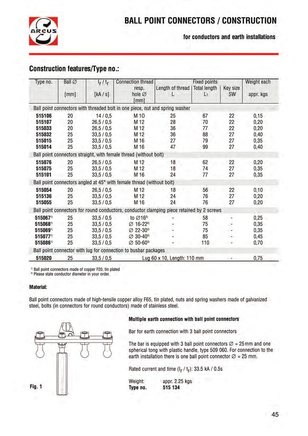
43 BALL POINT CONNECTORS / CONSTRUCTION for conductors and earth installations Advantages in use of fixed points: Defined connections to conductor and earth installation for earthing and short circuiting. The secure connection between fixed point and connection clamp guarantees safety in case of high dynamic and thermal loads during a short circuit. Ball thick The spherical heads of the fixed points are manufactured with a very high-quality surface. The threaded bolts are dimensioned for high dynamic forces. 44
44
45 PHASE CONNECTION CLAMPS FOR AL AND CU / CONSTRUCTION screw clamps for round conductors 46
46 PHASE CONNECTION CLAMPS FOR AL AND CU / CONSTRUCTION screw clamps especially for round conductors Type no. Clamping range Cable cross I r / t r Connection bolt Construction Weight each section max. thread [sqmm/mm] [sqmm] [ka / s] appr. kgs ) ,5 / 0,5 M 10 Compact construction, contact surfaces finely grooved ) ,5 / 0,5 M 10 High tensile sheet construction, 0.32 Flat 15 large contact surfaces, swivel spindle ) ,5 / 0,5 M 1O High tensile sheet construction, 0.55 Flat 20 large contact surfaces, swivel spindle ) ,5 / 0,5 M 1O Compact construction, also for 0.60 Flat 20 use with ball point connectors 20 mm and T-bolts 15 mm ) ,5 / 0,5 M 12 Compact construction, also for 0.80 Flat 20 use with ball point connectors 25 mm and T-bolts 20 mm ) ,5 / 0,5 M 12 High tensile sheet construction, 0.88 Flat 30 large contact surfaces, swivel spindle ) ,5 / 0,5 M 12 High tensile sheet construction, ) large contact surfaces, swivel 1.60 spindle ) / 0,5 M 12 Heavy section die cast ) ,5 / 0,5 M 12 Heavy section die cast ) ,5 / 0,5 M 12 Heavy section cast 1.30 aluminium alloy 1) Strap and pressure piece made of tin plated copper alloy, spindle galvanized steel 2) Heavy duty copper alloy, tin plated, type plain copper (only for copper conductors) 3) Tempered aluminium alloy, type , and spindle of galvanized steel 47
47 CONDUCTOR FIXED POINTS / CONSTRUCTION strap and shell form / made of copper or aluminium Advantages in the use of fixed points: Defined connections for earthing and short circuiting on conductor and earth installation The secure connection between fixed point and connection clamp guarantees safety in case of high dynamic and thermal loads during a short circuit. 48
48 CONDUCTOR FIXED POINTS strap and shell form / made of copper or aluminium Construction features / Type no. Cond.fixed point for cond. 1) Dimensions for phase for nominal Weight each type no. or of fixed point connection clamp voltage max. Material in mm appr. kgs Cu Al mm d l h type no. kv Cu Al Strap-type fixed points for round conductors parallel and transverse to the conductor ,80 0, , ) , , (fixed point not suitable - 1,10 for and ) ,20 Strap-type fixed points for round conductors transverse to the conductor ) ,50 0, ,70 Strap-type fixed points for round conductors parallel to the conductor ) ,50 0, ,70 0,70 Shell-type fixed points for round conductors ,35 Strap-type fixed points for flat conductors parallel and transverse to the conductor flach 12 3) ) 220 1,70 0, Strap-type fixed points for flat conductors parallel and transverse to the conductor flach80x ) ,30 0, Strap-type fixed points for 2 flat conductors parallel and transverse to the conductor max ) ,70-2 x 80 x ) ,50 1) Please state the exact conductor- in your order 2) Phase connection clamp only for use with copper fixed points 3) Attached by drilling two 8.5 mm holes, 40 mm between centres 4) Length of strap suitable for 2 phase connection clamps. Material: Cu: Straps made of copper and copper alloy (bare), bolts high-tensile copper alloy Al: Straps made of high tensile aluminium alloy, bolts of stainless steel 49
49 CONDUCTOR CONNECTION CLAMPS screwed clamps for flat conductors Fig. 1: Fig. 2: Fig. 3: Fig. 4: Construction features: Pointed clamps , : The clamping parts are closed by thightening the cone which is mounted on a threaded spindle. One clamping part has fine cross grooves, whilst the second one has a flat surface which is angled to correspond with the swinging action as the cone is tightening. Type has a stud in the serrated clamping part. The bus bar to be clamped should have a hole of appr. 6,5 mm to accomodate this stud. These clamps are especially designed for use on bus bars, flat switching contacts and disconnecting switches. Pointed clamps for contact blades type : This clamp is designed for use in encapsulated switchgear or on contacts with limited access space. The compact construction is a specific feature of this clamp. It can be used in a bushing with dimensions 50 x 36 cm. Pointed clamps are suitable for vertical or horizontal bus bars (e.g. on isolators). U-shaped clamp : This type is mounted at right angles on flat conductors. The contact surfaces in the strap are finely cross grooved. The pressure piece pivots on the threaded spindle so as to adapt to possible surface irregularities without affecting the contact. Type no. Clamping range Cable cross section I r / t r Connection bolt Weight each max. [mm] [sqmm] [ka / s] thread appr. kgs Pointed clamps flat up to ,5 / 0,5 M 1O 0, flat up to ,5 / 0,5 M 1O 0,50 with boring Contact blade ,5 / 0,5 M 10 0, U-shaped clamps flat up to ,5 / 0,5 M 10 0,50 Clamping parts and bolts are made of high tensile copper alloy. Application notes: In case of a short circuit dynamic forces are opposing the secure connection of the clamp to the conductor. For this reason ensure that the clamps are tightened properly. 50
50 EARTHING AND SHORT CIRCUITING DEVICES, EARTHING RODS for electric railway contact wires These devices are fully approved by the Deutsche Bahn / DB (German Railway System) Electrical load values for complete devices (according to the DB): I SW = 78 ka I k = 35.6 ka t k = 0.06 sec Fig Type no. Weight each clearing not clearing consisting of 1) appr. kgs track-profile track-profile for local storage , , , ,5 can be fitted on electrical track maintenance vans ,9 1) for parts please see page 53 Telescopic earthing rods in two sections with securable locking head. Insulating tubes made of fibre glass reinforced polyester, inner tube square. Rod head, coupling and rod end cap are made of metal. The robust construction is designed to withstand occasional dropping onto the track without damage. Telescopic earthing rod in three sections with securable locking head, insulated tubes made of fibre glass reinforced polyester. Due to its reduced transport length this rod is specially suitable for transport on electrical trains. Total length (Lg): 5.0 m Total length (Lg): 5.0 m Transport length (Lt): 2.9 m Transport length (Lt): 2.2 m Weight: appr. 5.5 kgs Weight: appr. 4.9 kgs Fig. 2 Type no.: Type no.: Fig. 3 51
51 EARTHING AND SHORT CIRCUITING DEVICES, FIXED POINTS EARTHING RODS for feeder cables and contact wires of electric railways These devices are fully approved by the Deutsche Bahn / DB (German Railway System) Fig Fig. 1: Fig. 3: The earthing and short circuiting device consists of: Phase connection clamp with test strip, for conductors 6-35 mm. Earthing and short circuiting cable cross section 50 sqmm, length 4000 mm, made of highly flexible copper lead with transparent insulation cover. Earth connection clamp with handle for ball point connectors 25 mm and flat conductors up to 20 mm. Weight appr kgs Type no Telescopic earthing rod in two sections with safety bayonet head, insulated tube made of fibre glass reinforced epoxy resin. Fixed points as required: Ball : 25 mm Thread: M16 x 47 Weight: appr kgs Type no Thread: M16 x 27 Weight: appr kgs Type no Multiple earth connection consisting of: Star point bar made of copper, with 2ball point connectors 25 mm fixed to an earth connection clamp for ball point connectors 25 mm. The multiple earth connection may be used with two single-phase short circuiting devices. Total length (Lg): Transport length (Lt): 3.5 m 1.9 m Weight: appr kgs Type no.: Weight: appr. 3.0 kgs Type no.: Fig. 4 52
52 COMPONENTS FOR EARTHING AND SHORT CIRCUITING DEVICES for contact wires of electric railways These devices are fully approved by the Deutsche Bahn / DB (German Railway System) Connection clamp for contact wires with spring plates and direct cable connection to the clamp body and pressure plate For grooved contact wires Ri to DIN and round contact wires 10.6 up to 13.2 mm. Weight: Type no.: appr kgs with flexible bayonet spindle with rigid bayonet spindle Suspension hook for earthing and short circuiting cables to obtain clearance-free fixing. Weight: appr. 0.2 kgs Type no.: Earthing and short circuiting cable red flags highly flexible multi-stranded copper lead 50 sqmm, length 8.5 m, with transparent and waterproof insulation cover, compression cable lug on both sides, with 3 red flags. Not for clearance-free earthing. Weight: appr. 5.4 kgs Type no.: / 068 Earthing and short circuiting cable as above, length 12 m. For clearance-free earthing. Weight: appr. 7.6 kgs Type no.: Rail foot earthing clamp with replaceable contact cutting piece for penetration of foreign matter. For rail profiles S 49, S 54, S 64, UIC Weight: Appr. 3.4 kgs Type no.: with hand screw Type no.: with ratchet 53

53 HIGH VOLTAGE LIVE LINE TESTERS AND EARTHING ROD, MULTI-SECTIONAL for contact wires of electric railways These devices are fully approved by the Deutsche Bahn / DB (German Railway System) Voltage tester ARCUSLIGHT for 15 KV, 16 2/3 Hz, with optical indication, self-testing device, glasfibre-reinforced epoxy resin tubes with rain shields. May be used in precipitation Supplied in a tough woven plastic carrying bag, cold-resistant. 2-section type for contact and reeder wires Total length (Lg): 4.6 m Transport length (Lt): 2.4 m Weight: appr. 3.1 kgs Type no.: section type with sealed screw-type couplings The reduced transport length makes his device ideal for fire brigades and emergency services. Total length (Lg): 4.6 m Transport length (Lt): appr.1 m Weight: appr. 3.5 kgs Type no.: section telescopic earthing rod with securable locking head, insulated fibre glass tubes, plug-in couplings with push-button locking. Due to its reduced transport length this rod is especially useful on board electric trains and emergency accident vehicles. Supplied in a tough woven plastic carrying bag, cold-resistant Total length (Lg): 5.0 m Transport length (Lt): appr m Weight: appr. 5.0 kgs Type no.: Fig. 1 Fig. 2:
54 SHORT CIRCUIT DEVICE FOR THIRD RAIL SYSTEMS This device is used for short circuiting tracks with a lateral contact rail. It is attached to the running rail adjacent to the contact rail. The short-circuit is effected by swinging over the fully insulated handle. The fast-operating system may be used in an emergency to short circuit the live contact rail. Short-circuit rating: Up to 30 ka/ s with 700 V d.c. The compact construction of the earthing device allows it to be stored under the train driver s seat. All electrical wearing parts are exchangeable. References: Munich, Berlin, Hamburg, Vienna, London Docklands, Prague, Singapore and others. Please state the distance A and B (between the rails), according to picture 2. Storage dimensions: Fig. 1 appr x 160 x 125 mm Weight: appr. 5.0 kgs Type no. for standard construction: Short circuit devices for other rail configurations on request. Fig. 2 55
55 DEVICES FOR THE DIVERSION OF INDUCTIVE CURRENTS These devices are designed to equalise for a short time differences in potentials. For this purpose the earthed test tip is brought in contact with the part to be restored to earth potential. The devices are firmly connected to the earthing rod: Construction: Earthing rod made of fibre glass reinforced epoxy resin tube, total length (L g ) = 1000 mm, firmly connected to test tip of aluminium. Earth cable 25 sqmm, length 3000 mm, with earth connection clamp Weight: appr. 1.8 kgs Type no.: As above, but earthing rod with a total length of 1500 mm. Weight: appr. 2.0 kgs Type no.: Fig Device for mounting to existing earthing rods: Construction: Test tip with screw-on quick fastening device to earthing rods , earth cable 25 sqmm, length 3000 mm, with earth connection clamp Weight: appr. 1.2 kgs Type no: For more information please see: Earthing rods page 63 Earth cables page 35 Earth connection clamps page 42 Fig
 Working on cable networks Working on insulated metal sheathed cables which are influenced by adjacent strong a.c. current paths, or by earth-fault currents of high voltage lines with a star neutral earth point is highly dangerous.")

56 JUMPER CONNECTION DEVICES for equalising induction cur rents in cables and pipelines Fig. 1: , Fig. 2: ) Working on cable networks Working on insulated metal sheathed cables which are influenced by adjacent strong a.c. current paths, or by earth-fault currents of high voltage lines with a star neutral earth point is highly dangerous. According to DIN VDE : , para , any insulated metal conductor under the electro-magnetic influence of an alternating current path, or a star neutral point of an h.v. network, must have a bridging electrical contact made of at least 16 sqmm before cutting. Our devices types and are especially designed for this application and have been proven in practice to be highly effective. Previous devices were either too heavy, caused deformations on the metal sheath of cables or worked loose during working. The ARCUS system fully overcomes these problems. 2.) Working on pipelines Before the separation of electrically conductive house connection pipelines and pipelines in buildings, e.g. when exchanging fittings, meters, or in case of repair works, a provisional electrical bypass with 25 sqmm can be applied. Jumper connection device type is also suitable for coated pipes. The clamps are connected by a highly flexible copper cable of 2500 mm length, with transparent insulation. Type no. Clamping range [mm] Construction features Weight per device Outer of the for bare and cable screen insulated pipes appr. kgs , Flexible tin plated conductor band, 1, stainless steel pressure spring, 1,10 plastic handles Pressure plate with circular grooves 3,7 of hardened burnished steel, hand screw, chain and threaded section 57

 with special stabilisation against ultraviolet light suitable for outside use.")
57 PLASTIC SAFETY HOOKS for rescue of accident victims S-shaped hook for the rescue of persons from l.v. current circuits, working machines, etc., for example by: pulling on arms, legs, arm pits, neck or ankle, etc. Material: Polyethylene-HD, highly heat-stable, good chemical resistivity. Technical Data: Density: 0,950 g/cm 3 Creep resistance: 600 V Breaking stretch: 300 % Bending e-module: 800 N/sqmm Pulling e-module >= 600 N/sqmm Bending stress: >= 15 N/sqmm Inflamability appr. 350 C Range of temperatures: Permanent use: -50 up to +70 C Fig. 1 1 kv safety hook ( ) with special stabilisation against ultraviolet light suitable for outside use. Do not store under direct solar radiation. Durability: For safety reasons the safety hook should be exchanged after 10 years. The year of production is marked on the hook. For low voltage up to 1 kv : Length: 1000 mm Bar diameter: 25 mm Colour: black Type no.: For high voltage up to 60 kv Length: 1530 mm Bar diameter: 35 mm Colour: ivory Type no.: Fig. 2 58

58 ELECTRICAL SAFETY GLOVES made of latex Application: Insulated safety gloves are suitable for live working up to 500 V. They conform to DIN EN 60903, VDE 0682 part 311 of October Material: Special natural latex with good properties against tearing and abrasion and very good cold flexibility. Resistant against acid and ozone. Shape and properties: Fig. 1 Type no. Class Size Length Strength appr.[mm] appr. [mm] ,5 Anatomical shape with good flexibility and good touching sensitivity. Long-term skin protection due to antibacterial treatment. 59

59 TECHNICAL INFORMATION earthing rods Earthing rods Earthing rods are used for the approach and connection of phase clamps to dead conductors. Earthing rods are divided by the black ring into the insulating section Li and the handle section Lh. The length of the insulating section is 500 mm and is independent of the nominal voltage of the switchgear in which the earthing rod is to be used. The length L 0 of an earthing rod is mainly not determined by the insulating properties but by the condition to keep the operator at the necessary distance from live parts of the installation. Phase clamp Conductor connection If the total length L 0 required for earthing and short circuiting is inconvenient for transport and storage, the use of telescopic or multi-sectional types is recommended. Also the weight of the earthing rod together with the earthing and short circuiting device to be directed safely to the line influences the bending strength and flexibility of the earthing rods made of fibre glass reinforced epoxy resin. To EN 61230: they are divided into three cathegories: Black ring light (L) bending strength 25 N, normal (S) bending strength 50 N, reinforced (R) bending strength 100 N. This definition replaces the weight information on the type labels of the rods to the old standard. In the chapter earthing rods in this brochure (from page 63 on) you will find a large number of long-term approved earthing rods which fulfill all present demands. From now on the labels on the earthing rods will show the marking according to the new European Standard, as the example below: Black ring Earthing Rod Type Follow the instruction for use! Fig. 2: Example of a label to IEC 1230 Fig. 1: Telescopic earthing rod 60
 Protection with bayonet slot against accidental loosening.")
60 TECHNICAL INFORMATION Coupling heads for earthing and operating rods 1) The working heads shown below are suitable for use with phase clamps, switching rod heads and other operating equipment with a spindle according to DIN A special feature of these heads is their fast and simple operation. Normal bayonet head (Fig. 1) Protection with bayonet slot against accidental loosening. Material: Impact resistant plastic material. Fig. 1 Fig. 2 Fig. 3 Spring bayonet head (Fig. 2) Protection against accidental loosening in addition with a spring. Material: Safety rod head (Fig. 3) 1) Impact resistant plastic material Elastomere spring A plastic head which can be turned around a steel bayonet equipped with a spring control device prevents accidental loosening or detachment of the phase clamp. Material: Impact resistant plastic material steel parts galvanized Safety bayonet head with locking function (Fig. 4) 1) The function is the same as with the safety bayonet head. In addition the head can be locked by a threaded nut. This robust head is intended for rough handling as with railways or mining. Material: All parts metal steel parts galvanized Fig. 4 Safety joint head (Fig. 5) 1) Construction as the safety bayonet head, but in addition with a steel joint and threaded ring to allow the head to swivel to all sides at an angle of 45. Material: Impact resistant plastic material steel parts galvanized Fig. 5 Connection piece (Fig. 6) For a non-detachable connection between insulated rod and phase clamp. Material: Impact resistant plastic material 1) Due to the metal parts the safety bayonet heads may only be used with operating rods under certain conditions. Fig. 6 61
61 TECHNICAL INFORMATION Rod connections for multi-sectional earthing and operating rods Connection with slotted sleeve for telescopic rods (Fig. 1) The inner rod is to be fully extended and is clamped into a slotted sleeve secured against torsion. The clamp screw is nondetachable. Material: Sleeve and grip screw made of plastic material, bolted screw made of galvanized steel. Fig. 1 Clamping connection for telescopic rod type (Fig. 2 ) The inner rod can be fully extended up to the stop position and secured against torsion and tensile forces with the tightening strap and pressure screw. All parts are covered with shock resistant material. This clamping connection is suitable for earthing rods for use under rough conditions (railway tracks, mining). Material: Hand knob of aluminium, all other parts of galvanized steel. Fig. 2 Locking connection for telescopic rods (Fig. 3) Once the locking ring is slackened, the inner rod can be telescoped between 0,4 and 0,5 mtrs, and then locked to ensure it can neither rotate nor extend. The locking function is assisted by a spring. This feature enables different operating lengths to be safely achieved. locked position unlocked position Material: Locking pin and spring stainless steel. Joint parts made of impact-resistant plastic material. Fig. 3 Locking Ring Plug-in connection for multi-section rods (Fig. 4) To connect separate rods these are inserted and locked by means of the locking ring, to secure against torsion and tensile forces. Foamed tubes with rain shields and multi-sectional operating rods for use in precipitation can be manufactured if required (see page 69). Material: Locking pin and spring stainless steel, joint parts made of impact-resistant plastic material. Fig. 4 Locking Ring 62
62 SINGLE SECTION EARTHING RODS for nominal voltages above 1 kv Coupling heads / construction: Fig. 2 Single section earthing rods Dimensions L G [mm] L H [mm] D[mm] Rod category (VDE 0683 P a rt 1OO) R R S S R S L Weight 5 ) [kgs / each] 0, 8 1, 0 0, 9 1, 1 2, 0 2, 5 3, 1 Construction with coupling head Type no. A normal bayonet head B spring bayonet head C safety rod head D connection piece 1 ) F safety joint head ) Please state type of phase clamp (page 47, 48) in your order. 2) Upon request the rod can be supplied with a hand protection disk instead of the black ring. 3) Label made of PVC, colour yellow, with abrasion resistant printing. 4) Rod end made of non-slip rubber with holes against condensation water. 5) The stated weights refer to those rods with safety rod head. Material: Rods made of fibre glass reinforced epoxy resin, colour yellow, rod heads impact-resistant plastic material. For earthing rod details please see pages Fig. 1 63
 R R S S L Weight")
63 TWO- AND THREE-SECTION TELESCOPIC EARTHING RODS with slotted sleeves for nominal voltages above 1 kv Coupling heads / construction: Telescopic earthing rods with slotted sleeves two-section type Dimensions L G [mm] L H [mm] L T [mm] D/d [mm] 40/30 40/30 40/30 40/30 40/30 Rod category (VDE 0683 Part 100) R R S S L Weight 4) [kgs/each] 0,90 1,15 1,50 1,90 2,30 Construction with coupling head Type no. A Normal bayonet head B Spring bayonet head C Safety rod head Dimensions L G [mm] L H [mm] L T [mm] D/d 1 /d [mm] 50 / 40/30 50 / 40/30 Rod category (VDE 0683 Part 1OO) Weight 4) [kgs/each] 2,20 2,80 S three-section type Construction with coupling head Type no. A Normal bayonet head B Spring bayonet head C Safety rod head ) Upon request the rod can be supplied with a hand protection disk instead of the black ring. 2) Label made of PVC, colour yellow, with abrasion resistant printing. 3) Rod end made of non-slip rubber with holes against condensation water. 4) The stated weights refer to those rods with safety rod head. L Fig. 2 Material: Rods made of fibre glass reinforced epoxy resin, colour yellow, rod heads impact-resistant plastic material. Fig. 1 For earthing rod details please see pages
 R R S S L Weight")
64 TWO- AND THREE-SECTION TELESCOPIC EARTHING RODS with locking connection for nominal voltages above 1 kv Coupling heads / construction: Telescopic earthing rods with slotted sleeves two-section type Dimensions L G [mm] L H [mm] L T [mm] D/d [mm] 40/30 40/30 40/30 40/30 40/30 Rod category (VDE 0683 Part 100) R R S S L Weight 4) [kgs/each] 0,90 1,20 1,50 1,90 2,30 Construction with coupling head Type no. A Normal bayonet head B Spring bayonet head C Safety rod head D Connection piece Dimensions L G [mm] L H [mm] L T [mm] D/d 1 /d [mm] 50/ 40/30 50/ 40/ 30 Rod category (VDE 0683 Part 1OO) Weight 4) [kgs/each] 2,20 2,80 S L three-section type Construction with coupling head Type no. A Normal bayonet head B Spring bayonet head C Safety rod head D Connection piece 1) Fig. 2 1) Please state type of phase clamp (page 47, 48) in your order. 2) Upon request the rod can be supplied with a hand protection disk instead of the black ring. 3) Label made of PVC, colour yellow, with abrasion resistant printing. 4) Rod end made of non-slip rubber with holes against condensation water. 5) The stated weights refer to those rods with safety rod head. Fig. 1 Material: Rods made of fibre glass reinforced epoxy resin, colour yellow, rod heads impact-resistant plastic material. For earthing rod details please see pages
 Fig.")
65 MULTI-SECTION EARTHING RODS, PLUG-IN TYPE for nominal voltages above 1 kv Coupling heads / construction: Multi-section earthing rods, plug-in type Construction 2-sect. 3-sect. Dimensions L G [mm] L H [mm] L T [mm] D/d [mm] 40/ 30 40/40/ 30 Rod category (VDE 0683 Part 100) Fig. 2 Weight 4) [kgs/each] 3,00 3,60 Construction with coupling head Type no. A Normal bayonet head B Spring bayonet head C Safety rod head S L 1) Upon request the rod can be supplied with a hand protection disk instead of the black ring. 2) Label made of PVC, colour yellow, with abrasion resistant printing. 3) Rod end made of non-slip rubber with holes against condensation water. 4) The stated weights refer to those rods with safety rod head. Material: Rods made of fibre glass reinforced epoxy resin, colour yellow, rod heads impact-resistant plastic material. For earthing rod details please see pages Fig. 1 66
66 TECHNICAL EXPLANATION Operating rods for nominal voltages above 1 kv Operating rods Operating rods are devices for manual use for testing and operating live parts. Construction of rods is as follows: VDE standards: Fig. 1 1 Operating head 7 Rod end cap 2 Red ring L V Length of the extension section 3 Insulating section (length L I ) L O Length of the top section 4 Label with type indication L G Total length of the operating rod 5 Hand protection disk L I Length of the insulating section 6 Length of handle (L H ) Between the hand protection disk and the Red ring the insulating section (L I ) is located which gives the operator the protective distance and sufficient length of insulation for safe handling. The minimum length of the insulating section is between 500 and 3200 mm and depends on the nominal voltage for which the operating rod is marked on the label. Discharge currents must not exceed 0.2 ma in dry conditions and 0.5 ma under precipitation. The top section (L O ) is the rod section between the insulating section and upper end of the operating head. The extension section (L V ) is located between the insulating section and the operating element. It enables the operator to reach distant parts of the installation. In this case it is permitted to reach with the operating head along live installation parts. Operating rods are manufactured in 2 categories: 1.) For indoor and outdoor use but not with precipitation. Label is marked: Do not use with precipitation!. 2.) For use indoors and outdoors with any kind of weather. Label is marked: May be used in precipitation. DIN VDE 0681 part 1: DIN part 2/ VDE 0681 part 2: DIN part 3/ VDE 0681 part 3: DIN VDE 0681 part 4: Operating, testing and safe-guarding devices for work on electrically energised systems with rated voltages exceeding 1 kv - Part 1: General requirements for the part 2 to 4 VDE-specification for operating, testing and safe-guarding devices used when carrying out live-line-work on equipment with rated voltages exceeding 1 kv - Part 2: Operating rods - Part 3: Fuse tongs Operating, testing and safe-guarding devices for work on electrically energised systems with rated voltages exceeding 1 kv - Part 4: AC voltage detectors The operating rods shown on the following pages are according to part 1 to 3 of the afore mentioned standards. High voltage live line testers to VDE 0682 part 411 are described in a separate brochure. 67
67 SINGLE SECTION OPERATING RODS SWITCHING ROD HEAD Operating rods for nominal voltages above 1 kv not to be used with precipitation Construction and material: Operating rods comply with DIN VDE 0681 part 1 / They are equipped with a normal bayonet head as described on page 61. The rods are manufactured from fibre glass reinforced and smooth epoxy resin tubes. The surface is protected by a yellow UV-resistant varnish. The hand protection disk is made of black rubber material. The rod end is sealed with a non-slip rubber cap. Labels are made of PVC-material, colour yellow, with abrasion resistant printing. Single section operating rods Nominal voltage up to 30 up to 60 up to 110 up to 150 4) up to 220 4) up to 380 4) L G [mm] L H [mm] L I [mm] D [mm] Weight [kg/each] 0,60 0,70 0,90 1,80 2,30 3,0 Type no ) Red Ring 2) Label 3) Rod end cap 4) Only for networks with effectively earthed star point. Switching rod head To DIN part 2 / 3.77, can be quickly screwed onto the operating rod. Material: Fibre glass reinforced polyamide, operating bolt made of solid glass polyester. Type no.: Fig. 2 For further details about operating rods please see pages 61, 62 and 67. The -test marks on this page were granted by the VDE Test Office. 68

68 SINGLE- AND MULTI-SECTION OPERATING RODS, PLUG-IN TYPE for nominal voltages above 1 kv Can also be used with precipitation Construction and material: Operating rods comply with DIN VDE 0681 part 1 / and are equipped with a normal bayonet head as described on page 61. The rods are manufactured from fibre glass reinforced and smoothened epoxy resin tubes. The surface is protected by a yellow UV-resistant varnish. The inner tube is foamed with dense pores. The hand protection disk is made of black rubber material. The rod end is sealed with a non-slip rubber cap. Labels are made of PVC-material, colour yellow, with abrasion resistant printing. The rain insulators are made of impact-resistant plastic material, colour blue, and are glued to the tube unmovably. For further details about operating rods please see pages 61, 62 and 67. Operating rods Construction one-sectional two-section three-section plugged-in type plugged-in type Nominal voltage[kv] up to 30 up to 60 up to 110 up to 110 up to 150 4) up to 220 4) L G [mm] L H [mm] L T [mm] L I [mm] D/D/d [mm] /30 40/30 40/40/30 Weight [kg/each] 2,0 2,4 2,8 3,0 3,5 4,0 Type-no ) Red Ring 2) Label 3) Rod end cap 4) Only for networks with effectively earthed star point. 69
69 SWITCHING RODS for nominal voltages 10 kv to 110 kv Must not be used in precipitation Construction and material: Switching rods comply with DIN VDE 0681 part 2 / Operating bolt and switching rod heads are made of high-quality plastic material. The rods are manufactured from fibre glass reinforced and smoothened epoxy resin tubes. The surface is protected by a yellow UV-resistant varnish. The hand protection disk is made of black rubber material. The rod end is sealed with a non-slip rubber cap. Labels are made of PVC-material, colour yellow, with special printing. Switching rods Nominal up to 30 up to 30 up to 30 up to 30 up to 30 up to 30 up to 30 voltage [kv] L G [mm] L H [mm] L I [mm] D [mm] Weight 0,60 0,70 0,90 1,10 1,30 1,50 1,90 [kg/each] Type no Switching rods Nominal up to 60 up to 110 voltage [kv] L G [mm] L H [mm] L I [mm] D [mm] Weight 0,70 0,90 [kg/each] Type no ) Red Ring 2) Label 3) Rod end cap For further details about switching rods and operating rods please see page 67. Fig. 1 The -test marks on this page were granted by the VDE Test Office. 70
70 FUSE TONGS for nominal voltages 10 kv to 30 kv not to be used with precipitation The fuse tong is used to grip an HRC-fuse from the front. By rotating the handle the HRC-fuse is held tightly by the clamping part. Little space is required by the fuse tong on each side. It is highly suitable for use in switching stations where space is limited. Type no. UN LH LI Safety [kv] [mm] [mm] standard Clamping range: Weight each: mm appr. 2 kgs Material: Clamping head made of fibre glass reinforced plastic material, colour black. Insulating tube fibre glass reinforced polyester, colour yellow. Hand protection disk made of hardened rubber, colour black. Label made of plastic material, with abrasion resistant printing, colour yellow. The -test signs on this page were granted by the Technical Supervision Association (TÜV) Bavaria. 1) Red Ring 2) Label Fig. 1 71
71 72 NOTES
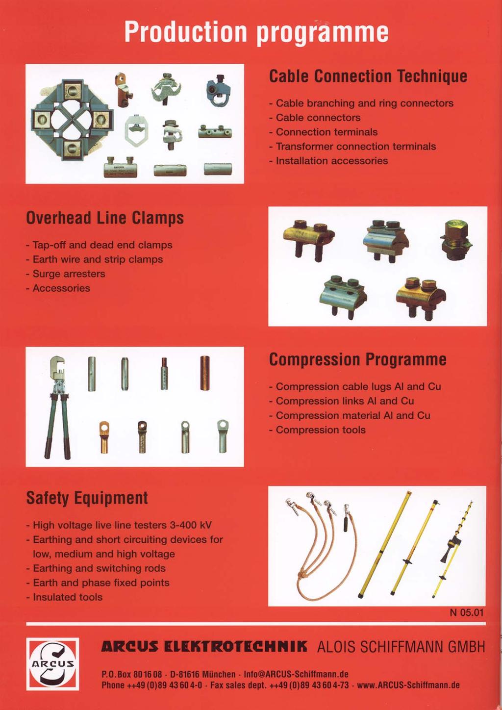
72
TECHNICAL INFORMATION. Dipl.-Ing. (FH) Christian Niklis. Stationary Lance Earthing Device
 Christian Niklis. Stationary Lance Earthing Device") TECHNICAL INFORMATION Dipl.-Ing. (FH) Christian Niklis Stationary Lance Earthing Device GENERAL Lance earthing devices - What s s the use of them? Short-circuit-proof earthing in high voltage substations
TECHNICAL INFORMATION Dipl.-Ing. (FH) Christian Niklis Stationary Lance Earthing Device GENERAL Lance earthing devices - What s s the use of them? Short-circuit-proof earthing in high voltage substations
TEMPORARY ELECTRIC WIRING FOR CARNIVALS, CONVENTIONS, EXHIBITIONS, FAIRS AND SIMILAR USES
 INFORMATION BULLETIN / PUBLIC - ELECTRICAL CODE REFERENCE NO.: LAMC 93.0230 Effective: 3-24-69 DOCUMENT NO. P/EC 2002-006 Revised: 11-17-00 Previously Issued As: RGA #7-69 TEMPORARY ELECTRIC WIRING FOR
TABLE OF CONTENTS FOREWORD...3 INTRODUCTION SCOPE NORMATIVE REFERENCES DEFINITIONS AND ABBREVIATIONS REQUIREMENTS...
 TITLE SPECIFICATION FOR PORTABLE DATE: JULY 2006 PAGE: 1 OF 25 TABLE OF CONTENTS Page FOREWORD...3 INTRODUCTION...4 1 SCOPE...4 2 NORMATIVE S...4 3 DEFINITIONS AND ABBIATIONS...4 4 REQUIREMENTS...5 4.1
Item Code Description Unit Qty Total
 UNDP ELECTRICITY SECTOR NORTHERN GOVERNORATES Phase XI Item Code Description Unit Qty Total 04-02-00001 Service Pole - 6m, 75mm dia GS Pipe 11250 04-02-00002 9m Tubular Steel Poles complete with all Accessories
Corporate Standard 0001/MUC_EN Protective Conductor Connection
 Corporate Standard 0001/MUCEN 1 History Version Valid from Author Modification 1st July 2008 K. Wianski / A.Triebe First edition 2 Scope of Application This corporate standard shall apply to combinations
INTRODUCTION. The plug-in connection on the cables and lightning arrestors, allows for easy installation and replacement.
 INTRODUCTION The Power Systems 44 kv MiniSub TM is the most compact system at this voltage available. Utilizing a deadfront termination and lightning arrestor setup, it eliminates the line top or side
Type SIMOPRIME A4, up to 24 kv, Air-Insulated Medium-Voltage Switchgear
 Circuit-Breaker www.siemens.com/energy Switchgear Type SIMOPRIME A4, up to 24 kv, Air-Insulated Medium-Voltage Switchgear s Technology Circuit-Breaker Switchgear Type SIMOPRIME, up to 17.5 kv, Air-Insulated
SAFETY EQUIPMENT Safety Equipment for Railway Systems
 Product Catalogue SAFETY EQUIPMENT Safety Equipment for Railway Systems Information concerning this catalogue: All rights reserved for copying of any kind. All dimensions and pictures are not binding.
24 k B788 ELEKTROTECHNISCHE WERKE FRITZ DRIESCHER & SÖHNE GMBH
 788 Instructions for Installation, Operation and Maintenance for DRIESCHER - Air - Insulated Medium - Voltage Compact Switchgears for Substations Rated voltage 12 kv and 24 kv Rated current 630 A 24 k
NXPLUS C Single busbar. Maintenance-free for lifetime
 NXPLUS C Single busbar Maintenance-free for lifetime Energy Distribution Welcome! Page 2 Content Overview Technical data Typicals Panel design Circuit-Breaker panel Busbar Operation Metering Low-voltage
CLP POWER HONG KONG LIMITED. SUPPLY RULES March 2001
 CLP POWER HONG KONG LIMITED SUPPLY March 2001 ADVISORY SERVICE Advice concerning matters relating to the supply of electricity may be obtained free of charge from the Company. OTHER COMPANY PUBLICATIONS
AFTER GAZETTING (WORKING DOCUMENT FOR A 3 YEAR PERIOD) DATE PAGE PARAGRAPH DESCRIPTION ORIGINATOR APPROVED
 DATE PAGE PARAGRAPH DESCRIPTION ORIGINATOR APPROVED") PART B-07 TITLE: SERVICE CONNECTIONS SPECIFICTION NO: B-07 INCEPTION DATE: AFTER GAZETTING (WORKING DOCUMENT FOR A 3 YEAR PERIOD) AMENDMENTS / REVISIONS DATE PAGE PARAGRAPH DESCRIPTION ORIGINATOR APPROVED
PART B-07 TITLE: SERVICE CONNECTIONS SPECIFICTION NO: B-07 INCEPTION DATE: AFTER GAZETTING (WORKING DOCUMENT FOR A 3 YEAR PERIOD) AMENDMENTS / REVISIONS DATE PAGE PARAGRAPH DESCRIPTION ORIGINATOR APPROVED
Overhead transmission lines Spacers
 = SVENSKA KRAFTNÄT SWEDISH NATIONAL GRID UNIT, BUSINESS AREA AEL, Asset Management Lines OUR REFERENCE TR05-08E DATE 2016-06-09 CONSU12TATIONS TECHNICAL GUIDELINE REVISION 3 APPROVED Overhead transmission
EDITION 2011/2012 SAFETY EQUIPMENT
 EDITION 2011/2012 SAFETY EQUIPMENT Product catalogue The Standard in Matters of Safety. PFISTERER. When work is to be carried out on electrical installations, the safety of personnel, materials and system
Design specifications
 Design specifications Design To relevant standards: IEC, VDE, DIN, ISO, EN With squirrel-cage or slipring rotor Degree of protection IP 55 / IP 65 Cooling method IC511, suitable for both indoor and outdoor
Volume-III : Section-I 370 Technical Specifications
 Volume-III : Section-I 370 TECHNICAL SPECIFICATION-PIERCING INSULATOR 5.1 Insulation Piercing Connectors (IPC) 5.1.1 Insulation Piercing Connectors (IPC) are used for making Tee/Tap-off/Service connectors
Benefits, typical uses
 R-HA26-013. eps Switchgear Type 8BT1, up to 24kV,Air-Insulated Contents Application Page Application Benefits 2 Typical uses 2 and 3 Technical Data Ratings 4 Classification, dimensions, 5 room planning
SAFETY EQUIPMENT FOR RAILWAYS
 SAFETY EQUIPMENT FOR RAILWAYS Safety Equipment for Railways Our product range of safety equipment for railways is listed separately in Publication No. DS 501/E. The devices shown are compatible to systems
Product Catalogue. SAFETY EQUIPMENT for Railway Systems
 Product Catalogue SAFETY EQUIPMENT for Railway Systems 8 Your Partner for Safety Equipment Since 1928 the name ARCUS equals quality and reliability in cable connections and safety products. The ARCUS ELEKTROTECHNIK
Switchgear Type 8BT1, up to 24 kv, air-insulated. Medium Voltage Switchgear Catalog HA 26.
 www.siemens.com/medium-voltage-switchgear Switchgear Type 8BT1, up to 24 kv, air-insulated Medium Voltage Switchgear Catalog HA 26.31 2012 Answers for infrastructure and cities. R-HA26-013. eps Contents
Circuit-Breaker Switchgear Type SIMOPRIME, up to 17.5 kv, Air-Insulated Medium-Voltage Switchgear.
 Circuit-Breaker Switchgear Type SIMOPRIME, up to 17.5 kv, Air-Insulated Medium-Voltage Switchgear www.siemens.com/energy Technology s Contents Application Page Benefits 2 Typical uses 2 and 3 Technical
STANDARD SPECIFICATION FOR. LIGHTING AND DC DISTRIBUTION PANELS WITH MCBs DOCUMENT NO: 44LK-5100/E.02/011
 Page 1 of 6 STANDARD SPECIFICATION FOR LIGHTING AND DC DISTRIBUTION PANELS WITH MCBs Rev No. Issue Date Pages Rev Description Prepared By Checked By Approved By 0 15.07.2008 6 Issued for FEED MSJ VDV VDV
045 : 2000 CEB STANDARD
 045 : 2000 CEB STANDARD LOW VOLTAGE FUSE SWITCH DISCONNECTOR CEYLON ELECTRICITY BOARD SRI LANKA Specification for LOW VOLTAGE FUSE SWITCH DISCONNECTOR CEB Standard 045 : 2000 CEYLON ELECTRICITY BOARD No.
MR - MEDIUM RATING A
 88 MR - MEDIUM RATING 160-1000A SECTION CONTENTS 90 General features 96 Advantages 100 Illustrated contents MR MEDIUM RATING 102 Trunking components 110 Feed units and end covers 113 Tap-off boxes 118
LIST OF EDD DESCRIPTION/ SPECIFICATION AS 19 TH OCTOBER 2016
 No Description/ Specification Amendment 1 EDD 1 :2008 11/0.415 kv Distribution Transformer, Oil Filled - 2 ED 2 :1987 The Galvanization of Iron and Steel, Articles Other Than Steel Wire - 3 ED 3 :1979
1 Product Description System Layout Safety Instructions Intended Use Installation... 3
 Order Number 0812xx- Contents 1 Product Description... 2 2 System Layout... 2 3 Safety Instructions... 3 4 Intended Use... 3 5 Installation... 3 5.1 Hanger Clamp... 3 5.2 Cutting of Conductor Rail... 4
with Vacuum Circuit Breaker HAF
 M E T A L - C L A D S W I T C H G E A R Safety and Reliability with Vacuum Circuit Breaker HAF Flexible Design and Compact with Vacuum Circuit Breaker HVF Easy Installation and Maintenance We build a better
2013 JEAN MÜLLER Products
 2013 JEAN MÜLLER Products Company JEAN MÜLLER JEAN MÜLLER was founded in 1897 in Germany, when the applications of electricity were still in their very early days. The company chose as its basic activity
Installation and Operating Instruction for Brake Caliper HW 150 HFA and HW 180 HFA E e
 Installation and Operating Instruction for Brake Caliper HW 150 HFA and HW 180 HFA E 09.736e Schaberweg 30-38 Phone +49 6172 275-0 61348 Bad Homburg Fax +49 6172 275-275 Germany www.ringspann.com info@ringspann.com
HV DIN FUSE-LINKS FOR TRANSFORMER PROTECTION. March 2017
 HV DIN FUSE-LINKS FOR TRANSFORMER PROTECTION March 2017 HV FUSE-LINKS IN THE WORLD UL STANDARD E OR R RATED: AMERICAN STANDARD DIN STANDARD: GERMAN STANDARD FR STANDARD: FRENCH STANDARD BS STANDARD: BRITISH
1ZSC AAA en, Rev. 6. Resin impregnated paper bushing, oil to SF 6., type GSBK Technical guide
 1ZSC563-AAA en, Rev. 6 Resin impregnated paper bushing, oil to SF 6, type GSBK Technical guide Original instruction The information provided in this document is intended to be general and does not cover
013 : 2009 CEB SPECIFICATION MOULDED CASE CIRCUIT BREAKERS
 013 : 2009 CEB SPECIFICATION MOULDED CASE CIRCUIT BREAKERS FOR OVERHEAD NETWOKS CEYLON ELECTRICITY BOARD SRI LANKA Specification for MOULDED CASE CIRCUIT BREAKERS FOR OVERHEAD NETWOKS CEB Specification
AIR INSULATED EXTENDABLE SWITCHGEAR UP TO 12KV GUIDE
 AIR INSULATED EXTENDABLE SWITCHGEAR UP TO 12KV GUIDE Certificate Number FM35831 APPLICATION Typical Uses and Classification The MSGair switchgear is used in transformer and switching substations mainly
FUSES. Safety through quality
 Safety through quality HH HIGH VOLTAGE Over many decades SIBA has developed a global product line of High Voltage Fuses that are comprehensive for any and all applications. Superior engineering, advanced
Instruction manual. EK6 Earthing switch 36/40.5 kv
 Instruction manual EK6 Earthing switch 36/40.5 kv Your safety first always! That s why our instruction manual begins with these recommendations: Only install switchgear and/or switchboards in enclosed
CONNECTORS AND FITTINGS
 Industry photo: should be a the same image as larger industry photo. Either a different crop or different angle. Human photo. Can be environmental/ documentaty style or portrait of engineer. Human photo.
Caledonian Medium Voltage Cables Three Core Cables to VDE 0276-
 Three Core Cables to VDE 0276 APPLICATIONS The three core cables are designed for distribution of electrical power with nominal voltage Uo/U ranging from 3.6/6.6KV to 19/33KV and frequency 50Hz. They are
Mechanical Connectors, Lugs and Repair Sleeves for Medium Voltage Cable Accessories up to 42 kv
 Mechanical Connectors, Lugs and Repair Sleeves for Medium Voltage Cable Accessories up to 42 kv Mechanical Connectors, Lugs and Repair Sleeves for Medium Voltage Cable Accessories up to 42 kv Features
CORDAFLEX(SMK) (N)SHTÖU Tough Rubber-Sheathed Reeling Cables
 (N)SHTÖU Tough Rubber-Sheathed Reeling Cables") CORDAFLEX(SMK) (N)SHTÖU Tough Rubber-Sheathed Reeling Cables 3 SK1_1-001.tif 4 SK1_1-003.tif SK1_1-00.tif Selection and dimensioning criteria Refer to Section 4 for further details Ü Type CORDAFLEX(SMK)
CORDAFLEX(SMK) (N)SHTÖU Tough Rubber-Sheathed Reeling Cables 3 SK1_1-001.tif 4 SK1_1-003.tif SK1_1-00.tif Selection and dimensioning criteria Refer to Section 4 for further details Ü Type CORDAFLEX(SMK)
31-SDMS-02 REV. 01 SPECIFICATIONS FOR
 31-SDMS-02 REV. 01 SPECIFICATIONS FOR LOW VOLTAGE DISTRIBUTION PILLAR This specification is property of SEC and subject to change or modification without any notice C O N T E N T S S. NO. D E S C R I P
sa B-CABLES nv PROTOLON(ST) NTSCGEWOEU.../3E Medium Voltage Flexible Cables for Use in Water with Copper Core Shield sa B-CABLES nv ENERGY
 NTSCGEWOEU.../3E Medium Voltage Flexible Cables for Use in Water with Copper Core Shield sa B-CABLES nv ENERGY") PROTOLON(ST) NTSCGEWOEU.../3E Medium Voltage Flexible Cables for Use in Water with Copper Core Shield ENERGY Technical Data Electrical Thermal Type Type designation PROTOLON (ST) NTSCGECEWÖU.../3E Approvals/
PROTOLON(ST) NTSCGEWOEU.../3E Medium Voltage Flexible Cables for Use in Water with Copper Core Shield ENERGY Technical Data Electrical Thermal Type Type designation PROTOLON (ST) NTSCGECEWÖU.../3E Approvals/
Disconnectors and earthing switches up to 25 kv AC
 Disconnectors and earthing switches up to 25 kv AC Sicat 8WL6144 for overhead contact line systems in main-line railways siemens.com/rail-electrification The disconnectors and earthing switches of the
CABLE SYSTEMS. Accessories and Systems for Medium and High-Voltage Cables up to 300 kv.
 MV-CONNEX, HV-CONNEX, IXOSIL Terminations, IXOSIL MSA Slip-on Joint Boxes CABLE SYSTEMS Accessories and Systems for Medium and High-Voltage Cables up to 300 kv. Welcome to the CABLE SYSTEMS Centre of Competence.
1ZSC AAA EN, REV. 7. Transformer bushings type GSBK Technical guide
 1ZSC563-AAA EN, REV. 7 Transformer bushings type GSBK Technical guide Original instruction The information provided in this document is intended to be general and does not cover all possible applications.
vertical fuse switch disconnectors
 SWITCHGEAR ARS vertical fuse switch disconnectors - touch protection IP 30 from the front - fibre glass extra strenghtened, self extinguishing thermoplastics - double clearance between open contacts -
Assembly and Operating Instructions
 A35AE FU...A150AE FU en Assembly and Operating Instructions Plug-in drives Important information for: Fitters / Electricians / Users Please forward accordingly! These instructions must be kept safe for
sa B-CABLES nv PROTOLON(ST) NTSCGEWOEU Medium Voltage Flexible Cables for Use In Water sa B-CABLES nv ENERGY
 NTSCGEWOEU Medium Voltage Flexible Cables for Use In Water sa B-CABLES nv ENERGY") PROTOLON(ST) NTSCGEWOEU Medium Voltage Flexible Cables for Use In Water ENERGY Technical Data Electrical Thermal Type Type designation PROTOLON(ST) NTSCGEWÖU Approvals/ standards DIN VDE 0250 part 813
PROTOLON(ST) NTSCGEWOEU Medium Voltage Flexible Cables for Use In Water ENERGY Technical Data Electrical Thermal Type Type designation PROTOLON(ST) NTSCGEWÖU Approvals/ standards DIN VDE 0250 part 813
Transformer Bushing Type EKTO
 Transformer Bushing Type EKTO Mounting Operating and Maintenance Instructions Operating Instructions BAL EKTO/04e Visum 01/14 T/gue Page 1 of 16 SAFETY INSTRUCTIONS These instructions are valid for mounting,
SLOVAK UNIVERSITY OF TECHNOLOGY Faculty of Material Science and Technology in Trnava ELECTRICAL ENGINEERING AND ELECTRONICS.
 SLOVAK UNIVERSITY OF TECHNOLOGY Faculty of Material Science and Technology in Trnava ELECTRICAL ENGINEERING AND ELECTRONICS Róbert Riedlmajer TRNAVA 2007 Unit 14 - Fundamentals of power system protection
Urgent Support to the Agriculture and Electricity Sector in the Gaza Strip
 Project Number: PAL -10-00063805 Project Name: Urgent Support to the Agriculture and Electricity Sector in the Gaza Strip Bill of Quantities Package # 2 LOT 2: Supply of Electrical Materials The contract
B kv Gas-insulated Substations
 72.5 145 kv Gas-insulated Substations The increasing demand for electrical power in cities and industrial centres requires the installation of a compact and efficient distribution and transmission network.
Nexans WINDLINK connection system. Nexans Power Accessories Germany GmbH
 Nexans WINDLINK connection system Nexans Power Accessies Germany GmbH Technical instructions and application infmation Reprinting, even partial, only with special allowance. The data given were determined
AF series contactors (9 2650)
") R E32527 R E39322 contactors General purpose and motor applications AF series contactors (9 2650) 3- & 4-pole contactors General purpose up to 2700 A Motor applications up to 50 hp, 900 kw NEMA Sizes 00
R E32527 R E39322 contactors General purpose and motor applications AF series contactors (9 2650) 3- & 4-pole contactors General purpose up to 2700 A Motor applications up to 50 hp, 900 kw NEMA Sizes 00
Moisture-proof cable branch boxes Ceiling distribution boxes Lamp suspension boxes Wall boxes Concrete wall boxes and accessories
 Branch and lustre terminals Apparatus and light terminals Porcelain terminals Screwless terminals Flat plug terminals Flat plug branch terminals Mains branch terminals Connection terminals Earthed wire
MATERIAL FOR FIBRE OPTIC LINES. General C-bracket HSU trunnion type, forged, for aluminium based OPGW conductors...
 153 Contents General.................................................................................................. 154 C-bracket.................................................................................................
026-2 : 1996 CEB STANDARD
 026-2 : 1996 CEB STANDARD COMPRESSION CONNECTORS & TERMINATIONS FOR OVERHEAD LINE CONDUCTORS CEYLON ELECTRICITY BOARD SRI LANKA CONTENTS 1. Scope 2 2. System Parameters 2 3. Service Conditions 2 4. Applicable
PROTOLON (SB) PROTOLON (SB) with Copper Core Shield Flexible Cables for Trailing Operation
 PROTOLON (SB) with Copper Core Shield Flexible Cables for Trailing Operation") PROTOLON (SB) PROTOLON (SB) with Copper Core Shield Flexible Cables for Trailing Operation 2 17 BUIS_003.tif 2 18 BUIS_004.tif Selection and dimensioning criteria Refer to Section 4 for further details
PROTOLON (SB) PROTOLON (SB) with Copper Core Shield Flexible Cables for Trailing Operation 2 17 BUIS_003.tif 2 18 BUIS_004.tif Selection and dimensioning criteria Refer to Section 4 for further details
The University of New South Wales. School of Electrical Engineering and Telecommunications. Industrial and Commercial Power Systems Topic 2
 The University of New South Wales School of Electrical Engineering and Telecommunications Industrial and Commercial Power Systems Topic 2 SWITCHBOARDS Overview Also called Switchgear and Controlgear Assembly
SUSPENSION 04 CLAMPS
 SUSPENSION CLAMPS 04 4 SUSPENSION CLAMPS 57 Contents General... 58 Suspension clamp trunnion type, forged,... 63 Suspension clamp trunnion type, forged, with bigger angle of deflection, for aluminium based
power cable accessories
 power cable accessories kv up to 4 kv Completing the picture based on experience is the future nkt cables GmbH NKT was established in 89 as cable manufacturer. In 999 NKT A/S Denmark merged with Felten
Han K 3/0, K 3/2 / Han HC Modular. Contents Technical characteristics Han K 3/0, Han K 3/ Inserts Han K 3/0, Han K 3/
 Han K 3/0, K 3/2 / Han HC Contents Page Technical characteristics Han K 3/0, Han K 3/2... 14.02 Inserts Han K 3/0, Han K 3/2... 14.03 Hoods/Housings Han 24 HPR for Han K 3/0, Han K 3/2... 14.04 Technical
Transmission & Distribution Glossary of Electrical Terms
 Transmission & Distribution Glossary of Electrical s Breaker Panel Bushing Circuit Circuit Breaker Conductor Conduit Consumption Current Distribution Electricity (Static vs. Current) Electron Feeder The
LB - LIGHTING BUSWAY 25-40A
 16 LB - LIGHTING BUSWAY 25-40A LIGHTING BUSWAY SECTION CONTENTS 18 General features 24 Trunking components: 2 and 4 conductors elements 28 Trunking components: 6 conductors elements 30 Plugs 33 Fixing
General notes. Operating conditions
 1 General notes Wöhner busbar systems and components are the result of expert development based on many years of experience. They have been exhaustively tested and hold many approvals. The correct selection
Energy Supply Systems
 Energy Supply Systems SINGLE POLE INSULATED CONDUCTOR RAIL 815 100 amps KAT0815-0001b-E Conductor rail system in a high bay storage Slip ring with conductor rail system in a stretch-foil packing machine
Medium voltage - Cable accessories up to 36 kv. Tapes Connection technique Tools
 Medium voltage - Cable accessories up to 36 kv Tapes Connection technique Tools TABLE OF CONTENTS General information... 6 7 CAST RESIN-TECHNIQUE...8 11 Straight-through joints for polymeric-insulated
EARTHING AND SHORT CIRCUIT LANCE DEVICE RAILWAYS
 HV EARTHING AND SHORT CIRCUIT LANCE DEVICE For use on maintenance operation and reparation of system parts electrically insulated of interconnection station of hv with air insulation: on coloumn support
MOULDED CASE CIRCUIT BREAKERS BC160N
 D MOULDED CASE CIRCUIT BREAKERS BC160N D BC160N COMMERCIAL INFORMATION Circuit breakers...d4 Switch-disconnectors...D5 Connecting sets......d6 Mounting sets......d6 Switches...D7 Shunt trips...d7 Undervoltage
ENERGY. TECWATER EMV-FC S1BC4N8-F 0,6/1 kv. Screened Cable for Water Application
 ENERGY TECWATER EMV-FC S1BC4N8-F 0,6/1 kv Screened Cable for Water Application Technical Data Trademark Type designation Specification Application TECWATER EMV-FC S1BC4N8-F Design and tests according to
1 Product Description System Layout Safety Instructions Intended Use Installation... 3
 Part Number 0812xx- Contents 1 Product Description... 2 2 System Layout... 2 3 Safety Instructions... 3 4 Intended Use... 3 5 Installation... 3 5.1 Hanger Clamp... 3 5.2 Cutting of Conductor Rail... 4
CLICK-FIT. High Voltage Accessories for Extruded Cables
 CLICK-FIT High Voltage Accessories for Extruded Cables Linking the future As the worldwide leader in the cable industry, Prysmian Group believes in the effective, efficient and sustainable supply of energy
DIN HV Distribution. DIN HV fuses are partial-range high voltage currentlimiting fuses for use in distribution circuits from kV.
 DIN HV Distribution DIN HV fuses are partial-range high voltage currentlimiting fuses for use in distribution circuits from 2.3-38kV. Their compact dimensions and non-venting characteristics make them
HHD HIGH VOLTAGE FUSES GERMAN DIN STANDARD. The temperature limiting function of the fuse striker pin. Design and construction.
 HHD HIGH VOLTAGE GERMAN DIN STANDARD FOR AIR & GAS INSULATED SWITCHGEARS OUTDOOR SWITCHGEARS The striker pin system is connected by means of a high resistance parallel conductor. After melting the main
E-12 Low-voltage Switchboard
 Guideline No.E-12 (201510) E-12 Low-voltage Switchboard Issued date: 20 October 2015 China Classification Society Foreword This Guide is a part of CCS Rules, which contains technical requirements, inspection
ENERGY. HYDROFIRM(T) EMV-FC S1BC4B-F 0,6/1 kv. Screened Cable for Drinking Water Application KTW/ACS
 EMV-FC S1BC4B-F 0,6/1 kv. Screened Cable for Drinking Water Application KTW/ACS") ENERGY HYDROFIRM(T) EMV-FC S1BC4B-F 0,6/1 kv Screened Cable for Drinking Water Application KTW/ACS Technical Data Trademark Type designation Specification Application HYDROFIRM(T) EMV-FC S1BC4B-F Design
ENERGY HYDROFIRM(T) EMV-FC S1BC4B-F 0,6/1 kv Screened Cable for Drinking Water Application KTW/ACS Technical Data Trademark Type designation Specification Application HYDROFIRM(T) EMV-FC S1BC4B-F Design
Our brand POWER DYNAMIC PASSION COMMITMENT CREATIVITY. A strong brand for strong products: 8PU Premium. MV Energy
 Our brand A strong brand for strong products: The ENERGOLINE brand represents our product portfolio of INDUSTRIAL SWITCHGEAR SYSTEMS. Our products are characterized by a high degree of safety, flexibility
PROTOLON(FL)-LWL (N)TSFLCGEWOEU 3,6/6 kv: medium voltage flat reeling cable with fibre-optics
-LWL (N)TSFLCGEWOEU 3,6/6 kv: medium voltage flat reeling cable with fibre-optics") PROTOLON(FL)-LWL (N)TSFLCGEWOEU 3,6/6 kv: medium voltage flat reeling cable with Application Flexible medium voltage reeling cable for high mechanical stresses (e.g. dynamic tensile loads, multiple changes
PROTOLON(FL)-LWL (N)TSFLCGEWOEU 3,6/6 kv: medium voltage flat reeling cable with Application Flexible medium voltage reeling cable for high mechanical stresses (e.g. dynamic tensile loads, multiple changes
Cast resin transformers
 Product catalogue Cast resin transformers according to IEC/EN 60076, VDE 0532, DIN 42523 Power range up to 8 MVA Voltage range up to 36 kv Conductor material: copper or aluminum Protection types: IP 00
PRODUCT CATALOGUE. Distributor: BODDINGTONS ELECTRICAL PRODUCT CATALOGUE EDITION 3
 BODDINGTONS ELECTRICAL PRODUCT CATALOGUE EDITION 3 PRODUCT CATALOGUE w w w. b o d d i n g t o n s - e l e c t r i c a l. c o m Distributor: Prospect House, Queenborough Lane Great Notley, Braintree, CM77
B kv T&D GAS INSULATED SWITCHGEAR
 GAS INSULATED SWITCHGEAR B 105 170 300 kv The increasing demand for electrical power in cities and industrial centers necessitates the installation of a compact and efficient distribution and transmission
Status Date Prepared Reviewed Endorsed Approved
 Discipline Engineering Standard NSW Category Signalling Title Specification - Solderless Terminals Screw and Spring Clamp Terminal Blocks Reference Number SPS 51 - (RIC Standard: SC 11 14 00 00 SP) Document
AF series contactors (9 2650)
") R E32527 R E39322 contactors General purpose and motor applications AF series contactors (9 2650) 3- & 4-pole contactors General purpose up to 2700 A Motor applications up to 50 hp, 900 kw NEMA Sizes 00
R E32527 R E39322 contactors General purpose and motor applications AF series contactors (9 2650) 3- & 4-pole contactors General purpose up to 2700 A Motor applications up to 50 hp, 900 kw NEMA Sizes 00
Caledonian Medium Voltage Cables
 Three Core Cables to VDE 0276 APPLICATIONS: The three core cables are designed for distribution of electrical power with nominal voltage Uo/U ranging from 3.6/6.6KV to 19/33KV and frequency 50Hz. They
Medium voltage compact switchgears. rated voltage 12 and 25 kv rated current 400 and 630 A
 Medium voltage compact switchgears rated voltage 12 and 25 kv rated current 400 and 630 A 1 General The new air-insulated DRIESCHER medium voltage compact switchgears are ideal for application in secondary
High Voltage Accessories up to 72.5 kv
 High Voltage Accessories up to 72.5 kv Technical instructions and application information The data given were determined diligently, but do not release our customers of the duty to carry out tests themselves
Rolling Stock Cables Supplement to Prysmian Group General Catalogue (CEE Region)
") Rolling Stock Cables Supplement to Prysmian Group General Catalogue (CEE Region) Rolling Stock Cables Supplement to Prysmian Group General Catalogue (CEE Region) Linking the Future As the worldwide leader
Rolling Stock Cables Supplement to Prysmian Group General Catalogue (CEE Region) Rolling Stock Cables Supplement to Prysmian Group General Catalogue (CEE Region) Linking the Future As the worldwide leader
ZX2 Gas-insulated medium voltage switchgear
 Gas-insulated medium voltage switchgear Double busbar 13 8 10 12 11 10 9 8 7 2 1 3 4 5 6 2 Versatile Partitioned single or double busbar system for all applications even with the most demanding parameters
Resin Impregnated Paper Bushing, Oil to SF 6. , Type GSBK
 1ZSC563-AAA en, Rev. 2 Resin Impregnated Paper Bushing, Oil to SF 6, Type GSBK Technical guide This Technical Guide has been produced to allow transformer manufacturers, and their designers and engineers,
Cable category. B Multi-core cables for domestic/handheld equipment Rubber insulation PVC insulation TPE insulation 0.
 Table 12-1: current rating Technical Tables T12 Current ratings basic table ÖLFLEX For cables with a nominal voltage of up to 1000 V and for heat-resistant cables at an ambient temperature of +30 C. You
Medium voltage switchgear type W 12. rated voltage 12 kv rated current 630 A
 Medium voltage switchgear type W rated voltage kv rated current 0 A General The metal-encapsulated, air-insulated medium voltage switchgears, type W are for universal application. They range from compact
Caledonian Medium Voltage Cables
 Three Core Cables to VDE 0276 APPLICATIONS: The three core cables are designed for distribution of electrical power with nominal voltage Uo/U ranging from 3.6/6.6KV to 19/33KV and frequency 50Hz. They
MULTIBLOC 1.RST8 Size 1, 250A, 690VAC, Design for bus bar installation, Triple Pole
 MULTIBLOC 1.RST8 IEC FUSE SWITCH DISCONNECTORS NH FUSE SWITCH DISCONNECTOR The production programme of MULTIBLOC 1.RST8 comprises NH fuse switch disconnectors for 250A. Products are designed in triple
DISTRIBUTION OHL FITTINGS. General Insulator pin straight with round thread, according to ÖNORM E
 17 DISTRIBUTION OHL FITTINGS 01 Contents General... 3 Insulator pin straight with round thread, according to ÖNORM E4175... 5 Oscillating top clamp for aluminium based conductors... 5 Side tie for aluminium
CENTRE FEED UNIT UP TO 4000A. Safety
 CENTRE FEED UNIT UP TO 000A Safety Centre feed unit New TCC section busbar: Connection options with CRITO PowerClip and CRITO ProfiClip, and terminal studs (screw in c-slot). 1-pole, side busbar support
MULTIBLOC 1.ST8 Size 1, 250A, 690VAC, Design for Bottom Fitting, 1-,2-,3-,4-pole
 MULTIBLOC 1.ST8 IEC FUSE SWITCH DISCONNECTORS NH FUSE SWITCH DISCONNECTOR The production programme of MULTIBLOC series 1.ST8 comprises NH fuse switch disconnectors for 250A. They are designed for bottom
Cold-shrinkable Silicone 12 kv - 24 kv - 36 kv
 EUROMOD NV 0/00 www.think-media.be Accessories for medium voltage power cables Terminations Cold-shrinkable Silicone kv - kv - 6 kv Catalogue 0/00 TERMINATIONS TABE OF CONTENTS COD-SHRINKABE SIICONE TERMINATIONS
Nexans Network Solutions Div. Euromold
 Catalogue 2012 Nexans Network Solutions Div. Euromold COMPANY PRESENTATION EUROMOLD Euromold is the leading European specialised designer, manufacturer and distributor of prefabricated cable accessories
Overhead transmission lines Tension clamp
 SVENSKA KRAFTNÄT T~ SWEDISH NATIONAL GRID UNIT, BUSINESS AREA AFL, Asset Management Lines OUR REFERENCE TR05-06E DATE 2016-06-09 CONSULTÅTIONS m /j(j TECHNICAL GUIDELINE REVISION 3 Td APPROVED Overhead
Miniature Circuit-Breakers (MCBs)
") Product Overview Miniature Circuit-Breakers (MCBs) Design Tripping characteristics Rated current I n Rated breaking capacity Power supply company product range 5SP3 E 16 - A Standard product range 5SQ2
Product Overview Miniature Circuit-Breakers (MCBs) Design Tripping characteristics Rated current I n Rated breaking capacity Power supply company product range 5SP3 E 16 - A Standard product range 5SQ2
ZX-Family Gas-insulated medium voltage switchgear
 ZX-Family Gas-insulated medium voltage switchgear Minimum overall costs ZX offers maximum economy The compact design of the panels reduces the space required and therefore the size of the station. Freedom