Automated Wardrobe Lift Installation Instructions Standard
|
|
|
- Phoebe Harrison
- 5 years ago
- Views:
Transcription
1 Automated Wardrobe Lift Installation Instructions Standard 1
2 CONTACT PHONE Tips for successful installation 1. When mounting the rotating arms, make sure you allow for the arms at the clothes rail position to be slightly forward ( ½ inch) when in the up position. 2. Ensure rotating arms when mounted are properly aligned with each other and with the motor tube lifting straps. 3. To ensure correct arm positioning when setting the motor limits ensure that clothes rail is loaded. 4. If multiple wardrobe lift units are included, each wireless wall switch (transmitter) is assigned a motor at the factory and should be marked with a capital letter on the transmitter bag and on the motor tube. 5. The Left and Right side are determined by facing the closet from the front and looking into the closet. Patent Pending 2
3 CONTACT PHONE Installation Warning 1. If NOT properly installed or adjusted, the Automated WardrobeLiftTM may get stuck and then come down suddenly! DO NOT POSITION THE Automated WardrobeLiftTM IN THE DOWN POSITION LOWER THEN THE TOP OF THE USER S HEAD. IF THIS INSTRUCTION IS NOT FOLLOWED, INJURY MAY RESULT! 2. If The Automated WardrobeLiftTM is installed behind cabinet/closet doors, ensure that the wireless wall switch is mounted inside the enclosure. 3. Do not cut or saw to the left of the set screws on the motor tube OR within 2 inches to the right. Motor is inside of the tube with cord on the left. Patent Pending 3
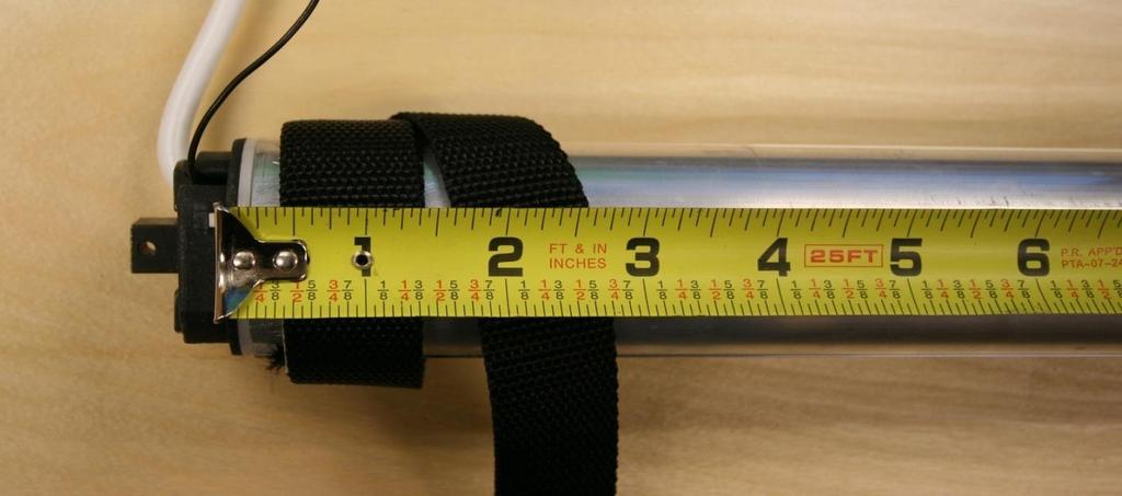
4 CONTACT PHONE Attach LH and RH Mounting Box to the cabinet sides using the #4x20mm Flat Head Screws. MAKE SURE THAT EACH SIDE IS PROPERLY ALIGNED WITH EACH OTHER. See Fig 1,2 and 3 and photo 1. The longer screws are to be used at the bottom of the mounting box. 2. Mount the telescoping clothes rail by attaching the side supports for the clothes rail using two M8x35mm Screws. Use the hex key to loosely tighten. 3. Adjust the telescoping rail to proper length and twist to lock it. After adjusted to desired width remove the side supports from step 2 and add the clothes pole. The main outer clothes pole must be cut to the correct length before it is added. It BUTTS up against the side supports and goes over the telescoping rail. Replace side supports and Re-tighten the M8 x35 Screws. 4. Lift the arms manually and ensure there is NO BINDING or scraping and that the arms move freely at all times. 5. Measure the closet opening (see Fig 1 )The metal motor tube needs to be cut 1 1/2 inches less than the closet opening(inside dimension). See photo 2 for where to hold the measuring tape. Do not include the motor head when measuring the tube. 6. Insert right side end cap into the metal tube and place white round plastic idler bearing onto right side end cap. Do not yet mount tube. 7. Mount right side strap with the strap clip and the small machine screw that is supplied. See photo 3. Drill through the tube with 3/32 bit and attach the strap with the screw so that the tape on the strap is directly across from the tape on the left side strap. This ensures that the straps are the same length when lifting the rotating arms. Do not try to drill through the lifting strap material as this is not necessary. The strap needs to be mounted about ¼ from the right end of the tube (see Photo 4) and the X on the tape needs to be against the motor tube so that the strap clip on the other end is positioned correctly. 4
5 8. Mount RIGHT side idler bracket for the motor tube using the 2 #10 screws supplied on right hand side at the top. Use the sticky foam to assist in placement of the bracket and to reduce vibration. See Fig 2 and photo 6 for where to position. The motor must be on the left side for lifting straps to be correct as they must lift from the top of the tube as opposed to the bottom of the tube 9 Mount LEFT side bracket with 2 # 10 screws provided, Use the sticky foam to assist in placement of the bracket and to reduce vibration.. See Fig 3 and photo 6 for where to position. 10. Place tube with motor into square opening in left bracket and then place right side tube into right side bracket (SEE photo 4 and 5) Make sure that straps are coming from the top of the tube as opposed to the bottom of the tube. Add the cotter pin to secure the motor in the left side bracket. 11. Ensure that motor tube is parallel with what will be the position of the clothes rod. Motor side of tube with cord must be on the left side 12. Manually unwrap the straps and attach to the predrilled mounting holes at the end of each rotating arm using the #6 machine screws and nuts. Do this while the arms are in the complete down position (Horizontal). Make sure that strap clips are secure and that straps are NOT twisted and that they line up with the arms. See Fig 4 for strap clip position. 13. If not being hardwired by an electrician, connect the plug to the motor cord. The brass screw goes with the black wire, the silver screw with the white wire and the green screw head goes with the green wire (ground). 14. Plug in the unit. The top button on the transmitter is for UP, the middle button is for STOP, and the bottom button is for DOWN. Ensure transmitter matches for the motor. 15. Ensure that the lifting straps and the rotating arms are in alignment when the rotating arms are operating. 5
6 CONTACT PHONE Set the limits Raise black cover to expose very small left and right keys. (see photo 7 and 8) 1. SET DOWN LIMIT. Press left key once then press DOWN button once... Now UP or DOWN buttons should respond momentarily. Use them to place rotating arm at its resting point with no slack in straps. Select the stop button (center button) once to complete the setting 2. SET UP LIMIT. Press left key once then press UP button once. Now UP or DOWN buttons should respond momentarily. Use them to locate the rotating arms just slightly forward (½ inch). Select the stop button (center button) once to complete the setting. Notes a) When entering in the limits settings you only have 5 seconds to BEGIN to command the motor after pressing the left key. b) In the process of adjustment, any coincidental press to the stop key will be considered as the limit setting is complete.to restart you must press the LEFT key again. C) LIMITS CAN BE RESET ANYTIME DURING THE LIFE OF THE PRODUCT. 17 Test the unit. If lifting straps have different levels of slack, the right or NON motor side strap can be adjusted by setting a new securing screw position. Ensure that at lower position the straps have no slack so that straps support the arms rather than just the housing support the arms. Only the right side or NON motor side strap can be adjusted at the motor tube. 6
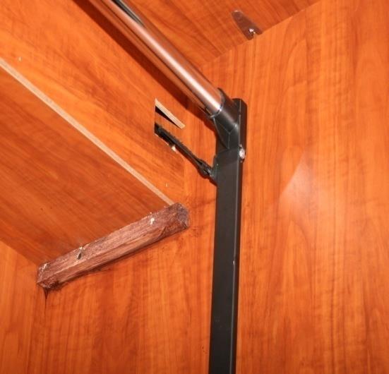
7 CONTACT PHONE Install the wireless wall switch with the hardware provided. If the Automated WardrobeLiftTM is installed inside a cabinet; please ensure the wireless, wall switch is mounted inside the cabinet. If wireless, wall switch is mounted out side the door, the switch may be activated inadvertently and could, potentially, cause damage to the cabinet door or the user when the door is opened to access the unit! 19 See photo 9 and 10 for an example of an enclosure that can used to conceal the motor tube. The motor tube can also be painted or covered with wood grain contact paper. 7

8 Trouble Shooting Reset button must use pin, small screw or paperclip to activate. Beeps are very quiet! PROBLEM Rotating arms are not stopping at proper points Lift does not respond or acts improperly. (Be sure to cut power and reconnect) Switch light out Lift does not go up straight Lift runs in reverse One switch operates two motors SOLUTION Reset the motor limits using the wireless switch. See motor limit step in the instructions. Press the reset button using a pin until 1 beep then immediately within 2 seconds press the up or down button on the switch. Unit should respond. If no response then proceed as follows. Press the reset button for approx. ten seconds using a pin. Hold until 2 beeps and release Wait another 10 seconds or more then re-associate the motor to a switch by pressing the reset button once for 1 beep then immediately within 2 seconds press the Up or Down button of the switch. Check battery Adjust the right side strap which is the non motor side strap. Remove the anchor screw and move the strap material accordingly and then reinsert the screw. See installation instructions. The left side (Motor Head)strap CANNOT be adjusted. Motor head needs to be on left side of tube when facing unit from the front. Lift the black cover on the switch and press the very small button on the right and hold for 3 seconds. Motor direction should now be changed Press the reset button (very small white button on the motor head) for ten seconds using a pin on the motor you want to disassociate. Hold until 3 beeps then release. Test all switches to make sure they will not operate the motor. Associate the motor to the correct switch by pressing the reset button once then immediately within 2 seconds pressing the Up or Down button of the correct switch. Make sure all other switches are not activated during this procedure. Set the motor limits. CONTACT PHONE
9 Fig. 1 Motor with Tube Clothes Pole Side Supports Rotating Arms Mounting Boxes WARNING Make sure the arms are mounted above the height of the user when in the down position Patent Pending9
10 Motor with Tube Fig. 2 Lifting Strap Distance from the back of the closet to the clothes rail should be at least 11 inches. Approx 1.5 to 3 in. Approx 4 to 8 in. The motor tube and clothes rail can be mounted as close to the ceiling as desired Approx 9 inches back front Right hand side view Patent Pending 10
11 Fig. 3 Lifting Strap Motor with Tube Approx 1.5 to 3 in. Motor Cord WARNING if motor is mounted too low it is possible to damage the unit when setting the the UP limit as too much leverage will be gained front Approx 4 to 8 in. back Motor mounted TOO low! Motor with Tube Wireless switch location Left hand side view Patent Pending 11
12 Fig. 4 Machine Screw # Long with hex nut Black Metal Clip Rotating Arm Patent Pending 12

13 Photo 1 Photo 2 13


14 Photo 4 Photo 3 Photo 5 Patent Pending 14

15 Photo 6 See approximate location of motor tube in relation to rotating arm Arm slightly forward when in up position Patent Pending 15


16 Photo 7 Photo 8 Photo 9 Photo 10 Patent Pending 16
Trackstar Motorized Folding Shade Installation Instructions
 Trackstar Motorized Folding Shade Installation Instructions Thank you for purchasing your new Trackstar folding shade. It has been custom-made from the highest quality materials to the dimensions you specified.
Top Down Rollstar Shade Installation Instructions
 Top Down Rollstar Shade Installation Instructions Thank you for purchasing your new Rollstar shade. It has been custom-made from the highest quality materials to the dimensions you specified. With proper
Rollstar Shade Installation Instructions
 Rollstar Shade Installation Instructions All Lifting Systems Inside or Outside Mount Thank you for purchasing your new Rollstar shade. It has been custom-made from the highest quality materials to the
Automatic Roof Hatch Opener
 Automatic Roof Hatch Opener Installation Guide REQUIRED TOOLS (These tools are required to complete the installation) Cordless Drill 1/8 1/4 Drill Bits 1/8 Pin Punch #2 Philips Bit Rachet Sharpie Hammer
ft. ft Signature Balsam Fir Tree ITEM Item 68607
 7.5 7.5 ft. ft Signature Balsam Fir Tree ITEM Item 68607 PARTS LIST A. BOTTOM B. MIDDLE C. TOP D. TREE STAND NUMBER OF PERSONS RECOMMENDED FOR ASSEMBLY: 2 SKU 68607 7.5 Signature Balsam Fir 2114 TIPS STANDARD
INSTALLING YOUR MOTORIZED ROLLER/SOLAR SHADE
 ROLLER/SOLAR SHADE PARTS INCLUDED: 4x Screws (per shade) 2x Mounting Brackets (per shade) 1x Plug-In Charger w/extension Cable* 1x Motor Cap Cover Remote Control(s) *Battery Motor Only TOOLS YOU WILL NEED:
Here we have the old lock on an exterior door (note more than one door was used for this article- taking the best pictures of the group)
") Alarm lock T2 Part 1 of 4 Installations Eugene Hansen 2004 This is the first part of four, 1st we will install a T2 Trilogy, 2 nd replacing the batteries, 3 rd replacing the solenoid and finally 4 th reprogramming
Alarm lock T2 Part 1 of 4 Installations Eugene Hansen 2004 This is the first part of four, 1st we will install a T2 Trilogy, 2 nd replacing the batteries, 3 rd replacing the solenoid and finally 4 th reprogramming
Installation Instructions Table of Contents
 Installation Instructions Table of Contents Pre- Installation of Garage Storage Lift 2 Layout the Garage Storage Lift 3 Installing the strut Channels 3 Install the Drive Assembly 5 Install the Drive Shaft
Fabric Studio Custom Roll Shades Installation Instructions
 Fabric Studio Custom Roll Shades Installation Instructions Cassette System Battery Motor Lifting System Inside or Outside Mount Thank you for purchasing your new roll shade. It has been custom-made from
CALIFORNIA TRIMMER MOWER MAINTENANCE MANUAL
 CALIFORNIA TRIMMER MOWER MAINTENANCE MANUAL 2 Table of Contents Section 1: General Information Page Handle Assembly Instructions 4 Maintenance All Models 6 Oil Change Procedures All Models 9 Height Adjustment
Single Panel Automatic Door
 Products That Move!!!TM Single Panel Automatic Door Flush Mount Tilt Back Installation Instructions 1 Installation 1. Add guides and motor tube to the final enclosure. See figure 1. 2. Place door into
IMPORTANT! Remote Control Instructions
 Remote Control Instructions FOR New Tarp Remote Control Installation Use these in place of the rocker switch and solenoid section of instructions in your roll tarp owner s manual. FOR Existing Electric
The M7 Direct Flow Intercooler (DFIC) Installation Guide
 Installation Guide") The M7 Direct Flow Intercooler (DFIC) Installation Guide This information is meant only as a guide. The author of this information,, or any M7 Tuning employees assumes no liabilities for any outcomes resulting
The M7 Direct Flow Intercooler (DFIC) Installation Guide This information is meant only as a guide. The author of this information,, or any M7 Tuning employees assumes no liabilities for any outcomes resulting
Wrestling Mat Lifters Installation Instructions
 Wrestling Mat Lifters Installation Instructions Suspending Stationary Mat Lifter to Steel Beams (1) Inspect the entire system for any freight damage. It is the installer s responsibility to ensure the
2005+ Roll Bar (Mm5RB-20.1 to -20.6) Recommended Center punch 1/8" pilot drill 1-3/4" Hole saw 2" Hole saw
 Recommended Center punch 1/8 pilot drill 1-3/4 Hole saw 2 Hole saw") 3430 Sacramento Dr., Unit D San Luis Obispo, CA 93401 Telephone: 805/544-8748 Fax: 805/544-8645 www.maximummotorsports.com 2005+ Roll Bar (Mm5RB-20.1 to -20.6) Recommended Center punch 1/8" pilot drill
3430 Sacramento Dr., Unit D San Luis Obispo, CA 93401 Telephone: 805/544-8748 Fax: 805/544-8645 www.maximummotorsports.com 2005+ Roll Bar (Mm5RB-20.1 to -20.6) Recommended Center punch 1/8" pilot drill
Roller Shades MOTORIZED SHADE. Simplicity. Installation & Care Instructions
 Roller Shades MOTORIZED SHADE Simplicity Installation & Care Instructions 152140 J 1/13/2016 GETTING STARTED A few simple tools are required: - Measuring tape - Power drill, drill bits - 1 4 Hex head and/or
60-72 Chevrolet C10 Power Rack & Pinion Kit Instructions # , , &
 60-72 Chevrolet C10 Power Rack & Pinion Kit Instructions # 8011740-01, 8011900-01, & 8011920-01 Unisteer offers a limited warranty against all manufacturer defects of their kits and supplied parts. Unisteer
2018 QOD TROUBLE SHOOTING MANUAL
 2018 QOD TROUBLE SHOOTING MANUAL TROUBLE-SHOOTING ISSUES WITH YOUR QOD 1. NO POWER OR INTERMITTENT POWER: STEPS TO ISOLATE PROBLEM AREA 1. Check USB Port: If you have lost power completely and are staring
GARAGE DOOR OPENER OWNER S MANUAL S3/S4
 GARAGE DOOR OPENER OWNER S MANUAL S3/S4 Features! Locking door during power failure: If power failure occurs while the door is operating, the door can be released by pulling the clutch down, allowing
1-3/8 Designer Metals Telescoping Traversing Rod Installation Instructions
 1-3/8 Designer Metals Telescoping Traversing Rod Installation Instructions Please read and follow all installation instructions provided for proper operation and enjoyment of your new drapery hardware
Training Documentation
 Training Documentation Manual Shades There are two styles of adjustment wheels for Manual Shades: External Adjuster No tools needed. Wheel is turned by hand. Slot Adjuster (Accessed thru bracket end) Flat
INSTRUCTION PLASTIC BATTERY BOX & CHARGER KIT
 LIFT CORPORATION Sht. 1 of 9 DSG# M-11-09 Rev. B Date: 08/12/13 INSTRUCTION PLASTIC BATTERY BOX & CHARGER KIT KIT P/N 285131-01 NOTE: Parts shown on sheets 1 and 2 are shipped as loose parts. Electrical
TOYOTA HIGHLANDER RUNNING BOARD HIGHLANDER HV Preparation
 Preparation Part Number: PT738-48080 Kit Contents Item # Quantity Reqd. Description 1 1 Driver Side Running Board 2 1 Passenger Side Running Board 3 4 /Middle Mount Bracket 4 2 Rear Mount Bracket 5 2 Rear
PRODUCT MANUAL Gecko Wireless One Zone LED Dimmer and Receiver
 Product Description The Gecko Wireless One Zone Wall LED Dimmer has been designed to bring light control easily. No wires or switch box locations are needed, just stick or mount the Gecko to any flat location
SEAT BELTS SECTION CONTENTS H RESTRAINTS SB-1
 H RESTRAINTS A SECTION SEAT BELTS B C D CONTENTS E PRECAUTIONS... 2 Precautions for Supplemental Restraint System (SRS) AIR BAG and SEAT BELT PRE-TEN- SIONER... 2 Precaution for Seat Belt Service... 2
Preparation Part Number: PT Kit Contents Item # Quantity Reqd. Description 1 1 Rear Spoiler 2 1 Hardware Kit. Hardware Bag Contents
 Preparation Part Number: PT478-11170-09 Kit Contents 1 1 Rear Spoiler 2 1 Hardware Kit Hardware Bag Contents 1 4 M5 Nut 2 4 Clip 3 4 Hole Plug Additional Items Required For Installation 1 1 Outer Drill
INSTALLATION / OPERATING INSTRUCTIONS Reese Elite Series FIFTH WHEEL SLIDER HITCH
 INSTALLATION / OPERATING INSTRUCTIONS Reese Elite Series FIFTH WHEEL SLIDER HITCH DEALER/INSTALLER: (1) Provide this Manual to end user. (2) Physically demonstrate hitching and unhitching procedures in
Electric Vehicle Charging Station
 EVoReel Electric Vehicle Charging Station INSTALLATION GUIDE AND USER MANUAL Model: Dual Output Pedestal Mount 30A EVoReel EVSE Model Numbers: With Basic EVSE: EV072-400-002A; With Intelligent ievse: EV072-410-002A;
Installation and Care Instructions
 WARDS WARDS REPLACE BATTERIES, REPLACE BATTERIES, WARDS WARDS REPLACE BATTERIES, REPLACE BATTERIES, THANK YOU for purchasing a Hunter Douglas Brilliance PowerRise shade. Your new shade has been custom
Installation Instructions Skylight FlexShades by Draper
 Caution 1 Read entire procedure before installing. Keep instructions for future reference. 2 Tools needed for installation: Cordless drill/screwdriver, with flathead, phillips, and 1 /4" nut driver attachments
Throttle Cable Pull - Patent Pending By: NetGain Controls, Inc.
 Throttle Cable Pull - Patent Pending By: NetGain Controls, Inc. Powering the future! Installation Guide 2011 All Rights Reserved NetGain Controls, Inc. 1 of 8 Introduction Thank you for purchasing a NetGain
Service Kit A
 Service Kit 753-05894A Date: Subject: Models Affected: June 28, 2010 Service Replacement for the 618-04360 and 618-04360A Tiller Transmissions N/A Read through and understand these instructions completely
SEAT BELT SECTION SB CONTENTS RESTRAINTS SB-1 PRECAUTION... 2 ON-VEHICLE REPAIR... 3
 RESTRAINTS SECTION SB A SEAT BELT B C D CONTENTS E PRECAUTION... 2 PRECAUTIONS... 2 Precaution for Supplemental Restraint System (SRS) "AIR BAG" and "SEAT BELT PRE-TEN- SIONER"...2 Precaution for Seat
TC1000 Service Manual SALES: CUSTOMER SERVICE:
 TC1000 Service Manual SALES: 800-278-3933 CUSTOMER SERVICE: 800-745-1373 Table of Contents Section Page I. Overview 2 II. Troubleshooting Tables 3 III. Maintenance Procedures Procedure 1 Removal and Reinstallation
EVO-1148AL/EVO-1149AL EVO Hood Breach
 EVO-1148AL/EVO-1149AL EVO Hood Breach Bill of Materials EVO-1148AL EVO Hood Breach Single Sprayer Part number Description Quantity EVO-12135AL EVO Hood Breach Single Sprayer 1 EVO-12136AL EVO Hood Breach
Installing the Wireless Charging upgrade kit in a 2018 XT5 (Platinum version)
") Installing the Wireless Charging upgrade kit in a 2018 XT5 (Platinum version) September 2, 2018 Tools needed: Wireless charger upgrade kit Plastic trim tools 7 mm nut driver Background: I purchased the
Installing the Wireless Charging upgrade kit in a 2018 XT5 (Platinum version) September 2, 2018 Tools needed: Wireless charger upgrade kit Plastic trim tools 7 mm nut driver Background: I purchased the
w w w. h d o n l i n e s h o p. d e DETACHABLE WINDSHIELD AND DOCKING HARDWARE KIT GENERAL INSTALLATION -J00325 REV Kit Number Models
 -J00 REV. 00-- DETACHABLE WINDSHIELD AND DOCKING HARDWARE KIT GENERAL Kit Number -A, 0-, -, 0-, -, - 0, -0 Models These kits fit and later FXST, FXSTB, FXSTC, and and later FXDWG Harley-Davidson model
Basic steps for installing the AmeriGlide Express Dumbwaiter
 Basic steps for installing the AmeriGlide Express Dumbwaiter 1. Remove Shroud. 2. Mount lower section of Track and Unit to hoistway wall and Brackets. 3. Remove Shipping Bracket from Top of Car. 4. Install
Installation Manual. stairlift. A 4724 Neukirchen/W, Salling 8 Tel: 07278/ , Fax: 07278/ Mobil: 0664/
 Installation Manual Ω MEGA stairlift A 4724 Neukirchen/W, Salling 8 Tel: 07278/3514-15, Fax: 07278/3514-12 Email: office.lehner@gmx.at Mobil: 0664/1612980 CONTENTS OBSERVE THE FOLLOWING POINTS BEFORE INSTALLATION!...
INSTRUCTION MANUAL 16K - Fifth Wheel Hitch
 You can take it with you. INSTRUCTION MANUAL 16K - Fifth Wheel Hitch Product No. 30047 DEALER/INSTALLER: END USER: (1) Provide this Manual to end user. (2) Physically demonstrate hitching and unhitching
Roller Shades MOTORIZED SHADE. Simplicity. Installation & Care Instructions
 Roller Shades MOTORIZED SHADE Simplicity Installation & Care Instructions 152140 I 8/12/2015 GETTING STARTED A few simple tools are required: - Measuring tape - Power drill, drill bits - 1 4 Hex head and/or
Product Packing List
 Product Packing List Product: SDHQ-55-1650-G3 Description: 2016+ Toyota Tacoma Hidden Winch Mount (1) Winch Mount SDHQ-55-1650-G3-A (2) Lower Support Brackets SDHQ-55-1650-G3-B (1) Lower Bumper Bracket
H15P. Toyota Hilux A-DECK Dual Cab
 Toyota Hilux A-DECK Dual Cab Page 1 of 14 Fitting Instructions Part Number H15 Toyota Hilux A-DECK Dual Cab 2015+ To suit Sports Bars Check contents of kit before commencing fitment and report any discrepancies
PRP Seats 570/800/900 RZR 4 Doors
 Install Instructions PRP Seats 570/800/900 RZR 4 Doors Remove all parts from the box and unwrap completely using the packaging to lay out the pieces. Tools Needed: (not included) 7/16 Open end wrench and
Vertical Vinyl Curtain Door
 Vertical Vinyl Curtain Door Face Mount Installation Instructions System Overview: Your Aleco Vinyl Vertical Curtain Door is a high quality, high performance flexible door system based on proven components
Technical Support (707)
") Installation Instructions UNIMATIC SHIFTER Fits: GM, Powerglide, Ford and Chrysler Transmissions See Application Guide for Specific Vehicles Catalog # 80775 WORK SAFELY! For maximum safety, perform this
Installation Instructions UNIMATIC SHIFTER Fits: GM, Powerglide, Ford and Chrysler Transmissions See Application Guide for Specific Vehicles Catalog # 80775 WORK SAFELY! For maximum safety, perform this
CHECKLIST & COMPONENTS
 Eclipse Compact www.rollershuttercompany.com Tel 0800 6444121 55mm Roller Garage Doors CHECKLIST & COMPONENTS EQUIPMENT REQUIRED 2 x Step ladders or hop ups Spirit level Tape measure Power drill 10mm A/F
BL400 Bed Lift. Warning! This bed lift is a very powerful tool and if used improperly could result in serious injury or death.
 BL400 Bed Lift Warning! This bed lift is a very powerful tool and if used improperly could result in serious injury or death. Be aware that this bed will raise and also lower with crushing force, and has
Mobile Video Installation Guide
 000MVGUIDE Revision 04/29/04 Mobile Video Installation Guide This installation guide offers examples of mobile video system types and suggested layouts. The installation of your system will depend upon
INSTALLATION AND OPERATING INSTRUCTIONS
 ASTRO ENVELOPE FEEDER AMC-2000 INSTALLATION AND OPERATING INSTRUCTIONS INTRODUCTION Thank you for purchasing the Astro Envelope Feeder. It is fast, efficient, reliable, and designed to provide many years
PRODUCT MANUAL Gecko Wireless 2 Zone LED Dimmer and Receiver
 Product Description The Gecko Wireless 2 Zone Wall LED Dimmer has been designed to bring light control easily. No wires or switch box locations are needed, just stick or mount the Gecko to any flat location
Model 2300DL Installation Guide
 Model 2300DL Installation Guide POWER ACCESS CORPORATION 4 HERSHEY DRIVE, DOCK 4 ANSONIA, CT 06401 800-344-0088 WEBSITE: www.power-access.com EMAIL: salesinfo@power-access.com 1 STANDARD PARTS MODEL 2300DL
IMPORTANT! DO NOT THROW AWAY THE SHIPPING CARTON AND PACKING MATERIAL
 Operator s Manual IMPORTANT! DO NOT THROW AWAY THE SHIPPING CARTON AND PACKING MATERIAL ii Table of Contents Operator Safety... 1 Introduction... 2 Unpacking and Setup... 3 Unpacking... 3 Setup... 4 ROCKET
READ AND FOLLOW ALL SAFETY INSTRUCTIONS SAVE THESE INSTRUCTIONS
 7.5 Swift Lock Ready Shape Tree (Patent Pending) Instructions IMPORTANT SAFETY INSTRUCTIONS When using electrical products, basic precautions should always be followed including the following: READ AND
Installation Guide Section1
 Certification Test Report 908.42 MHz Low Power Communication Device Transceiver 372 MHz Discrete Receiver FCC ID: KJ8-0001715 IC: 3540A-0001715 FCC Rule Part: 15.249 IC Radio Standards Specification: RSS-210
Z-Gate Universal Shifter
 Installation Instructions Z-Gate Universal Shifter Fits: GM, Ford, Lincoln and Chrysler Transmissions See Application Guide for Specific Applications Part #80681 Rev 06/01/2018 WORK SAFELY! For maximum
BENCH GRINDER MODEL CBG6RZ OPERATING & MAINTENANCE INSTRUCTIONS
 BENCH GRINDER MODEL CBG6RZ OPERATING & MAINTENANCE INSTRUCTIONS 0100 9 Thank you for purchasing this CLARKE BENCH GRINDER. Before attempting to operate this machine, please read this instruction manual
INSTALLATION AND OPERATING INSTRUCTIONS
 ASTRO ENVELOPE FEEDER AMC-2000 INSTALLATION AND OPERATING INSTRUCTIONS INTRODUCTION Thank you for purchasing the Astro Envelope Feeder. It is fast, efficient, reliable, and is designed to give you many
INSTALLATION INSTRUCTIONS
 INSTALLATION INSTRUCTIONS Honda Dealer: Please give a copy of these instructions to your customer. PARTS LIST (15) (8) (12) (14) (13) (10) (11) (18) (17) (1) Accessory Application Publications No. TRX500FA/FGA
vertical cradle lifts installation instructions
 vertical cradle lifts installation instructions models 7,000 lb. thru 45,000 lb. important: read this manual before beginning installation of cradle lift. 5560 Ulmerton Road Clearwater, Florida 33760 1.800.878.5560
Dual Roller Fascia Coupled FlexShades Assembly and Installation Instructions
 Dual Roller Fascia Coupled FlexShades Assembly and Installation Instructions 1 Upon receiving your Coupled FlexShades, open and inspect to make sure you have received the proper sizes, fabrics, and mounting
MPX Light harness installation instructions
 Light harness installation 800081-MPX 800081-MPX Light harness installation instructions (module installed under the vehicle hood) See page #5 for UI technical bulletin #124g for Intermittent Cluster,
Cellular Shades MOTORIZED SHADE Top Down - Bottom Up. Installation & Care Instructions
 Cellular Shades MOTORIZED SHADE Top Down - Bottom Up ucontact@udoblinds.com 1-855-205-8442 Installation & Care Instructions 152746A 7/2/2018 GETTING STARTED A few simple tools are required: - Measuring
HELIOMOTION QUICK ASSEMBLY GUIDE PV-650
 HELIOMOTION QUICK ASSEMBLY GUIDE PV-650 PART I - FOUNDATION M16 M16 8x 2 PLACEMENT 1m Area around flange must be clear of obstacles in a 1 meter radius. Place the unit in a location that receives sunlight
Technical Installation and Service Manual RollSeal 1733 County Road 68 Bremen, Alabama 35033
 Technical Installation and Service Manual RollSeal 1733 County Road 68 Bremen, Alabama 35033 4801-5159 rev. 05/14 Technical Installation and Service Manual Page 1 of 26 1. Ratings and Specifications Motor
Prusa i3 Printer Assembly Guide
 Prusa i3 Printer Assembly Guide Special thanks to Carlos Sanchez and Miguel Sanchez for the graphics. All graphics captured from their great animation: http://www.carlos-sanchez.com/ Prusa3/ For copyright
Cable Shift Linkage Kit
 Cable Shift Linkage Kit INSTALLATION INSTRUCTIONS ididit column to GM Trans FOR PART NUMBER S: 2801000010, 2802000010 ididit Column to 350 Trans...Pg 1-4 ididit Column to 400 Trans...Pg 5-8 ididit Column
P-600. Technical Manual. Troubleshooting Repairs Replacements
 P-600 Technical Manual Troubleshooting Repairs Replacements Table of Contents P-600 Lift Symptoms and Problems Finding the Problem Before Getting Inside 3 Pneumatic Systems 4 Electrical Systems 5 Mechanical
PORSCHE 928. PKT Installation 1.6. No air pump version. Air pump version
 PORSCHE 928 PKT Installation No air pump version Air pump version 1.6 Tools Torque wrench 10mm socket 12mm socket 13mm socket 5mm allen socket 6mm allen socket 8mm allen key Caliper Supplies Blue Loctite
PARTS LIST: 8581 DODGE LONG ARM BRACKETS 03-13
 SYNERGY MFG. 870 INDUSTRIAL WAY, SAN LUIS OBISPO, CA (805) 242-0397 8580 03-12 DODGE 2500/3500 4X4, 06-08 1500 MEGACAB 4X4 LONG ARM SUSPENSION KIT V3.0 GENERAL NOTES: These instructions are also available
SAM Series 2-Wire and 3-Wire Clock
 Installation Manual V9.0 SAM Series -Wire and 3-Wire Clock Current as of November 06 The Sapling Company, Inc. SAM Series -Wire and 3-Wire Clocks Table of Contents Table of Contents Important Safety Instructions
R Y T E C. Turbo-Seal Insulated Gen 2
 R Y T E C Turbo-Seal Insulated Gen 2 Installation Manual P.O. Box 403, One Cedar Parkway, Jackson, WI 53037 Phone: 262-677-9046 Fax: 262-677-2058 Rytec Website: www.rytecdoors.com, Rytec On-line store:
TOYOTA FJ CRUISER AIR DAM/LIGHT BAR Preparation
 Preparation Part Number: PT278-35071 Kit Contents Item # Quantity Reqd. Description 1 1 Air Dam / Light Bar Hardware Bag 1 Contents Item # Quantity Reqd. Description 1 2 Screw, M6x33mm, Wafer Head 2 2
LEXUS CT 200h ILLUMINATED DOOR SILLS Preparation
 Preparation Part Number: PT922-89100 Kit Contents Item # Quantity Req'd. Description 1 1 Door Sill, Front Right Hand 2 1 Door Sill, Front Left Hand 3 1 Door Sill, Rear Right Hand 4 1 Door Sill, Rear Left
L-SERIES CLUTCHES L-SERIES CLUTCHES. Getting Started INSTALLATION INSTRUCTIONS INSTALLATION INSTRUCTIONS
 L-SERIES CLUTCHES INSTALLATION INSTRUCTIONS Thank you for purchasing your new L-Series Clutches. They have been custom-made from the highest quality materials. to the dimensions you specified. With the
Photo 1. Shift pattern gate plate
 Installation Instructions MAGNUM GRIP STREET BANDIT SHIFTER Fits: GM, Chrysler, and Ford Automatic Transmissions See Application Guide for Specific Vehicles Catalog # 81050 WORK SAFELY! For maximum safety,
SEAT BELTS SECTION CONTENTS H RESTRAINTS SB-1
 H RESTRAINTS A SECTION SEAT BELTS B C D CONTENTS E PRECAUTIONS... 2 Precautions for Supplemental Restraint System (SRS) AIR BAG and SEAT BELT PRE-TEN- SIONER... 2 Precaution for Seat Belt Service... 2
Thunder Power Tarp Kit Operation. Dual Arm Curb Side Stowing Single Arm Curb Side Stowing Flex Arm Curb Side Stowing.
 Thunder Power Tarp Kit Operation Dual Arm Curb Side Stowing Single Arm Curb Side Stowing Flex Arm Curb Side Stowing 011-52475 Rev - 2 P a g e USE THE PROCEDURES BELOW TO OPERATE THE TARP SYSTEM Powering
At-FST Series I N S TA L L AT I O N A N D O P E R AT I N G I N S T R U C T I O N S W W W. A I G I S M E C H. C O M
 FULL HEIGHT GALVANIZED STEEL TURNSTILE SINGLE UNIT 3 60 At-FST Series AT-FST SERIES I N S TA L L AT I O N A N D O P E R AT I N G I N S T R U C T I O N S W W W. A I G I S M E C H. C O M SAFETY PRECAUTIONS
RTS518 - Rhino Heavy Duty 2 & 3 Crossbar System Hyundai iload, imax, i800, H-1.
 RTS518 - Rhino Heavy Duty 2 & 3 Crossbar System Hyundai iload, imax, i800, H-1. NOTE: Please read these instructions carefully prior to installation. Check the contents of kit before commencing fi tment
Adult Car Plans. A comprehensive guide to help you build an official Soap Box Derby Adult Car
 Adult Car Plans A comprehensive guide to help you build an official Soap Box Derby Adult Car 1 Table Of Contents Introduction...Page 3 Adult Car Floorboard...Page 4 Step One Steering Stop Installation...Page
MC2500. Installation and Operation Manual
 MC2500 Installation and Operation Manual Important: This manual contains specific cautionary statements relative to worker safety. Read this manual thoroughly and follow as directed. It is impossible to
R Y T E C. Installation Manual. Models. L (9-½ Side Column) S (14 Side Column)
 S (14 Side Column)") R Y T E C Spiral LH Installation Manual Models L (9-½ Side Column) S (14 Side Column) P.O. Box 403, One Cedar Parkway, Jackson, WI 53037 Phone 262-677-9046 Fax 262-677-2058 Rytec website: www.rytecdoors.com
R Y T E C Spiral LH Installation Manual Models L (9-½ Side Column) S (14 Side Column) P.O. Box 403, One Cedar Parkway, Jackson, WI 53037 Phone 262-677-9046 Fax 262-677-2058 Rytec website: www.rytecdoors.com
TCI FastGate Shifter Installation Instructions
 151 INDUSTRIAL DRIVE ASHLAND, MISSISSIPPI 38603 http://www.tciauto.com TELEPHONE: 662-224-8972 FAX LINE: 662-224-8255 E-MAIL: tech@tciauto.com TCI 616541 FastGate Shifter Installation Instructions The
MF 9690, 9790, Challenger 660, 670
 Ag Leader Technology Parts List Note: Indented items indicate parts included in an assembly listed above Quantity by Model Part Name/Description Part No. MF 9690 MF 9790 Challenger 660 Challenger 670 Instruction
The Chameleon Trac II Patent Pending M-Series User s Manual
 The Chameleon Trac II Patent Pending M-Series User s Manual YOU MAY ALSO VIEW OUR GENERAL OPERATION VIDEO ONLINE AT: www.marionbrush.com Please read entire manual prior to using this system. Page 1 The
Hiniker Company th St. P.O. BOX 3407 Mankato, MN VEHICLE INSTALLATION INSTRUCTIONS FORD 4x4: SUPER DUTY F
 Page of VEHICLE INSTALLATION INSTRUCTIONS FORD x: 00-007 SUPER DUTY F0 30 0 0 INSTRUCTION SHEET NO: 037 Rev. A IMPORTANT: Read The Snowplow Operators Manual Before Assembling This Kit. MFR. Snowplow Prep
INSTALLATION INSTRUCTIONS
 INSTALLATION INSTRUCTIONS Accessory HARD FRONT DOORS P/N 0SU95-HL4-104 Application SXS1000M3/M3P/M3L/M5D/ M5P/M5L Honda Dealer: Please give a copy of these instructions to your customer. Publication No.
MEDIA LED. Pendant Standard Mount Installation ou de montage WARNING:
 MEDIA LED Pendant Standard Mount WARNING: Disconnect main power at the source prior to installation! Thread gripper base onto 1 /4 20 stud, or with #8 screw. Depress gripper nozzle to insert aircraft cable.
AIR FILTER MODEL NO: AF1000 OPERATION & MAINTENANCE INSTRUCTIONS PART NO:
 AIR FILTER MODEL NO: AF1000 PART NO: 6471160 OPERATION & MAINTENANCE INSTRUCTIONS 1208 INTRODUCTION Thank you for purchasing this Clarke Air Filter. Before you try to use this product, read this manual
Chain/Belt Drive Models PRE-INSTALLATION CONSIDERATIONS
 38968503545. 08/2017 ASSEMBLY/INSTALLATION Chain/Belt Drive Models PRE-INSTALLATION CONSIDERATIONS This opener includes parts and supplies needed for installation in most garages and on most garage doors.
Remote Control Electric Curtain Track User Manual
 User Manual A. Over View Thank you for purchasing the Remote Electric Curtain Track from Y2SHOP. The curtain tracks are widely used in window treatments, home theatres, projector screen covers, room dividers,
Assembly instruction. Pendant Light Toccata GENERAL REMARKS ON SAFETY: Technical data: BOM
 GENERAL REMARKS ON SAFETY: Read all of these instructions before installing fixtures. Keep all of the instructions for future reference. Turn off power before installing fixture. Installation is to be
Portable Lighting Equipment Operating Instructions Table of Contents
 Portable Lighting Equipment Operating Instructions Table of Generac Magnum Ingersoll Rand TEREX AMIDA TEREX GENIE Model: MLT3060 Model: LIGHTSOURCE Model: Amida AL4000 series Model: TML4000N Generac Magnum
Installation Guide Rollerdor RD55 Econ Roller Garage Door
 Installation Guide Rollerdor RD55 Econ Roller Garage Door 1 Finished door Rollerdor RD55 Econ Roller Garage Door CHECKLIST & COMPONENTS EQUIPMENT REQUIRED 2 x Step ladders or hop ups Spirit level Tape
Installation Guide Rollerdor RD77 Econ Roller Garage Door
 Installation Guide Rollerdor RD77 Econ Roller Garage Door 1 Finished door Rollerdor RD77 Econ Roller Garage Door CHECKLIST & COMPONENTS EQUIPMENT REQUIRED 2 x Step ladders or hop ups Spirit level Tape
Installation Manual for the Following Modular Blast Chiller Kits GBF ESK GBC440ESK GBF ESK GBC837 GBF ESK GBC1200ESK 1
 Installation Manual for the Following Modular Blast Chiller Kits GBF440-385ESK GBC440ESK GBF837-727ESK GBC837 GBF1200-1065ESK GBC1200ESK 1 Depending on the model kit you are installing, there will be one
Subject: Models/Years Affected: Origination Date: Revision Date:
 Subject: Models/Years Affected: Origination Date: Revision Date: Intermittent Cluster, Radio and HVAC Display Resets on Snow Plow Trucks 2014 Chevrolet Silverado 1500 2015 and beyond Chevrolet Silverado
R3 Roller Garage Door Opener
 R3 Roller Garage Door Opener INSTALLATION INSTRUCTIONS OWNERS COPY 1 WARNING: It is vital for the safety of persons to follow all instructions. Failure to comply with the installation instructions and
Instruction Manual MB4 Rolling garage door opener
 Instruction Manual MB4 Rolling garage door opener INSTALLATION INSTRUCTIONS OWNERS COPY 1 WARNING: It is vital for the safety of persons to follow all instructions. Failure to comply with the installation