Radiator Kit /1500ROZD Standby Generator Sets
|
|
|
- Katherine Andrews
- 5 years ago
- Views:
Transcription


1 TT 816 INSTRUCTIONS 8/91 Radiator Kit /1500ROZD Standby Generator Sets This instruction is intended to finalize assembly of the radiator kit to the generator set. The unit was fully assembled prior to testing and then partially disassembled for shipping. The partial disassembly may vary from the instruction given due to manufacturing procedures. The illustration and parts listing in the this instruction shows all components of the radiator kit. The written procedure deals only with the components which require final assembly. See Figure 1. WARNING Accidental starting can cause death or serious personal injury. Turn Generator Master Switch to OFF position, disconnect power to battery charger, and remove battery cables (remove negative lead first and reconnect it last) to disable generator set before working on any equipment connected to generator. The generator set can be started by automatic transfer switch or remote start/stop switch unless these precautions are followed. INSTALLATION 1. Install four radiator supports to skid using 32 screws X , split lock washers X 24 1, and nuts X Install idler bushing and idler pulley Lubricate fan shaft and idler shaft bearings, see Lubrication Procedure for further information. 3. Mount two radiator support brackets to radiator supports using 16 screws X split lock washers X 24 6, and nuts X NOTE Radiator must be supported during the entire time for Steps 4, 5, and 6. Position radiator assembly A on skid and secure with two radiator brackets using two screws X , two split lock washers X 26 10, and four nuts X Do not final tighten hardware at this time. 5. Install radiator assembly to radiator support bracket using eight screws X , plain washers X 25 29, split lock washers X 26 10, and nuts X Use shims (7 gauge, in.) and (16 gauge, 0.06 in.), as necessary, to mount radiator so that fan pulley and engine pulley are vertically aligned. See Figure 1 for fan pulley alignment procedure. 6. Adjust radiator brackets so that radiator is in vertical alignment. Final tighten hardware as referenced in Step 4.
2 STEP 9.1 STEP 9.2 STEP 12.1 STEP 8 STEP 4.1 STEP 13 STEP 4.2 STEP 6 STEP 10 STEP 11 Figure 1a. Installation of Radiator Assembly
3 STEP 12.2 STEP 16.1 STEP 15 STEP 18.4 STEP 14.2 STEP 16.2 STEP 18.3 STEP 18.2 STEP 18.1 STEP 14.1 STEP 17 STEP 2 STEP 7 STEP 1 STEP 3 STEP 5 Figure 1b. Installation of Radiator Assembly
4 7. Attach one end of lower radiator hose X to radiator outlet and the other end to radiator outlet pipe using two hose clamps Attach one end of radiator hose X to radiator outlet pipe and the other end to engine inlet tube using two hose clamps Install two radiator hoses X on each end of one radiator (inlet) pipe using two hose clamps X Connect this assembly to radiator inlet and engine using two hose clamps X Repeat procedure for second radiator pipe. 9. Connect upper radiator hose brace and upper radiator support brace to radiator using two screws X , plain washers X 25 1, and lock nuts X Attach two hose clamps to secure upper radiator pipes to upper radiator braces. 10. Install radiator hose X on each end of (intercooler supply) pipe and attach to lower radiator and engine using four hose clamps Install radiator hose X on each end of (intercooler return) pipe and attach to lower radiator and engine using four hose clamps Attach vent lines to upper radiator inlet tubes using eight cable ties X Secure right side tube with conduit clip X Reconnect wiring harness connector to radiator level switch at top of radiator. Secure wiring harness with cable tie X Install poly V belt See Figure 1 for belt installation instructions. 15. Install two mounting brackets to engine using four screws X and lock nuts X Use bracket as a template and drill four 0.28 in. (7 mm) dia. holes. 16. Install right side belt guard using four screws X , split lock washers X 20 1, and plain washers X Install lower left side belt guard using screw X , lock washer X 22 1, and nut X Install upper left side belt guard , front belt guard , and top belt guard using 34 screws X , split lock washers X 20 1, and plain washers X Close all coolant drain petcocks and fill with coolant. Reference appropriate literature (specification sheet) for capacity. 20. Consult Installation Guide and Prestart Checklist or additional information regarding generator set installation and initial startup. 4
5 Parts Listing (* Radiator Kit Components Requiring Installation) Qty. Description Part No. * 1 Radiator assembly A * 4 Nut, 1/4 20 lock X * 2 Nut, 3/8 16 lock X Screw, 5/16 18 x 1 1/4 X * 16 Screw, 1/2 13 x 1 1/2 X * 38 Washer, 1/4 split lock X Washer, 1/4 split lock X Bushing, 3/8 F NPT x X /2 M NPT reducer 1 Nipple, pipe 1 1/2 NPT x 4 in. X Washer, 5/16 split lock X 21 1 * 1 Washer, 3/8 split lock X Washer, 3/8 split lock X Elbow, 1 1/2 NPT F 45 deg. X * 32 Washer, 5/8 split lock X Washer, 5/8 split lock X 24 1 * 16 Washer, 1/2 split lock X 24 6 * 2 Washer, 7/16 x 1 x 5/64 plain X 25 1 * 8 Washer, 13/16 x 1 15/16 x X /16 plain * 38 Washer, 9/32 x 5/8 x 1/16 plain X Valve, drain 3/8 NPT X * 10 Washer, 3/4 split lock X * 8 Clamp, 3 3/4 hose X Screw, 1/4 20 x 1 X Screw, 1/4 20 x 1 1/2 X * 38 Screw, 1/4 20 x 3/4 X Screw, 1/4 20 x 1 X * 4 Screw, 1/4 20 x 1 1/2 X * 1 Tie, 4 in. cable X * 8 Tie, 21 in. cable X Washer,.68 ID beveled X Washer,.44 ID beveled X * 1 Hose, 4 1/2 ID x 5 radiator X * 4 Hose, 3 1/2 ID x 5 radiator X * 1 Hose, 4 1/2 ID x 10 radiator X * 4 Hose, 2 I.D. x 8 in. X * 32 Screw, 5/8 11 x 1 3/4 X Screw, 5/8 11 x 2 1/4 X Screw, 3/8 16 x 1 1/4 X * 1 Screw, 3/8 16 x 3/4 X * 2 Screw, 3/8 16 x 1 X * 10 Screw, 3/4 10 x 2 X Clamp,.44 ID insulated X Clamp, 2 1/8 ID insulated X Qty. Description Part No. 1 Plug, pipe 3/4 NPT X Plug, 1/4 NPT F recess. hex. pipe X * 1 Clip, conduit X Nut, 1/4 20 X 81 1 * 1 Nut, 3/8 16 X 83 2 * 32 Nut, 5/8 11 X Nut, 5/8 11 X 85 3 * 12 Nut, 3/4 10 X * 16 Nut, 1/2 13 X 89 8 * 8 Clamp, 2 1/2 in. hose Switch assembly, level Tube, inlet Gasket, inlet * 4 Clamp, 4 7/8 in. hose * 2 Support, radiator support * 4 Support, radiator * 1 Pipe, intercooler return * 1 Pipe, intercooler supply * 2 Pipe, radiator inlet 90 deg * 1 Bushing, idler * 1 Pulley, idler Bushing, pulley Pulley * 1 Pipe, radiator outlet * 1 Guard, belt (top) * 1 Guard, belt (upper left side) * 1 Guard, belt (lower left side) * 1 Guard, belt (right side) * 2 Bracket, mounting * 1 Belt, poly V * 1 Guard, belt Support, radiator (upper right side) Support, radiator (upper left side) * 2 Bracket, radiator Support, radiator (lower right side) Support, radiator (lower left side) * 12 Shim, 7 ga. (.179) * 12 Shim, 16 ga. (.0598) Bracket, mounting Gasket, pressure sensor Cover, pressure sensor * 1 Brace, upper radiator hose * 1 Brace, upper radiator support * 2 Clamp, hose
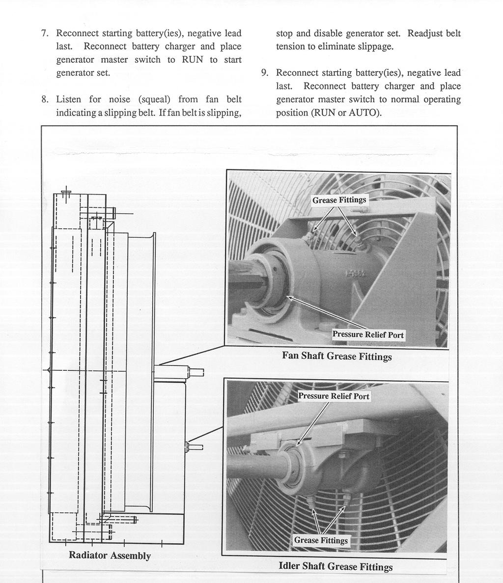
6 SCHEDULED MAINTENANCE Refer to the generator operation manual and engine operation manual for specific periodic service regarding the generator set. The fan shaft and idler shaft bearing on this radiator kit must be lubricated regularly to avoid bearing damage. Lubrication of the bearings is required every 200 hours of operation when the generator set is run in ambient temperatures less than 85 F (29 C). Lubricate the bearings every 100 hours of operation if the generator is operated at ambient temperatures greater than 85 F (29 C), or if the generator set is run in dusty, humid environment. Lubricate the bearings at the specified interval according to the following procedure. NOTE It may be convenient to remember to lubricate the radiator fan shaft and idler shaft bearings whenever the engine lube oil is changed. WARNING Accidental starting can cause death or serious personal injury. Turn Generator Master Switch to OFF position, disconnect power to battery charger, and remove battery cables (remove negative lead first and reconnect it last) to disable generator set before working on any equipment connected to generator. The generator set can be started by automatic transfer switch or remote start/stop switch unless these precautions are followed. WARNING Exposed moving parts can cause severe injury. Keep hands, feet, hair, and clothing away from belts and pulleys when unit is running. Replace guards, covers, and screens before operating generator set. Lubrication Procedure The fan shaft and idler shaft bearings should be lubricated with a lithium complex base, multi purpose grease with anti rust, anti foam, extreme pressure additives and a minimum dropping point of 400 F (204 C). Mobil Mobilith AW2 NLGI, Grade 2 is one lubricant suitable for this application. 1. Place generator master switch to OFF position. Disconnect starting battery(ies), negative lead first and disconnect power to battery charger. 2. Remove belt guards to expose fan shaft and idler shaft bearings. 3. Using a grease gun filled with specified grease, inject grease into the two bearings on the fan shaft block and the two bearings on the idler shaft block. See Figure 2. Inject grease until a 1/8 1/4 in. (3 6 mm) grease column shows at the bearing pressure relief port. NOTE The fan shaft and idler shaft bearings are equipped with pressure relief ports to prevent bearing damage if the bearings are over lubricated. 4. Use a rag to wipe off excess grease from bearing pressure relief ports. 5. Inspect fan drive belt for damage or wear, replace if necessary. Check fan belt tension using a poly V belt tension gauge and adjust if necessary. Proper tension for a new belt is 500 lbs. (227 kg) and for a used belt is lbs. ( kg). 6. Reinstall belt guards using original hardware. 6
7
Radiator Kit kw Standby Generator Set
 Radiator Kit 299878 1200 kw Standby Generator Set These instructions are intended to finalize assembly of the radiator kit to the generator set. The generator set was fully assembled prior to testing and
TT /13b INSTALLATION INSTRUCTIONS. Introduction
 TT-5 /b INSTALLATION INSTRUCTIONS Original Issue Date: 5/09 Model: 0RESA, 0REYG, 0RES, 0RYG, and RGEN0 Market: Residential/Commercial Subject: Oil Makeup Kits GM654 -KP, GM654-KP, and GM8987-S Introduction
INSTALLATION INSTRUCTIONS
 TT-1079 9/95 INSTALLATION INSTRUCTIONS Original Issue Date: 9/95 Model: 20-60 kw (Detroit Diesel Powered) Market: Industrial Subject: Sound Shield Enclosure Kits PA-324742-SD, 324742-SD, PA-324743-SD,
Remote Mount Voltage Regulator Kits PA and PA SD For kw Standby Generator Sets
 TT-08 /94 INSTALLATION INSTRUCTIONS Remote Mount Voltage Regulator Kits PA-76 and PA-76-SD For 0-00 kw Standby Generator Sets The remote mount voltage regulator kit is recommended whenever the voltage
Ford 6.0L. Part #: Part #: BD GASKET PART# will be needed for this installation.
 1 BD EGR COOLER 2003-2007 Ford 6.0L Part #: 1090201 Part #: 1090202 PLEASE READ ALL INSTRUCTIONS BEFORE INSTALLATION BD GASKET PART# 1090002 will be needed for this installation. 2 K I T C O N T E N T
SOUND GUARD SST-E INSTALLATION INSTRUCTIONS & PARTS LIST
 SOUND GUARD SST-E INSTALLATION INSTRUCTIONS & PARTS LIST FOR DIESEL GENERATOR MODELS 12.5-15.0 ETD SOUND GUARD SST-E INSTALLATION INSTRUCTIONS & PARTS LIST FOR DIESEL GENERATOR MODELS 12.5-15.0 ETD INTRODUCTION
INSTALLATION INSTRUCTIONS
 TT-07 9/0 INSTALLATION INSTRUCTIONS Original Issue Date: 9/0 Model: 7/RY, 0/RY/RZ, 0/CCE/CCZ, and 8/0/.E Generator Sets Market: Residential/Commercial and Marine Subject: Ignition Module Service Kit GM789
Procharger Stage II Intercooled Supercharger System (11-14 GT)
") Procharger Stage II Intercooled Supercharger System (11-14 GT) Installation Time: Approximately one day. Installed on 2012 Mustang GT 5.0/Manual Required Tools 3/8 Socket Set (Standard and Metric) 1/2
Procharger Stage II Intercooled Supercharger System (11-14 GT) Installation Time: Approximately one day. Installed on 2012 Mustang GT 5.0/Manual Required Tools 3/8 Socket Set (Standard and Metric) 1/2
Service Parts 20ROZJB REOZJB. Industrial Generator Sets. Models:
 Service Parts Industrial Generator Sets Models: 20ROZJB 20-230REOZJB See Group 701: Literature, inside this manual for part numbers of engine and accessory parts catalogs See TP-6009 Parts Catalog Industrial
DewEze Clutch Pump Kit Ford 6.2L Gas, A Pump, Side Port, 2011+
 DewEze Clutch Pump Kit 700512 Ford 6.2L Gas, A Pump, Side Port, 2011+ INSTALLATION INSTRUCTIONS 1. The installation of this kit requires trained decisionmaking concerning clearances, tying components together,
DewEze Clutch Pump Kit Ford 6.2L Gas, A Pump, Side Port, INSTALLATION INSTRUCTIONS 1. The installation of this kit requires trained decis
 DewEze Clutch Pump Kit 700564 Ford 6.2L Gas, A Pump, Side Port, 2014+ INSTALLATION INSTRUCTIONS 1. The installation of this kit requires trained decisionmaking concerning clearances, tying components together,
6. Remove OEM bolts from engine at locations A, B, and C. Lay the wiring off to the side.
 700359 DewEze Clutch Pump Kit #700359 Ford 5.4L, 6.8L w/ and w/o A/C AA mount 1999- INSTALLATION INSTRUCTIONS 1. Disconnect the battery. 2. Drain the radiator. 3. Remove the air cleaner assembly. 4. Remove
FMK265SD F L DIESEL WITH DUAL ALTERNATORS
 WITH DUAL ALTERNATORS This kit will NOT work on trucks equipped with adaptive steering. INSTALLATION NOTES 1. Disconnect negative batteries cables. Remove the air duct from the passenger side and the black
AET48 Owner s Manual. TOW AERATOR Owner s Manual AET48 Beginning Serial #: Replacement Parts
 Tine Row Kit Complete tine row set for replacement of one complete row of tines. Includes mounting plates, spacer, and all hardware. TOW AERATOR Owner s Manual AET48 Beginning Serial #: 0206001 Tine Kit
RZT TWIN STICK HYDRO DRIVE 250 Z 44" & 50" SERIES 0
 Parts Manual for RZT TWIN STICK HYDRO DRIVE 250 Z 44" & 50" SERIES 0 MODEL ERZT185440BVE RZT22500BVE2 McDonough, GA, 30253 U.S.A. COPYRIGHT 2006 SNAPPER PRODUCTS, INC. ALL RIGHTS RESERVED. Revision 1,
3.4L V6 SUPERCHARGER 7 TH INJECTOR KIT
 Part Number: 00602-17620-260 00602-17620-261 00602-17620-263 00602-17620-264 00602-17620-274 00602-17620-275 00602-17620-276 Section I Installation Preparation Kit Contents Item # Quantity Reqd. Description
JODALE PERRY. Parts List & Mounting Instructions. Jacobsen HR9016 JDP BUILT FOR LIFE
 JODALE PERRY Parts List & Mounting Instructions Jacobsen HR9016 JDP BUILT FOR LIFE Jacobsen HR9016 Mounting Instructions Standard Parts 1 - LH Rear Mounting Bracket 1 - RH Rear Mounting Bracket 1 - Front
NISSAN TITAN 3 BODY LIFT INSTALLATION INSTRUCTIONS KIT # 40053
 3651 N Highway 89 Chino Valley, AZ 86323 (928) 636-7080 NISSAN TITAN 3 BODY LIFT INSTALLATION INSTRUCTIONS 2004-2009 KIT # 40053 Installation of a Performance Automotive Group body lift kit will change
DODGE DAKOTA 3 KIT INSTALLATION INSTRUCTIONS KIT# 60043
 DODGE DAKOTA 3 KIT INSTALLATION INSTRUCTIONS 2000-2002 KIT# 60043 Installation of a Performance Automotive Group body lift kit will change the vehicle s center of gravity and handling characteristics both
2016+ NISSAN TITAN XD
 PARTS LIST AND PARTS INCLUDED 1PC MISHIMOTO INTERCOOLER 2PC SILICONE BOOTS WITH DURACORE TECHNOLOGY 4PC CONSTANT-TENSION T-BOLT CLAMPS 2PC ALUMINUM SPACERS MOUNTING HARDWARE CAUTION Never work on the cooling
General Information. Assembly Instructions for A. Base Update 2005 Kit. Update Instructions Yield-Pro 1625 Planter
 Update Instructions 2004 Yield-Pro 1625 Planter Used with: General Information 2004 Yield-Pro 1625 Planter! When you see this symbol, the subsequent instructions and warnings are serious - follow without
LChevrolet Camaro Supercharger Kit
 PART #92000A Important Notes: 2010-2013 6.2LChevrolet Camaro Supercharger Kit The use of fuel additives (ie. octane boosters) is not recommended. There is a possibility that these chemicals can damage
Assembly Instructions for A, A, A, & A
 Update Instructions Yield-Pro 1225/1625 Planter Used with: Yield-Pro 1225 Planter Yield-Pro 1625 Planter General Information! When you see this symbol, the subsequent instructions and warnings are serious
INSTALLATION INSTRUCTIONS
 TT-338 /0 INSTALLATION INSTRUCTIONS Original Issue Date: /0 Model: Transfer Switches with Programmable Controllers Market: ATS Subject: Transformer Kits GM6369 (480 V) and GM6859 (600 V) Introduction A
Not for Reproduction. BILLY GOAT AERATOR Owner's Manual AE401, AE401H, AE401H5T Replacement Parts. AE Owner s Manual TINE ROW KIT TINE KIT P/N
 BILLY GOAT AERATOR Owner's Manual AE401, AE401H, AE401H5T Replacement Parts TINE ROW KIT Complete tine row set for replacement of one complete row of tines. Includes mounting plates, spacer, and all hardware.
EXPANSION TANK PARTS LIST AND INSTALLATION GUIDE
 PARTS LIST AND INSTALLATION GUIDE PARTS LIST 2 PC APPLICATION-SPECIFIC MOUNTING BRACKETS 2 PC BLACK, ANODIZED 6061 ALUMINUM CATCH CANS 4 PC SILICONE HOSES 4 PC PLASTIC BARBED FITTINGS 4 PC WORM-GEAR CLAMPS
Illustrated Parts List for VMAC System V Ford F Super Duty 6.0L Power Stroke Diesel Without Dual Alternators
 Illustrated Parts List for VMAC System V900080 2007 2003.25 Ford F250-550 Super Duty 6.0L Power Stroke Diesel Without Dual Alternators 1 - Kit Pack List... 3 2 - Fastener Pack, 3800456... 5 3 - Compressor
DURAMAX LML EGR DELETE
 2011-2012 DURAMAX LML EGR DELETE Sinister Diesel EGR Delete Kit A B C D E F G H PACKING LIST: QTY. A B C D E F G H QTY. 1 4 1 1 1 3 1 4 Description Blue Coolant Hose M8 x 25 Hex Head Bolts Exhaust Block
LARGE FRAME REAR TINE TILLERS SERIES 2
 Parts Manual for LARGE FRAME REAR TINE TILLERS SERIES 2 MODEL R5002B R5002R R8002B R8002BE RT5 RT5X RT8 RT8S McDonough, GA, 30253 U.S.A. COPYRIGHT 2006 SNAPPER PRODUCTS, INC. ALL RIGHTS RESERVED. Revision
Installation Manual v1.0: Twin CP3 Fuel Injection Kit Dodge 5.9L
 Installation Manual v1.0: Twin CP3 Fuel Injection Kit 2004.5-2007 Dodge 5.9L Figure 1 - Full Kit Photo 25 Figure 2 - Hardware Kit Please read all instructions before installation. This kit is not emissions
Service Parts. Doosan 11.1 L. Engine. Engine Model: Generator Models: 180/200REZX 180/200RZX TP /09
 Service Parts Engine Engine Model: Doosan. L Generator Models: 80/00REZX 80/00RZX TP-0 /09 Table of Contents Introduction... Numbering System Significance... Illustrations... How to Find Part Numbers...
Scion FR-S ZN6. GTX2867R Gen2 (Internal Wastegate) Installation Instructions GPP P/N #
 Installation Instructions GPP P/N #") TURBO KIT Scion FR-S ZN6 Subaru BRZ ZC6 GTX2867R Gen2 (Internal Wastegate) Installation Instructions GPP P/N # 11518000 Vehicle Type Chassis Code Engine Code Transmission Model Year Scion FR-S DBA-ZN6
TURBO KIT Scion FR-S ZN6 Subaru BRZ ZC6 GTX2867R Gen2 (Internal Wastegate) Installation Instructions GPP P/N # 11518000 Vehicle Type Chassis Code Engine Code Transmission Model Year Scion FR-S DBA-ZN6
2017+ L5P Duramax 3 ½ Down Pipe & EGR Fix Kit
 2017+ L5P Duramax 3 ½ Down Pipe & EGR Fix Kit Covers installation of PN s: WCF100630, WCF100829 Note: This Kit is for off road competition use only! Off Road Competition Use Tuning & Exhaust System is
2000 DODGE DURANGO INSTALLATION INSTRUCTIONS KIT #60053
 WARNING This body lift kit should only be installed on vehicles in good working condition. Before installation, the vehicle should be thoroughly inspected for evidence of corrosion or deformation of the
Special Note About The JDM High Performance Water Pump:
 Page 1 of 30 JDM Engineering, Inc. home Call Us! 732-780- 0770 back to Installation Instructions Electric Fan Upgrade Kit Electric Fan Wiring Diagram Thank you for your purchase of the JDM Engineering
INSTALLATION INSTRUCTIONS 97 FORD EXPEDITION
 INSTALLATION INSTRUCTIONS 97 FORD EXPEDITION 1. Read the instructions completely and carefully before you begin. Check the kit for proper contents (refer to the part s list and the picture diagrams). Before
Max IV Rear Axle Replacement For models after Serial Number and all rear splined axle replacements.
 Max IV Rear Axle Replacement For models after Serial Number 19089 and all rear splined axle replacements. 10/8/03 Max IV Snap Ring Rear Axle replacement.doc Tools required: 9/16 Wrench 6 Extension Steel
Ford 6.0L Regulated Return Kit
 2003-2007 Ford 6.0L Regulated Return Kit A. Passenger Rear Return B. Line (Longer w/ 1-90 fitting) C. Driver Rear Return Line (Shorter w/ 1-90 fitting) D. Fuel Return Line (2 female fittings) E. Passenger
INSTALLATION INSTRUCTIONS 2000 NISSAN FRONTIER CREW CAB 2WD/4WD - KIT #40003
 This body lift kit should only be installed on vehicles in good working condition. Before installation, the vehicle should be thoroughly inspected for evidence of corrosion or deformation of the sheet
FIELD & BRUSH MOWER SERIES 0
 Parts Manual for SERIES 0 MODEL FB13250BS (7085922) GM2513BS (3070980) GM2513H (3070101) GM2513H (7085924) GM2515KAW (3070103) GM2515KAW (7085923) GM2516BVG (3800017) COPYRIGHT 2009 GIANT-VAC ALL RIGHTS
Instruction Sheet IS Date: 8/6/2013
 Instruction Sheet Date: 8/6/2013 Bulletin #: Subject: 072709/072710/072711/072811, Belt Keeper Update Kit Purpose: To instruct Lastec personnel Model Numbers: 3300, 3600, 3380, 3680, 4520 Serial Numbers:
Service Parts. John Deere 3029DF 3029TF 3029TF270. Engine. Engine Models: Generator Models: 20ROZJB REOZJB 20DSJB DSEJB.
 Service Parts Engine Engine Models: John Deere 3029DF 3029TF 3029TF270 Generator Models: 20ROZJB 20--40REOZJB 20DSJB 20--40DSEJB TP- 12/03b Table of Contents Description Page Description Page Introduction...
MODEL NO & UP MODEL NO & UP MODEL NO & UP MODEL NO & UP
 MODEL NO. -900 & UP MODEL NO. 00-900 & UP MODEL NO. 0-900 & UP MODEL NO. 0-900 & UP SKID SPRAYER FORM NO. 99-055 REV. B SET-UP AND PARTS LIST Refer to the illustrated Parts List for the details of parts
FIELD & BRUSH MOWER SERIES 0
 Parts Manual for SERIES 0 MODEL FB13250BS FB13250BV FB15250KW McDonough, GA, 30253 U.S.A. COPYRIGHT 2005 SNAPPER PRODUCTS, INC. ALL RIGHTS RESERVED. Revision 1, 8/30/2005 Table Of Contents PAGE GROUP
Service Parts 28/32EOZD 23/27EFOZD 25/28EFOZD. Marine Generator Sets. Models: TP /09b
 Service Parts Marine Generator Sets Models: 28/32EOZD 23/27EFOZD 25/28EFOZD TP-6273 2/09b Description Page Introduction... 3 Numbering System Significance... 3 Illustrations... 3 How to Find Part Numbers...
PACER 30 VACUUM IMPORTANT SAFETY INSTRUCTIONS READ AND UNDERSTAND ALL INSTRUCTIONS BEFORE OPERATING OR SERVICING MACHINE
 DANGER! PACER 30 VACUUM IMPORTANT SAFETY INSTRUCTIONS READ AND UNDERSTAND ALL INSTRUCTIONS BEFORE OPERATING OR SERVICING MACHINE Failure to Observe These Instructions Can Cause Fire, Electrical Burn, Shock
2001 CHEVY SILVERADO HD INSTALLATION INSTRUCTIONS - KIT #183
 WARNING This body lift kit should only be installed on vehicles in good working condition. Before installation, the vehicle should be thoroughly inspected for evidence of corrosion or deformation of the
TOYOTA TUNDRA 3 BODY LIFT INSTALLATION INSTRUCTIONS 2014 KIT# 5643
 3651 N Highway 89 Chino Valley, AZ 86323 (928) 636-7080 www.p-a-g.net TOYOTA TUNDRA 3 BODY LIFT INSTALLATION INSTRUCTIONS 2014 KIT# 5643 Installation of a Performance Automotive Group body lift kit will
Parts Manual. Generator Set. DFHA (Spec A G) DFHB (Spec A G) DFHC (Spec A F) DFHD (Spec A D) with PowerCommand 3100 Controller
 DFHB (Spec A G) DFHC (Spec A F) DFHD (Spec A D) with PowerCommand 3100 Controller") Parts Manual Generator Set with PowerCommand 3100 Controller DFHA (Spec A G) DFHB (Spec A G) DFHC (Spec A F) DFHD (Spec A D) English Original Instructions 9-2014 960 0241 (Issue 10) To avoid errors or
Parts Manual Generator Set with PowerCommand 3100 Controller DFHA (Spec A G) DFHB (Spec A G) DFHC (Spec A F) DFHD (Spec A D) English Original Instructions 9-2014 960 0241 (Issue 10) To avoid errors or
Installation Instructions
 2011-2013 LML DURAMAX COMPOUND-ADD 2011-2015 LML A Duramax TURBO KIT Add INSTALL A Turbo INSTRUCTIONS Compound Kit Installation Instructions 1-800-955-0476 - www.industrialinjection.com - info@industrialinjection.com
»Product» Safety Warning
 #C1354 Installation Instructions 1999-2002 Chevy/GM 1500 4wd 3.5" Combo Lift Kit Read and understand all instructions and warnings prior to installation of product and operation of vehicle. Zone Offroad
STX-38 EFI Stump Grinder with Intelli-Sweep
 Form No. 3421-244 Rev A STX-38 EFI Stump Grinder with Intelli-Sweep Model No. 23214 Serial No. 402000000 and Up Register at www.toro.com. Original Instructions (EN) *3421-244* A Ordering Replacement Parts
Installation and Commissioning of Auxiliary Power Unit
 Models PC6012 PC6013 PC6014 PC6015 PC6022 PC6023 PC6024 Installation and Commissioning of Auxiliary Power Unit 30-871-21 Rev. E Warning & Cautions Vehicles with longer wheel bases should have the APU mounted
Genset. Parts Catalog HDKAG
 Genset Parts Catalog HDKAG To avoid errors or delay in filling your parts order, always give the MODEL, SPEC NO. and SERIAL NO. from the Onan nameplate. For handy reference, insert your nameplate information
This information covers procedures for replacing the sealant for the crankshaft cover on the Volvo D16F engine.
 Volvo Trucks North America Greensboro, NC USA DService Bulletin Trucks Date Group No. Page 1.2008 216 50 1(17) Sealant Crankshaft Cover, Replacement D16F Sealant Crankshaft Cover, Replacement W2005773
Powerstroke EGR Delete A B C
 20-203 6.7 Powerstroke EGR Delete A B C D E F G H I J K Part # A B C D E F G H I J K PACKING LIST: QTY. 3 5 2 Description Sensor Bracket Exhaust Blockoff Plate Straights Barbed Brass Fitting 39 5/8 Coolant
* PLEASE READ INSTRUCTIONS PRIOR TO INSTALLATION
 XDP 6.0L Complete EGR Delete Kit w/up-pipe Item Number: XD169 PACKING LIST: 2 - Lined 3/4" Hose Clamps, 1-180 Coolant Tube, 1-3/4 Silicone Hose, 1 - Stainless Steel Up-pipe 1 - EGR Valve Block-Off Plate,
Hydro Cut Series Walk-Behind Mowers
 Parts Manual HP Product Mfg. No. Description 92 Hydro Cut, HP Kawasaki, 2 inch (CE) Hydro Cut Series Walk-Behind Mowers Rev. 0/200 Table Of Contents PRODUCT COMPONENTS PAGES Engine Deck & Handle Bars
»Product» Safety Warning
 #J9320, J9321 Installation Instructions 1986-1995 Jeep YJ 3" Body Lift Kit Read and understand all instructions and warnings prior to installation of product and operation of vehicle. Zone Offroad Products
B-026INT October 6, 1999 FUEL FILTER BRACKET RETROFIT (JAPAN ONLY) GENERAL RETURN THIS TO: INITIAL HERE TECHNICIAN NO.
 GENERAL RETURN THIS TO: INITIAL HERE TECHNICIAN NO.") 5 SERVICE BULLETIN B-026INT October 6, 1999 FUEL FILTER BRACKET RETROFIT (JAPAN ONLY) GENERAL It has come to the attention of Buell Distribution Corporation that a certain number of 2000 Model X1 and S3/T
5 SERVICE BULLETIN B-026INT October 6, 1999 FUEL FILTER BRACKET RETROFIT (JAPAN ONLY) GENERAL It has come to the attention of Buell Distribution Corporation that a certain number of 2000 Model X1 and S3/T
I. Before starting installation
 5. Park the vehicle on a clean, dry, flat, level surface and block the tires so the vehicle cannot roll in either direction. A. Disconnect battery cables 1. Disconnect the negative cable first, then the
INSTALLATION INSTRUCTIONS
 INSTALLATION INSTRUCTIONS HDX LED GRILLE APPLICATION: 013-017 Dodge Ram 1500 PART NUMBER: 34-1035 ITEM QUANTITY DESCRIPTION TOOLS NEEDED 1 1 HDX LED GRILLE 10MM SOCKET,3 UPPER BRACKET A, DRIVER () AND
BEFORE BEGINNING INSTALLATION
 COMPLETE CHASSIS FUEL LINE KITS For 1996-2000 Honda Civic Equipped with B-Series Engine INSTALLATION INSTRUCTIONS PLEASE study these instructions carefully before beginning this installation. Most installations
Installation Manual v1.0: Twin CP3 Fuel Injection Kit Dodge 6.7L
 04/05/2012 Dodge 2010-2011 6.7L Twin CP3 701-900-2356-INST Installation Manual v1.0: Twin CP3 Fuel Injection Kit 2010-2011 Dodge 6.7L Figure 1 - Full Kit Photo 29 Figure 2 - Hardware Kit (800) 949-60002
LML 3 Y-Bridge Kit or High Flow Intake Bundle Package
 2011-2016 LML 3 Y-Bridge Kit or High Flow Intake Bundle Package Covers installation of PN s: WCF100607, WCF100691, WCF100716, & WCF100353 Note: This Kit is for off road competition use only! Overview-
OPERATOR S MANUAL FABRIC 3-BAG GRASS CATCHER PART NO PRINTED 8/2012 PRINTED IN USA
 OPERATOR S MANUAL FABRIC -BAG GRASS CATCHER Models: GC-STC-V This manual contains the operating instructions and safety information for your Scag mower accessory. Reading this manual can provide you with
C11 D5 and D6 GENSET (PCC0300) CONTENTS
 CONTENTS") CONTENTS 0100-3984 Engine Accessories (Denso Rad)... 5 0100-4024 Engine Accessories (SRF Rad)... 7 0179-3766 Battery Charger Instl... 9 0179-3771 Miniature Circuit Breaker Instl... 11 0179-3772 Circuit
CONTENTS 0100-3984 Engine Accessories (Denso Rad)... 5 0100-4024 Engine Accessories (SRF Rad)... 7 0179-3766 Battery Charger Instl... 9 0179-3771 Miniature Circuit Breaker Instl... 11 0179-3772 Circuit
Ford E350, E450 Van LITER DIESEL ENGINE W/SINGLE OE ALTERNATOR TYPE B Uses TM-16, 4-3/4 Poly Groove Rear Port Compressor PARTS LIST
 2006-04 Ford E350, E450 Van 1784 6.0 LITER DIESEL ENGINE W/SINGLE OE ALTERNATOR TYPE B Uses TM-16, 4-3/4 Poly Groove Rear Port Compressor PARTS LIST 1 6m-1.0 x 15 Bolt 1 6m-1.0 x 45 Bolt 3 6m Flat Washer
Equipped with AEM Dryflow Filter No Oil Required! INSTALLATION INSTRUCTIONS PART NUMBER C (Gun Metal Grey Finish) 2015 Ford Mustang 2.
 2015 Ford Mustang 2.") Equipped with AEM Dryflow Filter No Oil Required! INSTALLATION INSTRUCTIONS PART NUMBER 26-3001C (Gun Metal Grey Finish) 2015 Ford Mustang 2.3 Turbo ITEM NO. PART NUMBER DESCRIPTION QTY. 1 2-1523C TUBE;
Equipped with AEM Dryflow Filter No Oil Required! INSTALLATION INSTRUCTIONS PART NUMBER 26-3001C (Gun Metal Grey Finish) 2015 Ford Mustang 2.3 Turbo ITEM NO. PART NUMBER DESCRIPTION QTY. 1 2-1523C TUBE;
SLP Camaro ZL1 STAGE 3 (650 HP)
") SLP - 2012 Camaro ZL1 STAGE 3 (650 HP) PART #26002 PACKING LIST Before installation, use this check list to make sure all necessary parts have been included. ITEM QTY CHECK PART NUMBER DESCRIPTION 1. 1
SLP - 2012 Camaro ZL1 STAGE 3 (650 HP) PART #26002 PACKING LIST Before installation, use this check list to make sure all necessary parts have been included. ITEM QTY CHECK PART NUMBER DESCRIPTION 1. 1
Timing Belt: Service and Repair Installation NOTE: Check the water pump for water leakage and the oil seal for oil leakage.
 1991 Daihatsu Truck Rocky L4-1589cc 1.6L SOHC Page 1 Timing Belt: Service and Repair Installation NOTE: Check the water pump for water leakage and the oil seal for oil leakage. Repair any water leakage
Installation Manual v2.2: Twin CP3 Fuel Injection Kit Dodge 5.9L
 12/13/11 ATS Twin CP3 Kit 701-900-2272-INST Installation Manual v2.2: Twin CP3 Fuel Injection Kit 2003-2004 Dodge 5.9L Figure 1 - Full Kit Photo 26 Figure 2 - Hardware Kit 1 Please read all instructions
Worldlawn Power Equipment, Inc. Industrial Park 2415 Ashland Ave. Beatrice, NE Toll Free Number:
 Parts Catalog R WYRZ46S/50U/60U Residential Zero Turn Mower Worldlawn Power Equipment, Inc. Industrial Park 2415 Ashland Ave. Beatrice, NE 68310 Toll Free Number: 1-800-267-4255 Table of Contents Table
lu. ücr ii- w - ~ ~. It It ~ o B Belt Drive Hydraulics FORD ~ èf ~ o (/ (/ ~ -c w $: $: cr oi- -czcr ~ g ~ cr
 lu. SYSTEM FORD va 7.3L Diesel 1994 1/2-97 Direct Injection w-w/o AC 7542B Belt Drive Hydraulics l- ~ èf ~ ~ o 0 ~ ~. o Q.'( l. ~d It It ~ s: cr oi- -czcr w ~. -c.. (/ o -c w cr ii-!j ücr "- cr ~ o cr
62 Deck Idler Kit High Speed
 Part No. 00 FORM NO. -899 6 Deck Idler Kit High Speed For Model 70 Serial No. 99000 to 99000 For Model 7 Serial No. 9900 to 99000 INSTALLATION INSTRUCTIONS Loose Parts Note: Use the chart below to identify
LAWN TRACTORS ELECTRIC CLUTCH HYDRO DRIVE SERIES "G"
 Parts Manual for LAWN TRACTORS ELECTRIC CLUTCH HYDRO DRIVE SERIES "G" MODEL LT160H42GBV LT160H42GBV2 LT180H48GBV2 WLT160H42GBV WLT180H48GBV2 McDonough, GA, 30253 U.S.A. COPYRIGHT 2006 SNAPPER PRODUCTS,
Parts Manual. RV Generator Set. HDCAA (Spec A D) HDCAB (Spec A D) English Original Instructions (Issue 9)
 HDCAB (Spec A D) English Original Instructions (Issue 9)") Parts Manual RV Generator Set HDCAA (Spec A D) HDCAB (Spec A D) English Original Instructions 0-0 9 09 (Issue 9) Introduction This parts catalog applies to the standard generator sets listed below. Parts
Parts Manual RV Generator Set HDCAA (Spec A D) HDCAB (Spec A D) English Original Instructions 0-0 9 09 (Issue 9) Introduction This parts catalog applies to the standard generator sets listed below. Parts
INSTALLATION INSTRUCTIONS DODGE DAKOTA 2 KIT # 682 (2WD), 692 (4WD) 3 KIT # 683 (2WD), 693 (4WD)
, 692 (4WD) 3 KIT # 683 (2WD), 693 (4WD)") INSTALLATION INSTRUCTIONS 1997-1999 DODGE DAKOTA 2 KIT # 682 (2WD), 692 (4WD) 3 KIT # 683 (2WD), 693 (4WD) Installation of a Performance Accessories body lift kit will change the vehicle s center of gravity
INSTALLATION INSTRUCTIONS 1997-1999 DODGE DAKOTA 2 KIT # 682 (2WD), 692 (4WD) 3 KIT # 683 (2WD), 693 (4WD) Installation of a Performance Accessories body lift kit will change the vehicle s center of gravity
Installation Instructions for: TOYOTA 4.5L SUPERCHARGER SYSTEM
 Installation Instructions for: TOYOTA 4.5L SUPERCHARGER SYSTEM 1995-1997 Land Cruiser * PREMIUM FUEL REQUIRED * Magnuson Products LLC 1990 Knoll Drive, Bldg A, Ventura, CA 93003 (805) 642-8833 phone *
INSTALLATION INSTRUCTIONS FOR COZY CAB A-1 AIR CONDITIONING KIT
 INSTALLATION INSTRUCTIONS FOR COZY CAB A-1 AIR CONDITIONING KIT 05-11 INSTALLATION INSTRUCTIONS A-12235 Air Conditioner Kit Cab set up instructions; This air conditioning kit is designed to be used with
SS41HF Mitsubishi Pajero NS & NT V8/V9 Series 3.2 Litre Turbo Diesel (4M41 Engine) 3.8 Litre V6 Petrol (6G76 Engine)
 3.8 Litre V6 Petrol (6G76 Engine)") SS41HF Mitsubishi Pajero NS & NT V8/V9 Series 3.2 Litre Turbo Diesel (4M41 Engine) 3.8 Litre V6 Petrol (6G76 Engine) 21/7/2010 Parts List ITEM PART NO DESCRIPTION QTY 1 570-133-200 BODY - SNORKEL (SS41HF)
SS41HF Mitsubishi Pajero NS & NT V8/V9 Series 3.2 Litre Turbo Diesel (4M41 Engine) 3.8 Litre V6 Petrol (6G76 Engine) 21/7/2010 Parts List ITEM PART NO DESCRIPTION QTY 1 570-133-200 BODY - SNORKEL (SS41HF)
SIDE RECOVERY SYSTEM (WRECKER) PARTS MANUAL
 PARTS MANUAL") SIDE RECOVERY SYSTEM (WRECKER) PARTS MANUAL 1080 Hykes Road Greencastle, PA 17225 Phone (717) 597-7111 www.jerr-dan.com 5-376-000115 Rev 0 - May 01, 2008 2008 Jerr-Dan Corporation. All Rights Reserved.
SIDE RECOVERY SYSTEM (WRECKER) PARTS MANUAL 1080 Hykes Road Greencastle, PA 17225 Phone (717) 597-7111 www.jerr-dan.com 5-376-000115 Rev 0 - May 01, 2008 2008 Jerr-Dan Corporation. All Rights Reserved.
Section 10 Exploded Views and Parts Lists
 Sheet Metal Drawing No. 0D3150-A 40 Generac Power Systems, Inc. Sheet Metal Drawing No. 0D3150-A 1 --------- 1 SEE ENGINE EXPLODED VIEW of ENGINE 2 099258 1 KEY-WOODRUFF 6 x 22MM 3 067198N 1 BEVELLED WASHER
CAFS Air Compressor Service Parts List Models 100-D, 120-D, 150-D, 200-D
 Document Number Issue Date 3/18/15 Rev. Date 1/24/18 CAFS Air Compressor Service Parts List Models 100-D, 120-D, 150-D, 200-D Pump Models HL200K, HL300K, HL400K Index: See Pages Component Model 100-D,
SUPERCHARGER. ON-VEHICLE INSPECTION 1. INSPECT SUPERCHARGER OIL LEVEL HINT: With the engine cold, check the oil level on the dipstick.
 EG45 ONVEHICLE INSPECTION 1. INSPECT OIL LEVEL HINT: With the engine cold, check the oil level on the dipstick. (a) Park the vehicle on a level spot and turn the engine off. (b) 4WD: Remove the LH front
INSTALLATION INSTRUCTIONS
 TT-5 7/6i INSTALLATION INSTRUCTIONS Original Issue Date: /08 Model: 6-60 kw Residential and Light Commercial Generator Sets Market: Residential/Commercial Subject: Maintenance Service Kits GM65, GM66,
C15 D5 and D6 (PCC1300 and 1301) CONTENTS
 CONTENTS") CONTENTS 0100-3920 Engine Accessories (Denso... 5 Radiator) 0100-4025 Engine Accessories (SRF Radiator)... 7 0179-3766 Battery Charger Instl... 9 0179-3771 Miniature Circuit Breaker Instl... 11 0179-3772
CONTENTS 0100-3920 Engine Accessories (Denso... 5 Radiator) 0100-4025 Engine Accessories (SRF Radiator)... 7 0179-3766 Battery Charger Instl... 9 0179-3771 Miniature Circuit Breaker Instl... 11 0179-3772
Retriever 5100G/P. 11/89 revised 10/02 FORM NO
 Retriever 5100G/P PARTS LIST Advance MODELS 56497000, 56497010 This parts list is for machines after serial number 353005 All models covered in this manual are OBSOLETE 11/89 revised 10/02 FORM NO. 56042216
Quiet Collector. Model No & Up
 FORM NO. -8GB Rev A Quiet Collector Model No. 795-890000 & Up Operator s Manual IMPORTANT: Read this manual, and your tractor manual, carefully. They contain information about your safety and the safety
Parts Manual PZ Please read the operator manual carefully and make sure you understand the instructions before using the machine.
 Parts Manual PZ 60 967 045601-00 Please read the operator manual carefully and make sure you understand the instructions before using the machine. When you need spare parts or support in service questions,
RigMaster Power Service and Repair Manual Document # S400909
 Document # S400909 S4.0 Enclosure Parts Breakdown for 2005 and newer To perform many of the repair procedures in this manual it may be necessary to remove a portion of the enclosure to gain access to components.
Disassembly and Assembly
 SENR9973-01 September 2007 Disassembly and Assembly 400C Industrial Engine HB (Engine) HD (Engine) HH (Engine) HL (Engine) HM (Engine) HN (Engine) HP (Engine) HR (Engine) Important Safety Information Most
Collector Drive for 60 Mower
 FORM NO. -66 Collector Drive for 60 Mower Model No. 7965-990000 & Up Operator s Manual IMPORTANT: Read this manual, and your tractor manual, carefully. They contain information about your safety and the
XDP Complete EGR Race Track Kit w/up-pipe. Item Number: XD144
 XDP Complete EGR Race Track Kit w/up-pipe Item Number: XD144 PACKING LIST: 2 - Lined 3/4" SS Hose Clamp 1-3/4 Silicone Hose 1 - XDP Engraved EGR Valve Block-Off Plate with O-ring 1 - EGR Cooler Block-Off
Appendix 3 Exploded Views and Parts Lists
 Engine, Alternator Drive and Starter Assembly Drawing No. 0D5057-A 40 Generac Power Systems, Inc. Engine, Alternator Drive and Starter Assembly Drawing No. 0D5057-A 1 0C5598 1 BEARING CARRIER, FRONT 2
1. GENERAL INFORMATION WARRANTY- PARTS - SERVICE SERIAL # ITEM # Printed in Canada Issue Date: October 2010 Revision 12
 TABLE OF CONTENTS SECTION PAGE 1 GENERAL INFORMATION 2 2 SAFETY GUIDELINES 3 3 OPERATION 4 3.1 How the Compressor Works 4 3.1.1 Components 4 3.1.2 Controls 5 3.1.3 Inlet Air System 6 3.1.4 Discharge System
NISSAN FRONTIER 2 & 4WD AUTOMATIC & MANUAL TRANS. KING & CREW CAB MODELS 3 BODY LIFT KIT INSTALLATION INSTRUCTIONS KIT# 40083
 3651 N Highway 89 Chino Valley, AZ 86323 (928) 636-7080 www.p-a-g.net NISSAN FRONTIER 2 & 4WD AUTOMATIC & MANUAL TRANS. KING & CREW CAB MODELS 3 BODY LIFT KIT INSTALLATION INSTRUCTIONS 2005-2011 KIT# 40083
FRONT TINE TILLERS SERIES 0 & 1
 Parts Manual for FRONT TINE TILLERS SERIES 0 & 1 MODEL 300T 301T 401TCR 500T 500TC 500TRC 501T 501TC McDonough, GA, 30253 U.S.A. COPYRIGHT 2006 SNAPPER PRODUCTS, INC. ALL RIGHTS RESERVED. Revision 6, 3/7/2006
ALL PRODUCT INDEX RCK60B-22BX
 ALL PRODUCT INDEX RCK60B-22BX UNIVERSAL JOINT GEAR BOX/PULLEY/BLADE MOWER DECK/WHEEL LINKAGE/LIFT ARM ACCESSORIES Ref. RCK60B-22BX Page 65160 Item Part No. Description Book UNIVERSAL JOINT 01A001 UNIVERSAL
MODEL NO & UP MODEL NO & UP MODEL NO & UP MODEL NO & UP MODEL NO.
 9-0688 MODEL NO. 00-800 & UP MODEL NO. 0-800 & UP MODEL NO. 5-800 & UP MODEL NO. -800 & UP MODEL NO. 0-800 & UP SKID SPRAYER with the Centrifugal Pump FORM NO. 95-9095 SET-UP AND PARTS CATALOG SAFETY AND